1
Integrity Instruments
232M100 Series User Manual
Digital I/O Characteristics
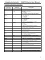
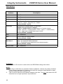
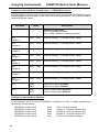
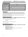
The following chart lists the Digital I/O characteristics and values.
Characteristic
Digital I/O Current
Value
I/O line source & sink 25 ma
Total current PORT2 200 ma
Digital I/O Voltage Levels
Input Off (0) = 0V - 0.8V
Input On (1) = 2.0V - 5.0V
Output Off (0) = 0.6V max.
Output On (1) = 4.3V min.
Pulse Counter Input
1 Mhz max. input rate
32 bit counter capture
Counter increments on high-low transition
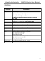
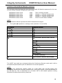
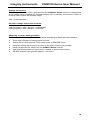
Digital Port Configuration Example
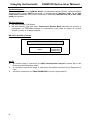
Any Digital I/O configuration changes made to the I/O Module using the ‘T’ command
are stored in EEPROM location 0x03.
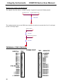
EEPROM Location 0x03
Port 2 I/O Configuration
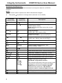
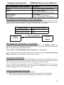
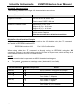
When using either the ‘T’ command or directly writing to EEPROM using the ‘W’
command, a binary 1 at a bit location puts the I/O line into Input mode, while a binary 0 at
a bit location puts the I/O line into Output mode.
NOTE
All numeric data is represent as ASCII Hexadecimal integers
•
•
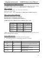
The symbol ↵ equates to a carriage return (decimal 13, hex 0x0D)
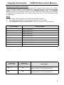
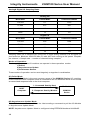
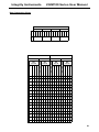
Host Command
Module Response
Action
T0000↵
T↵
All I/O lines are configured as Outputs
T00FF↵
T↵
All I/O lines are configured as Inputs
T000F↵
T↵
Port 2 bits 0-3 Inputs
Port 2 bits 4-7 Outputs
T00F0↵
T↵
Port 2 bits 0-3 Outputs
Port 2 bits 4-7 inputs
T0034↵
T↵
Port 2 bits 4,5,2 Inputs
Port 2 bits 7,6,3,1,0 Outputs
16