1
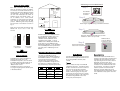
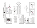
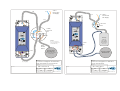
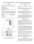
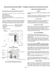
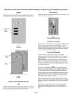
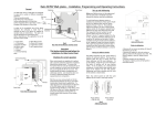
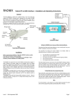
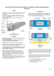
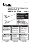
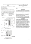
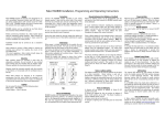
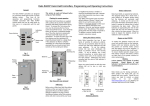
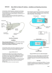
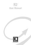
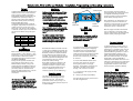
Rako Curtain, Blind and Screen Modules – Installation, Programming and Operating Instructions.
Before commencing installation of a Rako
RACUB module first read this instruction
manual carefully.
Rako Controls Ltd accepts no responsibility
for any damage or injury caused by
incorrect installation of a Rako product.
Scene
1
2
3
4
Off
Relay A
Closed
Open
Open
Closed
Open
Relay B
Closed
Closed
Open
Open
Open
Fig 1.
Default Settings
When wired correctly the default settings
will give Scene 2 = Open, Scene 3 = Stop
and Scene 4 = Close, this allows operation
from the Rako 3 and 6 button panels
specifically designed for blind and curtain
use (RPS03 and RPS06).
During normal operation the Raise and
Lower buttons have no effect on the
RACUB module; however, they can be
configured using the RASOFT software to
work as faders or as momentary controls,
particularly useful for Venetian blinds
which may need fine adjustment. See the
RASOFT documentation for more
information.
Note
For blind and curtain motor control both
relays should be used. This allows ‘neutral
state’ where no power is applied to either
coils of the motor, an in-built ‘delay on
changeover’ feature also avoids hard
reversing of a motor which can damage the
relays.
Installation should only be carried out by a
competent electrician.
Never attempt to connect a Rako module
or remove the terminal covers without first
isolating the circuit at the fuse/MCB
board.
The circuit supplying a Rako RACUB
module should always be protected by
either a 5A fuse or 6A MCB. Under no
circumstances should any protection
devices with higher ratings be used.
Clamping bar
B
The Rako RACUB curtain, blind and screen
modules allow control of most blind and
curtain motors from Rako transmitters.
Rako RACUB modules are designed to be
installed either separately or within a
lighting project and are controlled from
Rako scene-sender panels transmitting
Rako encoded radio signals.
The RACUB module provides 2 isolated
changeover relays which can be wired in a
number of ways to suit the motor type
being used. The relays can be configured
to be either closed or open in each of the 4
scenes but the default settings are given
below.
Mounting Holes
M
Installation
Once the supply and relay cables are
connected ensure that the terminal covers
are replaced and securely fastened,
clamping the cable correctly as detailed
above, before powering the unit.
A
General
Supply
Terminals
Fig 2.
Termination Area
Output
Terminals
Note
For the appropriate connection details for
control of motors for curtains, blinds and
screens always consult the motor
manufacturer’s instructions.
Rako modules are not designed for loop
in/loop out connections. Should it be
necessary to loop the supply on to further
fittings then a junction box should be
connected in circuit to facilitate this.
With the supply and load connected and
prior to switching on the supply ensure
that the terminal covers are fitted and that
they are securely clamping the cables.
Set-up and Addressing
Note:
Rako RACUB modules should be mounted
in areas that are adequately ventilated, dry
and outside of any enclosed metal casings.
Wherever possible the modules should be
securely fixed using the mounting holes
provided. The mounting holes are blanked
off when supplied but are designed so that
a woodscrew will easily cut through
without the need for drilling.
Whilst Rako modules are designed to be
completely maintenance free the units
should be mounted in a position where
access can be gained should there be a
fault or re-addressing of the unit be
necessary (see ‘Set-up and Addressing’).
Permissible loadings.
The relays are designed to be used for
either low or mains voltages but not a
combination of both. The maximum
permissible current is 2A per relay. If in
doubt contact the Rako customer help-line
on 01634 226666.
To ensure that the cable clamping operates
satisfactorily the cabling both supplying
the module and to the load should be a
minimum of 0.5mm with double safety
insulation and the wires should be stripped
to ensure that the cable bar within the
terminal cover clamps firmly on both sets
of insulation.
2
To install a Rako RACUB module isolate
the supply then remove the Terminal
Covers, giving access to the supply
terminals. The necessary connections are
indicated on the label on the dimmer
housing. The notation is as follows:
L – Live wire from the supply (normally
coloured Brown)
N – Neutral (normally coloured Blue)
The label indicates the relay connections in
their de-energised state.
To avoid interference between rooms or
neighbouring installations a Rako system
should be set to an address other than the
factory default of House 1 Room 4. The
preferred addressing method is to select a
logical House address number for the
project and separate Room addresses for
each room within the house. It may also
be desirable to give each RACUB an
individual channel address within the room
(see Fig.4) if separate control of each blind
or curtain motor is required (usually from
programmable remotes via infra-red or
centralised control systems via RS232).
Note
If the RACUB module is being installed in a
physical room with other Rako lighting
modules it may well be advisable to
Address the Lighting and RACUB modules
as separate ‘RAKO room numbers’ to allow
separate control of the blinds and lighting.
If this is the case then it is recommended
to use sequential room numbers as this
allows easier programming of a
programmable Infra Red remote at a later
stage.
Addressing From An RPS03 Panel
Setting the address switches.
Step 1
C hannel 1
C hannel 2
Blin ds
House 14 4
Room 7
Set address
switches on
controller
Lighting
House 14 4
Room 6
Step 2
Chan nel 2
Chan nel 1
House 14 4
Room 5
Note: Any control panels set with the same
address will act as two or multi way
controls.
144
Magnet
Each Rako transmitter has two, 8 way
banks of switches for setting its address.
The two sets of switches allow the user to
choose from 256 house addresses and 256
room addresses. To set the address, unclip
the rear cover whereupon the banks of
switches will be now become visible. To
set an address, use a small terminal
screwdriver or similar device and carefully
move some of the switches into the ‘ON’
position. Addressing uses binary encoding
and the value of the switches is shown in
Fig. 4.
Hold magnet against casing until LED illuminates
Fig 4.
Addressing Example
Step 3
House address
= 128+16=144
ROOM
128
64
32
16
8
4
2
1
ON
BINARY VALUE
HOUSE
128
64
32
16
8
4
2
1
ON
BINARY VALUE
To Set an Address.
Room address
= 32+4=36.
Fig 3.
Addressing Switches
Notes on addressing.
A RACUB will not receive an address of
House 0 (All switches set to off)
A RACUB will respond to, but not receive
an address of Room 0 (All switches set to
off). This Room 0 address is used for
‘Master House’ control
A RACUB cannot be set to channel 0.
To program a lighting scene see Wall panel
or Hand held manual.
RACUB modules can be addressed either
by a standard Rako RCP07 panel or an
RPS03/06 panel. Using an RCP07
individual channel addresses can be
assigned to each module. To set an
address from an RCP07 panel follow the
steps shown in ‘Initial Addressing of a
Rako Receiver Module’. To set an address
from and RPS03/06 control panel follow
the steps given in ‘Addressing from an
RPS03’.
Remove magnet when LED starts to flash
Module is now in set-up mode
LED flashes to
confirm address
command is sent
Step 4
Press and hold both
buttons for 5 seconds
Programming RACUB units from an RCP07
The relays in a RACUB unit can be
programmed using an RCP07 wallplate or
from RASOFT software. To program the
relay settings follow the wallplate
instructions for programming a scene.
Program the RACUB as though the level
was being set in a dimming module, the
way that the relays respond is given below.
Level
Relay A
Relay B
76-100%
Closed
Closed
51-75%
Open
Closed
26-50%
Closed
Open
0-25%
Open
Open
Special Features.
The Rako RACUB module has some in-built
features and some special features that can
be set using RASOFT software, these
include.
Timeout
After 5 minutes the relays in the RACUB
module will both open. This feature allows
blinds or curtains time to travel to their full
extent but not be left with permanent
power on. If a blind/curtain motor is miswired or wired using only one relay then
this feature can cause the motor to reverse
after the time-out period. The timeout can
be disabled using RASOFT but correct
wiring is the preferred option.
Momentary Action
This feature enables the RACUB unit to
respond to the raise/lower commands from
an RCP07 wall panel and with the motor
only operating all the time that a button is
depressed. If the latch after box is
checked then after the set period of time
the button can be released and the motor
will still operate. This feature is primarily
used for operation of Venetian blinds
where the tilt angle needs to be set by
small adjustments but latching after a short
time is desirable to fully open or close the
blinds.
Step 3
TABLE 1
Action
Step up one channel and ident
Step down one channel and ident
Ident
No action
Exit programming
Hold the
magnet against casing at point indicated
on the label until LED illuminates and keep the
magnet held with the LED on until it starts to
flash. Then remove magnet. Module is now in
set-up mode.
Note: If a receiver is already addressed to a
controller (for example a receiver is addressed to
the controller but with the wrong channel number)
then the LED will be flashing as soon as the panel
is put into programming mode. It will, however,
still be possible to re-address this receiver using
the magnet as normal.
Step 4
Go to the receiver to be addressed
Step 2
TIP
Press the
scene button first
Note
Step 5
Press Off button
to exit controller
from programming
mode
Step 6
Is there
another receiver in
the room to be
addressed
YE S
NO
To add a new receiver to an existing installation step up through
the channels to an available channel number. It is possible to tell which
channels modules are addressed to by looking at the LED in the module.
When the channel address for a module is reached, instead of pulsing the
LED will momentarily go solid.
YE S
Note:
When in programming mode the buttons have functions as
detailed in table 1.
Note:
A Rako panel will always enter programming mode at Channel 0.
It is not possible to give a receiver an address of Channel 0 but
this gives a consistent starting point.
Put controller into
programming mode
by pressing and holding
a scene button and both
raise and lower buttons
together. After 5 seconds
the red LED on the panel
starts to flash. The panel
is now in programming
mode. Release the buttons
Press button 3
to send the ident
of the channel
selected in step 3.
Receiver automatically
returns to normal mode
(blue LED goes out)
while controller remains
in programming mode
(red LED keeps flashing)
Press button 1 once to step up one channel.
If this is the desired channel i.e. Channel 1(for the 1st receiver)
then go to Step 4. If not, press button 1 again to step up to
channel 2 (for the 2nd receiver), again to step to channel 3 etc,
until the d esired channel number is reached (maximum = 15).
It is this channel number (along with the House and Room address)
that is sent to the receiver in Step 5. If at any point it is necessary to
step down a channel, press button 2 once.
Button
1
2
3
4
Off
Pick an House address from 1-255
(keep same address for all panels in house)
Select Room addresses from 1-255 for each
room (Room 0 is master house control)
Set address
switches on
controller
Step 1
Is the
controller
still in programming
mode (red LED
flashing)
NO
Note:
In the following procedure both the controllers (wallpanels and hand held remotes) and the receivers have an automatic time out after approximately 3 minutes when
in programming or set-up mode. This feature avoids the possibility of either being left permanently in programming or set-up mode. This may cause confusion if
either the controller or receiver times out before the procedure is complete. It is worth becoming familiar with the procedures before starting the addressing procedure.
If at any time it is necessary to start again the controllers can be returned to normal mode by pressing the ‘Off’ button and the receivers by resetting the electrical supply.
Initial Addressing of a Rako Receiver Module
L,N
N
240 v
Protected
6A Suppy
L
L,N
L
N
N
NL
SUPPLY
INPUT VOLTAGE
220-240V
50Hz
Black
N
(1)
L
C URTAIN S CR EE N A ND
BLI ND CO N TRO L U N IT
4 Way
Junction
Box
(2)
N
L
Junction
Box
L
N
L,N
NL
SUPPLY
INPUT VOLTAGE
220-240V
50Hz
C URTAIN S CR EE N A ND
BLI ND C ON TRO L U N IT
Brown
M
Blue
Somfy
MAXIM UM LO AD
2 A PER REL AY
A
240v to
12v or 24v
DC Supply
B
Note
M
Do not co nnect tw o
motors in para llel (use
tw o RACUB units)
MAXIM UM LO AD
2 A PER REL AY
A
240 v
Protected
6A Suppy
L
B
Links
(De pendant o n
the motor)
Blue
Brown
Black
Link
L
Somfy 240V
Blind Motor
(1) (2)
L, (1), (2)
Somfy 24vDC
Blind Motor
(Blue, Brown, Blac k Cab le
Conne ctions)
Drawing Title
Drawing Title
Connection Diagram For RACUB to
240v Somfy Blind / Screen Motor
Connection Diagram For RACUB to
L.V. DC Somfy Motor
Drawing N o
Drawing N o
Notes
RD 1005 Rev A
Drawn
Ch ecked
DA
AG
Scale
Date
Notes
NTS
18/3/05
Tel 0870 043 3905 Fax 0870 043 3906
RD 1007 Rev A
Drawn
Ch ecked
www.rakocontrols.com
DA
AG
Scale
Date
NTS
18/3/05
Tel 0870 043 3905 Fax 0870 043 3906
www.rakocontrols.com