1
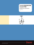
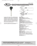
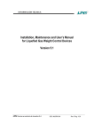
Easidew I.S. Dew-Point Transmitter User’s Manual Kahn Instruments, Inc. 2015 This document is the property of Kahn Instruments and may not, either in part or whole, be copied or otherwise reproduced, communicated in any way to third parties nor stored in any data processing system, without the written authority of Kahn Instruments, Inc. Easidew I.S. For Kahn Instruments' contact information please go to www.kahn.com © 2015 Kahn Instruments This document is the property of Kahn Instruments, Inc. and may not be copied or otherwise reproduced, communicated in any way to third parties, nor stored in any Data Processing System without the express written authorization of Kahn Instruments, Inc. Easidew I.S. User’s Manual Contents Safety.................................................................................................................................vi Electrical Safety............................................................................................................vi Pressure Safety.............................................................................................................vi Toxic Materials..............................................................................................................vi Repair and Maintenance................................................................................................vi Calibration....................................................................................................................vi Safety Conformity.........................................................................................................vi Abbreviations......................................................................................................................vii Warnings............................................................................................................................vii 1INTRODUCTION.................................................................................................1 1.1Features............................................................................................................. 1 2INSTALLATION...................................................................................................2 2.1 2.2 2.3 2.4 2.4.1 2.5 2.5.1 2.5.2 2.5.3 Unpacking the Instrument.................................................................................... 2 Preparation of the Sensor Cable........................................................................... 3 Cable Connection................................................................................................ 5 Electrical Schematic............................................................................................. 5 Electrical Boundaries...................................................................................... 6 Transmitter Mounting........................................................................................... 6 Transmitter Mounting - Sample Block (Optional)............................................... 7 Transmitter Mounting - Direct Pipeline Connection............................................ 8 Transmitter Mounting - With Additional Process Connection Adapter ................. 9 3OPERATION.....................................................................................................10 4MAINTENANCE.................................................................................................11 4.1 O-Ring Replacement.......................................................................................... 12 Figures Figure Figure Figure Figure Figure Figure Figure Figure Figure Figure Figure Figure Figure Figure Figure Figure Figure Figure 1 2 3 4 5 6 7 8 9 10 11 12 13 14 15 16 17 18 Transmitter Unpacking Method.....................................................................2 Connector Terminal Block Removal...............................................................3 Bare Wires..................................................................................................3 Crimped Wires............................................................................................3 Cut to 5mm................................................................................................4 Connection to Connector Terminal Block........................................................4 Wiring Connections......................................................................................4 Connector Installation..................................................................................5 2-Wire Connection Diagram..........................................................................5 Electrical Connections..................................................................................5 Maximum Load of Easidew - Including Cable Resistance.................................6 Transmitter Mounting...................................................................................7 Transmitter Mounting - Pipe or Duct.............................................................8 Transmitter Mounting with Adapter ..............................................................9 Installation Location..................................................................................10 Indication of Dead Space...........................................................................10 Replacement of HDPE Guard......................................................................11 Dimensions ..............................................................................................15 Kahn Instruments 3 Easidew I.S. User’s Manual Appendices Appendix A Technical Specifications .............................................................................. 14 A.1Dimensions.................................................................................. 15 Appendix B System B.1 B.2 B.3 Appendix C Hazardous Area Certification....................................................................... 21 C.1 Product Standards........................................................................ 21 C.2 Product Certification..................................................................... 21 C.3 Global Certificates/Approvals......................................................... 21 C.4 Terminal Parameters..................................................................... 21 C.5 Special Conditions of Use.............................................................. 22 C.6 Maintenance and Installation......................................................... 22 Appendix D EC Declaration of Conformity....................................................................... 24 Drawings........................................................................................ 17 Baseefa Approved System Drawing................................................ 17 FM Approved System Drawing....................................................... 18 CSA Approved System Drawing...................................................... 19 4 97099 Issue 13.4, August 2015 Easidew I.S. User’s Manual Safety The manufacturer has designed this equipment to be safe when operated using the procedures detailed in this manual. The user must not use this equipment for any other purpose than that stated. Do not apply values greater than the maximum value stated. This manual contains operating and safety instructions, which must be followed to insure the safe operation and to maintain the equipment in a safe condition. The safety instructions are either warnings or cautions issued to protect the user and the equipment from injury or damage. Use competent personnel using good engineering practice for all procedures in this manual. Electrical Safety The instrument is designed to be completely safe when used with options and accessories supplied by the manufacturer for use with the instrument. Pressure Safety DO NOT permit pressures greater than the safe working pressure to be applied to the instrument. The specified safe working pressure is 6500 psig (450 barg / 45 MPa). Refer to the Technical Specifications in Appendix A. Toxic Materials The use of hazardous materials in the construction of this instrument has been minimized. During normal operation it is not possible for the user to come into contact with any hazardous substance which might be employed in the construction of the instrument. Care should, however, be exercised during maintenance and the disposal of certain parts. Repair and Maintenance The instrument must be maintained by Kahn Instruments, Inc.. Refer to www.kahn.com for contact details. Calibration The recommended calibration interval for this instrument is 12 months unless it is to be used in a mission-critical application or in a dirty or contaminated environment in which case the calibration interval should be reduced accordingly. The instrument should be returned to the manufacturer, Kahn Instruments Inc., or one of their accredited service agents for re-calibration. Safety Conformity This product meets the essential protection requirements of the relevant US and European standards and directives. Further details of applied standards may be found in the Technical Specifications in Appendix A. Kahn Instruments 5 Easidew I.S. User’s Manual Abbreviations The following abbreviations are used in this manual: barg °C °F DC dp fps ft-lbs g lbs/in µm m/sec mA max mm MPa Nl/min Nm oz ppmV psig RH scfh V Ω ø “ pressure unit (=100 kP or 0.987 atm) (bar gauge) degrees Celsius degrees Fahrenheit direct current dew point feet per second feet per pounds grams pounds per inch micrometer meters per second milliampere maximum millimetres megapascal normal liters per minute Newton meter ounces parts per million by volume pounds per square inch relative humidity standard cubic feet per hour Volts Ohms diameter inch(es) Warnings The following general warning listed below is applicable to this instrument. It is repeated in the text in the appropriate locations. Where this hazard warning symbol appears in the following sections it is used to indicate areas where potentially hazardous operations need to be carried out. 6 97099 Issue 13.4, August 2015 Easidew I.S. User’s Manual 1 INTRODUCTION INTRODUCTION The Easidew I.S. dew-point transmitter has been manufactured, tested and calibrated to the highest available standards and should be in perfect working order, ready for installation into a gas measurement application. If, after reading this manual, there are any questions about the instrument or how to install and operate it, please contact Kahn Instruments. Inc. Refer to www.kahn.com for contact details. This manual covers the following Easidew I.S. (Intrinsically Safe) dew-point products: Easidew I.S. with 5/8” UNF thread Easidew I.S. with 3/4” UNF thread Easidew I.S. with G 1/2” BSP thread 1.1 Features The Easidew I.S. dew-point transmitter is a continuous, on-line, 4-20 mA transmitter for the measurement of dew-point temperature or moisture content in air and other non-corrosive gases. It is designed specifically for use within Zone 0, 1 and 2 hazardous areas. The key features are: • IECEx, CSA, FM, ATEX certified transmitter for use in hazardous areas • 5/8” or 3/4” UNF, G1/2” BSP, process connection • Dew-point or ppmV moisture content • 2-wire loop powered connection • Rugged 316 stainless steel IP66 construction • Measurement ranges-148 to +68°Fdp (-100 to +20°Cdp) -166 to +68°Fdp (-110 to +20°Cdp) • Accuracy ±2°Cdp • Calibration Certificate (NPL, NIST) Kahn Instruments 1 Easidew I.S. User’s Manual INSTALLATION 2 INSTALLATION 2.1 Unpacking the Instrument On delivery, check that all the following standard components are in the packing tube: • Easidew I.S. Transmitter 5/8” UNF and G 1/2” BSP version - Bonded seal fitted over threaded part of transmitter body OR 3/4” UNF version - Recessed sensor O-ring seal • Quantity 3 cable crimps • Sensor connector • Packing tube, and foam protectors (not needed for operation - save all the packing materials for the purpose of returning the instrument for recalibration or any warranty claims) • Certificate of calibration NOTE: If any component is not present in the packing box, contact Kahn Instruments immediately. Unpack the dew-point transmitter packing tube as follows (see Figure 1). G 1/2“ BSP (black) 1 2 3 4 5 Figure 1 6 7 8 9 3/4” UNF (green) 5/8” UNF (blue) Transmitter Unpacking Method 1. Unscrew the cap (1) from the packing tube (9). 2. Remove the bag containing 3 cable crimps (2). 3. Remove the foam block (4) containing the connector (3). 4. Pull out the transmitter (6) from the tube, complete with the two foam covers (7) and (8) and the red protective cap (5). 5. Remove the foam covers from the transmitter but leave the green, blue or black plastic protective cover (6) and the red cap (5) in place until ready for installation. NOTE: The transmitter sensing element is protected while in transit by a black, green or blue cover containing a small desiccant capsule. The connection pins are protected by a red plastic cap. None of these plastic items are required for the operation of the transmitter. NOTE: Keep the connector (3) in a safe place until the transmitter is ready for wiring. 2 97099 Issue 13.4, August 2015 INSTALLATION Easidew I.S. User’s Manual 2.2 Preparation of the Sensor Cable The sensor cable is NOT supplied as standard. A cable can be obtained by contacting Kahn Instruments (see www.kahn.com for details). The crimps supplied must be fitted onto any cable installed into the connector in order to comply with Hazardous Area Certification of the product. If making a cable assembly it is important that the cable is correctly terminated. See Figures 3 to 6. Cable connection to the Easidew I.S. transmitter is made via the removable connector. Removing the central screw enables the connector terminal block to be removed from the outer housing by using a small screwdriver to pry it off. O-ring and washer Figure 2 Connector Terminal Block Removal Caution: When removing the central screw insure that the small sealing O-ring and the washer are retained on the screw and are present during re-installation. NOTE: Figure 3 to Figure 6 shown below, should be followed in detail. The crimps should be applied such that there is no possibility of a conductor strand of a core becoming free (see Figure 4). Figure 3 Bare Wires Figure 4 Crimped Wires Kahn Instruments 3 Easidew I.S. User’s Manual INSTALLATION When the crimp is made it should have a minimum of 2 positions of crimping. After the crimp is made it should be trimmed to a length of 5mm (see Figure 5). When the crimps are installed into the connector terminal block insure they are fully inserted, as shown in Figure 6, before tightening the terminal clamping screw. 1 3 4 mm 10 Figure 5 2 Cut to 5mm Connection to Connector Terminal Block Figure 6 When all wire connections are made, insure that there is a minimum clearance distance and a minimum creepage distance in air of 0.8” (2mm) between each terminal. For the transmitter to work properly, and to achieve maximum performance, the sensor cable must be connected to the sensor connector as shown in the drawing below. Note: The drawing below shows the identity of the connector terminals and wiring connections of the cable supplied by Kahn Instruments. GN RD BL 1 BLUE GND 2 4 SCREEN GREEN YELLOW BLUE RED BRAID RED +POWER 3 BRAID GREEN SIGNAL (SOURCE) SHORT AS POSSIBLE GREEN - 4-20 mA RED + POWER BLUE - SCREEN GREEN - 4-20 mA (SOURCE) BLUE - SCREEN RED + POWER VIEW ON REAR OF CONNECTOR SCALE 2:1 Figure 7 Wiring Connections Always connect the 4-20 mA return signal to a suitable load (see Figure 7) before the power is applied. Without this connection, the transmitter may be damaged if allowed to operate for prolonged periods. 4 97099 Issue 13.4, August 2015 INSTALLATION Easidew I.S. User’s Manual 2.3 Cable Connection When installing the connector, and to insure that full ingress protection is achieved, the securing screw (with the O-ring and washer) must be tightened to a minimum torque setting of 3.4 Nm (2.5 ft-lbs). The sensor cable used must be a minimum diameter of 4.6mm (0.2”). O-ring and washer Connector Installation Figure 8 2.4 Electrical Schematic NOTE: The screen/shield should be connected for maximum performance and to avoid interference. 3 1 + Screen/ Shield Max Load 250R @ 12V 500R @ 24V Supply 12V Min 28V Max 2-Wire Connection Diagram Figure 9 GALVANIC ISOLATION INTERFACE HAZARDOUS AREA SAFE AREA KFD2-STC4-Ex1 H TRANSMITTER VERSION TERMINAL NUMBER DEW-POINT TRANSMITTER CERTIFICATION No’s: Baseefa06ATEX0330X IECEx BAS 06.0090X EASIDEW I.S. 3 1 KFD0-CS-Ex2.50p KFD2-CR-Ex1.20200 (+) (+) (RETURN) (-) KFD2-CR-Ex1.30200 + 4-20 mA LOAD - KFD0-CS-Ex1.50P MTL5041 +VS (20 - 35 V DC) VS - MTL5040 MTL5541 Figure 10 Electrical Connections Kahn Instruments 5 Easidew I.S. User’s Manual INSTALLATION 2.4.1 Electrical Boundaries Resistance (ohms) 600 500 400 300 200 100 12 14 16 18 20 22 24 26 28 Supply Voltage Figure 11 2.5 Maximum Load of Easidew - Including Cable Resistance Transmitter Mounting Prior to installation of the transmitter, unscrew and remove the black, green or blue plastic cover and retain for future use. Take care to prevent any contamination of the sensor before installation (handle the transmitter by the main body only, avoiding contact with the sensor guard). The Easidew I.S. can be mounted either into a flow-through sensor sampling block (optional) or directly into a pipe or duct. It can be operated at pressures of up to 6500 psig (450 barg / 45 MPa) when fitted with the bonded seal or O-ring provided. The recommended gas flow rate, when mounted in the optional sampling block, is 2.1 to 10.6 scfh (1 to 5 Nl/min). However, for direct insertion applications, gas flow can be from static to 32.8 fps (10 m/sec). NOTE: Pass the seal over the mounting thread and assemble into the sampling location, by hand, using the wrench flats only. DO NOT grip and twist the sensor cover when installing the sensor. When installed, fully tighten using a wrench until the seal is fully compressed and to the following torque settings: • 5/8” - 18 UNF 22.5 ft-lbs (30.5 Nm) • 3/4” - 16 UNF 40 Nm (29.5 ft-lbs) • G 1/2” BSP 56 Nm (41.3 ft-lbs) 6 97099 Issue 13.4, August 2015 INSTALLATION Easidew I.S. User’s Manual 2.5.1 Transmitter Mounting - Sample Block (Optional) The following procedure must be carried out by a qualified installation engineer. To mount the transmitter into the sensor block (preferred method), proceed as follows, refer to Figure 12. 1. Insure that the green, blue or black protective cover (2), and its desiccant capsule (2a), have been removed from the tip of the transmitter. 2. G 1/2” and 5/8” Versions - Insure that the bonded seal (2) is over the threaded part of the transmitter body. 3/4” Version - Insure the O-ring is fully seated in the recess. Under no circumstances should the sensor guard be handled with the fingers. 3. Screw the transmitter (1) into the sample block (3) and tighten to the appropriate torque setting (see Section 2.5). NOTE: Use the flats of the hexagonal nut and not the sensor body. 4. Fit the transmitter cable/connector assembly to the plug located on the base of the transmitter and tighten the securing screw (see Section 2.3). 2 2a 4 1 3 4 Figure 12 Transmitter Mounting 5 Kahn Instruments 7 Easidew I.S. User’s Manual INSTALLATION 2.5.2 Transmitter Mounting - Direct Pipeline Connection The transmitter may be directly mounted into a pipe or duct as shown in Figure 13. Caution: Do not mount the transmitter too close to the bottom of a bend where any condensate in the pipeline might collect and saturate the probe. The pipe or duct will require a thread to match the transmitter body thread. Mounting dimensions are shown in Figure 13. For circular pipework, to insure the integrity of a gas tight seal, a mounting flange will be required on the pipe or tubing in order to provide a flat surface to seal against. The following procedure must be carried out by competent personnel. 1. Insure that the protective cover (and its desiccant capsule) has been removed from the tip of the transmitter. WARNING: Under no circumstances should the sensor guard be handled with the fingers. 2. G 1/2” and 5/8” Versions - Insure that the bonded seal (2) is over the threaded part of the transmitter body. 3/4” Version - Insure the O-ring is fully seated in the recess. 3. Screw the transmitter (3) into the pipe (1). Tighten enough to obtain a gas tight seal. NOTE: Do not overtighten or the thread on the pipe or tubing may be stripped. 2 1 3 2 3 14 15 4 5 6 16 17 18 7 18 10 11 8 9 22 23 20 21 Optional display (available on request) 1 Optional cable (available on request) 48mm (1.9”) 2 3 Figure 13 Transmitter Mounting - Pipe or Duct Fig 03.13 (PP 24) 8 97099 Issue 13.4, August 2015 INSTALLATION Easidew I.S. User’s Manual 2.5.3 Transmitter Mounting - With Additional Process Connection Adapter Applicable to the Easidew I.S. 5/8” Version ONLY The following procedure must be carried out by a qualified installation engineer. To mount the adapter into the transmitter, proceed as follows (see Figure 14) : 1. Insure that the protective cover (2), and its desiccant capsule (2a), have been removed from the tip of the transmitter. 2. Place the bonded seal (3) over the threaded part of the transmitter body. 3. Screw the adapter (4) onto the threaded part of the transmitter and tighten to 22.5 ft-lbs (30.5 Nm). NOTE: Use the flats of the hexagonal nut and not the sensor body. WARNING: Under no circumstances should the sensor guard be handled with the fingers. 4. Screw the transmitter (1) with its seal (3) and adapter (4) into the sample block (see Section 2.5.1 or see Section 2.5.2) and fully tighten using a wrench until the seal is fully compressed and to the following torque settings: G 1/2” BSP 41.3 ft-lbs (56 Nm) 3/4” - 16 UNF ` 29.5 ft-lbs (40 Nm) 1/2” NPT Use a suitable sealant e.g. PTFE tape using correct taping procedures NOTE: Use the flats of the hexagonal nut and not the sensor body. 2 2a 1 Figure 14 4 3 Transmitter Mounting with Adapter Kahn Instruments 9 Easidew I.S. User’s Manual OPERATION 3 OPERATION Operation is very simple, assuming the following installation techniques are adhered to: Sampling Hints Be Sure the Sample is Representative of the Gas Under Test: The sample point should be as close to the critical measurement point as possible. Also, never sample from the bottom of a pipe as entrained liquids may be drawn into the sensing element. Figure 15 Installation Location Minimize Dead Space in Sample Lines: Dead space causes moisture entrapment points, increased system response times and measurement errors, as a result of the trapped moisture being released into the passing sample gas and causing an increase in partial vapor pressure. Deadspace Figure 16 Indication of Dead Space Remove Any Particulate Matter or Oil from the Gas Sample: Particulate matter at high velocity can damage the sensing element and similarly, at low velocity, they may ‘blind’ the sensing element and reduce its response speed. If particulate, such as degraded desiccant, pipe scale or rust is present in the sample gas, use an in-line filter, as a minimum level of protection. For more demanding applications Kahn Instruments offers a range of sampling systems (for more information contact www.kahn.com). Use High Quality Sample Tube and Fittings: Kahn Instruments recommends that, wherever possible, stainless steel tubing and fittings should be used. This is particularly important at low dew points since other materials have hygroscopic characteristics and adsorb moisture on the tube walls, slowing down response and, in extreme circumstances, giving false readings. For temporary applications, or where stainless steel tubing is not practical, use high quality thick walled PTFE tubing. Position Transmitter away from Heat Source: It is recommended, as good instrumentation practice, that the transmitter is placed away from any heat source to avoid adsorption/desorption. 10 97099 Issue 13.4, August 2015 Easidew I.S. User’s Manual 4 MAINTENANCE MAINTENANCE Calibration Routine maintenance of the Easidew I.S. is confined to regular re-calibration by exposure of the transmitter to sample gases of known moisture content to insure that the stated accuracy is maintained. Calibration services traceable to the US National Institute of Standards and Technology (NIST) are provided by Kahn Instruments. Kahn Instruments offers a variety of re-calibration and service exchange schemes to suit specific needs. A Kahn representative can provide detailed, custom advice (refer to www.kahn.com for details of Kahn Instruments’ contact information). The following procedure must be carried out by a qualified installation engineer. Sensor Guard Replacement The sensor is supplied with either a white HDPE or a stainless steel guard. The method of replacement is the same for both types. HDPE Guard The HDPE guard provides <10μm protection to the dew-point sensor. It is designed to show any contamination and the guard should be changed if the surface becomes discolored. When replacing the guard, care should be taken to handle the guard by the bottom part only. Replacement guards (EA2-HDPE) - pack of 10 - can be obtained by contacting Kahn Instruments (www.kahn.com) or your local distributor. HANDLE, USING GLOVES, BY BLACK PART ONLY m it te r 09 06 ew Ra 34 ng e: n s 0 a 0 -1 +2 Tr 0 / 6 3N s id Replacement of HDPE Guard CB Figure 17 Ea Stainless Steel Guard The stainless steel guard provides <80μm protection to the dew-point sensor. It is designed to show any contamination and the guard should be changed if the surface becomes discolored. When replacing the guard, care should be taken to handle the guard by the bottom part only. A replacement guard (SSG) can be obtained by contacting Kahn Instruments (www.kahn.com). Kahn Instruments 11 Easidew I.S. User’s Manual MAINTENANCE Bonded Seal If the installed bonded seal gets damaged or lost, a pack of 5 replacement bonded seals (1/2-BS (for G 1/2 -BSP) or 5/8-BS (for 5/8” -18 UNF)) can be obtained by contacting Kahn Instruments, or your local distributor. 4.1 O-Ring Replacement If the installed O-ring gets damaged or lost, a pack of 5 replacement O-rings (3/4OR (for 3/4” - 16 UNF)) can be obtained by contacting Kahn Instruments. Do not touch the filter with bare hands 1. Identify the O-ring to be removed, as shown below. BS116 (3/4” x 3/32”) viton, 75 shore 2. Carefully slide tweezers, thin bladed screwdriver or a blunt needle under the outer edge of the O-ring. NOTE: Take care not to scratch any of the surfaces of the surrounding metal component. 3. Move the tool around the circumference to assist the extraction process. Slide the O-ring clear of the thread and filter. 4. Make sure the groove has no scratches and is free from grease, dirt or debris. Slide the new O-ring over the filter and thread and into the groove. NOTE: Do not touch the filter with bare hands. 12 97099 Issue 13.4, August 2015 Easidew I.S. User’s Manual APPENDIX A Appendix A Technical Specifications Kahn Instruments 13 Easidew I.S. User’s Manual APPENDIX A Appendix A Technical Specifications Performance Measurement Range (dew point) Accuracy (dew point) Repeatability Response Time Calibration -148 to +68°Fdp (-100 to +20°Cdp) -166 to +68°Fdp (-110 to +20°Cdp) ±3.6°Fdp (±2°Cdp) 0.9°Fdp (0.5°Cdp) 5 mins to T95 (dry to wet) 13-point calibration with traceable 7-point calibration certificate Electrical Specifications Output Signal Output Analog Output Scaled Range Supply Voltage Load Resistance Current Consumption CE Marked 4-20 mA (2-wire connection current source) User-configurable over range Dew point or moisture content for ppmV Dew point: -148 to +68ºF (-100 to +20ºC) OR Moisture content in gas: 0 - 3000 ppmV Non-standard available upon request 12 to 28 V DC Max 250 Ω @ 12 V (500 Ω @ 24 V) 20 mA max Certified Operating Specifications Operating Temperature Operating Pressure Flow Rate Temperature Coefficient -40 to +158ºF (-40 to +70ºC) 6500 psig (450 barg / 45 MPa) max Qualified over-pressure rating: (2 x operating pressure) 13053 psig (900 barg / 90 MPa) 2.1 to 10.6 scfh (1 to 5 Nl/min) mounted in standard sampling block 0 to 32.8 fps (0 to 10 m/sec) direct insertion Temperature compensated across operating temperature range Mechanical Specifications Ingress Protection Housing Material Dimensions Sensor Guard Process Connection & Material Weight Interchangeability Electrical Connection Diagnostic Conditions (factory programmed) NEMA 4 in protection accordance with standard NEMA 250-2003 IP66 in accordance with standard BS EN60529:1992 316 stainless steel Transmitter plus connector: L=5.19” x ø 1.77” (132mm x ø 45mm) Standard: HDPE Guard < 10µm Optional: 316 stainless steel sintered guard < 80µm G 1/2” BSP; 3/4” - 16 UNF; 5/8” - 18 UNF Material - 316 stainless steel 5.29oz (150g) Fully interchangeable transmitter Hirschmann GDS series (DIN 4350-C) Condition Output Sensor fault 23 mA Under-range dew point 4 mA Over-range dew point 20 mA 14 97099 Issue 13.4, August 2015 APPENDIX A Easidew I.S. User’s Manual KFD2-CR-EX1.20200 KFD2-CR-EX1.30200 KFD0-CS-EX1.50P Approved Galvanic Isolators KFD0-CS-EX2.50P KFD2-STC4-EX1.H MTL5041, MTL5040 Hazardous Area Certification ATEX II 1G Ex ia IIC T4 Ga (-20°C to IECEx Ex ia IIC T4 Ga (-20°C to TC TR Ex 0Ex ia IIC T4 Ga (-20°C to FM Class I, Division 1, Groups A B C CSA Class I, Division 1, Groups A B C Certification Codes Dimensions SENSOR G1/2” BSP Bonded Seal 132mm (5.19”) 27mm (1.06”) A/F 10mmø27mm (0.39”) (1.06”) 45mm (1.77”) 46mm (1.81”) A.1 +70°C) +70°C) +70°C) D, T4 D, T4 G1/2” BSP 10mm (0.39”) ø28.65 x 2.61mm (ø1.12 x 0.10”) G1/2” Process Connection SENSOR 3/4” - 16 UNF O-Ring 27mm (1.06”) A/F 10mmø27mm (0.39”) (1.06”) 45mm (1.77”) 46mm (1.81”) 132mm (5.19”) 3/4” UNF ø18.72 x 2.62mm (ø0.75 x 0.09”) 10mm (0.39”) 3/4” Process Connection SENSOR 5/8” - 18 UNF Bonded Seal 46mm (1.81”) 27mm (1.06”) A/F 10mmø27mm (0.39”) (1.06”) 45mm (1.77”) 132mm (5.19”) 5/8” UNF 10mm (0.39”) ø25.4 x 2mm (ø1 x 0.07”) 5/8” Process Connection Figure 18 Dimensions Kahn Instruments 15 APPENDIX B Easidew I.S. User’s Manual Appendix B System Drawings 16 97099 Issue 13.4, August 2015 Easidew I.S. User’s Manual Appendix B B.1 APPENDIX B System Drawings Baseefa Approved System Drawing Kahn Instruments 17 33mH 12.6 mH 4.2mH 2.11 F 613 nF 46 nF D C AB OR 435 H/ 217 H/ 54 H/ L/R RATIO ( H/ohm) MICHELL INSTRUMENTS LTD. 01/11/05 DOF03 DEWPOINT TRANSMITTER CERTIFICATION No's: Baseefa06ATEX0330X IECEX BAS 06.0090X 4 1 4 Inches 100mm MTL5041 BAS 01 ATEX 7155 (-) DATE 10/03/06 MSB DATE CHECKED DATE APPROVED DIMENSIONS: TOLERANCES: VS - mm DRAWING UNITS MICHELL INSTRUMENTS LTD. CAMBRIDGE © NTS SCALE +VS (20 TO 35V DC) LOAD +0.1 HOLE Ø: -0.0 ANGLES: ±0.5° FINISH 0 DEC. PLACE: ± 0.5 1 DEC. PLACE: ± 0.2 2 DEC. PLACE: ± 0.1 UNLESS OTHERWISE STATED - + 4/20mA EASIDEW I.S. DEWPOINT TRANSMITTER FM SYSTEM DRAWING USED ON TITLE MATERIAL 3rd ANGLE PROJECTION KFDO-CS-Ex2.50P BAS98ATEX7343 000 MTL5040 BAS 98 ATEX 2227 000 000 KFD0-CS-Ex1.50P BAS 98 ATEX 7343 (+) 000 KFD2-CR-Ex1.30200 BAS 00 ATEX 7164 000 KFD2-CR-Ex1.20200 BAS 00 ATEX 7164 NON-HAZARDOUS LOCATION THIS DOCUMENT IS THE PROPERTY OF MICHELL INSTRUMENTS LTD. AND MUST NOT BE COPIED NOR DISCLOSED TO A THIRD PARTY WITHOUT THE CONSENT OF MICHELL INSTRUMENTS. (RETURN) (+) DRAWN 2 3 3 EASIDEW PRO I.S. EASIDEW I.S. TRANSMITTER VERSION TERMINAL NUMBER HAZARDOUS LOCATION CLASS 1, DIVISION 1, GROUPS A,B,C, & D THE CAPACITANCE AND THE INDUCTANCE OF TEH HAZARDOUS AREA CABLES MUST NOT EXCEED THE VALUES GIVEN IN TABLE 1. THE INSTALLATION MUST COMPLY WITH THE INSTALLATION PRACTICES OF THE COUNTRY OF USE, i.e. ANSI/ISARP12.6(INSTALLATION OF INTRINSICALLY SAFE SYSTEMS FOR HAZARDOUS [CLASSIFIED] LOCATIONS) AND THE NATIONAL ELECTRICAL CODE ANSI/NFPA 70. THE ISOLATION OF THE SIGNAL WIRES WITH THE EASIDEW DISCONNECTED, MUST BE ABLE TO WITHSTAND A 500V AC INSULATION TEST. INDUCTANCE (mH) CAPACITANCE ( F) SHEET 1 OF 1 A3 Ex90385 SIGN DATE DRAWING NUMBER IMA 16/07/07 CERT ISS IMA ISSUE MOD. No. 21/01/09 IMA IMA IMA 01 06/04/11 24/03/09 23/12/08 CERT ISS CERT ISS 03 02 11081 CERT ISS 05 04 B.2 GROUP THE CAPACITANCE AND EITHER THE INDUCTANCE OR THE INDUCTANCE TO RESISTANCE RATIO (L/R) OF THE CABLE MUST NOT EXCEED THE FOLLOWING VALUES: APPENDIX B Easidew I.S. User’s Manual FM Approved System Drawing 18 97099 Issue 13.4, August 2015 4.2mH 12.6 mH 33mH 46 nF 613 nF 2.11 F AB C D OR 54 H/ 217 H/ 435 H/ L/R RATIO ( H/ohm) Kahn Instruments 4/20mA MICHELL INSTRUMENTS LTD. 01/11/05 DOF03 +VS (20 TO 35V DC) VS - LOAD - + (-) (+) CSA Certified Barrier 4 Inches 100mm NON-HAZARDOUS LOCATION (+) 3 4 2 1 3 EASIDEW I.S. DATE DRAWN 10/03/06 MSB DATE CHECKED DATE APPROVED < V max, ISC < IMAX, Ca> Ci + CCABLE, La > Li + LCABLE DIMENSIONS: TOLERANCES: +0.1 HOLE Ø: -0.0 ANGLES: ±0.5° FINISH 0 DEC. PLACE: ± 0.5 1 DEC. PLACE: ± 0.2 2 DEC. PLACE: ± 0.1 UL Canada E106378CUL BAS99ATEX7060 UL Canada E106378CUL BAS00ATEX7164 BAS00ATEX7164 UL Canada E106378CUL UNLESS OTHERWISE STATED Smart Transmitter Power Supply Transmitter Supply Isolator Transmitter Supply Isolator UL Canada E106378CUL BAS98ATEX7343 MICHELL INSTRUMENTS LTD. CAMBRIDGE © mm DRAWING UNITS NTS SCALE SHEET 1 OF 1 A3 Ex90385CSA SIGN DATE DRAWING NUMBER IMA 13/06/08 CERT ISS IMA ISSUE MOD. No. 25/03/09 IMA IMA IMA 02 06/04/11 15/06/09 16/06/08 CERT ISS CERT ISS 03 04 11081 CERT ISS Pin 1 (+) Pin 3 (-) 05 06 KFD2-STC4-Ex1.H Pin 1 (+) Pin 3 (-) Pin 1 (+) Pin 3 (-) KFD2-CR-Ex1.20200 KFD2-CR-Ex1.30200 Channel 1 - Pin 1 (+) Channel 1 - Pin 2 (-) Channel 2 - Pin 4 (+) Channel 2 - Pin 5 (-) KFD0-CS-Ex2.50P Pin 1 (+) Pin 2 (-) BAS98ATEX7343 UL Canada E106378CUL Dual Isolated Repeater Connection to Easidew I.S. Interface KFD0-CS-Ex1.50P Certificate Number Type Isolated Repeater 4) WARNING: SUBSTITUTION OF COMPONENTS MAY IMPARE INTRINSIC SAFETY. 5) Ex ia is defined as Intrinsically Safe. V max < 2.8Vdc I max < 93mA Ci = 37nF Li = 0uH Transmitter entity parameters are as follows: VCG Intrinsically safe(entity), Class 1, Div1, Group A,B,C,D Hazardous Location Installations 1) Control room equipment may not use or generate over 250Vrms. 2) Wire all circuits for power supply per CEC Part 1. 3) Use only entity approved safety barrier or other associated equipment that satisfy the following conditions: EASIDEW I.S. & EASIDEW PRO I.S. DEWPOINT TRANSMITTER SYSTEM DRAWIN. CSA USED ON TITLE MATERIAL 3rd ANGLE PROJECTION Vmax = 28V Imax = 93mA Pmax = 651mW Ci = 37nf Li = 0 EASIDEW I.S. DEWPOINT TRANSMITTER THIS DOCUMENT IS THE PROPERTY OF MICHELL INSTRUMENTS LTD. AND MUST NOT BE COPIED NOR DISCLOSED TO A THIRD PARTY WITHOUT THE CONSENT OF MICHELL INSTRUMENTS. (RETURN) EASIDEW PRO I.S. TRANSMITTER VERSION TERMINAL NUMBER HAZARDOUS LOCATION CLASS 1, DIVISION 1, Gps A,B,C, & D THE CAPACITANCE AND THE INDUCTANCE OF THE HAZARDOUS AREA CABLES MUST NOT EXCEED THE VALUES GIVEN IN TABLE 1 THE INSTALLATION MUST COMPLY WITH THE INSTALLATION PRACTICES OF THE COUNTRY OF USE. i.e. ANSI/ISA RP12.6 (INSTALLATION OF INTRINSICALLY SAFE SYSTEMS FOR HAZARDOUS [CLASSIFIED] LOCATIONS) AND THE NATIONAL ELECTRICAL CODE ANSI/NFPA 70. THE ISOLATION OF THE SIGNAL WIRES WITH THE EASIDEW DISCONNECTED, MUST BE ABLE TO WITHSTAND A 500V AC INSULATION TEST. INDUCTANCE (mH) CAPACITANCE ( F) B.3 GROUP THE CAPACITANCE AND EITHER THE INDUCTANCE OR THE INDUCTANCE TO RESISTANCE RATIO (L/R) OF THE CABLE MUST NOT EXCEED THE FOLLOWING VALUES: Easidew I.S. User’s Manual APPENDIX B CSA Approved System Drawing 19 APPENDIX C Easidew I.S. User’s Manual Appendix C Hazardous Area Certification 20 97099 Issue 13.4, August 2015 Easidew I.S. User’s Manual Appendix C APPENDIX C Hazardous Area Certification The Easidew I.S is certified compliant to the ATEX Directive (94/9/EC), and IECEx for use within Zone 0, 1 and 2 hazardous areas and has been assessed so by Baseefa Ltd (Notified Body 1180). The Easidew I.S is certified compliant to the North American Standards (USA and Canada) for use within Class I, Division 1, Groups A, B, C & D hazardous locations and has been assessed so by CSA and FM. C.1 Product Standards This product conforms to the Standards: EN60079-0:2012 EN60079-11:2012 FM Class 3600:1998 FM Class 3610:2007 FM Class 3810:2005 C.2 IEC60079-0:2011 IEC60079-11:2011 CAN/CSA-C22.2 No. 0-10 CAN/CSA-C22.2 No. 157-92 C22.2 No. 142-M1987 Product Certification This product is attributed with the product certification codes: C.3 ATEX & IECEx II 1G Ex ia IIC T4 Ga (-20°C to +70°C) North American IS, Class I, Division 1, Groups A, B, C & D, T4 Global Certificates/Approvals ATEX ATEX System IECEx CSA FM TC TR Ex Baseefa 06ATEX0330X Baseefa 07Y0027 IECEx BAS 06.0090X 2013218 3030238 RU C-GB. ГБ05.B.00229 These certificates can be viewed or downloaded from our website at: http://www.kahn.com C.4 Terminal Parameters Ui li Pi Ci Li = 28 V = 93 mA = 651 mW = 37 nF =0 97099 Issue 13.2, April 2015 21 APPENDIX C C.5 C.6 Easidew I.S. User’s Manual Special Conditions of Use 1. The wiring connections to the free socket must be made via crimped connectors in such a way that all the strands of the wire used are held securely by the crimp. 2. The plastic plug and socket create a potential for electrostatic discharge so must not be rubbed with a dry cloth or cleaned with solvents. 3. The Easidew I.S. Dew-Point Transmitter does not withstand the 500 V AC insulation test to frame. This must be taken into account when installing the equipment. Maintenance and Installation The Easidew I.S. must only be installed by suitably qualified personnel and in accordance with the instructions provided and the terms of the applicable product certificates. Maintenance and servicing of the product must only be carried out by suitably trained personnel or returned to Kahn Instruments. 22 97099 Issue 13.4, August 2015 Easidew I.S. User’s Manual APPENDIX D Appendix D EC Declaration of Conformity Kahn Instruments 23 Easidew I.S. User’s Manual APPENDIX D Appendix D EC Declaration of Conformity 24 97099 Issue 13.4, August 2015 http://www.kahn.com