1
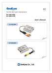
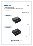
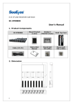
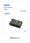
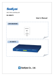
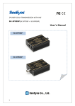
SC-UT/UR0115C Active UTP transmitter & receiver User’s Manual 1 Introduction 1.1 Overview The compact size SC-UT0115C and SC-UR0115C are active type UTP video transmission solutions with excellent interference immunity. As they are compatible with various applications, they can be linked with any type of camera and/or DVR. The UT0115C transmits video signals to long distance up to 1.5km in color without degradation. 1.2 Features • • • • • • • • • • Video transmission up to Max 1.5km (color) in high mode Active operation Excellent interference immunity Distance level switch (Low: under 600m, High: 600m~1.5km) Optimum video quality setting by the sync & burst adjustment (A.Level / F. Level) Possible to use the camera power adapter when connect the adapters in parallel (with power consumption under 30mA) Easy to install to the camera and/or the DVR Red LED indicator when operating Terminal block connector for easy installation Non polarity 1.3 Components Please find the below components in your package. SC-UT0115C and/or SC-UR0115C User’s Manual 2 Product Parts and Peripheral Device Connection 2.1 Part Names and Functions 2.1.1 SC-UT0115C (Transmitter) ② ③ ④ ① ⑤ ⑥ ① VIDEO IN: Connect to the video output of the camera (BNC-F) ② Distance Level: Adjust the distance level switch according to the cable distance. L (Low): under 600m / H (High): 600m ~1.5Km ③ POWER IN: Connect to the power adapter (non polarity) ④ POWER IN: Connect to the power adapter (non polarity) ⑤ VIDEO OUT (-): Connect the UTP cable to transmit the video. ⑥ VIDEO OUT (+): Connect the UTP cable to transmit the video. 2.1.2 SC-UR0115C(Receiver) ② ③ ① ⑦ ④ ⑧ ⑤ ⑥ ① VIDEO OUT: Connect to the Video input port (BNC-F) of the DVR or the Monitor. ② Distance Level: Adjust the distance level switch according to the cable distance. L (Low): under 600m / H (High): 600m ~1.5Km ③ POWER IN: Connect to the power adapter (non polarity) ④ POWER IN: Connect to the power adapter (non polarity) ⑤ VIDEO OUT (-): Connect the UTP cable to receive the video. ⑥ VIDEO OUT (+): Connect the UTP cable to receive the video. ⑦ A. Level: Adjust the brightness ⑧ F. Level: Adjust the color How to control the A/F Level: Please follow the order below to adjust the gain control of A/F level. 1. Adjust minutely the A. Level. 2. Then, adjust minutely the F. Level. 3. Adjust the A. Level and then the F. Level until you get the optimum video you want. Please note that if the A/F levels are in excessively high level, it may find cross-talk in the video depending on the DVR quality. In this case, please turn down the A/F level. 2.2 Peripheral Device Connection 2.2.1 Configuration Example 1- Standard type 2.2.2 Configuration Example 2 – Complex type 2.3 How to connect the UTP cable Please connect the UTP cable according to the below table. No. 1 2 3 4 5 6 7 8 Color Orange Orange + White Green Green + White Blue Blue + White Brown Brown + White Function VIDEO + VIDEO - POWER POWER POWER POWER + + - 3 Precautions 4 Make sure to turn the product off prior to installation. Do not install or use the device in a humid, hot or hazardous explosive environment. The operating temperature of this product is between -10℃ ~ +50℃. Do not expose the product to higher or lower temperatures. Do not expose the device to magnetic materials, high frequency radio waves. Avoid exposing the device to direct sunlight or into an unstable environment. Do not drop the product or subject it to shock. Do not modify or disassemble the product. When installing the product, make sure to wire the product and peripheral devices properly. Do not switch the lines. The installation should be made by a qualified service person and should conform to all local codes. Please note that the transmission distance may vary depending on the loop resistance and the signal diminution of the cable. If there is any malfunction in the device, please contact your distributor immediately. Specifications MODEL SC-UT0115C(Tx.) SC-UR0115C(Tx.) Video IN Video OUT Power Consumption CVBS 1.0Vp-p,75Ω 51Ω 1Vp-p ~ 2.5Vp-p Under 25mA Power for Camera (AC 24V / DC 12V) 1.5Km:6MHz Low: under 600m, High: 600~1.5Km 51Ω 1Vp-p ~ 2.5Vp-p CVBS 1.0Vp-p, 75Ω Under 25mA With Adapter: DC12V 500mA, AC24V300mA 1.5Km:6MHz Low: under 600m, High: 600~1.5Km VR(A. Level/F. Level) Selectable between H/L 4P Terminal Block (1,2: VIDEO / 3,4: POWER) Power INPUT Bandwidth Max. Distance (CAT. 5) Video Level Control Video IN Connect Port Video OUT Temperature / Humidity Case body / Weight Dimension (mm) BNC-M 4P Terminal Block (1,2: VIDEO / 3,4: POWER) -10℃ ~ +50℃ / 0 ~ 80% -10℃ ~ +50℃ / 0 ~ 80% ABS/ 20g 56(W) ⅹ 17(H) ⅹ 17(D) ABS/ 20g 56(W) ⅹ 17(H) ⅹ 17(D) BNC-M SeeEyes Co.,Ltd #502~506, Sunil Technopia, 440, Sangdaewon-Dong, Jungwon-Gu, Sungnam-Si, Gyeonggi-Do, Korea TEL : +82-(0)31-777-3508 FAX : +82-(0)31-777-3512 EMAIL : [email protected] http://www.sscctv.com/eng