1
2
Product Parts and Peripheral Device Connection
2.1 Part Names and Functions
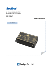
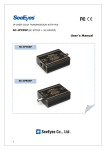
2.1.1 SC-UT0115C (Transmitter)
②
③
④
①
⑤
⑥
① VIDEO IN: Connect to the video output of the camera (BNC-F)
② Distance Level: Adjust the distance level switch according to the cable
distance.
L (Low): under 600m / H (High): 600m ~1.5Km
③ POWER IN: Connect to the power adapter (non polarity)
④ POWER IN: Connect to the power adapter (non polarity)
⑤ VIDEO OUT (-): Connect the UTP cable to transmit the video.
⑥ VIDEO OUT (+): Connect the UTP cable to transmit the video.
2.1.2 SC-UR0115C(Receiver)
②
③
①
⑦
④
⑧
⑤
⑥
① VIDEO OUT: Connect to the Video
input
port
(BNC-F) of the DVR or the Monitor.
② Distance Level: Adjust the distance level switch according to the cable
distance.
L (Low): under 600m / H (High): 600m ~1.5Km
③ POWER IN: Connect to the power adapter (non polarity)
④ POWER IN: Connect to the power adapter (non polarity)
⑤ VIDEO OUT (-): Connect the UTP cable to receive the video.
⑥ VIDEO OUT (+): Connect the UTP cable to receive the video.
⑦ A. Level: Adjust the brightness
⑧ F. Level: Adjust the color
How to control the A/F Level:
Please follow the order below to adjust the gain control of A/F level.
1. Adjust minutely the A. Level.
2. Then, adjust minutely the F. Level.
3. Adjust the A. Level and then the F. Level until you get the optimum
video you want.
Please note that if the A/F levels are in excessively high level, it may find
cross-talk in the video depending on the DVR quality. In this case, please
turn down the A/F level.