1
User Manual
SPCS-2 Servo Pneumatic Proportional Control System
Table of Contents
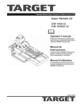
SPCS INTRODUCTION
3
SYSTEM SETUP - CONNECTION
4
SOFTWARE & FACTORY DEFAULT SETTINGS8
LOAD & VELOCITY CHARTS
10
TROUBLESHOOT
13
TECHNICAL DATA
14
AUTO COM PORT DETECTION
15
NOTICE & WARRANTY
19
SPCS Introduction
Introduction
The Servo Pneumatic Control System (SPCS) is a high flow pneumatic motion control valve that when
combined with a position feedback actuator provides a “closed loop” positioning control system that
quickly and accurately positions a payload.
System configuration and setup is completed by using a standard USB connection and Bimba’s SPCS
software. The valve is IP65 compatible and can be used with both linear and rodless actuators with either
an internal or external positioning transducer.
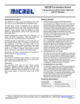
Software, System Connection and Setup
Flowchart outlining software download and establishing valve communications.
Download and install
SPCS USB Interface
from Bimba’s Website
(see section 1)
SPCS-2 FLOWCHART
Open SPCS Interface
(see section 2)
No
Did the Interface Open?
Reinstall the program
Open interface
Did the
interface open?
Contact Bimba Support
or your IT personnel
No
Yes
Yes
If this worked, go
back to COM port
selection
Select the COM port the
SPCS is connected to
Was the SPCS valve
available for selection
on the dropdown
menu?
No
Confirm power
is applied to the
valve
Is the valve now
selectable?
Yes
Confirm
MB cable
connection
Yes
Is the
valve now
selectable?
No
Go to the Drive
troubleshooting
(see section 3)
Yes
Enable connection
to valve
Does it
work now?
Yes
No
Contact Bimba
Support
You have successfully
installed the software/
driver!
2014.01.23 rev4
3
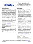
1. Connecting to Valve
“With the air supply and power turned off”
1. Connect the SPCS-2 to the Bimba position feedback cylinder using cable SPCS-CBL-FBK.
2. If required, remove the top from the SPCS and configure internal jumper as shown in the illustration
below.
3. Connect the SPCS-2 to your power and command sources using cable SPCS-CBL-PWR-CMD.
4. Connect Pneumatic Lines.
a. Connect port 2 of the SPCS-2 to the back of the cylinder and port 4 to the front.
(3/8” O.D. tubing – 10’ or less length is recommended to prevent performance loss)
b. Inlet air should be dry (-40° F dew point) non-lubricated air, non-flammable & non-corrosive dry
gases (0.3 micron fine grade coalescing filter with 5 micron pre-filter) at 0-150psig.
c. Connect Inlet air to Port 1.
Cable: SPCS-SBL-FBK
Cable: SPCS-CLB-PWR-CMD
Power/Command & Feedback Connectors
5. Connect the valve to your computer using USB cable SPCS2-USB-CBL.
6. Must use a coalescing filter.
2014.01.23 rev4
4
1. Connecting to Valve
a. Download the SPCS USB software found on Bimba’s
website:
www.bimba.com/products-and-cad/actuators/inch/position-control/
controllers11/servo-proportional-control-system/
c. Click the “Run” button.
2014.01.23 rev4
b. After the software package “Bimba SPCS Setup.zip” has
downloaded, double click on the highlighted file, (usually
the file can be found in the Download folder. Then click
open.
d. Click on the “I accept the terms in the License
Agreement”, then click on “Next >”.
5
1. Connecting to Valve
e. Click on the “Next >” button.
f. Click on the “Next >” button.
g. Click the “Install” button.
h. Click the “Finish” button.
2014.01.23 rev4
6
2. Opening SPCS USB Interface
e. Click on the Bimba SPCS button in the Start Menu,.
Initial Setup Screen
• Communication: Select the Select Port dropdown window: Select a Com Port and click the Enable
Communication check box. If communication is established the remaining screen selections will become available. You may have several Com ports from which to choose – you may have to repeat the
selection process above to find the correct one.
(All selections are “grayed out” until communication is established)
• Select Signals – Both command and feedback signals are selected by clicking the appropriate button
– 0 to 10V is the default value.
• Enter cylinder bore size and rod diameter using the up or down arrows. (Rodless cylinders: set rod
size at zero)
• Select Port Communication based upon your installation.
• After entry click
The initial setup parameters, as well as those on the Basic Setup and Advanced Setup screens described below can be saved and reloaded for further adjustments or to program another valve. Upon
clicking the “Save Configuration” button a window will appear that allows you to enter a file name and
save it.
Click this button to load previously saved programs. A window will appear asking you
to select and load a program.
Click this button to save a new program or a program loaded from an existing file to
the valve.
Note: Mouse over “Tool Tips” are provided for each selection.
2014.01.23 rev4
7
3. Basic Settings
Proportional, Derivative, Force Damping, Offset -- At setup the default settings are set at zero. After adjustment, if necessary they can be reset to the default value by clicking:
Analog Button: Selection allows operation using an external signal source.
PC Slider Button: Selection allows operation by moving the Cylinder Command slider up and down,
extending and retracting the cylinder.
PC Square Wave Button: Sends a square wave command signal based upon the gain perimeters described
below, the minimum/maximum rod positions, ramp up/ramp down and period settings found on the
Advance Setting screen. When selected the cylinder will operate using a square way generated by the
software. You can adjust the gain, rod position and period perimeters during operation to further
understand system responsiveness.
Gain Settings
Proportional
Increase or Decrease the cylinders responsiveness to changes in the command or feedback signal. Lower
% slower responsive – Higher % quicker response. Note: If too high system becomes unstable. Suggested
starting value 15% (Higher % needed for bore sizes 1-1/16” and below – Lower % needed for bore sizes
above 1-1/16”)
Derivative
Prevents Overshoot – Reduces overshoot and soothes system performance. Too high of a percentage gain
can cause undershoot and creep into the target position as well as system instability. Suggested starting
value 0.
Force Damping
Increase or Decrease Force Damping – Increases system stability. Lower % less force damping – Higher
% more force damping. Too little force damping can create an oscillating rod condition. Too much force
damping can result in a nonresponsive system. Suggested starting value 15%.
Offset
Offset - Offset is used when the cylinder is mounted vertically to create symmetrical or balanced motion. If
the cylinder is facing “rod up”, the offset should be increased. When a cylinder is facing down the offset
should be decreased (Negative setting). Value should be set to 0 for horizontal applications
Save your settings:
Oscillations: If the rod begins a rapid oscillation the Proportional or Force Damping % requires adjustment.
To correct this either decrease the Proporational gain or increase Force Damping
2014.01.23 rev4
8
3. Advance Settings
Determine the electrical offset % between the Cylinder command signal and the Cylinder feedback signal
• Minimum Position Slide: Move the slide to zero
• Maximum Position Slide: Move the slide to 100%
• Cylinder Command Slide: Move the slide to zero (the cylinder should fully retract) – note the percentage at the top of the Cylinder Feedback Slide. The percentage shown is the offset that should
be adjusted for in setting your command signal to retract the cylinder to a specific position.
• Repeat this process with the cylinder fully extended (Move the Cylinder Command to 100%) Note
the % difference between the Cylinder Command and the Cylinder Feedback percentages. Use this
to compensate for extending the cylinder to a specific position along the rod length.
(You may need to add the % offset to the required position when using rod positions other than fully extend
and retract)
Period – This sets the time it takes to complete a full cycle.
Minimum Position – Retract; Zero equals full retract; Higher % sets rod retract before full mechanical
retract – Ex. 5” rod, set at 35% - rod retract stopping point equals 1.75”. Prevents piston bottoming out at
full retract.
Maximum Position – Extend; 100% is fully extended. Lower % set maximum extend at less than
mechanical full extend – Ex. 5” rod, set at 85% - full rod extension 4.25”. Prevents piston striking the rod
guide at full extend.
Ramp Up – Increases or decreases extend speed. Higher % reduces speed; Lower % increases speed.
Ramp Down – Increases or decreases retract speed. Higher % reduces speed; Lower % increases speed.
When PC Square Wave is selected and the system is operating you can change the perimeters to further
adjust the valve and cylinder responsiveness.
2014.01.23 rev4
9
3. Linear & Rotary Cylinder Load Vs. Velocity
Maximum Moving Mass
The tables below recommend the maximum moving mass controlled by a SPCS-2 for horizontal and
vertical applications. Information for Bimba’s PFC, Pneu Turn and Ultran magnetically coupled cylinders is
included. Actual mass will vary based on cylinder speed and mechanical assembly
(e.g. friction in cylinder or system, air pressure, etc.)
Linear Cylinder
Horizontal Applications
Bore Size
Average Velocity
Without Overshoot @
Max Payload [in/sec]
Maximum Payload
[lbs.]
Average Velocity @ 50%
Max Payload
[in/sec]
Average Velocity @ 25%
Max Payload [in/sec]
09
20
50
20
30
17
10
100
20
30
31
15
200
20
30
50
15
315
25
30
70
15
450
20
20
Linear Cylinder
Vertical Applications
Bore Size
Average Velocity
Without Overshoot @
Max Payload [in/sec]
Maximum Payload
[lbs.]
Average Velocity @ 50%
Max Payload
[in/sec]
Average Velocity @ 25%
Max Payload [in/sec]
09
70
5
100
100
17
70
10
60
60
31
50
30
40
60
50
15
95
30
30
70
20
135
20
20
Rotary Actuator
Rack and Pinion - Single Rack
Bore Size
Rotation
Average Velocity
Max Torque
1-1/2”
0 to 360°
150° per second
30 in/lb.
2”
0 to 360°
150° per second
84 in/lb.
Rack and Pinion - Double Rack
Bore Size
Rotation
Average Velocity
Max Torque
1-1/2”
0 to 360°
150° per second
60 in/lb.
2”
0 to 360°
150° per second
144 in/lb.
2014.01.23 rev4
10
3. Rodless Cylinder Load Vs. Velocity
Rodless Cylinder
Horizontal Applications
Bore Size
Average Velocity Without Overshoot
@ Maximum Payload
[in/sec]
Maximum Payload
[lbs.]
Average Velocity @
50% Maximum
Payload
[in/sec]
Average Velocity @ 25%
Maximum Payload
[in/sec]
USS-09X-L
6
84
16
27
UGS-09X-L
10
104
20
36
USS-17X-L
8
260
22
27
UGS-17X-L
7
260
21
30
Rodless
Vertical Applications
Bore Size
Average Velocity Without Overshoot
@ Maximum Payload
[in/sec]
Maximum Payload
[lbs.]
Average Velocity @
50% Maximum
Payload
[in/sec]
Average Velocity @ 25%
Maximum Payload
[in/sec]
USS-09X-L
24
12
26
28
UGS-09X-L
13
24
25
30
USS-17X-L
9
60
10
13
UGS-17X-L
10
48
17
22
2014.01.23 rev4
11
3. Cylinder Performance Graphs
2014.01.23 rev4
12
3. Troubleshooting Chart
Symptom
Probable Causes
Corrective Action
System Totally Unresponsive
Power not Applied
Apply power, check all power wiring
Air Off
Turn air on
Proportional Gain too Low
Basic Settings – Increase Proportional
Gain
Inverted Sensor Polarity
Initial Setup – Click the “Invert Feedback
Sensor Polarity” checkbox
Pneumatic Connections to Cylinder are
Backwards
Initial Setup – Click the “Transposed”
button under Port Connection
Proportional Gain too Low
Basic Settings – Increase Proportional
Gain
Force Damping Gain too High
Basic Settings - Decrease Force Damping
Power Supply Voltage not Stable
Check power wiring; change power supply
Cylinder too Small
Decrease moving mass, increase cylinder
size, or increase inlet pressure.
No Feedback Signal
Connect Feedback Signal
Feedback Connected Improperly
Verify all wiring is as shown in application
examples and as described in the “System
Setup” section of this document
Cylinder Connected Improperly
Verify airline connections
Incorrect Wiring
Verify all wiring is as shown in the System
Setup section of this document
Mechanical System
Insure mechanical system is free from
binding and high friction.
Proportional Gain too Low
Basic Settings – Increase Proportional
Gain
Force Damping Gain too high
Basic Settings - Decrease Force Damping
Offset Gain Adjusted incorrectly
Basic Settings - Adjust Offset
Incorrect Cylidner Bore or Rod Diameter
Entered
Initial Setup - Check Cylidner Bore and
Rod Size
Air Leaks
Insure there are no air leaks in the system
SPCS-2 Sticking
Insure that inlet air meets valve specifications. See “System Setup” – Contact
Bimba
Force Damping too Low
Basic Settings - Increase Force Damping
Proportional Gain too High
Basic Settings - Decrease Proportional
Gain
System Overshoots
Proportional Gain too High
Basic Settings - Decrease Prportional Gain
System ‘Buzzes’
Input Signal Noise (possibly 60Hz)
Verify that large or high power machinery
is not operating nearby. Also, verify input
signal integrity by examining the signal
with an oscilloscope.
Input Signals not connected
Verify all wiring as shown in the “System
Setup” section of this document
DC Common not connected
Verify all DC common connections
System Mildly Responsive or Sluggish
System Freezes Fully Extended or
Retracted
System Fails to Operate or is Inaccurate
System Oscillates
2014.01.23 rev4
13
3. Technical Data
Mechanical Specifications
Pressure: 0 – 150 psig (0 – 10 bar) Un-lubricated, Dry, Neutral Gas
Ports: 1/4” NPT
Connector: 4-pin M8 x 1 (male) and 3-pin M8 x1 (male)
Mounting: 2 x 10-32 thru Holes
Temperature Range: 32°F- 104°F (0°C - 40°C)
Filtration: 5 µm particulate
0.3µm coalescing
Weight: 2.0Lbs. (0.91 kg)
Body: Aluminum 6061
Performance
Position Accuracy: +- 1% of full stroke
Repeatability: 3mV
Flow: 46 SCFM @ 80 psig (820 SLPM @ 6 bar)
Leak Rate: 12 SCFH @ 150 psig (5.7 SLPM @ 10 bar)
Electrical Specifications
Power: 24 VDC nominal @ 20W
Command Input Impedance: 100kΩ
Feedback Input Impedance: 100kΩ
Command Input: Configurable 0…10 VDC; 4…20mA
Feedback Input: Configurable 0…10 VDC; 4…20mA
Excitation: +10V (15mA max)
2014.01.23 rev4
14
4. Appendix - Auto Com Port Detection
Step 1: How to Install/Detect the SPCS Communication Drives
a. Click the Start Menu.
b. Then click “Control Panel”.
c. Double Click on the “Device Manager”.
d. This will open the Device Manager Window. (The SPCS
drivers are located under Ports (COM & LPT) or Universal
Serial Bus controllers.
e. To detect any issues, look for devices in the Device
Manager that have an icon similar to the following (USB
with yellow exclamation mark signifying that the driver
is not recogonized). If no issues are detected, please
continue to Step 2.
f. Once the faulity driver has been identified, right click on
the driver (shown in blue) then left click on “Properties”.
2014.01.23 rev4
15
4. Appendix - Auto Com Port Detection
g. Next, select on the Driver tab (the following image is for
example purposes only, your driver properties menu may
appear differently).
h. Click on “Update Driver”.
i. A new window will open. Click “Search automatically
for updated driver software” (to enable to search online
{where the drivers are typically found}, establish an
interent connection prior to searching).
j. After the process is complete, the device under the Ports
section on the Device Manager window should be visible
and free of errors. If not, continue onto Step 2. In this
case, Port 7 is the connection to the SPCS.
2014.01.23 rev4
16
4. Appendix - Auto Com Port Detection
Step 2: How to Install/Detect the SPCS Communication Drives (continued)
a. Click the Start Menu.
b. Click on “Computer”.
c. Double click on the hard drive icon (usually C: or D:).
d. Double click on “Program Files (x86).
e. Double click on the “Bimba Folder”.
f. Double click on the “SPCS Folder”.
g. Double click on the “Driver Folder”.
h. Double click on the “CDM20828_Setup” application.
2014.01.23 rev4
17
4. Appendix - Auto Com Port Detection
i. Extract the files by clicking on the “Extract” button.
j. Click the “Next >” button.
k. Click “Finish” as the driver has now successfully installed
itself.
Go back to section 2: Opening SPCS Interface and restart the process of finding the COM Port.
If you still cannot locate the communicate the COM port, please contact the Bimba Manufacturing support
team.
2014.01.23 rev4
18
Notice & Warranty
Preface
Data, Illustrations, Alterations
Data and Illustrations are not binding. Bimba reserves the right to alter products in line with our policy of
continuous product development.
Use and purchase of this product is subject to Bimba Mfg. Terms and Conditions of Sale and Use.
Improper installation or use voids warranty. Consult factory regarding special applications. Specifications
are subject to change. Reasonable efforts have been made to provide useful and correct information in
this document, but this document may contain errors and omissions, and is subject to change.
Contact: Bimba Manufacturing Customer Support 800-44-Bimba or [email protected] or your local Bimba
Distributor for additional information.
Microsoft are registered trademarks of Microsoft Corporation; Windows is a brand name of the Microsoft
Corporation in the USA and other countries.
Bimba is a registered trademark of Bimba Manufacturing Company.
Copyright
All rights are rserved. No part of this document may be reproduced or transmitted in any form or by any
means, electronic or mechanical, including copying, processing or online file transfer, without permission
in writing by Bimba Manufacturing Company. You are not authorized to translate this document into any
other language.
2014 Bimba Manufacturing Company. All rights reserved.
WARNING:
Installation and operation of electric and high pressure systems (fluids and compressed gas) involves risk
including property damage and personal injury or death.
Installers and users should be properly trained or certified and take safety precautions. This product may
cause death, personal injury, or property damage if improperly used or installed.
The information in this document and other information from Bimba Mfg. and its authorized representatives
are intended for use by persons having technical expertise in selecting and using these products. Product
owners (“you”) should analyze all technical and safety requirements of your specific application, including
the consequences of any possible failure, before selecting a product. This product may not be suitable
for all applications, such as those acting upon people. Suitability is solely your responsibility. Because the
requirements for each application may vary considerably, you are solely responsible for conducting any
testing or analysis that may be required to determine the suitability of the product for your application, and
to ensure that all performance, safety and warning requirements for your application are met.
While this product is low voltage, it contains open-frame electronic components and care should be taken
to prevent un-intentional contact with the productt to avoid damage to the person or property.
Warranty:
This product is covered by a one year Bimba Mfg. limited warranty. Use without a coalescing filter voids the
warranty. Contact Bimba Mfg. or visit website for more details.
2014.01.23 rev4
19