1
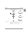
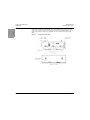
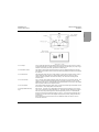
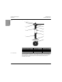
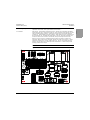
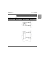
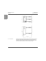
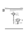
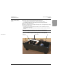
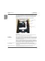
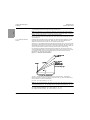
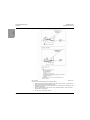
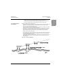
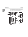
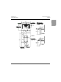
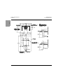
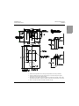
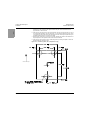
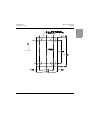
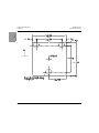
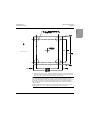
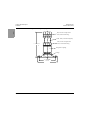
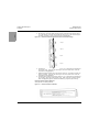
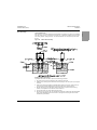
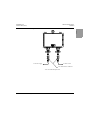
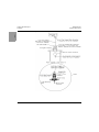
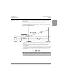
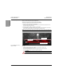
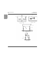
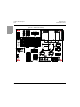
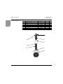
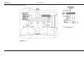
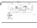
Introduction
L-880 & L-881 PAPI, Style A
Introduction
96A0209 Rev. AA
Document Date (7/2014)
2.2.5.2 Daytime Operation
When the illumination on the photocell rises to 50 to 60 foot-candles, the photocell PC1 is deenergized. This de-energizes relay K2 and provides 120 Vac to J2-7 on LC-control PCB1
and turns on the PAPI system to full intensity.
2.2.5.3 Nighttime Operation
When the illumination drops to 25 to 35 foot-candles, photocell PC1 energizes. This
energizes relay K2 and removes 120 Vac from J2-7 on LC-control PCB1. This causes the
PAPI system to operate at low intensity (if the interlock relay is used, the PAPI system will not
energize until the interlock relay CS1 detects the current flow). A time delay of 45-75
seconds is incorporated in the photocell circuit to prevent switching because of stray light or
temporary shadows. In case of failure of the photocell control circuitry, the system reverts to
high intensity. Two night intensity settings, approximately 5% and 20% of full intensity, can
be set by using toggle switch S2. This allows the user to select either of the two settings to
accommodate local site conditions.
NOTE: Refer to “Optional Interlock Relay” on page 12.
2.2.5.4 Remote/Local Operation
Toggle switch S1 allows the unit to operate either in REM or LOCAL. When the switch is set
to LOCAL, the unit can be operated locally. When the switch is set to REM and the remote
wires are connected to TB1-7 and TB1-8, the unit can be operated from a remote location by
a switch closure across TB1-7 and TB1-8.
2.2.5.5 Light Unit
See Figure 6 and Figure 7. Power is provided to the lamps in the light boxes via TB1-13 and
TB1-14 in the master and are connected in series. The normally closed tilt switch in each unit
is connected to TB1-5 and TB1-6 and are connected in series. These wires connect to TB19 and TB1-10 in the master unit. If the optional heater is used in the tilt switch, two wires
must be connected from TB1-11 and TB1-12 on the master unit to TB1-7 and TB1-8 on all the
light units to provide power to the heater when required.
2.2.5.6 Optional Heater
See Figure 9. Thermostat TH1 in the master is used to supply 240 Vac to the heater. When
the outside air temperature drops below 0 °F, the thermostat turns on. This provides 240 Vac
to the heater resistors R1 in the tilt switch boxes. This prevents the mercury in the tilt
switches from freezing.
2.2.5.7 Optional Interlock Relay
This option provides ON/OFF control through current sensing of the runway series circuit
during nighttime operations.
2.2.5.8 Tilt Switch
The tilt switch assembly is designed to de-energize the lamps if the optical pattern is raised
more than 1/2 degree or lowered more than 1/4 degree with respect to the present setting
angle of the light unit. If a tilt switch is moved from proper alignment, the time delay relay in
the master will de-energize after a nominal 15-second time delay, which de-energizes the
system and removes the 6.6 A power supply to all the lamps in the PAPI system.
12
© 2014 ADB Airfield Solutions All Rights Reserved