1
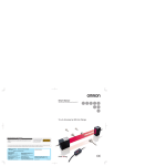
Access DCS-MUX Loop-AM3440 Access DCS-MUX Description Features : Support DACS (Digital Access Cross-connect System) with full cross-connect Support full DS0 cross-connect, backplane capacity up to 128 Mbps Single controller, dual controller (1+1 protection) option Support 1 for 1 protection Y-BOX (Optional) Up to 64E1 or 64T1 WAN ports, or 4 E1/ T1 ATM Frame Relay Single –48V DC or optional dual –48V DC with load sharing 12 DTE plug-in slots Mini plug-in card types: − − − − − − E1 card T1 card Mini Quad E1 E1/T1 ATM/Frame Relay card 10/100baseT Router card Fiber optical card − − − − − − − − − − − − − − − − 4-channel E1/ T1 card 6-channel U card 10-channel U card 3-channel MDSL card without line power 2-channel G.SHDSL card (2 pair) w/o line power 4-channel G.SHDSL card (1 pair) w/o line power 8-channel G.703 card at 64 Kbps data rate 8-channel Dry Contact I/O card 8-channel 2W/4W E&M card 12-channel FXS card 12-channel FXO card 12-channel Magneto card 8-channel OCU-DP card 1-channel low speed optical (C37.94) card 4-channel low speed optical (C37.94) card 8-channel RS232 with X.50 subrate card − − − − − − − − − − − 3-channel MDSL card with line power 6-channel X.21 card 6-channel V.35 card 6-channel V.36 card 6-channel EIA530 card 5-channel RS232 with X.50 subrate card 24-channel FXS card 24-channel FXO card 24-channel Magneto card 2-channel G. SHDSL card (2 pair) with line power 4-channel G. SHDSL card (1 pair) with line power Single-slot plug-in card types: Dual-slot plug-in card types: The Loop-AM3440 is an access DCS-MUX that can combine various digital access interfaces into E1 or T1 lines for convenient transport and switching. The Loop-AM3440 Access DCS-MUX provides access for a variety of interfaces, including mini Quad E1, Quad E1/T1, ATM/ FR, 10/100baseT Router, FOM, MDSL, G.SHDSL, G.703, U type, X.21, V.35/V36, RS232, E&M, FXS, FXO and Magneto. These interfaces are compatible with other Loop products such as the Loop-H 3900 (MDSL) and the Loop-U 3500 (U). Using these products, a DTE interface can be extended over RS232 copper wire pairs. Up to 120 time slots for the MDSL, U, RS232, X.21, V.36 and V.35 interfaces are then multiplexed to fill an E1 or T1 line, with full flexibility of time slot interchange. AM3440 also support fiber optical plug-in module, which can be used to aggregate up to 4 E1 channels to single fiber optical interface to connect with other AM3440 or O9310. This unit is a full cross-connect and can act as a mini DACS. This means that one or more of the WAN ports can be used as a Drop & Insert function with fractional E1/T1 lines, which can be muxed into a full E1/T1 line. Redundancy is available in dual CPU controller and power supply options, making it an excellent fit for critical applications. And, though the chassis does not contain and has no need for fan cooling, a fan tray is available. The Loop-AM3440 supports local control and diagnostics by using an external 2-line by 40-character LCD display and keypads, or by using a VT-100 terminal connected to the console port. The Loop-AM3440 also supports Ethernet, SLIP, Telnet, and SNMP, so that it can be controlled and diagnosed from remote locations as well. An in-band management channel with GUI are available. In addition to the LCD display, there is LED indication for all plug-in cards. Finally, the Loop-AM3440 consists of a rugged chassis made from reinforced aluminum, giving this equipment a more durable structure and a longer physical life. Telnet, SLIP, SNMP, and Inband management support Craft interface port for connection to external LCD display Compatible to a GUI network management system Ordering Information To specify options, choose from list below: Note: RoHS compliant units are identified by the letter G appearing immediately at the end of ordering code. Model Description Note Main Unit Loop-AM3440-CHA Loop-AM3440-CHA-G Wideband Main Unit without CPU, power, E1/T1 card Basic Chassis CPU Module Loop-AM3440-CCA-T Loop-AM3440-CCA-T-G CPU card for 128Mbits back plane capacity, with T1 External Clock (order two for redundancy) Loop-AM3440-CCA-E Loop-AM3440-CCA-E-G CPU card for 128Mbits back plane capacity, with E1 External Clock(order two for redundancy) For Loop-AM3440-CHA only. Mini Plug-in Module (Select 1 to 4 cards from below list.) Loop-AM3440-E1 Loop-AM3440-E1-G E1 Interface Loop-AM3440-T1 Loop-AM3440-T1-G T1 Interface Loop-AM3440-M4E75 Loop-AM3440-M4E75-G Mini Quad E1 Interface w/ 75 ohm Loop-AM3440-M4E120 Loop-AM3440-M4E120-G Mini Quad E1 Interface w/ 120 ohm Loop-AM3440-AFRE Loop-AM3440-AFRE-G E1 Frame Relay to ATM inter-working or Frame Relay to Frame Relay concentration Loop-AM3440-AFRT Loop-AM3440-AFRT-G T1 Frame Relay to ATM inter-working or Frame Relay to Frame Relay concentration Loop-AM3440-RT Loop-AM3440-RT-G Router / Bridge Card Loop-AM3440-RTA Loop-AM3440-RTA-G 64 WAN ports router/bridge card Loop-AM3440-FOM-OPT Loop-AM3440-FOM-OPT-G Fiber Optical Interface For Loop-AM3440-CHA with Loop-AM3440-CCA CPU only. Include a 1M 8-BNC to DB25 Conversion Cable Include a 1M 4-Phone Jack to DB25 Conversion Cable Single Slot Plug-in Module (Shares the 12 available slots with the single slot cards.) Loop-AM3440-4E1-cc Loop-AM3440-4E1-cc-G Loop-AM3440-4T1 Loop-AM3440-4T1-G 4-channel E1 Interface where cc = RJ for RJ48C connector BNC for BNC connector For Loop-AM3440-CHA with Loop-AM3440-CCA CPU only. 4-channel T1 Interface Loop-AM3440-6U Loop-AM3440-6U-G 6-channel IDSL plug-in module Loop-AM3440-10U Loop-AM3440-10U-G 10-channel IDSL plug-in module Loop-AM3440-3HA Loop-AM3440-3HA-G 3-channel 6Mbits MDSL plug-in module (2Mbits per channel) Loop-AM3440-2GH Loop-AM3440-2GH-G 2-channel G.SHDSL plug-in module (2 pair) For Loop-AM3440-CHA with Loop-AM3440-CCA CPU only. With line power, takes 2 DTE slots per card. For Loop-AM3440-CHA with Loop-AM3440-CCA CPU only. Loop-AM3440-4GH Loop-AM3440-4GH-G 4-channel G.SHDSL plug-in module (1 pair) For Loop-AM3440-CHA with Loop-AM3440-CCA CPU only. Loop-AM3440-8CD Loop-AM3440-8CD-G 8-channel G.703 Interface at 64 Kbps data rate For Loop-AM3440-CHA with Loop-AM3440-CCA CPU only. Loop-AM3440-8DC Loop-AM3440-8DC-G 8-channel dry contact I/O plug-in module For Loop-AM3440-CHA with Loop-AM3440-CCA CPU only. Loop-AM3440-8EM-x Loop-AM3440-8EM-x-G 8-channel 2W/4W E&M plug-in module Loop-AM3440-12FXS Loop-AM3440-12FXS-G 12-channel FXS plug-in module with 600/ 900 Impedance, Battery Reverse, PLAR, without Ground Start and Metering Pulse Loop-AM3440-12FXS-P Loop-AM3440-12FXS-P-G 12-channel FXS plug-in module with 600/ 900 Impedance, Battery Reverse, PLAR, PLAR bit programmable function , without Ground Start and Metering Pulse Loop-AM3440-12FXS-M Loop-AM3440-12FXS-M-G 12-channel FXS plug-in module with 600/ 900 Impedance, Battery Reverse, PLAR, [Metering Pulse] Loop-AM3440-12FXS-MP Loop-AM3440-12FXS-MP-G 12FXS-GM includes all function of FXS Cards, except 12FXS-P and 12FXS-GMP. 12-channel FXS plug-in module with 600/ 900 Impedance, For Loop-AM3440-CHA with Battery Reverse, PLAR and PLAR bit programmable function, Loop-AM3440-CCA CPU only. [Metering Pulse] Loop-AM3440-12FXS-GS Loop-AM3440-12FXS-GS-G 12-channel FXS plug-in module with 600/ 900 Impedance, Battery Reverse, PLAR, [Ground Start] Loop-AM3440-12FXS-GM Loop-AM3440-12FXS-GM-G 12-channel FXS plug-in module with 600/ 900 Impedance, Battery Reverse, PLAR, [Ground Start, and Metering Pulse] 12-channel FXS plug-in module with 600/ 900 Impedance, Loop-AM3440-12FXS-GMP Battery Reverse, PLAR and PLAR bit programmable function, Loop-AM3440-12FXS-GMP-G [Ground Start, and Metering Pulse] Loop-AM3440-12FXO Loop-AM3440-12FXO-G 12-channel FXO plug-in module with 600/ 900 Impedance, Battery Reverse, without Ground Start and Metering Pulse Loop-AM3440-12FXO-M Loop-AM3440-12FXO-M-G 12-channel FXO plug-in module with 600/ 900 Impedance, Battery Reverse, [ Metering Pulse ] Loop-AM3440-12FXO-GS Loop-AM3440-12FXO-GS-G 12-channel FXO plug-in module with 600/ 900 Impedance, Battery Reverse, [ Ground Start ] Loop-AM3440-12FXO-GM Loop-AM3440-12FXO-GM-G 12-channel FXO plug-in module with 600/ 900 Impedance, Battery Reverse, [ Ground Start, and Metering Pulse ] Loop-AM3440-12MAG-1G Loop-AM3440-12MAG-1G-G 12-channel Magneto plug-in module with L1. GND Loop-AM3440-12MAG-12 Loop-AM3440-12MAG-12-G 12-channel Magneto plug-in module with L1, L2 12FXO-GM includes all function of FXO Cards. For Loop-AM3440-CHA with Loop-AM3440-CCA CPU only. 12MAG-1G2 includes all function of MAG Cards. Loop-AM3440-12MAG-1G2 12-channel Magneto plug-in module with L1, L2, and L1. GND Loop-AM3440-12MAG-1G2-G Loop-AM3440-1C37 Loop-AM3440-1C37-G 1- channel C37.94 plug-in module Loop-AM3440-4C37 Loop-AM3440-4C37-G 4- channel C37.94 plug-in module Loop-AM3440-ODP 8-channel OCU-DP plug-in module Loop-AM3440-8RS232 Loop-AM3440-8RS232-G 8-channel RS232 plug-in module with X.50 Subrate (RJ48 Connector) For Loop-AM3440-CHA with Loop-AM3440-CCA CPU only. Dual Slot Plug-in Module (Shares the 6 available slots with the dual slot cards.) Loop-AM3440-6X21A Loop-AM3440-6X21A-G 6-channel X.21 card with DB15 connector For Loop-AM3440-CHA with Loop-AM3440-CCA CPU only. Loop-AM3440-6V35A Loop-AM3440-6V35A-G 6-channel V.35 plug-in modules with DB25S connector, for M34 please order conversion cable connector below. (2Mbits per channel) For Loop-AM3440-CHA with Loop-AM3440-CCA CPU only. Loop-AM3440-6V36A Loop-AM3440-6V36A-G 6-channel V.36 card with DB25 connector via conversion cable to DB37 Loop-AM3440-6E530A Loop-AM3440-6E530A-G 6-channel EIA530 card with DB25 connector Loop-AM3440-6RS449A Loop-AM3440-6RS449A-G 6-channel EIA530 card with DB25 connector via conversion cable Loop-AM3440-5RS232 Loop-AM3440-5RS232-G 5-channel RS232 with X.50 subrate plug-in module Loop-AM3440-24FXS Loop-AM3440-24FXS-G 24-channel FXS plug-in module with /600/ 900 Impedance, Battery Reverse, PLAR, without Ground Start and Metering Pulse Loop-AM3440-24FXS-P Loop-AM3440-24FXS-P-G 24-channel FXS plug-in module with 600/ 900 Impedance, Battery Reverse, PLAR, PLAR bit programmable function , without Ground Start and Metering Pulse Loop-AM3440-24FXS-M Loop-AM3440-24FXS-M-G 24-channel FXS plug-in module with 600/ 900 Impedance, Battery Reverse, PLAR, [Metering Pulse] Loop-AM3440-24FXS-GS Loop-AM3440-24FXS-GS-G 24-channel FXS plug-in module with 600/ 900 Impedance, Battery Reverse, PLAR, [Ground Start] Loop-AM3440-24FXS-GM Loop-AM3440-24FXS-GM-G 24-channel FXS plug-in module with 600/ 900 Impedance, Battery Reverse, PLAR, [Ground Start, and Metering Pulse] 24FXS-GM includes all function of FXS Cards, except 24FXS-P and 24FXS-GMP. 24-channel FXS plug-in module with 600/ 900 Impedance, Loop-AM3440-24FXS-GMP Battery Reverse, PLAR and PLAR bit programmable function, Loop-AM3440-24FXS-GMP-G [Ground Start, and Metering Pulse] Loop-AM3440-24FXO Loop-AM3440-24FXO-G 24-channel FXO plug-in module with 600/ 900 Impedance, Battery Reverse, without Ground Start and Metering Pulse Loop-AM3440-24FXO-M Loop-AM3440-24FXO-M-G 24-channel FXO plug-in module with 600/ 900 Impedance, Battery Reverse, [Metering Pulse] Loop-AM3440-24FXO-GS Loop-AM3440-24FXO-GS-G 24-channel FXO plug-in module with 600/ 900 Impedance, Battery Reverse, [Ground Start] Loop-AM3440-24FXO-GM Loop-AM3440-24FXO-GM-G 24-channel FXO plug-in module with 600/ 900 Impedance, Battery Reverse, [Ground Start, and Metering Pulse] Loop-AM3440-24MAG-1G Loop-AM3440-24MAG-1G-G 24-channel Magneto plug-in module with L1. GND Loop-AM3440-24MAG-12 Loop-AM3440-24MAG-12-G 24-channel Magneto plug-in module with L1, L2 Loop-AM3440-3HAL 3-channel 6Mbits MDSL plug-in module with line power source 24FXO-GM includes all function of FXO Cards. Future option Factory installed option available with -48 Vdc powered chassis only. Fan tray required. Loop-AM3440-2GHL Loop-AM3440-4GHL 2-channel G.SHDSL plug-in module with line power source (140 VDC, 110mA), (2 pair) 4-channel G.SHDSL plug-in module with line power source (190 VDC, 60mA), (1 pair) For Loop-AM3440-CHA with Loop-AM3440-CCA CPU only. With line power, takes 2 DTE slots per card. For Loop-AM3440-CHA with Loop-AM3440-CCA CPU only. With line power, takes 2 DTE slots per card. Accessories User’s Manual Loop-AM3440-UM User’s Manual (paper, hard copy-optional). A CD version of the manual is already included as standard equipment. Power Module Loop-AM3440-SD Loop-AM3440-SD-G Single –48V DC Power Module (100W UM5813) Order 2 single DC for dual DC application. Loop-AM3440-S5 Loop-AM3440-S5-G Single –48V DC Power Module (150W UM5613) Order 2 single DC for dual DC application. Future option Adaptor Loop-AM3440-APA-150 Loop-AM3440-APA-150-G AC (100-240 Vac) to DC (48 Vdc = 3.3A) adaptor for USA Loop-AM3440-APE-150 Loop-AM3440-APE-150-G AC (100-240 Vac) to DC (48 Vdc = 3.3A) adaptor for Europe Loop-AM3440-APU-150 Loop-AM3440-APU-150-G AC (100-240 Vac) to DC (48 Vdc = 3.3A) adaptor for UK Fan Tray Loop-AM3440-FAN Loop-AM3440-FAN-G Fan tray Power supplied from rear of chassis. External LCD monitor Optional E1 ring software (future option) Optional (Only available for CHA, CCA, and 4E1) External LCD Monitor Loop-AM3440-LCD Loop-AM3440-LCD-G Software Loop-AM3440-ERING Conversion Cable Loop-ACC-CAB-DTE-001 Loop-ACC-CAB-DTE-001-G V.35 DB25 to M34 conversion cable L: 30cm Y-Box Loop-VV-B Loop-VV-B-G 1 for 1 protection Y-Box with BNC connectors (4-E1) Loop-VV-R Loop-VV-R-G 1 for 1 protection Y-Box with RJ48C connectors (16-E1) Loop-VV-T Loop-VV-T-G 1 for 1 protection Y-Box with RJ48C connectors (16-T1) Tapping Bridge Loop-ACC-TB T1/E1 Tapping Bridge (T1/E1) Blank Panels 30.000333.A00 30.000333.A00-G Blank Panel for Power Supply Slot (flat) 30.000349.A00 30.000349.A00-G Blank Panel for Controller Slot (flat) 30.000335.A00 30.000335.A00-G Blank Panel for Slot A-D (flat) 30.000331.A00 30.000331.A00-G Blank Panel for Slot 1-12 (flat) 30.001028.A00 30.001028.A00-G Blank Panel for Power Slot (u-shape) 30.001029.A00 30.001029.A00-G Blank Panel for Controller (u-shape) 30.001030.A00 30.001030.A00-G Blank Panel for Slot A-D (u-shape) 30.001027.A00 30.001027.A00-G Blank Panel for Slot 1-12 (u-shape) NOTE: When all these plug-in modules, two CPU cards, four mini Quad E1 cards, ten G.shdsl cards, and one 100W UM5813 power module, are plugged into an AM3440, one more 100W UM5813 power module should be ordered to the AM3440. For Example: Loop-AM3440-CHA, Loop-AM3440-CCA, Loop-AM3440-4E1, Loop-AM3440-10U, Loop-AM3440-SD: For model 3440 wideband controller with CPU card for 128Mbits backplane capacity, 4-channel E1 interface, one 10-port IDSL plug-in module, and one single DC power. where OPT is used to select optical module type: OPT = Description single optical module with dual uni-directional fiber, 1310 nm, SAA SC optical connector, 30 km reach (20dB) - S1.1 physical layer* single optical module with dual uni-directional fiber, 1310 nm, SBB SC optical connector, 50 km reach (30dB) - L1.1 physical layer* single optical module with dual uni-directional fiber, 1310 nm, SCC FC optical connector, 30 km reach (20dB) - S1.1 physical layer* single optical module with dual uni-directional fiber, 1550 nm, SDD SC optical connector, 20 km reach (12dB) - S1.2 physical layer* single optical module with dual uni-directional fiber, 1550 nm, SEE SC optical connector, 100 km reach (40dB) - L1.2 physical layer* SSM single optical module with single bi-directional fiber (master), 1310 nm transmit and 1550 receive, SC optical connector, 30 km reach (20dB) - S1.1/ S1.2 physical layer* SSS single optical module with single bi-directional fiber (slave), 1310 nm receive and 1550 transmit, SC optical connector, 30 km reach (20dB) - S1.1/ S1.2 physical layer* Note Use 2 fibers Units delivered ITU-T Rec G.957 application code 1310 nm from master to slave Order SSM to use with SSS Use 1 fiber TU-T Rec G.957 application code 1550 nm from slave to master Order SSS to use with SSM Use 1 fiber ITU-T Rec G.957 application code For other optical modules: MMSnn nn = 01 to 99 (contact sales for details) Other special optical modules for special order where x is used to select ABCD signaling bits type: x= Description Note E follows ETSI signaling bits A follows ANSI signaling bits R reverse for ON-HOOK and OFF-HOOK signaling bits exchange S follows customer’s special bit or function assignment T trunk condition = OFF-HOOK mode when alarm occur AR follows ANSI signaling bits and reverse bit AT follows ANSI signaling bits w/ trunk condition = OFF-HOOK mode RT reverse bits w/ trunk condition = OFF-HOOK mode ART selectable together to all channel follows ANSI signaling bits and reverse bits, w/ trunk condition = OFF-HOOK mode LOOP-AM3440 E1/T1 MUX Product Specifications Network Line Interface - T1 Line Rate 1.544 Mbps ± 50 bps Line Code AMI or B8ZS Input Signal ABAM cable length up to 655 feet Network Line Interface - E1 Line Rate 2.048 Mbps ± 50 ppm Line Code AMI or HDB3 Input Signal ITU G.703 to -10dB Output Signal ITU G.703 Network Line Interface - Mini 4E1 Line Rate 2.048 Mbps ± 50 ppm Line Code AMI or HDB3 Input Signal ITU G.703 to -10dB Output Signal ITU G.703 Network Line Interface - 4T1 Line Rate 1.544 Mbps ± 50 bps Line Code AMI or B8ZS Input Signal ABAM cable length up to 655 feet Network Line Interface - 4E1 Output Signal Framing Connector DSX1 D4/ESF (selectable) RJ48C Framing Connector Electrical Jitter ITU G.704 BNC/RJ48C 75 ohm Coax/120 ohm twisted pair ITU G.823 Framing Connector Electrical Jitter ITU G.704 DB25S 75 ohm Coax/120 ohm twisted pair ITU G.823 Output Signal Framing Connector DSX1 D4/ESF (selectable) RJ48C Line Rate Line Code Input Signal Output Signal 2.048 Mbps ± 50 ppm AMI or HDB3 ITU G.703 to -10dB ITU G.703 Framing Connector Electrical Jitter ITU G.704 BNC, RJ48C 75 ohm Coax/120 ohm twisted pair ITU G.823 ATM Frame Relay Network Line Interface Supporting Network Interworking (FRF.5) and service interworking (FRF.8). Network Interface: T1 ATM UNI − T1 Module: FR (n x 64 Kbps, n=1 to 31) E1 ATM UNI − E1 Module: FR (n x 64 Kbps, n= 1 to 31) Up to 31 logical FR channels can be concentrated/ de-concentrated to FR or ATM. Service Ports: n x 64 Kbps, n=1 to 24 − T1/FT1 interface: n x 64 Kbps, n= 1 to 31 − E1/FE1 interface: Support HDLC to FR Support HDLC to ATM Supporting FR to FR multiplexing. Support up to 128 DLCIs for total of 31 FR interfaces. Support up to 128 VCs. Peak cell rate on DLCI basis. Manufacturing disable/enable ATM scrambling for internal testing (E1 ATM only). AAL0 and AAL5 are supported in the ATM adaptation layer. Support VBR service. ITU FR management protocols are supported. Flash memory software download through RS485. Only the PVC type of ATM/FR service is supported. Router Interface Number of ports 2 LAN ports, Max. 31 WAN ports Physical Interface 10 Base T x 1, 10/100 BaseT x 1 Connector RJ45 Routing protocol RIP-I, RIP-II Data Rates Channelized N x 64 Kbps up to T1/E1 capacity Supporting Protocols TCP/IP, PPP, HDLC Management VT-100, SNMP Optical Fiber Interface Characteristics Optical Module Fiber Direction Wavelength (nm) Connector SAA Dual uni-direction 1310 SC (Subscriber Connector) SBB Dual uni-direction 1310 SC (Subscriber Connector) SCC Dual uni-direction 1310 FC (Fiber Connector) SDD Dual uni-direction 1550 SC (Subscriber Connector) SEE Dual uni-direction 1550 SC (Subscriber Connector) SSM Single bi-direction (master) 1310/1550 SC (Subscriber Connector) SSS Single bi-direction (slave) 1550/1310 SC (Subscriber Connector) NOTE: Other fiber optical options available on special order U Interface Data Port Up to twelve 10-port or 6-port DTU cards Type Full duplex with echo cancellation Line Type Unconditioned twisted pair 19-26 AWG Line Rate 56, 64, 112 or 128 Kbps Line Coding 2B1Q Connector RJ48C 2M MDSL Line Interface Up to twelve 3-port MDSL cards without line power. Up to six cards with line power option, as the line power cards use two plug-in slots. Up to 2M max. data rate for each MDSL card. Full duplex with adaptive echo cancellation MDSL line coding. Unconditioned 19-26 AWG twisted pair. Line rate: 272, 400, 528, 784, 1168, 1552, 2064, 2320 for data rates n x 64 Kbps. 6M MDSL Line Interface Up to twelve 3-port MDSL cards without line power. Up to six cards with line power option, as the line power cards use two plug-in slots. Per port up to 2M max. data rate. Full duplex with adaptive echo cancellation MDSL line coding. Unconditioned 19-26 AWG twisted pair. Distance (km) Power (dB) 30 20 50 30 30 20 20 12 100 40 30 20 30 20 Line rate: 272, 400, 528, 784, 1168, 1552, 2064, 2320 for data rates n x 64 Kbps. G.shdsl Line Interface Number of port: 4 or 2 Clock Line code: 16-TCPAM, full duplex with adaptive echo cancellation Source: From System, Line Line rate for 4-channel G.shdsl: n x 64Kbps (n= 3 to 31) Diagnostics Test Line rate for 2-channel G.shdsl: n x 64Kbps (n= 3 to 15) G.shdsl Loopback: To-LINE, To-bus Electrical: Unconditioned 19-26 AWG twisted pair BERT: QRSS Connector: RJ45 Sealing current: Max. 20 MA source current DTE Interface (X.21) Data Rate 56 or 64 Kbps *n (n=1 - 24/31) Connector DB15 Mapping Any sequential time slots Remote Sending ESF Mode, proprietary message DTE Interface (V.35/ V.36) Data Port Up to six 6-port DTE V.35/ V.36 cards Data Rate n x 64 Kbps, n = 1 to 32 Connector For V.35 card: DB25S (optional conversion cable DB25S to M34 connector) For V.36 card: DB25S (optional conversion cable DB25S to DB37 connector) DTE Interface (EIA530) Data Port Up to six 6-port EIA530 DTE card Data Rate n x 64 Kbps, n = 1 to 32 Connector DB25S (optional conversion cable DB25S to M34 connector) DTE Interface (RS232-X.50 mux. 5-port) Data Port Up to six 5-port RS232 cards with X.50 plug-in, subrate, with subrate mux MUX (a) 5 independent RS232, or (b) 5 subrate RS232 (X.50) muxed to 64K Data Rate Mode (a) 5 independent RS232: 1.2K, 2.4K, 4.8K, 9.6K, 19.2K, 38.4K, 48K , 64K SYNC 1.2K, 2.4K, 4.8K, 9.6K, 19.2K ASYNC 1.2K, 2.4K, 4.8K, 9.6K SYNC Mode (b) 5 mux together: 1.2K, 2.4K, 4.8K, 9.6K ASYNC NOTE: Mode (a) and mode (b) cannot be mixed. Connector DB25S DTE Interface (RS232-X.50 mux. 8-port) Co-directional Interface Interface ITU G.703 64 Kbps co-directional interface Connector 120ohm, RJ48 Line Distance Up to 500 meters Loopack DTE Payload Loopback, Local Loopback C37.94 Interface Source Wavelength Connector Optical Budget LED 820nm 1.7Km reach ST 50 Mircon core/9.6 db 62.5 Mircon core/ 15db Dry Contact I/O card Inputs Outputs 8-channel 2-port per card, 4-pair per port 8-channel 8-pair per card Connector RJ45 Connector Screw type Internal Resistance 1K Initial Insulation Resistance Min. 100M ohm (at 500Vdc) Activation Current 3 ma Max. Current 5A Deactivation Current 1.5 ma Max. Voltage 100Vdc, 250Vac Allowable Current 4 ma Short-circuit Current 5A Voice Card (E&M) Connector RJ45 x 8 Alarm Conditioning CGA busy after 2.5 seconds of LOS, LOF Encoding A-law or µ-law, user selectable together for all Impedance Balanced 600 or 900 ohms Longitudinal Conversion Loss > 46dB Gain Adjustment (Per-port setting) -10 to +7 dB / 0.1dB step for transmit (D/A) gain -10 to +14 dB / 0.1dB step for receive (A/D) gain I/O power range A/D input level: -66 dBm (0.00039 Vrms) ~ + 3 dBm (1.09 Vrms) D/A output level: -66 dBm (0.00039 Vrms) ~ + 7 dBm (1.74 Vrms) Signal/Distortion > 25dB with 1004 Hz, 0dBm input Frequency Response - 0.25 to -1 dB from 300 to 3400 Hz Carrier connection Side A ( exchange side) and Side B (carrier side) setup by side switch wire mode 2 wire and 4 wire Signaling Type 1, Type 2, Type 3, Type 4, and Type 5, Transmit only (programmable) All in-band signaling tones are carried transparently by the digitizing process. Customer is responsible for in-band signaling compatibility between a telephone and a switch, or between a PBX and a switch. OCUDP Interface Ports 8 Ports for each card Line Status Indicator Per Port 1 dual color LED; Red for LOS, Green for SYNC Network Connector RJ48S Electrical network connection Tip/Ring and Tip1/Ring1 Transmit Source Impedance 135 Ohms +/- 20% Receive Input Impedance 135 Ohms +/- 20% Receiver Sensitivity/ Dynamic Range 0 to 43 dB loop loss at 72K & 56K 0 to 34 all other rates Automatic line equalization Voice Card (12FXS,12FXO,24FXS,24FXO) Connector RJ11 x 12 for 12FXS, 12FXO RJ21X (Teleco 50pin) for 24FXS, 24FXO Alarm Conditioning CGA busy after 2.5 seconds of LOS, LOF Encoding A-law or µ-law, user selectable together for all Impedance Balanced 600 or 900 ohms (selectable together for all) Longitudinal Conversion Loss > 46dB Cross talk measure Max -70dBm0 Gain Adjustment -21 to +10 dB / 0.1dB step transmit & receive Signal/ Distortion > 25dB with 1004 Hz, 0dBm input Frequency Response - 0.25 to -1 dB from 300 to 3400 Hz, coincide with ITU-T G.712 Idle Channel Noise Max. –65 dBm0p Variation of Gain ±0.5dB FXO Minimum Detectable Ringing 25 Vrms FXS Loop Feed Normal - 48Vdc with 25mA current limit FXS signaling Normal / Automatic Ringdown FXS Ringing 1 REN at 5K meters per port 16.5Hz, 20Hz, 25Hz, 50Hz, user selectable for all 38 to 85 Vrms (sine wave), 76 Vrms for default Vrms 2 sec on 4 sec off, or 1 sec on 2 sec off optional for PLAR Signaling Loop Start, DTMF, pulse, PLAR, Battery Reverse Optional Signaling (for special order) Ground Start, Metering pulse (12KHz, 16KHz), and P( in PLAR mode, PLAR signalling bits are programmable. Signaling Bit A,B,C,D Programable All in-band signaling tones are carried transparently by the digitizing process. Customer is responsible for in-band signaling compatibility between a telephone and a switch, or between a PBX and a switch. Magneto (old crank-handle hot-line telephones), MRD (Manual Ring Down) Voice Card Connector RJ11 x 12 Alarm Conditioning CGA busy after 2.5 seconds of LOS, LOF Encoding A-law or µ-law, user selectable together for all Impedance Balanced 600 or 900 ohms (for magneto telephone impedance ) Longitudinal Conversion Loss > 46dB Gain Adjustment -21 to +10 dB / 0.1dB step transmit & receive Signal/ Distortion > 25dB with 1004 Hz, 0dBm input Frequency Response - 0.25 to -1 dB from 300 to 3400 Hz, coincide with ITU-T G.712 Idle Channel Noise Max. –65 dBm0p Signaling 16 Vrms Minimum Detectable Ringing Voltage Ringing Detectable Across L1 and L2 (Tip and Ring), L1 and GND (Tip and GND) Ringing Generation Voltage: 76 Vrms (sine wave) Frequency: 20Hz Cadence: 1 sec on 2 sec off, or 2 sec on 4 sec off Ringing Send Across L1 and L2 (Tip and Ring), L1 and GND (Tip and GND) Signaling Magneto MRD(Ringing across Tip and Ring or Tip and Ground) Signaling Bit A,B,C,D Programable Signaling is carried transparently by the digitizing process. Use Magneto card default setting for communications between magneto telephones Use Magneto card PLAR mode setting for communications between a magneto telephone and a regular telephone Clock Source Internal, E1/T1 Line, External Alarm Relay Alarm Relay, Fuse alarm, and performance alarm System Configuration Parameters Active Configuration, Stored Configuration, and Default Configuration (Stored in Non-volatile Memory) Supervisor RS232, VT100 - front panel 10 Base-T, Ethernet, SNMP - front panel CONSOLE/SLIP - front panel In-band 64 Kbps Performance Monitor Performance Registers Last 24 hours performance in 15 minutes interval and last 7 days in 24 hours summary Separate Registers 12 MDSL ports, network, user, and remote site Performance Reports Reports include MDSL port unsync Date & Time, Errored Second, Unavailable Second, E1 Bursty Errored Second, Severe Errored Second, Degraded Minutes, and Controlled Slip Second. Also available in Statistics (%) Alarm Queue Containing 40 alarm records which record the latest alarm type, location, and date & time Threshold Bursty Seconds, Severely Errored Second, Degraded Minutes Diagnostics Test Line Loopback E1/T1 interface (Line Loopback, Payload Loopback, Local Loopback) MDSL interface (Payload Loopback, Local loopback) U interface (Local Loopback, Payload Loopback) Test Pattern E1/T1 interface (215-1 PRBS, 3-in-24, 1-in-8, 2-in-8, 1:1 patterns) U/MDSL/DTE interface (211-1 BERT) Front Panel LED 1 per U/MDSL/V.35-interface, ACO, Power, SYNC/TEST, LOF, BPV, RAI/AIS Physical /Electrical Dimensions 432.4 x 220 x 223.5 mm (W×H×D) Power Single/ Dual -48V DC, 100 Watts max. Temperature 0-50°C Humidity 0-95%RH (non-condensing) Mounting Desk-top stackable, 19” /23” rack mountable Line Power Supply (For MDSL card only) Available only with DC power. (For MDSL card only) 60 mA constant current source, selectable peak voltage of 190 Vdc Sealing Current Supply (For MDSL card only) 20 mA constant current source. Compliance EN55022 Class A, EN50024, FCC Part 15 Class A, FCC Part 68, CS-03, IEC60950, UL60950 ITU G.703, G.704, G.706, G.732, G.736, G.823, G.826, G.711, G.775, O.151 ITU-T V.11, V.28, V.54 Application Illustration: E1/T1 E1/T1 E1/ T1 NETWORK LoopView (SNMP Manager) LAN E1/T1 AM 3440 POWE R E1/T1( E1/T1( CPU-1 CPU-2 A) B) E1/T1( E1/T1( C) D) 1 2 3 4 5 6 7 8 9 10 11 12 C C P P U U 1 2 Mini plug-in card types: E1/ T1 plug-in Mini Quad E1 plug-in E1/ T1 ATM Frame Relay plug-in 10/100 BaseT Router plug-in Fiber Optical plug-in Single-slot plug-in card types: 10-channel U plug-in 6-channel U plug-in 8-channel 2W/ 4W E&M plug-in 8-channel G.703 64 Kbps plug-in 8-channel Dry Contact I/O plug-in 12-channel FXS plug-in 12-channel FXO plug-in 12-channel Magneto plug-in Quad E1/ T1 plug-in 4-channel G.SHDSL plug-in 2-channel G.SHDSL plug-in 3-channel 2M/ 6M MDSL plug-in 1-channel C37.94 plug-in 4-channel C37.94 plug-in 8-channel OCU-DP plug-in 8-Channel RS232 plug-in with X.50 Subrate Dual-slot plug-in card types: 24-channel FXS plug-in 24-channel FXO plug-in 6-channel X.21 plug-in 6-channel V.35 plug-in 6-channel V.36 plug-in 6-channel EIA530 plug-in 5-channel RS232 with X.50 subrate plug-in 3-channel 2M/ 6M MDSL plug-in w/ line power LOOP TELECOMMUNICATION INTERNATIONAL, INC. LoopTelecom.com Worldwide Taipei, Taiwan North America Suzhou China Tianjin China 8F, No. 8, Hsin Ann Road, Science-Based Industrial Park Hsinchu, Taiwan 300 Tel:+886-3-578-7696 Fax:+886-3-564-6272 www.LoopTelecom.com [email protected] 2F, No. 40, Section 2, Tuan-Hwa S. Road, Taipei, Taiwan 106 Tel:+886-2-2784-4000 Fax:+886-2-2754-2325 8 Carrick Road Palm Beach Gardens Florida 33418, U.S.A. Tel:+1-561-627-7947 Fax:+1-561-627-6615 [email protected] Tel:+86-512-6252-0456 Fax:+86-512-6252-7641 [email protected] Tel:+86-22-8789-2753 Fax:+86-22-8789-0344 [email protected] 2006 Loop Telecommunication International, Inc. • All Rights Reserved Version 35, 07 JUN 2006 Subject to change without notice