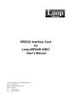
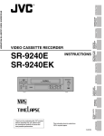
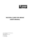
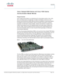
1
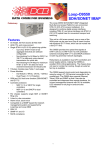
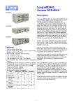
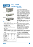
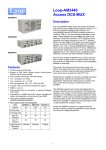
TDMoE Card for Loop-O9500R Features: y y y y y y y y y y y y y Hot pluggable interface card for O9500R Four Ethernet Ports for WAN or LAN port assignment y Two combo Gigabit Ethernet(GbE) with 2 RJ45 and 2 SFP housing y Two 10/100/1000 BaseT Ethernet y WAN 1+1 Link Aggregation (IEEE 802.1d) Max. backplane bandwidth: 8M (Nx64K bps) Jumbo Frame reach up to 10K bytes Switching & Bridging y VLAN y Concurrent 255 out of 1~4094 VLAN y Q-in-Q QoS y User configurable CoS y User configurable ToS in outgoing IP frame Pseduo-wire circuits (bundles) y For the entire card: Max.64 PW y For E1: Max. 32 PW per E1 Average 16 PW per E1 MAC learning (max. MAC table 8192 entry) Packet Delay Variation y Max. 256ms for E1 y Max. 340ms for T1 L2 switch protocol: RSTP, STP, VLAN Jitter & Wander y PPM: per G.823 Traffic IETF TDMoIP (RFC5087), SAToP (RFC4553), and CESoPSN (RFC5086) compliant RoHS Compliant Description: Loop Telecom’s TDMoE plug-in card is designed for the Loop-O9500R. TDMoE card is used to transport TDM traffic over IP network, in addition to Ethernet traffic. As the communications network migrates from TDM to IP, the TDMoE card provides a flexible and cost effective choice for the transport of legacy TDM signals. It provides four Ethernet ports with no limitation for WAN or LAN port assignment. The TDMoE card support point-to-point and point-to-multi-point voice and date application. For transport of TDM signals E1, T1, Jitter and Wander adheres to G.823 Traffic and G.823 Synchronous. 1 Ordering Information Note: RoHS compliant units are identified by the letter G appearing immediately at the end of the ordering code. Model (RoHS compliant) Loop-O9500-R-TDMoE-PPM-G Accessories User’s Manual Loop-O9500-R-TDMoE-UM Description Note TDMoE card with 2 GbE combo interfaces and 2 Ethernet interfaces (10/100/1000BaseT) plug-in module Support G.823 Traffic User’s Manual (paper copy). Note: A CD version of the manual is already included as standard package. SFP Optical Modules Please place your order using the 5-digit alphanumeric codes listed in the separate SFP Optical Module Brochure. TDMoE for Loop-O9500R Product Specifications Optical SFP Module Characteristic (please refer to SFP optical module brochure for detail) Combo Gigabit Ethernet(GbE) Interface Number of Ports 2 Speed 10/100/1000M bps Connector RJ45 for twisted pair GbE, LC for optical GbE, auto detection Gigabit Ethernet(GbE) Interface Number of Port 2 Speed 10/100/1000 BaseT Connector RJ45 Ethernet Function Basic Features MDI/MDIX for 10/100/1000M BaseT auto-sensing Ping function contained ARP Per port, programmable MAC hardware address learn limiting (max. MAC table 8192 (8k) entry) Packet Delay Variation: Packet Transparency Jumbo Frame QoS Traffic Control - Unframed T1: Up to 340 ms - Framed T1: Up to 256 ms - E1:up to 256 ms - Framed T1 with CAS: Up to 192 ms Packet transparency support for all types of packet types including IEEE 802.1q VLAN and 802.1ad (Q-in-Q) Up to 10K bytes User configurable 802.1p CoS, ToS in out going IP frame Ingress packet Rate limiting buckets per port for ethernet port Supporting Rate-based and Priority-based rate limiting for LAN port Granularity: a. From 64 Kbps to 1 Mbps in increments of 64 Kbps b. From 1 Mbps to 100 Mbps in increments of 1 Mbps c. From 100 Mbps to 1000 Mbps in increments of 10Mbps Link Aggregation Pause frame issued when the traffic exceeding the limited rate before packet dropped following IEEE802.3X WAN supports 1+1 Link Aggregation Jitter & Wander PPM: per G.823 Traffic Standard Compliance IETF IEEE TDMoIP (RFC5087), SAToP (RFC4553), CESoPSN (RFC5086) 802.1q, 802.1p, 802.1d, 802.3, 802.3u, 802.3x, 802.3z, 802.1s, 802.1w, 802.1AX 2 Application Illustrations TDMoE plug-in card in O9500R is to transport TDM traffic (voice signals/E1/ T1/ DTEs/ Ethernet) into IP Traffic. Point to Point Application (with WAN 1+1 Aggregation) 3 Point to Multipoint Application LoopTelecocom Worldwide 8F, No. 8, Hsin Ann Road, Science-Based Industrial Park Hsinchu, Taiwan 30078 Tel:+886-3-578-7696 Fax:+886-3-564-6272 www.LoopTelecom.com [email protected] LOOP TELECOMMUNICATION INTERNATIONAL, INC. ISO 9001/ISO 14001 Taipei, Taiwan 6F, No. 36, Alley 38, Lane 358, Rueiguang Road, Neihu, Taiwan 11492 Tel:+886-2-2659-0399 Fax:+886-2-2659-2325 [email protected] © 2011 Loop Telecommunication International, Inc. Version 4 25 OCT 2011 North America 8 Carrick Road Palm Beach Gardens Florida 33418, U.S.A. Tel:+1-561-627-7947 Fax:+1-561-627-6615 [email protected] Tianjin China No. 240 Baidi Road Nankai District Tianjin 300192 China Tel:+86-22-8789-4027 Fax:+86-22-8789-0344 [email protected] All Rights Reserved Subject to change without notice 4 12FXS/12FXO Voice Card for Loop-O9500R Features y y y y y y y y 12 telephone connections for FXS 12 central office or PBX line connections for FXO PLAR supported Loop start or Loop start/ground start option Battery reverse supported DID supported 12KHz and 16KHz metering pulse option. A, B, C, D signaling bit software programmable y y y y A law or μ-law coding Most signaling conventions supported Multi-color LED indicators for each port Intended for use with -48Vdc powered main units 12 Channel FXO Card 12 Channel FXS Card Description The 12FXS/12FXO plug-in cards are designed for the single slot of Loop-O9500R. It allows voice frequency interfaces to be multiplexed as a 64 Kbps DS0 signal onto a digital network. 12 FXS provides 12 voice Interfaces connect to telephones. 12FXO provides connections from telephone lines, either from a central office or from a PBX in RJ11X12 connector. Coding is either A-law or μ-law selectable by user. Most popular signaling conventions are supported, including PLAR. Ordering Information To specify options, choose from the list below. Note: RoHS compliant units are identified by the letter G appearing immediately at the end of the ordering code. Model Description Note Loop-O9500-R-12FXS-sn-pt-G 12-channel FXS plug-in card with 600/ 900 Impedance, Battery Reverse, PLAR, without Ground Start and Metering Pulse. Used with 12 RJ11. “12FXS-x” cards with H/W ver. L and F/W V.3.01.01 or newer versions. It can also be used in the Loop-AM3440-A /B/C Loop-O9500-R-12FXS-P-sn-pt-G 12-channel FXS plug-in card with 600/ 900 Impedance, Battery Reverse, PLAR, without Ground Start and Metering Pulse PLAR bit programmable function. Used with 12 RJ11. 12FXS-GMP includes all FXS card functions Loop-O9500-R-12FXS-M-pt-G 12-channel FXS plug-in card with 600/ 900 Impedance, Battery Reverse, PLAR, [Metering Pulse]. Used with 12 RJ11. Loop-O9500-R-12FXS-MPP-pt-G 12-channel FXS plug-in card with 600/ 900 Impedance, Battery Reverse, PLAR and PLAR bit programmable function, [Metering Pulse]. Used with 12 RJ11. Loop-O9500-R-12FXS-GS-pt-G 12-channel FXS plug-in card with 600/ 900 Impedance, Battery Reverse, PLAR, [Ground Start]. Used with 12 RJ11. For sn option, please refer to the table below for detail information. pt= power type For pt option, please refer to the table below fro detail information Loop-O9500-R-12FXS-GM-pt-G 12-channel FXS plug-in card with 600/ 900 Impedance, Battery Reverse, PLAR, [Ground Start, and Metering Pulse]. Used with 12 RJ11. Loop-O9500-R-12FXS-GMP-pt-G Loop- O9500-R-12FXO-G Loop- O9500-R-12FXO-M-G Loop- O9500-R-12FXO-GS-G Loop- O9500-R-12FXO-GM-G 12-channel FXS plug-in card with 600/ 900 Impedance, Battery Reverse, PLAR and PLAR bit programmable function, [Ground Start, and Metering Pulse]. Used with 12 RJ11. 12-channel FXO plug-in card with 600/900 Impedance, Battery Reverse and Loop Start. Without Ground Start and Metering Pulse. Used with 12 RJ11. 12-channel FXO plug-in card with 600/900 Impedance, Battery Reverse, Loop Start and [Metering Pulse]. Used with 12 RJ11. 12-channel FXO plug-in card with 600/900 Impedance, Battery Reverse, Loop Start and [Ground Start]. Used with 12 RJ11. 12-channel FXO plug-in card with 600/900 Impedance, Battery Reverse, Loop Start, [Ground Start] and [Metering Pulse]. Used with 12 RJ11. 12FXO-GM includes all FXO card functions 12FXO-GM includes all FXO Card functions. “12FXO-x” cards with H/W ver. G and F/W V2.01.01 or newer versions. It can also be used in the AM3440-A /B/C Accessories User’s Manual Loop-O9500-R-FXSFXO-UM User’s Manual (paper copy). Note: A CD version of the manual is already included as standard package. For 12-channel FXS Card: Where sn is used to select special function. If this option is not required, omit the sn field in the ordering code. sn = Description Note S1 FXS Loop Feed = -48 Vdc with 35 mA current limit S4 Remove alarm tone S5 Double ring tone transmit Note: For sn (special function), please contact your nearest Loop sales representative. Where pt is used to select the following functions. pt= Description PWR complied with -48 Vdc (SD48) power modules PWRIE1613 complied with IEEE1613 standard, and with -48 Vdc (SD48) power modules Note 12FXS/FXO Product Specifications Voice Card (12FXS, 12FXO) Connector Alarm Conditioning Encoding AC Impedance Longitudinal Conversion Loss Cross talk measure Gain Adjustment Signal/ Distortion Frequency Response Idle Channel Noise Variation of Gain FXO Twelve RJ11 CGA busy after 2.5 seconds of LOS, LOF A-law or μ-law, user selectable together for all Balanced 600 or 900 ohms (selectable together for all) > 46dB Max -70dBm0 -21 to +10 dB / 0.1dB step transmit & receive > 25dB with 1004 Hz, 0dBm input - 0.25 to -1 dB from 300 to 3400 Hz, coincide with ITU-T G.712 Max. –65 dBm0p ±0.5dB Ringing REN 0.5B (AC) Detectable Ringing 25 Vrms Loop Resistance ≦1800 Ω DC Impedance (ON-HOOK) > 1M Ω DC Impedance (OFF-HOOK) 235 Ω@ 25 mA feed 90 Ω@ 100 mA feed FXS Loop Feed -48Vdc with 25mA current limit per port Jumper Selectable: 25mA, 30mA, 35mA FXS signalling Normal / Automatic Ring down FXS Ringing 1 REN at 5K meters per port 16.7Hz, 20Hz, 25Hz, 50Hz, user selectable for all ports 38 to 85 Vrms (sine wave), 76 Vrms for default Ring Voltage 2 sec on 4 sec off, or 1 sec on 2 sec off optional for PLAR Signaling Loop Start, DTMF, pulse, PLAR, Battery Reverse Optional Signaling (for special Ground Start, Metering pulse (12 KHz, 16 KHz), and P( in PLAR mode, PLAR signalling order) bits are programmable. Signaling Bit A,B,C,D Programable bit y All in-band signaling tones are carried transparently by the digitizing process. y Customer is responsible for in-band signaling compatibility between a telephone and a switch, or between a PBX and a switch. Application Illustrations Digital C.O. WAN PLAR ON E1 / T1 Loop-O9500R FXS Card Metering Pulse (12KHz/ 16KHz) CO switch Support Telephones GND-start (Caller ID) Hot line Pay Phone Modem WAN Loop-O9500R Digital C.O. E1 / T1 FXO Card Pulse Detect 12KHz/ 16KHz CO switch Support pay phone LoopTelecom.com Worldwide Co switch PABX Support GND-start LOOP TELECOMMUNICATION INTERNATIONAL, INC. ISO 9001/ISO 14001 8F, No. 8, Hsin Ann Road, Science-Based Industrial Park Hsinchu, Taiwan 300 Tel:+886-3-578-7696 Fax:+886-3-564-6272 www.LoopTelecom.com [email protected] Taipei, Taiwan 6F, No. 36, Alley 38, Lane 358, Rueiguang Road, Neihu, Taiwan 11492 Tel:+886-2-2659-0399 Fax:+886-2-2659-2325 [email protected] © 2012 Loop Telecommunication International, Inc. Version 5 21 MAR 2012 North America 8 Carrick Road Palm Beach Gardens Florida 33418, U.S.A. Tel:+1-561-627-7947 Fax:+1-561-627-6615 [email protected] Tianjin China No. 240 Baidi Road Nankai District Tianjin 300192 China Tel:+86-22-8789-4027 Fax:+86-22-8789-0344 [email protected] All Rights Reserved Subject to change without notice 24 FXS/FXO Voice Card for Loop-O9500R Features: y y y y y y y y 24 telephone connections for FXS 24 central office or PBX line connections for FXO PLAR supported Loop start or Loop start/ground start option Battery reverse supported DID supported 12KHz and 16KHz metering pulse option A, B, C, D signaling bit software programmable y y y y y y A-law or μ-law coding Most signaling conventions supported Multi-color LED indicators for each card Intended for use with -48Vdc powered main units RJ 21X (Telco 50 pin) Connector Occupies two full size slot (slots 11~16) of O9500R device. Description The 24FXS/24FXO plug-in cards are designed for the dual slot of Loop-O9500R device. It allows voice frequency interfaces to be multiplexed as a 64 Kbps DS0 signal onto a digital network. The 24FXS provides 24 voice interfaces connect to telephones. The 24FXO provide connections from telephone lines, either from a central office or from a PBX in a single RJ21X (Telco 50pin) connector. Coding is either A-law or μ-law selectable by user. Most popular signaling conventions are supported, including PLAR. Ordering Information To specify options, choose from the list below. Note: RoHS compliant units are identified by the letter G appearing immediately at the end of the ordering code. Model Description Note (RoHS compliant) 24-channel FXS plug-in card with 600/900 Impedance, Battery Reverse, Loop Start and PLAR Without Ground Start and Metering Pulse Loop-O9500-R-24FXS-sn-pt-G Loop-O9500-R-24FXS-P-sn-pt-G Loop-O9500-R-24FXS-M-pt-G Loop-O9500-R-24FXS-MPP-pt-G Loop-O9500-R-24FXS-GS-pt-G Loop-O9500-R-24FXS-GM-pt-G Loop-O9500-R-24FXS-GMP-pt-G Loop-O9500-R-24FXO-pt-G Loop-O9500-R-24FXO-M-pt-G Loop-O9500-R-24FXO-GS-pt-G Loop-O9500-R-24FXO-GM-pt-G Accessories User’s Manual Loop-O9500-R-FXSFXO-UM 24-channel FXS plug-in card with 600/900 Impedance, Battery Reverse, Loop Start, PLAR and [PLAR bit programmable]. Without Ground Start and Metering Pulse 24-channel FXS plug-in card with 600/900 Impedance, Battery Reverse, Loop Start, PLAR and [Metering Pulse]. 24-channel FXS plug-in card with 600/900 Impedance, Battery Reverse, Loop Start, PLAR, [PLAR bit programmable] and [Metering Pulse]. 24-channel FXS plug-in card with 600/900 Impedance, Battery Reverse, Loop Start, PLAR and [Ground Start]. 24-channel FXS plug-in card e with 600/900 Impedance, Battery Reverse, Loop Start, PLAR, [Ground Start] and [Metering Pulse]. 24-channel FXS plug-in card with 600/900 Impedance, Battery Reverse, Loop Start, PLAR, [PLAR bit programmable], [Ground Start] and [Metering Pulse]. 24-channel FXO plug-in module with 600/ 900 Impedance, Battery Reverse, without Ground Start and Metering Pulse 24-channel FXO plug-in module with 600/ 900 Impedance, Battery Reverse, [Metering Pulse] 24-channel FXO plug-in module with 600/ 900 Impedance, Battery Reverse, [Ground Start] 24-channel FXO plug-in module with 600/ 900 Impedance, Battery Reverse, [Ground Start, and Metering Pulse] 24FXS-GMP includes all FXS card functions. These cards will occupy two slots. These cards can also be used in the Loop-AM3440-A /B/C For sn option, please refer to the table below for detail information pt=power type For pt option, please refer to the table below fro detail information 24FXO-GM includes all FXO card functions User’s Manual (paper copy). Note: A CD version of the manual is already included as standard package. For 24-channel FXS card: Where sn is used to select special function. If this option is not required, omit the sn field in the ordering code. sn = Description Note S1 FXS Loop Feed = -48 Vdc with 35 mA current limit S4 Remove alarm tone S5 Double ring tone transmit Note: For sn (special function), please contact your nearest Loop sales representative. Where pt is used to select the following functions. pt= Description PWR complied with -48 Vdc (SD48) power modules PWRIE1613 complied with IEEE1613 standard, and with -48 Vdc (SD48) power modules Note 24 FXS/FXO Product Specifications Voice Card (24FXS, 24FXO) Connector Alarm Conditioning Encoding AC Impedance Longitudinal Conversion Loss Cross talk measure Gain Adjustment Signal/ Distortion Frequency Response Idle Channel Noise Variation of Gain FXO One RJ21X CGA busy after 2.5 seconds of LOS, LOF A-law or μ-law, user selectable together for all Balanced 600 or 900 ohms (selectable together for all) > 46dB Max -70dBm0 -21 to +10 dB / 0.1dB step transmit & receive > 25dB with 1004 Hz, 0dBm input - 0.25 to -1 dB from 300 to 3400 Hz, coincide with ITU-T G.712 Max. –65 dBm0p ±0.5dB Ringing REN 0.5B (AC) Detectable Ringing 25 Vrms Loop Resistance ≦1800 Ω DC Impedance (ON-HOOK) > 1M Ω DC Impedance (OFF-HOOK) 235 Ω@ 25 mA feed 90 Ω@ 100 mA feed FXS Loop Feed -48Vdc with 25mA current limit per port Jumper Selectable: 25mA, 30mA, 35mA FXS signalling Normal / Automatic Ring down FXS Ringing 1 REN at 5K meters per port 16.7Hz, 20Hz, 25Hz, 50Hz, user selectable for all ports 38 to 85 Vrms (sine wave), 76 Vrms for default Ring Voltage 2 sec on 4 sec off, or 1 sec on 2 sec off optional for PLAR Signaling Loop Start, DTMF, pulse, PLAR, Battery Reverse Optional Signaling (for special Ground Start, Metering pulse (12 KHz, 16 KHz), and P( in PLAR mode, PLAR signalling order) bits are programmable. Signaling Bit A,B,C,D Programable bit y All in-band signaling tones are carried transparently by the digitizing process. y Customer is responsible for in-band signaling compatibility between a telephone and a switch, or between a PBX and a switch. Application Illustrations Digital C.O. WAN PLAR ON E1 / T1 Loop-O9500R FXS Card Metering Pulse (12KHz/ 16KHz) CO switch Support Telephones GND-start (Caller ID) Hot line Pay Phone Modem Digital C.O. WAN Loop-O9500R E1 / T1 FXO Card Pulse Detect 12KHz/ 16KHz CO switch Support pay phone LoopTelecom.com Co switch Support GND-start PABX LOOP TELECOMMUNICATION INTERNATIONAL, INC. ISO 9001/ISO 14001 Worldwide Taipei, Taiwan North America Tianjin China 8F, No. 8, Hsin Ann Road, Science-Based Industrial Park Hsinchu, Taiwan 300 Tel:+886-3-578-7696 Fax:+886-3-564-6272 www.LoopTelecom.com [email protected] 6F, No. 36, Alley 38, Lane 358, Rueiguang Road, Neihu, Taiwan 11492 Tel:+886-2-2659-0399 Fax:+886-2-2659-2325 [email protected] 8 Carrick Road Palm Beach Gardens Florida 33418, U.S.A. Tel:+1-561-627-7947 Fax:+1-561-627-6615 [email protected] No. 240 Baidi Road Nankai District Tianjin 300192 China Tel:+86-22-8789-4027 Fax:+86-22-8789-0344 [email protected] © 2010 Loop Telecommunication International, Inc. Version 4 16 MAR 2010 All Rights Reserved Subject to change without notice 4E1/T1 Interface Card for Loop-O9500R Features z Contains four E1/T1 Interface. z Usable as a CSU/DSU, T1 to E1 converter. z Full TSI capability among all time slots in the main unit z Remote diagnostics z Single LED indicator per port z Software field upgradable Description Loop Telecom’s QT1/QE1 plug-in cards are a series of 2 different plug-in cards designed for the Loop-O9500R. They allow each DS0 time slot in QT1 or QE1 interfaces to be interchanged and multiplexed onto a digital network. Continuous error checking, performance polling, and in-service diagnostics are provided through the main controller of the Loop-O9500R. In addition, an LED on the plug-in provides status indication. Ordering Information To specify options, choose from list below: Model (RoHS compliant) Main Unit Loop-O9500-R-4E1-cc-G Loop-O9500-R-4T1-G Description 4-channel E1 plug-in card. For cc option, please refer to the table below for detail information 4-channel T1 plug-in card Note This card can also be used in the Loop-AM3440-A /B/C. This card can also be used in the Loop-AM3440-A /B/C. Accessories User’s Manual (All User’s Manuals are RoHS compliant) Loop-O9500-R-4E1T1-UM Optional hard-copy (paper) User’s Manual. A CD version of the manual is already included as a standard package. Where cc is used to select connector: cc = RJ RJ48C connector BNC BNC connector Description Note Product Specifications for 4E1/T1 Interface Card Network Line Interface – 4E1 Line Rate 2.048 Mbps ± 50 ppm Line Code AMI or HDB3 Input Signal ITU G.703 Output Signal ITU G.703 Network Line Interface - 4T1 Line Rate 1.544 Mbps ± 32 ppm Line Code AMI or B8ZS Input Signal DSX-1 0 dB to -30 dB w/ALBO Framing Connector Electrical Jitter ITU G.704 BNC/RJ48C 75 ohm Coax/120 ohm twisted pair ITU G.823 Output Signal Framing Connector DSX1w/0, -7.5, -15 dB LBO D4/ESF (selectable) RJ48C Application Illustration All Other Cards Loop-O9500R QE1/QT1 WAN LoopTelecom.com Worldwide LOOP TELECOMMUNICATION INTERNATIONAL, INC. ISO 9001/ISO 14001 8F, No. 8, Hsin Ann Road, Science-Based Industrial Park Hsinchu, Taiwan 30078 Tel:+886-3-578-7696 Fax:+886-3-564-6272 www.LoopTelecom.com [email protected] Taipei, Taiwan 6F, No. 36, Alley 38, Lane 358, Rueiguang Road, Neihu, Taiwan 11492 Tel:+886-2-2659-0399 Fax:+886-2-2659-2325 [email protected] © 2009 Loop Telecommunication International, Inc. Version v1 08 MAR 2009 North America 8 Carrick Road Palm Beach Gardens Florida 33418, U.S.A. Tel:+1-561-627-7947 Fax:+1-561-627-6615 [email protected] Tianjin China No. 240 Baidi Road Nankai District Tianjin 300192 China Tel:+86-22-8789-4027 Fax:+86-22-8789-0344 [email protected] All Rights Reserved Subject to change without notice 7 Fiber Optical Interface for Loop-O9500R Features Hot-pluggable high-speed interface card for z O9500R IMAP Aggregate ports z y 7 aggregate ports with SFP housing, each supports 4 E1s. Port Protection z y Line 1+1 (requires two cards) y Switching time within 50ms z Automatic Laser Shutdown (ALS) function z Single mode and multi-mode fiber modules z Local and remote FOM alarm indication Description The Loop-O9500R 7 FOM card is a high-speed module that can connect with the AM3440 series and Loop-O9310-E1 using Loop proprietary FOM interface. Each card has 7 FOM interfaces. Each FOM interface supports up to 4 E1 aggregate channels. The 7 FOM card is E1 mode configurable and supports Tributary Line 1+1 Protection. When protection enable with 1+1, the O9500R can support up to 14 ports of FOM. Ordering Information Note: RoHS compliant unit is identified by the letter G appearing immediately at the end of the ordering code. Model Loop-O9500-R-7FOM-G Description 7 Ports Fiber Optical Interface with 7 SFP housings (SFP not included) Note This card can also be used in the Loop-O9400-R Accessories SFP Optical Modules Please place your order using the 5-digit alphanumeric codes listed in the separate SFP Optical Module Brochure. User’s Manual Loop-O9500-R-7FOM-UM User’s Manual (paper, hard copy-optional). A CD version of the manual is already included as standard package. Product Specifications Fiber Optical Interface Port number 7 Source Laser Wavelength 1310 ± 50 nm, 1550 ± 40 nm Optical Line Rate 38.84Mbps Connector SFP housing with LC type Line Code 1 Scrambled NRZ Reach 2~240 Km (please refer to the SFP brochure for detail) Protection 1+1 Line Protection Optical Fiber Interface Characteristics (Pleaer refer to SFP optical brochure for detail) Diagnostics Test Optical Fiber E1 Test Pattern Local and remote loopbacks To optical direction or backplane direction Application Illustrations LoopTelecom.com LOOP TELECOMMUNICATION INTERNATIONAL, INC. ISO 9001/ISO 14001 Worldwide Taipei, Taiwan North America Tianjin China 8F, No. 8, Hsin Ann Road, Science-Based Industrial Park Hsinchu, Taiwan 30078 Tel:+886-3-578-7696 Fax:+886-3-564-6272 www.LoopTelecom.com [email protected] 6F, No. 36, Alley 38, Lane 358, Rueiguang Road, Neihu, Taiwan 11492 Tel:+886-2-2659-0399 Fax:+886-2-2659-2325 [email protected] 8 Carrick Road Palm Beach Gardens Florida 33418, U.S.A. Tel:+1-561-627-7947 Fax:+1-561-627-6615 [email protected] No. 240 Baidi Road Nankai District Tianjin 300192 China Tel:+86-22-8789-4027 Fax:+86-22-8789-0344 [email protected] © 2011 Loop Telecommunication International, Inc. Version 2 25 OCT 2011 All Rights Reserved Subject to change without notice 2 8RS232 Interface Card for Loop-O9500R Features z z z z z z z Support X.50 division 2 and X.54 Single slot Two card types: 8 RJ48 only card: 8 ports RS232 Async 2 RJ48 + 2 DB44 card: Up to 4 ports RS232 Sync + 4 ports RS232 Async LED status indicator Hot swappable Support Async rates from 600bps to 38400 bps Support Sync rates from 600bps to 64000 bps Description The 8RS232 Interface Card for Loop-O9500R has 8 interface ports. For the RJ version, 8 RJ48 connectors are available in Asynchronous mode only. For the DB version, 2 RJ48 provide 2 ports and 2 DB44 connectors provide 3 ports each. Two cables are included. Each cable converts from DB44 connector to two DB25 and one DB9 connectors. For Asynchronous signals, the card can be used in either INDEPENDENT mode or MUX mode. In the INDEPENDENT mode, each of the 8 Asynchronous ports up to 38.4 Kb/s rate, is assigned a separate 64 Kb/s channel. In the MUX mode, up to 5 ports, each up to 9.6 Kb/s, can share a single 64 Kb/s channel. The rest 3 ports will be multiplexed to another 64Kb/s channel. For Synchronous signals, only four of the ports can be used, leaving another 4 ports as Asynchronous. In the INDEPENDENT mode, each of the 4 Synchronous ports can be up to 64 Kb/s. The rest of the 4 Asynchronous ports, each up to 38.4 Kb/s rate, is assigned a separate 64 Kb/s channel per port. In the MUX mode, the 4 Synchronous ports, each up to 9.6 Kb/s, share a single 64 Kb/s channel. The other 3 Asynchronous ports will be multiplexed to another 64Kb/s channel. The 8RS232 Interface Card uses the multiplexing format defined in ITU-T X.50 Div.2 and in X.54 for rates below 64kbps. For 64kbps transport, standard RS232 format is used. In the INDEPENDENT mode when only one subrate signal is transported, the unused bandwidth is filled with "1s". Ordering Information To specify options, choose from list below. Note: RoHS compliant units are identified by the letter G appearing immediately at the end of ordering code. Model Main Unit Loop-O9500-R-8RS232-RJ-G Description Loop-O9500-R-8RS232-DB-G Note 8-port RS232 plug-in card with X.50 subrate multiplexing scheme and X.54 encoding, with 8 RJ48 connectors for 8 RS232 Async ports This card can also be used in the Loop-AM3440-A /B/C. 8-port RS232 plug-in card with X.50 subrate multiplexing scheme and X.54 encoding, with 2 RJ48 connectors and 2 DB44 connectors for Async and Sync ports Two conversion cables are included. (Each cable has one DB44 connector to one DB9 and two DB25 connectors). This card can also be used in the Loop-AM3440-A /B/C. Conversion Cables(All conversion cables are RoHS compliant) Loop-ACC-CAB-DB44M- DSUB-44 pin/Male to two DSUB-25 100-2DB25F-1DB09F-DB pin/Female- one DSBU-9 pin/Female Used in Loop-O9500-R-8RS232-DB-G plug-in card Length 100cm Accessories User’s Manual (All User’s Manuals are RoHS compliant) Loop-O9500-R-8RS232-UM Optional hard-copy (paper) User’s Manual. A CD version of the manual is already included as a standard package. Product Specifications for DTE Interface Cards DTE(RS232-X.50 mux. 8-port) Interface (RS232/V.24) Data Port MUX Data Rate Up to twelve 8-port RS232 cards Maximum 5 subrate port per 64K bps Mux mode Asynchronous Independent mode Mux mode Synchronous Independent mode 0.6K, 1.2K, 2.4K, 4.8K, 9.6K 0.6K, 1.2K, 2.4K, 4.8K, 9.6K, 19.2K, 38.4K 0.6K, 1.2K, 2.4K, 4.8K, 9.6K 0.6K, 1.2K, 2.4K, 4.8K, 9.6K, 19.2K, 38.4K, 48K, 64K Port Number Card Type Eight RJ48 1 2 3 4 5 6 7 8 Async Async Async Async Async Async Async Async Async/Sync Async/Sync Async Async Async Two DB44 + Two RJ48 Async/Sync Async/Sync Async Connector Eight RJ48 (port 1 to port 8) DB44 (port1,port2,port3), DB44 (port4,port5,port6), RJ48 (port7) and RJ48(port8) Conversion Cable A three-into-one conversion cable adapts the DB44 connector to 3 connecters (one DB9S and two Electrical RS232 Interface, DCE DB25S) Application Illustration LoopTelecom.com LOOP TELECOMMUNICATION INTERNATIONAL, INC. ISO 9001/ISO 14001 Worldwide Taipei, Taiwan North America Tianjin China 8F, No. 8, Hsin Ann Road, Science-Based Industrial Park Hsinchu, Taiwan 30078 Tel:+886-3-578-7696 Fax:+886-3-564-6272 www.LoopTelecom.com [email protected] 6F, No. 36, Alley 38, Lane 358, Rueiguang Road, Neihu, Taiwan 11492 Tel:+886-2-2659-0399 Fax:+886-2-2659-2325 [email protected] 8 Carrick Road Palm Beach Gardens Florida 33418, U.S.A. Tel:+1-561-627-7947 Fax:+1-561-627-6615 [email protected] No. 240 Baidi Road Nankai District Tianjin 300192 China Tel:+86-22-8789-4027 Fax:+86-22-8789-0344 [email protected] © 2010 Loop Telecommunication International, Inc. Version 2 28 MAY 2010 All Rights Reserved Subject to change without notice G.703 Interface Card for Loop-O9500R Features y 8-port G.703 plug-in card, single slot to O9500R chassis y Support data rate at 64 Kbps y Support G.703 transmission over balanced wire y Eight LED indications per card Description The G.703 plug-in card is designed for the single slot of Loop-O9500R. This interface supports 64 Kbps data transport using the G.703 co-directional timing standard. The G.703 plug-in card supports diagnostics and alarm setup using a local or remote terminal connected to the main unit. This allows in-service diagnostics and fault isolation. Ordering Information To specify options, choose from the list below: Note: RoHS compliant units are identified by the letter G appearing immediately at the end of ordering code. Model Loop-O9500-R-8CD-G Accessories User’s Manual Loop-O9500-R-8CD-UM Description 8-channel G.703 plug-in card at 64 Kbps data rate User’s Manual (paper copy). Note: A CD version of the manual is already included as standard package. Product Specifications for G.703 Interface Card Interface Connector Line Distance Loopback Note This card can also be used in the Loop-AM3440-A /B/C. ITU G.703 64 Kbps co-directional interface 120ohm, RJ48 Up to 500 meters DTE Payload Loopback, Local Loopback Application Illustration Loop-O9500R G.703 G.703 64Kbps LoopTelecom.com Worldwide WAN LOOP TELECOMMUNICATION INTERNATIONAL, INC. ISO 9001/ISO 14001 8F, No. 8, Hsin Ann Road, Science-Based Industrial Park Hsinchu, Taiwan 30078 Tel:+886-3-578-7696 Fax:+886-3-564-6272 www.LoopTelecom.com [email protected] Taipei, Taiwan 6F, No. 36, Alley 38, Lane 358, Rueiguang Road, Neihu, Taiwan 11492 Tel:+886-2-2659-0399 Fax:+886-2-2659-2325 [email protected] © 2009 Loop Telecommunication International, Inc. Version 1 08 MAR 2009 North America 8 Carrick Road Palm Beach Gardens Florida 33418, U.S.A. Tel:+1-561-627-7947 Fax:+1-561-627-6615 [email protected] Tianjin China No. 240 Baidi Road Nankai District Tianjin 300192 China Tel:+86-22-8789-4027 Fax:+86-22-8789-0344 [email protected] All Rights Reserved Subject to change without notice Dry Contact Interface Card for Loop-O9500R Features z z z Two Dry Contact plug-in card are available Dry Contact Card Dry Contact type B card Dry Contact Inputs - 8 pairs per card (2 ports per card, 4 pairs per port) - Connector: RJ45 - Collect dry contact input signals and send alarm traps via SNMP port or inband to LoopView EMS management system - Collect dry contact to be transferred via the E1 or fiber optic cable to a dry relay contact output Dry Contact Dry Contact-B Dry Contact Outputs - 8 pairs per card - Connector: Screw - Enable dry contact output signals through instructions via SNMP port or inband to LoopView EMS management system - Enable dry contact from the E1 or fiber cable to a dry relay contact output - Support Normal Closed/Open Description Loop Telecom’s Dry Contact card and Dry Contact type B plug-in card are designed for the Loop-O9500R. These Dry Contact cards, which can be assigned to 2 DS0 time slots or 16 DS0 time slots, are used for (1) collecting alarm inputs from non-SNMP devices and issuing alarm via SNMP trap, (2) sending commands to close remote contacts for relay devices, and (3) repeat a remote contact closure with a local contact closure. The difference between Dry Contact and Dry Contact type B interface cards is the higher voltage for type B interface card. These cards are used to detect remote contact closures activated by alarms and to provide remote contact closures to control network operation where needed. When 2 DS0 time slots are chosen to carry the dry contact signals, 8 bits of one time slot carry the input contact status, and 8 bits of the other carry the output contact commands. When 16 DS0 time slots are chosen to carry the dry contact signals, one bit of each of 8 DS0 time slot carry the input contact status, and one bit of each of other 8 DS0 carry the output commands. Ordering Information To specify options, choose from list below: Note: RoHS compliant units are identified by the letter G appearing immediately at the end of the ordering code. Model Description Note Main Unit Loop-O9500-R-8DC-G 8-channel dry contact I/O plug-in card Loop- O9500-R-8DCB-G 8-channel dry contact type B plug-in card with maximum voltage 220 Vdc or 250 Vac These cards can also be used in the Loop-AM3440-A /B/C. Accessories User’s Manual (All User’s Manuals are RoHS compliant) Loop-O9500-R-8DC-UM Optional hard-copy (paper) User’s Manual. A CD version of the manual is already included as a standard package. 1 Product Specifications for Dry Contact Card Dry Contact I/O card (8DC) Inputs 8-channel 2-port per card, 4-pair per port Connector RJ45 Internal Resistance 1K Activation Current 3 ma Deactivation Current 1.5 ma Allowable Current 4 ma Outputs 8-channel Connector Initial Insulation Resistance Max. Current Max. Voltage 8-pair per card Screw type Min. 100M ohm (at 500 Vdc) 5A 100 Vdc, 250 Vac Dry Contact Type B Interface Inputs 8-channel 2-port per card, 4-pair per port Connector RJ45 Internal Resistance 100 K Activation Current 3 ma Deactivation Current 1.5 ma Allowable Current 4 ma Outputs 8-channel Connector Initial Insulation Resistance Max. Current Max. Voltage 8-pair per card Screw type Min. 1000M ohm (at 500 Vdc) 2A 220 Vdc, 250 Vac Application Illustrations Dry Contact Input Application - SNMP Trap When the alarm occurs, this is detected by the dry contact input. The dry contact card will send alarm trap to Control Center via SNMP port for management. Dry Contact Output Application - Remote Contact Control From the Control Center, any dry contact can be made to close by remote commands 2 Point to Point Application — Using both input and output dry contacts Using one DS0 for alarm input and one DS0 for alarm out put, and vice versa. When the alarm occurs, it will send alarm trap via SNMP port for management. Also, the dry contact inputs at local site can be detected and transmitted to the dry contact outputs at the control site. Point to Multi-Point Application Using the 16 DS0 to carry the alarm input and alarm output (8 DS0 for input, 8 DS0 for output), and vice versa. When the any of the assigned of the alarm occurs, it will send alarm trap via SNMP port for management. From the central management point, all dry contact outputs can be controlled. . LoopTelecom.com Worldwide LOOP TELECOMMUNICATION INTERNATIONAL, INC. ISO 9001/ISO 14001 8F, No. 8, Hsin Ann Road, Science-Based Industrial Park Hsinchu, Taiwan 30078 Tel:+886-3-578-7696 Fax:+886-3-564-6272 www.LoopTelecom.com [email protected] Taipei, Taiwan 6F, No. 36, Alley 38, Lane 358, Rueiguang Road, Neihu, Taiwan 11492 Tel:+886-2-2659-0399 Fax:+886-2-2659-2325 [email protected] North America 8 Carrick Road Palm Beach Gardens Florida 33418, U.S.A. Tel:+1-561-627-7947 Fax:+1-561-627-6615 [email protected] © 2009 Loop Telecommunication International, Inc. Version 2 03 DEC 2009 Tianjin China No. 240 Baidi Road Nankai District Tianjin 300192 China Tel:+86-22-8789-4027 Fax:+86-22-8789-0344 [email protected] All Rights Reserved Subject to change without notice 3 V.35/ X.21/V.36/RS449/EIA530/ RS232 Interface Card for Loop-O9500R Features z z z z Maximum data rate of n x 64K (n ≤ 32) Mapping to any sequential time slots Supports ANSI V.54 Built-in BERT for diagnostics Description The V.35/V.36/EIA530/RS232/X.21 plug-in cards are a series of 4 different plug-in cards designed for the dual slot of Loop-O9500R. They allow multiplexing of n x 64 Kbps data to multiples of DS0 time slots onto a digital network. An LED on the front panel of the Loop-O9500R provides status indication. Ordering Information To specify options, choose from the list below. Note: RoHS compliant units are identified by the letter G appearing immediately at the end of the ordering code. Model (RoHS compliant) Loop-O9500-R-6X21A-G Description 6-channel X.21/V.11 card with DB15 connector Loop-O9500-R -6V35A-G 6-channel V.35 plug-in card with DB25S connector, for M34. (2Mbits per channel) Please order conversion cable connector below. Loop-O9500-R -6V36A-G 6-channel V.36 card with DB25 connector via conversion cable to DB37 6-channel EIA530 plug-in card with DB25 connector 6-channel EIA530/RS449 plug-in card with DB25 connector via conversion cable to DB37 Loop-O9500-R-6E530A-G Loop-O9500-R-6RS449A-G Accessories Conversion Cables(All conversion cables are RoHS compliant) Loop-ACC-CAB-DB25M-30- DSUB-25pin/Male to M34/Female V.35 Conversion cable 1M34F Length: 30 cm Loop-ACC-CAB-DB25M-301DB37F User’s Manual Loop-O9500-R-DTE-UM DSUB-25pin/Male to DSUB-37/Female RS449 Conversion cable Length: 30 cm Note These cards will occupy two slots. These cards can also be used in the Loop-AM3440-A /B/C. Used in Loop-O9500-R-6V35A-G plug-in card Used in Loop-O9500-R-6V36A-G and Loop-O9500-R-6R449A-G plug-in cards User’s Manual (paper copy). Note: A CD version of the manual is already included as standard package. Product Specifications for DTE Interface Cards DTE(X.21/V.11) Interface (-6X21A) Data Port Up to six 6-port DTE X.21 card; 1-port DTE X.21 card (future option) Data Rate 56 or 64 Kbps, n = 1 to 32 Connector DB15 DTE (V.35/ V.36) Interface (6V35A/6V36A) Data Port Up to six 6-port DTE V.35/ V.36 cards Data Rate 56 or 64 Kbps, n = 1 to 32 Connector For V.35 card: DB25S (optional conversion cable DB25S to M34 connector) For V.36 card::DB25S (optional conversion cable DB25S to DB37 connector) DTE (EIA530/RS449) Interface (6 EIA530A/6RS449A) Data Port Up to six 6-port EIA530 DTE card Data Rate 56 or 64 Kbps, n = 1 to 32 Connector DB25S (optional conversion cable DB25S male to DB37 female connector for RS449) Application Illustration Loop-O9500R V.35 / X.21/ V.36 / RS449 / E1530 / RS232 Interfaces E1 / T1 /G.shdsl Interfaces WAN Loop-IP 6610 LoopTelecom.com Worldwide LOOP TELECOMMUNICATION INTERNATIONAL, INC. ISO 9001/ISO 14001 8F, No. 8, Hsin Ann Road, Science-Based Industrial Park Hsinchu, Taiwan 30078 Tel:+886-3-578-7696 Fax:+886-3-564-6272 www.LoopTelecom.com [email protected] Taipei, Taiwan 6F, No. 36, Alley 38, Lane 358, Rueiguang Road, Neihu, Taiwan 11492 Tel:+886-2-2659-0399 Fax:+886-2-2659-2325 [email protected] © 2009 Loop Telecommunication International, Inc. Version 1 08 MAR 2009 North America 8 Carrick Road Palm Beach Gardens Florida 33418, U.S.A. Tel:+1-561-627-7947 Fax:+1-561-627-6615 [email protected] Tianjin China No. 240 Baidi Road Nankai District Tianjin 300192 China Tel:+86-22-8789-4027 Fax:+86-22-8789-0344 [email protected] All Rights Reserved Subject to change without notice E&M Voice Card for Loop-O9500R Features z RJ45 × 8 connector for E&M z E&M signaling types are supported: Type 1, Type 2, Type 3, Type 4 and Type 5. z Programmable gain setting per-port z A side and B side supported (A side is exchange side, B side is carrier side) z 2 wire, 4 wire supported z Transmit only (TO) type supported z law or μ-law coding z Intended for use with -48Vdc powered main units. Description Loop Telecom’s E&M plug-in card is designed for the Loop-O9500R device. It allows 8 ports E&M interfaces to be multiplexed to 64 Kbps DS0 signals. It can also be used as TO (Transmit Only) Voice coding can be selected as either A-law or μ-law. This unit can be used on systems running -48Vdc power supply. Ordering Information To specify options, choose from list below: Model (RoHS compliant) Loop-O9500-R-8EM-x-G Description 8-channel 2W/4W E&M plug-in card Note “8EM” card with H/W ver. F (and later versions), F/W V4.01.01 (and later versions) can also be used in the LoopAM3440-A /B/C. For x option, please refer to the table below. Accessories User’s Manual Loop-O9500-R-8EM-UM User’s Manual (paper copy). Note: A CD version of the manual is already included as standard package. Where x is used to select signaling bits type and special functions: 8EM x= E A R S AR S4 S5 S6 Description Follows ETSI signaling bits Follows ANSI signaling bits Reverse for ON-HOOK and OFF-HOOK signaling bits exchange Follows customer’s special bit or function assignment Follows ANSI signaling bits and reverse bit Disable the function of the test button Forcing all ports to be OFF-HOOK when an alarm occurs Forcing all ports to be ON-HOOK when an alarm occurs Note Jumper selectable for all channels Note: For S (customer‘s special bit), please refer to SFP brochure or contact your nearest Loop sales representative. Product Specification for E&M Interface Card Connector Alarm Conditioning Encoding Impedance Longitudinal Conversion Loss Longitudinal Balance Gain Adjustment (Per-port setting) Eight RJ45 CGA busy after 2.5 seconds of LOS, LOF A-law or μ-law, user selectable together for all Balanced 600 or 900 ohms > 46dB > 63dB -10 to +7 dB / 0.1dB step for transmit (D/A) gain -10 to +14 dB / 0.1dB step for receive (A/D) gain I/O voice power range A/D digital input level: -66 dBm (0.00039 Vrms) ~ + 3 dBm (1.09 Vrms) D/A analog output level: -66 dBm (0.00039 Vrms) ~ + 7 dBm (1.74 Vrms) Signal/Distortion > 25dB with 1004 Hz, 0dBm input Frequency Response +0.5 to -0.9 dB from 300 to 3400 Hz Carrier connection Side A ( exchange side) and Side B (carrier side) setup by side switch Idle Channel Noise Max. –65 dBm0p wire mode 2 wire and 4 wire (programmable) Signaling Type 1, Type 2, Type 3, Type 4, and Type 5, Transmit only (programmable) Modems Full compatibility with V.90 modems All in-band signaling tones are carried transparently by the digitizing process. Customer is responsible for in-band signaling compatibility between a telephone and a switch, or between a PBX and a switch. Application Illustration Modem Switch Loop-O9500R EM Card Switch E1/T1 Card Loop-O9500R E1/T1 E1/T1 Card EM Card Modem PBX Microwave System Standard E&M Interface Equipment Link or Tandem Connection LoopTelecom.com Worldwide LOOP TELECOMMUNICATION INTERNATIONAL, INC. ISO 9001/ISO 14001 8F, No. 8, Hsin Ann Road, Science-Based Industrial Park Hsinchu, Taiwan 30078 Tel:+886-3-578-7696 Fax:+886-3-564-6272 www.LoopTelecom.com [email protected] Taipei, Taiwan 6F, No. 36, Alley 38, Lane 358, Rueiguang Road, Neihu, Taiwan 11492 Tel:+886-2-2659-0399 Fax:+886-2-2659-2325 [email protected] © 2011 Loop Telecommunication International, Inc. Version 3 28 MAR 2011 North America 8 Carrick Road Palm Beach Gardens Florida 33418, U.S.A. Tel:+1-561-627-7947 Fax:+1-561-627-6615 [email protected] Tianjin China No. 240 Baidi Road Nankai District Tianjin 300192 China Tel:+86-22-8789-4027 Fax:+86-22-8789-0344 [email protected] All Rights Reserved Subject to change without notice G.SHDSL Interface Card for Loop-O9500R Features z Data rate of n x 64 Kbps, n=1 to max n, where max n= 1-31 z Distances vary by line rate. z Uses industry standard PAM line format. z Software field upgradable z One-LED indication per port z Two Port G.SHDSL card supports 1+1 protection 2 channel G.SHDSL 4 channel G.SHDSL Description Loop Telecom’s G.SHDSL plug-in card is designed for the Loop-O9500R. This card allows direct connection to wire pairs using 16PAM transmission technology. Versatility of this card comes from the choice of data rates, with the lower data rates applicable to longer reaches. The G.shdsl plug-in card can work with Loop-H 3300-3S, and is compatible with other G.SHDSL equipment. The G.SHDSL plug-in card supports configuration and diagnostics using a local or remote terminal connected to the main unit. This allows in-service diagnostics and fault isolation. Ordering Information To specify options, choose from list below: Note: RoHS compliant units are identified by the letter G appearing immediately at the end of ordering code. Model Description Note Loop-O9500-R-2GH-G 2-channel G.SHDSL plug-in card (2 pair) This card can also be used in the Loop-AM3440-A/B/C. Loop-O9500-R-4GH-G 4-channel G.SHDSL plug-in card (1 pair) This card can also be used in the Loop-AM3440-A /B/C. Accessories User’s Manual Loop-O9500-R-GH-UM User’s Manual (paper copy). Note: A CD version of the manual is already included as standard package. Product Specifications for G.SHDSL Interface Card G.shdsl Line Interface (2GH/4GH) Number of ports Line Rate for 4-channel G.shdsl Line Rate for 2-channel G.shdsl Line Code Connector Electrical Sealing current Clock Source Diagnostic Test 2 or 4 n x 64Kbps (n= 3 to 31) n x 64Kbps (n= 3 to 15) 16-TCPAM, full duplex with adaptive echo cancellation RJ45 Unconditioned 19-26 AWG twisted pair Max. 20 MA source current From System, Line G.SHDSL Loopback: To-LINE, To-bus BERT: QRSS Application Illustration Loop-O9500R G.SHDSL 200Kbps - 2056 Kbps LoopTelecom.com Worldwide G.shdsl LOOP TELECOMMUNICATION INTERNATIONAL, INC. ISO 9001/ISO 14001 8F, No. 8, Hsin Ann Road, Science-Based Industrial Park Hsinchu, Taiwan 30078 Tel:+886-3-578-7696 Fax:+886-3-564-6272 www.LoopTelecom.com [email protected] Taipei, Taiwan 6F, No. 36, Alley 38, Lane 358, Rueiguang Road, Neihu, Taiwan 11492 Tel:+886-2-2659-0399 Fax:+886-2-2659-2325 [email protected] © 2009 Loop Telecommunication International, Inc. Version 1 08 MAR 2009 North America 8 Carrick Road Palm Beach Gardens Florida 33418, U.S.A. Tel:+1-561-627-7947 Fax:+1-561-627-6615 [email protected] Tianjin China No. 240 Baidi Road Nankai District Tianjin 300192 China Tel:+86-22-8789-4027 Fax:+86-22-8789-0344 [email protected] All Rights Reserved Subject to change without notice LS-Fiber Optical Interface for Loop-O9500R Features y y y y 4/1 port per card, single slot to O9500R Supports data rates up to 12x64kb Provide multi-color LED indicator With ALS (Automatic Laser Shutdown) Description The LS-Fiber Optical plug-in card is designed for slots 11~16 of Loop-O9500R as embedded 1 or 4 C37.94 low speed optical interface. This plugged-in card can be used to aggregate 1 ~12 DS0 channels to single fiber optical interface to connect with other Loop-O9500R device or C37.94 Modem. Ordering Information To specify options, choose from the list below. Note: RoHS compliant units are identified by the letter G appearing immediately at the end of the ordering code. Model Main Unit Loop-O9500-R-1C37-G Loop-O9500-R-4C37-G Accessories User’s Manual Loop-O9500-R-C37-UM Description 1- channel C37.94 plug-in card 4- channel C37.94 plug-in card Note These cards can also be used in the Loop-AM3440-A /B/C Optional hard-copy (paper) User’s Manual. A CD version of the manual is already included as standard equipment. Product Specifications for LS-Fiber Optical Interface Card C37.94 Interface (1/4C37) Source Wavelength Connector Optical Budget LED 820nm 2Km reach ST 50 Mircon core/9.6 db 62.5 Mircon core/ 15db Application Illustration Central Office Network T1/ E1 Loop-O9500R FOM FOM T1/ E1 Protective Relay LS-Optical Customer Site Protective Relay LS-Optical Loop-O9500R LS-Optical Network Service Provider LoopTelecom.com Worldwide LOOP TELECOMMUNICATION INTERNATIONAL, INC. ISO 9001/ISO 14001 8F, No. 8, Hsin Ann Road, Science-Based Industrial Park Hsinchu, Taiwan 30078 Tel:+886-3-578-7696 Fax:+886-3-564-6272 www.LoopTelecom.com [email protected] Taipei, Taiwan 6F, No. 36, Alley 38, Lane 358, Rueiguang Road, Neihu, Taiwan 11492 Tel:+886-2-2659-0399 Fax:+886-2-2659-2325 [email protected] © 2009 Loop Telecommunication International, Inc. Version 1 03 MAR 2009 North America 8 Carrick Road Palm Beach Gardens Florida 33418, U.S.A. Tel:+1-561-627-7947 Fax:+1-561-627-6615 [email protected] Tianjin China No. 240 Baidi Road Nankai District Tianjin 300192 China Tel:+86-22-8789-4027 Fax:+86-22-8789-0344 [email protected] All Rights Reserved Subject to change without notice Magneto Interface Card for Loop-O9500R Features y 12 telephone connections for Magneto y Supports MRD (Manual Ring-down) y Supports Magneto to FXS speak PLAR function y Supports dual type L1/L2 and L1/GND magneto phone or MRD y 16Vrms minimum detectable ring Description The twelve channel MAG plug-in card is designed of the low speed single slot of Loop-O9500R series. This module allows communications between magneto telephones. With the card set in PLAR mode communications can take place between a magneto telephone and a regular telephone. All signaling is carried transparently by the digitizing process. Ordering Information To specify options, choose from the list below. Note: RoHS compliant units are identified by the letter G appearing immediately at the end of the ordering code. Model (RoHS compliant) Loop-O9500-R-12MAG-1G-x-G Loop-O9500-R-12MAG-12-x-G Loop- O9500-R-12MAG-1G2-x-G Description 12-channel Magneto plug-in module w/ L1. GND 12-channel Magneto plug-in module w/ L1, L2 12-channel Magneto plug-in module w/ L1, L2, and L1. GND Loop- O9500-R-12MAG-A-1G-x-G Loop- O9500-R-12MAG-A-12-x-G Loop- O9500-R-12MAG-A-1G2-x-G Accessories User’s Manual Loop-O9500-R-12MAG-UM Note 12MAG-1G2 includes all function of 12MAG cards. 12-channel Magneto ring-one-time plug-in module w/ L1. GND 12MAG-A-1G2 includes 12-channel Magneto ring-one-time plug-in module w/ L1, L2 12-channel Magneto ring-one-time plug-in module w/ L1, L2, all function of 12MAG-A cards. and L1. GND User’s Manual (paper copy). Note: A CD version of the manual is already included as standard package. Where x is used to select version type: x= Description 16 16 Hz ring generator 20 20 Hz ring generator 25 25 Hz ring generator 50 50 Hz ring generator Note 20 Hz is the general setting for all MAG cards. For special settings (16,25,50), please specify your need by filling in the x option. Magneto Interface Card Product Specifications Magneto (old crank-handle hot-line telephones), MRD (Manual Ring Down) Voice Card Connector RJ11 x 12 Alarm Conditioning CGA busy after 2.5 seconds of LOS, LOF Encoding A-law or μ-law, user selectable together for all Impedance Balanced 600 or 900 ohms (for magneto telephone impedance ) Longitudinal Conversion Loss > 46dB Gain Adjustment -21 to +10 dB / 0.1dB step transmit & receive Signal/ Distortion > 25dB with 1004 Hz, 0dBm input Frequency Response - 0.25 to -1 dB from 300 to 3400 Hz, coincide with ITU-T G.712 Idle Channel Noise Max. –65 dBm0p Signaling Minimum Detectable Ringing Voltage 16 Vrms Crank Detectable Across L1 & L2 Mode (Tip and Ring), L1 & GND Mode(Tip and GND) Crank Detected time Valid carnk: more than 250 ms Ringing Generation Invalid crank: less than 160 ms Voltage: 76 Vrms (sine wave) Frequency: 20Hz (with optional choices of 16, 25, 50 Hz) Ring duration Two optional modules are available for your choice: 1. 12MAG Normal operation: Ring duration depends on cranking time PLAR ON operation: when FXS pone off-hooked, the ring duration of the far-end magneto phone could be 0.5, 1.0, 2.0 or 4.0 sec 2. 12MAG-A Normal operation: Crank the phone for one time, and the ring duration of the far-end phone could be 0.7, 1.5 or 2.0 sec PLAR ON operation: when FXS phone off-hooked, the ring duration of the far-end magneto phone could be 0.7, 1.5 or 3.0 sec Ringing Send Across L1 & L2 Mode (Tip and Ring), L1 & GND Mode(Tip and GND) Signaling Turn Magneto Phone crank (Ringing across Tip and Ring or Tip and Ground) Signaling Bit A,B,C,D Programable y Signaling is carried transparently by the digitizing process. y Use Magneto card default setting for communications between magneto telephones y Use Magneto card PLAR mode setting for communications between a magneto telephone and a regular telephone Application Illustrations Standard Magneto Phone to Magneto Phone Telephone to Hand-cranked Magneto Phone Note: The Magneto card in both figure 1-1 and 1-2 support two ring duration types: MAG or MAG-A. For detailed information, please refer to Specification. LoopTelecom.com Worldwide LOOP TELECOMMUNICATION INTERNATIONAL, INC. ISO 9001/ISO 14001 8F, No. 8, Hsin Ann Road, Science-Based Industrial Park Hsinchu, Taiwan 30078 Tel:+886-3-578-7696 Fax:+886-3-564-6272 www.LoopTelecom.com [email protected] Taipei, Taiwan 6F, No. 36, Alley 38, Lane 358, Rueiguang Road, Neihu, Taiwan 11492 Tel:+886-2-2659-0399 Fax:+886-2-2659-2325 [email protected] © 2011Loop Telecommunication International, Inc. Version 1 09 MAR 2011 North America 8 Carrick Road Palm Beach Gardens Florida 33418, U.S.A. Tel:+1-561-627-7947 Fax:+1-561-627-6615 [email protected] Tianjin China No. 240 Baidi Road Nankai District Tianjin 300192 China Tel:+86-22-8789-4027 Fax:+86-22-8789-0344 [email protected] All Rights Reserved Subject to change without notice Router-B Interface Card for Loop-O9500R Features y y y y y y y y y Eight ports of 10/100BaseT interfaces Auto MDI/MDI-X crossover Routing Protocol: RIP-I, RIP-II, OSPF (Open Shortest Path First) and static route Remote Software Upgradeable Supporting Protocols: PPP, MLPPP, HDLC, Frame Relay, and Cisco compatible HDLC VLAN-ID mapping Up to 64 WAN ports with aggregate data rate of 8 Mbps Remote bridge support (padding/un-padding Ethernet FCS) Support of QoS (Quality of Service) Description The Router-B plug-in card is designed for the single slot of Loop-O9500R. When used within the Loop-O9500R, this card combines the function of a router and directs Ethernet traffic to/from multiple WAN channels. With this card, access from LAN to WAN is accomplished within one card, resulting in savings in cost and in space. Ordering Information To specify options, choose from the list below. Note: RoHS compliant units are identified by the letter G appearing immediately at the end of ordering code. Model (RoHS compliant) Loop-O9500-R-RTB-G Description 8-LAN port/64 WAN ports router/bridge plug-in card Note This card can also be used in the Loop-AM3440-A /B/C. Accessories User’s Manual Loop-O9500-R-RTB-UM User’s Manual (paper copy). Note: A CD version of the manual is already included as standard package. Product Specifications for Router-B Interface Card Number of ports Physical Interface Connector Routing protocol Supporting Protocols Diagnostic QoS 8 LAN ports, Max. 64 WAN ports. Each WAN port has data rate n x 64K bps, 1≤ n ≤32 (≤ 8Mbps for total of all 64 WAN ports 10/100 BaseT x 8 RJ45 RIP-I, RIP-II, OSPF, Static PPP (IPCP/BCP), MLPPP, HDLC, Frame Relay, and Cisco compatible HDLC, NAT/NAPT, DHCP Ping, Trace route Rate limit Application Illustrations A pplication A : A s a R outer W AN W AN E1/ T1 E1/ T1 Loop - O 9500R Router -B 1 LAN 8 LAN 8 1 Application B: As an Inband Management Element Loop - O9500R Router -B E1/T1 LAN Network Element WAN Network Managemen t Workstation Application C: As a LAN Bridge LAN LAN Loop-O9500 E1/T1 Bridge WAN Loop- O9500 E1/T1 Router-B Router-B LoopTelecom.com Worldwide Bridge LOOP TELECOMMUNICATION INTERNATIONAL, INC. ISO 9001/ISO 14001 8F, No. 8, Hsin Ann Road, Science-Based Industrial Park Hsinchu, Taiwan 30078 Tel:+886-3-578-7696 Fax:+886-3-564-6272 www.LoopTelecom.com [email protected] Taipei, Taiwan 6F, No. 36, Alley 38, Lane 358, Rueiguang Road, Neihu, Taiwan 11492 Tel:+886-2-2659-0399 Fax:+886-2-2659-2325 [email protected] © 2009 Loop Telecommunication International, Inc. Version 1 03 MAR 2009 North America 8 Carrick Road Palm Beach Gardens Florida 33418, U.S.A. Tel:+1-561-627-7947 Fax:+1-561-627-6615 [email protected] Tianjin China No. 240 Baidi Road Nankai District Tianjin 300192 China Tel:+86-22-8789-4027 Fax:+86-22-8789-0344 [email protected] All Rights Reserved Subject to change without notice