1
FXS/FXO Voice Card
For
AM3440 A/B/C
USER'S MANUAL
LOOP TELECOMMUNICATION INTERNATIONAL, INC.
8F, NO. 8, HSIN ANN RD.
SCIENCE-BASED INDUSTRIAL PARK
HSINCHU, TAIWAN
Tel:
+886-3-578-7696
Fax:
+886-3-578-7695
© 2010 Loop Telecommunication International, Inc. All rights reserved.
21 JUL 2010 Version 3
TABLE OF CONTENT
1.
2
PRODUCT INTRODUCTION.................................................................................................................... 1
1.1
Description............................................................................................................................... 1
1.2
Specification............................................................................................................................. 1
1.3
Application Illustration.............................................................................................................. 2
INSTALLATION ......................................................................................................................................... 3
2.1
Default Configuration............................................................................................................... 3
2.2
RJ11 Pin Assignment............................................................................................................... 4
2.3
RJ21X Pin Assignment ............................................................................................................ 5
2.4
LED Indication ......................................................................................................................... 6
2.4.1
12 FXS Card ................................................................................................................... 6
2.4.2
12FXO Card .................................................................................................................. 7
2.5
Jumper & LED Application..................................................................................................... 10
2.5.1
2.5.2
2.6
3
FXS Card ...................................................................................................................... 10
2.5.1.1
LED on FXS PCB Board ........................................................................................11
2.5.1.2
FXS Normal Jumper.............................................................................................. 12
2.5.1.3
FXS Special Jumper.............................................................................................. 13
FXO Card...................................................................................................................... 14
2.5.2.1
LED on FXO PCB Board ....................................................................................... 15
2.5.2.2
FXO Jumper .......................................................................................................... 15
Signaling Bits ......................................................................................................................... 16
TERMINAL OPERATION ........................................................................................................................ 17
3.1
FXS Sub-Menu ...................................................................................................................... 17
3.1.1
System Configuration.................................................................................................... 17
3.1.2
FXS Status .................................................................................................................... 19
3.1.3
System Setup................................................................................................................ 20
3.1.4
Diagnostic Test.............................................................................................................. 21
3.1.6
Unit Load Default Configuration.................................................................................... 22
3.1.7
Unit Reset ..................................................................................................................... 22
3.2
FXO Sub-Menu...................................................................................................................... 23
3.2.1
System Configuration.................................................................................................... 24
3.2.2
FXO Status.................................................................................................................... 25
3.2.3
System Setup................................................................................................................ 26
3.2.4
Diagnostics Test............................................................................................................ 27
3.2.6
Unit Load Default Configuration.................................................................................... 28
3.2.7
Unit Reset ..................................................................................................................... 28
LIST OF FIGURE
Figure 2-1 RJ11 Connector ............................................................................................................................. 4
Figure 2-2 RJ21X Connector ........................................................................................................................ 5
Figure 2-3 Jumper & LED locations on FXS PCB Board.............................................................................. 10
Figure 2-4 Jumper & LED locations on FXO PCB Board ............................................................................. 14
LIST OF TABLE
Table 2-1 RJ11 Connector Pin Assignment - FXS/ FXO Card ........................................................................ 4
Table 2-2 RJ21X Connector Pin Assignment – 24 FXS/ FXO Card ............................................................... 5
Table 2-3 LED on FXS PCB Board: Function and Application.......................................................................11
Table 2-4 Normal Jumper on FXS Card........................................................................................................ 12
Table 2-5 Special Jumper on FXS Card........................................................................................................ 13
Table 2-6 LED on FXO PCB Board: Function and Application ..................................................................... 15
Table 2-7 Jumper on FXO Card .................................................................................................................... 15
Table 2-8 Signaling Bits (Default Setting) - FXS Card .................................................................................. 16
Table 2-9 Signaling Bits (Default Setting) -FXO Card................................................................................... 16
CHAPTER 1 PRODUCT INTRODUCTION
1.
PRODUCT INTRODUCTION
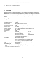
1.1 Description
There are two options for AM3440 FXS/FXO plug-in card: 12FXS/FXO and 24 FXS/FXO. 12FXS/FXO is
designed for the single slot, and 24 FXS/FXO is designed for dual slots of Loop-AM3440 series. They both
allow voice frequency interfaces to be multiplexed as a 64 Kbps DS0 signal onto a digital network. FXS card
provides voice Interfaces connect to telephones. FXO provides connections from telephone lines, either from
a central office or from a PBX in RJ11X12 connector (12FXO) or in a single RJ21X (Telco 50pin) connector
(24FXO).
1.2 Specification
Voice Card (12FXS,12FXO, 24FXS, 24FXO)
12 FXS/FXO Connector
Twelve RJ11
24 FXS/FXO Connector
One RJ21X
Alarm Conditioning
CGA busy after 2.5 seconds of LOS, LOF
Encoding
A-law or μ-law, user selectable together for all
AC Impedance
Balanced 600 or 900 ohms (selectable together for all)
Longitudinal Conversion Loss
> 46dB
Cross talk measure
Max -70dBm0
Gain Adjustment
-21 to +10 dB / 0.1dB step transmit & receive
Signal/ Distortion
> 25dB with 1004 Hz, 0dBm input
Frequency Response
- 0.25 to -1 dB from 300 to 3400 Hz, coincide with ITU-T G.712
Idle Channel Noise
Max. –65 dBm0p
Variation of Gain
±0.5dB
FXO
Ringing REN
0.5B (AC)
Detectable Ringing
25 Vrms
Loop Resistance
≤ 1800 Ω
DC Impedance (ON-HOOK)
> 1M Ω
DC Impedance (OFF-HOOK)
235 Ω @ 25mA feed
90 Ω @ 100mA feed
FXS Loop Feed
-48Vdc or -24Vdc with 25mA current limit per port
Jumper Selectable: 25mA, 30mA, 35mA
FXS signalling
Normal / Automatic Ring down
FXS Ringing
1 REN at 5K meters per port
16.7Hz, 20Hz, 25Hz, 50Hz, user selectable for all ports
38 to 85 Vrms (sine wave), 76 Vrms for default Ring Voltage
2 sec on 4 sec off, or 1 sec on 2 sec off optional for PLAR
Signaling
Loop Start, DTMF, pulse, PLAR, Battery Reverse
Optional Signaling (for special
Ground Start, Metering pulse (12 KHz, 16 KHz), and P( in PLAR mode, PLAR signalling bits
order)
are programmable.
Signaling Bit A,B,C,D
Programable bit
z
All in-band signaling tones are carried transparently by the digitizing process.
z
Customer is responsible for in-band signaling compatibility between a telephone and a switch, or between a PBX and a
switch.
z
-24Vdc power is for FXS PCB version L and up
1
CHAPTER 1 PRODUCT INTRODUCTION
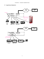
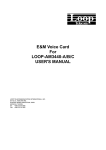
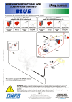
1.3
Application Illustration
Digital
C.O.
WAN
PLAR ON
E1 / T1
Loop-AM3440
FXS Card
Metering Pulse
(12KHz/ 16KHz)
CO
switch
Support Telephones
GND-start
(Caller ID)
Hot
line
Pay Phone
Modem
WAN
Loop-AM3440
E1 / T1
FXO
Pulse Detect
12KHz/ 16KHz
CO
switch
Support pay
phone
Co switch
PABX
Support
GND-start
2
Digital
C.O.
CHAPTER 2 INSTALLATION
2 INSTALLATION
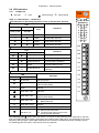
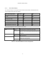
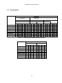
2.1 Default Configuration
Item
A/ µ Law
Impedance
Tx Gain
Rx Gain
PLAR Ring Cadence
Ring Frequency
Metering Pulse
Metering Pulse
Frequency
Metering Level
PLAR
Option/ Range
A Law, µ Law
600 ohm, 900 ohm
-21 to +10 dB
-21 to +10 dB
2" on 4" off, 1" on 2" off
16.7, 20, 25, 50 Hz
On, Off
12 KHz, 16 KHz
Default
A Law
600 ohm
-3 dB
-3 dB
2" on 4" off
20 Hz
Off
16 KHz
1Vrms, 2.4Vrms
On, Off
2.4Vrms
Off
Table 2-1 FXS Plug-in card Default Configuration
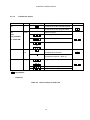
Item
A/ µ Law
Impedance
Tx Gain
Rx Gain
Trunk Condition
Line Polarity
Metering Pulse
Frequency
Metering Pulse
Detect Mode
Metering Pulse
Decode Level
Option/ Range
A Law, µ Law
600 ohm, 900 ohm
-21 to +10 dB
-21 to +10 dB
On hook, Off hook
Normal, Reverse
12 KHz, 16 KHz
Default
A Law
600 ohm
-3 dB
-3 dB
On hook
Normal
16 KHz
Normal, Packet
Normal
-19 to -47 dBm
-27 dBm
Table 2-2 FXO Plug-in card Default Configuration
3
CHAPTER 2 INSTALLATION
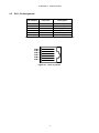
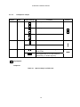
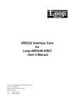
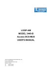
2.2
RJ11 Pin Assignment
Pin Number
1
2
3
4
5
6
Table 2-3
Line Color
Description
Red
Green
Unassigned
Unassigned
Ring lead
Tip lead
Unassigned
Unassigned
RJ11 Connector Pin Assignment - FXS/ FXO Card
PIN 6
PIN 5
PIN 4
PIN 3
PIN 2
PIN 1
Figure 2-1 RJ11 Connector
4
CHAPTER 2 INSTALLATION
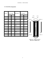
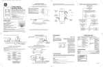
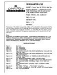
2.3 RJ21X Pin Assignment
LEFT Card RJ21X PIN
RIGHT Card
RJ21X PIN
Line No
Line Number
(teleco 50PIN)
(teleco 50 PIN)
Ring
Tip
Ring
Tip
Line 1
1
26
Line 1
13
38
Line 2
2
27
Line 2
14
39
Line 3
3
28
Line 3
15
40
Line 4
4
29
Line 4
16
41
Line 5
5
30
Line 5
17
42
Line 6
6
31
Line 6
18
43
Line 7
7
32
Line 7
19
44
Line 8
8
33
Line 8
20
45
Line 9
9
34
Line 9
21
46
Line 10
10
35
Line 10
22
47
Line 11
11
36
Line 11
23
48
Line 12
12
37
Line 12
24
49
(L2)
(L1)
Ring
TIP
PIN 1
PIN 26
PIN 25
PIN 50
Table 2-4 RJ21X Connector Pin Assignment – 24 FXS/ FXO Card
Figure 2-2 RJ21X Connector –
FXS, FXO, and MAG Cards
5
CHAPTER 2 INSTALLATION
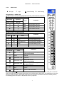
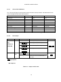
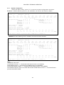
2.4 LED Indication
2.4.1
12 FXS Card
z
{ Light
No Light
☼
Show Flashing
Ì
Fast Flashing
A-law
U-law
Table 3- 1 LED Indication – 12FXS Card
LED Indication for Encoding/ Impedance: A-law, µ-law/ 600 ohm, 900 ohm
LED
Encoding
FXS
Impedance
Indication
Color
A-law, µ-law
600, 900
{
{
Green
A-law mode, 600 ohm
{
z
Green
A-law mode, 900 ohm
z
z
{
Green
µ-law mode, 600 ohm
z
Green
µ-law mode, 900 ohm
LED Indication for Metering Pulse
LED
Indication
Color
METERING PLS
12K
6
5
4
3
2
1
L11
16K
z
Off
Metering Pulse is OFF
{
Ì
z
z
z
Green
12 KHz metering pulse is ON
L9
Green flash 8 Hz
12 KHz pulse is operating
L8
z
{
Green
16 KHz metering is ON
z
Ì
Green flash 8 Hz
16 KHz metering pulse is
operating
LED
L1 to L12
Indication
Color
L10
L7
L6
L5
L4
z
All LED off
No input power
z
Off
Tip Lead Open,
[Ground Start Mode]
{
Green
Normal
☼
Green flash 1 Hz
Off Hook
☼
Green flash 4 Hz
Ring Lead Ground,
[Ground Start Mode]
Ì
Green flash 8 Hz
1. Metering Pulse [Metering Pulse Mode]
2. Battery Reverse
Ì
Green flash 16 Hz
Ringing
{
Red
Alarm
Red flash 1 Hz
(1) Alarm at Off Hook status
(2) The other party hangs up first on the
phone at PLAR ON status
☼
16K
12
11
10
9
8
7
L12
12K
LED Indication for Line 1 to Line 12
600
900
L3
L2
L1
Fast Flashing light Ì: When either one of the L1~L12 port is under metering pulse mode (that is, the LED
light of that particular port is flashing green light), the metering pulse LED (12K or 16K, depending on its pulse
frequency) will also flash in green light at the same time. But if the LED flashes because of battery reverse,
the metering pulse LED (12K or 16K) will not have any response.
6
CHAPTER 2 INSTALLATION
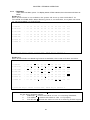
2.4.2
z
12FXO Card
{ Light
No Light
☼
Show Flashing
Ì
Fast Flashing
LED Indication - 12FXO Card
LED Indication for Encoding/ Impedance: A-law, µ-law/ 600 ohm, 900 ohm
LED
Encoding
Impedance
Indication
Color
A-law, µ-law
600, 900
{
{
Green
A-law mode, 600 ohm
{
z
Green
A-law mode, 900 ohm
z
z
{
Green
µ-law mode, 600 ohm
z
Green
µ-law mode, 900 ohm
LED Indication for Metering Pulse
A-law
U-law
600
900
METERING PLS
12K
6
5
4
3
2
1
16K
12
11
10
9
8
7
L12
LED
Indication
12K
16K
z
Off
Metering Pulse is OFF
{
Ì
z
z
z
Green
12 KHz metering is ON
Green flash 8 Hz
12 KHz pulse is operating
z
z
{
Ì
Green
16 KHz metering is ON
Green flash 8 Hz
16 KHz pulse is operating
Color
LED Indication for Line 1 to Line 12
LED
L1 to L12
FXO
Indication
Color
L11
L10
L9
L8
L7
L6
L5
z
Off
Tip Lead Open or Line Empty,
[Ground Start Mode]
{
Green
Normal
☼
Green flash 1 Hz
Off Hook
☼
Green flash 4 Hz
Ring Lead Ground,
[Ground Start Mode]
L2
Ì
Green flash 8 Hz
1. Metering Pulse [Metering Pulse Mode]
2. Battery Reverse
L1
Ì
Green flash 16 Hz
Ringing
{
Red
Alarm
☼
Red flash 1 Hz
Alarm at Off Hook status
L4
L3
Fast Flashing light Ì: When either one of the L1~L12 port is under metering pulse mode (that is, the LED
light of that particular port is flashing green light), the metering pulse LED (12K or 16K, depending on its pulse
frequency) will also flash in green light at the same time. But if the LED flashes because of battery reverse,
the metering pulse LED (12K or 16K) will not have any response.
7
CHAPTER 2 INSTALLATION
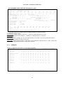
Table 3- 2 LED Indication – 24FXS Plug-in card
z
{ Light
No Light
☼
Show Flashing
Ì
Fast Flashing
LEFT
LED Indication for Encoding/ Impedance: A-law, µ-law/ 600 ohm, 900 ohm
LED
FXS
Encoding Impedance
A-law
µ-law
Indication
Color
600
900
A-law
U-law
FXS
600
900
METERING PLS
{
{
Green
A-law mode, 600 ohm
{
z
Green
A-law mode, 900 ohm
z
z
RIGHT
{
Green
µ-law mode, 600 ohm
z
Green
µ-law mode, 900 ohm
12K
16K
A-law
U-law
METERING PLS
12K
16K
6
12
6
12
5
11
5
11
4
10
4
10
3
9
3
9
2
8
2
8
1
7
1
7
LED Indication for LEFT /RIGHT Side Plug-in card Metering Pulse
LED
16K
z
Off
Metering Pulse is OFF
{
Ì
z
z
z
Green
12 KHz metering is ON
Green flash 8 Hz
12 KHz pulse is operating
z
z
{
Ì
Green
16 KHz metering is ON
Green flash 8 Hz
16 KHz pulse is operating
Color
LED Indication for LEFT /RIGHT Side Plug-in card from Line 1 to Line 12
LED
L1 to L12
RING
Indication
12K
Indication
Color
z
All LED off
No input power
z
Off
Tip Lead Open,
[Ground Start Mode]
{
Green
Normal
☼
Green flash 1 Hz
Off Hook
☼
Green flash 4 Hz
Ring Lead Ground,
[Ground Start Mode]
Ì
Green flash 8 Hz
1. Metering Pulse [Metering Pulse Mode]
2. Battery Reverse
Ì
Green flash 32 Hz
Ringing
{
Red
Alarm
☼
Red flash 1 Hz
3. Alarm at Off Hook status
The other party hangs up first on the
phone at PLAR ON status
TIP
1
L
E
F
T
12
1
R
I
G
H
T
12
Fast Flashing light Ì: When either one of the 1~12 port is under metering pulse mode (that is, the LED light
of that particular port is flashing green light), the metering pulse LED (12K or 16K, depending on its pulse
frequency) will also flash in green light at the same time. But if the LED flashes because of battery reverse,
the metering pulse LED (12K or 16K) will not have any response.
8
600
900
CHAPTER 2 INSTALLATION
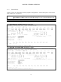
Table 3- 3 LED Indication - 24FXO Plug-in card
z
{ Light
No Light
☼
Ì
Show Flashing
Fast Flashing
LEFT
LED Indication for Encoding/ Impedance: A-law, µ-law/ 600 ohm, 900 ohm
RIGHT
FXO
FXO
LED
A-law
U-law
Encoding Impedance
Indication
Color
600
900
{
{
Green
A-law mode, 600 ohm
{
z
Green
A-law mode, 900 ohm
{
Green
µ-law mode, 600 ohm
z
Green
µ-law mode, 900 ohm
z
z
METERING PLS
12K
A-law
µ-law
600
900
16K
A-law
U-law
METERING PLS
12K
16K
6
12
6
12
5
11
5
11
4
10
4
10
3
9
3
9
2
8
2
8
1
7
1
7
RING
TIP
LED Indication for LEFT /RIGHT Side Plug-in card Metering Pulse
LED
Indication
12K
16K
Color
z
Off
Metering Pulse is OFF
{
Ì
z
z
z
Green
12 KHz metering is ON
Green flash 8 Hz
12 KHz pulse is operating
z
z
{
Ì
Green
16 KHz metering is ON
Green flash 8 Hz
16 KHz pulse is operating
1
LED Indication for LEFT /RIGHT Side Plug-in card from Line 1 to Line 12
LED
L1 to L12
L
E
F
T
12
1
R
I
G
H
T
12
Indication
Color
z
Off
Tip Lead Open or Line Empty, [Ground Start
Mode]
{
Green
Normal
☼
Green flash 1 Hz
Off Hook
☼
Green flash 4 Hz
Ring Lead Ground,
[Ground Start Mode]
Ì
Green flash 8 Hz
1. Metering Pulse [Metering Pulse Mode]
2. Battery Reverse
Ì
Green flash 32 Hz
Ringing
{
Red
Alarm
☼
Red flash 1 Hz
Alarm at Off Hook status
600
900
Fast Flashing light Ì: When either one of the 1~12 port is under metering pulse mode (that is, the LED light
of that particular port is flashing green light), the metering pulse LED (12K or 16K, depending on its pulse
frequency) will also flash in green light at the same time. But if the LED flashes because of battery reverse,
the metering pulse LED (12K or 16K) will not have any response.
9
CHAPTER 2 INSTALLATION
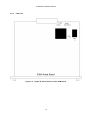
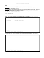
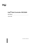
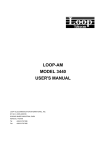
2.5 Jumper & LED Application
2.5.1
FXS Card
Figure 2-3 Jumper & LED locations on FXS PCB Board
10
CHAPTER 2 INSTALLATION
2.5.1.1
LED on FXS PCB Board
LD1, LD3 are LED lights for showing each steps under device boot procedure. See below table for the
color of the lights and the status they represent.
Steps under boot procedure
Time (sec)
LD1
LD3
Card plug-in
0
Red
Red
Run flash
1
Dark
Dark
Test RAM ok, check bank
4
Red
Dark
Load firmware to RAM
15
Dark
Red
Enter firmware
17
Red
Red
Load FPGA
27
Flash Red
Flash Red
FPGA ok, running
32
Dark
Dark
RAM or Flash fail
32
Red
-
FPGA or NW 1034 or FX 461 fail
32
-
Red
The function and application of other LED lights are listed below:
LED
FUSE
Color
Description
Normal
The input power of 12 FXS card is under 80Vac
Break
The input power of 12 FXS card is over 80Vac. The LED
lights (L1~L12) on the front panel will also shut down at the
same time.
LD2
LD4
Red
Ring Generator on
Off
Ring Generator off
Green
Input power under normal condition:-48V or -24V.
FUSE under normal operation
Off
FUSE breaks, no input power
Table 2-5 LED on FXS PCB Board: Function and Application
11
CHAPTER 2 INSTALLATION
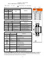
2.5.1.2
FXS Normal Jumper
Number
Name
JP1
P
Jumper Settings
Function
PLAR bit set to OFF-Hook llll, Ring llll
PLAR bit set to user programmable
JP2
Normal (12FXS)
Model
Note:
Metering pulse (12FXS-M)
Only available
Ground Start (12FXS-GS)
for 12FXS-GM
Metering + Ground (12FXS-GM)
or
J3
BANK
Enable flash download to work under
SW
its default firmware bank
Switch the flash download working
firmware bank (Bank 1, Bank 2)
J9
Ringer
Ringer Output Voltage: 76 VAC
or
Ringer Output Voltage: 64 VAC
Ringer Output Voltage: 86 VAC
: Unjumpered
: Jumpered
Table 2-6 Normal Jumper on FXS Card
12
Default
CHAPTER 2 INSTALLATION
2.5.1.3
FXS Special Jumper
Number
Name
J8
S1
Jumper Settings
Function
FXS output line current: 25mA
FXS output line current: 30mA
FXS output line current: 35mA
J7
S4
Disable alarm tone
Enable alarm tone
J6
S5
Set ring generator to automatic (power
saver) mode
Set ring generator to non-stop mode for
special use (i.e. double ring tone)
: Unjumpered
: Jumpered
Table 2-7 Special Jumper on FXS Card
13
Default
CHAPTER 2 INSTALLATION
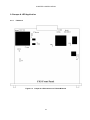
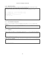
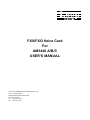
2.5.2
FXO Card
Figure 2-4 Jumper & LED locations on FXO PCB Board
14
CHAPTER 2 INSTALLATION
2.5.2.1
LED on FXO PCB Board
LD1, LD2 are LED lights for showing each steps under device boot procedure. See below table for the
color of the lights and the status they represent.
Steps under boot procedure
Time (sec)
LD1
LD2
Card plug-in
0
Red
Red
Run flash
1
Dark
Dark
Test RAM ok, check bank
4
Red
Dark
Load firmware to RAM
15
Dark
Red
Enter firmware
17
Red
Red
Load FPGA
27
Flash Red
Flash Red
FPGA ok, running
32
Dark
Dark
RAM or Flash fail
32
Red
-
FPGA or NW 1034 or FX 461 fail
32
-
Red
Table 2-8 LED on FXO PCB Board: Function and Application
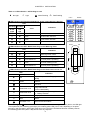
2.5.2.2
FXO Jumper
Number
Name
J9
Model
Jumper Settings
Function
Normal (12FXO)
Only
Metering pulse (12FXO-M)
available for
Ground Start (12FXO-GS)
12FXO-GM
Metering + Ground (12FXO-GM)
or
J3
BANK
SW
Bank switch unavailable
Switch the current firmware bank to
the other
: Unjumpered
: Jumpered
Table 2-9 Jumper on FXO Card
15
Default
CHAPTER 2 INSTALLATION
2.6
Signaling Bits
FXS/FXS-P
PLAR ON
PLAR OFF
FXS/FXS-P
FXS
TX
On hook
Off hook
No ring
Ring on
Battery Reverse
Metering Pulse
Tip lead open
Ring lead GND
OOS-Alarm
A
0
1
0
B C D A
1 0 1
1 0 1
1
0
0
0
1
0 0 1
*
B C D A
0
1
* * *
0 * *
1 0 0
1 0 0
1 1 1
*
*
FXS-P
RX
B C D A
1 0 1
1 1 1
0
1
*
*
TX
B C D A
0
1
* * *
1 1 1
*
*
B C D A
1 0 1
1 0 1
1
0
*
*
Table 2-10 Signaling Bits (Default Setting) - FXS Card
FXO
TX
A
B
C
RX
D
A
0
1
B
*
1
C
*
*
D
*
*
On hook
Off hook
No ring
0
1
0
1
Ring On
0
0
0
1
Battery Reverse
0
1
0
0
Metering Pulse
0
1
0
0
Tip Lead open
1
1
1
1
Ring lead GND
0
0
0
1
OOS-Alarm
*
*
*
*
Table 2-11 Signaling Bits (Default Setting) -FXO Card
16
RX
B C D
*
0
*
*
*
*
*
*
*
CHAPTER 3 TERMINAL OPERATION
3 TERMINAL OPERATION
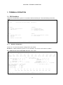
3.1 FXS Sub-Menu
Under the Controller Menu, press “U” to choose a slot for the FXS port. Then the following screen will
show.
SLOT 12 FX S
=== Por t M enu ===
Vers ion
: SW V3 .01. 01 05/ 07/2 009 ,
1 6:42 :00 05 /19/ 200 9
HW V er. L
[DIS PLA Y]
C -> Sy ste m Co nfi gur atio n
I -> FX S S tatu s
[SET UP]
S -> Sy ste m Se tup
T -> Di agn osti c T est
G -> Up gra de F irm war e
[LOG ]
U -> Ch oos e Ot her Sl ot
F -> Lo g O ff
O -> Lo g O n
E -> Re tur n to Ma in Menu
[MIS C]
Y -> Un it Load De fau lt C onf ig
Z -> Un it Rese t
>>SP ACE ba r to re fre sh o r e nte r a com man d == =>
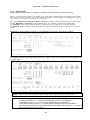
3.1.1
System Configuration
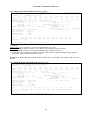
Press "C" to view the system configuration as below.
E X AM P LE 1: When Metering Pulse is not available, the screen will show as below.
For FXS Normal mode PCB H/W Version F or over:
SLOT 12 FX S
=== S yste m C onf igur ati on ===
1 1:35 :27 11 /11/ 200 8
A/u- Law : A
L1
TxGa in: -3 .0
RxGa in: -3 .0
Imp e danc e : 60 0 oh m
L2
L3
L4
L5
L6
L7
L8
L9
L10
L11
L12
-3 .0
-3.0
-3. 0
-3.0
-3 .0
-3 .0
-3.0
-3. 0
-3.0
-3 .0
-3 .0
-3 .0
-3.0
-3. 0
-3.0
-3 .0
-3 .0
-3.0
-3. 0
-3.0
-3 .0
-3 .0
( -2 1 ~ +10 in dB )
Tx S ign ali ng B it
A
B
C
D
Rx S i gnal ing Bi t
A
B
C
D
ON HOO K : 0
1
0
1
RIN G ON : 0
0
*
*
OFF HOO K : 1
1
0
1
BATT -REV : 0
1
0
0
RIN G-GN D : ( NA )
OOS- A LARM : *
*
*
*
PLAR OF F HOO K : 1
1
1
1 ( fixe d)
TIP- OPEN : ( N A )
PLAR RI N G ON : 1
1
1
1 (f ixed )
PLAR Ri ng Cade nce : 2"ON ,4" OFF
( * fo r d on' t ca re )
Ring
Fre q uenc y
: 20
Hz
Mete rin g P ulse
: ( NA )
Mete rin g F req.
: ( NA )
Mete rin g L evel
: ( NA )
PLAR
L1
OFF
L2
O FF
L3
OFF
L4
O FF
L5
OFF
L6
O FF
L7
OFF
L8
O FF
L9
OFF
L1 0
O FF
<< E SC key to ret urn to pre vio us m enu , S PACE ba r t o re fre sh >>
17
L11
OFF
L 12
O FF
CHAPTER 3 TERMINAL OPERATION
For FXS-P mode PCB H/W Version F or over:
SLOT 12 FX S
=== Sys tem Set up ===
10 :07 :51 11/ 11/ 200 8
ARRO W K EYS : CU RSO R M OVE, TA B: ROLL OP TIO NS
A/u- Law : A
Imp e danc e : 60 0 oh m
L1
L2
L3
L4
L5
L6
L7
L8
L9
L10
L11
L12
TxGa in: -3 .0
-3 .0
-3.0
-3. 0
-3.0
-3 .0
-3 .0
-3.0
-3. 0
-3.0
-3 .0
-3 .0
RxGa in: -3 .0
-3 .0
-3.0
-3. 0
-3.0
-3 .0
-3 .0
-3.0
-3. 0
-3.0
-3 .0
-3 .0
ALL Tx/ Rx Gain = L1 : NO
( - 2 1 ~ +10 in dB )
Tx S ign ali ng B it
A
B
C
D
Rx S i gnal ing Bi t
A
B
C
D
ON HOO K : 0
1
0
1
RIN G ON : 0
0
*
*
OFF HOO K : 1
1
0
1
BAT T-RE V & PL S ON : 0
1
0
0
RIN G-GN D : ( NA )
OO S-A LARM : *
* *
*
PLAR OF F HOO K : 1
1
0
1 ( =OFF HO OK)
TIP- OPEN : ( N A )
PLAR RI N G ON : 0
0
*
* (= RING ON )
PLAR Ri ng Cade nce : 2"ON ,4" OFF
( * fo r d on' t ca re )
Ring
Fre q uenc y
: 20
Hz
Mete rin g P ulse
: (NA)
Mete rin g F req.
: (NA)
Mete rin g L evel
: (NA)
PLAR
L1
L2
OFF
O FF
ALL PLA R = L1 : N O
L3
OFF
L4
O FF
L5
OFF
L6
O FF
L7
OFF
L8
O FF
L9
OFF
L1 0
O FF
L11
OFF
L 12
O FF
<< P res s E SC k ey to retu rn to prev iou s m enu >>
Note:
1. FXS-P
New mode: put a jumper to JP1 for H/W Version H or over
Old mode: add a R367 resister in the back of the PCB for H/W Version
2. FXS-P mode PLAR bit can programmable when PLAR turns on
3. Regarding US ring back signaling for the FXS Card, PLAR generates a 440/480Hz
ring-back tone (H/W version H or over).
E X AM P LE 2: When Metering Pulse and Ground start is available, the screen will show as
below.
For FXS-GM mode PCB H/W Version H or over:
SLOT 12 FXS
=== System Configuration ===
10:07:51 11/11/2008
ARRO W K EYS : CU RSO R M OVE, TA B: ROLL OP TIO NS
A/u- Law : A
Imp e danc e : 60 0 oh m
L1
L2
L3
L4
L5
L6
L7
L8
L9
L10
L11
L12
TxGa in: -3 .0
-3 .0
-3.0
-3. 0
-3.0
-3 .0
-3 .0
-3.0
-3. 0
-3.0
-3 .0
-3 .0
RxGa in: -3 .0
-3 .0
-3.0
-3. 0
-3.0
-3 .0
-3 .0
-3.0
-3. 0
-3.0
-3 .0
-3 .0
ALL Tx/ Rx Gain = L1 : NO
( - 2 1 ~ +10 in dB )
Tx S ign ali ng B it
A
B
C
D
Rx S i gnal ing Bi t
A
B
C
D
ON HOO K : 0
1
0
1
RIN G ON : 0
0
*
*
OFF HOO K : 1
1
0
1
BAT T-RE V & PL S ON : 0
1
0
0
RIN G-GN D : 0
0
0
1
OOS -A LARM : ( N A )
PLAR OF F HOO K : 1
1
1
1 ( fixe d)
TI P- OPEN : 1
1
1
1
PLAR RI N G ON : 1
1
1
1 (f ixed )
PLAR Ri ng Cade nce : 2"ON ,4" OFF
( * fo r d on' t ca re )
Ring
Fre q uenc y
: 20
Hz
Mete rin g P ulse
: OFF
Mete rin g F req.
:
16 K Hz
Mete rin g L evel
:
2.4V rms
PLAR
L1
L2
OFF
O FF
ALL PLA R = L1 : N O
L3
OFF
L4
O FF
L5
OFF
L6
O FF
L7
OFF
<< P res s E SC k ey to retu rn to prev iou s m enu >>
18
L8
O FF
L9
OFF
L1 0
O FF
L11
OFF
L 12
O FF
CHAPTER 3 TERMINAL OPERATION
For FXS-GMP mode PCB H/W Version H or over:
SLOT 12 FX S
=== Sys tem Set up ===
10 :07 :51 11/ 11/ 200 8
ARRO W K EYS : CU RSO R M OVE, TA B: ROLL OP TIO NS
A/u- Law : A
Imp e danc e : 60 0 oh m
L1
L2
L3
L4
L5
L6
L7
L8
L9
L10
L11
L12
TxGa in: -3 .0
-3 .0
-3.0
-3. 0
-3.0
-3 .0
-3 .0
-3.0
-3. 0
-3.0
-3 .0
-3 .0
RxGa in: -3 .0
-3 .0
-3.0
-3. 0
-3.0
-3 .0
-3 .0
-3.0
-3. 0
-3.0
-3 .0
-3 .0
ALL Tx/ Rx Gain = L1 : NO
( - 2 1 ~ +10 in dB )
Tx S ign ali ng B it
A
B
C
D
Rx S i gnal ing Bi t
A
B
C
D
ON HOO K : 0
1
0
1
RIN G ON : 0
0
*
*
OFF HOO K : 1
1
0
1
BAT T-RE V & PL S ON : 0
1
0
0
RIN G-GN D : 0
0
0
1
OO S-A LARM : ( N A )
PLAR OF F HOO K : 1
1
0
1 ( =OFF HO OK)
TIP- OPEN : 1
1
1
1
PLAR RI N G ON : 0
0
*
* (= RING ON )
PLAR Ri ng Cade nce : 2"ON ,4" OFF
( * fo r d on' t ca re )
Ring
Fre q uenc y
: 20
Hz
Mete rin g P ulse
: OFF
Mete rin g F req.
:
16 K Hz
Mete rin g L evel
:
2.4V rms
PLAR
L1
L2
OFF
O FF
ALL PLA R = L1 : N O
L3
OFF
L4
O FF
L5
OFF
L6
O FF
L7
OFF
L8
O FF
L9
OFF
L1 0
L11
L 12
O FF
OFF
O FF
<< P res s E SC k ey to retu rn to prev iou s m enu >>
Note:
1. FXS-GM mode with metering pulse 12KHz/16KHz and Ground start.
2. Metering Pulse Level
New mode: support level 2.4Vrms or 1 Vrms for H/W Version H or over.
Old mode: support level 0dBm or –24dBm for H/W Version F or below.
3. FXS-GMP
New mode: put a jumper for JP1 for H/W Version H or over. Than the PLAR bit can be
programmable when PLAR is turned on.
Old mode: add a R367 resister in the back of the PCB for H/W Version F. Then, the PLAR
bit can be programmable when PLAR is turned on.
3.1.2
FXS Status
Press "I" from the Port Menu to view the FXS status.
SLOT 12 FX S
=== FXS St atus == =
1 1:38 :07 11 /11/ 200 8
1.O FF HOO K
:
L1
L2
L3
L4
L5
L6
L7
L8
L9
L1 0
L 11
L1 2
2.M ETE RIN G PU LSE
:
NA
NA
NA
NA
NA
NA
NA
NA
NA
NA
NA
NA
3.T IP- OPE N
:
NA
NA
NA
NA
NA
NA
NA
NA
NA
NA
NA
NA
4.R ING -GN D
:
NA
NA
NA
NA
NA
NA
NA
NA
NA
NA
NA
NA
5.P LAR ON
:
L1
L2
L3
L4
L5
L6
L7
L8
L9
L1 0
L 11
L1 2
6.R ING ING
:
L1
L2
L3
L4
L5
L6
L7
L8
L9
L1 0
L 11
L1 2
7.A LAR M O N
:
L1
L2
L3
L4
L5
L6
L7
L8
L9
L1 0
L 11
L1 2
<< p res s E SC k ey to retu rn to main me nu, SPA CE key to ref res h >>
19
CHAPTER 3 TERMINAL OPERATION
3.1.3
System Setup
Press "S" from the Port Menu to setup system configuration. Use arrow keys to move cursor
and TAB key to roll options.
NOTE1:
ALL PLAR = L1: YES, means that PLAR setting of L2 to L12 are same as L1.
ALL PLAR = L1: NO, means that PLAR setting of L2 to L12 are different from
L1.
The option, OOS-ALARM, is only available for new E1 and new T1 interfaces.
NOTE2:
E X AM P LE 1: When Metering Pulse is not available, the screen will show as below.
For FXS-GM mode PCB H/W Version H or over:
SLOT 12 FX S
=== S yst em Setu p = ==
16:51 :46 11 /11/ 200 8
ARRO W K EYS : CU RSO R M OVE, TA B/` : RO LL UP/ DOWN OP TIO NS
A/u- Law : A
Imp e danc e : 60 0 oh m
L1
L2
L3
L4
L5
L6
L7
L8
L9
L10
L11
L12
TxGa in: -3 .0
-3 .0
-3.0
-3. 0
-3.0
-3 .0
-3 .0
-3.0
-3. 0
-3.0
- 3.0
- 3.0
RxGa in: -3 .0
-3 .0
-3.0
-3. 0
-3.0
-3 .0
-3 .0
-3.0
-3. 0
-3.0
- 3.0
- 3.0
ALL Tx/ Rx Gain = L1 : NO
( - 2 1 ~ +10 in dB )
Tx S ign ali ng B it
A
B
C
D
Rx S i gnal ing Bi t
A
B
C
D
ON HOO K : 0
1
0
1
RIN G ON : 0
0
*
*
OFF HOO K : 1
1
0
1
BATT -REV : 0
1
0
0
RIN G-GN D : ( NA )
OOS- A LARM : *
*
*
*
PLAR OF F HOO K : 1
1
1
1 ( fixe d)
TIP- OPEN : ( N A )
PLAR RI N G ON : 1
1
1
1 (f ixed )
PLAR Ri ng Cade nce : 2"ON ,4" OFF
( * fo r d on' t ca re )
Ring
Fre q uenc y
: 20
Hz
Mete rin g P ulse
: ( NA )
Mete rin g F req.
: ( NA )
Mete rin g L evel
: ( NA )
PLAR
L1
L2
OFF
O FF
ALL PLA R = L1 : N O
L3
OFF
L4
O FF
L5
OFF
L6
O FF
L7
OFF
L8
O FF
L9
OFF
L1 0
O FF
L11
OFF
L 12
O FF
<< P res s E SC k ey to retu rn to prev iou s m enu >>
For FXS-GMP mode PCB H/W Version H or over:
SLOT 12 FX S
=== S yst em Setu p = ==
16:51 :46 11 /11/ 200 8
ARRO W K EYS : CU RSO R M OVE, TA B/` : RO LL UP/ DOWN OP TIO NS
A/u- Law : A
Imp e danc e : 60 0 oh m
L1
L2
L3
L4
L5
L6
L7
L8
L9
L10
L11
L12
TxGa in: -3 .0
-3 .0
-3.0
-3. 0
-3.0
-3 .0
-3 .0
-3.0
-3. 0
-3.0
- 3.0
- 3.0
RxGa in: -3 .0
-3 .0
-3.0
-3. 0
-3.0
-3 .0
-3 .0
-3.0
-3. 0
-3.0
- 3.0
- 3.0
ALL Tx/ Rx Gain = L1 : NO
( - 2 1 ~ +10 in dB )
Tx S ign ali ng B it
A
B
C
D
Rx S i gnal ing Bi t
A
B
C
D
ON HOO K : 0
1
0
1
RIN G ON : 0
0
*
*
OFF HOO K : 1
1
0
1
BATT -REV : 0
1
0
0
RIN G-GN D : ( NA )
OOS- A LARM : (NA )
PLAR OF F HOO K : 1
1
1
1 ( =OFF HO OK)
TIP- OPE N : 1 1 1 1
PLAR RI N G ON :
0 0 * *
(=R ING ON)
PLAR Ri ng Cade nce : 2"ON ,4" OFF
( * fo r d on' t ca re )
Ring
Fre q uenc y
: 20
Hz
Mete rin g P ulse
: OFF
Mete rin g F req.
: 16 K HZ
Mete rin g L evel
: 2.4 Vrm s
PLAR
L1
L2
OFF
O FF
ALL PLA R = L1 : N O
L3
OFF
L4
O FF
L5
OFF
L6
O FF
L7
OFF
<< P res s E SC k ey to retu rn to prev iou s m enu >>
20
L8
O FF
L9
OFF
L1 0
O FF
L11
OFF
L 12
O FF
CHAPTER 3 TERMINAL OPERATION
Note:
1. FXS-GM mode with metering pulse 12KHz/16KHz and Ground start.
2. FXS-GMP
New mode: put a jumper to JP1 for H/W Version H or over. Than the PLAR bit can be
programmable when PLAR turns on.
Old mode: add a R367 resister in the back of the PCB for H/W Version F. Then, the PLAR
bit can be programmable when PLAR is turns on.
3. Regarding US ring back signaling for the FXS Card, PLAR generates a 440/480Hz
ring-back tone (H/W version H or over)
3.1.4
Diagnostic Test
Press “T” from the Port Menu to do diagnostic test. Use TAB key to select the desired
option. The current selection will be highlighted by an asterisk (*).
SLOT 12 FX S
== = F XS D iag nos tic Tes t = ==
*1. RIN G T EST
1 1:36 :17 11 /11/ 200 8
2. BAT TER Y RE VER SE TEST
- ST ATU S :
<< p res s E SC k ey to retu rn to main me nu >>
Press ENTER after done the selection. As the following example shows, the system is
doing RING TEST.
SLOT 12 FX S
== = F XS D iag nos tic Tes t = ==
*1. RIN G T EST
- ST ATU S :
2. BAT TER Y RE VER SE TEST
Re mai n 1 2 se con ds.
<< p res s E SC k ey to retu rn to main me nu >>
21
1 1:36 :17 11 /11/ 200 8
CHAPTER 3 TERMINAL OPERATION
3.1.5 Upgrade Firmw are
Press “G” from the Port Menu to start your flash download. Key in the server IP and
firmware file name. Then, press Enter to start the download.
LOOP AM 344 0-A
= == Down loa d F irmw are == =
1 6:42 :24 05 /19/ 200 9
ARRO W K EYS : CU RSO R M OVE, Pl eas e In put : n nn.n nn. nnn .nnn , B ACK SPAC E t o e dit
Bank 1 Fir mwar e V er. : V 3.0 1.0 1 05 /07 /20 09
(Go od)
Bank 2 Fir mwar e V er. : V 3.0 1.0 1 05 /07 /20 09
(Go od)
Work ing Fi rmwa re Ban k: 2
TFTP Se rve r IP
: 0 10. 003 .013 .01 0
Firm war e F ile Nam e
:
<< p res s E SC k ey to retu rn to main me nu >>
3.1.6
Unit Load Default Configuration
Press “Y” from Port Menu to return the default. Then press “Y” or “N” to confirm the
selection.
SLOT 12 FX S
=== Uni t M enu ===
1 1:36 :39 11 /11/ 200 8
Load de fau lt - ar e y ou s ure (Y /N)?
3.1.7
Unit Reset
Press “Z” from Port Menu to reset the unit. Then press “Y” or “N” to confirm the selection.
SLOT 12 FX S
=== Uni t M enu ===
1 1:36 :39 11 /11/ 200 8
Rese t - ar e yo u s ure ? [ Y/N ]
If users enter "Y" to confirm the reset, the system will request users to enter the password,
LOOP, then press ENTER.
SLOT 12 FX S
=== Uni t M enu ===
==>> En ter pas swo rd :
22
1 1:36 :39 11 /11/ 200 8
CHAPTER 3 TERMINAL OPERATION
3.2
FXO Sub-Menu
Under the Controller Menu, press “U” to choose a slot for the FXO port. Then the following screen will
show.
SLOT 1
Vers ion
FXO
=== Por t M enu ===
: SW V2 .01. 01 05/ 07/2 009 ,
[DIS PLA Y]
C -> Sy ste m Co nfi gur atio n
I -> FX O S tatu s
[LOG ]
U -> Ch oos e Ot her Sl ot
F -> Lo g O ff
O -> Lo g O n
E -> Re tur n to Ma in Menu
16:32 :48 05 /19/ 200 9
HW V er. G
[SET UP]
S -> Sy s tem Set up
T -> Di ag nost ic Tes t
G -> Up gra de F irm war e
[MIS C]
Y -> Un it Load De fau lt C onf ig
Z -> Un it Rese t
>>SP ACE ba r to re fre sh o r e nte r a com man d == =>
23
CHAPTER 3 TERMINAL OPERATION
3.2.1
System Configuration
Under the above menu, press "C" to view the system configuration as below.
E X AM P LE 1: When Metering Pulse is not available, the screen will show as below.
SLOT 1 FXO
=== Sy stem Co nfi gura tio n = ==
16:3 2:4 8 0 5/19 /20 09
A/u- Law : A
L1
TxGa in: -3 .0
RxGa in: -3 .0
Imp e danc e : 60 0 oh m
L2
L3
L4
L5
L6
L7
L8
L9
L10
L11
L12
-3 .0
-3.0
-3. 0
-3.0
-3 .0
-3 .0
-3.0
-3. 0
-3.0
-3 .0
-3 .0
-3 .0
-3.0
-3. 0
-3.0
-3 .0
-3 .0
-3.0
-3. 0
-3.0
-3 .0
-3 .0
( -2 1 ~ +10 in dB )
Tx S ign al ing Bit
A
B
C
D
Rx S ign a ling Bi t
A
B
C
D
RING I NG : 0
0
0
1
OFF-H OOK : 1
1
*
*
NO R I NG : 0
1
0
1
OO S-AL ARM : *
*
*
*
BATT -R EV : 0
1
0
0
RING- GND : 0
0
0
1
PULS E ON : 0
1
0
0
( * for d on't ca re )
TIP- OP EN : 1
1
1
1
Trun k C ond itio n : ON -HOO K
Line Po lar ity
: NO RMAL
Mete rin g P ulse Fr equ ency
: 1 6 KH z
Mete rin g P ulse De tec t Mo de : N ORMA L
Mini mum Pu lse Dec ode Lev el ( - 19 ~ -4 7 )
L1
L2
L3
L4
L5
L6
-27
- 27
-2 7
- 27
-2 7
- 27
L7
-2 7
L8
- 27
L9
-2 7
L 10
- 27
L1 1
-2 7
L 12
- 27 ( dBm )
<< E SC key to ret urn to pre vio us m enu , S PACE ba r t o re fre sh >>
EXAMPLE 2: When Metering Pulse is available, the screen will show as below.
SLOT 1 FXO
=== Sy stem Co nfi gura tio n = ==
1 6:32 :48 05 /19/ 200 9
A/u- Law : A
L1
TxGa in: -3 .0
RxGa in: -3 .0
Imp e danc e : 60 0 oh m
L2
L3
L4
L5
L6
L7
L8
L9
L10
L11
L12
-3 .0
-3.0
-3. 0
-3.0
-3 .0
-3 .0
-3.0
-3. 0
-3.0
-3 .0
-3 .0
-3 .0
-3.0
-3. 0
-3.0
-3 .0
-3 .0
-3.0
-3. 0
-3.0
-3 .0
-3 .0
( -2 1 ~ +10 in dB )
Tx S ign al ing Bit
A
B
C
D
Rx S ign a ling Bi t
A
B
C
D
RING I NG : 0
0
0
1
OFF-H OOK : 1
1
*
*
NO R I NG : 0
1
0
1
OO S-AL ARM : *
*
*
*
BATT -R EV : 0
1
0
0
RING- GND : 0
0
0
1
PULS E ON : 0
1
0
0
( * for d on't ca re )
TIP- OP EN : 1
1
1
1
Trun k C ond itio n : ON -HOO K
Line Po lar ity
: NO RMAL
Mete rin g P ulse Fr equ ency
: 1 6 KH z
Mete rin g P ulse De tec t Mo de : N ORMA L
Mini mum Pu lse Dec ode Lev el ( - 19 ~ -4 7 )
L1
L2
L3
L4
L5
L6
-27
- 27
-2 7
- 27
-2 7
- 27
L7
-2 7
L8
- 27
L9
-2 7
L 10
- 27
L1 1
-2 7
L 12
- 27 ( dBm )
<< E SC key to ret urn to pre vio us m enu , S PACE ba r t o re fre sh >>
Note:
* represents “don’t care”.
If OOS-Alarm is set as ****, it means the OOS alarm function is now disabled.
If Ring-GND is set as ****, it means the ring-GND function is now disabled.
If OFF-HOOK status is set as ****, it means the OFF-HOOK function is now disabled.
If the software version is V2.01.03 or after and the OFF-HOOK status is set as ****, it means all twelve
ports are set as OFF-HOOK.
24
CHAPTER 3 TERMINAL OPERATION
3.2.2
FXO Status
Under FXO Port Menu, press “I” to display status of FXO interface, then the screen will show as
below.
E X AM P LE 1:
When Ground Start is not available, the system will show up “NO AVAILABLE” for
TIP-OPEN and RING-GND. When Metering Pulse is not available, the system will show
up “NO AVAILABLE” for PULSE ON.
SLOT 1 FXO
=== F XO Sta tus ===
16 :32: 48 05/ 19/2 009
1.RI NGI NG
:
L1
L2
L3
L4
L5
L6
L7
L8
L9
L1 0
L 11
L1 2
2.OF F-H OO K
:
L1
L2
L3
L4
L5
L6
L7
L8
L9
L1 0
L 11
L1 2
3.TI P-O PE N
:
L1
L2
L3
L4
L5
L6
L7
L8
L9
L1 0
L 11
L1 2
4.RI NG- GN D
:
L1
L2
L3
L4
L5
L6
L7
L8
L9
L1 0
L 11
L1 2
5.BA TT- RE V
:
L1
L2
L3
L4
L5
L6
L7
L8
L9
L1 0
L 11
L1 2
6.PU LSE O N
:
L1
L2
L3
L4
L5
L6
L7
L8
L9
L1 0
L 11
L1 2
7.AL ARM O N
:
L1
L2
L3
L4
L5
L6
L7
L8
L9
L1 0
L 11
L1 2
<< p res s E SC k ey to retu rn to main me nu, SPA CE key to ref res h >>
E X AM P LE 2:
When Ground Start and Metering Pulse are available, the screen will show as below.
SLOT 1
FXO
=== FXO St atus == =
16:32 :48 05 /19/ 200 9
1.RI NGI NG
:
L1
L2
L3
L4
L5
L6
L7
L8
L9
L1 0
L 11
L1 2
2.OF F-H OO K
:
L1
L2
L3
L4
L5
L6
L7
L8
L9
L1 0
L 11
L1 2
3.TI P-O PE N
:
L1
L2
L3
L4
L5
L6
L7
L8
L9
L1 0
L 11
L1 2
4.RI NG- GN D
:
L1
L2
L3
L4
L5
L6
L7
L8
L9
L1 0
L 11
L1 2
5.BA TT- RE V
:
L1
L2
L3
L4
L5
L6
L7
L8
L9
L1 0
L 11
L1 2
6.PU LSE O N
:
L1
L2
L3
L4
L5
L6
L7
L8
L9
L1 0
L 11
L1 2
7.AL ARM O N
:
L1
L2
L3
L4
L5
L6
L7
L8
L9
L1 0
L 11
L1 2
<< p res s E SC k ey to retu rn to main me nu, SPA CE key to ref res h >>
NOTE1:
L1 means the status of Line1 and L 1 means the status of Line1 is active.
As the above example shows:
1.
RINGING: L 3 means the status of Line 3 is receiving RINGING;
2.
TIP-OPEN: L 1 means the status of Line 1 is Tip-Open;
3.
PULSE ON: L6 means the status of Line 6 is receiving PULSE signal.
25
CHAPTER 3 TERMINAL OPERATION
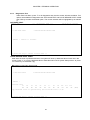
3.2.3 System Setup
Under FXO Port Menu, press “S” to setup FXO system, then the following screen will show up.
When L1’s decode level value is changed, L2’s value will be automatically changed by the system.
Also if L2’s value is changed, L1’s value will be changed too. Same operation is applied for L3 and
L4, L5 and L6, L7 and L8, L9 and L10, L11 and L12
The option Metering Pulse Detect Mode is allowed to select a desired detect mode of pulse. T wo
modes, NORM AL and PACKET , are available here. Use TAB key to switch a desired item.
For NORM AL mode (Tone Follower mode), a logic level for the period of a correct decode.
For P ACKET mode, respond/ de-respond after a cumulative period of tone or no-tone in a preset
period.
E X AM P LE 1: When Metering Pulse is not available, the screen will show as below.
SLOT 1 FXO
=== Sy stem Co nfi gura tio n = ==
16 :32: 48 05/ 19/2 009
ARRO W K EYS : CU RSO R M OVE, TA B: ROLL OP TIO NS
A/u- Law : A
Imp e danc e : 60 0 oh m
L1
L2
L3
L4
L5
L6
L7
L8
L9
L10
L11
L12
TxGa in: -3 .0
-3 .0
-3.0
-3. 0
-3.0
-3 .0
-3 .0
-3.0
-3. 0
-3.0
-3 .0
-3 .0
RxGa in: -3 .0
-3 .0
-3.0
-3. 0
-3.0
-3 .0
-3 .0
-3.0
-3. 0
-3.0
-3 .0
-3 .0
ALL Tx/ Rx Gain = L1 : NO
( - 2 1 ~ +10 in dB )
Tx S ign al ing Bit
A
B
C
D
Rx S ign a ling Bi t
A
B
C
D
RING I NG : 0
0
0
1
OFF-H OOK : 1
1
*
*
NO R I NG : 0
1
0
1
OO S-AL ARM : *
*
*
*
BATT -R EV : 0
1
0
0
RING- GND : 0
0
0
1
PULS E ON : 0
1
0
0
( * for d on't ca re )
TIP- OP EN : 1
1
1
1
Trun k C ond itio n : ON -HOO K
Line Po lar ity
: NO RMAL
<< P res s E SC k ey to retu rn to prev iou s m enu >>
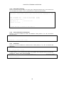
E X AM P LE 2: When Metering Pulse is available, the screen will show as below. This screen
is allowed to setup metering pulse frequency, pulse mode, and minimum pulse decode level
for each line.
SLOT 1 FXO
=== Sy stem Co nfi gura tio n = ==
16 :32: 48 05/ 19/2 009
ARRO W K EYS : CU RSO R M OVtE , T AB: ROL L O PTI ONS
A/u- Law : A
Imp e danc e : 60 0 oh m
L1
L2
L3
L4
L5
L6
L7
L8
L9
L10
L 11
L12
TxGa in: -3 .0
-3 .0
-3.0
-3. 0
-3.0
-3 .0
-3 .0
-3.0
-3. 0
-3.0
-3 .0
-3 .0
RxGa in: -3 .0
-3 .0
-3.0
-3. 0
-3.0
-3 .0
-3 .0
-3.0
-3. 0
-3.0
-3 .0
-3 .0
ALL Tx/ Rx Gain = L1 : NO
( - 2 1 ~ +10 in dB )
Tx S ign al ing Bit
A
B
C
D
Rx S ign a ling Bi t
A
B
C
D
RING I NG : 0
0
0
1
OFF-H OOK : 1
1
*
*
NO R I NG : 0
1
0
1
OO S-AL ARM : *
*
*
*
BATT -R EV : 0
1
0
0
RING- GND : 0
0
0
1
PULS E ON : 0
1
0
0
( * for d on't ca re )
TIP- OP EN : 1
1
1
1
Trun k C ond itio n : ON -HOO K
Line Po lar ity
: NO RMAL
Mete rin g P ulse Fr equ ency
:
Mete rin g P ulse De tec t Mo de :
Mini mum Pu lse Dec ode Lev el (
L1
L2
L3
-27
-27
-27
ALL Lev el= L1 : N O
1 6 KH z
N ORMA L
- 19 ~ -4 7 )
L4
L5
L6
-2 7
-27
-2 7
L7
-27
L8
-2 7
L9
-27
L 10
- 27
L1 1
-2 7
L 12
- 27
(d Bm)
<< P res s E SC k ey to retu rn to prev iou s m enu >>
NOTE1:
NOTE2:
ALL Level= L1 : NO, this option is allowed to copy Line 1’s pulse decode value to all
lines or not. Use TAB key to switch YES (copy to all) or NO (not copy to all).
* represents “don’t care”.
If OOS-Alarm is set as ****, it means the OOS alarm function is now disabled.
If Ring-GND is set as ****, it means the ring-GND function is now disabled.
If OFF-HOOK status is set as ****, it means the OFF-HOOK function is now disabled.
If the software version is V2.01.03 or after and the OFF-HOOK status is set as ****, it means all
twelve ports are set as OFF-HOOK.
26
CHAPTER 3 TERMINAL OPERATION
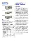
3.2.4
Diagnostics Test
Under FXO Port Menu, press “T” to do diagnostics test, then the screen will show as below. Two
options are available for diagnostics test: OFF-HOOK TEST and PULSE DECODE LEVEL SCAN.
Use TAB key to select the desired option. The current selection will be highlighted by an asterisk
(*).
OFF-HOOK TEST:
SLOT 1 FXO
===
*1.O FF- HO OK T EST
- ST ATU S :
D iagn ost ic Test == =
16 :32: 48 05/ 19/2 009
2.PU LSE DEC ODE LEV EL SCA N
Rema in 1 1 se con ds.
<< p res s E SC k ey to retu rn to main me nu >>
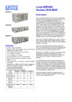
PULSE DECODE LEVEL SCAN:
After done the scan of pulse decode level, the system will show up detected value of each line in the
screen. Press “Y” to copy the detected value to Pulse Decode Level of System Setup screen. Or press
“N” or ESC key to cancel the copy.
NA means no found any signal in line.
SLOT 1 FXO
=== FXO D iagn ost ic Test == =
1.OF F-H O OK T EST
16 :32: 48 05/ 19/2 009
*2.P U LSE DEC ODE LEV EL SCA N
- ST ATU S :
Dete cte d V alue
L1
NA
L2
NA
L3
NA
L4
NA
L5
NA
L6
NA
L7
NA
L8
NA
L9
NA
L1 0
NA
Copy De tec ted Val ue to S yst em Setu p ( Pul se D eco de Leve l) (Y/ N)
<< p res s E SC k ey to retu rn to main me nu >>
27
L11
NA
L 12
NA
(dBm )
CHAPTER 3 TERMINAL OPERATION
3.2.5 Upgrade Firmw are
Press “G” from the Port Menu to start your flash download. Key in the server IP
and firmware file name. Then, press Enter to start the download.
LOOP AM3 440 -A
= == D own load Fir mwa re == =
1 6:3 3:3 1 05/ 19/ 20 0 9
ARRO W K EYS : CU RSO R M OVE, Pl eas e In put : n nn.n nn. nnn .nnn , B ACK SPAC E t o e dit
Bank 1 Fir mwar e V er. : V 2.0 1.0 1 04 /20 /20 09
(Go od)
Bank 2 Fir mwar e V er. : V 2.0 1.0 1 05 /07 /20 09
(Go od)
Work ing Fi rmwa re Ban k: 2
TFTP Se rve r IP
: 0 10. 003 .013 .01 0
Firm war e F ile Nam e
:
<< p res s E SC k ey to retu rn to main me nu >>
3.2.6 Unit Load Default Configuration
Press “Y” from Port Menu to return the default. Then press “Y” or “N” to confirm
the selection.
SLOT 1 FXO
=== U nit Me nu = ==
16:32:48 05/19/2009
Load de fau lt - ar e y ou s ure (Y /N)?
3.2.7 Unit Reset
Press “Z” from Port Menu to reset the unit. Then press “Y” or “N” to confirm the
selection.
SLOT 1 FX O
== = Un it Men u == =
16:32:48 05/19/2009
Rese t - ar e yo u s ure ? [ Y/N ]
If users enter "Y" to confirm the reset, the system will request users to enter the
password, LOOP, then press ENTER.
SLOT 1 FXO
=== U nit Me nu = ==
==>> En ter pas swo rd :
28
16:32:48 05/19/2009