1
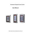
Product Specification
Wiring Connections
Colour
Function
Installation Procedure
Description
Keypad
1
Access Controller
User manual
1
Documentation
Screw driver
1
Φ20mm×60mm,Special for keypad
Rubber plug
2
Φ6mm×30 mm, used for fixing
Self tapping screws
2
Φ4mm×28 mm, used for fixing
Star screws
1
Φ3mm×6mm, used for fixing
Pink
BELL_A
Doorbell button one end
Pale blue
BELL_B
Doorbell button to the other end
Green
D0
WG output D0
White
D1
WG output D1
Grey
ALARM
Alarm negative(alarm positive
Yellow
OPEN
Brown
D_IN
Red
12V+
12V + DC Regulated Power Input
Black GND
12V -
DC Regulated Power Input
Blue
NO
Relay normally-on end
Purple
COM
Relay Public end, connect GND
Orange
NC
Relay Closed end
connected 12 V+)
connected GND)
Magnetic switch one end(the
other end connected GND)
(Connect positive electric lock "-")
Specification
Operating Voltage
DC 12V±10%
User Capacity
2000
Card Reading Distance
3-6 cm
Active Current
<60mA
Idle Current
25±5 mA
Lock Output Load
Max 3A
Alarm Output Load
Max 3A
Operating Temperature
-45ºC ~ 60ºC
Operating Humidity
10%- 90% RH
Waterproof
Conforms to IP68
Adjustable Door Relay time
0 - 99 seconds
Adjustable Alarm Time
0 - 3 minutes
Wiring Connections
Electric Lock, Exit Button, External Alarm,External reader
Remove the back cover from the keypad
using the supplied special screw driver
Exit button one end(the other end
(connect negative electric lock "-")
STEP 2
Qty Note
STEP 3
Name
STEP 1
Packing List
Gently pull the metal back plate cover
away from the main body of the reader.
• Drill 2 holes on the wall for the Self
tapping screws and I hole for the
cable
• Put the supplied rubber bungs to into
the two holes
• Fix the back cover firmly on the wall
with 2 Self tapping screws
• Thread the cable through the cable
hole
• Attach the keypad to the back cover.