1
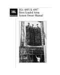
Cinema 5000 Series Screen Channel Systems User’s Guide TABLE OF CONTENTS 1. JBL 5000 SERIES................................................................................................................................2 1.1 THANK YOU FOR PURCHASING...............................................................................................................2 2. SYSTEM CONFIGURATIONS..........................................................................................................3 2.1 LOW FREQUENCY SECTION ...................................................................................................................3 2.2 MID FREQUENCY SECTION ....................................................................................................................4 2.3 HIGH FREQUENCY SECTION ..................................................................................................................4 3. SYSTEM SUPPORT MECHANISM - BRACKET ASSEMBLY ......................................................6 3.1 ASSEMBLY INSTRUCTIONS ....................................................................................................................7 4. DIGITAL SYSTEM CONTROL ......................................................................................................11 4.1 JBL DSC CONTROLLERS ....................................................................................................................11 4.2 DSC BLOCK DIAGRAM .......................................................................................................................11 4.3 THREE CHANNEL CONFIGURATION (LEFT, CENTER, RIGHT).................................................................12 4.4 FIVE CHANNEL CONFIGURATION (LEFT, LEFT-EXTRA, CENTER, RIGHT-EXTRA, RIGHT)........................12 4.5 SUBWOOFER CHANNEL .......................................................................................................................12 5. SYSTEM CONNECTIONS...............................................................................................................13 5.1 SYSTEM BLOCK DIAGRAMS .................................................................................................................13 5.2 WIRE RECOMMENDATIONS..................................................................................................................14 5.3 SPEAKER CONNECTIONS .....................................................................................................................14 6. POWER AMPLIFIER REQUIREMENTS ......................................................................................16 7. SPEAKER PLACEMENT ................................................................................................................18 7.1 VERTICAL PLACEMENT .......................................................................................................................18 7.2 HORIZONTAL SPACING .......................................................................................................................18 7.3 DISTANCE FROM SPEAKER TO SCREEN .................................................................................................19 7.4 HORN ARRAY AIMING ........................................................................................................................19 7.4.1 Vertical Plane.............................................................................................................................19 7.4.2 Horizontal Plane.........................................................................................................................19 7.5 BAFFLE LOADING ...............................................................................................................................20 7.6 FULL BAFFLE WALL ...........................................................................................................................20 8. SPECIFICATIONS ...........................................................................................................................22 8.1 5671 SCREEN CHANNEL SYSTEM ........................................................................................................22 8.2 5672 SCREEN CHANNEL SYSTEM ........................................................................................................23 8.3 5674 SCREEN CHANNEL SYSTEM ........................................................................................................24 9. WARRANTY INFORMATION........................................................................................................25 JBL Cinema 5000 Series - User’s Guide P/N 981-00040-00 CE page 1 C5KUG 1M 6/97 Cinema 5000 Series Screen Channel Systems User’s Guide 1. JBL 5000 Series 1.1 Thank you for purchasing... The Cinema 5000 Series Screen Channel systems represent the best of JBL loudspeaker technology for cinema screen channel applications. Each 5000 Series screen channel system is a three-way, tri-amplified design, intended to provide superior sound quality over many years of reliable service. There are three models of 5000 Series Screen Channel systems. All three use the same low frequency, mid-range, and high frequency drivers. Each system is scaled for a different room size. Therefore, they only differ in the number of low frequency transducers and physical size of the mid and high frequency horns. Each section of the 5000 Series Screen Channel system is optimized for the frequency range over which it operates. JBL Optimized Aperture horns and drivers provide ultra-low distortion reproduction for today’s demanding digital soundtracks. Your 5000 Series screen channel system is shipped in two cartons. One carton contains the low frequency section, and the second carton contains the mid and high frequency horns, drivers, mounting bracket and hardware. Please be sure to save this user’s manual as a reference guide in the event that this system is moved, reinstalled, or a change in ownership occurs. JBL Cinema 5000 Series - User’s Guide P/N 981-00040-00 CE page 2 C5KUG 1M 6/97 Cinema 5000 Series Screen Channel Systems User’s Guide 2. System Configurations 2.1 Low Frequency Section The low frequency section of your system uses JBL 2226 Vented Gap Cooled low frequency drivers. The 5671 Screen Channel system features the 5641 low frequency section, incorporating a single JBL 2226H 15” (380 mm) driver. Connections are made to two screw type terminals located on the top of the enclosure. . . . . . . . . . . The 5672 Screen Channel system features the 4648A low frequency section, incorporating two JBL 2226H 15” (380 mm) drivers. Connections are made to two screw type terminals located on the rear of the enclosure. . . . . . . . . . . The 5674 Screen Channel system features the 5644 low frequency section, incorporating four JBL 2226H 15” (380 mm) drivers, in a unique DiamondQuad array. This array minimizes destructive driver interaction effects while maximizing output and pattern control. Connections are made to four screw type terminals located on the top of the enclosure. Each driver pair is wired in parallel, resulting in two 4 ohm loads per enclosure. VERTICAL pair wired in parallel JBL Cinema 5000 Series - User’s Guide P/N 981-00040-00 CE HORIZONTAL pair wired in parallel page 3 C5KUG 1M 6/97 Cinema 5000 Series Screen Channel Systems User’s Guide 2.2 Mid Frequency Section The mid frequency section on all systems feature Optimized Aperture horn/driver technology for the lowest possible distortion. The 2392 or 2392-S midrange Optimized Aperture horns provides outstanding midrange pattern control. The 2490H midrange compression driver has a 4” voice coil and titanium diaphragm with a 3” exit, and is optimized for response between 250 Hz and 4000 Hz. The 5671 Screen Channel system features the 2392-S 30” horn, which is smaller in vertical and horizontal dimension to fit within the profile of the low frequency section, while maintaining midrange pattern control for smaller rooms. . . . . . . . . . . . . . . . . . . . . The 5672 and 5674 Screen Channel systems both feature the 2392 44” horn, which maintains midrange pattern control for the largest rooms. 2.3 High Frequency Section The high frequency section on all systems incorporate Optimized Aperture horn/driver technology for the lowest possible distortion. The HF driver is the JBL 2451H high frequency compression driver with neodymium-magnet structure. The 2451H is our most advanced compression driver, using our unique radial-ribbed 4” diaphragm and edgewound voice coil. The 5671 Screen Channel system uses the 2332 90°x 40° horn, mounted in a 3/8” plywood baffle board. The width of the baffle matches the width of the LF section and HF horn to make baffle wall installation easier. JBL Cinema 5000 Series - User’s Guide P/N 981-00040-00 CE page 4 C5KUG 1M 6/97 Cinema 5000 Series Screen Channel Systems User’s Guide . . . . . . . . . . . . . . . . . . . . JBL Cinema 5000 Series - User’s Guide P/N 981-00040-00 CE The 5672 and 5674 Screen Channel systems both use the 2352 90°x 40° horn, mounted in a 3/8” plywood baffle board. The width of the baffle matches the width of the MF horn to make baffle wall installation easier. page 5 C5KUG 1M 6/97 Cinema 5000 Series Screen Channel Systems User’s Guide 3. System Support Mechanism - Bracket Assembly The horn array bracket supplied with your 5000 Series Screen channel systems provides a simple way to mount and install the mid and high frequency horns and drivers on top of the low frequency section. For the 5672 and 5674 systems, the bracket assemblies are identical -- model number HB74. The 5671 system is shipped with a smaller version bracket with identical functions and features -model number HB71. baffle board 2352 HF horn 2352 HF horn front strap back strap screw through baffle board, into C-channel upright rail upright rails (“C” channel) throat section yoke (connects to throat section) upright supports (tilt adjustment bar) pre-set tilt positions mounting plate Front, rear, and side views of 5672/5674 bracket assembly baffle board 2332 HF horn front strap screw through baffle board, into upright rail back strap upright rails (“C” channel) yoke (connects to throat section) upright supports (tilt adjustment bar) 2332 HF horn throat section pre-set tilt positions mounting plate Front, rear, and side views of 5671 bracket assembly Once assembled, the horn array is adjusted for proper tilt angle using one of the available tilt angle holes, which are located on the upright rail sections of the bracket assembly. Each hole represents an increment of 2.5 degrees forward tilt. A maximum of 10 degrees forward tilt can be safely achieved without risk of exceeding the array’s center of gravity. Ten degrees of tilt should be the maximum required for today’s cinema designs, however the specific tilt angle depends on the room dimensions and floor slope of the seating area. See section 7.4, “Horn Array Aiming”, for more information on proper aiming once assembly is complete and ready for installation. JBL Cinema 5000 Series - User’s Guide P/N 981-00040-00 CE page 6 C5KUG 1M 6/97 Cinema 5000 Series Screen Channel Systems User’s Guide In the carton containing the midrange and high frequency components, you should find the following items: • • • • • • • • • Steel mounting plate Steel L-channel with hinges Upright supports for tilt adjustment (2) Yoke Horn baffle board Upright rail C-channels (2) Front strap Back strap Hardware for assembly count item (34)* 1/4-20 x 7/8 large button head, Philips screw, black (*5671 kit includes 24 pcs) (34)* 1/4 spring lock washer, regular, black (*5671 kit includes 24 pcs.) (44)* 1/4 flat washer, type A, black (*5671 kit includes 34 pcs.) (10) 1/4-20 hex nut (4) 5/16-18 x 5/8 large button head, Philips, black (4) 5/16 spring lock washer, type A (8) 5/16 flat washer, type A (4) 5/16-18 hex nut (6) #12-24 x 5/8 large button head, Philips screw (8) #12 flat washer, type A (6) #12 spring lock washer, regular (6) #12-24 hex nut 3.1 Assembly Instructions STEP 1. Make sure you have all of the pieces listed above. If items are missing, please contact your JBL Professional Representative immediately, or call JBL Professional at (818) 894-8850, ask for Customer Service & Parts. Outside the United States, please contact your JBL Professional Authorized Distributor. JBL Cinema 5000 Series - User’s Guide P/N 981-00040-00 CE page 7 C5KUG 1M 6/97 Cinema 5000 Series Screen Channel Systems User’s Guide STEP 2. Attach baffle board to large horn (2392 or 2392-S). baffle board 2352 HF horn front strap screw through baffle board, into C-channel upright rail Using two C-channel upright rails, fasten through top TWO holes on front of baffle board with 1/4-20 x 7/8 Philips screws with 1/4” spring lock and flat washers into pemnuts in the C-channel. Flat surface of Cchannel should be placed against back of baffle board and along the rear of horn flange. Fasten horn to Cchannel using same type screws and washers into pemnuts through second and third holes only, being careful not to overtighten. The pair of holes at baffle board bottom and top of horn will be used to fasten front strap along the “seam”, or juncture of baffle board and horn flange. Cover the seam of the top of horn and bottom of baffle board with front strap. Fasten two ends of front strap (two holes at each end of strap) into C-channel with 1/420 x 7/8 Philips screws with 1/4” spring lock and flat washers into pemnuts in the C-channel as before. front view 5672/5674 horn assembly Fasten screws through top horn flange and bottom of baffle board with 1/4-20 x 7/8 Philips screws with 1/4” spring lock and flat washers into the back strap, positioned on rear side of baffle/horn. Do not overtighten. Only screw heads with washers should be visible from the front view of assembly. STEP 3. Attach HF horn to baffle board. back strap upright rails (“C” channel) yoke (connects to throat section) upright supports (tilt adjustment bar) (See diagram above). Front load the HF horn using 1/4-20 x 7/8 Philips screws into 1/4” spring lock and flat washers through the horn flange and baffle board, and secure on rear of board with flat washer and 1/4-20 hex nut. 2352 horn with 5672 and 5674 systems will require ten (10) sets of this hardware; 2332 horn with 5671 system will require four (4) sets of this hardware. rear view 5672/5674 horn assembly STEP 4. Connect Steel L-channel with hinges to bottom flange of large horn (2392 or 2392-S). (see illustration next page) Push four (4) 1/4-20 Philips screws with spring lock and flat washers through four holes along bottom front of horn flange and thread into pemnuts on L-channel. JBL Cinema 5000 Series - User’s Guide P/N 981-00040-00 CE page 8 C5KUG 1M 6/97 Cinema 5000 Series Screen Channel Systems User’s Guide MF horn flange Philips head nut mounting plate hinge hinge assembly & connecting horn array to mounting plate (side view) STEP 5. Sub-assembly of support mechanism and mounting plate. The mounting plate used with all three 5000 Series systems (HB71 used with 5671, HB74 used with both 5672 and 5674) is the same. Note, however, that there are two sets of “mounting tabs”, which are positioned for both the 2392 horn used with the 5672 and 5674 systems, and the 2392-S horn used with the 5671 system. mounting tab for 5671 mounting tab for 5672,5674 close-up of mounting plate subassembly Select the appropriate mounting tab and fasten both upright supports to outside of tab with 5/1618 Philips bolts, 5/16 flat washers (1 per side), lock washers, and 5/16-18 hex nut; hand tighten only, as this is the pivot point for tilt adjustments. Connect the yoke between the upright supports at the bottom set of pre-drill tilt adjust holes, again using 5/16 Philips screws. Final tilt adjustment can be made after completing assembly. STEP 6. Fasten bottom horn flange to mounting plate. Lay horn array on flat surface, face down. Position mounting plate near L-channel with hinge and fasten using #12-24 x 5/8 Philips screws, #12 flat washers, #12 spring lock washers, and #12-24 hex nuts. (See detail in figure at STEP 4.) STEP 7. JBL Cinema 5000 Series - User’s Guide P/N 981-00040-00 CE page 9 C5KUG 1M 6/97 Cinema 5000 Series Screen Channel Systems User’s Guide Connect large horn throat section to large horn. Using nuts, bolts, and washers supplied with the horn, connect sections together through only the top six holes. Connect the remaining two bolts through yoke and then through throat section and horn. yoke STEP 8. Place horn array on top of LF enclosure. Completed horn array and bracket assembly may now be placed on top of your LF cabinet, and secured through the mounting plate to cabinet using the large screws provided with your LF section. Do not tighten completely until side-to-side (“yaw’) aiming adjustments are made. STEP 9. Adjust tilt of horn array. When installation of system is complete, final tilt adjustments can be made, by selecting the appropriate hole in the upright supports. When desired angle is determined, tighten nut/bolts to a torque level of 22 in/lbs. 10 degrees 7.5 degrees After this step is complete, the compression drivers may be attached to the horns. 5 degrees 2.5 degrees 0 degrees After assembly is complete, and your system is installed, check to be sure that all nuts are fully tightened to a torque level of 22 in/lbs. For mounting of bracket mounting base to LF cabinet, a torque level of 40 in/lbs should be applied. Connect to mounting tab on mounting plate Upright support tilt adjustment bar JBL Cinema 5000 Series - User’s Guide P/N 981-00040-00 CE page 10 C5KUG 1M 6/97 Cinema 5000 Series Screen Channel Systems User’s Guide 4. Digital System Control 4.1 JBL DSC Controllers The recommended controller for 5000 Series three-way screen channel systems is the JBL family of digital system controllers. For detailed operational information, please refer to the Owner’s Manual supplied with your digital system controller. In typical 3-way operation, each input is routed to three outputs, providing low, mid, and high frequency separation. The JBL DSC 260 is a 2-input, 6-output device, and is shipped with factory pre-set tunings for each of the 5000 Series screen channel systems. These tunings provide crossover, signal delay, and equalization settings which provide a good starting point for achieving optimal system performance. However, since each installation and acoustic environment is different, typically some equalization adjustments will be necessary to optimize the system for the specific acoustic conditions in which the system is installed. 4.2 DSC Block Diagram In a typical three channel (L,C,R) screen system, with each channel tri-amplifying a 5000 Series 3-way system, the two DSC digital controllers are configured as follows: First unit Digital Signal Processor (DSC260) Channel 1 LOW MID HIGH input Channel 2 LOW MID HIGH input JBL Cinema 5000 Series - User’s Guide P/N 981-00040-00 CE page 11 C5KUG 1M 6/97 Cinema 5000 Series Screen Channel Systems User’s Guide Second Unit Digital Signal Processor (DSC260) Channel 1 LOW MID HIGH input Channel 2 SUB OUT 2 OUT 3 input 4.3 Three Channel Configuration (Left, Center, Right) For standard three screen channel cinema systems, two DSC controllers are required. This is because each device is a two input device. It is recommended that one device is used for Left and Right channels, and the second device is used for Center and Subwoofer channels. 4.4 Five Channel Configuration (Left, Left-extra, Center, Right-extra, Right) For five channel screen systems, such as with Sony’s SDDS digital process, three DSC controllers are required. This is because each device is a two input device. It is recommended that one device is used for Left and Right channels, a second device for Left-extra and Right-extra, and the third device is used for Center and Subwoofer channels. 4.5 Subwoofer Channel The DSC controller can be used for subwoofer channel bandpass filtering, time alignment, and equalization. JBL Cinema 5000 Series - User’s Guide P/N 981-00040-00 CE page 12 C5KUG 1M 6/97 Cinema 5000 Series Screen Channel Systems User’s Guide 5. System Connections 5.1 System block diagrams The following are suggested system block diagrams for configuring the 5000 Series 3-way screen channels systems. In each case, the crossover is assumed to be a 2-input, 6-output digital controller, such as the JBL DSC 260. Each diagram illustrates the use of the remaining channel on the second DSC unit for subwoofer signal processing. The number of subwoofer speakers is determined by the room volume. For the purposes of this manual, the block diagram shows how to use remaining channels of power amplifiers after 3-way triamplification is accomplished. 5671 Screen Channel Systems (for small rooms, under 250 seats) Amplifiers L-High L-Mid Digital Signal Processors (Crossover, delay, eq) Digital Film Sound Processor L-Low R-Low L ch. 1 ch. 2 max. 300w/ch 8 ohm ch. 1 ch. 2 ch. 1 ch. 2 max. 800w/ch 8 ohm ch. 1 ch. 2 ch. 1 ch. 2 max. 300w/ch 8 ohm ch. 1 ch. 2 max. 300w/ch 8 ohm ch. 1 ch. 2 max. 800w/ch 8 ohm ch. 1 ch. 2 LEFT RIGHT R-High R R-Mid C Sub C-High ch. 1 C-Mid ch. 2 CENTER C-Low ch. 1 ch. 2 Sub (1) SUB Typical system block diagram for 5671 3-way screen channel system with subwoofers 5672 Screen Channel Systems (for medium-large rooms, under 500 seats) Amplifiers L-High L-Mid Digital Signal Processors (Crossover, delay, eq) Digital Film Sound Processor L L-Low R-Low max. 300w/ch 8 ohm ch. 1 ch. 2 max. 800w/ch 8 ohm ch. 1 ch. 2 ch. 1 ch. 2 max. 300w/ch 8 ohm ch. 1 ch. 2 ch. 1 ch. 2 max. 300w/ch 8 ohm ch. 1 ch. 2 ch. 1 ch. 2 max. 800w/ch 8 ohm ch. 1 ch. 2 ch. 2 RIGHT R-High R R-Mid C Sub LEFT ch. 1 ch. 1 ch. 2 C-High C-Mid CENTER C-Low Subs max. 800w/ch 8 ohm SUB Additional SUBS Typical system block diagram for 5672 3-way screen channel system with subwoofers JBL Cinema 5000 Series - User’s Guide P/N 981-00040-00 CE page 13 C5KUG 1M 6/97 Cinema 5000 Series Screen Channel Systems User’s Guide 5674 Screen Channel Systems (for large rooms, over 500 seats) Amplifiers L-High L-Mid Digital Signal Processors (Crossover, delay, eq) Digital Film Sound Processor ch. 1 ch. 2 ch. 1 ch. 2 max. 1200w/ch 4 ohm (parallel inputs) ch. 1 ch. 2 max. 300w/ch 8 ohm ch. 1 ch. 2 max. 1200w/ch 4 ohm (parallel inputs) ch. 1 ch. 2 max. 300w/ch 8 ohm ch. 1 ch. 2 max. 1200w/ch 4 ohm (parallel inputs) ch. 1 ch. 2 LEFT L-Low ch. 1 L R R-High C R-Mid Sub max. 300w/ch 8 ohm ch. 1 ch. 2 RIGHT R-Low ch. 1 C-High C-Mid ch. 1 ch. 2 CENTER C-Low ch. 1 Subs ch. 1 max. 800w/ch 8 ohm parallel inputs ch. 1 ch. 2 SUBS max. 800w/ch 8 ohm Additional SUBS Typical system block diagram for 5674 3-way screen channel system with subwoofers 5.2 Wire recommendations All speaker connections from the amplifier to the speakers should be made with appropriate gauge cable to minimize insertion loss. Insertion loss is signal attenuation resulting from the insertion of a device or circuit into the signal path. It is measured in decibels, increases proportionally to length of cable, and is inversely proportional to the impedance of the load (speaker). Use this chart to determine the size wire necessary for the length of the speaker cable run. Estimate the length of your cable run and locate along the horizontal axis. Then trace the vertical line up until it intersects the solid line equal to your total load impedance. Then find the appropriate wire size along the vertical axis. The object is to minimize insertion loss, and a level not to exceed -0.5 dB is considered acceptable. Greater insertion loss will result in frequency response anomalies in the cinema. W ire Gauge Chart for 0.5 dB Loss 20 15 16 Ohm Load 8 Ohm Load 10 4 Ohm Load 5 0 50 100 150 200 250 300 Length of Run (ft.) 5.3 Speaker Connections JBL Cinema 5000 Series - User’s Guide P/N 981-00040-00 CE page 14 C5KUG 1M 6/97 Cinema 5000 Series Screen Channel Systems User’s Guide For connecting speaker cables to LF sections, spade lug connections are recommended. The proper size spade lug should be crimped to the bare wire end of the cable and securely fastened beneath the screw terminals on the LF cabinet, carefully noting correct polarity. JBL HF compression drivers use push spring-type posts, and again, polarity should be maintained throughout the systems. JBL Cinema 5000 Series - User’s Guide P/N 981-00040-00 CE page 15 C5KUG 1M 6/97 Cinema 5000 Series Screen Channel Systems User’s Guide 6. Power Amplifier Requirements The following series of graphs provide a quick method for determining the power needed to reach 85 dB and 105 dB at the 2/3 distance in a typical theatre. Each section (HF, MF, and LF) is individually graphed. 85 dB is the typical nominal level for dialog, and 105 dB is considered peak level for today’s digital film sound sources. To use the graphs, find the 2/3 room distance for the room in question along the X-axis (horizontal). Then move up the Y-axis to the 85 and 105 dB curves. The power requirement can then be read along the Y-axis. To ensure adequate headroom, the power levels for 105 dB should be considered minimum power requirements. These figures do not take into account any room reflections, thus these figures are conservative. Cinema 5000 - Power Requirements: High Frequency 1000 105 dB Power (W) 100 10 85 dB 1 0.1 0 20 40 60 80 100 120 140 160 140 160 Two-Thirds of Depth of Room (ft.) Cinema 5000 - Power Requirements: Mid Frequency 1000 105 dB Power (W) 100 10 85 dB 1 0.1 0 20 40 60 80 100 120 Two-Thirds of Depth of Room (ft.) JBL Cinema 5000 Series - User’s Guide P/N 981-00040-00 CE page 16 C5KUG 1M 6/97 Cinema 5000 Series Screen Channel Systems User’s Guide Cinema 5000 - Power Requirements: Low Frequency 10000 105 dB Power (W) 1000 100 85 dB 10 1 0.1 0 20 40 60 80 100 120 140 160 Two-Thirds of Depth of Room (ft.) JBL Cinema 5000 Series - User’s Guide P/N 981-00040-00 CE page 17 C5KUG 1M 6/97 Cinema 5000 Series Screen Channel Systems User’s Guide 7. Speaker Placement The following guidelines will help in providing optimal aiming and placement to best match the perceived location of the sound to the picture on the screen. 7.1 Vertical Placement The “seam” (front strap of bracket) where the HF baffle board meets the MF horn should be located between 2/3 to 5/8 the total screen height when screen is masked for the tallest film format. rear wall behind screen perf. screen 5/8 to 2/3 screen height absorptive baffle wall 7.2 Horizontal Spacing For a 3-channel (L,C,R) system, L and R speaker channels should be placed equidistant from center of screen image area, so that they are just inside the screen area when screen is masked for the widest format (typically 2.35:1). Acoustically transparent side masking should be used to prevent blocking of HF when side masking is moved in for “flat” picture format. For 5-channel systems, Left-extra and right-extra should be placed equidistant between Left and Center, and Right and Center. 2.35:1 1.85:1 L Le . . . . . . . . . . . . . . . . . . . . . JBL Cinema 5000 Series - User’s Guide P/N 981-00040-00 CE C . . . . . . . . . Re R . . . . . . . . . . . . . . . . . . . . page 18 C5KUG 1M 6/97 Cinema 5000 Series Screen Channel Systems User’s Guide 7.3 Distance from speaker to screen After finalizing the tilt aim adjustment the HF/MF horn array should be placed as close to the screen as possible. There are two reasons for this: 1) JBL has found that reflections behind the screen between the horn and the rear of the screen can cause room response anomalies. 2) The perforations actually cause the dispersion pattern in the room to widen at certain frequencies, and this effect is made worse as the distance between the speaker and screen increases. 7.4 Horn Array Aiming 7.4.1 Vertical Plane In typical cinemas, best coverage is usually attained by aiming the high frequency horns at the last row of seating. In more steeply raked “stadium” style houses, the horns may not require any tilt at all; in these cases, care should be taken to minimize acoustically reflective surfaces in the rear wall and ceiling surfaces. 7.4.2 Horizontal Plane All screen speakers should be aimed to converge at a point about 2/3 of the length of the room. (seating area) 2/3 JBL Cinema 5000 Series - User’s Guide P/N 981-00040-00 CE 1/3 page 19 C5KUG 1M 6/97 Cinema 5000 Series Screen Channel Systems User’s Guide 7.5 Baffle loading For optimal results, JBL Professional recommends the installation of screen channel speakers in a full baffle wall, such as recommended by Lucasfilm/THX and others. Good results can also be achieved using reinforced baffle “wings” on either side of the speaker system stacks, as long as they are constructed using high quality materials and are free of resonances and vibrations. The preferred baffle wall design extends from interior theatre wall-to-wall, and floor to ceiling, essentially creating a room behind the screen, into which the speakers are flush mounted, firing into the auditorium. For practical and budgetary reasons, this concept can be modified, still yielding good results, but optimal performance is typically achieved in a full baffle wall condition. 7.6 Full Baffle Wall The speakers should be located in the baffle wall so that the front of the LF cabinet is flush with the front of the baffle wall acoustical treatment material (typically black faced duct-liner). screen The distance from the screen to the baffle wall needs to allow for tilt adjustments of the HF/MF horn array. Remember that as the tilt angle increases, the top horn gets closer to the rear of the screen. For example, at maximum tilt (10°) the 5674 or 5672 horn array will require approximately 11.2 inches of clearance between the baffle wall and d the screen. perf. screen absorptive baffle wall For 5672 or 5674 system Tilt angle wall) 0° 2.5° 5° 7.5° 10° d (Distance that top of horn array protrudes from baffle 0 inches (0 cm) 3 inches (7 cm) 6 inches (14 cm) 8.4 inches (21.2 cm) 11.2 inches (28.3 cm) For 5671 system Tilt angle wall) 0° d (Distance that top of horn array protrudes from baffle 0 inches (0 cm) 2.5° 1.75 inches (4.5 5° 3.5 inches (8.9 cm) cm) 7.5° 10° 5.25 inches (13.3 cm) 7 inches (17.7 cm) NOTE: THX is a registered trademark of Lucasfilm, Ltd. JBL Cinema 5000 Series - User’s Guide P/N 981-00040-00 CE page 20 C5KUG 1M 6/97 Cinema 5000 Series Screen Channel Systems User’s Guide Panel or dense “gasketing” perf. screen absorptive baffle wall Once final tilt and aiming adjustments have been made, the sides and top of each screen channel should be sealed to the baffle wall. This can be done with a solid plywood triangular section on each side of the mid/high horn array, and a rectangular section across the top. It should be made a stiff as possible, and treated on the front face with the same HF sound absorptive material (1.5” ductliner or “Sonex” type material) as used on the front face of the baffle wall. JBL Cinema 5000 Series - User’s Guide P/N 981-00040-00 CE page 21 C5KUG 1M 6/97 Cinema 5000 Series Screen Channel Systems User’s Guide 8. Specifications 8.1 5671 Screen Channel System Frequency Range (-10 dB): Frequency Response (+/- 3 dB): Hor. Coverage Angle (-6 dB): Vert. Coverage Angle (-6 dB): Directivity Factor (Q): Directivity Index (DI): Calculated Maximum Output: 40 Hz - 16 kHz 50 Hz - 12.5 kHz 80°, averaged 300 Hz to 16 kHz 50°, averaged 300 Hz to 16 kHz 11 10.4 131 dB-SPL @ 1m 111 dB-SPL @ 10 m Recommended Crossover Freq. LF/MF: 320 Hz, MF/HF: 2.3 kHz Recommended Controller: JBL DSC family of digital controllers; tunings available in memory Dimensions (HxWxD): 1483 mm x 774.7 mm x 736.6 mm (58.375 in. x 30.5 in. x 29 in.) Net Weight: 80.2 kg (177 lbs.) Shipping Weight: 89.4 kg (197 lbs.) Transducers: Low Frequency: 5641 LF section: One 2226H 380 mm (15 in.) dia., 100 mm (4 in.) edgewound ribbon voice coil in 5501 LF enclosure Nominal impedance: 8 ohms Input Power Rating: 600 W, AES; 2400 W into 8 ohms Max. Recommended Amplifier Sensitivity: 97 dB, 1 W @ 1 m (3.3 ft.) Input Connectors:Barrier Strip Dimensions (HxWxD): 546 mm x 775 mm x 448 mm (21.5 in. x 30.5 in. x 17.625 in.) Net Weight: 28.6 kg (63 lbs.) Shipping Weight: 32.7 kg (72 lbs.) Mid Frequency: Nominal impedance: Input Power Rating: Sensitivity: Net Weight: High Frequency: Nominal impedance: Input Power Rating: Sensitivity: Net Weight: 2392-S midrange horn 2490H midrange driver; 100 mm (4 in.) edgewound ribbon voice coil 8 Ohms 100 W, AES; 400 W Max. Recommended Amplifier 115 dB, 1 W @ 1 m (3.3 ft.) 26.3 kg (58 lbs.) 2332 horn 2451H driver; 100 mm (4 in.) edgewound ribbon voice coil 8 Ohms 75 W, AES; 300 W Max. Recommended Amplifier 112 dB, 1 W @ 1 m (3.3 ft.) 7.26 kg (16 lbs.) JBL Cinema 5000 Series - User’s Guide P/N 981-00040-00 CE page 22 C5KUG 1M 6/97 Cinema 5000 Series Screen Channel Systems User’s Guide 8.2 5672 Screen Channel System Frequency Range (-10 dB): Frequency Response (+/- 3 dB): Hor. Coverage Angle (-6 dB): Vert. Coverage Angle (-6 dB): Directivity Factor (Q): Directivity Index (DI): Calculated Maximum Output: 35 Hz - 16 kHz 45 Hz - 12.5 kHz 80°, averaged 300 Hz to 16 kHz 45°, averaged 300 Hz to 16 kHz 11 10.4 137 dB-SPL @ 1 m 117 dB-SPL @ 10 m Recommended Crossover Freq. LF/MF: 297 Hz, MF/HF: 2.5 kHz Recommended Controller: JBL DSC family of digital controllers; settings available in memory Dimensions (HxWxD): 2768.6 mm x 1118 mm x 812.8 mm (109 in. x 44 in. x 32 in.) Net Weight: 87.3 kg (192.5 lbs.) Shipping Weight:96.4 kg (212.5 lbs.) Transducers: Low Frequency: 4648A LF Section: Two 2226H 380 mm (15 in.) dia., 100 mm (4 in.) edgewound ribbon voice coil, in 4508A LF enclosure Nominal impedance: 4 ohms Input Power Rating: 1200 W, AES; 4800 W into 4Ω Max. Recommended Amplifier Sensitivity: 100 dB, 1 W @ 1 m (3.3 ft.) Input Connectors:Barrier Strip Dimensions (HxWxD): 991 mm x 648 mm x 451 mm (39 in. x 25.5 in. x 17.75 in.) Net Weight: 61.2 kg (135 lbs.) Shipping Weight:68 kg (150 lbs.) Mid Frequency: Nominal impedance: Input Power Rating: Sensitivity: Net Weight: High Frequency: Nominal impedance: Input Power Rating: Sensitivity: Net Weight: 2392 midrange horn 2490H midrange driver; 100 mm (4 in.) edgewound ribbon voice coil 8 Ohms 100 W, AES; 400 W Max. Recommended Amplifier 115 dB, 1 W @ 1 m (3.3 ft.) 28.35 kg (62.5 lbs.) 2352 horn 2451H driver; 100 mm (4 in.) edgewound ribbon voice coil 8 Ohms 75 W, AES; 300 W Max. Recommended Amplifier 112 dB, 1 W @ 1 m (3.3 ft.) 7.26 kg (16 lbs.) JBL Cinema 5000 Series - User’s Guide P/N 981-00040-00 CE page 23 C5KUG 1M 6/97 Cinema 5000 Series Screen Channel Systems User’s Guide 8.3 5674 Screen Channel System Frequency Range (-10 dB): Frequency Response (+/- 3 dB): Hor. Coverage Angle (-6 dB): Vert. Coverage Angle (-6 dB): Directivity Factor (Q): Directivity Index (DI): Calculated Maximum Output: 35 Hz - 16 kHz 45 Hz - 12.5 kHz 80°, averaged 300 Hz to 16 kHz 45°, averaged 300 Hz to 16 kHz 11 10.4 137 dB-SPL @ 1m 117 dB-SPL @ 10 m Recommended Crossover Freq. LF/MF: 297 Hz, MF/HF: 2.5 kHz Recommended Controller: JBL DSC family of digital controllers; tunings available in memory Dimensions (HxWxD): 2895.6 mm x 1118 mm x 812.8 mm (114 in. x 44 in. x 32 in.) Net Weight: 171.69 kg (378.5 lbs.) Shipping Weight:190.5 kg (420 lbs.) Transducers: Low Frequency: 5644 LF Section: Four 2226H 380 mm (15 in.) dia., 100 mm (4 in.) edgewound ribbon voice coil, in 5504 LF enclosure with DiamondQuad driver array Nominal impedance: Each pair in parallel; 4Ω load per driver pair Input Power Rating: Per driver pair: 1200 W, AES; 4800 W into 4Ω Max. Recommended Amplifier Sensitivity: 103 dB, 1 W @ 1 m (3.3 ft.) Input Connectors:Two sets of “+” and “-” Barrier Strips Dimensions (HxWxD): 1118 mm x 1118 mm x 623 mm (44 in. x 44 in. x 24.5 in.) Net Weight: 136 kg (300 lbs.) Shipping Weight:145.2 kg (320 lbs.) Mid Frequency: Nominal impedance: Input Power Rating: Sensitivity: Net Weight: High Frequency: Nominal impedance: Input Power Rating: Sensitivity: Net Weight: 2392 midrange horn 2490H midrange driver; 100 mm (4 in.) edgewound ribbon voice coil 8 Ohms 100 W, AES; 400 W Max. Recommended Amplifier 115 dB, 1 W @ 1 m (3.3 ft.) 28.35 kg (62.5 lbs.) 2352 midrange horn 2451H midrange driver; 100 mm (4 in.) edgewound ribbon voice coil 8 Ohms 75 W, AES; 300 W Max. Recommended Amplifier 112 dB, 1 W @ 1 m (3.3 ft.) 7.26 kg (16 lbs.) JBL Cinema 5000 Series - User’s Guide P/N 981-00040-00 CE page 24 C5KUG 1M 6/97 Cinema 5000 Series Screen Channel Systems User’s Guide 9. Warranty Information All JBL Cinema 5000 Series screen channel systems are backed by a 5-year limited warranty. For complete warranty information, within the continental United States, Hawaii, and Alaska, please refer to the warranty card enclosed with your product. In other areas of the world, please contact your local JBL distributor. JBL Cinema 5000 Series - User’s Guide P/N 981-00040-00 CE page 25 C5KUG 1M 6/97