1
User’s
Manual
Yokogawa Electric Corporation
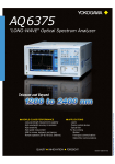
Model 810518801
64Mbit Program Pattern Option
IM 810518801-61E
1st Edition
Introduction
Thank you for your purchasing of this 64Mbit Program Pattern Option.
This option consists of the pattern editor application software (CD-ROM), designed for easy
creation of program patterns for the AQ2200-601 10Gbit/s BERT Module, a compact flash
card (CF) and a PC card adapter for the CF.
This manual describes the functions, operating procedures, and handling precautions
necessary to operate the pattern editor.
Before starting operation of this option, thoroughly read this manual to use the product
properly.
After reading this manual, always store it in a safe place where all concerned personnel can
refer to it immediately.
This manual is useful if the operator have forgotten proper operation steps during operation.
For the functions, operating procedures, and handling precautions of the BERT module and
frame controller, refer to their respective manuals.
Contents of the Package
z CD-ROM (for installation of the software): 1
z Compact flash (CF) (for storing created data): 1
z PC card adapter for CF: 1
z User’s manual (this manual): 1
z Model/specification code: 810518801/M
Notes
z The contents of this manual are subject to change without prior notice as a result of
continuing improvements to the instrument's performance and functions.
The figures given in this manual may differ from those that actually appear on your screen.
z Every effort has been made in the preparation of this manual to ensure the accuracy of its
contents. However, should you have any questions or find any errors, please contact your
nearest YOKOGAWA dealer.
z Copying or reproducing all or any part of the contents of this manual without the permission
of Yokogawa Electric Corporation is strictly prohibited.
z This software can be installed on more than one computer.
However, program patterns created by this software can run only on the AQ2200-601
10Gbit/s BERT Module to which the option has been implemented.
z Transfer or lending of this software to any third party is prohibited.
z Yokogawa Electric Corporation provides no guarantees other than for physical deficiencies
found on the original disk upon opening the product package.
z Yokogawa Electric Corporation shall not be held responsible by any party for any losses or
damage, direct or indirect, caused by the use or any unpredictable defect of the product.
Trademarks
z Microsoft, MS-DOS, and Windows are either registered trademarks or trademarks of
Microsoft Corporation in the United States and/or other countries.
z Adobe and Acrobat are trademarks of Adobe Systems Incorporated.
z For purposes of this manual, the TM and ® symbols do not accompany their respective
trademark names or registered trademark names.
z Other product names are trademarks or registered trademarks of their respective holders.
Revisions
z 1st Edition:
March 2005
1st Edition : March 2005 (YK)
All Rights Reserved, Copyright © 2005 Yokogawa Electric Corporation
IM810518801-61E
i
Terms and Conditions of the Software License
Yokogawa Electric Corporation, a Japanese corporation (hereinafter called "Yokogawa"), grants permission to use this Yokogawa Software
Program (hereinafter called the "Licensed Software") to the Licensee on the conditions that the Licensee agrees to the terms and conditions
stipulated in Article 1 hereof.
You, as the Licensee (hereinafter called "Licensee"), shall agree to the following terms and conditions for the software license (hereinafter called
the "Agreement") based on the use intended for the Licensed Software.
Please note that Yokogawa grants the Licensee permission to use the Licensed Software under the terms and conditions herein and in no event
shall Yokogawa intend to sell or transfer the Licensed Software to the Licensee.
Licensed Software Name: 64Mbit Program Pattern Option (For AQ2200-601 10Gbit/s BERT Module)
Number of License: Free
Article 1 (Scope Covered by these Terms and Conditions)
1.1
1.2
The terms and conditions stipulated herein shall be applied to any Licensee who purchases the Licensed Software on the condition that
the Licensee consents to agree to the terms and conditions stipulated herein.
The "Licensed Software" herein shall mean and include all applicable programs and documentation, without limitation, all proprietary
technology, algorithms, and know-how such as a factor, invariant or process contained therein.
Article 2 (Grant of License)
2.1
2.2
2.3
2.4
2.5
2.6
2.7
2.8
Yokogawa grants the Licensee, for the purpose of single use, non-exclusive and non-transferable license of the Licensed Software with
the license fee separately agreed upon by both parties.
The Licensee is, unless otherwise agreed in writing by Yokogawa, not entitled to copy, change, sell, distribute, transfer, or sublicense
the Licensed Software.
The Licensed Software shall not be copied in whole or in part except for keeping one (1) copy for back-up purposes. The Licensee shall
secure or supervise the copy of the Licensed Software by the Licensee itself with great, strict, and due care.
In no event shall the Licensee dump, reverse assemble, reverse compile, or reverse engineer the Licensed Software so that the
Licensee may translate the Licensed Software into other programs or change it into a man-readable form from the source code of the
Licensed Software. Unless otherwise separately agreed by Yokogawa, Yokogawa shall not provide the Licensee the source code for the
Licensed Software.
The Licensed Software and its related documentation shall be the proprietary property or trade secret of Yokogawa or a third party
which grants Yokogawa the rights. In no event shall the Licensee be transferred, leased, sublicensed, or assigned any rights relating to
the Licensed Software.
Yokogawa may use or add copy protection in or onto the Licensed Software. In no event shall the Licensee remove or attempt to
remove such copy protection.
The Licensed Software may include a software program licensed for re-use by a third party (hereinafter called "Third Party Software",
which may include any software program from affiliates of Yokogawa made or coded by themselves.) In the case that Yokogawa is
granted permission to sublicense to third parties by any licensors (sub-licensor) of the Third Party Software pursuant to different terms
and conditions than those stipulated in this Agreement, the Licensee shall observe such terms and conditions of which Yokogawa
notifies the Licensee in writing separately.
In no event shall the Licensee modify, remove or delete a copyright notice of Yokogawa and its licenser contained in the Licensed
Software, including any copy thereof.
Article 3 (Restriction of Specific Use)
3.1
3.2
The Licensed Software shall not be intended specifically to be designed, developed, constructed, manufactured, distributed or
maintained for the purpose of the following events:
a)
Operation of any aviation, vessel, or support of those operations from the ground;,
b)
Operation of nuclear products and/or facilities;,
c)
Operation of nuclear weapons and/or chemical weapons and/or biological weapons; or
d)
Operation of medical instrumentation directly utilized for humankind or the human body.
Even if the Licensee uses the Licensed Software for the purposes in the preceding Paragraph 3.1, Yokogawa has no liability to or
responsibility for any demand or damage arising out of the use or operations of the Licensed Software, and the Licensee agrees, on its
own responsibility, to solve and settle the claims and damages and to defend, indemnify or hold Yokogawa totally harmless, from or
against any liabilities, losses, damages and expenses (including fees for recalling the Products and reasonable attorney's fees and
court costs), or claims arising out of and related to the above-said claims and damages.
Article 4 (Warranty)
4.1
4.2
4.3
4.4
4.5
ii
The Licensee shall agree that the Licensed Software shall be provided to the Licensee on an "as is" basis when delivered. If defect(s),
such as damage to the medium of the Licensed Software, attributable to Yokogawa is found, Yokogawa agrees to replace, free of
charge, any Licensed Software on condition that the defective Licensed Software shall be returned to Yokogawa's specified authorized
service facility within seven (7) days after opening the Package at the Licensee's expense. As the Licensed Software is provided to the
Licensee on an "as is" basis when delivered, in no event shall Yokogawa warrant that any information on or in the Licensed Software,
including without limitation, data on computer programs and program listings, be completely accurate, correct, reliable, or the most
updated.
Notwithstanding the preceding Paragraph 4.1, when third party software is included in the Licensed Software, the warranty period and
terms and conditions that apply shall be those established by the provider of the third party software.
When Yokogawa decides in its own judgement that it is necessary, Yokogawa may from time to time provide the Licensee with Revision
upgrades and Version upgrades separately specified by Yokogawa (hereinafter called "Updates").
Notwithstanding the preceding Paragraph 4.3, in no event shall Yokogawa provide Updates where the Licensee or any third party
conducted renovation or improvement of the Licensed Software.
THE FOREGOING WARRANTIES ARE EXCLUSIVE AND IN LIEU OF ALL OTHER WARRANTIES OF QUALITY AND
PERFORMANCE, WRITTEN, ORAL, OR IMPLIED, AND ALL OTHER WARRANTIES INCLUDING ANY IMPLIED WARRANTIES OF
IM810518801-61E
Terms and Conditions of the Software License
4.6
MERCHANTABILITY OR FITNESS FOR A PARTICULAR PURPOSE ARE HEREBY DISCLAIMED BY YOKOGAWA AND ALL THIRD
PARTIES LICENSING THIRD PARTY SOFTWARE TO YOKOGAWA.
Correction of nonconformity in the manner and for the period of time provided above shall be the Licensee's sole and exclusive remedy
for any failure of Yokogawa to comply with its obligations and shall constitute fulfillment of all liabilities of Yokogawa and any third party
licensing the Third Party Software to Yokogawa (including any liability for direct, indirect, special, incidental or consequential damages)
whether in warranty, contract, tort (including negligence but excluding willful conduct or gross negligence by Yokogawa) or otherwise
with respect to or arising out of the use of the Licensed Software.
Article 5 (Infringement)
5.1
5.2
5.3
5.4
If and when any third party should demand injunction, initiate a law suit, or demand compensation for damages against the Licensee
under patent right (including utility model right, design patent, and trade mark), copy right, and any other rights relating to any of the
Licensed Software, the Licensee shall notify Yokogawa in writing to that effect without delay.
In the case of the preceding Paragraph 5.1, the Licensee shall assign to Yokogawa all of the rights to defend the Licensee and to
negotiate with the claiming party. Furthermore, the Licensee shall provide Yokogawa with necessary information or any other assistance
for Yokogawa's defense and negotiation. If and when such a claim should be attributable to Yokogawa, subject to the written notice to
Yokogawa stated in the preceding Paragraph 5.1, Yokogawa shall defend the Licensee and negotiate with the claiming party at
Yokogawa's cost and expense and be responsible for the final settlement or judgment granted to the claiming party in the preceding
Paragraph 5.1.
When any assertion or allegation of the infringement of the third party's rights defined in Paragraph 5.1 is made, or when at Yokogawa's
judgment there is possibility of such assertion or allegation, Yokogawa will, at its own discretion, take any of the following
countermeasures at Yokogawa's cost and expense.
a)
To acquire the necessary right from a third party which has lawful ownership of the right so that the Licensee will be able to
continue to use the Licensed Software;
b)
To replace the Licensed Software with an alternative one which avoids the infringement; or
c)
To remodel the Licensed Software so that the Licensed Software can avoid the infringement of such third party's right.
If and when Yokogawa fails to take either of the countermeasures as set forth in the preceding subparagraphs of Paragraph 5.3,
Yokogawa shall indemnify the Licensee only by paying back the price amount of the Licensed Software which Yokogawa has received
from the Licensee. THE FOREGOING PARAGRAPHS STATE THE ENTIRE LIABILITY OF YOKOGAWA AND ANY THIRD PARTY
LICENSING THIRD PARTY SOFTWARE TO YOKOGAWA WITH RESPECT TO INFRINGEMENT OF THE INTELLECTUAL
PROPERTY RIGHTS INCLUDING BUT NOT LIMITED TO, PATENT AND COPYRIGHT.
Article 6 (Liabilities)
6.1
6.2
6.3
If and when the Licensee should incur any damage relating to or arising out of the Licensed Software or service that Yokogawa has
provided to the Licensee under the conditions herein due to a reason attributable to Yokogawa, Yokogawa shall take actions in
accordance with this Agreement. However, in no event shall Yokogawa be liable or responsible for any special, incidental,
consequential and/or indirect damage, whether in contract, warranty, tort, negligence, strict liability, or otherwise, including, without
limitation, loss of operational profit or revenue, loss of use of the Licensed Software, or any associated products or equipment, cost of
capital, loss or cost of interruption of the Licensee's business, substitute equipment, facilities or services, downtime costs, delays, and
loss of business information, or claims of customers of Licensee or other third parties for such or other damages. Even if Yokogawa is
liable or responsible for the damages attributable to Yokogawa and to the extent of this Article 6, Yokogawa's liability for the Licensee's
damage shall not exceed the price amount of the Licensed Software or service fee which Yokogawa has received. Please note that
Yokogawa shall be released or discharged from part or all of the liability under this Agreement if the Licensee modifies, remodels,
combines with other software or products, or causes any deviation from the basic specifications or functional specifications, without
Yokogawa's prior written consent.
All causes of action against Yokogawa arising out of or relating to this Agreement or the performance or breach hereof shall expire
unless Yokogawa is notified of the claim within one (1) year of its occurrence.
In no event, regardless of cause, shall Yokogawa assume responsibility for or be liable for penalties or penalty clauses in any contracts
between the Licensee and its customers.
Article 7 (Limit of Export)
Unless otherwise agreed by Yokogawa, the Licensee shall not directly or indirectly export or transfer the Licensed Software to any countries
other than those where Yokogawa permits export in advance.
Article 8 (Term)
This Agreement shall become effective on the date when the Licensee receives the Licensed Software and continues in effect unless or until
terminated as provided herein, or the Licensee ceases using the Licensed Software by itself or with Yokogawa's thirty (30) days prior written
notice to the Licensee.
Article 9 (Injunction for Use)
During the term of this Agreement, Yokogawa may, at its own discretion, demand injunction against the Licensee in case that Yokogawa deems
that the Licensed Software is used improperly or under severer environments other than those where Yokogawa has first approved, or any other
condition which Yokogawa may not permit.
Article 10 (Termination)
Yokogawa, at its sole discretion, may terminate this Agreement without any notice or reminder to the Licensee if the Licensee violates or fails to
perform this Agreement. However, Articles 5, 6, and 11 shall survive even after the termination.
Article 11 (Jurisdiction)
Any dispute, controversies, or differences between the parties hereto as to interpretation or execution of this Agreement shall be resolved
amicably through negotiation between the parties upon the basis of mutual trust. Should the parties fail to agree within ninety (90) days after
notice from one of the parties to the other, both parties hereby irrevocably submit to the exclusive jurisdiction of the Tokyo District Court (main
office) in Japan for settlement of the dispute.
IM810518801-61E
iii
Terms and Conditions of the Software License
Article 12 (Governing Law)
This Agreement shall be governed by and construed in accordance with the laws of Japan. The Licensee expressly agrees to waive absolutely
and irrevocably and to the fullest extent permissible under applicable law any rights against the laws of Japan which it may have pursuant to the
Licensee's local law.
Article 13 (Severability)
In the event that any provision hereof is declared or found to be illegal by any court or tribunal of competent jurisdiction, such provision shall be
null and void with respect to the jurisdiction of that court or tribunal and all the remaining provisions hereof shall remain in full force and effect.
iv
IM810518801-61E
Table of contents
1
Introduction................................................................................................................. i
Terms and Conditions of the Software License ......................................................... ii
Chapter 1 Functional Description
1.1
1.2
Overview.......................................................................................................1-1
Function Overview ........................................................................................1-2
System Environment.....................................................................................2-1
Installation/Uninstallation ..............................................................................2-2
Chapter 3 Operating Procedures
3.1
3.2
3.3
3.4
3.5
3.6
3.7
3.8
3.9
3.10
Flow of Operation .........................................................................................3-1
Screen Structure ...........................................................................................3-2
Starting the Application .................................................................................3-3
Explanation of Each Screen .........................................................................3-4
Explanation of Each Operation Mode ...........................................................3-6
File Operation .............................................................................................3-10
Edit Operation.............................................................................................3-14
Search Operation........................................................................................3-29
Setup Operation..........................................................................................3-32
Explanation of Other Functions ..................................................................3-38
Chapter 4 Loading Pattern Data
4.1
4.2
Preparation ...................................................................................................4-1
Loading a File ...............................................................................................4-2
Appendix
Appendix 1
IM810518801-61E
3
4
Chapter 2 Setup
2.1
2.2
2
Initial Setting Values.............................................................Appendix-1
v
App
Chapter 1 Functional Description
1.1 Overview
1
21
Major Features
z Pattern editor for AQ2200-601 10Gbit/s BERT Module
z Runs on Windows (98SE/ME/2000/XP SP1) and enables creation of pattern data.
z Created pattern data can be stored in the compact flash card supplied with this software.
z The pattern data stored in the compact flash card can be imported to the AQ2200 Series
Frame Controller equipped with the AQ2200-601 10Gbit/s BERT Module, by inserting the
compact flash card into the frame controller.
z Operation mode can be selected from SONET, SDH and Program.
In addition to program patterns (256 to 67,108,864 bits), patterns suitable for SONET
(OC-1/OC-3/OC-192) and SDH (STM0/STM1/STM64) frames can be created easily.
z Provides various edit and search functions.
IM810518801-61E
1-1
Functional Description
This application software is designed for easy creation of program patterns for AQ2200-601
10Gbit/s BERT Module, and runs on Windows PC.
1.2 Function Overview
(1)
File Function
The file function is used to load/save a file or exit this application.
The file function setting items are shown below.
z Items available for SONET/SDH and Program modes
• Creating a new file (New)
• Opening a file (Open)
• Overwriting a file (Save)
• Specifying a file name and saving the data in that file (Save As)
• Exiting the application (Exit)
The file functions can be set using the menu (File menu), toolbar (except for Exit) and shortcut
keys.
For details, see Section 3.6.
(2)
Edit Function
The edit function is used to create/edit pattern data.
The edit function setting items are shown below.
z Items available for SONET/SDH mode
• Undoing an operation (Undo)
• Redoing an operation (Redo)
• Copy (Copy)
• Paste (Paste)
• Filling with PRBS pattern (PRBS Fill)
• Filling with user pattern (User Fill)
• Selecting TOH/SOH (Select TOH/SOH)
• Selecting all TOH/SOH (Select All TOH/SOH)
• Select PayLoad. (Select PayLoad)
• Selecting all PayLoad (Select All PayLoad)
• Select a frame (Select Frame)
• Calculating B1 (B1 Cal)
z Items available for Program mode
• Undoing an operation (Undo)
• Redoing an operation (Redo)
• Copy (Copy)
• Paste (Paste)
• Filling with PRBS pattern (PRBS Fill)
• Filling with user pattern (User Fill)
• Selecting all data (Select All)
The edit functions can be set using the menu (Edit menu), toolbar (except for Select xx) and
shortcut keys (except for Select xx).
For details, see Section 3.7.
1-2
IM810518801-61E
1.2 Function Overview
(3)
Search Function
21
Functional Description
The search function is used to search data through an edit area.
The search function setting items are shown below.
z Items available for SONET/SDH and Program modes
• Searching (Find)
• Searching forward (Find Next)
• Searching backward (Find Prev.)
• Jumping to the desired data (Jump)
• Returning to the jump source position (Return)
• Marking a position (Mark Current)
• Jumping to a mark position (Jump to Mark)
The search functions can be set using the menu (Search menu), toolbar and shortcut keys.
For details, see Section 3.8.
(4)
Setup Function
The setup function is used to set the operating environment including operation mode of this
application and toolbar setting.
The setup function setting items are shown below.
z Items available for SONET/SDH mode
• Number of frames (Frame)
• Scrambled (Scramble)
• Edit mode (operation mode) (Edit Unit)
• Operation mode (Mode)
• Toolbar setting (User Configure)
z Items available for Program mode
• Operation mode (Mode)
• Toolbar setting (User Configure)
The setup functions can be set using the menu (Setup menu), toolbar (except for Frame and
User Configure) and shortcut keys (except for Frame and User Configure).
For details, see Section 3.9.
IM810518801-61E
1-3
Chapter 2
Setup
2.1 System Environment
22
Hardware Requirements
Item
Setup
This software runs under the following environment.
Condition
Personal computer
CPU
Hard disk capacity
Memory capacity
CD-ROM drive
PC card slot
Monitor
Operating system
Pentium III 500MHz or higher
500MB or more recommended
256MB or higher
PC Card Type II
(A PC card adapter for CF is used to insert the compact flash card into the slot.)
Resolution 800 × 600 dots or higher, 256 colors or higher
English/Japanese version *1
Windows 98SE, Windows ME, Windows 2000, Windows XP SP1
*1: If this application software is installed on Windows PC (Japanese version), texts will be
displayed in Japanese.
Note
This manual explains the operating method when this application software is used
with English Windows 2000.
IM810518801-61E
2-1
2.2 Installation/Uninstallation
Operating Procedures
Installation
1.
2.
3.
4.
5.
Start the PC.
Insert the attached CD-ROM containing this application software into the CD-ROM drive
on the PC.
Double-click the “PattEdit.msi” icon in the PattEdit folder of the CD-ROM drive.
The installer will start and setup will begin.
Follow the instructions displayed on the screen to perform installation.
When installation is complete, a shortcut to the following submenu will be created:
Windows [Start] button - [Programs] - [PattEdit] - [PattEdit].
Uninstallation
1.
2.
3.
From the Windows [Start] button, select [Settings] - [Control Panel] – [Add or Remove
Programs].
Select “PattEdit” from the program list, and click [Remove].
Follow the instructions displayed on the screen.
Explanation
z Installation folder
This application software will be installed in the following folder.
C:\Program Files\YOKOGAWA\PattEdit
z Changing the installation folder
The installation folder can be changed while “Select Installation Folder” is displayed
during installation.
z Installation files
The following files will be installed.
• PattEdit.exe: Executable file
• sonet_init.dat: Initial data file for SONET
• sdh_init.dat:
Initial data file for SDH
2-2
IM810518801-61E
Chapter 3
Operating Procedures
3.1 Flow of Operation
Operation Flow
Preparation
Use the [Setup] menu to set the operating environment.
• Operation mode “Mode”: SONET/SDH/Program (→3.9 (4))
• Screen edit mode “Edit Unit”: OC-1 (STM0)/OC-3 (STM1)/OC-192 (STM64)
(→3.9 (3))
• Number of frames “Frame”: 1 to 53 (→3.9 (1))
• Scramble setting “Scramble”: ON/OFF (→3.9 (2))
• Toolbar setting “User Configure”: Add/Remove (→3.9 (5))
3
Operating Procedures
Editing a Pattern
Use the [Edit] and [Search] menus to edit a pattern.
• Data input: (→3.7 (1))
• Selection “Select xx”: SOH/TOH, PayLoad, Frame (→3.7 (7) to (12))
• Fill pattern “PRBS Fill Pattern”, “User Pattern”: (→3.7 (5), (6))
• Copy & paste “Copy”, “Paste”: (→3.7 (4))
• Search: (→3.8)
Etc.
Saving a Pattern
Use the [File] menu to save the edited pattern to the CF.
• Save “Save ”, “Save As”: (→3.6)
Loading a Pattern
• Install the CF to the frame controller equipped with the 10GBERT Module and
load the created pattern. (→4.1, 4.2)
End
( ) indicates the section to be
referred to.
IM810518801-61E
3-1
3.2 Screen Structure
The screen structure of this application software is shown below.
SONET OC-1
Edit screen
[Setup] menu
Edit Unit
[Setup] menu
Frame...
Frame dialog box
[Setup] menu
Edit Unit
SONET OC-3
Edit screen
[Setup] menu
Edit Unit
SONET OC-192
Edit screen
[Setup] menu
Mode
[Setup] menu
Mode
SDH STM-0
Edit screen
[Setup] menu
Edit Unit
[Setup] menu
Edit Unit
SDH STM-1
Edit screen
[Setup] menu
Edit Unit
SDH STM-64
Edit screen
[Setup] menu
Mode
[Edit] menu
PRBS Fill...
[Edit] menu
User Fill...
[File] menu
Open...
[File] menu
“Save As”... etc.
[Setup] menu
User Configure...
[Search] menu:
Find...
[Search] menu:
Jump...
[Help] menu
About...
Alarm occurrence
PRBS Fill
dialog box
User Fill dialog box
Open file selection
dialog box
Save file selection
dialog box
User Configure
dialog box
Search dialog box
Jump dialog box
About dialog box
Alarm dialog box
Program mode
Edit screen
3-2
IM810518801-61E
3.3 Starting the Application
Operating Procedures
1.
From the Windows [Start] button, select [Programs] - [PattEdit] - [PattEdit], and then
click it.
3
The PatternEditor for 10Gbit/s BERT (hereafter called PattEdit) will start.
Operating Procedures
Explanation
z When starting the application for the first time after installation, the initial settings are read.
For the initial settings, see Appendix 1.
z When starting the application for the second and subsequent times, the operation mode
and settings that were effective when the application was exited last time will be read. (For
details, see Section 3.6 (5).)
However, the initial data will be imported to the edit area.
The initial data for each mode is shown below.
• SONET mode:
Contents of “sonet_init.dat”
• SDH mode:
Contents of “sdh_init.dat”
• Program mode:
ALL00
z If operation mode is changed after the application is started, the data in effect before the
change will be applied.
However, if the operation mode is changed from “SONET/SDH” to “Program” or vice versa,
the following will be performed since the data size differs between those modes.
• Changing from “SONET/SDH” to “Program”: Empty data parts are filled with “0”.
• Changing from “Program” to “SONET/SDH”: Extra data parts are discarded.
For details, see Section 3.9 (4).
z For details regarding exiting the application, see Section 3.6 (5) “Exiting the Application
(Exit)”.
Note
To load or save a file, insert the PC card adapter for CF (with the compact flash card
installed) into the PC card slot on the PC.
IM810518801-61E
3-3
3.4 Explanation of Each Screen
SONET/SDH Mode
Title bar
Menu
Toolbar
Scramble
checkbox
Mark Ratio
display
Mode display
Frame No.
OC-n#/STMn# No.
Column No.
Column button
Row button
TOH/SOH edit area
PayLoad edit area
Status bar
Program Mode
Title bar
Menu
Toolbar
Mode display
Program Length
Mark Ratio display
Column button
Row No.
Row button
UserPattern edit area
3-4
Status bar
IM810518801-61E
3.4 Explanation of Each Screen
Name
*1: “S” indicates that the item is supported by SONET and SDH modes, and “P” indicates that the item is
supported by Program mode.
IM810518801-61E
3-5
3
Operating Procedures
Supporting Function
Mode *1
Title bar
S/P
Displays the file name and the title name of this application.
If no file name is set, “Untitled” will be displayed.
An asterisk (*) is displayed at the end of the file during edit.
For details, see Section 3.10 (1).
Menu
S/P
Displays each operation item as a command.
For details, see Section 3.6.
Toolbar
S/P
Displays each operation item as an icon.
For details, see Sections 3.6 and 3.10 (2).
Displays the coordinates of the cursor position and the byte position of the
Status bar
S/P
data.
For details, see Section 3.10 (3).
Mode display
S/P
Displays the current operation mode.
SONET OC-1/OC-3/OC-192/SDH STM0/STM1/STM64/Program
For details, see Sections 3.5 and 3.9 (3), (4).
The frame No. can be displayed/changed when SONET or SDH has been
Frame No.
S
selected as the operation mode. For details, see Sections 3.5 and 3.9 (1).
The OC-n# No. (screen No.) can be displayed/changed when SONET
OC-n#/STMn# No.
S
OC-1 or OC-3 has been selected as the operation mode, and the STMn#
No. (screen No.) can be displayed/changed when SDH STM0 or STM1
has been selected. They will not be displayed if SONET OC-192, SDH
STM64 or Program has been selected as the operation mode.
For details, see Section 3.5.
Displays the column No. of the edit area when SONET or SDH has been
Column No.
S
selected as the operation mode.
In the case of SONET OC-1/OC-3 and SDH STM0/STM1 modes, the
column No. of the PayLoad edit area is displayed. In the case of SONET
OC-192 and SDH STM64 modes, the column No. of the TOH/SOH edit
area is displayed.
For details, see Section 3.5.
TOH data can be displayed/changed when SONET has been selected as
TOH/SOH edit area S
the operation mode, and the SOH data can be displayed/changed when
SDH has been selected. For details, see Section 3.5.
PayLoad data can be displayed/edited when SONET or SDH has been
PayLoad edit area
S
selected as the operation mode. For details, see Section 3.5.
Column button
S/P
Used to select a column or consecutive columns.
For details, see Section 3.7 (4).
Row button
S/P
Used to select a row or consecutive rows.
For details, see Section 3.7 (4).
Scramble ON/OFF state can be displayed/changed when SONET or SDH
Scramble checkbox S
has been selected as the operation mode.
• Scramble ON: The checkbox is checked (a check mark is displayed).
• Scramble OFF: The checkbox is not checked (no check mark is
displayed)
Scramble is interlocked with menu and toolbar settings.
For details, see Section 3.9 (2).
Mark Ratio
S/P
Displays the mark ratio of User Pattern.
If Scramble is ON, the mark ratio after scramble will be displayed.
For details, see Section 3.5.
The program length can be displayed/changed when Program has been
Program Length
P
selected as the operation mode. For details, see Section 3.5.
The row No. is displayed when Program has been selected as the
Row No.
P
operation mode.
For details, see Section 3.5.
The User Pattern data can be displayed/edited when Program has been
UserPattern edit area P
selected as the operation mode. For details, see Section 3.5.
3.5 Explanation of Each Operation Mode
(1)
SONET OC-1 Mode / SDH STM0 Mode
In SONET OC-1 and SDH STM0 modes, a 10-Gbps frame can be edited in 192 blocks in
OC-1 unit / STM0 unit.
Frame No.:
1 to 53
OC-1# No.:
1 to 192
Column No.:
1 to 59
TOH edit area
3 columns ×
9 rows = 27 bytes
PayLoad edit area
87 columns ×
9 rows = 783 bytes
SONET OC-1 Mode
Frame No.:
1 to 53
STM0# No.:
1 to 192
Column No.:
1 to 59
SOH edit area
3 columns ×
9 rows = 27 bytes
PayLoad edit area
87 columns ×
9 rows = 783 bytes
SDH STM0 Mode
z Frame No. (Frame#)
z
z
z
z
3-6
Displays the frame No. of the currently displayed data. The frame No. can be
changed between 1 and 53. To change it, enter the desired frame No. in the
“Frame#” field and press the [Enter] key or select it by pressing the [S] and [T]
buttons.
OC-1# No./STM0# No. (OC-1#/STM0#)
Displays the screen No. of the currently displayed data. The screen No. can be
changed between 1 and 192. To change it, enter the desired screen No. in the
“OC-1#/STM0#” field and press the [Enter] key or select it by pressing the [S] and
[T] buttons.
Column No. (column)
Displays the horizontal axis offset for column 1 in the PayLoad edit area. The
column No. can be changed between 1 and 59. To change it, enter the desired
column No. in the “column” field and press the [Enter] key or select it by pressing
the [S] and [T] buttons. The column No. changes with movement of the scroll bar.
TOH/SOH edit area
Used to edit TOH/SOH data. Data of 3 columns × 9 rows (= 27 bytes) can be
edited. Enter data (HEX format) in the TOH/SOH edit area directly or specify the
desired edit area and fill data using PRBS Fill or User Fill.
PayLoad edit area
Used to edit PayLoad data. Data of 87 columns × 9 rows (= 783 bytes) can be
edited. Enter data (HEX format) in the PayLoad edit area directly or specify the
desired edit area and fill data using PRBS Fill or User Fill.
IM810518801-61E
3.5 Explanation of Each Operation Mode
(2)
SONET OC-3 mode / SDH STM1 mode
In SONET OC-3 and SDH STM1 modes, a 10-Gbps frame can be edited in 64 blocks in OC-3
unit / STM1 unit.
Frame No.:
1 to 53
OC-3# No.:
1 to 64
3
TOH edit area
9 columns ×
9 rows = 81 bytes
PayLoad edit area
261 columns × 9 rows
= 2,349 bytes
SONET OC-3 Mode
Frame No.:
1 to 53
STM1# No.:
1 to 64
Column No.:
1 to 233
SOH edit area
9 columns ×
9 rows = 81 bytes
PayLoad edit area
261 columns × 9 rows
= 2,349 bytes
SDH STM1 Mode
z Frame No. (Frame#)
Displays the frame No. of the currently displayed data. The frame No. can be
changed between 1 and 53. To change it, enter the desired frame No. in the
“Frame#” field and press the [Enter] key or select it by pressing the [S] and [T]
buttons.
z OC-3# No./STM1# No. (OC-3#/STM1#)
Displays the screen No. of the currently displayed data. The screen No. can be
changed between 1 and 64. To change it, enter the desired screen No. in the
“OC-3#/STM1#” field and press the [Enter] key or select it by pressing the [S] and
[T] buttons.
z Column No. (column)
Displays the horizontal axis offset for column 1 in the PayLoad edit area. The
column No. can be changed between 1 and 233. To change it, enter the desired
column No. in the “column” field and press the [Enter] key or select it by pressing
the [S] and [T] buttons. The column No. changes with movement of the scroll bar.
z TOH/SOH edit area
Used to edit TOH/SOH data. Data of 9 columns × 9 rows (= 81 bytes) can be
edited. Enter data (HEX format) in the TOH/SOH edit area directly or specify the
desired edit area and fill data using PRBS Fill or User Fill.
z PayLoad edit area
Used to edit PayLoad data. Data of 261 columns × 9 rows (= 2,349 bytes) can be
edited. Enter data (HEX format) in the PayLoad edit area directly or specify the
desired edit area and fill data using PRBS Fill or User Fill.
IM810518801-61E
3-7
Operating Procedures
Column No.:
1 to 233
3.5 Explanation of Each Operation Mode
(3)
SONET OC-192 Mode / SDH STM64 Mode
In SONET OC-192/SDH STM64 modes, one 10-Gbps frame can be edited as it is in
OC-192/STM1 unit.
Frame No.:
1 to 53
Column No.:
1 to 568
Column No.:
1 to 16,676
TOH edit area
576 columns × 9 rows
= 5,184 bytes
PayLoad edit area
16,704 columns ×
9 rows = 150,336 bytes
SONET OC-192 Mode
Frame No.:
1 to 53
Column No.:
1 to 568
Column No.:
1 to 16,676
SOH edit area
576 columns × 9 rows
= 5,184 bytes
PayLoad edit area
16,704 columns ×
9 rows = 150,336 bytes
SDH STM64 Mode
z Frame No. (Frame#)
z Column No. (column)
3-8
Displays the frame No. of the currently displayed data. The frame No. can be
changed between 1 and 53. To change it, enter the desired frame No. in the
“Frame#” field and press the [Enter] key or select it by pressing the [S] and [T]
buttons.
Displays the horizontal axis offset for column 1 in the TOH/SOH and PayLoad edit
areas. The column No. can be changed between 1 and 568 in the case of
TOH/SOH, and 1 and 16,676 in the case of Payload. To change it, enter the
desired column No. in the “column” field and press the [Enter] key or select it by
pressing the [S] and [T] buttons. The column No. changes with movement of the
scroll bar.
z TOH/SOH edit area
Used to edit TOH/SOH data. Data of 576 columns × 9 rows (= 5,184 bytes) can be
edited. Enter data (HEX format) in the TOH/SOH edit area directly or specify the
desired edit area and fill data using PRBS Fill or User Fill.
z PayLoad edit area
Used to edit PayLoad data. Data of 16,704 columns × 9 rows (= 150,336 bytes)
can be edited. Enter data (HEX format) in the PayLoad edit area directly or specify
the desired edit area and fill data using PRBS Fill or User Fill.
IM810518801-61E
3.5 Explanation of Each Operation Mode
(4)
Program Mode
In Program mode, the data to be put on 10-Gbps bit stream can be edited in units of the
program data length.
Program Length:
256 to 67,108,864 bits
In blocks of 128 bits
3
Operating Procedures
Row No.:
1 to 524,273
User Pattern edit area
16 columns × 524,288 rows
= 8,388,608 bytes
z Program Length
z Row No. (row)
z User Pattern edit area
IM810518801-61E
Displays the program data length. It can also be set.
256 to 67,108,864 bits
In blocks of 128 bits
To change it, enter the desired program data length in the “Program Length” field
and press the [Enter] key or select it by pressing the [S] and [T] buttons.
Displays the vertical axis offset for row 1 in the UserPattern edit area. The column
No. can be changed between 1 and 524,273. To change it, enter the desired row
No. in the “row” field and press the [Enter] key or select it by pressing the [S] and
[T] buttons. The row No. changes with movement of the scroll bar.
Used to edit User Pattern data. Data of 16 columns × 9 rows = 524,288 rows (=
8,388,608 bytes or 67,108,864 bits) can be edited. Enter data (HEX format) in the
User Pattern edit area directly or specify the desired edit area and fill data using
PRBS Fill or User Fill.
3-9
3.6 File Operation
(1)
Creating a New File (New)
Operating Procedures
1.
Select [File] - [New] from the menu bar or click
on the toolbar.
The following alarm dialog box asking you whether to save the currently edited data will
appear.
2.
To save the data and create a new file, click <Yes>.
To create a new file without saving the data, click <No>.
The initial data will appear in the data edit area.
To return to the edit screen without saving the data, click <Cancel>.
Explanation
z Alarm dialog box
• If a file name has been set, it will be displayed.
• If no file name has been set, “Untitled” will be displayed.
z When <Yes> is clicked
• If a file name has been set, the data will be overwritten and saved.
• If no file name has been set, the Save file selection dialog box will appear. Enter a file
name and click <Save>. The data will be saved.
Note
When a new file is created, the initial data will be displayed in the data edit area.
For the initial data for each mode, refer to Section 3.3.
3-10
IM810518801-61E
3.6 File Operation
(2)
Opening a File (Open)
Operating Procedures
1.
Select [File] - [Open...] from the menu bar or click
2.
The Open file selection dialog box will appear.
Select the data file to be imported, and click <Open>.
The imported data will be displayed in the data edit area.
on the toolbar.
3
Operating Procedures
If you are not going to import the data, click <Cancel>.
The current edit screen will reappear.
Explanation
z File format that can be imported
Data in dat format can be imported.
“file name”.dat
z When a file in unknown format is selected
The following alarm dialog box will appear, informing you that the data file cannot be
imported.
Click <OK> to return to the current edit screen.
“drive name\folder name\file name” file cannot be opened.
z When a file whose data size is not a multiple of the frame size is selected in SONET/SDH
mode
The following alarm dialog box will appear, informing you that the data file cannot be
imported because you are attempting to open the file in inappropriate mode.
Click <OK> to return to the current edit screen.
“drive name\folder name\file name” file in the different mode.
Note
The content of the file to be imported is the data in the data edit area.
The setting information is loaded from “SetupParam.ini” when the application is
started. For details, see Section 3.6 (5).
IM810518801-61E
3-11
3.6 File Operation
(3)
Overwriting a File (Save)
Operating Procedures
<When a file name has been set for the currently edited data>
1.
Select [File] - [Save] from the menu bar or click
on the toolbar.
The data will be overwritten and the current edit screen will reappear.
<When no file name has been set for the currently edited data>
1.
Select [File] - [Save] from the menu bar or click
2.
The Save file selection dialog box will appear.
Enter a file name and click <Save>.
The data will be saved to the specified file and the current edit screen will reappear.
on the toolbar.
If you are not going to save the data, click <Cancel>.
The current edit screen will reappear.
Explanation
z File save format
The data is saved in dat format.
“file name”.dat
(4)
Specifying a File Name and Saving the Data in That File (Save As)
Operating Procedures
1.
Select [File] - [SaveAs…] from the menu bar or click
on the toolbar.
2.
The Save file selection dialog box will appear.
Enter a file name and click <Save>.
The data will be saved to the specified file and the current edit screen will reappear.
If you are not going to save the data, click <Cancel>.
The current edit screen will reappear.
Explanation
z File save format
The data is saved in dat format.
“file name”.dat
3-12
IM810518801-61E
3.6 File Operation
(5)
Exiting the Application (Exit)
Operating Procedures
<When the data has been saved>
1. Select [File] - [Exit] from the menu bar.
The application will be exited.
2.
To save the data and exit the application, click <Yes>.
To exit the application without saving the data, click <No>.
To return to the edit screen without saving the data, click <Cancel>.
Explanation
z Alarm dialog box
• If a file name has been set, it will be displayed.
• If no file name has been set, “Untitled” will be displayed.
z When <Yes> is clicked
• If a file name has been set, the data will be overwritten and saved.
• If no file name has been set, the Save file selection dialog box will appear. Enter a
file name and click <Save>. The data will be saved.
z When the application is exited, the currently selected operation mode and current settings
will be recorded in the following setting file. The setting file is created in the same folder as
the executable file.
SetupParam.ini: Setting file
When starting the application next time, the setting file will be imported and the previous
setting items will be restored.
The following items are recorded in the setting file.
•
•
•
•
•
•
•
•
•
•
•
•
Operation mode
Number of frames
PRBS fill pattern
User fill data quantity
User fill pattern
Scramble setting
Screen edit mode
Program quantity
Fill option
Fill option Negative
Search data length
Search data
For the other items, the initial setting will be loaded. For the initial settings, see Appendix 1.
The initial data will be imported to the edit area. For details, see Section 3.3.
IM810518801-61E
3-13
3
Operating Procedures
<When the data has not been saved>
1. Select [File] - [Exit] from the menu bar.
The following alarm dialog box asking you whether to save the currently edited data will
appear.
3.7 Edit Operation
(1)
Entering data
Operating Procedures
1.
2.
3.
4.
In the edit area, locate the cursor at the position where you want to enter data.
Enter the desired character (“0” to “F”).
When entry of the upper byte is complete, the entered character will be displayed in blue.
Next, enter the desired character (“0” to “F”) for the lower byte.
When entry of the lower byte is complete, the data will be confirmed and the cursor will
move to the next data position.
To continue to enter more data, repeat steps 2 to 3.
Explanation
z Data can be entered one byte at a time.
• If the lower byte data has not been entered even though the upper byte data has, the
characters will be displayed in blue indicating that the data cannot be confirmed.
• If you press the [Enter] key with the upper byte entered, the data consisting of the
upper byte and the currently displayed lower byte data will be confirmed.
• If you press the [Esc] key with the upper byte entered, the upper byte data will be
canceled.
z Characters “0” to “F” (HEX) can be entered.
If any other characters are entered, they will be ignored and the contents of the screen will
not be changed.
z Graphical explanation of data entry procedure
Enter “A”.
Enter “B”.
Press the
[Enter] key.
Press the
[Esc] key.
3-14
IM810518801-61E
3.7 Edit Operation
(2)
Undoing an Operation (Undo)
Operating Procedures
1.
Select [Edit] - [Undo] from the menu bar or click
on the toolbar.
The previous contents of the currently edited data will be restored.
Explanation
z Recorded number of Undo operations
Only one undo operation is recorded.
(3)
Redoing an Operation (Redo)
Operating Procedures
1.
Select [Edit] - [Redo] from the menu bar or click
on the toolbar.
The contents of the currently edited data effective just before the last undo will be
restored.
Explanation
z Conditions for Redo operation
Redo can only be selected just after undo is performed.
Redo will be invalid (i.e. displayed in gray) if edit operation is performed after undo,
indicating that Undo cannot be selected.
z Recorded number of Redo operations
Only one redo operation is recorded.
IM810518801-61E
3-15
3
Operating Procedures
z Conditions for Undo operation
Undo is effective just after data input, paste and fill edit operations.
Undo will be invalid (i.e. displayed in gray) before edit and just after undo, indicating that
Undo cannot be selected.
3.7 Edit Operation
(4)
Copy & Paste
Operating Procedures
1.
In the edit area, select the area of the data (1 byte or more) to be copied.
2.
Select [Edit] - [Copy] from the menu bar or click
3.
Select the area (1 byte or more) to which the selected data is to be pasted.
4.
Select [Edit] - [Paste] from the menu bar or click
on the toolbar.
on the toolbar.
The copied data will be pasted into the selected area.
Explanation
z Selecting an area
Area selection items include column, row, A to B, TOH/SOH, All TOH/SOH, PayLoad, All
PayLoad, Frame, and All.
The selected area will be highlighted.
• Column
The specified column is selected.
If you click the mouse with the focus located on a column button (in the edit area), all the
data present in that column will be selected.
If you select a column and drag the mouse or press a cursor key + [Shift] key, all the data
present in the selected column area will be selected.
• Row
The specified row is selected.
If you click the mouse with the focus located on a row button (at the left of the edit area),
all the data present in that row will be selected.
If you select a row and drag the mouse or press a cursor key + [Shift] key, all the data
present in the selected row area will be selected.
• A to B
The specified range is selected.
If you drag the mouse or press a cursor key + [Shift] key with the focus located on data
inside the edit area, the specified area will be selected.
If the selected area contains two or more columns, block selection will not be made. The
area starting from the left end of the displayed data through the beginning of the next row
up to the specified position will be selected.
• TOH/SOH (SONET/SDH mode)
The specified one TOH/SOH is selected.
For details, see Section 3.7 (7).
• All TOH/SOH (SONET/SDH mode)
The TOH/SOH of the specified frame is selected.
For details, see Section 3.7 (8).
• PayLoad (SONET/SDH mode)
The specified one PayLoad is selected.
For details, see Section 3.7 (9).
• All PayLoad (SONET/SDH mode)
The PayLoad of the specified frame is selected.
For details, see Section 3.7 (10).
• Frame (SONET/SDH mode)
The TOH/SOH and PayLoad of the specified frame are selected.
For details, see Section 3.7 (11).
• All (Program mode)
UserPattern is selected.
For details, see Section 3.7 (12).
3-16
IM810518801-61E
3.7 Edit Operation
z Canceling the selected area
If you press the [Esc] key while an area is currently selected, the selected area will be
cancelled and only the data at the selected position will be selected.
If you click the mouse while an area is currently selected, the selected area will be
cancelled and only the data at the clicked position will be selected.
The selected area will also be cancelled if the focus moves into another edit area.
z Paste operation
• When no data area has been selected
If only one data is specified without selecting an area, the content of the copied data will
be pasted starting from the specified position up to the copy size.
• When a data area has been selected
If a data area has been selected, the copied data will be pasted into that area.
• If the selected area’s shape (e.g. column, row, A to B) of the copy source differs from that
of the paste destination, the data will be pasted serially.
• When the selected area of the copy source differs from that of the paste destination
Copy source > Paste destination
If the copy data is larger than the selected paste area, the copied data will be pasted,
starting form the beginning of the data up to the selected area size.
Copy destination > Paste source
If the selected paste area is larger than the copied data, the copied data will be pasted
repeatedly until the entire selected area is filled with the data.
IM810518801-61E
3-17
3
Operating Procedures
z Copy operation
If you execute a new copy after executing a copy, the old copied data will be deleted.
The data inside the copy area will be kept irrespective of the selected area’s shape (e.g.
column, row, A to B).
3.7 Edit Operation
(5)
Filling with PRBS Pattern (PRBS Fill)
Operating Procedures
1.
In the edit area, select the area to be filled with PRBS pattern data (1 byte or more).
2.
Select [Edit] - [PRBS Fill...] from the menu bar or click
on the toolbar.
The PRBS Fill dialog box will appear.
Select the PRBS length.
Enter the initial PRBS value.
Check this checkbox
to invert bits.
Select the fill data
calculation method.
3.
4.
5.
6.
From the [Fill Pattern] pull-down menu, select the PRBS length to be used (can be
selected from PRBS9, PRBS15, PRBS23 and PRBS31).
In the “PRBS Initial Value” input field, enter the initial PRBS value to be used.
In the “Fill Option” field, select the fill data calculation method by turning ON the
corresponding radio button (can be selected from Over write, AND, OR and XOR). To
invert the fill data bits, check the [Negative] check box (a check mark will appear).
When all the entries are made and you want to perform PRBS Fill, click <OK>.
The specified area will be filled with the PRBS pattern data.
To abort PRBS Fill, click <Cancel>.
The current edit screen will reappear.
Explanation
z PRBS Initial Value
The number of bits required for each PRBS length is displayed.
• PRBS9:
3 digits, FF8
• PRBS15:
4 digits, FFFE
• PRBS23:
6 digits, FFFFFE
• PRBS31:
8 digits, FFFFFFFE
To change the initial PRBS value, enter
Initial Value” field.
(Example)
(Three lower bits of the 3rd digit are invalid)
(The lowest bit of the 4th digit is invalid)
(The lowest bit of the 6th digit is invalid)
(The lowest bit of the 8th digit is invalid)
the desired value (0 to F) directly in the “PRBS
When entering “5A7” in the case of PRBS9 (initial value: FF8)
Initial value FF8
FF8
Enter “5”.
Enter “A”.
5F8
5A8
Enter “7”.
5A0
In the case of PRBS9, 3-digit value can be entered. However, only the MSB of the 3rd digit
is valid and the lower three bits will be replaced by “0”.
• When a value between 0 and 7 is entered: “0”
• When a value between 8 and F is entered: “8”
In the case of PRBS15, PRBS23 and PRBS31, the upper three bits of the last digit is valid
and the lowest bit will be replaced by “0”.
3-18
IM810518801-61E
3.7 Edit Operation
z
Fill Option
Fill data calculation method
•
•
•
•
•
Over write:
AND:
OR:
XOR:
Negative:
The current data is overwritten with fill data.
“AND” result of the current data and fill data is written.
“OR” result of the current data and fill data is written.
“XOR” result of the current data and fill data is written.
Bits of the fill data are inverted before calculation.
IM810518801-61E
3-19
3
Operating Procedures
z Fill processing
If only one data is specified without selecting an area, the area starting from the specified
position to the end of currently displayed edit data will be filled with data.
If an area has been selected, the entire selected area will be filled with data.
3.7 Edit Operation
(6)
Filling with PRBS Pattern (User Fill)
Operating Procedures
1.
In the edit area, select the area to be filled with user pattern data (1 byte or more).
2.
Select [Edit] - [User Fill...] from the menu bar or click
on the toolbar.
The User Fill dialog box will appear.
Set the data length.
“User Data” edit area
Enter the data with which
the area is to be filled.
Check this checkbox
to invert bits.
Select the fill data
calculation method.
3.
4.
5.
6.
Enter the desired data length directly in the “User Data” field or set it by pressing the [S]
and [T] buttons.
Enter the desired fill data in the “User Data” edit area.
In the “Fill Option” field, select the fill data calculation method by turning ON the
corresponding radio button (can be selected from Over write, AND, OR and XOR). To
invert the fill data bits, check the [Negative] check box (a check mark will appear).
When all the entries are made and you want to perform User Fill, click <OK>.
The specified area will be filled with the User pattern data.
To abort User Fill, click <Cancel>.
The current edit screen will reappear.
Explanation
z Fill Option
Fill data calculation method
•
•
•
•
•
Over write:
AND:
OR:
XOR:
Negative:
The current data is overwritten with fill data.
“AND” result of the current data and fill data is written.
“OR” result of the current data and fill data is written.
“XOR” result of the current data and fill data is written.
Bits of the fill data are inverted before calculation.
z Fill processing
If only one data is specified without selecting an area, the area starting from the specified
position to the end of currently displayed edit data will be filled with data.
If an area has been selected, the entire selected area will be filled with data.
3-20
IM810518801-61E
3.7 Edit Operation
(7)
Selecting TOH/SOH (Select TOH/SOH)
Effective for SONET/SDH Mode
Operating Procedures
1.
2.
Select the Frame# or OC-n#/STMn# whose data is to be edited.
For SONET mode
Select [Edit] - [Select TOH ] from the menu bar.
For SDH mode
Select [Select SOH] from the [Edit] menu.
The TOH/SOH data will be highlighted indicating that it is currently selected.
3
Operating Procedures
3.
Select “PRBS Fill” or “USER Fill”.
The selected TOH/SOH will be filled with pattern data.
For details, see Section 3.7 (5), (6).
Explanation
z With “Select TOH/SOH” operation, TOH/SOH corresponding to the currently displayed
OC-n#/STMn# is selected.
z The selected area contains parts that are displayed when scrolled.
IM810518801-61E
3-21
3.7 Edit Operation
(8)
Selecting All TOH/SOH (Select All TOH/SOH)
Effective for SONET/SDH Mode
Operating Procedures
1.
2.
Select the Frame# whose data is to be edited.
For SONET mode
Select [Edit] - [Select ALL TOH] from the menu bar.
For SDH mode
Select [Edit] - [Select ALL SOH] from the menu bar.
The background of TOH/SOH will be displayed in green and its characters in white,
indicating that it is currently selected.
3.
Select “PRBS Fill” or “USER Fill”.
The selected TOH/SOH will be filled with pattern data.
For details, see Section 3.7 (5), (6).
Explanation
z With “Select All TOH/SOH” operation, TOH/SOH corresponding to the currently displayed
and hidden OC-n#/STMn# (one frame) is selected.
z The selected area contains parts that are displayed when scrolled.
3-22
IM810518801-61E
3.7 Edit Operation
(9)
Selecting PayLoad (Select PayLoad)
Effective for SONET/SDH Mode
Operating Procedures
1.
2.
Select the Frame# or OC-n#/STMn# whose data is to be edited.
Select [Edit] - [Select PayLoad] from the menu bar.
The PayLoad data will be highlighted indicating that it is currently selected.
3
Operating Procedures
3.
Select “PRBS Fill” or “USER Fill”.
The selected TOH/SOH will be filled with pattern data.
For details, see Section 3.7 (5), (6).
Explanation
z With “Select PayLoad” operation, PayLoad corresponding to the currently displayed
OC-n#/STMn# is selected.
z The selected area contains parts that are displayed when scrolled.
IM810518801-61E
3-23
3.7 Edit Operation
(10) Selecting All PayLoad (Select All PayLoad)
Effective for SONET/SDH Mode
Operating Procedures
1.
2.
Select the Frame# whose data is to be edited.
Select [Edit] - [Select ALL PayLoad] from the menu bar.
The background of PayLoad will be displayed in green and its characters in white,
indicating that it is currently selected.
3.
Select “PRBS Fill” or “USER Fill”.
The selected TOH/SOH will be filled with pattern data.
For details, see Section 3.7 (5), (6).
Explanation
z With “Select All PayLoad” operation, PayLoad corresponding to the currently displayed and
hidden OC-n#/STMn# (one frame) is selected.
z The selected area contains parts that are displayed when scrolled.
3-24
IM810518801-61E
3.7 Edit Operation
(11) Selecting Frame (Select Frame)
Effective for SONET/SDH Mode
Operating Procedures
1.
2.
Select the Frame# whose data is to be edited.
Select [Edit] - [Select Frame] from the menu bar.
The backgrounds of TOH/SOH and PayLoad will be displayed in green and their
characters in white, indicating that it is currently selected.
3
Operating Procedures
3.
Select “PRBS Fill” or “USER Fill”.
The selected TOH/SOH will be filled with pattern data.
For details, see Section 3.7 (5), (6).
Explanation
z With “Select Frame” operation, TOH/SOH and PayLoad corresponding to the currently
displayed and hidden OC-n#/STMn# (one frame) is selected.
z The selected area contains parts that are displayed when scrolled.
IM810518801-61E
3-25
3.7 Edit Operation
(12) Selecting All Data (Select All)
Effective for Program Mode
Operating Procedures
1.
2.
Select [Edit] - [Select All] from the menu bar.
The User Pattern will be highlighted indicating that it is currently selected.
3.
Select “PRBS Fill” or “USER Fill”.
The selected TOH/SOH will be filled with pattern data.
For details, see Section 3.7 (5), (6).
Explanation
z The selected area contains parts that are displayed when scrolled.
3-26
IM810518801-61E
3.7 Edit Operation
(13) Calculating B1 (B1 Cal)
Effective for SONET/SDH Mode
Operating Procedures
1.
Set the B1 value of the first frame and the TOH/SOH (X=1, Y=9) value of the last frame to
“00”.
3
Operating Procedures
Set the value in B1
of the first frame to
“00”.
Set the value at the
position “X=1, Y=9”
for the last frame to
“00”.
2.
Select [Edit] - [B1 Cal] from the menu bar or click
calculated result will be stored in B1 of each frame.
on the toolbar. The
The calculated
result is stored in
B1.
3.
Input the value stored in B1 of the first frame to TOH/SOH (X=1, Y=9) of the last frame.
Enter the value
stored in B1 of the
first frame.
IM810518801-61E
3-27
3.7 Edit Operation
4.
Return the value in B1 of the first frame to “00”.
Return the data in
B1 of the first
frame to “00”.
Explanation
z B1 exists at the first byte of the 2nd row of each frame. (Common to every operation mode)
TOH/SOH (X=1 Y=2), 17,281st data position
z The parity (Bit Interleaved Parity) for the previous frame is entered in B1.
z The parity for the last frame is entered in B1 of the first frame.
B1
TOH/SOH
Payload
B1
TOH/SOH
Payload
B1
TOH/SOH
Payload
B1
TOH/SOH
Payload
z In “Operating Procedures”, the value for TOH/SOH (X=1, Y=9) for the first frame is set to
“00”. However, it does not matter in which position (TOH, SOH, PayLoad) the data to be
changed is present.
z In “Operating Procedures”, the value in B1 of the first frame and the value for TOH/SOH
(X=1, Y=9) of the last frame are set to “00”. However, they can also be set to a value other
than “00”.
In this case, the following logical operations are required.
A = Value in B1 of the first frame before B1Cal
B = Value in B1 of the first frame after B1Cal
C = Value at TOH/SOH (X=1, Y9) of the last frame
D = A xor B
B = A (the value before B1Cal will be restored)
C = C xor D (The value at TOH/SOH (X=1, Y=9) is changed.)
3-28
IM810518801-61E
3.8 Search Operation
(1)
Searching (Find)
Operating Procedures
1.
Place the focus inside the desired edit area.
2.
Select [Search] - [Find...] from the menu bar or click
3
on the toolbar.
Set the search
data length.
Backward search
Forward search
Enter the data
to be found.
3.
4.
5.
6.
7.
Enter the desired data length directly in the “Data Length” field or set it by pressing the
[S] and [T] buttons.
In the “Search Data” field, enter the desired data (HEX) of the bytes specified in the “Data
Length” field.
To search backward, click <Find Prev.>.
To search forward, click <Find Next>.
To exit search without searching, click <Cancel>.
When the data is found, it will be highlighted. If the data is not found, an alarm dialog box
will appear. For details, see Section 3.8 (2).
If you want to continue to search, see Section 3.8 (2).
Explanation
z Forward search:
Backward search:
Searches forward starting from the current cursor position.
Searches backward starting from the current cursor position.
z Once the data is entered, it will remain effective until it is changed.
IM810518801-61E
3-29
Operating Procedures
The following Find dialog box will appear.
3.8 Search Operation
(2)
Searching Forward (Find Next.) / Searching Backward (Find Prev.)
Operating Procedures
1.
Forward search
Select [Search] - [Find Next] from the menu bar or click
on the toolbar.
Backward search
Select [Search] - [Find Prev.] from the menu bar or click
2.
on the toolbar.
When the data is found, it will be highlighted.
Found data
If the data is not found, an alarm dialog box will appear.
Explanation
z Forward search:
Backward search:
Searches forward starting from the current cursor position.
Searches backward starting from the current cursor position.
z Since the search target data remains effective until it is changed, it is possible to continue
search repeatedly.
3-30
IM810518801-61E
3.8 Search Operation
(3)
Jumping to the Desired Data (Jump)
Operating Procedures
1.
Select [Search] - [Jump...] from the menu bar or click
on the toolbar.
The following Jump dialog box will appear
3
Set the data No.
3.
Enter the desired data to which you want to jump in the “data No.” field directly or set it by
pressing the [S] and [T] buttons.
Click <Jump>.
The cursor will jump to the specified data inside the edit area.
To exit the dialog box without jumping, click <Cancel>.
(4)
Returning to the Jump Source Position
Operating Procedures
1.
Select [Search] - [Return] from the menu bar or click
on the toolbar.
The cursor will return to the data position at which the cursor was located before the jump
was made.
(5)
Marking a Position (Mark Current)
Operating Procedures
1.
Locate the cursor to the position to which a mark is to be set.
2.
Select [Search] - [Mark Current] from the menu bar or click
on the toolbar.
A mark will be set at the cursor position.
(6)
Jumping to a Mark Position (Jump to Mark)
Operating Procedures
1.
Select [Search] - [Jump to Mark] from the menu bar or click
on the toolbar.
The cursor will jump to the position where a mark is set.
Explanation
z If no mark has been set, the cursor will not jump anywhere.
IM810518801-61E
3-31
Operating Procedures
2.
3.9 Setup Operation
(1)
Changing the Number of Frames (Frame)
Effective for SONET/SDH Mode
Operating Procedures
1.
Select [Setup] - [Frame…] from the menu bar.
The Frame dialog box will appear.
Set the number
of frames.
2.
3.
Enter the desired number of frames in the “Frame” field directly or set it by pressing the
[S] and [T] buttons.
Click <OK>.
The frame No. can be changed within the specified range and the selected frame can be
edited.
If you are not going to change the number of frames, click <Cancel>.
Explanation
z Settable number of frames: 1 to 53
z A frame edit area is provided for each frame.
Up to 53 frames
can be edited.
3-32
IM810518801-61E
3.9 Setup Operation
(2)
Setting Scramble (Scramble)
Effective for SONET/SDH Mode
Operating Procedures
1.
Select [Setup] - [Scramble] from the menu bar or click
on the toolbar.
Turn ON/OFF the scramble toggle switch.
Explanation
3
z When scramble is turned ON
z Scramble processing
Scramble is enabled when the [Scramble] checkbox is ON.
The scramble function is designed to scramble the data when saving a file and descramble
it when opening a file.
With the file save function, the bytes starting from the first byte of the first row in PayLoad up
to the last byte of the frame (i.e. all the bytes except for the first row of TOH/SOH) are
“XORed” with PRBS7 (initial value: 1111111) to perform data scramble.
With the file open function, the bytes of the imported file data, starting from the first byte of
the first row in PayLoad up to the last byte of the frame (i.e. all the bytes except for the first
row of TOH/SOH), are “XORed” with PRBS7 (initial value: 1111111) to cancel data
scramble.
File save processing
Edit data
Data
Save data
“XOR”
processing
File open processing
Save data
Scramble
data
Scrambled
data
Edit data
“XOR”
processing
Data
Note
When installing the compact flash card containing scrambled pattern data to the
AQ2200 Series Frame Controller equipped with the AQ2200-601 10Gbit/s BERT
Module and loading that pattern data, the scrambled pattern data will be output from
the data output terminal of the 10G BERT Module.
IM810518801-61E
3-33
Operating Procedures
• The [Scramble] checkbox is checked (a check mark is displayed).
• The [Scramble] toolbar button is dented.
• A check mark is displayed on the left of the [Scramble] menu.
3.9 Setup Operation
(3)
Selecting Edit Operation Mode (Edit Unit)
Effective for SONET/SDH Mode
Operating Procedures
1.
For SONET mode
Select [Setup] - [Edit Unit] from the menu bar, and select the desired edit mode from
OC-1, OC-3 and OC-192, or click one of
on the toolbar.
For SDH mode
Select [Setup] - [Edit Unit] from the menu bar, and select the desired edit mode from
STM0, STM1 and STM64, or click one of
2.
on the toolbar.
A screen for the selected operation mode will appear.
Explanation
z Selection status of each mode
• The toolbar button corresponding to the selected mode remains depressed.
• A check mark is displayed on the left of the selected item.
3-34
IM810518801-61E
3.9 Setup Operation
(4)
Selecting an Operation Mode (Mode)
Operating Procedures
1.
Select [Setup] - [Edit Unit] from the menu bar, and select the desired edit mode from
2.
A screen for the selected operation mode will appear.
on the toolbar.
SONET, SDH and Program, or click one of
3
Explanation
Operating Procedures
z Selection status of each mode
• The toolbar button corresponding to the selected mode remains depressed.
• A check mark is displayed on the left of the selected item.
z Edit data when the operation mode is switched
Data for SONET/SDH: 8,242,560 bytes
Data for Program :
8,388,608 bytes
• When switching from SONET to SDH or vice versa
The same data will remain since the data size is the same.
• When changing from SONET/SDH to Program
Empty data parts are filled with “0” since the data size is different (SONET/SDH <
Program).
• When changing from Program to SONET/SDH
Extra data parts are discarded since the data size is different (Program >
SONET/SDH).
z Number of frames and data length when the operation mode is switched
• When changing from SONET/SDH to Program
The data length equals the “number of frames × frame size”.
• When changing from Program to SONET/SDH
The number of frames is “data length / frame size”. “1” will be added if “data length /
frame size” has a remainder.
IM810518801-61E
SONET/SDH mode
Program mode
Program mode
SONET/SDH mode
8242560
bytes
8388608
bytes
8388608
bytes
8242560
bytes
Filled with “0”
Discarded
3-35
3.9 Setup Operation
(5)
Changing the Toolbar (User Configure)
Operating Procedures
1.
Select [Setup] - [User Configure…] from the menu bar.
The User Configure dialog box will appear.
<Add> button
<Move up>
button
Selected item
<Remove> button
2.
3.
4.
<Move down>
button
To add an item
From the “Available toolbar buttons” filed, select the one to be added to the toolbar and
click <Add>.
To remove an item
From the “Current toolbar buttons” filed, select the one to be removed from the toolbar
and click <Remove>.
Moving an item upward in the list
From the “Current toolbar buttons” filed, select the one whose display position is to be
changed and click <Move up>. Repeat this step until the item is displayed in the
desired position in the list.
Moving an item downward in the list
From the “Current toolbar buttons” filed, select the one whose display position is to be
changed and click <Move down>. Repeat this step until the item is displayed in the
desired position in the list.
Click <Close> to close the dialog box.
To restore the initial settings, click <Reset>.
Explanation
z When an item is selected and <Add> or <Remove> is clicked, the change you have made
will be reflected on the toolbar.
z By default, all the toolbar buttons are selected.
z If a separator is added to the current toolbar buttons, a separator will appear at the position
where a new toolbar button or pull-down menu has been added.
3-36
IM810518801-61E
3.9 Setup Operation
(6)
Help Menu (Help)
Operating Procedures
1.
Select [Setup] - [Help] - [About…] from the menu bar.
The About dialog box will appear.
3
Operating Procedures
2.
Click <OK> to return to the previous screen.
Explanation
z The About dialog box shows the version information of this application.
IM810518801-61E
3-37
3.10 Explanation of Other Functions
(1)
Title Bar
Displays the file name and the title name of this application.
If a file name has been set, “file name.dat” will be displayed.
If no file name is set, “Untitled” will be displayed.
An asterisk (*) is displayed at the end of the file during edit.
z When the file name is “OC-3_patt.dat” and the file is not currently edited
z When the file name is “OC-3_patt.dat” and the file is currently edited
z When no file name is set and the file is not currently edited
z When no file name is set and the file is currently edited
(2)
Toolbar
Displays each operation item as an icon.
Depressed icon
Gray-colored icon
Chevron
Depressed icons mean that they are currently selected.
Gray-colored icons mean that they cannot be used at this time.
Items that are not displayed as icons can be displayed in a pull-down menu by clicking the
chevron mark (>>) located at the right end of the toolbar. Selecting the desired item from the
pull-down menu enables you to perform it in the same way as when using icons.
Pull-down menu
For details of how to change the toolbar, see Section 3.9 (5).
3-38
IM810518801-61E
3.10 Explanation of Other Functions
(3)
Status Bar
Displays the coordinates of the data located at the cursor position and the byte position of that
data (relative position from the beginning of the data).
z SONET/SDH mode
3
Operating Procedures
Data coordinate
Byte position
Display content of the status bar in the case of SONET/SDH mode
Area Selection
Data Coordinates
Byte Position
Only one data is
selected in TOH/SOH
"TOH X=x Y=x" / "SOH X=x Y=x"
Displays the coordinate (x, y) of the cursor position in
TOH/SOH area.
"TOH (x1, y1) - (x2, y2)" / "SOH (x1, y1) - (x2, y2)"
Displays the coordinate (x, y) of the cursor position in
TOH/SOH area.
"TOH column x" / "SOH column x"
Displays the coordinate x of the selected column in
TOH/SOH area.
"TOH column (x1) - (x2)" / "SOH column (x1) - (x2)"
Displays the coordinate x1, x2 of the selected column
area in TOH/SOH area.
"TOH row y" / "SOH row y"
Displays the coordinate y of the selected row in
TOH/SOH area.
"TOH row (y1) - (y2)" / "SOH row (y1) - (y2)"
Displays the coordinate y1, y2 of the selected row
area in TOH/SOH area.
“Select TOH” / “Select SOH”
“Select All TOH” / “Select All SOH”
Displays the byte position
of the selected data (from
the beginning of the frame).
"PayLoad X=x Y=x"
Displays the coordinate (x, y) of the cursor position in
PayLoad area.
"PayLoad (x1, y1) - (x2, y2)"
Displays the coordinate (x, y) of the cursor position in
PayLoad area.
"PayLoad column x"
Displays the coordinate x of the selected column in
PayLoad area.
Displays the byte position
of the selected data (from
the beginning of the frame).
A to B is selected in
TOH/SOH
One column is
selected in TOH/SOH
Column selection is
made in TOH/SOH
One row is selected in
TOH/SOH
Row selection is
made in TOH/SOH
TOH/SOH is selected
All TOH/SOH is
selected
Only one data is
selected in PayLoad
A to B is selected in
PayLoad
One column is
selected in PayLoad
IM810518801-61E
Displays the byte position
of the selected data (from
the beginning of the frame).
None
None
None
None
None
None
Displays the byte position
of the selected data (from
the beginning of the frame).
None
3-39
3.10 Explanation of Other Functions
Area Selection
Data Coordinates
Byte Position
Column selection is
made in PayLoad
"PayLoad column (x1) - (x2)"
Displays the coordinate x1, x2 of the selected area in
PayLoad area.
" PayLoad row y"
Displays the coordinate y of the selected row in
PayLoad area.
"PayLoad row (y1) - (y2)"
Displays the coordinate y1, y2 of the selected row
area in PayLoad area.
“Select PayLoad”
“Select All PayLoad”
None
None
None
“Select Frame”
None
One row is selected in
PayLoad
Row selection is
made in PayLoad
PayLoad is selected
All PayLoad is
selected
Frame is selected
1)
2)
None
None
In the case of “A to B”, the contents in the “Data coordinates” and “Byte position” fields differ
depending on the selection method.
Data coordinates:
(Start position x1, y1) − (End position x2, y2)
Byte position:
Displays the byte position of the end position.
Example 1)
When selecting (1,1) to (5,1) in Payload for SONET OC-3 using the “A to B”
selection method
Data coordinates:
PayLoad (1,1) to (5,1)
Byte position:
833
Example 2)
When selecting (5,1) to (1,1) in Payload for SONET OC-3 using the “A to B”
selection method
Data coordinates:
PayLoad (5,1) to (1,1)
Byte position:
577
In the case of column/row selection, the content in the “Data coordinates” field differs depending
on the selection method.
Data coordinates:
For column
(Start position x1) − (End position x2)
For row
(Start position y1) − (End position y2)
Example 1)
Example 2)
When selecting columns (10) to (16) in Payload for SONET OC-3
Data coordinates:
PayLoad columns (10) to (16)
When selecting columns (16) to (10) in Payload for SONET OC-3
Data coordinates:
PayLoad columns (16) to (10)
* In the above examples, the selected area is the same, though the display contents differ.
Therefore, file operation and copy & paste operation have the same results.
3-40
IM810518801-61E
3.10 Explanation of Other Functions
z Program mode
3
Operating Procedures
Data coordinates
Byte position
Display content of the status bar in the case of Program mode
Area Selection
Data Coordinates
Byte Position
Only one data
"X=x Y=x"
Displays the coordinate (x, y) of the cursor position.
A to B selection
"(x1,y1) - (x2,y2)"
Displays the coordinate (x, y) of the cursor position.
1-column selection
"column x"
Displays the column coordinate x.
"column (x1) - (x2)"
Displays the selected column area coordinate x1, x2.
"row y"
Displays the row coordinate y.
"row (y1) - (y2)"
Displays the selected row area coordinate y1, y2.
"Select All"
Displays the byte
position of the selected
data (from the
beginning of the frame).
Displays the byte
position of the selected
data (from the
beginning of the frame).
None
Column range
selection
1-row selection
Row range selection
All selection
None
None
None
None
1)
In the case of “A to B”, the contents in the “Data coordinates” and “Byte position” fields differ
depending on the selection method.
Data coordinates:
(Start position x1, y1) – (End position x2, y2)
Byte position:
Displays the byte position of the end position.
2)
In the case of column/row selection, the content in the “Data coordinates” field differs depending
on the selection method.
Data coordinates:
For column
(Start position x1) – (End position x2)
For row
(Start position y1) – (End position y2)
* In the above examples, the selected area is the same, though the display contents differ.
Therefore, file operation and copy & paste operation have the same results.
IM810518801-61E
3-41
3.10 Explanation of Other Functions
(4)
Shortcut Key
Use of shortcut keys allows you to perform the same operations as menus and toolbar buttons.
3-42
Function
Shortcut
Toolbar Name
Action
New creation
File open
File save
Save as
Copy
Paste
Left scroll
Ctrl+N
Ctrl+O
Ctrl+S
Shift+Ctrl+A
Ctrl+C
Ctrl+V
Ctrl+←
New
Open…
Save
Save As…
Copy
Paste
-
Right scroll
Ctrl+→
-
Upward scroll
Downward scroll
Ctrl+↑
Ctrl+↓
-
Same as “New” of the [File] menu
Same as “Open...” of the [File] menu
Same as “Save” of the [File] menu
Same as “Save As...” of the [File] menu
Same as “Copy” of the [File] menu
Same as “Paste” of the [File] menu
Scrolls the focused edit area to the left one column at a
time.
Scrolls the focused edit area to the right one row at a
time.
Scrolls the focused edit area upward one row at a time.
Previous page
PageUp
-
Next page
PageDown
-
Previous frame
Ctrl+PageUp
-
Next frame
Ctrl+PageDown
-
Page range
selection
Ctrl+A
-
User fill
PRBS fill
SONET mode
SDH mode
Program mode
OC-1 (STM-0)
screen mode
Ctrl+U
Ctrl+P
Ctrl+F1
Ctrl+F2
Ctrl+F3
Ctrl+1
OC-3 (STM-1)
screen mode
Ctrl+2
OC-192 (STM-64)
screen mode
Ctrl+3
B1 Cal
Scramble setting
Search
Forward search
Backward search
Jump
Return
Shift+Ctrl+B
Ctrl+L
Ctrl+F
F3
Shift+F3
Ctrl+J
Ctrl+R
User Fill…
PRBS Fill…
SONET
SDH
Program
OC-1
(STM-0)
OC-3
(STM-1)
OC-192
(STM-64)
B1Cal
Scramble
Find…
Find Next
Find Prev.
Jump to…
Return
Mark
Shift+Ctrl+M
Mark Current
Mark jump
Undo
Ctrl+M
Ctrl+Z
Jump to Mark
Undo
Redo
Shift+Ctrl+Z
Redo
Scrolls the focused edit area downward one row at a
time.
Displays the previous page.
(Effective for SONET/SDH mode only)
Displays the next page.
(Effective for SONET/SDH mode only)
Displays the previous frame.
(Effective for SONET/SDH mode only)
Displays the next frame.
(Effective for SONET/SDH mode only)
Same as “Select TOH(SOH)”, “Select PayLoad” and
“Select All” of the [Edit] menu when the focus is located
in an edit area
Same as “User Fill...” of the [Edit] menu
Same as “PEBS Fill...” of the [Edit] menu
Switches to the SONET mode.
Switches to the SDH mode.
Switches to the Program mode.
Switches to the OC-1 (STM-0) screen mode.
(Effective for SONET/SDH mode only)
Switches to the OC-3 (STM-1) screen mode.
(Effective for SONET/SDH mode only)
Switches to the OC-192 (STM-64) screen mode.
(Effective for SONET/SDH mode only)
Same as “B1Cal” of the [Edit] menu
Same as “Scramble” of the [Edit] menu
Opens the Find dialog box.
Searches forward through the edit area.
Searches backward through the edit area.
Opens the [Jump to...] dialog box.
Returns to the position where the cursor was located
before the jump was made.
Marks the current position (byte position from the
beginning of the data).
Jumps to the marked position.
Undo. The previous data input, paste and fill operation
is cancelled.
Redo. The previous undo is cancelled.
IM810518801-61E
3.10 Explanation of Other Functions
(5)
Context Menu
If you right-click with the cursor located in an edit area, a context menu will appear.
It contains the same items as the [Edit] menu.
SONET/SDH mode
Program mode
3
Operating Procedures
IM810518801-61E
3-43
Chapter 4 Loading Pattern Data
4.1 Preparation
(1)
Installing the Compact Flash Card
Install the compact flash card containing the created pattern data into the AQ2201/AQ2202
Frame Controller equipped with the AQ2200-601 10Gbit/s BERT Module.
Note
The compact flash card can be inserted/removed even if the power to the frame
controller is currently ON.
However, do not remove it while the BERT application is in progress.
Starting the BERT Application
Press the [APPLI] key on the front panel of the frame controller to start the BERT application.
Note
For details, see Section 5.4 in the AQ2200-601 10Gbit/s BERT Module’s Users
Manual (IM810518801-01E).
IM810518801-61E
4-1
Loading Pattern Data
(2)
24
4.2 Loading a File
Load a pattern data file stored in the compact flash card to the BERT Module.
Operating Procedures
1.
2.
3.
With the [CHAN] or [FRAME] key, select UTL
for the current module.
With the [S], [T], [W], or [X] key, move the
cursor so that "File load/save" becomes the
current parameter and press the [ENTER] key.
The File load/save popup screen will appear.
With the [S] or [T] key, move the cursor to any
of Parameter load, Parameter save, and Long
prog load, and press the <OK> or [ENTER]
key, and the File select screen will appear.
(1) Move the cursor to "File load/save" and
press the [ENTER] key.
(3) Press the <OK> or [ENTER] key, and the
File select screen will appear.
(2) With the [S] or [T] key, select any of
Parameter load, Parameter save, and
Long prog load.
Popup Screen
4-2
IM810518801-61E
4.2 Loading a File
4.
5.
On the File select screen, move the cursor to
the corresponding file in the File List using the
[S] or [T] key, and press the <Select> or
[ENTER] key.
The Load Question popup screen will appear.
Press the <Yes> or [ENTER] key, and the
selected file will be loaded.
(5) Press the <Select> or [ENTER] key, and
the Load Question popup screen will
appear.
24
Loading Pattern Data
(4) With the [S] or [T] key, move the cursor
to the corresponding file in the File List.
File Select Screen
(6) Press the <Yes> or [ENTER] key, and the
selected file will be loaded.
Question Popup Screen
Note
For details, see Section 5.5 in the AQ2200-601 10Gbit/s BERT Module’s Users
Manual (IM810518801-01E).
IM810518801-61E
4-3
Appendix 1
Initial Setting Values
Appendix
Appendix 1
Initial Setting Values
Initial Value
Operation mode (“Mode”)
Number of frames (“Frame”)
PRBS fill pattern (“PRBS Fill Pattern”)
Fill option (“Fill Option”)
Fill option Negative (“Fill Option Negative”)
User fill quantity (“User Data Length”)
User fill pattern (“User Pattern”)
Scramble setting (“Scramble”)
Screen edit mode (“Edit Unit”)
Frame No. (“Frame#”)
Screen No. ("OC-n# / STMn#")
TOH/SOH column (“column”)
PayLoad column (“column”)
Program data quantity (“Program Length”)
Program data row (“row”)
Search data length (“Data Length”)
Search data (“Search Data”)
Jump data No. (“Data No.”)
Toolbar setting (“User Configure”)
SONET
1
PRBS9
Over Write
OFF
1
0
ON
OC-3 (STM-1)
1
1
1
1
256
1
1
00
1
Displays all the items.
IM810518801-61E
Remarks
App
2
Appendix
Setting Item
Appendix-1