1
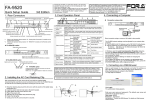
User’s Manual
Version 1.60 - July 2010
Offside Line and Live Tools
Epsio Version 1.60 – User’s Manual
EVS Broadcast Equipment – July 2010
Issue 1.60.C
C OPYRIGHT
EVS Broadcast Equipment – Copyright © 2010. All rights reserved.
D ISCLAIMER
The information in this manual is furnished for inform ational use only and subject
to change without notice. While every effort has been made to ensure that the
information contained in this user manual is accurate, up-to-date and reliable,
EVS Broadcast Equipment cannot be held responsible for inaccuracies or errors
that may appear in this publication.
I MPROVEMENT R EQUESTS
Your comments will help us improve the quality of the user documentation. Do not
hesitate to send improvement requests, or report any error or inaccuracy on this
user manual by e-mail to [email protected].
R EGIONAL C ONTACTS
The address and phone number of the EVS headquarters are mentioned in the
Help > About menu in the user interface.
You will find the full list of addresses and phone numbers of local offices on the
EVS website, on the following page:
http://www.evs.tv/Europe,+Middle+East+Africa/English/Contact-us/ContactUs/Regional-contacts-new-/page.aspx/2038
U SER M ANUALS ON EVS W EBSITE
The latest version of the user manual, if any, and other user manuals on EVS
products can be found on the EVS download center, on the following webpage:
http://www.evs.tv/Europe,+Middle+East+Africa/English/Downloadcenter/page.aspx/1887
I
Issue 1.60.C
II
Epsio Version 1.60 – User’s Manual
EVS Broadcast Equipment - July 2010
Epsio Version 1.60 – User’s Manual
EVS Broadcast Equipment – July 2010
Issue 1.60.C
Table of Contents
TABLE OF CONTENTS ................................................................................................... III WHAT’S NEW.................................................................................................................... 1 1. OVERVIEW ............................................................................................................... 2 1.1 PRODUCT DESCRIPTION ..........................................................................................................2 1.2 CABLING .....................................................................................................................................2 1.3 EPSIO USER INTERFACE ..........................................................................................................4 1.3.1 Overview .................................................................................................................................4 1.3.2 Operating Monitor ...................................................................................................................5 1.3.3 Server Information Area ..........................................................................................................5 1.3.4 Camera Angle List...................................................................................................................6 1.3.5 Zoom .......................................................................................................................................6 1.3.6 Tabbed Area ...........................................................................................................................6 2. CONFIGURATION .................................................................................................... 7 2.1 OVERVIEW ..................................................................................................................................7 2.1.1 Connection Steps ....................................................................................................................7 2.1.2 Configuration Steps.................................................................................................................7 2.1.3 Saving and Managing the Configuration .................................................................................8 2.2 CONNECTING EPSIO AND EVS SERVER .................................................................................9 2.2.1 Starting the EVS Server Application........................................................................................9 2.2.2 Epsio Settings on Remote Panel.............................................................................................9 2.2.3 Activating the Connection Between Epsio and the EVS Server ............................................10 2.2.4 Checking the Video Feeds ....................................................................................................10 2.3 CALIBRATING THE CAMERAS ................................................................................................12 2.3.1 Introduction ...........................................................................................................................12 2.3.2 Calibration Tab ......................................................................................................................12 2.3.3 How to Calibrate the Cameras ..............................................................................................18 2.3.4 Good Snapshots of the Playfield ...........................................................................................20 2.3.5 Recommendations for Matching the Virtual Playfield to the Real One ..................................23 2.3.6 Testing your Calibration ........................................................................................................24 2.3.7 Adding Virtual Points .............................................................................................................27 2.4 CONFIGURING THE CHROMA KEY.........................................................................................28 2.4.1 General Information ..............................................................................................................28 2.4.2 Accessing the Chroma Key Menus .......................................................................................29 2.4.3 Chroma Key Parameters.......................................................................................................31 2.4.4 Chroma Key Edit Screen on the Remote Panel ....................................................................33 2.4.5 Chroma Key Tab in Epsio .....................................................................................................34 2.4.6 Methods and Recommendations for the Chroma Key Definition ...........................................36 2.4.7 How to Configure a Chroma Key Based on an Automatic Chroma Key ................................37 2.4.8 How to Configure a Chroma Key Based on an Area Selected on the Playfield .....................38
III
Issue 1.60.C
Epsio Version 1.60 – User’s Manual
EVS Broadcast Equipment - July 2010
2.5 ADDING AND CUSTOMIZING THE GRAPHIC SUITE ..............................................................39 2.5.1 Graphic Suite Definition and Components ............................................................................39 2.5.2 Tools Tab ..............................................................................................................................40 2.5.3 How to Create a Graphic Suite .............................................................................................44 2.6 DEFINING THE REPLAY SETTINGS ........................................................................................45 3. CREATING GRAPHIC ANIMATIONS .................................................................... 47 3.1 GENERAL INFORMATION ........................................................................................................47 3.1.1 Prerequisites .........................................................................................................................47 3.1.2 Overview on the Epsio Menu ................................................................................................47 3.2 CREATING AN OFFSIDE ANIMATION .....................................................................................49 3.2.1 Remote Menu with Offside Feature Active ............................................................................49 3.2.2 How to Validate the Playfield Limits ......................................................................................49 3.2.3 How to Create an Offside Line Animation .............................................................................50 3.3 CREATING A LIVE ANIMATION ................................................................................................51 3.3.1 Remote Menu with a Live Tool Active ...................................................................................51 3.3.2 How to Create An Arrow or Circle Animation ........................................................................51 3.3.3 Using the Graphics Tool in Epsio ..........................................................................................52 IV
Epsio Version 1.60 – User’s Manual
Issue 1.60.C
EVS Broadcast Equipment – July 2010
What’s New
The following table describes the sections updated to reflect the new and modified
features on Epsio 1.60 (compared to Epsio 1.58).
has been added on left margin to highlight
In the user manual, the icon
information on new and updated features.
Click the section number (or the description) in the table to jump directly to the
corresponding section.
Section
Description
Section 1.2
Camera for live tools directly connected to IN2 of Epsio
Section 1.3.3
Server Information updated
Section 2.2.2
Default Tool setting on page 9.2 (F5) of the setup menu
on the Remote Panel
Section 2.2.4
Epsio Configurator: New user interface
Section 2.3.1
New preset main camera for calibrating the camera used
for live tools
Section 2.4.4
‘Save’ and ‘Save As’ commands in the Chroma Key Edit
screen on the Remote Panel
Section 2.5
Definition and customization of the graphic suite
Section 2.6
Distinct duration for Fade In and Fade Out in Replay
settings
Section 3.1.2
Modifications in the Epsio main menu, and new Epsio
secondary menu, further to live tool integration.
Section 3.3
Creation of an animation with a live tool
1
Issue 1.60.C
Epsio Version 1.60 – User’s Manual
EVS Broadcast Equipment - July 2010
1. Overview
1.1
PRODUCT DESCRIPTION
Epsio is a graphics solution integrated into the MulticamLSM that allows the
operators to control graphic animations, such as offside line, graphic overlays,
arrows or circles, using the LSM Remote Panel.
It can be used with the EVS XT family servers and works with Multicam, from
version 10.2.30 onwards.
Before the event, the user performs the initial calibration, where the images of the
playfield are matched with predefined angles into the system . Based on this
calibration, Epsio is able to instantly and automatically recognize the playfield
during actions when the playfield is clearly visible on the video signal. The user
will also define the chroma key, which means the range of colors on the video
signal where the graphic animations will be incrusted.
The operator can then trigger the animation in a one-second operation, using the
jog wheel of the LSM Remote Panel.
The producer can automatically see a screenshot with the graphic animation, and
decide whether or not to play out the entire action with the effects.
Important
If you want to use the live tools in Epsio, you need to have the Live
Tools license installed in XSecure.
1.2
CABLING
The schema on the following page shows how the Epsio workstation and the EVS
server BNC cables should be connected:
2
Epsio Version 1.60 – User’s Manual
EVS Broadcast Equipment – July 2010
Issue 1.60.C
3
Issue 1.60.C
Epsio Version 1.60 – User’s Manual
EVS Broadcast Equipment - July 2010
1.3
EPSIO USER INTERFACE
1.3.1
OVERVIEW
You will access Epsio by clicking the Epsio icon on the desktop, or via the Start
menu in Program Files > EVS Broadcast Equipment > Epsio > Epsio .
The following screenshot provides an overview on the Epsio user interface,
highlighting the various areas that will be explained in more details in the various
sections:
For more information on the LSM Remote Panel, refer to the Multicam Operational
User Manual.
4
Epsio Version 1.60 – User’s Manual
Issue 1.60.C
EVS Broadcast Equipment – July 2010
Note
When the offside line mode is activated on the LSM Remote Panel, you
cannot use the mouse outside the operating monitor in Epsio.
To be able to move the mouse in the whole Epsio window, do one of the
following:
• In Epsio, press
on the keyboard.
• Press RECORD on the LSM Remote Panel to go out of the offside line
mode.
1.3.2
OPERATING MONITOR
The operating monitor shows the video signal coming from the EVS server and
received on the Epsio connector IN1. It allows the users to visualize the
configuration action they perform, or the animations they create.
The im age on the monitor is surrounded by a colored fram e, which varies
depending on the tab open in the tabbed area on the right of the Epsio main
window:
• Blue frame when the Calibration tab is open
• Red frame when the Tools tab is open
• Green frame when the Chroma tab is open
1.3.3
SERVER INFORMATION AREA
The Server Information area is located at the left bottom of the Epsio main window
and provides the following information:
The 1 s t line specifies:
• The video standard used by Epsio and the EVS server
• The Epsio IN connector that receives the video signal from the EVS server.
The 2 n d line specifies:
• The Epsio and EVS server IP addresses
• The time when the last command was executed on the server.
When both system s are correctly connected, the icons in front of the first two lines
are greens.
The 3 r d line informs the user whether the animation is visible or not.
5
Issue 1.60.C
1.3.4
Epsio Version 1.60 – User’s Manual
EVS Broadcast Equipment - July 2010
CAMERA ANGLE LIST
The Camera Angle list shows a thum bnail for each camera angle that has been
defined and/or calibrated. You can select a camera angle by clicking the
thumbnail. This Camera Angle list is particularly useful in the Calibration phase.
When the camera angle has only been created, but not calibrated yet, the
thumbnail shows a grey background and the virtual playfield.
When the camera angle has been calibrated, the thumbnail shows the frame
grabbed from the video signal.
1.3.5
ZOOM
The zoom area shows a zoomed display of the area around the mouse pointer on
the operating monitor. It mainly allows performing the calibration, as well as other
actions, in a very précised way.
1.3.6
TABBED AREA
The tabbed area gives access to the following tabs, in which you can configure
Epsio and select the animations you will perform:
• The CALIB tab allows the users to define and calibrate the camera angles.
See also the section 2.3.2 ‘Calibration Tab’, on page 12.
• The TOOLS tab allows the users to select the animations they want to perform,
and refine the settings for these animations.
See also the section 2.5.2 ‘Tools Tab’, on page 40
• The CHROMA tab allows the users to define the chroma key layer that will
define how the offside line animation will be displayed.
See also the section 2.4.5 ‘Chroma Key Tab in Epsio’, on page 34.
6
Epsio Version 1.60 – User’s Manual
Issue 1.60.C
EVS Broadcast Equipment – July 2010
2. Configuration
2.1
OVERVIEW
The configuration in order to use Epsio with an EVS server has to be performed in
the Epsio application or on the EVS server side (via the EVS menu and the LSM
Remote Panel), depending on the configuration step.
2.1.1
CONNECTION STEPS
Before you can actually configure Epsio, you first need to set up Epsio and the
EVS server to communicate with each other:
2.1.2
#
Step
Where?
See section
1.
Starting the appropriate EVS server
application
EVS server
2.2.1
2.
Activating the connection between
Epsio and the EVS server
Remote Panel
2.2.3
3.
Checking the video feeds
Epsio
2.2.4
CONFIGURATION STEPS
Once Epsio and the EVS server are properly connected, you can perform the
actual configuration steps.
#
Step
Where?
See section
1.
Calibrating the cameras
Epsio
2.3
2.
Configuring the Chroma Key settings
Remote Panel
or Epsio
2.4
3.
Customizing and loading the graphic
suite
Epsio
2.5
4.
Defining the Replay settings
Remote Panel
2.6
7
Issue 1.60.C
2.1.3
Epsio Version 1.60 – User’s Manual
EVS Broadcast Equipment - July 2010
SAVING AND MANAGING THE CONFIGURATION
The commands available in the the File menu allow you to save and manage the
configuration you will perform. The configuration, which includes the camera
calibration and the chroma key definition, is saved in a configuration file that is
made up of two .xml files:
• A file containing the playfield distances and all camera angle definitions.
This file is ‘name’.xml where <name> is the name the user gives to the
configuration when it is saved for the first time.
• A file containing the chroma key configuration.
This file is ‘name’.CK.
In the File menu, you have access to the following commands:
Command
Use
New
Use this command before you start a new calibration.
This creates a new em pty configuration file that you can save
throughout the calibration process.
Load
Use this command to point to and load an existing configuration file.
Save
Use this command to save your calibration while you define it.
It is recommended to save the configuration after each calibration
step.
Save As
Use this command if you want to save the open configuration file
into a new name, for backup purposes, or to start a new calibration
from an existing one.
The configurations are stored by default in the following location:
C:/Program Files/EVS Broadcast Equipment / Epsio/Config.
8
Epsio Version 1.60 – User’s Manual
Issue 1.60.C
EVS Broadcast Equipment – July 2010
2.2
CONNECTING EPSIO AND EVS SERVER
2.2.1
STARTING THE EVS SERVER APPLICATION
When using Epsio with an EVS server, you need to run a server application:
• with at least 2 recorder channels and 2 player channels
• in a Multicam LSM base configuration.
For more information on starting an EVS application, refer to the EVS Menu
section in the Technical Reference Software manual.
2.2.2
EPSIO SETTINGS ON REMOTE PANEL
The settings to activate the Epsio mode, and specify the default Epsio tool are
available on page 9.2 of the Setup menu. These settings are described below:
Setting
Possible
Values
Description
[F2] Offside
Line
On, Off
(default)
Activates the offside line feature, whatever
internal or external.
When the parameter is set to ‘On’, the External
Offside param eter is displayed.
[F3] External
Offside
On, Off
(default)
Enables the control of Epsio from the Remote
Panel.
When the setting is set to ‘Off’, the offside line
feature built in the EVS server is active. The
SHIFT+D key in the Operational menu gives
access to the Offside menu.
When the setting is set to ‘On’, the Epsio
application is active. The SHIFT+D key in the
Operational menu gives access to the Epsio
menu. The IP Address and Default Tool
parameters are displayed.
The EVS server will set this setting to ‘On’ if no
telestration option is installed on the server.
[F4] IP
Address
xxx.xxx.xxx.xxx
When the Epsio connection is enabled with the
External Offside parameter, the IP Address of
the Epsio workstation has to be entered in this
parameter to allow the communication between
the EVS server and the Epsio workstation.
[F5] Default
Tool
Offisde, Arrow,
Circle,
Graphics
When the Epsio connection is enabled with the
External Offside parameter, this parameter
specifies the tool to be activated by default in
the Epsio menu on the Remote Panel.
9
Issue 1.60.C
2.2.3
Epsio Version 1.60 – User’s Manual
EVS Broadcast Equipment - July 2010
ACTIVATING THE CONNECTION BETWEEN EPSIO AND THE
EVS SERVER
To activate the offside line mode and the external offside line mode, proceed as
follows:
1. From the Main menu, select Setup by pressing SHIFT + D to enter the Setup
menu.
2. Press the F9 key to go to the Special Effects settings, and then F0 to open
page 9.2.
3. Press F2 to access the Offside Line setting and rotate the jog dial to set it to
‘ON’.
This will display the External Offside setting.
4. Press F3 to access the External Offside setting and rotate the job dial to set
it to ‘ON’. The EVS server will set this setting to ‘On’ if no telestration option
is installed on the server.
This will display the IP Address setting.
5. Enter the IP address of the Epsio workstation as follows:
After entering the number for an octet with the function keys, validate by
pressing ENTER on the LSM Remote Panel.
6. Press MENU twice to go out of the Setup menu.
7. Press SHIFT+D to enter the offside line mode.
The Epsio workstation should now be connected. In Epsio, the first tw o lines in the
Server Information area should have green icons, which shows that both systems
are correctly connected and using the same standard:
For more information on this Server Information area, refer to the section 1.3.3
‘Server Information Area’, on page 5.
2.2.4
CHECKING THE VIDEO FEEDS
Once you have switched on the Epsio workstation for an event, you should check
that you correctly get the feeds before you launch the Epsio software. The Epsio
Configurator helps you detect and check the feeds.
To check the video feeds, proceed as follows:
1. Double
click
EpsioConfigurator.exe
available
in
C:/Program
Files/EVS Broadcast Equipment/Epsio/Bin or on the desktop.
The Epsio Configurator opens:
10
Epsio Version 1.60 – User’s Manual
EVS Broadcast Equipment – July 2010
Issue 1.60.C
2. In the Setup group box, select the Video Format you are working with and the
type of Genlock system you are using.
3. Click the Open button.
Epsio checks the format you have specified is compatible with the format used
by the EVS server.
Epsio automatically grabs and displays an image of the video signals delivered
to the IN connectors and sent from the OUT connectors.
4. As you check the incoming and outgoing signals, you can perform the following
actions to help you identify the signals:
o
To check the incoming signals, you can click the Grab button to grab the
current image delivered to the incoming feeds.
o
To check the output signal from the OUT1 connector, you can either
change the signal sent to OUT1 by selecting In 1, In 2, or Bars, or add the
PC time or a logo display to the output signal.
o
To check the current output signal from the OUT 2 connector, you can click
the Snap button to refresh the video display corresponding to output 2.
5. When you have checked the incoming and outgoing video signals, click the
Apply button.
6. Click Exit.
11
Issue 1.60.C
Epsio Version 1.60 – User’s Manual
EVS Broadcast Equipment - July 2010
2.3
CALIBRATING THE CAMERAS
2.3.1
INTRODUCTION
In Epsio, calibrating the cameras consists of positioning a virtual playfield in a 3D
environment to match the position of the actual playfield used for a given event.
You calibrate the cameras in the Calibration tab in Epsio.
O FFSIDE L INE C ALIBRATION
When you use the offside line tool, you usually calibrate tw o 16-meter cameras for
an event: a left-angle camera and a right-angle camera. However, Epsio allows
you to use other cameras.
You calibrate each 16-meter camera on two angles: looking at the goad area, and
at the central circle.
L IVE T OOLS C ALIBRATION
When you use the live tools, you calibrate the camera that is directly connected to
Epsio via the IN2 Connector. For this physical camera, you will calibrate a main
camera in Epsio. The three angles (left, center and right) are automatically added
to the Camera Angle List when you add a main camera in the Calibration tab.
Important
Only calibrate your cameras when you have validated the camera
position, height and orientation. These should no longer change after the
calibration.
2.3.2
CALIBRATION TAB
O VERVIEW
The following table gives a short explanation on each area of the Calibration tab
displayed below:
Area
Description
Camera Creation
This area allows you to add cameras, and assign them to a
recorder channel on an EVS server.
See also the section ‘Camera Creation Area’, on page 14.
Current Camera
This area allows you to perform several actions on the
selected camera.
See also the section ‘Current Camera Area’, on page 15.
12
Epsio Version 1.60 – User’s Manual
Issue 1.60.C
EVS Broadcast Equipment – July 2010
Area
Description
General
This area allows you to modify the default playfield size (105
meters by 68 meters), as well as to display and/or modify
the grid of the virtual playfield.
See also ‘General Area’, on page 17.
13
Issue 1.60.C
Epsio Version 1.60 – User’s Manual
EVS Broadcast Equipment - July 2010
C AMERA C REATION A REA
This area allows you to add cameras, and assign them to a recorder channel on an
EVS server.
Field
Description
Buttons that allow the user to define a new camera in
the system. Several preset cameras are available:
• The Add button below the 16 Left label allows
adding a 16-meter left-angle camera.
It creates two cameras angles (goal and center).
• The Add button below the 16 Right label allows
adding a 16-meter right-angle camera.
It creates two cameras angles (goal and center).
• The Add button below the Main Label allows adding
a camera for the live tools.
It creates three camera angles (left, center, right).
• The Add button below the Free Preset label should
be used to create any other camera.
It creates one camera angle.
Field to associate the recorder channel of the EVS
server to the created camera. The field value is made
up as follows:
• The first letter is the camera letter on the server
• The last two digits correspond to the server net
number on the SDTI network.
By default, the A channel is assigned to the 16-meter
left camera, and the B channel is assigned to the to the
16-meter right camera.
14
Epsio Version 1.60 – User’s Manual
Issue 1.60.C
EVS Broadcast Equipment – July 2010
C URRENT C AMERA A REA
This area allows you to perform several actions on the current camera. The
current camera is the one selected in the Camera Angle list. This is displayed in a
blue frame in the Camera Angle list.
Field
Description
Displays the name of the camera selected in
the Camera Angle list below the operating
monitor.
The camera name can only be modified using
the Rename button.
Rename button used to rename the camera.
Non-editable field that summarizes the
parameters for the camera position.
Non-editable field that summarizes the
parameters for the camera orientation.
Check box that allows the system to detect the
goal area when the user creates an offside line
animation. When you calibrate a left or right
angle, tick this check box.
For the automatic detection to work properly,
the image should clearly display the goal area.
15
Issue 1.60.C
Epsio Version 1.60 – User’s Manual
EVS Broadcast Equipment - July 2010
Field
Description
Check box that allows the system to detect the
central circle when the user creates an offside
line anim ation. When you calibrate a center
camera angle, tick this check box.
For the automatic detection to work properly,
the image should clearly display the central
circle.
Snap Button used to grab a new image of the
playfield on which the calibration of the camera
will be based. It grabs the current frame on the
video input 1 (PGM1).
Button used to reinitialize the display of the
virtual playfield for the selected camera.
Button used to delete the selected camera.
Check box to display or hide the two fields
below used for fine-tuning the current camera
position.
Field that allows selecting the position
parameter you want to modify among the
following ones:
• X axis: north/south axis to define the camera
position
• Y axis: east/west axis to define the camera
position
• Z axis: up/down axis to define the camera
position
• Pan: angle to define the horizontal
orientation of the camera on its position, in
this case from 85° to 125°
• Tilt: angle to define the vertical orientation
of the camera on its position, in this case
from 60° to 100°.
• Roll: angle to define the camera orientation
along its longitudinal axis, in this case from 20 to +20°
• Orientation: mix of Y axis and pan, to
simulate a rotation around the center of the
playfield
Once the position parameter is selected, you
can change its value dragging the slider to the
right or left.
16
Epsio Version 1.60 – User’s Manual
Issue 1.60.C
EVS Broadcast Equipment – July 2010
G ENERAL A REA
This area allows you to modify the size of the virtual playfield, and whether/how
grids will be displayed on the virtual playfield.
Field
Description
Length
Slider to modify the default playfield length (105 meters).
Width
Slider to modify the default playfield length (68 meters).
Show Grid
Check box to display or hide the grid on the virtual playfield
Space
When the grid is displayed, the space slider makes it possible
to modify the line space in the grid.
17
Issue 1.60.C
2.3.3
Epsio Version 1.60 – User’s Manual
EVS Broadcast Equipment - July 2010
HOW TO CALIBRATE THE CAMERAS
Note
The calibration steps explained in the sections below illustrate the
calibration of the two 16-meter cameras used with the offside line tool.
However, the same procedure applies to the calibration of the free
camera for the live tools.
Once Epsio is open, you calibrate the various cameras in the CALIB tab, in the
following way:
1.
Add a virtual camera for each physical camera to be calibrated, by clicking
the Add button corresponding to the requested camera in the Creation area:
The camera angles to be calibrated for the corresponding camera preset are
added as fram es including the virtual playfield in the Camera Angle list:
2.
Using the Preview channel, make snapshots of the
corresponding to each calibration angle in the following way:
real
playfield
a. In the Camera Angle list in Epsio, click the camera angle to which you
want to associate a snapshot.
b. Pause on the requested frame in the preview channel.
18
Epsio Version 1.60 – User’s Manual
Issue 1.60.C
EVS Broadcast Equipment – July 2010
c. Click
in the Current area in Epsio.
For more information, refer to the section 2.3.4 ‘Good Snapshots of the
Playfield’, on page 20.
3.
For each camera angle, perform a rough calibration, by matching four noncontiguous virtual anchor points to the real position in the playfield as
follows:
• Right-click a virtual anchor point (crosses on the lines) on the requested
camera angle and drag it to the corresponding position on the real
playfield, then release.
A light blue line is drawn between the virtual point and the matched point on
the snapshot:
Once the fourth point has been matched, the virtual playfield is automatically
superimposed to the snapshot.
For more information on the four points to be matched, and on the possible
actions with the mouse, refer to the section 2.3.5 ‘Recommendations for
Matching the Virtual Playfield to the Real One’, on page 23.
4.
Adjust the playfield size if necessary:
• Check that touchlines are not too long or too sm all on the four calibration
angles, and if necessary adjust the playfield width.
• Check that the central circle is not too large or small on the two central
calibration angles, and it necessary adjust the playfield length.
5.
Click the menu File > Save to save the configuration. The default location
where
configurations
are
stored
is
C:/Program
Files/
EVS Broadcast Equipment/Epsio/Config.
The camera angles defined in Epsio are now associated to snapshots of the
real playfield and saved in a configuration file. You can load them back via
the File > Load menu. See also the section 2.1.3 ‘Saving and Managing the
Configuration’, on page 8.
19
Issue 1.60.C
Epsio Version 1.60 – User’s Manual
EVS Broadcast Equipment - July 2010
6.
Load the test snapshots, and perform the necessary adjustments, by
repositioning only the anchor points initially matched in step 3.
For more information on the calibration tests, see the section 2.3.6 ‘Testing
your Calibration’, on page 24.
7.
On a shot that includes the 16-m eter line, and part of the central circle, add
virtual points for offside shots where playfield lines would not be visible.
For more information on additional virtual points, see the section 2.3.7
‘Adding Virtual Points’, on page 27.
2.3.4
GOOD SNAPSHOTS OF THE PLAYFIELD
I NTRODUCTION
For each 16-meter camera used for the offside feature, you need to take two
snapshots corresponding to each camera angle:
• Goal area
• Central circle
For the main camera used for the live tools, you need to take three snapshots
corresponding to each camera angle:
• Left angle
• Center angle
• Right angle
Keep the following in mind when you select the frame you will use:
• A playfield is naturally curved, whereas the Epsio virtual field is made up of
straight lines.
• A very wide shot is very likely to distort the image, which will intensify the
curved effect of the field.
20
Epsio Version 1.60 – User’s Manual
EVS Broadcast Equipment – July 2010
Issue 1.60.C
S NAPSHOTS FOR THE G OAL A REA C ALIBRATION
The snapshot for the goal area of the left or right 16-meter camera should show:
• the whole left or right penalty area (respectively) with 16-meter line, including
the goal area with the 6-meter line
• the goal line along the goal area,
• part of each touchline on both sides of the playfield.
Important
The touchlines should be parallel to the horizontal borders of the frame,
and the zoom should keep the distortions of touchlines as low as
possible.
Figure 1: Good Snapshot for the calibration of the goal area with a left 16-meter camera
Figure 2: Good Snapshot for the calibration of the goal area with a right 16-meter camera
21
Issue 1.60.C
Epsio Version 1.60 – User’s Manual
EVS Broadcast Equipment - July 2010
S NAPSHOTS FOR THE C ENTRAL C IRCLE C ALIBRATION
The snapshot for the central circle of the left or right 16-meter camera should
show:
• the whole central circle (not the full central line),
• the 16-meter line of the left or right penalty area (respectively), and the penalty
arc.
• part of each touchline on both sides of the playfield.
Figure 3: Good Snapshot for the calibration of the central circle with a left 16-meter camera
Figure 4: Good Snapshot for the calibration of the central circle with a right 16-meter camera
22
Epsio Version 1.60 – User’s Manual
EVS Broadcast Equipment – July 2010
2.3.5
Issue 1.60.C
RECOMMENDATIONS FOR MATCHING THE VIRTUAL
PLAYFIELD TO THE REAL ONE
V IRTUAL P OINTS TO BE M ATCHED FOR E ACH C AMERA A NGLE
The following screenshots show four virtual points you are advised to use for each
camera angle to perform an optimal calibration:
Goal Area
Central circle
P OSSIBLE A CTIONS U SING THE M OUSE
Here are the possible actions you can perform in this step:
• To select a virtual point, right-click on it.
• To delete a virtual point, click on it.
• To add a virtual point, press CTRL + click on the virtual field at the position
where the point should be added.
• To remove a virtual point you have added, click on it.
23
Issue 1.60.C
Epsio Version 1.60 – User’s Manual
EVS Broadcast Equipment - July 2010
A DDITIONAL T IPS
Here are the following tips to help you in this step:
• Once you have selected a virtual point, you can adjust its position using the
arrows on your keyboard.
• The four anchor points you use to calibrate a camera angle should not be
aligned.
• Always match the points to the same edge of the lines.
• You can use more than 4 points to perform the calibration.
• If the 2 n d and 3 r d tests of the goal area calibration for a given camera are
excellent, you can use the position parameters (x,y,z) of this camera angle for
the central circle calibration of the same camera.
2.3.6
TESTING YOUR CALIBRATION
G ENERAL T EST
Once you have calibrated all your camera angles, it is recommended to test them
using test snapshots of the playfield.
A general and quick test consists of drawing an offside line, and rolling it over the
calibration shots, to ensure that the offside line matches the following lines of the
field:
• the 16-meter line
• the 6-meter line
• the half-way line
Systematic tests based on test snapshots are explained in details below.
T ESTING THE G OAL A REA
1 s t Test
Using the same view as your calibration shot, take an offside shot.
Check that the 16-meter line and 6-meter line are correctly matched.
If necessary, reposition the faulty anchor points.
24
Epsio Version 1.60 – User’s Manual
EVS Broadcast Equipment – July 2010
Issue 1.60.C
2 n d test
Move the camera to the bottom corner arch without changing the zoom.
Check that the 16-meter line and 6-meter line are correctly matched.
3 r d test
Move the camera back to the goal area, keeping the 6-meter and 16-meter lines.
All lines must match.
If the tests are not satisfactory, refine the calibration by matching several
calibration points again. Each time you modify your calibration, you need to
perform the tests again.
When you do not achieve perfect results using calibration points, you can modif y
the advanced settings for the camera position in the Current area to fine-tune your
calibration. These parameters allow a global modification of the calibration for
each camera, taking into account the X, Y, Z position, as well as the orientation
with the pan, tilt and roll angles. See also the description of the Advanced group
box in the section ‘Current Camera Area’, on page 15.
25
Issue 1.60.C
Epsio Version 1.60 – User’s Manual
EVS Broadcast Equipment - July 2010
T ESTING THE C ENTRAL CIRCLE
All lines must be correctly matched on the calibration shot. Besides this, you
should test three additional test shots:
1 s t test
Using the same view as your calibration shot.
Check that the central circle is correctly matched, and that the borders of the halfway line are correctly matched.
If necessary, reposition the faulty anchor points.
2 n d test
Center the camera on the half-way line to see the whole line.
When you draw an offside line on this shot, the virtual line should touch both ends
of the half-way line. Due to the natural playfield curve, the offside line may not
fully correspond to the half-way line around the middle of the line.
26
Epsio Version 1.60 – User’s Manual
EVS Broadcast Equipment – July 2010
Issue 1.60.C
3 r d test
Move and zoom the camera to view the 6-meter line, and part of the half-way line.
Use this test shot to add your additional virtual points.
2.3.7
ADDING VIRTUAL POINTS
During the calibration, it is recommended to create additional virtual points
outside the playfield, using the stadium geom etry (first step of the terracing, static
banners around the field, and so on).
To add virtual points, you can use a shot similar to the snapshot used for the 3 r d
calibration test of the central circle.
The additional virtual points will be used later on if you have to manually
reposition your virtual playfield to validate the field limits (See the section 3.2.2
‘How to Validate the Playfield Limits’, on page 49) with shots where no playfield
lines are displayed, such as the following one:
27
Issue 1.60.C
Epsio Version 1.60 – User’s Manual
EVS Broadcast Equipment - July 2010
2.4
CONFIGURING THE CHROMA KEY
2.4.1
GENERAL INFORMATION
C ONCEPT OF C HROMA K EY
The chroma keying is a technique for compositing two images or fram es together
in which a color (or a range of colors) from the main image (video signal) is
removed (or made transparent), revealing another im age behind it. The key is the
image that punctures through the image of the video signal.
In Epsio, you select the green color of the playfield (or a range of green) and
replace it by the key layer. The key layer will define how the offside line animation
will be displayed:
• All that is white in the key layer will not be incrusted.
In the final result, the key is transparent and the main image will show.
• All that is black in the key layer will be incrusted with the offside line animation.
In the final result, the main image is covered by the offside line anim ation.
• The more an area is black, the more the incrusted material will show.
In summary, when you define the chroma key, you define the color or color range
in the video signal that will be replaced by the offside line anim ation.
28
Epsio Version 1.60 – User’s Manual
Issue 1.60.C
EVS Broadcast Equipment – July 2010
I MPACT OF L IGHT C ONDITIONS
As the chroma key depends on the light, it is recommended to configure the
chroma key 30 minutes before the match to get the closest to the light conditions
that will prevail during the match.
For a match during the day, you should perform two chroma key configurations:
one for light, one for dark, to allow you to cope with shadows on the playfield.
In case you have a bright light, but a large shadow across the field (for example
the top of the stadium roof structure), you can also make a chroma key matching
light and shadows, in which case the players would be under the graphics.
For a match during the night, you can configure a chroma key as soon as the sun
is down and the stadium lights are on.
R ECOMMENDATIONS
You can define the chroma key:
• in the chroma key edit screen on the LSM Remote Panel
• in the CHROMA tag in Epsio.
It is recommended to configure the chroma key using the Remote Panel. For this
reason, we will provide minimal information on the chroma key definition using the
CHROMA tab in Epsio.
2.4.2
ACCESSING THE CHROMA KEY MENUS
O N THE LSM R EMOTE P ANEL
To access the Chroma Key edit screen on the LSM Remote Panel, proceed as
follows:
1. From the operational menu in PGM/PRV mode, press the SHIFT+D key to enter
the Epsio main menu:
Rst Cam
Local
Cam A
Cam B
Sync Prv
Epsio
The Offside menu opens:
ChromaK
Graph
OSD
<--Calib
Calib -->
2. In the Epsio menu, press SHIFT+B to enter the Chroma Key edit screen.
Chroma key
F1: X
F2: Y
F3: Width
F4: Height
Auto
Profile 1
Save
Server
Edit Screen
F5: X Transition
F6: Y Transition
F7: Black Level
F8: Toggle View
Save As
Quit
Profile 2
Profile 3
Profile 4
You will configure the chroma key from this menu.
29
Issue 1.60.C
Epsio Version 1.60 – User’s Manual
EVS Broadcast Equipment - July 2010
I N E PSIO
In Epsio, you can configure the chroma key in the CHROMA tab:
30
Epsio Version 1.60 – User’s Manual
EVS Broadcast Equipment – July 2010
2.4.3
Issue 1.60.C
CHROMA KEY PARAMETERS
You can create and manage up to four chroma key definitions from the LSM
Remote Panel, or in Epsio, using the chroma key profiles.
The various chroma key parameters allow you to define or refine a chroma key
profile.
The representation of the chroma key definition in a color space will help you
visualize the range of colors taken into account in the chroma key definition.
R EPRESENTATION OF THE C HROMA K EY IN E PSIO
A YUV color space is displayed on the CHROMA tab in Epsio to represent the
color range selected in the chroma key:
The chroma key definition is represented as follows on the color space:
• The black box in the color space corresponds to the colors that are totally
removed on the chroma key layer (black).
• The colors between the black and white boxes in the color space correspond to
the transition color range, in other words to the colors that will be more or less
removed on the chroma key layer. The white box is clearly displayed in Epsio.
• The colors outside the white box in the color space correspond to the colors
that are not removed on the chroma key layer (white).
R EPRESENTATION OF THE C HROMA K EY ON THE M ONITOR
A YUV color space is displayed on the top left corner of the monitor to represent
the color range selected in the chroma key. It contains additional scales, with
‘sliders’ to reflect the hue, saturation and black level (or brightness) of the
selected color range. The grey box displayed on the color space represents the
selected color range.
31
Issue 1.60.C
Epsio Version 1.60 – User’s Manual
EVS Broadcast Equipment - July 2010
D EFINITION OF THE C HROMA K EY P ARAMETERS
The chroma key parameters are explained in the table below:
Parameter
Description
RGB Hue Value Definition
X
Moves left and right the color range in the color space.
Y
Moves up and down the color range in the color space.
Tolerance Definition
Width (W)
Widens or narrows the color range on the X axis in the
space.
Height (H)
Widens or narrows the color range on the Y axis in the
space.
Transition Definition
32
X Transition (TX)
Widens or narrows (on the X axis) the color range that will
be more or less punctured when defining the key layer.
Y Transition (TY)
Widens or narrows (on the Y axis) the color range that will
be more or less punctured when defining the key layer.
Black Level
Adjusts the level of transparency of the graphic animation,
in other words defines how strong the animation will be
displayed.
Epsio Version 1.60 – User’s Manual
Issue 1.60.C
EVS Broadcast Equipment – July 2010
2.4.4
CHROMA KEY EDIT SCREEN ON THE REMOTE PANEL
I NTRODUCTION
You define and manage the chroma key definition from the Chroma Key edit
screen. When you are in this screen, the Edit mode is directly active.
Chroma key
F1: X
F2: Y
F3: Width
F4: Height
Auto
Profile 1
Save
Server
Edit Screen
F5: X Transition
F6: Y Transition
F7: Black Level
F8: Toggle View
Save As
Quit
Profile 2
Profile 3
Profile 4
In addition, the color space is also displayed at the top left of the operator’s PGM
monitor when you define the chroma key. It allows you to visualize the range of
colors taken into account in the chroma key definition.
For more information refer to the sections:
• Section ‘Available Commands’ (page 33)
• Section ‘Chroma Key Parameters’ (page 31)
• Section ‘How to Configure a Chroma Key Based on an Automatic Chroma Key’
(page 37)
• Section ‘How to Configure a Chroma Key Based on an Area Selected on the
Playfield (page 38)
A VAILABLE C OMMANDS
The following table describes the various commands and parameters available on
the chroma key edit screen on the Remote Panel:
Field area or button
Description
Chroma Key
Parameters (F1-F7)
Parameters to define the color range taken into account
in the chroma key definition.
For more information on the various parameters, refer the
section ‘Chroma Key Parameters’, on page 31.
Toggle View (F8)
Toggles between the key layer view (white & black), and
image view (color) on the operator’s PGM monitor.
Auto (SHIFT+A)
Press this key to perform an automatic chroma key
definition that you can then save in one of the available
profiles.
Save (SHIFT+B)
Press this key to save the changes into the currently
loaded profile (highlighted in black on the Chroma Key
edit screen.
33
Issue 1.60.C
2.4.5
Epsio Version 1.60 – User’s Manual
EVS Broadcast Equipment - July 2010
Field area or button
Description
Save As (SHIFT+C)
Press this key, followed by a key corresponding to a
chroma key profile to save the currently loaded chroma
key definition under the selected chroma key profile.
Quit (SHIFT+D)
Press this key to leave the chroma key edit screen.
Profile 1 (A) to Profile
4 (D)
Four profiles under which the chroma key definitions can
be saved.
CHROMA KEY TAB IN EPSIO
T AB O VERVIEW
You can also refine the chroma key definition in the CHROMA tab in Epsio.
The following schema shows the various areas in the CHROMA tab.
34
Epsio Version 1.60 – User’s Manual
Issue 1.60.C
EVS Broadcast Equipment – July 2010
F IELDS AND C OMMANDS IN THE CHROMA T AB
The following table describes the field boxes and buttons on the tab:
User Interface
Element
Description
Profiles area
EVS Profiles list
Lists the chroma key profiles available in the Chroma Key
edit screen of the LSM Remote Panel:
• Clicking the profile will load a preview of the chroma key
on the preview area.
• Double-clicking the profile will load the chroma key
parameters in the CHROMA tab and the chrom a key
definition for the current image of PGM1 if you are in the
Chroma Key edit screen on the LSM Remote Panel. This
image will show in the Epsio operating monitor.
Preview
Shows a preview of the chroma key profile selected in the
list.
Snap
Button used to snap the current image from PGM1 and
loads it onto the operating monitor.
Load
Button used to load the profile selected in the Settings
area.
Save
Button used to save the chroma key values defined for the
chroma key profile loaded into the CHROMA tab.
Settings area
Color space
Shows the color range for the chroma key definition.
Also refer to the section ‘Chroma Key Parameters’, on
page 31.
Adjustment sliders
Each slider allows modifying one of the chroma key
parameter of the loaded chroma key profile.
Also refer to the section ‘Chroma Key Parameters’, on
page 31.
Note
When you are refining the Chroma key in Epsio, you can toggle between
the chroma key and the image showing the final incrustation by rightclicking the mouse.
35
Issue 1.60.C
2.4.6
Epsio Version 1.60 – User’s Manual
EVS Broadcast Equipment - July 2010
METHODS AND RECOMMENDATIONS FOR THE CHROMA KEY
DEFINITION
M ETHODS
There are several ways to configure your chroma key.
This section will explain the two main methods:
• Defining a chroma key based on an autom atically generated chroma key.
• Defining a chroma key based on an area selected on a playfield.
S TEPS
In both methods, you need to go through the following steps:
1. Accessing the Chroma Key edit screen.
2. Generating the initial chroma key definition
3. Opening a chroma key profile (and load the initial chroma key)
4. Refining the initial chroma key definition
5. Saving the final chroma key definition in a profile.
R ECOMMENDATIONS AND T IPS
In the Chroma Key edit screen, the F8 function allows you to toggle between the
chroma key layer (white/black display) and the representation of the final
incrustation on the video signal (color display).
It is recommended to:
• Use the chroma key layer to define the chroma key parameters from F1 to F6.
• Toggle to the final incrustation to refine the black level parameter (F7).
Note
If you cannot see the representation of the final incrustation, this means
you need the limits of your playfield could not be automatically validated.
You need to validate them manually. See the section 3.2.2 ‘How to
Validate the Playfield Limits’, on page 49.
36
Epsio Version 1.60 – User’s Manual
Issue 1.60.C
EVS Broadcast Equipment – July 2010
2.4.7
HOW TO CONFIGURE A CHROMA KEY BASED ON AN
AUTOMATIC CHROMA KEY
The automatic chroma key is based the colors located within the virtual playfield.
For this reason, the virtual playfield must be correctly matched to the real
playfield on the snapshot you will use for the automatic chroma key.
To configure a chroma key based on an automatic chroma key, proceed as follows:
1. In the main operational menu, jog to an im age of the real playfield that you will
use for the chroma key configuration.
2. Press SHIFT+D to enter the Epsio menu.
3. If the virtual playfield is not correctly matched to the real playfield, do one of
the following:
o
Validate the field lim its as explained in the section 3.2.2 ‘How to Validate
the Playfield Limits’, on page 49.
o
Make an offside animation as explained in the section 3.2.3 ‘How to Create
an Offside Line Animation’, on page 50.
4. Press SHIFT+B to enter the Chroma Key edit screen.
Chroma key
F1: X
F2: Y
F3: Width
F4: Height
Auto
Profile 1
Save
Server
Edit Screen
F5: X Transition
F6: Y Transition
F7: Black Level
F8: Toggle View
Save As
Quit
Profile 2
Profile 3
Profile 4
5. Press SHIFT+A (Auto) to generate an automatic chroma key on which you will
base your chrom a key configuration.
6. Press SHIFT+C (Save As), then press A, B, C or D to select the profile in
which you want to save the automatic chroma key definition.
7. Press the key corresponding to the profile on which you have just saved the
automatic chroma key definition.
The automatic chroma key is loaded onto the operator’s preview monitor. You
can now refine it.
8. Press the function key corresponding to the parameter you want to modify and
jog the wheel to modify the parameter value as requested.
In this step, you can press F8 when you want to toggle between the key layer
and a representation of the final incrustation.
9. Repeat step 8 for all parameters you want to adjust.
10. Once you are satisfied with the chroma key definition, press SHIFT+C (Save
as), then press A , B, C or D to select the profile in which you want to save our
final chroma key definition.
11. Select the profile you want to use in your offside line animations. By default,
the last saved profile is active.
12. Press SHIFT+Q to quit and come back to the Epsio menu.
When you leave the Chroma Key edit screen, the activated profile is the one that
will be applied when you will create an offside line animation. The active profile is
displayed on a black background on the Chroma Key edit screen.
37
Issue 1.60.C
2.4.8
Epsio Version 1.60 – User’s Manual
EVS Broadcast Equipment - July 2010
HOW TO CONFIGURE A CHROMA KEY BASED ON AN AREA
SELECTED ON THE PLAYFIELD
To configure a chroma key based on an area selected on the Playfield, proceed as
follows:
1. In the main operational menu, jog to an im age of the real playfield that you will
use for the chroma key configuration.
2. Press SHIFT+D to enter the Epsio menu.
3. Press SHIFT+B to enter the Chroma Key edit screen.
Chroma key
F1: X
F2: Y
F3: Width
F4: Height
Auto
Profile 1
Save
Server
Edit Screen
F5: X Transition
F6: Y Transition
F7: Black Level
F8: Toggle View
Save As
Quit
Profile 2
Profile 3
Profile 4
4. Press A, B, C or D to select the profile on which you will configure your
chroma key.
5. Press F8 to display the video signal in color on the director’s preview.
6. Looking at the operator’s preview, draw a rectangle with the mouse on the
image of the playfield to select an area that contains the basis color for your
chroma key.
7. Press the function key corresponding to the parameter you want to modify and
jog the wheel to modify the parameter value as requested.
In this step, you can press F8 when you want to toggle between the key layer
(black and white), and the representation of the final incrustation.
8. Once you are satisfied with the chroma key definition, press SHIFT+C (Save
as), then press A, B, C or D to select the profile in which you want to save
your final chroma key definition.
9. Select the profile you want to use in your offside line animations.
10. Press SHIFT+Q to quit and come back to the Epsio menu.
When you leave the Chroma Key edit screen, the activated profile is the one that
will be applied when you will create an offside line animation. The active profile is
displayed on a black background on the Chroma Key edit screen.
38
Epsio Version 1.60 – User’s Manual
EVS Broadcast Equipment – July 2010
2.5
ADDING AND CUSTOMIZING THE
GRAPHIC SUITE
2.5.1
GRAPHIC SUITE DEFINITION AND COMPONENTS
Issue 1.60.C
The graphic suite includes the graphic packs for the various tools you can use in
Epsio (offside, arrow, circle, graphics).
The graphic pack contains the definition of the components of a given Epsio
graphic tool, in other words this is the graphic chart of the tool.
A series of tem plate graphic packs is available for each graphic tool. When the
graphic pack is loaded, its various targets (com ponents) can be custom ized to
your needs.
The following schema gives you an overview on the elem ents included in a graphic
suite, and how they are hierarchically organized. The customization is performed
at the level of the target parameters. The schema does not show all possible
targets and target parameters for the available tools.
To be able to perform an anim ation in Epsio, you need to define and load a
graphic suite. You will create, load and modify your graphic suite from the TOOLS
tab in Epsio. Once the graphic suite has been loaded in Epsio, the same suite is
automatically loaded each time Epsio is started.
39
Issue 1.60.C
2.5.2
Epsio Version 1.60 – User’s Manual
EVS Broadcast Equipment - July 2010
TOOLS TAB
T AB O VERVIEW
40
Epsio Version 1.60 – User’s Manual
Issue 1.60.C
EVS Broadcast Equipment – July 2010
A CTIONS A REA
The following table describes the user interface elements in the Actions area:
Button
Description
New Action
Not applicable.
The fields in this area aim at creating the offside line
animations. As Epsio is used in combination with the
LSM Remote Panel, the offside line animations are
created on the Remote Panel.
G RAPHICS A REA
You will define your graphic suite in the Graphics area. The Graphics area is a
tabbed zone that you can display or hide. Once you have defined and loaded your
graphic suite, it is recommended to close the Graphics area since you should not
need to modify the graphic suite in the course of the event.
The Edit button shows the tabbed zone in the
Graphics area.
When this zone is open, the Edit button
becomes a Close button, used to hide the
tabbed zone.
G ENERIC T AB
The Generic Tab is the sub-tab in the Tools tab where you define your graphic
suite. It contains several areas, named as follows:
• Suite Area
• Pack Area
• Target Area
S UITE A REA
The Suite area contains the various commands you will use to manage your
graphic suite:
Field/Button
Description
Button to create a new graphic suite (.egs file)
from scratch.
Button to select and load the graphic suite you
will use in Epsio. You always need to load a
graphic suite to be able to use the various
graphic tools in Epsio.
41
Issue 1.60.C
Epsio Version 1.60 – User’s Manual
EVS Broadcast Equipment - July 2010
Field/Button
Description
Button to save the currently open graphic suite.
Button to save the currently open graphic suite
under a new name.
Name of the loaded suite
P ACK A REA
The Pack area allows you to select the tool and the graphic pack that you want to
edit.
Field/Button
Description
Drop-down field to select the graphic tool for
which you want to define a graphic pack.
Click the Folder icon next to the Pack field to
select the graphic pack you want to work with
and assign to the above-mentioned tool.
If you click on the interrogation mark (?) next
to the Folder icon, you will have access to
additional information on the available graphic
packs.
T ARGET A REA
Once you have selected the tool you want to edit, and the basic graphic pack you
want to use with this tool, you can refine the definition of the various components
included in the graphic pack in the Target area.
The components of a graphic pack are called ‘targets’. The parameters you can
customize will depend on the type of target you are editing:
Field/Button
Description
Drop-down field to select the target you want to
edit in the selected graphic pack.
42
Epsio Version 1.60 – User’s Manual
Issue 1.60.C
EVS Broadcast Equipment – July 2010
General Parameters
The general parameters associated to the loaded target are displayed on the left.
These parameters are described in the table below.
Field/Button
Description
Specifies the color of the selected component.
Click the color frame to open the color palette,
and select the requested color.
Slider that allows defining the transparency of
the Alpha layer of the selected component.
The
Alpha
field
allows
defining
the
transparency
for
individual
components,
whereas the black level of the chroma key
allows defining the general transparency for the
offside line animation.
Displays the result of the color selection (RGB)
for the loaded target.
Displays the result of the alpha
selection for the loaded target.
channel
Drop-down field to select the font to be used
for the text to be displayed.
Specific Parameters
Other more specific parameters associated to the loaded target are displayed in a
table on the right:
To edit these parameters, double-click the parameter. This opens a dialog box
similar to the following one, and in which you can modify the parameter value:
43
Issue 1.60.C
2.5.3
Epsio Version 1.60 – User’s Manual
EVS Broadcast Equipment - July 2010
HOW TO CREATE A GRAPHIC SUITE
This procedure explains how to create and customize a graphic suite. If you want
to include default graphic packs in your graphic suite without customizing them,
skip the step 7.
To create a graphic suite, proceed as follows:
1. In the TOOLS tab, Graphics area in Epsio, click the Edit radio button in the
Tools working mode area:
The Generic tab is displayed in the lower part of the Tools tab:
2. In the Graphic area in Epsio, Generic tab, click the
button.
3. In the Save As window, type the name you want to give to your graphic suite in
the File Name field, and click Save.
This creates a graphic suite (.egs file) to which you will associate the graphic
packs.
4. In the Generic tab, click the arrow in the Tool drop-down field,
and select the tool which you want to assign a graphic pack to.
5. In the Generic tab, click the Folder icon
next to the Pack drop-down field,
and select the default graphic pack (.egp file) on which you want to base your
customization.
More information on the various graphic packs is available as you click the
interrogation mark (?).
6. If you need to customize the loaded graphic pack, execute the following steps:
a. Click the Target drop-down field
,
and select the component of the graphic pack you want to customize.
The parameters associated to the loaded target are displayed below the
Target field, or in the table on the right.
b. Edit the requested parameters referring to the section ‘Target Area’, on
44
Epsio Version 1.60 – User’s Manual
EVS Broadcast Equipment – July 2010
Issue 1.60.C
page 42, if necessary.
c. Repeat steps a and b for all the targets you want to customize.
d. Click the Save button regularly to save your changes.
7. Repeat the steps 4 to 6 for each tool available in Epsio.
8. When you have assigned, and possibly customized a graphic pack for all tools
available in Epsio, you can either:
o
Save the changes in the graphic suite you have created clicking the Save
button
o
Save the changes in another graphic suite clicking the Save As button.
The suite whose name is displayed at the top of the Generic tab is the loaded
graphic suite, in other words the suite that will be taken into account as you
create animations in Epsio.
2.6
DEFINING THE REPLAY SETTINGS
I NTRODUCTION
The Replay settings are applied by default when you play back the offside line
animation once it has been created.
H OW TO M ODIFY THE R EPLAY S ETTINGS
You can modify the Replay settings as follows:
1. From the main menu, press SHIFT+D (OFFSIDE) to enter the offside line
mode.
2. From the offside line mode, press MENU to display the Replay settings
screen:
3. Select the function key related to the setting you want to modify.
4. Jog the wheel to set the requested value.
5. Press MENU to leave the Replay settings screen.
45
Issue 1.60.C
Epsio Version 1.60 – User’s Manual
EVS Broadcast Equipment - July 2010
R EPLAY S ETTINGS
The following table explains briefly the replay settings:
Setting
Description
Pause Duration
Duration of the pause before displaying the animation.
The pause duration can be between 0 and 300 frames. It
is recommended to have a minimum value of 3 frames.
Fade In Duration
Duration of the fade effect at the beginning of the
animation.
The fade in duration can be between 0 and 300 frames.
Fade Out Duration
Duration of the fade effect at the end of the animation.
The fade out duration can be between 0 and 300 frames.
Preroll Duration
Number of seconds where the clip is paused before the
animation when the user presses the Last Cue button.
The Preroll value can be between 1 and 60 seconds.
Default Playback
Speed
Default playback speed applied during the animation
when the user presses the PLAY button.
The default playback duration can be between 0 and
300%.
46
Epsio Version 1.60 – User’s Manual
Issue 1.60.C
EVS Broadcast Equipment – July 2010
3. Creating Graphic
Animations
3.1
GENERAL INFORMATION
3.1.1
PREREQUISITES
Before you can create and play back an offside line or live animation in Epsio, you
must have performed the following configuration steps, which are described in the
Configuration chapter:
• Calibrating the cameras
• Configuring the chroma key and selecting a chroma key profile
• Creating, customizing and loading the requested graphic suite
• Defining the replay settings
3.1.2
OVERVIEW ON THE EPSIO MENU
From the main operational menu, press SHIFT+D to access the Epsio menu:
Offside
Graph
Arrow
Circle
ChromaK
OSD
<-- Calib
Calib -->
Graphics
47
Issue 1.60.C
Epsio Version 1.60 – User’s Manual
EVS Broadcast Equipment - July 2010
E PSIO M AIN M ENU
Graph
ChromaK
OSD
<-- Calib
Calib -->
Detect
The Epsio main menu contains the following commands:
Command
Description
Graph
Allows the user to display or hide the Epsio animation that
has been created. The Graph command is active when you
enter the Epsio menu.
ChromaK
Allows the user to enter the Chroma Key menu, in which you
can configure the chroma key definition.
Refer to the section 2.4.2 ‘Accessing the Chroma Key Menus’,
on page 29.
OSD
Allows displaying or hiding the OSD information on the output
monitor. By default, the OSD inform ation is displayed.
<-- Calib
Allows moving to the previous calibration angle in the
Calibration tab of Epsio.
Calib-->
Allows moving to the next calibration angle in the Calibration
tab of Epsio.
Detect
Allows performing an automatic detection of the playfield
limits when one of the live tools is active. This option is only
available with the live tools.
S ECONDARY M ENU
The secondary menu contains the various tools you can use in Epsio.
To access or leave the secondary menu, press the MENU key on the Remote
Panel.
Offside
Arrow
Circle
Graphics
To activate a tool in the secondary menu, click the key corresponding to the
requested tool: Offside (A), Arrow (B), Circle (C), Graphics (D).
48
Epsio Version 1.60 – User’s Manual
Issue 1.60.C
EVS Broadcast Equipment – July 2010
3.2
CREATING AN OFFSIDE ANIMATION
3.2.1
REMOTE MENU WITH OFFSIDE FEATURE ACTIVE
If you want to create an offside line, you need to do the follow ing before you enter
the Epsio menu:
• Have the offside line mode activated as default mode
• Position on the fram e where you want to create an offside line animation.
From the main operational menu, press SHIFT+D to enter the Epsio menu:
Offside
Graph
Arrow
Circle
ChromaK
OSD
<-- Calib
Calib -->
Graphics
The Epsio menu is displayed with the Offside tool active.
The Graph feature is active by default.
The Mark key is blinking red on the LSM Remote Panel.
The virtual playfield corresponding to the camera angle is displayed on the
director’s preview.
Note
If the playfield limits are automatically detected, the virtual playfield
lines are red. Otherwise, the virtual playfield lines will be white. In this
case, you first need to validate the playfield limits manually.
3.2.2
HOW TO VALIDATE THE PLAYFIELD LIMITS
I NTRODUCTION
Based on the calibration performed, the playfield limits are automatically detected
and matched to the virtual playfield when you enter the offside line mode. In this
case, the virtual playfield lines are displayed in red.
If the image on which you want to create your offside line is slightly blurred, or
does not display enough lines on the playfield for the automatic detection to work
properly, the virtual playfield will be made of white lines.
If the auto-detection of the playfield does not work (white lines) or if the virtual
playfield lines are not perfectly matched to the real playfield, you first have to
validate the playfield limits. This action consists of repositioning the virtual
playfield limits onto the real playfield limits.
49
Issue 1.60.C
Epsio Version 1.60 – User’s Manual
EVS Broadcast Equipment - July 2010
P ROCEDURE
To validate the playfield limits, proceed as follows:
1. When you have entered the offside line mode, right-click one of the points on
the virtual field. This can be a virtual point you have added during the
calibration.
2. Drag the virtual field to match the real playfield.
3. Release the mouse.
4. Jog with the wheel to adjust the zoom.
The real playfield limits have been validated, and the virtual playfield lines are
now displayed in red on the monitor.
3.2.3
HOW TO CREATE AN OFFSIDE LINE ANIMATION
To create an offside line animation, proceed as follows:
1. In the operational menu, click A, B, C or D to select the camera that you want
to use to create the offside line animation:
Rst Cam
Local
Cam A
Cam B
Sync Prv
OFFSIDE
2. Pause on the beginning of the offside sequence.
3. Press SHIFT+D to access the Epsio m enu.
ChromaK
OSD
GRAPH
The GRAPH feature is automatically active (black background).
4. Looking at the director’s preview, position the offside line using the mouse or
the jog.
5. Press MARK. This has the following effects:
o
The virtual playfield is removed on the operator’s preview.
o
A snap is created on the director’s preview.
6. Go back to a position before the TC where you have marked the start of the
offside sequence:
o
Press Last Cue to go back to the predefined pre-roll
o
Jog to the requested position
7. To play the offside line sequence back with the offside line animation, do one
of the following:
o
Press PLAY to play back at the predefined playback speed.
o
Use the lever.
The director’s PGM and the operator’s PRV are running and pause when it gets
to the beginning of the offside line animation. The pause duration depends on
the Pause Duration setting. The anim ation is then played.
8. After the animation has been played, you can use the lever or press PLAY to
carry on playing the record train.
50
Epsio Version 1.60 – User’s Manual
Issue 1.60.C
EVS Broadcast Equipment – July 2010
9. Press RECORD to go out of the Epsio menu.
If the operator keeps the Graph command active, the graphic will be played when
the clip will go on air.
If the director invalidates the offside line on his preview, the operator can press A
again to deactivate the Graph command. When the clip will go on air, the offside
sequence will be played out ‘clean’, without the offside line animation.
3.3
CREATING A LIVE ANIMATION
3.3.1
REMOTE MENU WITH A LIVE TOOL ACTIVE
To activate a live tool in the Epsio menu, you need to do the following:
1. Press MENU to enter the secondary menu.
2. Select the key corresponding to the requested live tool
3. Leave the secondary menu pressing again the MENU key:
Offside
Arrow
Circle
ChromaK
OSD
Graph
<-- Calib
Calib -->
Graphics
Detect
The selected live tool is displayed on a black background, and the Detect
command is displayed in the main menu.
3.3.2
HOW TO CREATE AN ARROW OR CIRCLE ANIMATION
When you are in the Epsio main menu, and have selected the live tool you want to
use, proceed as follows to create a live animation:
1. Looking at the Director’s preview, press D (Detect) to refresh the automatic
field detection based on the loaded frame.
The virtual playfield is matched to the real playfield.
2. Position the mouse pointer where you want the arrow to start or the center of
the circle to be displayed.
The live tool is added to the A/V material.
3. You can then perform one of the following actions:
a. Click again on the field with the mouse to reposition the animation.
b. Press A (Graph) to hide the anim ation.
c. Press the TAKE key to toggle between the arrow and the circle animation.
If the operator keeps the Graph command active, the graphic will be played when
the clip will go on air.
51
Issue 1.60.C
Epsio Version 1.60 – User’s Manual
EVS Broadcast Equipment - July 2010
If the director invalidates the offside line on his preview, the operator can press A
again to deactivate the Graph command. When the clip will go on air, the offside
sequence will be played out ‘clean’, without the offside line animation.
3.3.3
USING THE GRAPHICS TOOL IN EPSIO
As soon as the Graphics live tool is activated in the secondary menu, the graphic
defined in the graphic suite will be displayed continuously as soon as the user
comes back to the Epsio main menu, and as long as the Graph command is active.
52
EVS Broadcast Equipment
Liège Science Park
16, rue Bois St Jean
B-4102 Ougrée
Belgium
Corporate
Headquarters
North & Latin America
Headquarters
Asia & Pacific
Headquarters
Other regional offices
available on
+32 4 361 7000
+1 973 575 7811
+852 2914 2501
www.evs.tv/contact
To learn more about EVS go to www.evs.tv