1
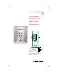
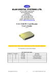
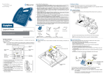
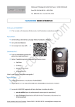
Operator Manual
NC001689
March 2001
Issue 3
CHATILLON® DFM Series
CADET® CD1 Series
- NOTICE This operator’s manual may be used for either the CHATILLON® DFM Series or AMETEK CADET® CD1 Series digital force gauges. The setup,
operation, calibration and maintenance instructions for these different brands of products are identical.
MODEL NUMBERS & CAPACITIES
CHATILLON® DFM Series
Model
DFM2
Capacity x Resolution
2 lb x 0.002 lb
1 kg x 0.001 kg
10 N x 0.01 N
CADET® CD1 Series
Model
CD1-002
Capacity x Resolution
2 lb x 0.002 lb
1 kg x 0.001 kg
10 N x 0.01 N
DFM10
10 lb x 0.01 lb
5 kg x 0.005 kg
50 N x 0.05 N
CD1-010
10 lb x 0.01 lb
5 kg x 0.005 kg
50 N x 0.05 N
DFM50
50 lb x 0.05 lb
25 kg x 0.02 kg
250 N x 0.2 N
CD1-050
50 lb x 0.05 lb
25 kg x 0.02 kg
250 N x 0.2 N
DFM100
100 lb x 0.1 lb
50 kg x 0.05 kg
500 N x 0.5 N
CD1-100
100 lb x 0.1 lb
50 kg x 0.05 kg
500 N x 0.5 N
Note:
Force gauges that use 220V source power for charging will
have the suffix “-220V” after the base model number, e.g. DFM2-220V.
- NOTICE Force reading accuracy may be affected by a low battery condition. BEFORE using the force gauge for the
first time, fully charge the rechargeable NiCd battery. Plug the charger into the gauge’s charge jack and into an
AC outlet.
Always charge the battery whenever the BAT indicator is highlited. A minimum charge of 8 hours is
recommended.
INTRODUCTION
The CHATILLON® DFM Series (or CADET ® CD1 Series) has been designed to be easy to setup, operate and
maintain. The instrument is ideal for tensile or compression measurement. The instrument may be supplied for
either 110V or 220V operation. Four base models are available for both the CHATILLON and CADET brands, each
model is distringuished by a different capacity. Capacities may be displayed in either lbs, kg or N measurements.
The instrument is supplied with a carrying case, battery charger, hex key, extension rod, hook and flat head
attachments.
ELECTRICAL SAFETY
These instruments have been assessed against the essentail heath and safety requirements of the Low Voltage
and the EMC Directives listed below. Based on conformity with the listed directives, the DFM and CD1 are
compliant with the following:
Directive
EMC Directive (89/336/EEC)
Low Voltage Directive (73/23/EEC)
Test Standard
EN 50081-1
EN 50082-1
EN 61010-1
EMC Generic Emissions Standard
EMC Generic Immunity Standard
Safety Requirement for Electrical Equip
SPECIFICATIONS
Accuracy:
+0.5% of Full Scale
Selectable Units:
lbs, kg, N
Overload Capacity:
110% of rated Capacity
Overload Protection:
Deflection:
Variable, <0.014-inches
(max) at full load
Temperature Range:
+40°F to +110°F
(+5°C to +45°C)
175% of rated Capacity
Temperature Stability:
0.06% per °F
Tare Capacity:
10% of full scale in lb
mode
Power:
Display:
LCD, updated 8 times/
second
115V, 60 Hz, <100 mA
220V, 50-60 Hz, <100 mA
8-10 hours between
charges
Sampling Rate:
1000 Hz
Battery Life (*):
Weight:
1.3 lbs (0.6 kg)
Warranty:
1 year
HANDHELD SETUP
The DFM/CD1 features a reversible split housing. The DFM/CD1 is factory assembled with the shaft pointed
down for stand mounting applications. If the gauge is to be used for handheld testing, it may be desireable to reorient the shaft so that it points upward.
-WARNING Extreme care should be taken when removing the housing. Make sure that you do not pull, twist or pinch any
of the wires inside the housing.
To change the shaft orientation perform the following:
1.
2.
3.
Remove the two hex screws on the backside of
the bottom housing using the Hex Key provided
with your gauge.
Carefully, rotate the top housing 180-degrees
making sure not to bind, twist or pull any of the
wires.
Reassemble the housing, making sure that no
wires are pinched between the top and bottom
housings.
TEST STAND MOUNTING
Two #10-32 tapped holes and a hole for a 3/16-inch
dowel pin are provided on the back of the force gauge.
These are used for mounting the gauge to a test stand.
1/2"
#10-32 Thd.
Mtg. Hole
(2 places)
2 1/4"
7"
TEST STAND ADAPTER KITS
Adapter kits are required when mounting your gauge to
a CHATILLON or AMETEK test stand. Please see the
Parts List section for part numbers.
2 11/16"
1 1/2"
DISPLAY READOUTS
v
T
C
PEAK
BAT
0000
C
PEAK
v
T
PEAK
PEAK
v
v
v
C
Indicates COMPRESSION in NORMAL mode
measured in kg.
LB
KG
N
Indicates PEAK TENSION mode measured in N.
LB
KG
N
Indicates PEAK COMPRESSION mode measured in
N.
LB
KG
N
Indicates LOW BATTERY condition. Battery MUST
be fully charged whenever a Low Battery Condition
occurs.
BAT
BAT
v
0000
v
PEAK
v
v
0000
C
LB
KG
N
BAT
v
0000
T
v
v
T
C
Indicates TENSION in NORMAL Mode measured
in lbs.
BAT
0000
T
LB
KG
N
v
-WARNING Force reading accuracy may be affected by a low battery condition. BEFORE using the force gauge for the
first time, fully charge the rechargeable NiCd battery. Plug the charger into the gauge’s charge jack and into an
AC outlet.
Always charge the battery whenever the BAT indicator is highlited. A minimum charge of 8 hours is
recommended.
BASIC OPERATIONS
Turn Gauge On/Off
Position side switch ON/OFF
Select Units of Measure
Select UNITS until desired UNIT is highlited
< LB, KG, N >
Select Force Type (Display Mode)
Select PEAK until desired TYPE is highlited
< NORM, T-PK, C-PK>
Zero (Tare) the Displayed Force Value
Select ZERO to tare and reset the displayed
value.
Zero All Force Values
Select and Hold
and then select ZERO. This
resets and tares all three display modes
simultaneously.
Reset Current Peak Reading
Select
value.
*
*
This does NOT change the tare
-NOTICE Always apply load axially. Applying load on an angle or ecentric loading may cause an erroneous force
reading.
OVERLOAD CONDITIONS
Extreme care should be taken to ensure that you do not overload the loadcell. Overload protection up to 175% of
the gauge’s capacity is provided in compression mode only, however, any overload condition may damage your
gauge. If you do overload the gauge, the display will flash with “0000” or “_ _ _ _”. If your gauge displays “-EP”
“-EPP” or “-EL”, contact your AMETEK or CHATILLON representative for service.
MAINTENANCE & CALIBRATION
You should routinely check and verify gauge accuracy by suspending a known weight from a hook adapter. If
calibration is required, please contact AMETEK or your local AMETEK representative.
To maintain optimum performance, we recommend a factory calibration every 12 months.
- WARNING This force gauge is equipped with a rechargeable battery. The battery is recyclable. It may be unlawful to
dispose of this battery into the municipal waste stream. Please check with yor local solid waste officials for
details on how to properly dispose of the battery.
PARTS LIST
50 52
88 87
15
56
11
16
12
88 50
50
88 51
54
53
53
53 59
54
54
54
58
55
54 54
89
57
89 57
58
89
57
89 57
58
89
57
TEST STAND ADAPTER KITS
Adapter kits are required when mounting your gauge to
a CHATILLON or AMETEK test stand. Please see the
Parts List section for part numbers.
Kit No.
NC000985
NC000985
LTCK-2
LTCK-2
HTCK-6
Chatillon Stand AMETEK Stand
TCM201
ACCUFORCE 201
TCD200
ACCUFORCE 200
LTS
MLTS
LTC
MLTS
HTC
MHTC
Model DFM and CD1 Series Parts Listing
Ref.
Part
No.
No.
NOTE:
Items with “*” after the Ref. No. are not shown.
CD1
CD1
CD1
CD1
Description
DFM DFM DFM DFM
2
10
50
100
002
010
050
100
11
SPK-FMG-011A
Adapter, Flat
1
1
1
1
1
1
1
1
12
SPK-FMG-012A
Adapter, Hook
1
1
-
-
1
1
-
-
SPK-FMG-012B
Adapter, Hook
-
-
1
1
-
-
1
1
SPK-FMG-015
Hex Key
1
1
1
1
1
1
1
1
15
16
50
SPK-FMG-016A Battery Charger, 115V
1
1
1
1
1
1
1
1
SPK-FMG-016B Battery Charger, 220V
1
1
1
1
1
1
1
1
SPK-DFM-050A
Top Case Assembly
1
-
-
-
-
-
-
-
SPK-DFM-050B
Top Case Assembly
-
1
-
-
-
-
-
-
SPK-DFM-050C
Top Case Assembly
-
-
1
-
-
-
-
-
SPK-DFM-050D
Top Case Assembly
-
-
-
1
-
-
-
-
51
SPK-DFM-051
Keypad
1
1
1
1
1
1
1
1
52
SPK-DFM-052A
Lens Assembly
1
-
-
-
-
-
-
-
53
54
SPK-DFM-052B
Lens Assembly
-
1
-
-
-
-
-
-
SPK-DFM-052C
Lens Assembly
-
-
1
-
-
-
-
-
SPK-DFM-052D
Lens Assembly
-
-
-
1
-
-
-
-
SPK-DFM-053
Printed Circuit Board
1
1
1
1
1
1
1
1
SPK-DFM-054A
Loadcell Assembly
1
-
-
-
1
-
-
-
SPK-DFM-054B
Loadcell Assembly
-
1
-
-
-
1
-
-
SPK-DFM-054C
Loadcell Assembly
-
-
1
-
-
-
1
-
SPK-DFM-054D
Loadcell Assembly
-
-
-
1
-
-
-
1
55
SPK-DFM-055
Power Jack Assembly
1
1
1
1
1
1
1
1
56
SPK-DFM-056
Extension Rod
1
1
1
1
1
1
1
1
57
SPK-DFM-057
Bottom Case Assembly
1
1
1
1
-
-
-
-
58
SPK-DFM-058
Battery Pack Assembly
1
1
1
1
1
1
1
1
59
SPK-DFM-059
EPROM, Programmed
1
1
1
1
1
1
1
1
61*
SPK-DFM-061
Carrying Case
1
1
1
1
-
-
-
-
87
SPK-CD1-087A
Lens Assembly
-
-
-
-
1
-
-
-
SPK-CD1-087B
Lens Assembly
-
-
-
-
-
1
-
-
SPK-CD1-087C
Lens Assembly
-
-
-
-
-
-
1
-
SPK-CD1-087D
Lens Assembly
-
-
-
-
-
-
-
1
88
SPK-CD1-088A
Top Case Assembly
-
-
-
-
1
-
-
-
SPK-CD1-088B
Top Case Assembly
-
-
-
-
-
1
-
-
SPK-CD1-088C
Top Case Assembly
-
-
-
-
-
-
1
-
SPK-CD1-088D
Top Case Assembly
-
-
-
-
-
-
-
1
89
SPK-CD1-089
Bottom Case Assembly
-
-
-
-
1
1
1
1
90*
SPK-CD1-090
Carrying Case
-
-
-
-
1
1
1
1
PRODUCT WARRANTY
This instrument is warranted against defects in workmanship, material and design for one (1) year from the date of delivery to the extent that
AMETEK will, at its sole option, repair or replace the instrument or any part thereof which is defective provided, however, that the warranty shall
not apply to instruments subjected to tampering or abuse, or exposed to highly corrosive conditions.
THIS WARRANTY IS IN LIEU OF ALL OTHER WARRANTIES WHETHER EXPRESS OR IMPLIED AND AMETEK HEREBY DISCLAIMS ALL
OTHER WARRANTIES, INCLUDING, WITHOUT LIMITATION, ANY WARRANTY OF FITNESS FOR A PARTICULAR PURPOSE OR
MERCHANTABILITY. AMETEK SHALL NOT BE LIABLE FOR ANY INCIDENTAL OR CONSEQUENTIAL DAMAGES, INCLUDING, BUT NOT
LIMITED TO, ANY ANTICIPATED OR LOST PROFITS.
This warranty is voidable if the purchaser fails to follow any and all instructions, warnings or cautions in the instrument’s operation manual.
If a manufacturing defect is found, AMETEK will replace or repair the instrument or replace any defective part thereof without charge; however,
AMETEK’s obligation hereunder does not include the cost of transportation which must be borne by the customer. AMETEK assumes no
responsibility for damage in transit, and any claims for such damage should be presented to the carrier by the purchaser.
TEST AND CALIBRATION INSTRUMENTS
AMETEK Test and Calibration
Instruments
8600 Somerset Drive
Largo, Florida 33773
USA
Tel
(727) 536-7831
Tel
(800) 527-9999
Fax
(727) 539-6882
Internet Addresses:
www.ametek.com
www.chatillon.com
www.lloyd-instruments.co.uk
AMETEK LLOYD
INSTRUMENTS
Forum House
12 Barnes Wallis Road
Segensworth East
Fareham
Hampshire PO 15 5TT
Tel
+44 (0) 1489 486399
Fax
+44 (0) 1489 8851118
AMETEK Precision
Instruments Europe GmbH
Rudolf-Diesel-Strasse 16
D-40670, Meerbusch
Germany
Tel
+49 2159 9136 0
Fax
+49 2159 9136 39
Information within this document is subject to change
without notice.
AMETEK and CHATILLON are registered trademarks of AMETEK, Inc.
Pub No. NC002490
Issued 03/01
AMETEK Singapore Pvt. Ltd.
10 Ang Mo Kio Street 65
#05-12 TECHPOINT
Singapore
569059
Tel
+65 484 2388
Fax
+65 481 6588
Copyright 2001, by AMETEK, Inc.
ISO 9001
Manufacturer
Printed in U.S.A.