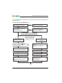
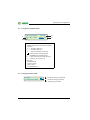
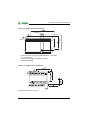
1
Operating Manual ISOMETER® isoLR275 Coupling device AGH-LR Insulation monitoring device for unearthed IT AC, AC/DC and DC systems for electrical installations with a low level of resistance up to AC 793 V / DC 1100 V Software version: D369 V2.1 TGH1468en/06.2012 Bender Inc. USA: 700 Fox Chase Coatesville, PA 19320 Toll Free: 800-356-4266 Phone: 610-383-9200 Fax: 610-383-7100 E-mail: [email protected] Canada: 5810 Ambler Drive, Unit 1 Mississauga, ON L4W 4J5 Toll Free: 800-243-2438 Phone: 905-602-9990 Fax: 905-602-9960 E-mail: [email protected] © Bender Inc. Web: http://www.bender.org All rights reserved. Content subject to change. Table of Contents 1. Safety instructions .................................................................................. 7 1.1 Intended use ............................................................................................................. 7 1.1.1 Personnel .................................................................................................................... 7 1.1.2 Hazards when handling the ISOMETER® isoLR275 ...................................... 7 1.1.3 Note .............................................................................................................................. 8 1.2 Explanation of symbols and notes .................................................................... 8 1.3 Directions for installation ..................................................................................... 9 2. Function ................................................................................................. 11 2.1 Device features isoLR275 .................................................................................... 11 2.2 Device features AGH-LR ...................................................................................... 12 2.3 Product description .............................................................................................. 12 2.4 Description of function ....................................................................................... 12 2.4.1 2.4.2 2.4.3 2.4.4 2.4.5 2.4.6 Measurement profiles .......................................................................................... 13 Self test ...................................................................................................................... 14 Current output for external measuring instrument .................................. 15 Real-time clock ....................................................................................................... 15 Coupled IT systems ............................................................................................... 15 Function input F1/F2 for connection or disconnection of IT systems being monitored ......................................................................... 16 2.4.7 ISOnet function (COM SETUP) ........................................................................... 18 3. Commissioning flow chart (in three parts) ...................................... 19 4. Installation and connection ............................................................... 23 4.1 Mounting of the isoLR275 .................................................................................. 23 4.2 Wiring diagram ....................................................................................................... 23 5. Operation and configuration ............................................................. 27 5.1 Display and operating elements ...................................................................... 27 TGH1468en/06.2012 3 Table of Contents 5.1.1 Display in standard mode ................................................................................... 28 5.1.2 Display in menu mode ......................................................................................... 28 5.1.3 Control buttons ...................................................................................................... 29 5.2 Menu structure and menu mode ................................................................. 31 5.2.1 5.2.2 5.2.3 5.2.4 Navigation within the menu .............................................................................. 31 Parameter change ................................................................................................. 31 Changing from the menu mode to the standard mode ......................... 31 Diagram menu structure ..................................................................................... 32 5.3 Menu HISTORY INFO .......................................................................................... 33 5.3.1 Diagram HISTORY INFO ....................................................................................... 34 5.4 Menu ISO SETUP: Setting of the basic ISOMETER® functions .................................................... 35 5.4.1 5.4.2 5.4.3 5.4.4 5.4.5 Response values Alarm1 and Alarm2 ............................................................. 35 Operating principle of the alarm relays ......................................................... 35 Memory setting (on/off) ...................................................................................... 37 Current output for external measuring instruments ................................ 37 Adjusting the current output to the centre scale mark of external measuring instruments ................................................................. 37 5.5 Menu ISO ADVANCED: Setting of the extended functions .................................................................. 39 5.5.1 5.5.2 5.5.3 5.5.4 External coupling device (AGH: PV) ................................................................ 39 Adaptation of the system leakage capacitance (Cemax: 150 μF) ........ 39 Changing the measurement method (Measure: AMP4) ......................... 39 Setting the repetition time for the automatic self test (Autotest: 24h) ........................................................................................................ 41 Setting the real-time clock (Clock) .................................................................. 41 Setting the date (Date) ........................................................................................ 41 Specifying the start-up time for the automatic self test (Test) .............. 41 Diagram ISO ADVANCED .................................................................................... 42 5.5.5 5.5.6 5.5.7 5.5.8 4 5.6 Menu COM SETUP: Setting the BMS interface ................................................................................... 43 5.6.1 5.6.2 5.6.3 5.6.4 Bus address "Addr:" ............................................................................................... 43 ISOnet function ...................................................................................................... 43 ISO monitor .............................................................................................................. 43 Diagram COM SETUP ............................................................................................ 44 TGH1468en/06.2012 Table of Contents 5.7 PASSWORD menu ............................................................................................... 45 5.7.1 Setting and activating the password ............................................................. 45 5.7.2 PASSWORD diagram ............................................................................................. 45 5.8 LANGUAGE Menu ............................................................................................... 46 5.8.1 Language setting ................................................................................................... 46 5.8.2 Language diagram ................................................................................................ 46 5.9 SERVICE menu ......................................................................................................... 46 6. Serial interface ....................................................................................... 47 6.1 RS-485 interface with BMS protocol ............................................................... 47 6.2 Topology RS-485 network .................................................................................. 48 6.2.1 Correct arrangement ............................................................................................ 48 6.2.2 Wrong arrangement ............................................................................................. 48 6.2.3 Wiring ......................................................................................................................... 48 6.3 BMS protocol ........................................................................................................... 49 6.3.1 BMS master .............................................................................................................. 49 6.3.2 BMS slave .................................................................................................................. 50 6.3.3 Commissioning of an RS-485 network with BMS protocol ..................... 51 7. Technical data isoLR275 with AGH-LR .............................................. 53 7.1 isoLR275 data in tabular form ........................................................................... 53 7.2 AGH-LR data in tabular form ............................................................................. 57 7.3 Standards, approvals and certifications ........................................................ 58 7.4 Characteristic curves ............................................................................................ 59 7.5 Ordering information ........................................................................................... 63 7.6 Label for modified versions ............................................................................... 63 INDEX ............................................................................................................ 65 5 TGH1468en/06.2012 1. Safety instructions 1.1 Intended use The ISOMETER® is intended for: monitoring the insulation resistance of IT systems Use which deviates from or is beyond the scope of these technical specifications is considered non-compliant. The Bender companies shall not be liable for any losses or damage arising therefrom. Intended use also implies: Compliance with all information in this operating manual and compliance with any test intervals. 1.1.1 Personnel Only appropriately qualified personnel may work on the ISOMETER®. Qualified means familiar with the installation, commissioning and operation of the product and with training appropriate to the work. Personnel must have read and understood the safety section and warning information in this operating manual. 1.1.2 Hazards when handling the ISOMETER® isoLR275 The ISOMETER® is constructed according to the state-of-the-art and the recognised technical safety rules. Nevertheless, when it is being used, hazards may occur to the life and limb of the user or third parties or there may be adverse effects on the ISOMETER® or on other valuable property. Only use the ISOMETER®: As intended In perfect working order Any faults which may impair safety must be eliminated immediately. Impermissible modifications and the use of spare parts and additional devices which are not sold and recommended by the manufacturer of the devices may cause fires, electric shocks and injuries. Unauthorised persons must not have access to or contact with the ISOMETER®. Information plates must always be clearly legible. Damaged or illegible signs must be replaced immediately. TGH1468en/06.2012 7 Safety instructions 1.1.3 Note Make sure that the operating voltage is correct! Prior to insulation and voltage tests, the ISOMETER® must be disconnected from the power system for the duration of the test. In order to check the proper connection of the device, it is recommended to carry out a functional test. Make sure that the basic settings meet the requirements of the IT system. Children and unauthorised persons must not have access to or contact with the ISOMETER®. 1.2 Explanation of symbols and notes To make it easier for you to understand and revisit certain sections of text and instructions in this manual, we have used symbols to identify important instructions and information. The meaning of these symbols is explained below: Information which refers to hazards is highlighted with the warning symbol Information which is designed to help you make the best use of the product is highlighted with the information symbol 8 TGH1468en/06.2012 Safety instructions 1.3 Directions for installation Only one insulation monitoring device may be used in each interconnected IT system. When insulation or voltage tests are to be carried out, the device shall be isolated from the system for the test period. The terminals and KE have to be connected by a separate wire to the protective conductor (PE). If the terminals L1, L2 of the device are connected to an IT system under operation, the terminals and KE must not be disconnected from the protective conductor (PE). In order to check the proper connection of the device, it is recommended to carry out a functional test using an insulation fault, e.g. via a suitable resistance, before starting the ISOMETER. The device variant -3.. is delivered with the following factory setting: ISO SETUP: ISO SETUP: ISO SETUP: ISO ADVANCED: COM SETUP: Alarm 1 / Alarm 2 (response values) Operating mode K1/K2 Memory System leakage capacitance Measurement method Bus address = 4 kΩ / 1 kΩ = = = = = N/O operation (N.O.) off 150 μF AMP 3 (slave) Please check if the factory setting of the ISOMETER® complies with the requirements of the IT system to be monitored. Response value Ran For correct setting of the response value in kΩ, it is useful to know the present value of the insulation resistance of the electrical installation. When the AC system being monitored contains galvanically coupled DC circuits: An insulation fault can only be monitored correctly when the rectifiers carry a continuous load current of 5...10 mA. TGH1468en/06.2012 9 Safety instructions 10 TGH1468en/06.2012 2. Function 2.1 Device features isoLR275 ISOMETER® for IT AC systems with galvanically connected rectifiers or converters and for IT DC systems (IT = unearthed systems) isoLR275 is always operated in conjunction with AGH-LR Automatic adaptation to the existing system leakage capacitance AMPPlus -Measurement method (European Patent: EP 0 654 673 B1) Choice of measurement methods to meet different requirements Two-line LC display Automatic device self test Particularly suited for monitoring electrical installations with a low level of resistance Two separately adjustable response ranges of 0.2 kΩ...100 kΩ each (Alarm 1, Alarm 2) Memory with real-time clock to store alarm messages with date and time stamp BMS interface (Bender Measuring Device Interface) for communication with other Bender devices (RS-485 galvanically isolated) Internal disconnection of the ISOMETER® from the IT system to be monitored (via control signal; terminals F1/F2), e.g. if several ISOMETER®s are interconnected Current output 0(4)...20 mA (electrically isolated) in relation to the insulation value measured in the system TGH1468en/06.2012 11 Function 2.2 Device features AGH-LR Coupling device required for ISOMETER® isoLR275, each AGH-LR is specially adapted to the corresponding isoLR275 Nominal voltage range AC 0...793 V and DC 0...1100 V DIN rail mounting 2.3 Product description The isoLR275 ISOMETER® in conjunction with the AGH-LR coupling device monitors the insulation resistance of IT systems. It is suitable for universal use in 3(N) AC, AC/ DC and DC systems. AC systems may include extensive DC-supplied loads, such as converters or thyristor-controlled DC drives. The adaptation to the existing system leakage capacitances takes place automatically. Only use the AGH-LR coupling device supplied with the device for adaptation of the nominal voltage range. The devices isoLR275 and AGH-LR are ideally adapted to each other. The corresponding combination device required in each case can be identified via the serial number on the device label. For repair work, both devices should be sent in in order to guarantee measuring accuracy. Otherwise, the measuring accuracy might be reduced! isoLR275 can share the BMS bus with other bus devices. 2.4 Description of function The isoLR275 ISOMETER® is connected between the unearthed system (IT system) and the protective conductor (PE) using the AGH-LR coupling device. The response values and other function parameters are set via the function buttons. The parameters are indicated on the LC display and are stored in a non-volatile memory (EEPROM). A microprocessor-controlled pulsating AC measuring voltage is superimposed on Plus -measurement method*). the IT system to be monitored ( AMP AMPPlus The measuring pulse consists of positive and negative cycles of the same amplitude. The period depends on the respective system leakage capacitances and the insulation resistance of the system to be monitored. 12 TGH1468en/06.2012 Function An insulation fault between system and earth closes the measuring circuit. The evaluation circuit calculates the insulation resistance which is indicated on the LC display or the external kΩ measuring instrument after the measuring time has expired. The measuring time is dependent on the selected measurement method, the system leakage capacitance, the insulation resistance and the system-related disturbances. System leakage capacitances do not influence the measuring accuracy. If the reading is below the selected response values Alarm 1/Alarm 2, the associated alarm relays respond, the LEDs "Alarm 1/2“ light up and the measuring value is indicated on the LC display (in the event of DC insulation faults, the faulty supply line is indicated). If the terminals R1/R2 are bridged (external reset button [N/C contact] or wire jumper), the fault message will be stored. Pressing the reset button, resets the fault message, provided that the insulation resistance is at least 25 % and at least 1 kΩ above the actual response value. The fault memory behaviour can also be set in the "ISO SETUP“ menu, by selecting the submenu Memory: on/off. Plus measurement method *) AMP AMPPlus (Adaptive Measuring Pulse), a measurement method developed by Bender (European Patent: EP 0 654 673 B1). 2.4.1 Measurement profiles The measuring circuit of the isoLR275 can be adjusted to different requirements in the ISO ADVANCED/MEASURE menu: DC = Suitable for pure AC systems AMP = Suitable for converters with frequencies > 10Hz AMP2 = Suitable for converters with frequencies < 10Hz AMP3 = Suitable for converters with frequencies < 1Hz AMP4 = Suitable for installations with strongly varying DC components Also refer to the table of measurement profiles starting from page 39. TGH1468en/06.2012 13 Function 2.4.2 Self test A self test can be started automatically or manually by means of the test button. In order to guarantee high functional reliability, the ISOMETER® provides comprehensive self test functions. After switching the device to the supply voltage, all internal measuring functions, the components of the process control such as data and parameter memory as well as system and earth connections are checked using the self test functions. The progress of the self test is shown on the display by a bar graph. Depending on the IT system conditions, the self test is completed after 15...20 seconds, then the message "Test ok!“ appears on the display for approximately two seconds. Then the device returns to the normal measuring mode and the currently measured value will be displayed once the measuring time has elapsed. When a device or connection fault is found, the message "!Error!“ appears on the display, the device error LED lights, the relay K2 (21-22-24) switches and the corresponding fault message (see table) will be indicated. If such a device error occurs, another self test is started after approximately one minute. If no more faults are detected, the fault message will automatically be deleted, the system fault LED will go out. During operation, the self test function can be started by pressing the test button (internal or external). The self test can also be started automatically every hour or every 24 hours by selecting the "ISO ADVANCED: Autotest:“ menu The alarm relays 1/2 only switch after starting the self test function by pressing the test button, that means, in case of an automatic self test the relays do not switch. Alarm message Connection PE? Description Actions No low-resistance con- 1. Check the wiring of the terminals and KE to earth (PE) nection between the terminals and KE 2. Press the test button to earth (PE). 3. Switch the supply voltage on and off 1. Press the test button Device error x Internal device error 2. Switch the supply voltage off and on 3. Please contact Bender 14 TGH1468en/06.2012 Function If, for functional reasons, the supply voltage cannot be switched on or off, a reset of the sequence control system can be carried out by pressing the buttons "ESC", "RESET" and "MENU“ simultaneously. 2.4.3 Current output for external measuring instrument The current output of isoLR275 is electrically isolated from the device electronics and the RS-485 interface. An output current range of 0...20 mA or 4...20 mA can be selected by means of the ISO SETUP menu, refer to page 36. In addition, the centre scale mark can be set to 28kΩ or 120kΩ, related to an external measuring instrument. 2.4.4 Real-time clock The real-time clock serves as a time base for the memory and self test functions. First, the correct time and date must be set in the "ISO ADVANCED“ menu. If time and date are not set, a "C“ (clock) is flashing in the standard display. In the event of a supply voltage failure, time and date will be stored for at least 30 days. When the 24 h self test is activated in the ISO ADVANCED menu, it is possible to set the time (hour) for carrying out the self test by means of the "TEST: 12:00" menu. Then a self test will be started automatically once a day exactly at the preset time. If the 1 h test has been selected, the self test is automatically carried out every full hour. 2.4.5 Coupled IT systems When using ISOMETER®s in IT systems, make sure that only one active ISOMETER® is connected in each interconnected system. If IT systems are interconnected via coupling switches, make sure that ISOMETER®s not currently used are disconnected from the IT system and deactivated. IT systems coupled via diodes or capacitances may also influence the insulation monitoring process so that a central control of the different ISOMETER®s is required. TGH1468en/06.2012 15 Function 2.4.6 Function input F1/F2 for connection or disconnection of IT systems being monitored The ISOMETER® can be disconnected from the IT system and set to STANDBY mode with the function input F1/F2. If the input F1/F2 is bridged, the connections to the coupling device AK1/AK2 are switched off via internal coupling relays, the measuring function is stopped and the message "STANDBY" appears on the display. Instead of the most recently measured value the value > 1 MΩ will be indicated. Furthermore, the alarm relays and alarm LEDs stop signalling alarm messages. After opening the function input F1/F2, the connection to the IT system will be restored and a completely new insulation resistance measurement cycle is started. This function can be used to disconnect an isoLR275 selectively in IT systems via the auxiliary contacts of the respective coupling switch. One coupling switch each in a line-type or ring-type arrangement can deactivate a subsequent isoLR275 to ensure that only one ISOMETER® is active in each galvanically connected IT system. If in a ring-type arrangement all coupling switches are closed, theoretically all ISOMETER®s would be deactivated. In order to prevent this, a BMS master (BMS addr. 1) monitors the condition of the function input F1/F2 of all slave ISOMETER®s. When all slave ISOMETER®s are in the STANDBY mode, the insulation monitoring function of the master ISOMETER® and hence the function input F1/F2 of the master are without function in this mode. Details are illustrated in the graphic below: 16 TGH1468en/06.2012 Function isoLR275 AGH-LR isoLR275 AGH-LR TGH1468en/06.2012 isoLR275 AGH-LR isoLR275 AGH-LR 17 Function 2.4.7 ISOnet function (COM SETUP) To activate this function, select "ISOnet=ON“ in the COM SETUP menu. This function is a type of scanning function. The BMS master with activated ISOnet function controls the ISOnet slave devices via the BMS bus. When the master ISOMETER® has finished one measuring cycle, the authorisation for insulation monitoring is passed on to the next higher BMS address. During the insulation monitoring process, all other ISOMETER®s are in the STANDBY mode. In this way it is prevented that ISOMETER®s influence each other in interconnected IT systems. In comparison to a solution with coupling switches and function input F1/F2, the response time will be extended because the measurement is not permanently carried out. This has the advantage that no auxiliary contacts of a coupling switch are required. Furthermore, this solution is recommended for IT systems coupled via capacitances or diodes. Each ISOnet slave checks the network for an ISOnet master. If no master exists, the fault "ISOnet Master?" will be output on the display. With the ISOnet function activated, the function input F1/F2 is automatically deactivated. isoLR275 AGH-LR isoLR275 AGH-LR 18 isoLR275 AGH-LR isoLR275 AGH-LR TGH1468en/06.2012 3. Commissioning flow chart (in three parts) Due to limitations of space, the three-part flow chart begins on the next page. TGH1468en/06.2012 19 Commissioning flow chart (in three parts) The encircled figures in the flow chart correspond to the figures in the legend to the wiring diagram. Commissioning of the ISOMETER® (1) Is the system to be monitored an unearthed system (IT system)? no isoLR is not suitable for this application( contact Bender) Is the maximum nominal voltage Un ≤ AC 793 V and is Un ≤ DC 1100 V no isoLR is not suitable for this application( contact Bender) Deenergize the installation before connecting the device! yes Device connection yes Recommended wire cross section of connecting cable single wire 0.2...4 mm2 flexible 0.2... 2.5 mm2 The two PE connections and KE must be connected separately to the equipotential bonding. 6 The terminals AK1 and AK2 must be connected by means of an AGH-LR to Un of the system to be monitored 2 3 4 5 Optional device connection An external kΩ measuring instrument at M+/MScale centre point: 28 kΩ or 120 kΩ Output current: 0/4...20 mA 10 External TEST button (NO contact) to the terminals T1 and T2 7 Connect the supply voltage Us to the terminals A1/+ and A2/-. Consider 1 the details indicated on the nameplate. External RESET button (NC contact) to the terminals R1 and R2 8 When using the RS485 interface, take care that a 120 Ω resistor is connected at the beginning and the end of the network. The output contacts of the alarm relays 12 System fault (21-22-24) 13 Alarm 1 (11-12-14) Alarm 2 (21-22-24) 20 11 TGH1468en/06.2012 Commissioning flow chart (in three parts) Commissioning of the ISOMETER® (2) Connect the supply voltage US The ISOMETER carries out a self test. The display indicates the insulation value after finishing the measurement Connect the voltage Un of the IT system to be monitored Set the clock Shall the basic setting be changed? Alarm1 = 4 kΩ Alarm2 = 1 kΩ K1/K2 = N/O operation Memory = off yes Select ISO SETUP (see chapter operation and setting) no Does one of the alarm LEDs light up? yes The insulation value of the system being monitored is below the preset response value. Change the response value or improve the insulation condition of the system no TGH1468en/06.2012 21 Commissioning flow chart (in three parts) Commissioning of the ISOMETER® (3) In order to check the proper connection, a functional test using a suitable resistance is to be carried out. Size of the resistance: 50% of the preset response value Alarm 2. Do both alarm LEDs light up? Did the alarm relays switch ? no yes Check the connecting leads ! Is voltage Un applied to the terminals L1/L2 ? of the coupling device AGH-LR? Check the voltages with a suitable voltmeter ! Do both alarm LEDs light ? Did the alarm relays switch? yes Remove the resistor ! no Alarm LEDs extinguished ? Did the output relays change their position ? yes isoLR is correctly connected and functions reliably ! 22 TGH1468en/06.2012 4. Installation and connection 4.1 Mounting of the isoLR275 Install the isoLR275 and the AGH-LR with a distance of at least 30mm to all adjacent devices to ensure compliance with prescribed temperature limits. The cable lengths between AGH-LR and isoLR275 must not exceed 0.5 m. For UL-Application: High Voltage Coupler AGH-PV should be mounted min. 30.8 mm away from the walls of a metal enclosure and uninsulated grounded parts and uninsulated live parts. 4.2 Wiring diagram The terminals A1/+ and A2/- are to be connected to the supply voltage Us according to IEC 60364-4-43, that means, the connections are to be protected against short-circuit by means of a protective device (a 6 A fuse is recommended). For UL and CSA applications, the use of 5 A fuses is mandatory. Devices for protection against short-circuit in conformity with IEC 60364-4-43 for the coupling of terminals L1/L2 of the AGH-LR the IT system being monitored can be omitted if the wiring is carried out in such a manner as to reduce the risk of a short-circuit to a minimum (a short-circuit-proof and earth-fault-proof wiring is recommended). An external test button or an external reset button may only be connected to one ISOMETER®. A parallel connection of several test and reset inputs for collective ISOMETER® testing is not allowed. For UL-Application: Use 60 °C/75 °C copper conductors only! Tightening torque: isoPV: 0.6 Nm...0.8 Nm, AGH-PV: 0.5 Nm TGH1468en/06.2012 23 Installation and connection 3 AC - System Un L1 L2 L3 3 AC - System L2 L1 L2 2 3/N AC - System Un L1 L2 L1 L2 L3 N DC - System 1 Us LL1 AGH-LR A2/- 6 AK1 AK2 isoLR275 24 9 10 K2 11 12 14 21 22 24 120 Ω mA 8 KE K1 T1 T2 R1 R2 F1 F2 M+ M- A B 7 PE AK2 AK1 A1/+ L2 L2 L1 -/~ 5 L+ Un L1 L2 +/~ 4 L1 Un 11 12 13 TGH1468en/06.2012 Installation and connection Legend wiring diagram: 1 Supply voltage US (see nameplate) via 6 A fuse; For UL and CSA applications, it is mandatory to use 5 A fuses. 2, 3 Connection to the 3 AC system to be monitored: Connect the terminals L1, L2 to neutral conductor N or terminals L1, L2 to conductor L1, L2. 4 Connection to the AC system to be monitored: connect terminals L1, L2 to conductor L1, L2. 5 Connection to the DC system to be monitored: Connect terminal L1 to conductor L+, terminal L2 to conductor L- 6 Separate connection of and KE to PE *7 External test button (N/O contact) *8 External reset button (N/C contact or wire jumper), when the terminals are open, the fault message will not be stored *9 STANDBY by means of the function input F1, F2: when the contact is closed, the insulation resistance is not measured. Disconnection from the IT system 10 Current output, electrically isolated: 0...20 mA or 4...20 mA 11 Serial interface RS-485 (termination with a 120 Ω resistor) 12 Alarm relay 1; available changeover contacts 13 Alarm relay 2 (device error relay); available changeover contacts * The wiring of the terminal pairs 7, 8 and 9 must be carried out galvanically isolated from each other and must not have a connection to PE! TGH1468en/06.2012 25 Installation and connection 26 TGH1468en/06.2012 5. Operation and configuration 5.1 Display and operating elements LR275 4 1 "INFO" button: to query standard information/ ESC button: back (menu function), to confirm parameter change 2 "TEST" button: to call up the self test/Arrow up button: parameter change, to move up in the menu 3 "RESET" button: to delete stored insulation fault alarms: Down button: parameter change, to move down in the menu 4 "MENU" button: to call up the menu system Enter button: Confirms parameter changes 5 Alarm LED 1 lights: insulation fault, first warning level reached 6 Alarm LED 2 lights: insulation fault, second warning level reached. 7 Device error LED lights: isoLR275 faulty 8 Two-line display for standard and menu mode A detailed description of the operating elements is given on the following pages. TGH1468en/06.2012 27 Operation and configuration 5.1.1 Display in standard mode 1 2 Insulation Rs=011kΩ Fa u l t 4 . H 3 1 Indication of the insulation resistance in kΩ 2 Additional information about the insulation resistance: „+“ = Insulation fault at L+ „–“ = Insulation fault at L– „s" = New measurement is running = Polarity of the measuring pulse, 3 . = Valid BMS bus communication, H = New entry in the memory data base C = Flashing, clock is to be set 4 Messages: - Insulation fault - Connection PE? - Device error x - *****STAND BY***** 5.1.2 Display in menu mode 1. EXIT 2. HISTORY INFO 28 Parameter change is permitted Parameter change is blocked, enabling by a password TGH1468en/06.2012 Operation and configuration 5.1.3 Control buttons Two functions are assigned to each function button. In addition to the basic function marked with a circle, the buttons allow navigation within the menu. Pressing the "INFO" button provides the following information ESC without opening the menu: INFO Device name, firmware version Response values Alarm1 and Alarm2 Leakage capacitance Ce (indication in case of insulation values > 20 kΩ), measurement not possible when using AMP3 and AMP4 Setup status (for details about the setup status refer to the status table on page 61) COM-Setup (own bus address) Please have the details above on hand if you have a problem and if you contact Bender for technical questions. Press the "TEST" button to start the self test of the ISOMETER®. TEST RESET Press the "RESET" button to reset insulation fault alarms stored in the ISOMETER®. The memory function is only available after activating the fault memory in the ISO SETUP menu or after bridging the terminals R1/R2. Furthermore, the fault memory of the ISOMETER® can only be reset when the measured insulation value is at least 25% or the value is 1 kΩ higher than the set response value. Press the "MENU" button to call up the menu system. MENU TGH1468en/06.2012 29 Operation and configuration For menu control, use the arrow buttons, the Enter button and the ESC button: TEST RESET MENU ESC INFO Up button: To move up in the menu, to increase the parameter value Down button: To move down in the menu, to decrease the parameter value Enter button To select a menu item or sub menu item, confirm or store a parameter change and to return to the associated sub menu item or skip to the next entry field. ESC button: To return from a sub menu to the previous menu. If the menu is not exited, the device automatically returns to the standard mode again after approximately five minutes. For the sake of clarity, the following symbols are used in the menu diagrams for the representation of ENTER, UP/DOWN and ESCAPE: ESC 30 TGH1468en/06.2012 Operation and configuration 5.2 Menu structure and menu mode To switch to the menu mode Press the "MENU" button to switch from the standard mode to the menu mode and to the main menu. From here you can branch to the different submenus. 5.2.1 Navigation within the menu Use the Up and Down buttons to select the appropriate menu item. A flashing cursor indicates which submenu is selected. Press the Enter button to call up the submenu of the associated menu. In the submenus, the appropriate parameters are also selected by means of the Up and Down buttons. Press the Enter button to move the cursor to the edit field. The "Arrow up" symbol tells you that you have reached the end of the menu list. 5.2.2 Parameter change When the password protection is activated (symbolised by "padlock closed" on the display), enter a valid password to be able to change parameters with the Up/ Down buttons. Once the password is entered correctly, all parameters can be changed as long as you stay in the menu. Changing the parameters usually has an immediate effect on the measuring and alarm functions. The changed parameter is stored in a non-volatile memory by pressing the Enter or ESC button after returning to the sub menu (flashing cursor in column 1). All measuring and alarm functions continue to run in the background during these menu operations. 5.2.3 Changing from the menu mode to the standard mode Pressing the ESC button allows fast changing from the menu mode to the standard mode. Thus, the menu item "EXIT" need not to be activated. If no button is pressed in a main or submenu, the system will automatically return from the menu mode to the standard mode after approximately five minutes. TGH1468en/06.2012 31 Operation and configuration 5.2.4 Diagram menu structure *** IT-SYSTEM *** R >1.0 MΩ H ESC MENU 1. EXIT 2. HISTORY INFO 3. ISO SETUP 4. ISO ADVANCED 5. COM SETUP 6. PASSWORD 7. LANGUAGE 8. SERVICE ESC HISTORY INFO ISO SETUP Nr.: 01 #Nr.: 02 Power on ISO ADVANCED 1. Exit 2. AGH : LR 3. Ce max: 150μF 4. Measure: AMP 5. Autotest: 24h 6. Clock: 19:08 7. Date: 01.01.01 8. Test: 00:00 1. Exit 2. Alarm1: 4.0 kΩ 3. Alarm2: 1.0 kΩ 4. K1 : N.O 5. K2 : N.O 6. Memory: on 7. M+/M-: 0-20 mA 8. M+/M-: Ri: 28kΩ 32 COM SETUP PASSWORD LANGUAGE 1. Exit 2. Password: XXX 3. Status: off 1. Exit 2. Addr: 003 3. ISONet: off 4. ISO Monitor SERVICE Insert Service Password: XXX 1. Exit 2. Text: Deutsch TGH1468en/06.2012 Operation and configuration 5.3 Menu HISTORY INFO 99 events with date and time stamp can be stored in the memory database. The database is designed as a ring memory, i.e. the eldest entry is overwritten. Data is written into a non-volatile memory and therefore is protected against voltage failure. Data record Event 1 2 3...99 3...99 3...99 3...99 3...99 3...99 3...99 3...99 3...99 3...99 3...99 Switch the supply voltage on Lowest measured insulation value Response value Alarm 1 released Response value Alarm 1 cleared Response value Alarm 2 released Response value Alarm 2 cleared Error system connection released Error system connection cleared Error PE connection released Error PE connection cleared Device error released Device error cleared System reset (watchdog) Display indication Power On Rmin Alarm1 Alarm1 Alarm2 Alarm2 System connection? System connection? PE connection? PE connection? Device error Device error System reset To store the events with the actual date and time stamp, you need to set the real-time clock in the ISO ADVANCED menu first. (refer to “Diagram ISO ADVANCED” auf Seite 42). Data can be queried via the "HISTORY INFO" menu as follows: to change the data record number use the Up/Down buttons, to toggle between the data record number and the menu item for clearing the history memory ("Clear all:on") use the Enter button, and to leave the menu item use the ESC button. In the standard mode, a new entry in the history memory is identified by an "H". To delete the "H" you have to open the HISTORY INFO menu item first. TGH1468en/06.2012 33 Operation and configuration 5.3.1 Diagram HISTORY INFO *** IT-SYSTEM *** R >1.0 MW H 1. EXIT 2. HISTORY INFO 3. ISO SETUP 4. ISO ADVANCED 5. COM SETUP 6. PASSWORD 7. LANGUAGE 8. SERVICE ESC Nr.: 01 #Nr: 08 Power on 34 Nr.: 01 #Nr: 08 Clear all: off Nr.: 01 #Nr: 08 28.08.01 17:43 Nr.: 02 #Nr: 08 Clear all: off Nr.: 02 #Nr: 08 Rmin: 010k Nr.: 02 #Nr: 08 Clear all: off Nr.: 02 #Nr: 08 25.08.01 10:13 Nr.: 02 #Nr: 08 Clear all: off TGH1468en/06.2012 Operation and configuration 5.4 Menu ISO SETUP: Setting of the basic ISOMETER® functions This menu is used to set the alarm functions Alarm1 and Alarm2 (prewarning and alarm), the operating principle of the alarm relays K1 and K2 (N.O = N/O operation, N.C = N/C operation), the fault storage behaviour and a selection of two current output ranges. For UL-application: In order to ensure the proper functioning of the relay outputs, a manual, periodic self-test where the relay outputs are switched, has to be carried out by the user (delivery condition). 5.4.1 Response values Alarm1 and Alarm2 The response values Alarm1 and Alarm2 are selected with the Up/Down button and stored with the Enter button. 5.4.2 Operating principle of the alarm relays K1/K2 are factory-set to N.O Test, that means N/O operation. When the supplement "Test" has been selected, the alarm relays switch over during a manual self test. If the operating principle of the alarm relays does not have to be changed during a manual self test for any reason, N.C or N.O. has to be selected. K1: N.C Test = N/C operation contacts 11-12-14, with relay test (the alarm relay is energised during normal operation) K1: N.O Test = N/O operation contacts 11-12-14, with relay test (the alarm relay is deenergised during normal operation) K1: N.C = N/C operation contacts 11-12-14, without relay test (the alarm relay is energised during normal operation) K1: N.O = N/O operation contacts 11-12-14, without relay test (the alarm relay is deenergised during normal operation) K1: Flash = Flashing function contacts 11-12-14 (The alarm relay switches and the LED flashes in the event of an alarm message at approx. 0.5 Hz) K2: N.C Test = N/C operation contacts 21-22-24, with relay test (the alarm relay is energised during normal operation) K2: N.O Test = N/O operation contacts 21-22-24, with relay test (the alarm relay is deenergised during normal operation) K2: N.C = N/C operation contacts 21-22-24, without relay test (the alarm relay is energised during normal operation) K2: N.O = N/O operation contacts 21-22-24, without relay test (the alarm relay is deenergised during normal operation) K2: Flash = Flashing function contacts 21-22-24 TGH1468en/06.2012 35 Operation and configuration (the alarm relay switches and the LED flashes in the event of an alarm message at approx. 0.5 Hz) ISO SETUP diagram *** IT-SYSTEM *** R >1.0 MW H 1. EXIT 2. HISTORY INFO 3. ISO SETUP 4. ISO ADVANCED 5. COM SETUP 6. PASSWORD 7. LANGUAGE 8. SERVICE 1. Exit 2. Alarm1: 4 kW 3. Alarm2: 1 kW 4. K1 : N.O 5. K2 : N.O 6. Memory: off 7. M+/M-: 0-20 mA Alarm1 : 4 kW Alarm2 : 1 kW 8. M+/M-: Ri: 28 kW K1: N.O K1: N.O Test K1: N.C Test K1: Flash K1: N.O K1: N.C K2: N.O Memory: off Memory: on Memory: off M+/M-: 0-20 mA M+/M-: 0-20 mA M+/M-: 4-20 mA M+/M-: Ri: 28 kW M+/M-: Ri: 28 kW M+/M-: Ri: 120 kW 36 TGH1468en/06.2012 Operation and configuration During the automatic self test, the alarm relays are not switched over. In case of a malfunction of the ISOMETER®, the relay K2 will automatically be activated as a device error relay. 5.4.3 Memory setting (on/off) Memory: on = Fault memory is activated The device must be reset with the reset button after clearing the fault Memory: off = Fault memory deactivated (factory setting) 5.4.4 Current output for external measuring instruments Factory setting: 0...20 mA The current output of the isoLR275 can be set to "0...20 mA" or "4...20 mA" via the "M+/M-:" menu item. The maximum load is 500 Ω. 5.4.5 Adjusting the current output to the centre scale mark of external measuring instruments Factory setting = 28kΩ Use the menu item "8. M+/M- Ri:“ in the ISO SETUP menu to select a centre scale mark. 8. M+/M- Ri:28k = centre scale RSk = 28kΩ (factory setting) 8. M+/M- Ri:120k = centre scale RSk =120kΩ (compatible to IRDH275..-4..) The function of the current output is dependent on the selected RSk. Function 0...20 mA: 20 mA x RSk RF = RF = insulation fault, I = current in mA I Function 4...20 mA: RF = insulation fault, I = current in mA RF = 16 mA x RSk I - 4 mA - RSk - RSk Refer to the associated characteristic curves on page 59. TGH1468en/06.2012 37 Operation and configuration For UL-applications: The analogue output as such is not a “safe alarm” indication in compliance with UL1998. If the analogue output is intended to be used as a “safe alarm”: – the relay output (at least K1 or K2) must additionally be used to provide redundancy OR – both the relay outputs and the analogue output must be evaluated during the cyclic self-test, in order to ensure the proper functioning of the analogue output. 38 TGH1468en/06.2012 Operation and configuration 5.5 Menu ISO ADVANCED: Setting of the extended functions 5.5.1 External coupling device (AGH: PV) Use the isoLR275 only in conjunction with the AGH-LR coupling device. The menu setting AGH:PV is pre-defined. The current software version does not allow other settings. 5.5.2 Adaptation of the system leakage capacitance (Cemax: 150 μF) This menu can be used to adapt the ISOMETER® to the maximum system leakage capacitance (max. 500μF). Refer to the table "Measurement profiles" for details about the duration of the response time. Factory setting = 150 μF 5.5.3 Changing the measurement method (Measure: AMP4) In IT systems, the voltage of which changes at low-frequency as a consequence of operation, the response time tan depends on the lowest frequencies occurring between system and earth during operation. This is typical of converter systems including low-frequency control processes and direct current motors with low-frequency control processes. In order to improve the quality of insulation measurements in the different applications and to avoid incorrect measurements, the special measurement method suited for the individual application can be selected. In the following table, the response times in relation to the selected maximum leakage capacitance are listed and also the measurement profile to be set for the respective application. Please note that the capacitance cannot be measured when using the profiles AMP3 or AMP4. Hence, no result will be displayed when the current leakage capacitance is queried by means of the INFO button. TGH1468en/06.2012 39 Operation and configuration Setting the parameter Ce max 40 Profile setting Description 150μF 500μF Response time tan Response time tan (acc. to IEC 61557-8) Ran = 1kΩ Ce = 1μF Ran = 1kΩ Ce = 200μF DC Standard measurement method using a DC measuring voltage for pure AC systems < 3s DC measurement method permissible for Ce < 10μF only AMP Standard measurement method using the pulse measurement method for AC/DC systems at system frequencies > 10Hz (factory setting) < 16s < 40s AMP2 Optimised measurement method using the pulse measurement method for AC/DC systems at system frequencies < 10Hz < 30s < 50s AMP3 Optimised measurement method for AC/DC systems at system frequencies < 1Hz < 140s < 140s AMP4 Optimised measurement method for installations comprising strongly varying DC components < 370s < 400s TGH1468en/06.2012 Operation and configuration 5.5.4 Setting the repetition time for the automatic self test (Autotest: 24h) The time for the repetition of automatic self tests can either be set to 1 hour or to 24 hours or can be deactivated. Factory setting = 24 h 5.5.5 Setting the real-time clock (Clock) The time setting is the time base for the memory and the automatic self test. In case of supply voltage failure, the set real-time clock keeps running for approximately 30 days. When the device is switched on after this period, a flashing "C" appears on the display and the clock has to be set again. 5.5.6 Setting the date (Date) Not only is the time of day required but also the date has to be set for the history memory. In the event of supply voltage failure, the date function is not influenced for at least 30 days. When switching the device on at a later date, a new setting of the real-time clock and the date is required. 5.5.7 Specifying the start-up time for the automatic self test (Test) When the 24 h self test is activated in the ISO ADVANCED menu, it is possible to set the time (hour) for carrying out the self test by means of the "TEST: 12:00" menu item. Then the self test is automatically carried out once a day at a given time. When the 1 hour auto test has been selected, the self test is carried out at every full hour. TGH1468en/06.2012 41 Operation and configuration 5.5.8 Diagram ISO ADVANCED *** IT-SYSTEM *** R >1.0 MΩ H 1. 2. 3. 4. 5. 6. 7. 8. EXIT HISTORY INFO ISO SETUP ISO ADVANCED COM SETUP PASSWORD LANGUAGE SERVICE 1. Exit 2. AGH: PV 3. Ce max : 150μF 4. Measure: AMP 5. Autotest: 24h 6. Clock: 21:09 7. Date: 01.01.01 8. Test: 12:00 Ce max : 150μF 150μF 500μF Measure: AMP Autotest: 24h DC AMP AMP2 AMP3 AMP4 24h no 01h Clock: 21:09 Date: 01.01.01 Test: 00:00 00:00 . . . 23:00 42 TGH1468en/06.2012 Operation and configuration 5.6 Menu COM SETUP: Setting the BMS interface 5.6.1 Bus address "Addr:" This menu is used to set the BMS bus address for isoLR275. Take care that the bus address is not assigned twice. The device is factory set to address 3 and hence operates as a slave. If several isoLR275s are operated on one BMS bus, the address of other ISOMETER®s must be assigned one after the other, since only one device may have the master function. 5.6.2 ISOnet function The ISOnet function can be set in the COM SETUP menu under ISOnet = ON. The ISOnet function of all ISOMETER®s existing in the system must be set to "ON". The BMS master with activated ISOnet function controls the ISOnet slave devices via the BMS bus. When the master ISOMETER® has finished one measuring cycle, the authorisation for insulation monitoring is passed on to the next slave device. During the insulation monitoring process, all other ISOMETER®s are in the STANDBY mode. 5.6.3 ISO monitor This function allows to query the currently measured value as well as the messages of all bus-capable ISOMETER®s existing in the BMS network. After selecting the bus address, the entire information stored by the selected device is indicated on the display. The display indication is structured similar to the standard indication, but instead of the indication of the measuring pulse, the selected bus address is indicated. Without pressing a button, the indication changes to the standard indication of the isoLR275 after about five minutes. If there is no information available from the selected ISOMETER®, the message "!!!!NO DATA!!!!“ will be displayed. Information is being searched: <<BUS SC ANNING>> R= ADR:02 No data found: ! ! ! ! N O D ATA ! ! ! ! R= ADR:02 Current data address 03: I n s u l at i o n Fa u l t R= 010K ADR:03 TGH1468en/06.2012 43 Operation and configuration 5.6.4 Diagram COM SETUP *** IT-SYSTEM *** R >1.0 MW H 1. EXIT 2. HISTORY INFO 3. ISO SETUP 4. ISO ADVANCED 5. COM SETUP 6. PASSWORD 7. LANGUAGE 8. SERVICE 1. Exit 2. Addr: 003 3. ISONet: off 4. ISO Monitor Addr : 003 ADR: 001 . . . ADR: 030 ISONet : off ISONet : off ISONet : on ! ! ! ! NO DATA ! ! ! ! R= ADR: 01 44 ADR: 01 . . . ADR: 30 TGH1468en/06.2012 Operation and configuration 5.7 PASSWORD menu 5.7.1 Setting and activating the password This menu can be used to activate a "Password" query. This protects the ISOMETER® against unauthorised settings and modifications. Set the desired password using the Up/Down buttons (menu item "2. Password: xxx") password: and confirm the setting with the Enter button. Activate the password in the "3. Status: on" menu by clicking the Enter button. The factory setting is "3. Status: off". 5.7.2 PASSWORD diagram *** IT-SYSTEM *** R >1.0 MW H 1. EXIT 2. HISTORY INFO 3. ISO SETUP 4. ISO ADVANCED 5. COM SETUP 6. PASSWORD 7. LANGUAGE 8. SERVICE 1. Exit 2. Password: XXX 3. Status: off Password: XXX Password: XXX Password: 000 Password: . . . Password: 999 Status: off Status: off Status: on TGH1468en/06.2012 45 Operation and configuration 5.8 LANGUAGE Menu 5.8.1 Language setting The menu item "Language" allows fault messages of the ISOMETER® to be set to different languages. There is a choice of German and English. The device menu is not influenced by the language selection. 5.8.2 Language diagram *** IT-SYSTEM *** R >1.0 MW H 1. EXIT 2. HISTORY INFO 3. ISO SETUP 4. ISO ADVANCED 5. COM SETUP 6. PASSWORD 7. LANGUAGE 8. SERVICE 1. Exit 2. Text: Deutsch 2. Text: Deutsch 2. Text: Deutsch 2. Text: English 5.9 SERVICE menu This menu item is intended for the Bender service personnel and protected by a password against erroneous settings. It is intended for fast fault clearance by qualified experts in the event of a device error. 46 TGH1468en/06.2012 6. Serial interface 6.1 RS-485 interface with BMS protocol The RS-485 interface electrically isolated from the device electronics and the current output serves as a physical transmission medium for the BMS protocol. If several isoLR275 or other bus-capable devices are interconnected in a network via the BMS bus, the BMS bus must be terminated at both ends with a 120 Ω resistor. An RS-485 network that is not terminated, is likely to get instable and may result in malfunctions. Only the first and the last device in one line may be terminated. Devices in between must not be terminated with 120 Ω. Hence, stub feeders in the network must not be terminated. The length of the stub feeders is restricted to 1 meter. 1st device A 120 W 0.4 W B ... device A last device B Stub feeder maximum 1 m A B 120 W 0.4 W Maximum length of the RS485 bus: 1200 m TGH1468en/06.2012 47 Serial interface 6.2 Topology RS-485 network The optimum topology for the RS-485 network is a daisy-chain connection. In this connection, device 1 is connected to device 2, device 2 to device 3, device 3 to device n etc. The RS-485 network represents a continuous path without branches. 6.2.1 Correct arrangement Three examples for correct arrangement: 6.2.2 Wrong arrangement Three examples for wrong arrangement: 6.2.3 Wiring The suitable type of wiring for the RS-485 network is: shielded cable, core diameter ≥ 0.6 mm (e.g. J-Y(St)Y 2x0.6), shield connected to earth (PE) on one end. Connection to the terminals A and B. The number of bus nodes is restricted to 32 devices. When more devices are to be connected, Bender recommends to use a DI1 repeater. 33 1 64 32 DI1 48 TGH1468en/06.2012 Serial interface 6.3 BMS protocol This protocol is an essential part of the Bender measuring device interface (BMS bus protocol). Data transmission generally makes use of ASCII characters. Interface data are: Baud rate: 9600 baud Transmission: 1 start bit, 7 data bits, 1 parity bit, 1 stop bit (1, 7, E, 1) Parity: even Checksum: Sum of all transmitted bytes = 0 (without CR and LF) The BMS bus protocol works according to the Master-Slave principle. That means that one device represents the master while all other bus devices are slaves. It is important that only one master is present in each network. All bus devices are identified by a unique address. The master scans all other devices on the bus cyclically, listens to their signals and then carries out specific commands. Bus address 1 must be assigned to the master, thus to one of the isoLR275 devices. 6.3.1 BMS master A master can query all warning and operational messages from a slave. If the bus address 1 has been selected for one isoLR275, the device automatically represents the master, that means that all addresses between 1 and 150 are cyclically scanned for alarm and operational messages via the BMS bus. If the master receives no answer from five subsequent addresses, the scanning cycle is started again. If the master recognises incorrect answers from a slave, the fault message "Fault RS-485" will appear on the display. Fa u l t R S 4 8 5 Rs=011kW TGH1468en/06.2012 . H 49 Serial interface Fault causes may be: Addresses are assigned twice A second master exists on the BMS bus Interference signals occur on the bus lines A defective device is connected to the bus Terminating resistors are not activated 6.3.2 BMS slave All isoLR275 devices are factory-set to slave mode (address 3). In a BMS network, one address must be selected from the address range 2...30 for each slave. There may be no gaps of more than five subsequent addresses, so that all slaves can be scanned by the master. For isoLR275 a BMS address can be selected from the address range 1...30. When assigning the addresses, also other devices such as EDS4xx must be considered. The receipt of the BMS data is indicated by a flashing point on the display on the right of the measuring pulse indication. ***IT-SYSTEM *** R+=500KW Flashing point: BMS data received If no flashing point appears, it may be attributed to the following: No master available in the network More than one master available in the network RS-485 interface (terminals A/B) not connected or reversed 50 TGH1468en/06.2012 Serial interface The following table gives an overview about essential alarm messages and the assignment of the messages indicated on the display or alarm indicator and test combinations, e.g. MK800. Alarm Channel Note Insulation Fault 1 Insulation resistance < setting value Alarm 1 Insulation Fault 2 Insulation resistance < setting value Alarm 2 Mains power connection 3 Connection fault L1/L2 against IT system Connection PE 4 Connection fault Device error 5 Internal device error /KE against PE conductor In the standby mode, the BMS function is completely available (Stand-by: F1/F2). 6.3.3 Commissioning of an RS-485 network with BMS protocol Connect the terminals A and B of all bus devices in one line Switch the supply voltage on. Determine one isoLR275 as the master and assign address 1 Switch the terminating resistors on at the start and the end of the RS-485 network. If a device at the end of the bus is not terminated, connect a 120 Ω resistor to the terminals A and B. Assign the addresses (2...30) subsequently to all other isoLR275 and other bus devices (see table below) Check whether a flashing point appears on all devices (BMS commands are being received) The sub menu "ISO-Monitor" in the COM SETUP menu allows insulation values of the ISOMETER®s to be queried. Enter the address of the ISOMETER® before starting the query. TGH1468en/06.2012 51 Serial interface BMS bus address ranges (internal bus) Addresses* Device 0 1...30 1...30 1...90 1...90 1...150 111...119 121...150 IRDH275B/ 375B/575; isoPV isoLR275 FTC4... COM460IP EDS46.../49... MK800 PGH47... PGH47...E Note There is no device with address 0 ! Information sent to address 0 applies to all devices connected to the interfaces (broadcast) Insulation monitoring devices Protocol converters Protocol converters Insulation fault locators (EDS) Alarm indicator and test combination Locating current injector Locating current injector * Assign the addresses consecutively, there must be no gaps greater than five in the respective ranges (1...30, 31...60, 61...90, 111...119 and 121...151) 52 TGH1468en/06.2012 7. Technical data isoLR275 with AGH-LR 7.1 isoLR275 data in tabular form The values marked with** are absolute values ()* = factory setting Insulation coordination acc. to IEC 60664-1 / IEC 60664-3 Rated voltage for isoLR275-3 ......................................................................................................AC 250 V Rated impulse voltage/pollution degree ..................................................................................... 6 kV / III Protective separation (reinforced insulation) between.............................................................................. .........(A1/+, A2/-) - (11,12, 14, 21, 22, 24) - (AK1, AK2, KE, PE, T1, T2, R1, R2, F1, F2, M+, M-, A, B) Voltage test acc. to IEC 61010-1 ................................................................................................. 3.536 kV Rated insulation voltage...............................................................................................................AC 250 V Rated impulse voltage/pollution degree ..................................................................................... 4 kV / III Basic insulation between: ................................................................................ (11, 12, 14) - (21, 22, 24) Voltage test acc. to IEC 61010-1 ................................................................................................... 2.21 kV Voltage ranges Nominal system voltage Un ..................................................................................................... via AGH-LR isoLR275-335: Supply voltage Us (also see nameplate) ......................................................................... AC 88...264 V** Frequency range Us ................................................................................................................. 42...460 Hz Power consumption .................................................................................................................. ≤ 21,5 VA Supply voltage Us (also see nameplate) ......................................................................... DC 77...286 V** Power consumption..................................................................................................................... ≤ 5,5 VA isoLR275-327: Supply voltage Us (also see nameplate)........................................................................ DC 19.2...72 V** Power consumption........................................................................................................................ ≤ 6 VA For UL-application: Nominal system voltage Un ..................................................................................................... via AGH-LR isoLR-335: Supply voltage Us (also see nameplate) .............................................................................. AC 88...250 V Frequency range Us ................................................................................................................. 42...460 Hz Power consumption AC ............................................................................................................ ≤ 21,5 VA Supply voltage Us (also see nameplate) .............................................................................. DC 80...250 V Power consumption DC .............................................................................................................. ≤ 5,5 VA TGH1468en/06.2012 53 Technical data isoLR275 with AGH-LR isoLR-327: Supply voltage Us (also see nameplate)................................................................................ DC 24...65 V Power consumption ...................................................................................................................... ≤ 6 VA Response values Response value Ran1 ............................................................................................................. 0.2...100 kΩ Factory setting Ran1 (Alarm1) ........................................................................................................... 4 kΩ Response value Ran2 .............................................................................................................. 0.2...100 kΩ Factory setting Ran2 (Alarm2) ........................................................................................................... 1 kΩ Relative uncertainty (7 kΩ...100 kΩ) (acc. to IEC 61557-8:2007-01) ........................................ ±15 % Relative uncertainty (0.2 kΩ...7 kΩ)............................................................................................. ±1 k Ω Response time tan ................................................................................... see table starting from page 39 Hysteresis ............................................................................................................................ 25 %, +1 k Ω Measuring circuit Measuring voltage Um (peak value)............................................................................................... ± 50 V Measuring current Im (at RF = 0 Ω).......................................................................................... ≤ 1.5 mA Internal DC resistance DC Ri......................................................................................................... ≥ 35 k Ω Impedance Zi at 50 Hz................................................................................................................. ≥ 35 k Ω Permissible extraneous DC voltage Ufg ................................................................................. ≤ DC 1100 V Max. system leakage capacitance Ce ......................................................................... ≤ 500 μF (150 μF)* Displays Display....................................................................................................................backlit two-line display Characters (number / height)............................................................................................. 2 x 16 / 4 mm Display range measured value ........................................................................................ 0.2 k Ω....1 MΩ Operating uncertainty ...................................................................................................... ±15%, ±1 k Ω Outputs/Inputs Test/reset button............................................................................................................. internal/external Cable length test/reset button, external ....................................................................................... ≤ 10 m Current output (load) ............................................................................................... 0/4...20 mA (500 Ω) Accuracy current output, related to the value indicated (1 k Ω...100 kΩ) ........................................................... ±15 %, ±1 k Ω Serial interface Interface/protocol ................................................................................................................RS-485 / BMS Connection terminals .......................................................................................................................... A/B Cable length .............................................................................................................................. ≤ 1200 m Shielded cable (shield to PE on one end)................................. 2-core, ≥ 0.6 mm2, e. g. J-Y(St)Y 2x0.6 Terminating resistor ........................................................................................................... 120 Ω (0.5 W) 54 TGH1468en/06.2012 Technical data isoLR275 with AGH-LR Device address, BMS bus .......................................................................................................... 1...30 ( 3)* Switching elements Switching elements............................ 2 changeover contacts: K1 (Alarm1), K2 (Alarm2, device error) Operating mode K1, K2 (Alarm1 / Alarm2) ............................................................................................... ................................................................. N/C operation n.c. / N/O operation n.o. (N/O operation n.o.)* Contact data acc. to IEC 60947-5-1: Utilisation category .............................................. .... AC 13..... AC 14 .... DC-12..... DC-12........ DC-12 Rated operational voltage ................................... .... 230 V..... 230 V ....... 24 V..... 110 V........ 220 V Rated operational current..................................... ......... 5 A......... 3 A ......... 1 A...... 0.2 A......... 0.1 A Minimum contact rating........................................................................................ 1 mA at AC/DC ≥ 10 V Environment/EMC EMC ............................................................................................................................................................. not suitable for household and small companies.............................................................. IEC 61326-2-4 Operating temperature .................................................................................................... -25 ºC...+65 ºC Classification of climatic conditions acc. to IEC 60721: Stationary use (IEC 60721-3-3) ......................................3K5 (with condensation and formation of ice) Transport (IEC 60721-3-2) ..............................................2K3 (with condensation and formation of ice) Long-term storage (IEC 60721-3-1) ...............................1K4 (with condensation and formation of ice) Classification of mechanical conditions acc. to IEC 60721: Stationary use (IEC 60721-3-3) ................................................................................................................. for screw fixing with accessories B990056 ........................................................................................ 3M7 for DIN rail mounting.......................................................................................................................... 3M4 Transport (IEC 60721-3-2) ................................................................................................................ 2M2 Long-term storage (IEC 60721-3-1) ................................................................................................. 1M3 Connection Connection............................................................................................................... screw-type terminals Connection, rigid/flexible............................................................................ 0.2...4 mm2 / 0.2...2.5 mm2 Connection flexible with ferrule, without/with plastic sleeve ......................................... 0.25...2.5 mm2 Tightening torque............................................................................................................................0.5 Nm Conductor sizes (AWG).................................................................................................................... 24...12 Cable length between isoLR275 and AGH-LR ............................................................................ ≤ 0.5 m Other Operating mode ...................................................................................................... continuous operation Mounting ........................................................................................................................ display-oriented Distance to adjacent devices ...................................................................................................... ≥ 30 mm Degree of protection, internal components (DIN EN 60529) ..............................................................IP30 Degree of protection, terminals (DIN EN 60529).................................................................................IP20 TGH1468en/06.2012 55 Technical data isoLR275 with AGH-LR Type of enclosure................................................................................................. X112, free from halogen DIN rail mounting............................................................................................. DIN EN 60715 / IEC 60715 Screw mounting by means of support (see page 62).................................................................... 2 x M4 Flammability class....................................................................................................................... UL94 V-0 Software version ....................................................................................................................... D369 V2.1 Weight ............................................................................................................................................< 510 g ()* = factory setting The values marked with** are absolute values 56 TGH1468en/06.2012 Technical data isoLR275 with AGH-LR 7.2 AGH-LR data in tabular form Insulation coordination acc. to IEC 60664-1 Rated insulation voltage.............................................................................................................. AC 800 V Rated impulse voltage/pollution degree.........................................................................................8 kV/3 Voltage ranges Nominal system voltage Un ............................................................. AC, 3(N)AC 0...793 V, DC 0...1100 V Nominal frequency fn ........................................................................................................ DC, 10...460 Hz Max. AC voltage U~ in the frequency range fn = 0.1...10 Hz: ......................... U~ max = 110 V/Hz * fn Environment/EMC EMC .................................................................................................................................... IEC 61326-2-4 Operating temperature .................................................................................................... -25 ºC...+65 ºC Classification of climatic conditions acc. to IEC 60721: Stationary use (IEC 60721-3-3) ......................................3K5 (with condensation and formation of ice) Transport (IEC 60721-3-2) ..............................................2K3 (with condensation and formation of ice) Long-term storage (IEC 60721-3-1) ...............................1K4 (with condensation and formation of ice) Classification of mechanical conditions acc. to IEC 60721: Stationary use (IEC 60721-3-3) ........................................................................................................ 3M7 Transport (IEC 60721-3-2) ................................................................................................................ 2M2 Long-term storage (IEC 60721-3-1) ................................................................................................. 1M3 Connection Connection............................................................................................................... screw-type terminals Connection, rigid/flexible............................................................................ 0.2...4 mm2 / 0.2...2.5 mm2 Connection flexible with ferrules, without/with plastic sleeve........................................ 0.25...2.5 mm2 Tightening torque............................................................................................................................0.5 Nm Conductor sizes (AWG).................................................................................................................... 24...12 Cable length between isoLR275 and AGH-LR ............................................................................ ≤ 0.5 m Other Operating mode .......................................................................................................continuous operation Mounting ............................................................................... cooling slots must be ventilated vertically! Distance to adjacent devices ...................................................................................................... ≥ 30 mm Degree of protection, internal components (DIN EN 60529) ..............................................................IP30 Degree of protection, terminals (DIN EN 60529).................................................................................IP20 Type of enclosure.................................................................................................X200, free from halogen DIN rail mounting ............................................................................................ DIN EN 60715 / IEC 60715 Screw mounting .............................................................................................................................. 2 x M4 Flammability class ...................................................................................................................... UL94 V-0 TGH1468en/06.2012 57 Technical data isoLR275 with AGH-LR Weight ............................................................................................................................................< 230 g 7.3 Standards, approvals and certifications The ISOMETER® was designed in compliance with the following standards: - DIN EN 61557-8 (VDE 0413-8) - IEC 61557-8 - IEC 61326-2-4 - DIN EN 60664-1 (VDE 0110-1) - DIN EN 60664-3 (VDE 0110-3) 58 TGH1468en/06.2012 Technical data isoLR275 with AGH-LR 7.4 Characteristic curves Current output 0...20 mA RF[k] 1000,00 Rsk=28kOhm Rsk=120kOhm 100,00 10,00 1,00 0,0 5,0 10,0 15,0 20,0 25,0 I[mA] RF = 20 mA x RSk I - RSk RF = Insulation fault in kΩ RSk = Centre scale in kΩ I = Current output in mA TGH1468en/06.2012 59 Technical data isoLR275 with AGH-LR Current output 4...20 mA RF[k] 1000,00 Rsk=28kOhm Rsk=120kOhm 100,00 10,00 1,00 0,0 5,0 RF = 10,0 16 mA x RSk I - 4 mA 15,0 20,0 25,0 I[mA] - RSk RF = Insulation fault in kΩ RSk = Centre scale in kΩ I = Current output in mA 60 TGH1468en/06.2012 TGH1468en/06.2012 Value: 5 ... 9 Number of pulses 2-9 ** 14 15 ** The parameters marked with two asterisks are settable via the Service menu item! A password is required for that purpose ! Value: 5 ... 9 Value: 5 ... 9 Bus address in the units place IRDH275 test data ** 13 Isodata ** min. filter frequency 50Hz ** AMP4 measuring principle K2: N/C operation K1: N/C operation 4= BMS mode ** min. filter frequency 10Hz ** max. filter frequency 50Hz ** AMP3 measuring principle Cemax 500 μF K2: N/O operation K1: N/O operation 3= Bus address in the tens place IRDH275 min. filter frequency 1Hz ** min. filter frequency 0,1Hz ** 11 max. filter frequency 10Hz ** AMP2 measuring principle no periodic self test Cemax 150 μF K2: flashing function K1: flashing function 2= 12 max. filter frequency 1Hz ** max. filter frequency 0.1Hz ** 9 10 DC measuring principle AMP measuring principle 8 Self test every hour Language English Self test every 24 hours 6 AK AGH-PV Cemax 10 μF ** Password protection activated Cemax 1 μF ** 3 4 5 K2: N/C operation Test Language German K2: N/O operation Test 2 K1: N/C operation Test Password protection not activated K1: N/O operation Test 1 1= Value of the respective number 7 0= Position of numbers from the left Technical data isoLR275 with AGH-LR Status number 61 Technical data isoLR275 with AGH-LR Dimension diagram enclosure isoLR275 81 mm ø 4,5 mm DIN rail mounting according to DIN EN 60715 / IEC 60715 Screw mounting by means of a plug-in trapezoidal support Order-No. B990056 Dimension diagram enclosure AGH-LR mm Illustration with terminal covers 62 TGH1468en/06.2012 Technical data isoLR275 with AGH-LR 7.5 Ordering information Nominal voltage Un Supply voltage Us isoLR275-327 + AGH-LR-3 3(N) AC 0...793 V DC 0...1100 V DC 19.2...72 V B 9106 5702W consisting of: isoLR275-327 AGH-LR ----- ----- B 9106 5700W B 9803 9022W isoLR275-335 + AGH-LR 3(N) AC 0...793 V DC 0...1100 V AC 88...264 V DC 77...286 V B 9106 5703W consisting of: isoLR275-335 AGH-LR-3 ----- ----- B 9106 5701W B 9803 9022W Type Art. No. Note: The two devices isoLR275 and AGH-LR are only available as a set! Accessories for screw fixing Order No.: B990056 7.6 Label for modified versions There will only be a label in this field, if the ISOMETER® is different from the standard version. TGH1468en/06.2012 63 Technical data isoLR275 with AGH-LR 64 TGH1468en/06.2012 INDEX A E AGH-LR, features 12 Alarm - LED 1 27 - LED 2 27 - Messages 14, 51 Automatic self test, setting 41 Explanation of symbols and notes 8 External coupling devices 39 External reset button 25 External test button 25 B Bender Measuring Device Interface (BMS) 49 BMS addresses 52 BMS master 49 BMS slave 50 C Certifications 58 Changing the measurement method 39 Characteristic curves 59 Commissioning BMS network 51 Commissioning flow chart 19 Coupled IT systems 15 Current output 0/4-20 mA 60 F Factory setting 9 Flashing point 50 Function input F1/F2 16 H History memory 33 I Info button 27 Interfaces 47 ISO monitor 43 L Language setting for fault messages 46 D M Description of function 12 Device error LED 14 Dimension diagram enclosure 62 Directions for installation 9 Display - in standard mode 28 - in the menu mode 28 Display and operating elements isoLR275 27 Matching the current output to the centre scale mark of external measuring instruments 37 Measurement profiles 39 Menu - COM SETUP 43 - HISTORY INFO 34 - ISO ADVANCED 39 - ISO SETUP 35 - LANGUAGE 46 - PASSWORD 45 TGH1468en/06.2012 65 INDEX - SERVICE 46 - structure 32 O Ordering information 63 P T Technical data 53 terminated RS-485 network 47 Terminating resistor 47 Test button 27 Topology RS-485 48 Product description 12 W Q Wiring 48 Wiring diagram ISOMETER® 25 Querying the insulation value of other A-ISOMETERs 43 R Real-time clock 15 Reset button 13, 27 Response time 39 RS-485 interface 47 RS-485 network - Correct arrangement 48 - Wrong arrangement 48 S Self test, Isometer 27, 41 Setting and activating the password 45 Setting the centre scale mark 37 Setting the clock 41 Setting the date 41 Setting the isoLR275 bus address 43 Setting the operating principle of the alarm relays 35 Setting the response values Alarm1 and Alarm2 35 Standards 58 Status number 61 Switch the fault memory on or off 37 System leakage capacitance, maximum value 39 66 TGH1468en/06.2012 Bender Inc. USA: 700 Fox Chase Coatesville, PA 19320 Toll Free: 800-356-4266 Phone: 610-383-9200 Fax: 610-383-7100 E-mail: [email protected] Canada: 5810 Ambler Drive, Unit 1 Mississauga, ON L4W 4J5 Toll Free: 800-243-2438 Phone: 905-602-9990 Fax: 905-602-9960 E-mail: [email protected] Web: http://www.bender.org