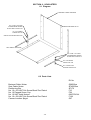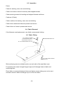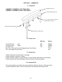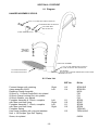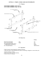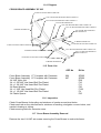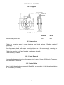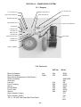
1
RJ MOBILITY LTD.
JEWEL INDOOR POWERCHAIR
TECHNICAL MANUAL
THE PROVEN RELIABLE
INDOOR POWERCHAIR
This Technical Manual will ensure that
the wheelchair is maintained to the
required standard and is for use by
trained personnel only.
This Technical Manual contains important information regarding maintenance of the Jewel
Powerchair thus ensuring its safe operation. Please make sure that you understand all
instructions thoroughly.
It is recommended that maintenance is undertaken at six monthly intervals for a wheelchair
that is in constant daily use.
The safety of the wheelchair user is paramount. If there is any doubt as to the
suitability of re-using existing parts they should be discarded and replaced with
manufacturer approved parts.
User Manuals should be stamped at correct intervals following completion of maintenance
work.
If you fail to understand anything or have any questions concerning maintenance and
operating instructions please contact:
RJ MOBILITY LTD.
Boy Lane, Wheatley
Halifax HX3 5AF
England
Tel: +44(0) 1422 358888
Fax: +44(0) 1422 355924
-1-
CONTENTS
Section
1
2
3
4
5
6
7
8
9
10
11
12
13
14
15
16
17
18
19
USER CATEGORIES
SPECIFICATIONS
POWERCHAIR DIAGRAM
MAINTENANCE CHECKS
TOOL REQUIREMENTS
UPHOLSTERY
ARMRESTS
FOOTRESTS
BRAKES
BACKRESTS
FRAME, LOCKING LINKS AND CROSSBRACES
CASTORS
POWER DRIVE SYSTEM
ELECTRICAL SYSTEM
PROGRAMMABLE CONTROLLER
ELEVATING LEGREST
ARMREST OUTRIGGERS
DETACHABLE TRAY
KERB CLIMBER
-2-
JEWELTECHA.
SECTION 1. USER CATEGORIES
A2
Attendant Controlled. Degree of upper body control to maintain sitting position.
A4
Occupant capable of using one hand to control the powerchair having spatial
awareness, co-ordinated motor skills and sufficient manual dexterity to operate the
controller. The occupant should also have enough upper body control to maintain a
sitting position.
A5
Chin Controlled. Degree of upper body control to maintain sitting position. Capable
of using chin movements to control powerchair. Co-ordinated motor skills.
IMPORTANT
The above identifies the minimum user
characteristics suitable for the Jewel
foldaway powerchair.
-3-
SECTION 2. SPECIFICATIONS
(Dimensions based on seat size 43cm x 43cm (17inch x 17inch)
1.
2.
3.
4.
5.
6.
7.
8.
9.
Overall length
Overall width
Folded length
Folded width
Folded height
Maximum weight
Heaviest Component
Seat plane angle
*Seat depths available
10. *Seat widths available
11.
12.
13.
14.
15.
16.
17.
18.
19.
20.
21.
22.
23.
24.
25.
26.
*
**
Seat height at front
Backrest angle
Backrest height
Footrest to seat
Leg to seat angle
Armrest to seat
Front armrest to backrest
Drive wheel diameter
Tyre Pressures
Maximum load capacity
Turning Space
(a) Spin turn
(b) Between walls
Range ** (30 Amp/hr Battery)
Static Stability
(a) Front
(b) Rear
(c) Side
Maximum forward speed
Maximum stopping distance
Dynamic stability uphill
89cm
(35inch)
54cm
(21inch)
64cm
(25inch)
38cm
(15inch)
55cm
(211/2inch)
50kg
(110 lbs)
21kg
(47 lbs)
o
8.5 (To Ground)
43cm
(17inch)
40cm
(16inch)
43cm
(17inch)
40cm
(16inch)
38cm
(15inch)
36cm
(14inch)
49cm
(19inch)
o
11.5 (To seat perpendicular)
43cm
(17inch) above seat
36-46cm
(14-18inch)
o
85 (From Horizontal)
26-35cm
(9-14inch)
42cm
(17inch)
170mm
(61/2 inch)
N/A (Solid Tyres)
114kg
(18 stone/252 lbs)
185cm
133cm
8.8km
21o
24o
18o
2.2kph
1.5m
18o
(6ft)
(3ft 9inch)
(5.5mile)
(1.4mph)
(5ft)
Note: Please be aware, other sizes may be available to special request.
Note: The range test was conducted in accordance with ISO 7176 Pt 4, capacity is
affected by ambient temperature, user weight, topography, kerb climbing and
battery maintenance.
-4-
SECTION 3. POWERCHAIR DIAGRAM
3.1 JEWEL SELF-PROPELLING POWERCHAIR
1 POWERCHAIR FOLDED
3 BATTERY BOXES
2 CIRCUIT BREAKER
4 ARMREST
t CONTROLLER
5 FOOTREST HANGER
WITH PLATE
6 BATTERY TRAY
-5-
SECTION 4. MAINTENANCE CHECKS
4.1
4.1.1
Open the powerchair, all movements should be free throughout the folding range.
Examine the seat and backrest fabrics for wear, damage or staining.
Examine retaining screws for tightness and general condition. (See Section 6)
4.1.2 Examine armrest pads for wear or damage and tightness of attachment screws.
(See Section 7)
4.1.3 Examine armrest locking assembly for wear and tear and that each armrest is
securely retained. (See Section 7)
4.1.4 Examine footrest hanger for effective locking when fully forward and back. Examine
clamp assembly for secure location of footplate assembly stem tube. Check that
footplates remain vertical when raised. Examine heel loops for damage or
excessive wear and security of attachment. (See Section 8)
4.1.5 Examine the parking brake assemblies for wear, damage or misalignment. (See
Section 9)
4.1.6 Check operation of folding backrest assembly and that it is free to move and locks
into place positively. (See Section 10)
4.1.7. Ensure that tube plugs and ends are fitted to:
Front of seat tubes.
Front of bottom frame tubes.
Armrests front and rear.
Top of backrest tubes.
4.2
4.2.1
4.2.2
4.2.3
4.2.4
4.2.5
4.2.6
4.2.7
4.2.8
4.2.9
Lift the front of the powerchair and rest the backrests on the floor.
Examine the structure of the frame for damage.
Check the pivot points for undue slackness, caused by loose nuts and bolts, or worn
parts. Check that front and rear locking links fully lock. (See Section 11)
Check castors for free rotation of the wheel and the complete assembly. Examine
castors for wear in the bearings. Examine locating spindle for signs of bending, at
the point where it is attached to the frame. (See Section 12)
Examine tyres for uneven wear. Check wheels for free rotation, excessive end float
and rim rock.
Check controller is secure to mounting bracket and that this can be secured to
powerchair by knurled knob/handle on armrest. Examine controller for damage,
particularly any which may allow ingress of fluid. Check joystick knob is secure to
controller, speed control knob and charging socket cover are in place. Move joystick
around quadrant checking for any roughness or stickiness, on release the joystick
must self-centre immediately otherwise braking of the powerchair will be
compromised. Ensure that all LED's are functional so that it can be determined
when controller is switched on/off and that any diagnostic information is accurate.
Check that beau plug on wiring loom fits securely.
The batteries fitted are gel-filled and require no maintenance except to check for
damage and security of connections. See Section 14.7 for comprehensive
instruction.
The battery charger is maintenance free, the only serviceable part is the fuse fitted
to the mains plug. See Section 14.7 for comprehensive instruction.
Ensure the batteries are fully charged.
Drive the Jewel at maximum speed in forward, reverse, left and right directions
checking that the joystick response is uniform.
-6-
4.2.10 Switch off the controller, hold the joystick forward and switch the controller on; the
powerchair must not drive. Release the joystick for two seconds and then the
powerchair will drive normally.
4.2.11 Slowly drive the powerchair up a maximum 1 in 6 gradient and attempt to accelerate.
The powerchair will climb at normal speed.
4.2.12 Reverse down a 1 in 6 slope and check that the powerchair will come to a halt if the
joystick is released.
4.2.13 Whilst driving slowly up the gradient release the joystick and check that the
powerchair does not roll back excessively before the automatic parking brakes come
on.
4.2.14 Check that all cables are connected to the controller, batteries, motors and brakes.
4.2.15 Check that the circuit breaker push buttons on the battery boxes have not sprung
out.
4.2.16 Check that the free wheel devices are releasing and engaging correctly.
4.3.
4.3.1
4.3.2
Check that controller rubber gaiter and switch cover are in good condition.
Check the insulation condition of all cables.
Check that the controller is securely mounted.
-7-
SECTION 5. TOOL REQUIREMENTS
Spanners:
1/4inch Whitworth
10mm AF
8mm AF
7mm Socket and Drive
1/4inch Whitworth
1 5/16inch or 34mm AF
1 5/16inch or 34mm AF
10mm Socket and Driver
10mm Socket and Driver
7/16inch AF
Legrest Clamp
Heel Loops
Parking Brake
Rear Lock Link
Anti-tip Device
Castors
Power Drive System
Power Drive System
Kerb Climber
General
See
See
See
See
See
See
See
See
See
Section
Section
Section
Section
Section
Section
Section
Section
Section
8
8
9
11
11
12
13
13
20
Allen Keys:
3/16inch AF
2/5mm
5mm
5/32inch
Locking Link
Locking Link
Kerb Climber
Kerb Climber
See
See
See
See
Section
Section
Section
Section
11
11
20
20
Pozidrive Screwdriver
Upholstery
See Section 6
Avdel Nutsert Rivet Tool
Upholstery
See Section 6
Loctite Thread Locking
Compound Grade 241
Castors & Wheels
See Section 12/13
Terminal Crimp Tool
to suit 0.5mm to 6.0mm crimps
Power Drive System
See Section 13
Torque Wrench:
Minimum Operating Range
8 lbs/ft (11 Nm)
General
Small Pliers
Light/Soft Head Hammer
Light Oil, e.g. 3 in 1
Wire cutter
Power Drill and 6mm Bit
1/4inch Receptacle wire crimp tool
Snap Rivet tool
General
General
General
General
General
General
General
P&G PP1b programmer & diagnostics device
Control Dynamics programmer & diagnostics device
Advised:
Watt/Minute meter (Current Draw)
-8-
See Section 15
See Section 15
SECTION 6: UPHOLSTERY
6.1 Diagram
BACKREST FABRIC G295/SIZE
No. 10 UNF x 5/8 LONG
COUNTERSUNK SCREW
BLACK ZINC PLATED F138
REINFORCING BARS SF176
No. 10 FLANGED
SCREW CUP F38
CANVAS LOCATION SPIGOT G27
SEAT FABRIC SF453/SIZE
No. 10 UNF x 3/4 LONG
COUNTERSUNK SCREW
BLACK ZINC PLATED F15
No. 10 FLANGED
SCREW CUP F38
No. 10 AVDEL UNF
NUTSERT 09657/01014
6.2 Parts Lists
RJ No
Backrest Fabric Ninian
Seat Fabric Ninian
Reinforcing Bar
No. 10 x 3/4 UNF Csk Screw Black Zinc Plated
No. 10 Flanged Screw Cup
No. 10 UNF Avdel Nutsert
No. 10 x 5/8 UNF Csk Screw Black Zinc Plated
Canvas Location Spigot
-9-
G295/Size
SF453/Size
SF176
F15
F38
09657/01014
F138
G27
6.3 Inspection
Fabric:
Check for staining, wear, tear and stitching.
Check nut inserts in frame for security and stripped threads.
Check securing screws for bending and stripped threads and burrs.
Cushions (if fitted);
Check cushions for staining, wear, tear and stitching.
Check Velcro attachment tabs are present and secure.
Check Velcro on frame is present and secure.
6.4 Fabric Removal
If the Nutserts need replacement, use Avdel recommended tooling.
6.5 Fabric Fitting
No. 10 UNF x 3/4 LONG
COUNTERSUNK SCREW
BLACK ZINC PLATED F15
REINFORCING BAR SF176
No. 10 FLANGED SCREW CUP F38
No. 10 UNF AVDEL NUTSERT
09657/01014
Slide reinforcing bar into stitched section on each side of the seat fabric only.
Fit countersunk screws through flanged cups and fit through holes in fabric and
reinforcing bars.
Place fabric on seat and backrest tubes and tighten screws taking care not to exert
excessive force to flatten the flange cup or cut into the fabric.
-10-
SECTION 7: ARMRESTS
7.1 Diagram
ARMREST PAD M170
ARMREST ASSEMBLY LEFT G244-ASSL
ARMREST ASSEMBLY RIGHT G244-ASSR
5/8x20G ROUND INSERT M5
12x1.1/4 POZI PAN SELF TAPPING
SCREW ZINC PLATED F111
5/8x20G ROUND INSERT M5
ARMREST FRAME G244L
7.2 Parts Lists
Armrest Frame
Left
Armrest Frame
Right
Armrest Pad
No. 12 x 1 1/4 Pozi Pan Self Tapper Screw Zinc Plated
5/8 x 20G Black Round Insert
GZF No
RJ No
632
631
119
G244L
G244R
M170
F111
M5
7.3 Inspection
Check armpad for excess wear or damage.
Check armpad is secured to frame.
Ensure armrest ocates in srear bracket on push handle when fitted to powerchair.
Check armrest lock latch assembly retains armrest to frame assembly.
7.4 Armrest Pad
The armrest pad is secured to the armrest frame with three screws. Removal of the
screws releases the pad. Secure the pad with the attachment screws to refit.
-11-
7.5 Armrest Lock Assembly
To dismantle the assembly, place a screwdriver or similar tool between the starlock washer
(F37) and the lock lever (TSD 1323) and prise apart. Remove the starlock washer, plain
washer (Q5) and the lock lever.
Withdraw the lock pin (TSD 1306) and plunger spring (TSD 1229) from the pin housing in
the armrest location tube.
To assemble, place the plunger spring (TSD 1229) over the lock pin (TSD 1306) and locate
in the pin housing inside the armest location tube.
Pull the lock pin (TSD 1306) through the pin housing using a small pair of pliers and place
a length of tube in the armest location tube or reverse the armrest in the location tube. This
will retain the lock pin inside the pin housing.
Fit the lock lever (TSD 1323) and plain washer (Q5) over the lock pin and press a new
starlock washer (F37) onto the end of the lock pin. Thumb pressure should be sufficient to
fit the starlock washer or alternatively tap with a light hammer.
LOCK PIN TSD1306
PLUNGER SPRING TSD1229
LOCK LEVER TSD 1323
5mm PLAIN WASHER Q5
STARLOCK WASHER F37
RJ No
Starlock Washer
5mm Plain Washer
Lock Lever
Plunger Spring
Lock Pin
F37
Q5
TSD1323
TSD1229
TSD1306
-12-
SECTION 8: FOOTREST
8.1 Diagram
HANGER ASSEMBLY SP231S
5/16x1 1/4 CLAMP BOLT ZINC PLATED F20
5/16 WASHER ZINC PLATED F22
5/16 CLAMP BOLT
ZINC PLATED F21
CLAMP ASSEMBLY M102
HEEL LOOP
ASSEMBLY
TSD 11469/2
FOOTPLATE ASSEMBLY
1/4"x1.1/4" UNF SCREW ZINC PLATED F9
1/4" UNF PLAIN NUT ZINC PLATED F26
7.5" FOOTPLATE M172L/R
8.5" FOOTPLATE M173L/R
NOT SHOWN
No.4x1/4" SELF TAPPING SCREW ZINC PLATED 0456A
SPRING TSD 1349
8.2 Parts List
Footrest Hanger with retaining
clamp assembly M102
Retaining Clamp Assembly
5/16inch x 1 1/4inch Clamp Bolt, zinc plated
5/16inch Clamp Locking Nut, zinc plated
5/16inch Washer, zinc plated
Footplate Assembly 8 1/2inch, complete
with Stem and Heel Loop
Footplate Assembly 7 1/2inch, complete
with Stem and Heel Loop
Footplate Spring
Heel Loop complete with nuts and washers
No.4 x 1/4 Pozipan Type Self Tapping
Screw, zinc plated
-13-
GZF No
RJ No
Right
Left
113
114
Left
Right
Left
Right
111
110
111
110
SP261S/R
SP261S/L
M102
F20
F21
F22
SP356
SP357
SP358
SP359
TSD1349
TSD11469/2
112
0456A
8.3 Inspection
Check that footrest assembly locks into position.
Apply light grease to swivelling end.
Ensure that stem clamp holds footplate in position.
Ensure that footplate will remain in vertical position when required.
Ensure no sharp edges/burrs which could injure user.
8.4 Footrest Removal
Remove the footrest assembly from the powerchair by lifting and rotating the hanger
section. Loosen the clamp with a 1/4inch Whitworth spanner and slide the stem assembly
out.
8.5 Footrest Fitting
Re-assemble heel loop to footplate and tighten nuts to 10 lbs/ft (13.5Nm). Insert footplate
stem into hanger tube and tighten clamp to 35 lbs/ft (47Nm).
The footplate should remain in the vertical position when required. This is maintained by
semi-elliptic spring acting between the footplate and the pivot tube. This does not normally
require maintenance.
-14-
SECTION 9: BRAKES
9.1 Diagram
BRAKE ASSEMBLY 300-19-11
RETURN SPRING ZINC
PLATED SF233L
233R
BLACK KNOB
BRAKE HANDLE SF172 LP
SF172 RP
1/16" x 1/2" SPLIT PIN ZINC PLATED F50
10/32 UNF NYLOC NUT
ZINC PLATED F24
BRAKE PIVOT SF 173P
2BA WAVEY WASHER COPPER F29
1/16" x 1/2" SPLIT PIN ZINC PLATED F50
BRAKE LEVER
2BA WAVEY WASHER COPPER F29
SF171R
SF171L
10/32x5/8 UNF HEX HEAD
SCREW ZINC PLATED F13
10/32x5/8 UNF HEX HEAD
SCREW ZINC PLATED F13
1/4 UNF PLAIN NUT
ZINC PLATED F26
2BA WAVEY WASHER COPPER F29
10/32 UNF NYLOC NUT
ZINC PLATED F24
THREAD PROTECTOR
199462
2BA WAVEY WASHER COPPER F29
1/4 UNF PLAIN NUT
ZINC PLATED F26
BRAKE SHOE SF174A
9.2 Parts List
GZF No
Brake Assembly
Brake Assembly
Brake Handle
Brake Handle
Black Ball Knob
Brake Pivot
Brake Lever
Brake Lever
Brake Shoe
Return Spring Zinc Plated
Return Spring Zinc Plated
1/16x1/2 Split Pin Zinc Plated
10/32x5/8 UNF Hex Head Screw Zinc Plated
-15-
Left
Right
Left
Right
Left
Right
Left
Right
258
259
RJ No
300-19-11L
300-19-11R
SF172LP
SF172RP
KB5-125
SF173P
SF171L
SF171R
SF174A
SF233L
SF223R
F50
F13
9.2 Parts List Cont'd
GZF No
1/4 UNF Plain Nut Zinc Plated
2BA Wave Washer Copper
10/32 UNF Nyloc Nut Zinc Plated
Thread Protector
RJ No
F26
F29
F24
199462
9.3 Inspection
Check ball knob for security.
Check levers for distortion.
Check brazed joints for cracks.
Check pivot shafts for distortion.
Replace pivot bolts if necessary due to excessive wear.
Ensure no oil/grease on brake pad.
9.4 Brake Assembly Removal
Remove the two 1/16inch Split Pins from the Brake Pivot shaft and Brake Lever shaft.
Remove the 2BA Wavey Washers and slide the brake assembly from the frame.
9.5 Brake Assembly Fitting
Fit the Brake Pivot and Brake Lever shafts through the bushes on the frame. Fit the 2BA
Wavey Washers on each shaft and fit two new Split Pins. Retain the Split Pins in the holes
by bending the ends apart using small pliers. Replace with a new Return Spring if
necessary.
Ensure pivot bolts are not over tightened as this will lead to fracture of the brazed tabs on
the brake handle.
Lubricate with light oil.
9.6 Brake Adjustment
The Brake Shoe position can be adjusted by loosening the lock nut and repositioning the
shoe. The nuts should be adjusted to allow an operating force at the knob to be between
10lbf to 13lbf (44 to 58 N) with the tyres inflated to the correct pressure (50psi/340
KiloPascals).
-16-
SECTION 10: BACKRESTS
10.1 Diagram
BACKREST ASSEMBLY LEFT G223
BACKREST ASSEMBLY RIGHT G224
BLACK PLASTIC BUNG M14
No. 10 AVDEL NUTSERT
09657/01014
BACKREST G246
1/4x1.3/4 UNF HEX HEAD
BOLT ZINC PLATED F11
BLACK PLASTIC BUNG M14
3/16x1 SPRING PIN
BLACK ZINC PLATED F43
1/4 BRASS WASHER F30
1/4 UNF TYPE P NYLOC NUT
ZINC PLATED P90
BLACK PLASTIC BUNG M14
SLIDING PEG HANDLE G244
PLUNGER STOP SF194
SLIDING PEG SPRING F71
SLIDING PEG G28
3/16x1 SPRING PIN
BLACK ZINC PLATED F43
-17-
10.2 Parts List
GZF No
Backrest Assembly
Backrest Assembly
Backrest Frame
Backrest Frame
Sliding Peg
Sliding Peg Handle
Black Plastic Bung
Knurled Plastic Nut
3/16x1 Spring Pin Black Zinc Plated
1/4 Brass Washer
1/4 UNF Type P Nyloc Nut Zinc Plated
Sliding Peg Spring
Plunger stop
1/4 x 1 3/4 UNF Hex Head Bolt Zinc Plated
No. 10 Avdel Nutsert
Left
Right
Left
Right
335/965
336/966
RJ No
G223
G224
G246L
G246R
G28
G244
M14
F47
F43
F30
P90
F71
SF194
F11
09657/01014
10.3 Inspection
Check each backrest for evidence of bending.
Check each backrest for evidence of cracking through nutsert holes.
Check for free movement of the plunger. Lubricate with light oil.
Check that the plunger locates in the hole on the side frame.
Ensure Nyloc nut still grips thread.
10.4 Backrest Removal
Unscrew 5 off No. 10 UNF countersunk screws holding the backrest fabric to the backrest
assembly.
Unscrew the 1/4 UNF nut and withdraw the bolt.
10.5 Push Handle Fitting
Insert the 1/4 UNF bolt through the backrest and hinge plates. Replace the washer and
tighten the Nyloc nut until the backrest pivots freely without excessive free-play.
Fit the 5 off No. 10 UNF countersunk screws to hold the backrest fabric to the backrest
assembly.
-18-
SECTION 11: FRAME, LOCKING LINKS AND CROSSBRACES
11.1 Diagram
SIDE FRAME ASSEMBLY LEFT 300-19L
SIDE FRAME ASSEMBLY RIGHT 300-19R
No. 10 AVDEL NUTSERT
09657/01014
SIDE FRAME RIGHT 300-19R
ARMREST LOCK
ASSEMBLY
3/4 SQUARE BLACK
BUNG M11
3/4 SQUARE BLACK
BUNG M11
SIDE FRAME LEFT 300-19L
1 3/8x5/8 BLACK
BUNG M195
11.2 Parts List
RJ No
Side Frame Assembly
Side Frame Assembly
3/4 Square Black Plastic Bung
1 3/8x5/8 Black Plastic Bung
No. 10 Avdel Nutsert
Left
Right
G1
G2
M11
M195
09657/01014
11.3 Inspection
Check Armrest Locking assembly operates effectively.
Check each tab on the sideframes for evidence of bending, elongation or worn holes, and
cracks in brazing or tubing.
Check tube inserts are fitted correctly.
Examine frame for damage.
-19-
11.4 Diagram
CROSS BRACE ASSEMBLY SF 205
1/4 UNF NYLOC NUT ZINC PLATED P90
1/4x1 5/8 UNF HEX HEAD BOLT ZINC PLATED F10
1/4x1 3/4 UNF HEX HEAD BOLT ZINC PLATED F11
6mm NYLON SPACER F65
1/4x1 UNF HEX HEAD BOLT ZINC PLATED F139
1/4x1 1/8 UNF HEX HEAD BOLT ZINC PLATED F4
1/4 BRASS WASHER F30
1/4x1 5/8 UNF HEX HEAD BOLT
ZINC PLATED F10
1/4 BRASS WASHER F30
1/4 UNF NYLOC NUT ZINC PLATED P90
1/4 UNF NYLOC NUT ZINC PLATED P90
1/4x1 UNF HEX HEAD BOLT ZINC PLATED F139
1/4 BRASS WASHER F30
1/4x1 3/4 UNF HEX HEAD BOLT
ZINC PLATED F11
1/4 UNF NYLOC NUT ZINC PLATED P90
1/4 BRASS WASHER F30
11.5 Parts List
Cross Brace Assembly 17" Complete with Fasteners
Cross Brace Assembly 15" Complete with Fasteners
1/4 UNF Nyloc Nut
1/4 x 1 5/8 UNF Hex Head Bolt Zinc Plated
1/4 x 1 3/4 UNF Hex Head Bolt Zinc Plated
1/4 Brass Washer
1/4 x 1 UNF Hex Head Bolt Zinc Plated
1/4 x 1 1/8 UNF Hex Head Bolt Zinc Plated
1/4 Plastic Spacer
GZF No
RJ No
006
007
SF205
SF206
P90
F10
F11
F30
F139
F4
F65
11.6 Inspection
Check Cross Braces for bending and evidence of cracks around pivot holes.
Check each tab on the side frames for evidence of bending, elongation or worn holes, and
cracks in brazing or tubing.
Check securing bolts for excessive wear.
11.7 Cross Brace Assembly Removal
Remove the two 1/4 UNF set screws securing the Cross Braces to each side frame.
-20-
11.8 Cross Brace and Locking Link Assembly Fitting
Fit the two 1/4 UNF set screws securing the Cross Braces to each side frame.
Tighten until the Cross Brace is just securely held, then loosen the nut half a turn.
The Cross Brace Assembly must be free to move without binding, but show no signs of
excessive free play. Lubricate with light oil, eg 3 in 1. Overtightening of Cross Brace
Assembly will prevent the pivoting action and will lead to fracture of the tab on the side
frame.
11.9 Diagram
1/4 BRASS WASHER F30
1/4 UNF NYLOC NUT ZINC PLATED P90
1/4x1 UNF SOCKET CAP SCREW
ZINC PLATED F137
1/4 BRASS WASHER F30
11.9 Parts List
Front Locking Link Assembly
Front Locking Link Assembly
1/4 x 1 UNF Socket Cap Screw Zinc Plated
1/4 UNF Nyloc Nut Zinc Plated
1/4 Brass Washer
6mm Nylon Washer
17"
15"
GZF No
RJ No
109
005
SF 207F
SF 208F
F137
P90
F30
F86
11.10 Inspection
Check Locking Links for security of thumb catch and correct operation. The locking link
should open/close easily and the thumb catch must hold securely in the open position so
that the powerchair will not fold under load.
Check each tab on the side frame for evidence of bending, elongation or worn holes, and
cracks in the brazing or tubing.
-21-
11.12 Locking Link Assembly Removal
Remove the 1/4 UNF Socket Cap Screw securing the Locking Link to each side frame.
11.13 Locking Link Assembly Fitting
Fit the two 1/4 UNF Socket Cap Screws to secure the Locking Link assembly to each side
frame. Tighten until the Locking Link is just securely held, then loosen the nut half a turn.
The Locking Link Assembly must be free to move without binding, but no signs of excessive
free play. Lubricate with light oil, eg 3 in 1. Overtightening of Cross Brace Assembly will
prevent the pivoting action and will lead to fracture of the tab on the side frame.
-22-
SECTION 12: CASTORS
12.1 Diagram
190mm WIDE PROFILE M51
M14 x 22 LONG
140 SWIVEL RADIUS
190
235 EFFECTIVE HEIGHT
10
23.95mm A/F
HEXAGON
45
10
12.2 Parts List
190mm wide profile MCP
GZF No
RJ No
557
M51
12.3 Inspection
Check for excessive wear in crown bearings and wheel spindle. Replace castor if
necessary.
Check for condition of stud which screws into frame.
View frame and check both castor mounting tubes are at the same angle, checking for
frame distortion due to impact damage, replace if necessary.
Check tyre security to rim and for splits, cracking or damage.
Check security of castor.
12.4 Castor Removal
Unscrew the hexagon at the top of the castor swivel, using a 24mm (15/16inch) AF spanner,
until the castor is removed.
12.5 Castor Fitting
Apply Loctite thread locking compound Grade 241, or equivalent, to the thread and tighten
to 30-35 lbs/ft (40-47 Nm).
-23-
SECTION 13: POWER DRIVE SYSTEM
13.1 Diagram
1
/4x11/4 HEX BOLT F7
M6x10 HEX SCREW F95
STUB AXLE D9L
SPRING WASHER F33
WAVE WASHER F65
HEX NUT D9
BRONZE BUSH M89
TAB WASHER M158
DRIVE COUPLING M155
SPACER D23
LARGE NYLON
WASHER F67
SMALL NYLON
WASHER F66
DRIVE COLLAR M159
MOTOR E94
SPRING M156
SPACER M157
WHEEL ASSEMBLY
13.2 Parts List
GZF No
Motor & Gearbox
Motor & Gearbox
Motor Brush Replacement (Not Shown)
Wheel Assembly
Stub Axle
Hex Nut
Drive Coupling
Spring
Bronze Bush
Drive Collar
Spacer
Nylon Washer (Large)
Nylon Washer (Small)
1/4 x 1 1/4 UNF Hex Head Bolt Zinc Plated
-24-
Left
Right
624
623
314
958
959
320
962
960
RJ No
E95L
E95R
G297/ASS
D9L
D9
M155
M156
M89
M159
M157
F67
F66
F7
M74
Tab Washer
M6x10 Hex Head Screw Zinc Plated
10mm Spacer
1/4 Spring Washer
Wavey Washer
Clamp Bolt
Clamp Washer
Clamp Nut
Knob
M158
F95
D23
F33
F65
F20
F22
F21
13.3 Inspection
The motor/gearbox/wheel assembly is mounted securely to the motor, which should be
securely attached to the side frame.
Check the tyre for excessive wear and the wheel for signs of damage.
Check for rim-rock which will indicate worn bearings and/or stub axle. Maximum allowable
is 5mm total.
Check for end-float which will indicate worn thrust washers. Maximum allowable is 3mm.
Check that the free-wheel mechanism engages and dis-engages freely and that the drive
dogs do not have rounded corners.
Check the drive securing bolt in the end of the drive shaft is tight and the tab washer is bent
up for security.
Check the motor loom for damage and that the plug wiring is secure.
Check for unusual noises such as whining or rubbing which might indicate that the solenoid
brake is touching the cowl.
Move the joystick around the quadrant and check that when released it self-centres and the
brakes operate.
An audible click will be heard from each motor when the brakes are applied and released.
Raise the rear of the powerchair and support on suitable stands. Engage the drive
mechanism and move the joystick around the quadrant to simulate forward, reverse and
turning. Observe the wheel rotation to ensure it mirrors joystick movement and check for
any wheel/tyre distortion.
13.4 Power System Removal
If it is required to remove the complete drive assembly as one unit the following procedure
applies.
Support the rear of the powerchair on suitable stands and disconnect the motor wiring loom
from the main loom. Using 7/16 AF spanners release the four nuts/bolts which attach the
mounting plate to the side frame. Withdraw the bolts and remove the assembly.
-25-
13.5 Power System Replacement
Replacement is a straightforward reversal of the above procedure. The attachment nuts
and bnolts should be renewed and tightened to a torque of 35 lbs/ft (47Nm).
13.6 Motor Brake Removal
IMPORTANT
Investigate warranty status before proceeding.
Failure to do so may invalidate your warranty.
Motor and gearbox maintenance is limited to
complete assembly replacement except replacing
motor brakes and brushes.
Check Brake and Motor functions operate
correctly after any maintenance when completed.
Remove the motor cowl by releasing the two self-tapping screws and lifting off the motor
cowl, being careful to feed the loom through the grommet so that no force is applied to the
wiring.
Disconnect the motor plug and brake wires and cut off the crimped spade connectors.
From inside the cowl pull the two brake wires through from the motor loom sheath. Using
Allen key remove the two securing bolts on the top of the brake assembly. The brake
asembly can now be removed.
13.7 Motor Brake Removal
The brake is not serviceable so a new one must be fitted. Place on top of the motor and
secure with Allen bolts after applying small quantity of thread locking compound. Torque to
10lbs/ft (13.5Nm). Feed the two brake wires through the grommet in the cowl alongside
the motor loom and refit the cowl. Cut off the brake wires to the required length and fit new
spade connectors. Tape the brake wires to the outside of the motor loom to give complete
protection. Reconnect the motor to the main loom and test.
13.8 Motor Brush Removal & Replacement
Disconnect the motor loom from the main loom, release the two self-tapping screws which
hold the motor cowl and slide the motor cowl along the motor loom, taking care not to apply
any force to the wiring.
The brushes are located vertically either side of the brake assembly. They are joined
together by a wire and by gently pulling this will release the brushes.
To replace, press gently into the slots and position wire so that it is not in contact with the
brake assembly. Refit the motor cowl taking care not to trap any wiring. Re-connect the
motor loom and test.
-26-
On some later model powerchairs cartridge brushes are fitted which require no dismantling.
These are accessed from the outside of the motor and are removed by unscrewing the caps
situated below the rim of the motor cowl.
13.9 Drive Coupling Removal and Replacement
If it is only necessary to remove part of the drive assembly the following procedure applies.
Support the rear of the powerchair on suitable stands and disconnect the motor wiring loom
from the main loom. Bend the tab washer (M158) away from the bolt head and using a
10mm spanner remove the drive securing bolt (F95). This is made easier if the drive is
engaged.
The drive components can now be withdrawn from the motor drive shaft and care should
be taken not to lose any parts.
Examine the components for damage or wear as indicated from the previous checks. If the
wheel bushes need replacing these can be removed by the use of a soft drift and hammer.
Replacement of wheel bushes requires the use of a press to prevent burring the edges of
the bushes.
If it is necessary to replace the stub axle (D9L) the motor will require removal from the
mounting plate. Using a 7/16 AF spanner release the three retaining bolts and withdraw,
being careful not to lose the spacers. The motor can now be removed by sliding the drive
shaft out of the stub axle. Using spanners 34mm AF and 35mm AF remove the stub axle.
Replace the stub axle (D9L), apply thread locking compound and tighten to 35 lbs/ft (47Nm)
torque. Refit the motor to the mounting plate, insert spacers and tighten bolts to 10 lbs/ft
(13.5Nm) torque.
Re-assemble the thrust washers, metal wavy (F65) first, plain nylon second. Fit the wheel
and small plain nylon washer. Fit the drive collar (M159), cup washer (M157), spring
(M156) and drive dog (M155). Use a new tab washer (M158) and bolt (F95). Apply
threadloc compound (Grade 66) to the bolt threads and tighten 10 lbs/ft (13.5Nm) torque.
Finally bend the tabs up ensuring that they are in contact with the bolt head.
IMPORTANT
Motor and gearbox maintenance is limited to
complete assembly replacement except
replacing motor brakes and brushes.
-27-
SECTION 14: ELECTRICAL SYSTEM
14.1 Diagram
YELLOW
G91 YELLOW
G91 RED
G91 BLACK
F F
F F
9 BRAKE
YELLOW
BROWN
R R
B B
1 RH MOTOR –
2 RH MOTOR +
BLUE
GREY
ORANGE
F
F
G202-11 RED
BLACK
RH MOTOR
G91 BLACK
B R
B R
–
+
5 BATTERY
+
6 BATTERY
7 BATTERY
+
–
8 BATTERY
–
CONTROL BOX
CONNECTOR
R B
R B
G91 RED
B R
B R
F
F
G91 YELLOW
G91 YELLOW
G202-10 YELLOW
RED
3 LH MOTOR
4 LH MOTOR
CIRCUIT BREAKER
NOTE:
R & B REFER TO CONNECTOR
COLOURS RED & BLACK
BATTERY 1
BATTERY 2
LH MOTOR
14.2 Parts List
Main Wiring Loom
Battery Loom
Motor Assembly
Motor Assembly
30 Amp/Hr Battery
Circuit Breaker
Left
Right
-28-
GZF No
RJ No
624
623
620
G202
201/18
E94LL
E94R
E75/30amp/hr
14.3 Electerical System Inspection
A full function test of the powerchair should be carried out to determine any major faults
which will be indicated by flashing lights on the controller. By reference to Section 15 the
fault may be diagnosed.
Check the condition of the main wiring loom for damage. Check the beau plug connector
which should be tight fitting so that it is not easily dislodged in use.
Check the plugs connecting the main loom to the motor and battery looms should be
examined to ensure that the wiring is secure with no evidence of chafing or damage. The
contacts inside the plugs should be inspected for prominence to ensure good contact is
made.
A stall-test should be performed to check that the circuit breakers function correctly. Place
the powerchair with the castor wheels against a solid object and ensuring the drive wheels
do not spin, push the joystick forward. After a short period the power to the motors will be
cut by the operation of the circuit breakers.
Reset the circuit breakers by pushing in the buttons which are found on the battery boxes.
14.4 Wiring Loom Removal and Replacement
Disconnect the beau-plug from the rear of the controller. Disconnect the motor and battery
loom plugs from the main loom and withdraw the main loom.
To replace, feed the main loom underneath the seat from the same side as the controller.
Connect the motor and battery loom plugs to the main loom and re-connect the beau plug
to the controller. The application of petroleum grease to the contacts will assist in assembly
and offer protection against moisture.
14.5 Battery Loom Removal and Replacement
There are two distinct looms fitted depending on which battery box is being worked upon.
When viewed from the rear of the powerchair the front battery box has a loom with one grey
plug, the rear battery box has a loom with two plugs - one grey and one black.
Remove the rear battery box from the powerchair and remove the lid. The connections to
the battery terminals should be removed and then pull off the connections to the circuit
breaker.
Re-fitment is a reversal of the above. Note that the grey plug is positioned to the front and
the black plug exits from the rear.
Remove the front battery box from the powerchair and remove the lid. The connections to
the battery terminals should be removed and then pull off the connections to the circuit
breaker.
Re-fitment is a reversal of the above. Note that the grey plug exits from the rear of the lid.
-29-
14.6 Circuit Breaker Removal and Refitment
Follow the above procedure for removal of the battery wiring looms. When the wiring loom
has been pulled off the circuit breaker it can be removed from the battery box lid. Grasp
the circuit breaker with one hand and with a pair of pliers grip the serrated nut on the
outside and release.
Re-fitment is a reversal of the above.
14.7 Batteries and Battery Charging
The batteries and battery charger require no maintenance but a check for function should
be carried out.
14.7.1 Battery Inspection
Remove the batteries from the powerchair and from their containers. It should be noted if
the battery connections are tight.
Examine the batteries for any damage. Beware : acid-gel may leak from a damaged
battery which is highly corrosive. Any contamination should be washed off immediately with
copious amounts of clean water. Seek medical advice if any irritation persists.
The battery condition should be checked. Ideally this should be done using specialised
equipment such as a discharge tester. However this may take several hours as the battery
will be left in a discharged state and will require re-charging.
At the least a 'drop-test' should be performed using a simple car battery load tester. This
measures internal resistance and it is known that the internal resistance of a battery
increases as the battery ages and performance decreases.
This type of test doeso not provide an assurance that the battery is fully capable of
delivering its rated active energy and is dependent on the experience of the test engineer.
All testing should be performed on fully charged batteries and the test engineer should
satisfy himself that this is so.
14.7.2 Battery Replacement
If the batteries are deemed fit for further use they may be re-fitted to the powerchair.
Replace in their containers and smear the terminals with petroleum grease. Ensure the
connections are tight and the battery wiring looms are undamaged. Refit to the powerchair.
14.7.3 Battery Charger Inspection
The charger is maintenance free but a check for function should be made.
Check for damage to the charger and to the mains and charging cables. Ensure the
ventilation slots are clear.
Connect the charger to the powerchair and then to the mains. Switch on the mains and the
yellow light should light up immediately, followed shortly afterwards by the orange 'charging'
indicator. The yellow 'bulk charge complete' light will illuminate between 4 and 11 hours
after commencement of charging, depending on the state of discharge of the batteries. The
green 'charging complete' will illuminate between 8 and 14 hours after commencement of
charging, depending on the state of disdcharge of the batteries.
Full operating and use instructions are given in the battery charger's User Manual supplied
with the powerchair.
-30-
SECTION 15: PROGRAMMABLE CONTROLLER
15.1 Diagram
CONTROL DYNAMICS
DX SYSTEM
ON/OFF SWITCH
CONTROL DYNAMICS
DL CONTROLLER
PENNY & GILES
PILOT CONTROLLER
JOYSTICK
SPEED LIMITER
JOYSTICK
BATTERY GAUGE
BATTERY GAUGE
JOYSTICK
ON/OFF
SWITCH
ON/OFF SWITCH
BATTERY GAUGE
REMOTE SOCKET
CHARGING SOCKET
SPEED LIMITER
SPEED
LIMITER
CHARGING
SOCKET
CHARGING SOCKET
PROGRAMMER
SOCKET
PROGRAMMER
SOCKET
FRONT
REAR
POWER
SOCKET
CONTROLLER MOUNTING
CONTROLLER MOUNTING PLATE G66A
CONTROLLER EXTENSION G67A
PILOT CONTROLLER E109
CONTROLLER MOUNTING PLATE G278A
1/4x1.1/8 UNF HEX HEAD SCREW
ZINC PLATED F4
M5x8 POZI PAN SCREW
ZINC PLATED F18
CONTROLLER EXTENSION
A03/134
BLACK PLASTIC BUNG M8
CONTROL DYNAMICS DL
CONTROLLER E123
M5x8 POZI PAN SCREW
ZINC PLATED F18
BLACK PLASTIC BUNG M8
1/4 UNF NYLOC NUT ZINC PLATED P90
-31-
15.2 Parts List
GZF No
RJ No
Penny & Giles Pilot Controller
Controller Extension
Controller Mounting Plate
P&G Pilot Controller
1X1 1/8 UNF Hex. HD Screw Zinc Plated
1/4 UNF Nyloc Nut Zinc Plated
M5x8 Pozipan Screw Zinc Plated
Black Plastic Bung
621
A03/134
G278A
E108
F4
P90
F18
M8
Control Dynamics DL Controller
Controller Extension
Controller Mounting Plate
Control Dynamics DL Controller
M5x8 Pozipan Screw Zinc Plated
Black Plastic Bung
G67A
G66A
E123
F18
M8
15.3 Inspection
Check the M5 Pozipan screws are tight and hold the controller securely to the Controller
Extension.
Check the condition of the Black Plastic Bungs.
15.4 Programmable Controller Removal
Penny & Giles Pilot Controller
Remove the two M5x8 Pozipan screws which secure the Controller to the Controller
mounting plate.
Release the two 1/4 UNF Nyloc nuts from the underside of the Controller Extension and
remove the 1/4 x 1 1/8 UNF Bolt holding the Controller Mounting Plate.
Control Dynamic DL Controller
Remove the four M5x8 Pozipan Screws which secure the Controller to the Controller
Extension.
Release the four M5x8 Pozipan Screws which secure the Controller to the Controller
Mounting Plate.
15.5 Programmable Controller Replacement
Follow 15.3 in reverse.
-32-
15.6 Inspection
Each controller acts as a diagnostic system and if a fault is detected the battery gauge will
flash to a pre-determined sequence.
Control Dynamic DL Controller
The three colour illuminated display onthe top surface of the DL Controller acts as both a
fuel gauge and a warning gauge. When all lights are on the batteries are fully charged. As
the power is used the green lights and then amber lights will go out. When only the red
lights are left on the batteries will require recharging. If a fault is detected the illuminated
display will flash. To determine the fault count the number of flashes and refer to the
following table:
1
2
3
4
5
6
7
Low battery
High battery
Left Motor
Right Motor
Left or Right Park Brake
Controller fault
Motor stalled or joystick
out of neutral/time out
You may need to charge your batteries
Possible charger fault
There may be a fault or a loose connection
There may be a fault or a loose connection
There may be a fault or a loose connection
Please contact Customer Services Switch the controller off then back on again
Control Dynamic DX System
The three colour illuminated display on the top surface of the DL Controller acts as both a
fuel gauge and a warning gauge. When all lights are on the batteries are fully charged. As
the power is used the green lights and then amber lights will go out. When only the red
lights are left on the batteries will require recharging. If a fault is detected the illuminated
display will flash. To determine the fault count the number of flashes and refer to the
following table:
1
2
3
4
5
6
7
8
9,10
11
12
Limp Mode
Accessory Fault
Left Motor
Right Motor
Left Park Brake
Right Park Brake
Low Battery
Over Voltage
Limp Mode
Motor stalled or joystick
out of neutral/time out
Module Mismatch
Turn the controller off & then on again
Possible remote joystick fault
There may be a fault or a loose connection
There may be a fault or a loose connection
There may be a fault or a loose connection
There may be a fault or a loose connection
You may need to charge your batteries
Check the battery circuit for loose connection
Turn the controller off & then on again
Switch the controller off then back on again
Check the compatibility of modules
-33-
Pilot Controller
The battery gauge is a 10 segment illuminated display which indicates if the controller is
turned on and also gives the status of the battery, the controller and the powerchair
electrical system.
Red, Yellow and Green bars lit
Red and Yellow bars lit
Red bars only lit
Rapid flashing of bars
Ripple up and down of bars
Fault Type
The number of flashing
bars indicate the possible
area of fault.
Battery charger; controller and electrical
system OK
Charge battery if possible; controller and
electrical system OK
Charge batteries AS SOON AS POSSIBLE;
controller and electrical system OK
Indicates a fault in the controller or
electrical system. See table below for fault
diagnosis.
Joystick displaced at turn on
GREEN
GREEN
GREEN
YELLOW
YELLOW
YELLOW
YELLOW
RED
RED
RED
Description
High battery voltage
Solenoid brake faulty
Possible controller fault
Possible joystick fault
Charger connected
Right motor wiring fault
Right motor disconnected
Left motor wiring fault
Left motor disconnected
Low battery voltage
General
Check that the insulation of the connecting cables is in good condition and that the
connectors are fully mated.
Check to ensure the control system is securely mounted.
-34-
SECTION 16: ELEVATING LEGREST
16.1 Diagram
ELEVATING LEGREST
ASSEMBLY SP333
1/4 UNF X 1 7/8 HT BOLT
ZINC PLATED F12
1/4 X 18G PLASTIC PLUG M9
1/4 UNF NYLOC NUT
ZINC PLATED P90
LEGREST STEM SF120
LEGREST CARRIER
BRACKET SF95
ELEVATING ROD
SF123
LEGREST TRIGGER
SPRING SF234
STEM SWIVEL TUBE SF88
LEGREST TRIGGER
SF122
CALF PAD
TSD10241
LEGREST TRIGGER
BRACKET SF121
1/4 UNF NYLOC NUT
ZINC PLATED P90
CLAMP ASSEMBLY M102
1/16 x 1/2 SPLIT
PIN F153
1/4 UNF X 1 1/4 HT BOLT
ZINC PLATED F7
1/4 X 18G PLASTIC PLUG M9
BOTH ENDS
1/4 X 18G PLASTIC PLUG M9
CALF PAD SWIVEL
BRACKET SF89
1/4 UNF NYLOC NUT
ZINC PLATED P90
1/4 UNF X 1 7/8 HT BOLT
ZINC PLATED F12
16.2 Parts List
GZF No
Legrest Assembly Complete
- Left
- Right
RJ No
SP333L
SP333R
SP234
SF123
SF122
SF121
SF120
SF95
SF89
SF88
TSD10241
M102
P90
F12
F7
F153
M9
Legrest Trigger Spring
Elevating Rod
Legrest Trigger
Legrest Trigger Bracket
Legrest Stem, Left or Right
Legrest Carrier Bracket, Left or Right
Calf Pad Swivel Bracket
Stem Swivel Tube, Left or Right
Calf Pad MCP
Clamp Assembly
1/4 UNF Nyloc Nut, zinc plated
1/4 UNF x 1 7/8 HT Bolt, zinc plated
1/4 UNF x 1 1/4 HT Bolt, zinc plated
1/16 x 1/2 Split Pin
1/4 x 18G Plastic Plug
-35-
16.3 Inspection
Check
Check
Check
Check
Check
heel loop for security. Nuts should be tightened to 10 lbs/ft (13 Nm).
pivot bolt for wear.
calf pad for wear/damage.
adjustment rod for bending.
footplate maintains set position.
16.4 Elevating Legrest Removal
Remove the footrest assembly from the powerchair by lifting and rotating the hanger
section.
Release stem clamp and withdraw footplate and stem.
Release nuts securing calf pad and remove.
Release pivot bolt and separate elevating section from swivelling section.
Remove rubber end cap from adjustment rod, and holding trigger withdraw rod.
16.5 Elevating Legrest Fitting
Assemble elevating section to swivelling section. Use new pivot bolt, if necessary.
Slide adjustment rod through bracket and trigger ensuring spring is positioned to force
trigger forward. Replace rubber end cap.
Assemble calf pad to bracket. Tighten nuts to 10 lbs/ft (13 Nm).
Insert footplate stem into tube and tighten clamp to 35 lbs/ft (47 Nm).
Apply light grease to swivelling end and insert into castor tube.
Ensure no grease/oil on adjustment rod or it will cause slippage.
-36-
SECTION 17: ARMREST OUTRIGGERS
17.1 Diagram
1/4x7/8 HEX HEAD BOLT
ZINC PLATED F3
BLACK PLASTIC BUNG M17
ARMREST OUTRIGGER
G273
OUTRIGGER SPACER G274
1/4 UNF NYLOC NUT P90
ARMREST OUTRIGGER
BACKREST LOCATION G275
1/4x1 1/8 HEX HEAD BOLT
ZINC PLATED F4
1/4x7/8 HEX HEAD BOLT
ZINC PLATED F3
17.2 Parts List
GZF No
Armrest Outrigger Socket Assembly
- Left
Armrest Outrigger Socket Assembly
- Right
Armrest Outrigger Rear Location Assembly
Armrest Outrigger Socket
Armrest Outrigger Backrest location
Outrigger Spacer
1/4 x 7/8 UNF Hex Head Bolt Zinc Plated
1/4 x 1 1/8 UNF Hex Head Bolt Zinc Plated
1/4 UNF Nyloc Nut Zinc Plated
7/8 Black Plastic Bung
-37-
RJ No
G273/ASS/L
G273/ASS/R
G275/ASS
G273
G275
G274
F3
F4
P90
M17
17.3 Inspection
Check for damage to sockets.
Ensure spacers are fitted.
Check screw threads are not stripped particularly on backrest bracket.
Ensure armrests locate in backrest bracket when fitted to powerchair. Check for bending
of armrest tube at insertion point.
17.4 Dismantling
Release nuts securing sockets to side frame and remove.
Slide sockets away from frame and remove spacers.
Release extension bracket from backrest.
17.5 Fitting
Replace spacers in side frame sockets.
Slide outrigger sockets into position and insert bolts.
Tighten nuts to 10 lbs/ft (13 Nm).
Hook rear bracket over backrest loop and tighten screw to 3 lbs/ft (4 Nm).
-38-
SECTION 18: DETACHABLE TRAY
18.1 Diagram
TRAY ASSEMBLY GWD 837
ARMREST PAD M170
12x1.1/4 SELF TAPPING SCREW
ZINC PLATED F111
TUBE PLUG
M5
ARMREST G244L/R
KNOB M74KK
TRAY BRACKET
296/32
18.2 Parts List
GZF No
Tray Bracket
- Left
- Right
RJ No
296/32/L
SF316R
Tray
Tray Bracket
837
838
18.3 Inspection
Check for damage to the tray, particularly for wooden splinters.
Check security of attachment screw 'B' and check tray attachment screws for security.
Check all adjustment knobs are present, undamaged and hold tray at the required position.
-39-
18.4 Assembly
Remove plastic bung 'A'. Remove screw 'B'.
Insert 3/4 inch diameter tube item 'C' over end of armrest tube. Line up holes in item 'C'
with screw hole in armrest tube. Insert screw 'B' and retighten.
Insert the tubular mounting stems complete with stem brackets supplied with the tray, into
the armrest stem assembly with the horizontal extensions of the mounting stems projecting
forward.
Place the tray symmetrically on the stem brackets, ensuring that the flat plates are located
between the two guide strips on the under-side of the tray.
Mark through the screw holes in the stem brackets.
Remove the tray and brackets from the powerchair and secure brackets to tray with screws
supplied.
Refit tray assembly to the powerchair. Screw the two loose knurled knobs supplied with the
tray assembly, into nuts welded to the armrest stem assembly item 'C'.
Adjust tray position and tighten the four knobs.
-40-
TECHNICAL MANUAL
AMENDMENT RECORD
ISSUE
SECTION
DATE
AMENDED
COMMENTS
-43-