1
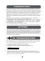
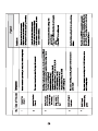
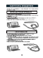
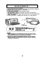
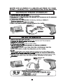
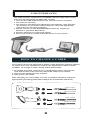
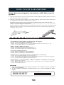
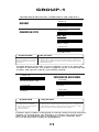
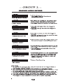
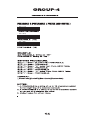
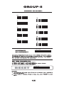
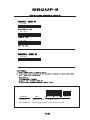
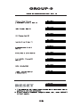
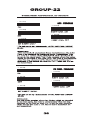
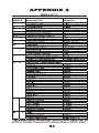
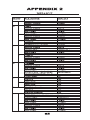
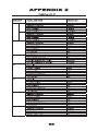
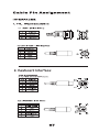
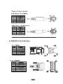
Ez One Shot
BAR CODE
SCANNER
USER'S
MANUAL
Default
DEFAULT
CHECK VERSION
Version: MAR20041021
CONTENTS
GENERAL
Table of contents
Introduction, Ez Troubleshooting
Cloning Mode
-------------------
1
2-3
4-5
Getting Started
How to fix the scanner to the terminal
How to change a cable
How to set up th e parameter
-------------------
6-9
9
10
SETTING GROUP
1
2
3
4
5
6
7
8~9
10
11
12
13
14
Interfaces selection, Computer type, Default
Reading Mode
Check Version, Beep tone, Caplock Mode
Preamble and postamble
Accuracy adjustment
Enable and Disable Code ID
Symbologies Code Identifier,
Set Code ID, Customer Configuration
Delay between block and character
Terminator & keyboard layout
RS232: Baud rate, Data bits & parity
RS232: Stop bit, handshaking, ACK/NAK,
Flow Control
Wand Emulation parameter setting
------11
------12
------13
------14
------15
------16
17
------------- 18-19
------20
--- ---21
------22
23
-------------
24
SYMBOLOGY FORMATTING ( GROUP 15~31)
15
16
17
18
19
20
21
22
23
24
25
26
27
28
29
30
31
Enable Barcode Symbology
Disable Barcode Symbology
China post code ( Toshiba code), Code 32
UK Plessy code, MSI code
Code IATA, Code93, Telepen
Interleaved 2 of 5, Code 11
Codabar
ABC Codabar, CX Codabar,
Codabar Coupling
Code 128, Standard Code 39, Full ASCII code
39
Industrial 2 of 5, Matrix 2 of 5
UPC-E
UPC-E(0) &(1), UPC-E & UPC-A Expand
UPC-A
EAN-8
EAN-13
EAN/UCC 128, ISSN, ISBN
-------------------------------------------------------------
26
27
28
30
32
34
36
38
39
40
-------------------------------------------
42
44
45
46
47
48
49
FULL ASCII (CODE 39 ) TABLE,
FUNCTION CODE TABLE
32~39Full ASCII table ( Code 39)
40
Numeric table
41~42Function code table (Code 39) for PC- AT
43~46Trouble Shooting
------- 50-57
------58
------- 59-60
------- 61-63
APPENDIX- A
Default
Cable pinout
------- 64-66
------- 67-68
INTRODUCTION
This scanner apply with Ez one shot easy programming decoder, It is
specially designed to deliver high-end bar code reading performance
at the lowest possible price. The scanner utilizes exceptional decoding
technology. One-time settings are easily made by scanning set-up bar
codes in this handy user's manual. This bar code scanner uses CCD or
optical diode technology which does not have moving part, provide
ragged reliable quality, enables it suit for any harsh environment
conditions. Furthermore, the LED illumination light source of scanner
provides less harmful beam to human eyes, and more longer product
lifetime.
The Ez One shot decoder are mainly apply to the following
categories bar code scanner for your reference:
1. Short Range- The reading distance is about from contact to 100mm,
2. Mid Range- The reading distance is about from contact to180mm,
3. Long Range - The reading distance is about from 5mm to 300mm,
4. Wand or Pen bar code scanner.
5. Scan Engine and Fixed Mount scanner .
Notes: ( Please contact your distributor for the detail model number.)
GENERAL
This scanner has many settings that can be used to conform the
unit to the requirements of a particular application. For most usages,
however,the default settings programmed into the unit at the factory
are appropriate.It is not recommended that the default settings be
changed unless thereis a specific need to alter the characteristics of
the scanner's performance.
EZ TROUBLESHOOTING
The scanner is easy to install and use. Many problems encountered
can be attributed to a wrong setting that has been programmed into
the scanner. Before troubleshooting the problem, try this:
1. Unplug the cable from the host computer.
2. Plug the cable back into the host computer.
3. Reset the scanner settings to DEFAULT (Group 1).
. A001$
If these steps do not resolve the problem, please refer to the
troubleshooting table on the next page. If this fails to correct the
problem, please consult the troubleshooting section beginning on
page 61~63 for further assistance.
2
CLONING MODE
WHAT IS CLONING MODE?
CLONING duplicates a wand's settings in other wands. It can save time
when a number of wands must be programmed to the same settings.
HOW SHOULD CLONING WORK?
1. Using this guide, make all the necessary settings for one wand.
2. Scan the CLONING MODE bar code shown below.
3. When CLONING MODE is scanned, all setup parameters will be
converted to alphanumeric characters and shown on the monitor.
4. Using a bar code printer, print out all the setup parameters as
Code 39 bar code labels.
5. Scan the printed labels sequentially with each wand to be
programmed.
. A016$
CLONING MODE
Figure 1
. A018$
CLONING MODE ON- PC/AT
.A018$( Cloning Mode on PC/AT) - you can clone the settings to a PC/AT
regardless what kind of device has been chosen on the scanner
NOTES:
1. All cloning strings are upper case.
2. All cloning strings printed on labels should be the same as those on
the monitor sequentially from first to last.
3. Cloning mode works in Word Note Pad only.
4. Never edit the data on the first row (.A017$). It is an entry gate for
cloning.
5. The cloning string's length can be adjusted by combining multiple
strings into one, or by breaking one string to multiple strings starting
from the second row after "....". Length must be in sequences of four,
such as 4,8,12,16,20 (MAX).
6. Be sure to print the dots exactly where they are shown on the monitor.
FORMAT OF CLONING
* Format of Cloning :
1st rows >>> ".A017$" ( never edit any data of the first row )
2nd rows >>> "....XXXX" you can adjust the String's Length starting
from the dots"...." forward. The length of the string should
be in 4, 8,12,16 or 20 ( MAX )digits.
3rd rows~ so on >>> XXXX
End rows- A dot "." Is an ending of cloning.
XXXX Stand for any String
4
USB INTERFACES
The USB Interface supported is compatible with the Apple MAC series,
later PCs and Windows 98, 2000, Me, and XP.
1. Connect the USB cable between the scanner and the computer.
2. The scanner will beep.
3. The Scanner will detect the USB driver automatically. (The first time
the scanner is connected via the USB port, follow the appropriate
instructions for the host computer.)
4. Set the scanner to KEYBOARD/USB interface by referring to
GROUP-1 (Interface Selections).
5. Scanner will beep to confirm the setting.
6. Scan a bar code to confirm that data shows on the monitor.
HOW TO CHANGE A CABLE
The CCD scanner are designed to switch easily between interface options.
To switch from one interface to another, the appropriate cable must be
installed. To change a cable, simply follow these steps:
1.To release the cable, insert a pin or straightened paper clip into the
hole at the base of the scanner where the cable is connected.
2. Remove the cable from the scanner.
3. Plug in the new cable.
After changing to a new cable, be sure to resetthe interface setting as
appropriate (including parameter settings for the RS-232 interface).
New Cable
Present cable
New Cable
Present cable
9
HOW TO SET PARAMETERS
How do you program a scanner with this user's
guide?
1. Use the scanner to scan at the bar code representing the function/
parameter you want to set.
2. When you hear two beeps, the new setting will have been defined
or updated into the memory processor.
Default parameters are indicated in bold type and underlined
characters. The character font is ARIAL BLACK. CD = Check Digit.
CDV = Check Digit Verification.
Most settings require only a single bar code, but a few need several
different bar codes to be scanned in order to completely define a
setting. They are:
SETTING BAR CODE
Preamble / Postamble (maximum 16 digits)
Step 1: Scan CLR PRE/POSTAMBLE.
Step 2: Scan PREAMBLE or POSTAMBLE..
Step 3: Scan any alphanumeric from Full ASCII Table in Groups 32 - 40.
Step 4: Scan PREAMBLE or POSTAMBLE.
Min Length / Max Length
Step 1: Scan MIN LENGTH or MAX LENGTH.
Step 2: Scan two digits from Appendix 1.
Step 3: Scan MIN LENGTH or MAX LENGTH .
Accuracy Adjustment
Step1: Scan ACCURACY ADJUSTMENT.
Step 2: Scan one digit from Appendix 1.
Step 3: Scan ACCURACY ADJUSTMENT.
Customer Configuration ID ( Example: Code 39 )
Step 1: Scan CODE 39 SET ID from Group 8.
Step 2: Scan either one digits or two digits alphanumeric (maximum 2 digits)
from Full ASCII table In Groups 32 - 40.
Step 3: Scan CODE 39 SET ID from Group 8.
Set A Data - ( CX-Codabar, ABC Codabar, Codabar Coupling).
Step1: Scan SET A DATA.
Step 2: Scan one digits any alphanumeric character from Full ASCII Table in
Groups 32 - 40.
Step 3: Scan SET A DATA.
NOTES:
1. The scanner will beep three times as a reminder that a setting is
not yet complete.
2. If you make a mistake, forget a step, etc., scan CLEAR to start
again.
.
RESET
. P 023$
10
GROUP-1
INTERFACES SELECTION, COMPUTER TYPE, DEFAULT.
. A001$
DEFAULT
. C004$
COMPUTER TYPE
PC- AT
. C006$
MAC ADB
. C007$
NOTEBOOK*
SYMPTOMS
SOLUTION
Scanner seems to be 1. Unplug the cable from the host computer.
performing as usual, 2. Plug the cable back into the host computer.
but no data is being 3. Set the scanner to the exact computer type
output.
immediately.
Caution:Please ensure the correct computer type is set when the
scanner is attached to a new host computer. If set to Notebook, the
scanner will operate with no external keyboard.
. C001$
INTERFACES SELECTION
. C008$
KEYBOARD& USB
. C003$
RS485
WAND
. C002$
RS232
SYMPTOM
The wand does not
scan/ The scanner
does not scan when
the trigger is
depressed.
SOLUTION
1. Unplug the cable from the host computer.
2. Plug the cable back into the host computer.
3. Set the wand to the correct interface. The
cable needs to match the interface.
Caution: This scanner is designed to switch easily between interface
options. To switch from one interface to another, the appropriate
cable must be installed. After changing to a new cable, be sure
to reset the interface setting as appropriate.
11
. A011$
. A012$
. A013$
0
5
1
6
2
7
3
8
4
9
. A010$
RESET
. P023$
. A008$
. A014$
. A015$
. A009$
145287
Preamble
145287
]E0
4 563987 123453
CODE ID
AIM ID : ]E0
12411
BARCODE / DATA
EAN 13 +5
OUTPUT : 145287]E0456398712345312411
GROUP-7
SYMBOLOGIES CODE ID IDENTIFIER, SET ID
SYMBOLOGIES CODE ID IDENTIFIER
SYMBOLOGIES
Factory
ID
AIM
ID
SYMBOLOGIES
Factory
ID
AIM
ID
. B001$
. B002$
. B003$
. B004$
. B005$
. B006$
. B010$
. B011$
. B012$
. B013$
. B014$
. C013$
. C010$
ENGLISH (USA)
. C014$
. C018$
ITALIAN
. C015$
. C011$
UNIVERSAL CODE
. C016$
. C012$
SWISS
FRENCH
. C017$
. C009$
JAPAN
. D013$
. D010$
CR+LF
. D014$
. D011$
TAB
. D015$
. D012$
. D016$
. E005$
. E001$
. E006$
. E002$
. E007$
. E003$
. E022$
. E004$
. E012$
. E008$
. E013$
. E009$
. E014$
. E010$
. E015$
. E011$
. E021$
. E016$
1 STOP BITS
. E017$
2 STOP BITS
. E018$
NONE
. E019$
CTS/RTS
. E020$
Xon/ Xoff
. E023$
ON
. E024$
. E025$
1 Sec
. E026$
3 Sec
. E027$
10 Sec
. E028$
. D001$
200us
. D002$
600uS
. D003$
LOW
. D004$
HIGH
. D005$
. D006$
Bar Low / Space High
. D007$
PEN TYPE
. D008$
FULL ASCII CODE 39
0
1
2
3
4
5
6
7
8
9
SETTING PROCEDURE
. P023$
0
1
2
3
4
5
6
7
8
9
SETTING PROCEDURE
. P023$
0
1
2
3
4
5
6
7
8
9
SETTING PROCEDURE
. P023$
. J001$
. J008$
. J002$
DISABLE
. J009$
. J003$
DISABLE CDV
. J014$
. J004$
CDV & SEND CD
. J005$
CDV & NOT SEND CDV
. J006$
MIN LENGTH ( 6 )
. J007$
MAX LENGTH ( 48 )
. I 010$
ENABLE
. I 043$
. I 011$
DISABLE
. I 012$
DISABLE CDV
. I 013$
CDV & SEND CD
. I 014$
CDV & NOT SEND CD
. I 015$
MIN LENGTH ( 6 )
. I 016$
. I 042$
MAX LENGTH ( 32 )
0
1
2
3
4
5
6
7
8
9
SETTING PROCEDURE
. P023$
0
1
2
3
4
5
6
7
8
9
SETTING PROCEDURE
. P023$
. I 017$
. I 039$
. I 018$
. I 036$
. I 035$
. I 022$
. I 040$
. I 023$
. I 038$
. I 037$
. I 019$
. I 041$
. I 020$
OFF
. I 026$
. I 021$
SET INSERT DATA*
. I 033$
. I 034$
ON
OFF
0
1
2
3
4
5
6
7
8
9
SETTING PROCEDURE
. P023$
0
1
2
3
4
5
6
7
8
9
SETTING PROCEDURE
. P023$
. H007$
. H010$
. H008$
. H011$
. H009$
. H012$
. H037$
ADD ON SUPPLEMENT
. H047$
. H038$
ADD A SPACE ON
. H048$
. H039$
ADD A SPACE OFF
. H055$
. H040$
ADDENDA REQUIRED OFF
. H056$
ADDENDA REQUIRED ON
. H0 6 4 $
. H0 6 3 $
. H0 6 5 $
E ( 1 ) ON
. H0 6 6 $
E ( 1 ) OFF
. H0 5 3 $
. H0 5 4 $
. H0 6 8 $
. H0 6 7 $
. H069$
. H070$
. H001$
ENABLE
. H004$
. H002$
DISABLE
. H003$
LEAD DIGIT SEND
. H005$
CHECK DIGIT SEND
. H006$
. H033$
+5 ON
. H034$
+ 5 OFF
. H035$
+2 ON
. H045$
ADD A SPACE ON
. H046$
ADD A SPACE OFF
. H059$
. H036$
ADDENDA REQUIRED OFF
+ 2 OFF
. H060$
ADDENDA REQUIRED ON
. H019$
. H0 2 2 $
ENABLE
. H020$
LEAD DIGIT NO SEND
. H0 2 3 $
DISABLE
. H021$
CHECK DIGIT SEND
. H024$
LEAD DIGIT SEND
CHECK DIGIT NO SEND
. H029$
. H043$
+ 5 ON
ADD A SPACE ON
. H030$
. H044$
+ 5 OFF
ADD A SPACE OFF
. H031$
. H061$
+ 2 ON
. H032$
ADDENDA REQUIRED OFF
. H062$
+ 2 OFF
ADDENDA REQUIRED ON
47
. H013$
ENABLE
. H016$
. H014$
DISABLE
. H015$
LEAD DIGIT SEND
. H017$
CHECK DIGIT SEND
. H018$
CHECK DIGIT NO SEND
. H025$
. H041$
. H026$
+ 5 OFF
. H042$
. H027$
+ 2 ON
. H057$
. H028$
+ 2 OFF
. H058$
ADDENDA REQUIRED ON
. M001$
. M005$
. M002$
. M006$
. M003$
. M007$
. M004$
. H049$
. H050$
. H051$
. H052$
GROUP-40
FULL ASCII NUMERIC TABLE ( CODE 39 )
0
1
2
3
4
5
6
7
8
9
58
GROUP-42
FUNCTION CODE TABLE ( CODE 39 )
$T O
Right
$T P
Left
$T Q
Up
$T R
$T S
Down
Page Up
$T U
$T T
Page Down
Tab
$T V
$T W
Back Tab
Esc
$T X
$T Y
Enter
BS
$T Z
Ins
$T %K
Del
Rs232 INTERFACE PROBLEMS