1
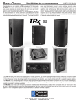
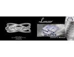
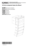
FPD 900.6 : SIX CHANNEL AMPLIFIER
Operation / Configuration
POWER PER CHANNEL:
•
6 X 150W into 4 ohms at less than 1% THD
•
4 X 200W + 2 X 275W into 2 ohms
•
Channels 5+6, 2 X 275W into 1 ohm
•
Bridged 4 Ohms - 2 x 400W + 1 x 500W
•
Bridged 2 Ohms - Channels 1+2, 3+4 NO. Channels 5+6, 1 x 500W
INPUTS SWITCH
•
2 = Use input 1+2 and route them to channels 3+4 and 5+6
•
4 = Use input 1+2 and 3+4
1+2 and 3+4 are attenuated by -6dB and routed to 5+6.
This allows constant bass loudness when you fade between 1+2 and 3+4.
•
6 = Use all six inputs.
CHANNELS 1 & 2 CROSSOVER CONFIGURATION
•
Flat: Full Range Signal. No crossover activated.
•
HP: Activates the High Pass Filter for a midbass or tweeter.
•
Copy 3 & 4: Copies the signals and filters from channels 3 & 4 to channels 1 & 2. Use this mode when you need
a band pass filter on all four channels. Recommended when bridging channels 1, 2, 3, 4.
CHANNELS 3 & 4 CROSSOVER CONFIGURATION
•
Flat: Full Range Signal. No crossover activated.
•
HP: Activates the High Pass filter.
•
LP/BP: Activates the selection of either a Low Pass filter for woofer or a Band Pass filter for midrange.
CHANNELS 5 & 6 CROSSOVER CONFIGURATION
•
Flat: Full Range Signal. No crossover activated.
•
HP: Activates the High Pass filter.
•
LP/BP: Activates the selection of either a Low Pass filter for woofer or a Band Pass filter for midrange.
•
Sub Mode: Inputs 5+6 are mixed to mono for bridge mono operation. Crossover slopes become 24dB.
The subwoofer remote volume control is activated. There is a clip distortion light on the remote volume control.
If you see this light is on, reduce volume until the light goes out so that you do not damage your speaker.
1
AUTOMATIC POWER TURN ON/OFF
1.
2.
The best way to automatically turn the amplifier power on and off is to use the REM wire from your source radio
connected to the REM amplifier terminal.
If your original equipment stereo or source radio has a BTL amplifier then the RCA inputs have an auto turn
on sensing circuit. When you connect the high level BTL speaker wires to the RCA input the REM wire is not
necessary.
RCA INPUT, BOTH LOW LEVEL AND HIGH LEVEL.
•
The amplifier LEVEL control has sufficient adjustment range for both low level and high level input into the RCA
jacks. A factory source radio that does not have RCA output, using the wires that are connected to the speakers,
can be directly connected to the RCA jacks when the amplifier LEVEL control is adjusted to 8V.
SETTING LEVEL
•
Set the amplifier LEVEL control to minimum before you turn on the amplifier for the first time.
•
For lowest distortion and lowest noise the amplifier LEVEL should be set at the lowest setting that yields
sufficient loudness without distortion. For lowest noise your source radio volume control should be near
maximum that does not cause distortion.
•
To find the best amplifier LEVEL setting:
With the amplifier LEVEL at minimum, slowly increase the source radio volume to around 3/4 without distortion.
Then, slowly turn up the amplifier LEVEL control to the maximum desired loudness. Listen very carefully and
turn down the amplifier LEVEL control if you hear any distortion.
SETTING SUBWOOFER HIGH PASS SUBSONIC FILTER
•
A subwoofer should have a high pass filter often called a subsonic filter. The purpose of a subsonic filter is to
limit very low frequencies that your subwoofer can not play loud enough without damage. Removing subsonic
frequencies can allow your subwoofer to play louder.
•
For a sealed box, the high pass is typically set between 10Hz and 30Hz to increase power handling capacity.
•
For a vented box, the high pass filter must be set 5Hz lower than the port tune frequency to prevent woofer
damage.
FPD 900.6 CONFIGURATION EXAMPLES
6 CHANNEL STEREO NON-BRIDGED
•
If you have two input wires from the source deck plug them into inputs 1+2.
Set INPUT switch to 2.
•
If you have four input wires from the source deck plug them into inputs 1+2 and 3+4.
Set INPUT switch to 4.
•
If you have five input wires from the source deck plug them into inputs 1+2 and 3+4. The subwoofer plugs into
channel 5. Set channel 5+6 MODE switch to SUB.
Set INPUT switch to 6.
•
If you have six input wires from the source deck plug them into inputs 1+2, 3+4, 5+6.
Set INPUT switch to 6.
2
•
If you are NOT using a subwoofer set all switches to flat. If you hear distortion in your woofers set all switch to
HP and adjust all HP frequency until the distortion goes away. This will probably be around 50 Hz to 70 Hz.
C1
6
RADIO
1
3
5
2
50Hz
4
COPY 3+4
6
FLAT
HP
BP
1K3
LP/BP
LP
100
70
93
13
10
1K3
HP
HP
120
4K
50
8v
1K
8v
LP
50Hz
+
+
XOVER
BRIDGE
+
+
GND
+
REM
BATT
0.2v
SUB
CONTROL
CH 5+6
LEVEL
0.2v
XOVER
LEVEL
LP
MODE
680
45
HP
+
XOVER
BRIDGE
BRIDGE
CH 3+4
FLAT
450
65
XOVER
1K3
70
4K
50
LEVEL
BP
HP FLAT
XOVER
650
200
20
6
0.2v
8v
HPF
37
4
LP/BP
XOVER
240
110
650
70
4K
50
SUB
LP
240
110
650
70
INPUTS
FLAT or HP
CH 1+2
240
110
2
50Hz
FLAT or HP
CH 2
CH 1
CH 4
CH 3
CH 6
CH 5
FLAT or HP
<GRAPHIC of Source Radio to input channel 1+2, 3+4, 5+6 of amplifier. Woofer/Tweeter/Xover on channels 1+2, 3+4, 5+6>
•
If you are using two subwoofers:
Put your woofer/tweeters on channel 1+2, 3+4.
Set 1+2, 3+4 switch to HP.
Adjust 1+2, 3+4 HP frequency to 50 Hz.
•
Subwoofers on channel 5+6.
Set channel 5+6 switch to LP/BP.
Set channel 5+6 MODE switch to SUB.
Plug in the remote sub control.
Adjust the 5+6 LP frequency to 50 Hz.
For a sealed box adjust the 5+6 HP frequency to 10 Hz.
For a vented box adjust the 5+6 HP frequency 5 Hz lower than the port tune frequency.
C2
SUBWOOFER
+
–
SUBWOOFER
6
RADIO
1
3
5
2
50Hz
4
COPY 3+4
6
FLAT
HP
BP
1K3
BP
4
6
1K3
HP
HP
4K
50
MODE
100
70
93
LP
120
20Hz
680
45
HP
SUB
1K
50Hz
8v
LP
0.2v
BRIDGE
BRIDGE
CH 3+4
+
XOVER
+
+
BRIDGE
+
+
+
+
–
GND
REM
BATT
8v
0.2v
LEVEL
SUB
CONTROL
FLAT
450
65
XOVER
1K3
70
4K
50
LEVEL
LP/BP
LP
HP FLAT
XOVER
650
200
13
10
0.2v
8v
HPF
37
20
LP/BP
XOVER
240
110
650
70
4K
50
SUB
LP
240
110
650
70
INPUTS
HP
CH 1+2
240
110
2
50Hz
HP
CH 5+6
LEVEL
CH 1
CH 2
CH 3
CH 4
CH 5
CH 6
REMOTE SUB CONTROL
LP/BP
C2 <GRAPHIC of Source Radio to input channel 1+2, 3+4, 5 of amplifier. Woofer/Tweeter/Xover on channels 1+2, 3+4, one
subwoofer wired to channel 5 one subwoofer wired to channel 6>
3
5 CHANNEL WITH BRIDGED SUBWOOFER
•
If you have two input wires from the source deck plug them into inputs 1+2.
Set INPUT switch to 2.
•
If you have four input wires from the source deck plug them into inputs 1+2 and 3+4.
Set INPUT switch to 4.
•
If you have five input wires from the source deck plug them into inputs 1+2 and 3+4. The subwoofer plugs into
channel 5. Set channel 5+6 MODE switch to SUB.
Set INPUT switch to 6.
•
If you have six input wires from the source deck plug them into inputs 1+2, 3+4, 5+6.
Set INPUT switch to 6.
•
Put your woofer/tweeters on channel 1+2, 3+4.
Set 1+2, 3+4 switch to HP.
Adjust 1+2, 3+4 HP frequency to 50 Hz.
•
One subwoofer bridged mono is wired to channel 5+ and channel 6-.
Set channel 5+6 switch to LP/BP.
Set channel 5+6 MODE switch to SUB.
Plug in the remote sub control.
Adjust the 5+6 LP frequency to 50 Hz.
For a sealed box adjust the 5+6 HP frequency to 10 Hz.
For a vented box adjust the 5+6 HP frequency 5 Hz lower than the port tune frequency.
C3
SUBWOOFER
+
6
RADIO
1
3
5
50Hz
4
2
6
COPY 3+4
FLAT
HP
BP
BP
4
6
1K3
HP
HP FLAT
HP
4K
LP
8v
120
20Hz
680
45
HP
SUB
1K
50Hz
8v
LP
0.2v
+
+
BRIDGE
+
+
+
GND
REM
BATT
0.2v
LEVEL
SUB
CONTROL
FLAT
450
65
+
XOVER
BRIDGE
BRIDGE
CH 3+4
200
93
XOVER
1K3
50
MODE
XOVER
650
70
4K
50
LEVEL
LP/BP
LP
100
70
13
10
0.2v
8v
HPF
37
20
LP/BP
XOVER
240
110
650
70
4K
50
SUB
LP
240
110
650
1K3
INPUTS
HP
CH 1+2
240
110
70
2
50Hz
HP
–
CH 5+6
LEVEL
CH 1
CH 2
CH 3
CH 4
CH 5
CH 6
REMOTE SUB CONTROL
LP/BP
C3 <GRAPHIC of Source Radio to input channel 1+2, 3+4, 5 of amplifier. Woofer/Tweeter/Xover on channels 1+2, 3+4, one
subwoofer wired to channel 5+ and channel 6->
TRIAMP A SUBWOOFER, WOOFER, AND TWEETER:
•
Connect the source deck front channel wires into inputs 1+2.
Set INPUTS switch to 1+2.
•
Connect your tweeters to channels 1+2.
Set 1+2 switch to HP.
Adjust 1+2 HP frequency to the tweeter manufactures recommendation. 3500 Hz is a good starting point.
•
Connect your woofers to channels 3+4.
4
Set channel 3+4 switch to LP/BP.
Set channel 3+4 switch to BP.
Adjust the 3+4 LP frequency to the manufactures recommendation. 3500 Hz is a good starting point.
Adjust 3+4 HP frequency to 50 Hz.
•
If you have two subwoofers connect one to channel 5 and one to channel 6.
•
If you have one subwoofer connect it to channel 5+ and channel 6-.
•
Set channel 5+6 switch to LP/BP.
Set channel 5+6 MODE switch to SUB.
Plug in the remote sub control.
Adjust the 5+6 LP frequency to 50 Hz.
For a sealed box adjust the 5+6 HP frequency to 10 Hz.
For a vented box adjust the 5+6 HP frequency 5 Hz lower than the port tune frequency.
C4
SUBWOOFER
+
WOOFER
–
TWEETER
RADIO
1
2
3
5
2
3.5K
4
COPY 3+4
6
FLAT
HP
BP
1K3
BP
4
6
1K3
HP
HP
4K
50
MODE
100
70
93
LP
120
20Hz
680
45
HP
SUB
1K
8v
LP
50Hz
+
0.2v
+
+
BRIDGE
+
+
+
GND
REM
BATT
8v
0.2v
LEVEL
SUB
CONTROL
FLAT
450
65
BRIDGE
BRIDGE
CH 3+4
–
1K3
70
4K
50
LEVEL
LP/BP
LP
HP FLAT
+
650
200
13
10
0.2v
8v
HPF
37
20
LP/BP
TWEETER
240
110
SUBWOOFER
WOOFER
LP/BP
LP
650
70
4K
50
SUB
3.5K
240
110
650
70
INPUTS
BP
CH 1+2
240
110
2
50Hz
HP
CH 5+6
LEVEL
CH 1
CH 2
CH 3
CH 4
CH 5
CH 6
REMOTE SUB CONTROL
LP/BP
C4 <GRAPHIC of Source Radio to input channel 1+2 of amplifier. Tweeter on channels 1+2. Woofer on channels 3+4. one
subwoofer wired to channel 5, one subwoofer wired to channel 6>
TROUBLESHOOTING:
> FOCAL SIGN DOES NOT LIGHT
1.
2.
3.
4.
5.
6.
7.
8.
Measure the voltage at the amplifier power terminal.
It should be between 12 and 15 volts.
Measure the voltage at the amplifier REM terminal.
It should be between 12 and 15 volts.
If you are using BTL high level for automatic turn on, try connecting a REM wire.
Check your power and ground connections to be correct polarity + and - and they are tight.
Check battery connections.
Check the fuse in the REM wire.
Check fuse at battery.
Check fuse inside amplifier.
The fuse is inside the right end cap beside the power terminals.
The recommended ATC fuse size is two 25 amp.
5
> FOCAL SIGN IS FLASHING
1.
2.
Is the amp very hot?
Wait a few minutes for it to cool down.
You need to get more fresh cool air to the amplifier.
Do not cover the amplifier or mount it flush into a hole.
If the amp is cold and the Focal sign is flashing, there is an internal fault. The amplifier must then be returned
for service.
> NO SOUND
1.
2.
3.
4.
5.
6.
7.
8.
9.
Is the Focal sign light off or flashing?
Is the source radio on and is there a sound signal coming from the source radio?
Use an ohm meter and measure the speaker wires for short circuit.
Check connections for small “wire whisker” that may be shorting between amplifier terminals or speaker
terminals.
Use an ohm meter and measure the speaker for short circuit.
Double check your connections to the source radio.
Are you using the correct source radio wires and are they plugged into the correct amplifier RCA?
Double check your connections to the speakers and speaker crossovers.
Check that all amplifier switches are in the correct positions for your speaker set up.
> AMPLIFIER BLOWS FUSE WHEN YOU TURN IT ON.
1.
Power and ground may be reversed.
Check + and - polarity at amplifier and at battery.
> SUBWOOFER REMOTE VOLUME CONTROL DOES NOT FUNCTION.
1.
2.
Check that Remote Volume Control wire is plugged into the amplifier securely.
The Remote Volume Control will not function if the amplifier switch is “DIRECT”. The switch must be in
“MASTER”.
> SUBWOOFER REMOTE VOLUME CONTROL LED LIGHT.
1.
2.
3.
While playing music the LED light should be Green.
Occasional red LED light flash indicates that the amplifier has reached maximum loudness.
If the red LED light flashes with the beat of the music,
TURN DOWN THE VOLUME before you damage your speaker.
If the red LED light is on continuous,
TURN DOWN THE VOLUME before you damage your speaker.
WARRANTY REGISTRATION CARD
6