1
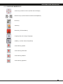
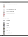
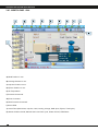
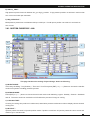
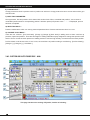
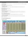
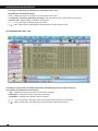
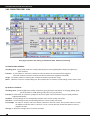
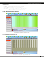
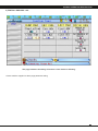
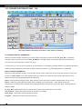
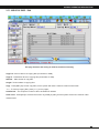
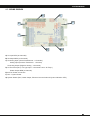
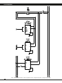
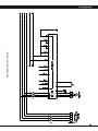
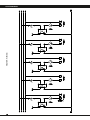
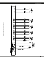
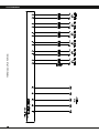
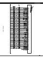
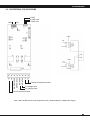
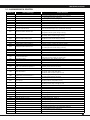
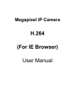
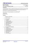
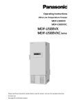
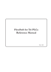
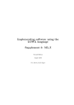
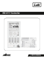
MH-6117 Controller AUTOMATION CORPORATION USER’S MANUAL CONTENTS CHAPTER 1 - SYSTEM SPECIFICATION 1.1 - Standard Conguration 05 1.2 - Hardware Conguration And Mounting Dimension 05 1.3 - Software Function 05 CHAPTER 2 - OPERATING PANEL DESCRIPTION 2.1 - Screen Selector 08 2.2 - Cursor And Numeric Key 09 2.3 - Operating Mode Selection 10 2.4 - Manual Operation Key 10 CHAPTER 3 - SCREEN OPERATION DESCRIPTION 3.01 - Wel Come Page 13 3.02 - Monitor Page 14 3.03 - Temperature Page 15 3.04 - Mold Open Close Page 16 3.05 - Injection Charge Page 17 3.06 - Ejector And Auto Purge Page 18 3.07 - Quality Record Page 19 3.08 - Production Page 22 3.09 - Core Page 24 3.10 - Carriage (Injection Unit) Page 26 3.11 - Mold File Page 27 CHAPTER 4 - SYSTEM WIRING 4.1 - Wiring Diagram 29 4.2 - Proportional (PQ) Card Wiring 39 CHAPTER 5 - TROUBLE SHOOTING 5.1 - Alarm Message And Solution 41 CHAPTER - 1 System Specification 1.1 - Standard Conguration 1.2 - Hardware Conguration And Mounting Dimension 1.3 - Software Function SYSTEM SPECIFICATION 1.1 - STANDARD CONFIGURATION Injection - Charge Page • MH6117 Control Module (PLC) • 3 Stage Injection Parameter • MH6117 Operating Controller (HMI Board) • 2 Stage Injection Hold Parameter • Proportional (PQ) Card • 2 Stage Charge Parameter • Emergency Push Button • 2 Stage Pre Suckback And Suckback Parameter • Ethernet Cable (Communication Cable) • Injection Mode Selection • Power Supply (Input 230Vac Output 5-15Vdc) • Suckback Mode Selection • Power Supply (Input 230Vac Output 24Vdc / 15Amp) • Injection - Charge Protection Timer • Cooling Time 1.2 - HARDWARE CONFIGURATION MH6117 Control Module (PLC) • Display unit CPU : ARM9 266 Mhz 32 bits • Control unit CPU : RISC 140 Mhz 32 bits • 6 Zone PID Temperature Sensor input • 5 Zone Heater Output (NPN) • 3 Linear Potentiometer Input (16bit) • 1 Analog Input (Pressure Transducer) Ejector - Air Ejector - Auto Lubrication Page • 2 Stage Ejector Advance Parameter • 2 Stage Ejector Retract Parameter • Ejector Mode Selection • Ejector Number • Air Ejector Parameter • Auto Lubrication Parameter • 3 Digital to Analog Output (16bit) • 32 Digital Input (NPN) • 32 Digital Output (NPN) Carriage - Auto Purge Page • 2 Stage Carriage Advance Parameter • 2 Stage Carriage Retract Parameter MH6117 Operating Controller (HMI Board) • Display unit CPU : ARM9 266 Mhz 32 bits • 7.4'' 800 X 400 TFT LCD Long Screen • LED Backlight • 1 USB Interface • Carriage Retract Selection • Carriage Retract Protection Time • Carriage Load Function • Auto Purge On/Off Selection • Auto Purge Number • Auto Purge Parameter 1.3 - SOFTWARE FUNCTION Temperature Page • 5 Zone Barrel Temperature Set • 1 Zone Oil Temperature Set • 5 Zone Barrel Temperature High-Low Tolerance Set • 1 Zone Oil Temperature High Tolerance Set • Nozzle Duty Function Mold Open Close Page • 5 Stage Mold Close Parameter • 5 Stage Mold Open Parameter • Low Pressure, High Pressure, Mold Open Protection Timer • Mold Adjustment Thick And Thin, Mold Open Close Parameter Core Page • 2 Core Parameter • Function + Timer Page Jump (Password Protect) Special Features • 3 Layer Password Protection • 120 Mold File Memory • Quality Record • Alarm Message • Modify Record • Input - Output Status • Production Record • Real - Time Display • Temperature Curve Graph 05 CHAPTER - 2 OPERATING PANEL DESCRIPTION 2.1 - Screen Selector 2.2 - Cursor And Numeric Key 2.3 - Operating Mode Selection 2.4 - Manual Operation Key OPERATING PANEL DESCRIPTION HMI OPERATING PANEL 07 OPERATING PANEL DESCRIPTION 2.1 - SCREEN SELECTOR Monitor Key (Actual Temperature, Actual Cycle Time, Actual Pressure & Flow) Temperature Key ( Set Temperature Parameter) Mold Key (Mold Open – Close And Mold Adjust Parameter) Injection Key (Injection Charge Parameter, Intrusion Page Selection) Ejector Key (Ejector, Air Ejector, Auto Lubrication Parameter) On-Off Key (Quality Record,Input – Output Status,Alarm Message,Modify Record) Production Key (Production Record) Core Key (Core Parameter, Fun + Timer Page Selection) Inject Curve Key ( Injection And Cusion Curve) Temperature Curve Key ( Temperature Curve) Carriage Key (Carriage Parameter, Auto Purge Parameter) Mold File Key (Mold File Save Parameter) 08 OPERATING PANEL DESCRIPTION 2.2 - CURSOR AND NUMERIC KEY Cursor Key (To Move Cursor Up-Down And Left-Right) Numeric Keys (To Enter Numeric Number And Alphabet) Enter Key Clear Key Reset Key (To Reset Alarm) Language Key (To Change Language) USB Key (To Take Screen SnapShoot) Cursor Moving upward Cursor Moving downward Cursor Moving leftward Cursor Moving rightward 09 OPERATING PANEL DESCRIPTION 2.3 - OPERATING MODE SELECTOR Manual Key (To Operate Machine In Manual Mode) Semi Auto Key (To Operate Machine In Semi Auto Mode) Auto Key (To Operate Machine In Auto Mode) Motor Key (To Start and Stop Motor) Mold Setup Key (To Adjust Die Height) Heater Key (To Start and Stop Heater) 2.4 - MANUAL OPERATION KEY Mold Close Key Mold Open Key Injection Key Charge Key Suckback Key Eject Adv. Key Eject Ret. Key Carriage (Unit) Adv. Key Carriage (Unit) Ret. Key 10 OPERATING PANEL DESCRIPTION Core 1 In Key Core 1 Out Key Core 2 In Key Core 2 Out Key Air Eject Key From Mold Moving Side Air Eject Key From Mold Fix Side Mold Thin Key Mold Thick Key Auto Mold Setup Key Auto Purge Key 11 CHAPTER - 3 SCREEN OPERATION DESCRIPTION 3.01 - Wel Come Page 3.02 - Monitor Page 3.03 - Temperature Page 3.04 - Mold Open Close Page 3.05 - Injection Charge Page 3.06 - Ejector And Auto Purge Page 3.07 - Quality And Input-Output Status Page 3.08 - Production Page 3.09 - Core Page 3.10 - Carriage (Injection Unit) Page 3.10 - Mold File Page SCREEN OPERATION DESCRIPTION 3.01 - WEL COME PAGE A) Left-down corner of initial page show the version of machine programs, Including MMI (Man Machine Interface program) • SYS(SYStem Program)• CAD(winCAD program) • PLC(PLC ladder program). B) After completing the system testing, the lower part will display the results to see if the system testing was normal or unusual. Moving on to press [ENT]key to enter < Machine Monitoring > page. Note : If system testing not complete than check communication cable or system power supply 13 SCREEN OPERATION DESCRIPTION 3.02 - MONITOR PAGE - 0100 A) Mold Position In mm. B) Carriage Position In mm. C) Injection Position In mm. D) Ejector Position In mm. E) Oil Temperature. F) Pressure Command. G) Flow Command. H) Back Pressure Command. I) Screw RPM. J) Actual Time.(Mold Close, Injection, Hold, Cooling, Charge, Mold Open, Ejector, Total Cycle). K) Status Of Motor On/Off, Manual Semi-Auto Auto Cycle, Heater On/Off, USB Detect. 14 SCREEN OPERATION DESCRIPTION 3.03 - TEMPERATURE PAGE - 0200 This page introduce the setting of temperature, details as following: A) TEMPERATURE SETTING SCREEN : This screen was designed to set those values related to each section of the barrel, which including: heating values upper-deviation lower-deviation . . . etc. If to press (CLR) button any section in “Heating Values” The setting value will display as ****, Which means this section only display the temperature which has been measured, not to be controlled. “UP-tol.” When the temperature of any section of the tube is higher than (setting value + UP-tolerance) high temperature deviation alarm will occur. “DN-tol.”:When the temperature of any section of the tube is lower than (setting value - DN-tolerance) Low temperature deviation alarm will occur. Note : When heating system switch on and the temperature of every section of the barrel higher/lower than (setting value - DN-tolerance + Up-tolerance) both high / low temperature deviation alarm will start to detect. B) NOZZLE DUTY FUNCTION : This is to set up the cycle time and duty percentage which nozzle is controlled under the same temperature status. 15 SCREEN OPERATION DESCRIPTION 3.04 - MOLD OPEN CLOSE PAGE - 0300 A B B D E F C This page introduce the setting of mold clamp, details as following: A) MOLD CLOSE PARAMETER : It provides data entry of pressure, speed and position, ve sections in total including : [Clamp 1] • [Clamp 2] • [Clamp 3] • [Low_P] • [High_P]. When the nal position of mold clamping setting during mold moving process to be 200.0 • 150.0 • 60.0 • 30.0 • 0.0 [Clamp 1] • [Clamp 2] • [Clamp 3] • [Low_P] • [High_P]. In other words, these values are set to be each section’s targeting position, above screen showed the map of related position in order: [Clamp 1 ≧ [Clamp 2] ≧ [Clamp 3] ≧ [Low_P] ≧ [High_P] B) MOLD OPEN PARAMETER : Mold Open also provides data key in columns which divided into ve sections from [Md_Op1] • [Md_Op2] • [Md_Op3] • [Md_Op4] • [Md_Op5], it also provides the corresponding pressure, speed, position setting to each section which is the same designed as Mold Clamp. In order to protect the mold and to increase the nal positioning accuracy of the mold opening, the end section of mold opening has a function which to force reducing the speed. Related position in order: [Md_Op1] ≦ [Md_Op2] ≦ [Md_Op3] ≦ [Md_Op4] ≦ [Md_Op5]. C) MANUAL MOLD ADJUSTMENT : To adjust pressure and ow of moving platen and die height platen in manual mode. D) LOW P_ PROT : Low pressure protect time work between clamp 3 to low_p position . If low pressure position not achieve in set time than error comes and mold open automatic. 16 SCREEN OPERATION DESCRIPTION E) HIGH P_ PROT : High pressure protect time work between low_p to high_p position . If high pressure position not achieve in set time than error comes and mold open automatic. F) MD_OPEN PROT : Mold pressure protect time work between Md op1 to Md op5 . If mold open-5 position not achieve in set time than error comes. 3.05 - INJECTION CHARGE PAGE - 0400 A F B C G D E H This page introduce the setting of Inject/Charge, details as following: A) INJECT MODE : Three ways including ” Pos (Position) ” Time and ” Pos+Time press (ENT) or ( ︽︾) Button to choose the transfer mode from injection to holding pressure process. B) SKBACK MODE : Press (ENT) or (︽︾ ) button to choose the suck back mode under bellowing 4 types : Standby • Presuck • Suckback and all . The screw would not suck back until it nishes the process of charge or cooling. C) COOLING TIME : Counting for cooling time products in molds need, stated after pressure maintenance. Above display column showed cooling time. D) INJ PROT : Injection protect time work in Injection position mode. If position not achieve in injection protect time error comes and machine go in manual mode. 17 SCREEN OPERATION DESCRIPTION E) CHARGE PROT : Charge protect time work in position mode. If position not achieve in charge protect time error comes and machine go in manual mode. F) INJECTION PARAMETER : Set up pressure, ow and position which shared with another timer. When controlled with position”, move cursor to unwanted injection section’s corresponding position” eld then press (CLR) button when “***”is displayed, procure has been completed. G) INJECTION HOLD : Pressure maintenance which can set up pressure/speed and time. Pressure maintenance time is 0.1 sec. H) CHARGE / SUCK BACK : There are four columns : [Pre Suck back] [Charge 1] [Charge 2] [Suck back] in adding each of them could set up pressure, speed and position. There are two stages in adding materials majorly designed to change the speed of each section and to control the back pressure of adding actions to achieve high density of material and accurate position. Pre Suck back could be set to be 0 if not in use, the restrictions of position setting is as following : [Pre Suck back] ≦ [Charge 1] ≦ [Charge 2] ≦ [ Suck Back ] 3.06 - EJECTOR AND AUTO PURGE PAGE - 0500 A F B C G D E H This page introduce the setting of Eject/Air, details as following: 18 SCREEN OPERATION DESCRIPTION A) EJECTOR MODE : Move the cursor to the column then press (ENT) or (︽︾) button to switch to “Standby” “Repeated” Oscillate” and “Holding” B) EJECT NUMBER : Setting the ejecting numbers of Repeated Mode C) SINGLE HOLD TIME : Setting the ejector waiting time for the action of robotic arm after ejection if choose the Holding ejecting mode. D) STATIC MOLD AIR : Enable the function of static mold blowing. E) MOVING MOLD AIR : Enable the function of moving mold blowing. F) EJECTOR PARAMETER : Pressure, ow and position of [EjAdv1] [EjAdv2] [EjRet1] [EjRet2]. The restrictions of position setting is [EjAdv1] ≦ [EjAdv2] [EjRet1] ≧ [EjRet2]. G) AUTO LUBRICATION PARAMETER : Enable the Function Of Auto lubrication. And Set up Count And Set up Time For Auto Lubrication On. H) AIR EJECT PARAMETER : Set up the start position, Pre delay time and Act time of [Mv Md Air] (Blowing from moving mold ) and [St Md Air] (Blowing from static mold ). 3.07 - QUALITY RECORD PAGE - 0600 A) QUALITY RECORD : 19 SCREEN OPERATION DESCRIPTION This Page Could Display The Quality Record Of Present 20 Cycles (500 Data Record Could Be Saved). 1) No. : Display the sequence number of recording data of each mold. 2) Cushion/Inj_Time/Chrg_End/Charg_Tm/Cycle_Tm : display the quality record values of each mold. 3) Record time : Display quality record time of each mold. 4) ︽︾ : To turn the page, each page shows 20 records. 5) : Under manual mode, press [ENT] key and password to delete all the records. B) ALARM RECORD PAGE - 0601 This Page Is To Record The Condition Before/after Alarm Message Occurred And To Provide The Operator Tracking Down The Problems. 1) No. : It displays the sequence number of each alarm message. 2) Messages : It displays the alarm number and messages. 3) Start/End:It displays the start and end time of alarms. 4) ︽︾ : To turn the pages, each page contains 20 records (totally saved up to 500 records) 5) 20 : Under manual mode, press [ENT] key and password to delete all the records. SCREEN OPERATION DESCRIPTION C) MODIFY RECORD PAGE - 0602 This Page Shows 20 Record of Forming Parameter Which Have Been Modied (Total 500 Could Be Saved). Serial Numbers, Mold Name, Accumulated Mode Numbers, Modifying Parts, Modifying Time, Old Values And New Values 1) No. : It displays the sequence number of each message. 2) Name of mold numbers : Name of modifying machine mold. 3) Accumulated mode numbers : Total mode numbers when modifying 4) Modifying parts : The name of the modifying parameters 5) Modifying time : Time when modifying. 6) Old values : Values before modifying 7) New values : To display new values 28 8) ︽︾ : To turn the pages, each page contains 20 records. 9) : Under manual mode, press [ENT] key and password to delete all the records. 21 SCREEN OPERATION DESCRIPTION 3.08 - PRODUCTION PAGE - 0700 A B This page introduce the setting of Production data, details as following: A) PRODUCTION SCREEN : Including parts : [Total] (Total production number) [Good] (Good numbers) [Bad] (Bad numbers) and [Box No.] (Box numbers). Function : It is the switch to control the numbers from above parts; that is the alarm will be triggered when the numbers have been achieved and the machine will be stopped automatically. Target :The setting values for achieving the correspond numbers of production target. Reset : Move the cursor the corresponding item, then press〔E NT〕 to reset the corresponding current value to zero. B) QUALITY CONTROL : Including parts : [Cushion] (Minimum position of injection) [Chrg_End] (the end position of charging) [MdOp_End] (the end position of mold opening) and [Cycle_Tm ] (Cycle Time). Function:It is the switch to control the quality from above four parts,when exceed the range of quality tolerance, judged as bad quality. QC Value : It is the settings for the corresponding absolute value of each quality control item. Tolerance : It is the settings for the corresponding tolerance of each quality control item. For example : QC value of ”Cushion” set to be 10.0mm, Tolerance” set to be 0.5mm, when present value is 11.2mm the difference with QC value is 1.2mm(11.2-10.0=1.2) and obviously exceed the tolerance 0.5 mm , judged to be bad. Average : It shows the average value of continue 30 molds. 22 SCREEN OPERATION DESCRIPTION OTHER SETTING : Cavity No. : It is the settings for the cavity numbers in one Mold. Cycle Delay : It Is the Settings for the auto cycle delay time. Cycle Tm Err. : It Is the setting for the cycle time error (total cycle time). If cycle not complete set cycle time than error occur. D) 24HR. PRODUCTION COUNTER PAGE - 0701 This page is to display 24hr. production data. E) 7 DAYS PRODUCTION COUNTER - 0703 This page is to display the 7 days production data. 23 SCREEN OPERATION DESCRIPTION 3.09 - CORE PAGE - 0800 C B A This page introduce the setting of core details as following. A) Core A : Type : Press the corresponding [ENT] or [︽︾] button to choose Core” or Screw” for a moving type. Func : Enable the corresponding function to work. Sensor : Choose limit switch for the position limitation of core or screw. When : Three choices when [A in] : Bf_MdCl ” [Before Mold Close] “ During ” (Mold Closing) and Af_MdCl” (After Mold Close); [A out] has three choices as well : Bf_MdOp ” (Before Mold Open) “During” (Mold Opening) Af_MdOp” (After Mold Open). Mold Pos. :If choose During”, it needs stop mold clamping and switch core to activate when the mold are at the position where we set. Time : When core type is Core and not choose position limitation switch this is set to be working time on the other hand is the protection time of activating. Teeth : When choose screw” type , correspond column can set up in/out numbers of screw pulses. B) Core B : The setting procedure is similar to Core A. 24 SCREEN OPERATION DESCRIPTION C) FUNCTION + TIMER PAGE - 0102 This page introduce the setting of function + timer details as following. Contact machine supplier for above page parameter setting. 25 SCREEN OPERATION DESCRIPTION 3.10 - CARRIAGE (INJECTION UNIT) PAGE - 1100 A B This page introduce the setting of function + timer details as following. A) CARRIAGE ADV-RET PARAMETER : Before to execute carriage movement, go to the left side of the page to switch ON the “AT_Carr_Ret.” (Automatic Carriage Return)” function and choose “Carr_Ret Mode” (Carriage Return control Mode, [Time] or [Position]) and ” Carr_Ret Prot”(Carriage Return Protection time). In this screen you can set up the pressure, ow and position of [CarAdv1] (Carriage Advance 1) [CarAdv2] [CarRet1] (CarRet1) and [CarRet2], the restrictions of position setting is [CarAdv1] ≧ [CarAdv2] [CarRet1] ≦ [CarRet2] B) AUTO PURGE PARAMETER : Before executing automatic purging, check if under manual control mode, then go to the left side of screen to open the function of “Auto_Purge”, key in the numbers of Purge number” then could enter the values of the pressure, ow, position and time of [Inj1] [Inj2] [Suckback] and [Charge]. Note 1:Under automatic purging motion, back pressure control will not be executed. (Whether been set up or not) Note 2 : Automatic purging process usually are as following: inject (Fast speed → slow speed), suck back (according to the position where operator set) charging(time which operator set); then inject again, repeat till fulll the setting numbers. AT_Carr_Ret : Enable the function of carriage return when running under semi or auto mode。 Carr_Ret Prot : Setting the protective time for the action of carriage. Auto_Purge : Select the function of purge movement. Purge No. :Setting the numbers of purge movement. 26 SCREEN OPERATION DESCRIPTION 3.11 - MOLD FILE PAGE - 1200 This page introduce the setting of mold le, details as following. Copy Fm: resource device of copying les (Controllers or USB). Copy To : Destination device of copying les (Controllers or USB). Start No. : Start number of copy les. Length : Total numbers of copying les. Copy : Press [ENT] key to start copy les, but the system will check if machine under manual mode. ︽︾ : To look up copying les, press [︽︾ ] to turn pages。 Load/Del No. : The sequence number of le to be loaded or deleted. Load or Del : Press [ENT] to execute the function of [LOAD] or [DEL], but the system will check if machine under manual mode. 27 CHAPTER - 4 System Wiring 4.1 - Wiring Diagram 4.2 - Proportional (PQ) Card Wiring SYSTEM WIRING 4.1 - WIRING DIAGRAM B F C E A G D A) X1-Input NPN (32 channels) B) X2-Output NPN (32 channels) C) X3-Analog Input (Linear Potentiometer - 3 channels) Analog Input (Pressure Transducer - 1 channel) X3-Analog Output (Digital to Analog - 3 channels) D) X4-Thermocouple (J or K type Input - 5 channels & 6 no. Oil Temp.) Heater Output NPN (5 channels) E) 24V DC Power Connection F) CN1 - System Power G) System Status (Run, Heater Output, Ethernet Communication & System Indication LED) 29 SYSTEM WIRING Note : Above 40 Ω Pressure / Flow proportional valve : Required 48V DC ~ 5Amp Power supply 30 ESS SERVO DRIVER WIRING SYSTEM WIRING 31 HEATER WIRING SYSTEM WIRING 32 ANALOG INPUT/OUTPUT WIRING SYSTEM WIRING 33 THERMOCOUPLE WIRING SYSTEM WIRING 34 SYSTEM PLC POWER SUPPLY WIRING SYSTEM WIRING 35 HMI DISPLAY WIRING SYSTEM WIRING 36 INPUT WIRING SYSTEM WIRING 37 OUTPUT WIRING SYSTEM WIRING 38 SYSTEM WIRING 4.3 - PROPORTIONAL (PQ) CARD WIRING GND V GND Q CMD input P CMD input +24v +39V Q1 Q Power Q+ QPower GND 15V 24V +24V P1 P Power P+ PPower GND P+ P- P POWER Q POWER P POWER GND Q POWER GND Q+ Q- Pressure Proportional Valve P1 Voltage input Q1 Voltage input Flow Proportional Valve Note : Above 40 Ω Pressure / Flow proportional valve : Required 48V DC ~ 5Amp Power supply 39 CHAPTER - 5 Troubleshooting 5.1 Alarm Message & Solution TROUBLESHOOTING 5.1 - ALARM MESSAGE & SOLUTION Alarm No. Alarm Message 008 Barrel Temperature too Low ! 019 Barrel Temperature too High ! Alarm Solution 1) Actual tempreture not achive the set tempreture 1) Actual tempreture is very high more than the set tempreture & up tolerance 1) Oil tempreture is very higher than the set tempreture 020 Oil Temperature too High ! 021 Injection Protection Time Error ! 1) Injection safety time is not set or low 022 Charge Protection Time Error ! 1) Charging safety time is not set or low 025 Mold Safty LS On Error ! 1) Mold safety Proxy/Limit switch input on 026 Mold Eject Bwd Plate Error ! 1) Ejector safety Proxy/Limit switch input on 030 Thermocouple Broken! 1) Thermocouple connection is wrong. 2) Thermocouple type (k or j) selection is wrong 031 Injection Position Sensor Err! 1) Injection linear scale selection is on 2) injection linear scale wiring is wrong 032 Clamp Position Sensor Err! 1) Clamp linear scale selection is on 2) Clamp linear scale wiring is wrong 033 Ejector Position Sensor Err! 1) Ejector linear scale selection is on 2) Ejector linear scale wiring is wrong 042 Reach Total Product Number! 1) Total product counter set value is achive 043 Reach Good Product Number! 1) Good Product counter set value is achive 044 Reach Bad Product Number! 1) Bad product counter set value is achive 049 Carriage Position Sensor Err! 1) Carriage linear scale selection is on 2) Carriage linear scale wiring is wrong 078 I/O Simulating ... 1) I/O is on from i/o simulation page 079 I/O Redirecting ... 1) I/O is change from i/o redirecting page 081 Core In Sequence Err! 1) Core in sequence selection wrong 082 Core out Sequence Err! 1) Core out sequence selection wrong 151 Communication Err ! 1) Plc and HMI ethernet cable is not connected proper 2)System Power Supply (5-15Vdc) Off 161 Emergency Stop! 1) Emergency stop button input is on 170 Oil Level too Low ! 1) Oil level input is on 172 Lubrication Oil Low 1) Lubrication Oil level input is on 176 Auto lubrication Fail ! 178 Mold Low Pressure Protection ! 180 Cycle Alarm 1) lubrication input is not come in set timer of auto lubrication 1) Mold low pressure protection time is not set or low 2) Mold close valve is not work 1) Cycle time is not set or low 183 Motor Overload ! 1) Motor amp. Is goes to high 2) Check motor star delta time 3) Motor delta comrm input X11 off. 185 High Pressure Protection Err ! 1) Mold high pressure protection time is not set or low 2) mold close valve is not work 186 Front Gate Protection Err ! 200 Servo Error ! 202 Servo Over Heat Err ! 1) 1) 2) 1) 2) Front gate input X1 is off Servo motor Alalrm X32 is off. Servo driver some alarm occur Servo motor temp. Input X7 is off Servo motor temp. Is high or Low 203 Motor isn't Running Or Started ! 1) Motor is off 206 Front Safety Gate Opened! 1) Front safety gate X1 is off 217 Unreach Normal Temperature ! 1) Actual tempreture is not achive the set tempreture 222 Screw Protection Err ! 1) Screw protection function is On. (Page.200) 223 Mold Open over Time ! 1) Mold open protetion time is set low.(Page.300) 224 Rear Gate Opened! 1) Rear gate input X2 is off 237 Carriage BWD Protect Err ! 1) Carriage protection time is not set or low 238 Mold Adj Thick L.S. On ! 1) Mold thick input X8 is on 239 Mold Adj Thin L.S. On ! 1) key lock input X9 is on 241 Key Down is Locked! 1) key lock input X28 is on 248 Eject Adv not in Position! 1) Ejector is not in position/Time is not over 249 Eject Ret not in Position! 261 Barrel Temperature too High ! 281 Mold Open is not in Position! 1) Ejector is not in position/Time is not over 1) Actual tempreture is very high more than the set tempreture & up tolerance 1) Mold open 5 position is not achive the actual mold Position. 287 Reach BOX Number ! 1) Total box counter value is achive or not set 41 PRODUCT RANGE MH-6117 MH-9118 FEATURES • Display unit CPU : ARM9 266MHz 32 bits • Control unit CPU : RISC 140MHz 32 bits • 7.4-inch 800 x 480 color TFT LCD long screen, LED back light • 6 Ranges PID temperature control (control accuracy ±1°C) • 3 Sets of transducer input (16 bit) • 1 Set of A/D pressure sensing input (16 bit) • 3 Sets of D/A proportional valve output (16 bit) • 32 Digital inputs • 32 Digital outputs • 1 USB interface FEATURES • Display unit CPU : ARM9 266MHz 32 bits • Control unit CPU : RISC 140MHz 32 bits • 8.4 inch 800 x 600 color TFT LCD • 8 Ranges of PID temperature control (control accuracy±1°C) • 4 Sets of transducer input (16 bit) • 2 Sets of A/D pressure sensing input (16 bit) • 4 Sets of D/A proportional valve output (16 bit) • 32 Digital inputs • 32 Digital outputs (expandable to 48/64 points) • 2 USB interfaces MH-9110 MQ- 200 FEATURES • Display unit CPU : ARM9 266MHz 32 bits • Control unit CPU : RISC 140MHz 32 bits • 10.4 inch 800 x 600 color TFT LCD • 8 Ranges of PID temperature control (control accuracy±1°C) • 4 Sets of transducer input (16 bit) • 2 Sets of A/D pressure sensing input (16 bit) • 4 Sets of D/A proportional valve output (16 bit) • 32 Digital inputs (expandable to 48/64 points) • 32 Digital outputs (expandable to 48/64 points) • 2 USB interfaces FEATURES • Display unit CPU : X86 800MHz 32 bits • Control unit CPU : RISC 140MHz 32 bits • 10.4 inch 600 x 800 16 bit color TFT LCD (Vertical) • 8 Ranges of PID temperature control (control accuracy±1°C) • 4 Sets of transducer input (16 bit) • 2 Sets of A/D pressure sensing input (16 bit) • 4 Sets of D/A proportional valve output (16 bit) • 32 Digital inputs (expandable to 48/64 points) • 32 Digital outputs (expandable to 48/64 points) • 2 USB interfaces LINEAR SCALE ROBOT PRESSURE TRANSDUCER Performance, Speed, Stability and Durability... All key attributes of robot make them ideally suitable for sprue separation and part removal on Injection Molding Machines. • Low maintenance, Higher stability and reliability due to lubricating pneumatic drive. • Fast responsive and reliable pneumatic control • High precision and low weight for injec on molding machinery 42 NOTE Sardar Patel Ring Road, Nr. Karai Gam Patia, Nana Chiloda, Dist. : Gandhinagar - 382 330. Lubi Electronics Tel. : +91-79-3984 5300 Fax : +91-79-3984 5599 E-mail : [email protected] Website : www.lubielectronics.com