1
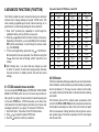
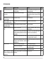
Table of Contents
6
7
8
9
Compass button ................................................................... 11
Display lighting ..................................................................... 11
Keypad lock.......................................................................... 11
Use of CALL button .............................................................12
Clock mode ..........................................................................12
5.11.a Setting the time .........................................................12
5.12 Chronometer mode ..............................................................12
ADVANCED FUNCTIONS (F BUTTON) .....................................13
6.1 CTCSS subaudio tone selection..........................................13
6.2 VOX mode ............................................................................13
6.2.a Activation/deactivation of VOX mode ....................... 14
6.2.b Setting VOX sensitivity ..............................................14
6.2.c Setting VOX delay .....................................................14
6.3 Scanning functions ..............................................................14
6.3.a Scanning on all channels ..........................................14
6.3.b Activating Dual Watch ...............................................15
6.4 Memory channels ................................................................15
6.4.a Programming of memory channels ...........................15
6.4.b Memory recall ............................................................15
6.4.c Memory scanning ......................................................16
6.5 Keypad tones, Calls and Roger Beep .................................16
6.5.a CALL function ...........................................................16
6.5.b Roger Beep ...............................................................16
6.5.c To enable/disable the keypad tones..........................16
CLEANING AND MAINTENANCE OF YOUR RADIO ...............17
7.1 Cleaning the radio ................................................................17
7.2 Connectors...........................................................................17
TROUBLESHOOTING ................................................................17
8.1 Reset of functions ................................................................17
8.2 Solution table .......................................................................18
TECHNICAL SPECIFICATIONS .................................................19
1
English
1 INTRODUCTION............................................................................2
2 ABOVE ALL… SAFETY! ..............................................................3
2.1 Symbols used ........................................................................3
2.2 Warnings ................................................................................3
2.2.a General ........................................................................3
2.2.b Batteries ......................................................................4
2.3 Assistance..............................................................................4
3 DESCRIPTION OF PARTS ...........................................................5
3.1 Description of parts and commands......................................5
3.2 Display symbols .....................................................................6
4 PREPARATION .............................................................................7
4.1 Fastening/removing the belt clip ............................................7
4.2 Installing/removing the batteries ...........................................7
4.2.a To install the batteries .................................................7
4.2.b To remove the batteries ...............................................8
4.3 Recharging the batteries .......................................................8
4.3.a Standard MW904 wall battery charger .......................8
4.3.b CA445 Intelligent, table-top battery charger ...............8
4.4 Proper use of rechargeable batteries ....................................9
4.4.a Memory effect..............................................................9
5 STANDARD FUNCTIONS ...........................................................10
5.1 Turning Alan 445 Sport on/off .............................................10
5.2 Volume regulation ................................................................10
5.3 Selecting a channel .............................................................10
5.4 Transmission and reception .................................................10
5.4.a Reception ..................................................................10
5.4.b Transmission .............................................................10
5.5 Monitor function ................................................................... 11
5.6 Selecting transmission power .............................................. 11
5.7
5.8
5.9
5.10
5.11
English
1 INTRODUCTION
ALAN 445 SPORT is a licence free PMR446 transceiver for use in
all existing EU countries (in Italy, PMR446 radios are subject to
general authorisation). Its use is also permitted in Turkey, Croatia,
Switzerland, Norway and Iceland.
The operating frequencies allow clear communications free from
atmospheric interference up to a distance of 4/5 km (under optimal
conditions: in open air and without any obstacles).
You can take your ALAN 445 SPORT everywhere and easily “wear” it
thanks to its included belt clip. It works with 4 AA type alkaline batteries
(or 4 Ni-CD / NiMH rechargeable batteries) and it can store up to 20
channels that can be quickly scanned (SCAN function).
To protect every channel from interference from other users, the ALAN
445 SPORT also has 38 CTCSS tones that guarantee impeccable
communications even over background noise amd interference.
ALAN 445 SPORT is also equipped with an electronic compass
and chronometer.
Main functions:
• 38 CTCSS tones in RX and TX
• Up to 20 channels stored
• Multifunctional backlit display
• Button for display backlight
• Auto power save: automatic current economy circuit reducing
the battery consumption by up to 50%.
• VOX / Babysitter function programmable in 6 different sensitivity
levels and 6 delays in reception levels.
• Roger Beep (end-transmission tone) on/off
• SCAN function with 2 types of scanning:
1. to monitor busy channels
2. to monitor the stored channels
2
•
•
•
•
•
•
Dual Watch (to scan 2 channels of your choice)
Keypad/switching on tone selectable on/off
Keypad lock/unlock
CALL button to send an acoustic signal to other users
UP/DOWN controls for the channel selection
MON (Monitor) to disable the automatic squelch
In our efforts to constantly improve product quality, we reserve the
right to change characteristics and features without prior notice.
2.1 Symbols used
For ease and convenience of use, this manual uses symbols to
highlight urgent situations, practical advice, and general information.
Symbols such as this one indicate a crucial description
regarding technical repairs, dangerous conditions, safety
warnings, advice, and/or other important information.
Ignoring these symbols may result in serious problems and/
or damage and/or personal injury.
Notes such as this one indicate practical advice that Midland suggests
be followed for the optimal performance of ALAN 445 SPORT.
Important sentences and words have been underlined.
2.2 Warnings
2.2.a General
Before using the transceiver, carefully read all the
instructions contained in this manual in the order in which
they are written. Cross-references to paragraphs and
chapters are provided for ease of use only. After reading,
keep this manual for future reference.
Read and follow all the warning and instruction labels found
on the radio and its accessories.
Always observe laws and regulations regarding the use of
transceivers, which may change according to the country
you are in. Where prohibited, or in areas where the radio may
cause interference or danger, turn off your radio.
Keep a tight grip on your radio (a fall may damage it) and
ensure the PTT button is not pressed accidentally when you
do not need to transmit. Do not hold the transceiver by the
antenna! This is a delicate part of the device and is vital for
the proper functioning of the radio.
Pay attention to environmental conditions - although Alan
445 Sport is designed to operate under the most severe
conditions, it is important to avoid exposure to environments
that are excessively humid or dusty, or to temperatures
outside the -15° to +55°C° range. Also avoid exposure to
direct sunlight, jarring, and excessive vibration.
Before using the radio, ensure that all protective covers are
in perfect operating condition, in order to ensure maximum
protection against humidity and atmospheric agents.
Although this radio was designed to be water resistant, avoid
getting it wet as much as possible and do not let any liquids
fall on it. If the transceiver or one of the accessories gets
wet, dry it off as soon as possible with a soft, clean cloth. If
you feel that liquid may have penetrated the radio’s housing,
contact a service centre for a diagnostic check.
Do not use the radio, its accessories, and/or substitute the
batteries in potentially explosive environments. A single
spark may cause an explosion.
Do not open the radio for any reason! Alan 445 Sport’s
precision mechanics and electronics require experience and
specialized equipment; for the same reason, the radio should
under no circumstances be realigned as it has already been
calibrated for maximum performance. Unauthorized opening
of the transceiver will void the warranty.
Use original accessories only; otherwise you may seriously
damage your handheld transceiver.
Turn off the radio before cleaning it. For further information,
refer to Chapter 7.
3
English
2 ABOVE ALL… SAFETY!
English
2.2.b Batteries
Before using the battery charger, carefully read all notes and
cautions regarding this equipment.
Do not short-circuit the battery terminals: doing so may
result in fire, burns, or explosions.
Never throw batteries into a fire or expose them to high
temperatures; doing so may cause fires or explosions.
Always follow the regulations set out by your country of
residence.
Use only the original batteries and battery charger. Use
of unapproved accessories may cause burns, fires, or
explosions, and may create serious damage to the radio/
batteries or to people.
The battery charger should only be used indoors.
Ensure your power supply conforms to the one required for
your battery charger (AC adaptor). If you are unsure, check
with your vendor or your local electricity supplier.
To avoid damaging the power cord to your battery charger,
connect it in a place where it will not be stepped on and
where nothing will be placed on top of it. Insert the prongs
into a socket that has been grounded.
Avoid shocks and excessive vibrations. Do not use the
battery charger if it has been subjected to strong shock,
had a fall, or if it appears damaged. Immediately contact an
authorized service centre.
Do not dismount the battery charger. Any repair work must
be performed exclusively by authorized service centers. For
further information, contact your local supplier.
To reduce the risk of electrical shocks, disconnect the power
cable before performing cleaning or maintenance. Grasp the
plug (not the cord!) when removing it from the socket. Use
4
of inappropriate extension cords may cause fire or electrical
shocks.
Do not expose the batteries directly to temperatures outside
the -20°C to +35°C range during storage and do not charge
them in temperatures outside the +5 to +55°C range.
2.3 Assistance
We advise you to write the serial number of your transceiver in the
space provided below. This number is found on the rear panel of the
transceiver and will be useful in the event of repair/assistance and/or
loss and/or theft.
Serial number............................................
3.1 Description of parts and commands
1
2
18
16
17
3
19
4
15
14
13
12
11
5
10
6
7
20
8
21
9
1. Antenna connector
2. ON/OFF/VOLUME knob - turns the equipment on/off and adjusts
audio volume.
3. LCD display - the LCD (liquid crystal) display constantly shows
the operating status of Alan 445 Sport and functions currently in
use.
4. SPK, MIC CHG sockets (on the radio’s side, under a protective
rubber flap) - perform the following functions:
• SPK and MIC CHG - jack sockets respectively for the speaker
and external microphone. Used together, these are used for
connection of optional accessories, such as microphones,
speakers, head/earphones, etc. Also, the MIC CHG socket
is used for connecting the (optional) standard MW904 wall
battery charger.
5.
button - confirms the selected setting.
6.
button - for scrolling downwards numerically through the tuned
channels and for setting functions.
7. Internal microphone - the transmission microphone is located
here.
8. Internal speaker - the speaker is located here.
9. Contacts for battery charging (bottom of the radio) - for
connecting the (optional) CA445 intelligent, table-top battery
charger.
10. button - for scrolling upwards numerically through the tuned
channels and for setting functions.
11. F (Function) button - for accessing the various programming
functions and settings of the radio.
12. button
(Monitor) - activates display backlighting, and
excludes (temporarily or permanently) the circuit which silences
the receiver in the absence of signals (squelch) so as to receive
signals that are extremely weak.
13. HI/LO
button–selects high or low transmission power and
activates/deactivates the keypad lock
14. CALL button - sends a two-tone audio call on your currently
selected channel.
15. STW (Stop Watch - Chronometer) button - recalls the
chronometer function.
16. PTT (Push To Talk) button - when pressed, this button sends
5
English
3 DESCRIPTION OF PARTS
the transceiver into transmission.
CLOCK button - activates the clock function.
Compass button - activates the compass feature
Belt clip fastener - for connecting the radio to the belt clip.
Cover of battery compartment - holds four AA batteries
(rechargeable 1.2V NiMH, or alkaline 1.5V) to supply your
handheld transceiver.
21. Clasp on battery compartment - holds the battery compartment
cover in place.
English
17.
18.
19.
20.
B)
C)
D)
E)
F)
3.2 Display symbols
Your transceiver is fitted with an LCD (liquid crystal) display to keep
you up to date on its operating status. The symbols and parameters
that appear are outlined below:
HB C D E J F
A
G
I
J)
K
O
L
G)
H)
I)
K)
L)
M)
N
M
N)
P
Q
O)
P)
A) Field strength indicator /relative transmission power during reception, this displays the strength of the signal received.
6
Q)
During transmission, it indicates the relative output power. The
level indicated is proportional to the number of bars seen.
Call - indicates that the two-tone audio call is activated.
Roger Beep - appears on the display when the Roger Beep
feature is activated
Keypad tones - indicates the activation of tones to confirm when
buttons are pressed.
Keypad lock - indicates that the keypad is locked.
Battery level - indicates the remaining battery power. The four
bars disappear proportionately as power decreases. When the
battery charge is no longer high enough to guarantee correct
functioning of the transceiver, this icon will flash to signal that the
batteries need to be recharged (or replaced).
LOW - indicates that low transmission power has been selected.
Compass
StopWatch (chronometer) - appears on the display when the
chronometer function is activated.
VOX - appears on the display when the VOX (Voice Operated
eXchange - hands-free transmission) function is activated.
DW - the transceiver is performing in Dual Watch mode.
Indicates whether the radio is in transmission or reception
mode.
These two large numbers indicate the channel currently selected.
During regulation of sensitivity or delay in VOX mode, they will
read as LE (level) or dL (delay).
These 4 small digits indicate different data, according to any
function selected, such as CTCSS tones, etc.
Mem - indicates that you are using one of the programmed
memories from your most-used channels.
Scan - appears when the transceiver is performing channel
scanning.
Power Saver - appears when the power saver is active.
Before using your transceiver, ensure that your package contains:
• The transceiver
• The belt clip
• The user’s manual (this manual)
If any part is missing or damaged, contact your supplier as soon as
possible.
In order for the device to function, you will require four AA batteries,
either 1.2V NiMH rechargeable or 1.5V non-rechargeable alkaline.
For further details, refer to par 4.2.
To charge the NiMH batteries without taking them out of the radio,
a standard MW904 wall charger is available, as well as a CA445
intelligent table-top charger. For further details, refer to par. 4.3
4.1 Fastening/removing the belt clip
The rear belt clip allows the user to easily clip the transceiver to a belt.
However, it may be necessary to remove the clip in order to facilitate
maintenance of the radio or battery changes. To fasten the clip to the
radio, position it above the groove found of the back of the transceiver,
then drag it downwards until it locks into place. To remove the clip
from the belt, lift the release lever and drag the clip upwards until it
comes free.
Ensure the belt clip is attached correctly ; otherwise the
transceiver may become unattached accidentally and fall.
4.2 Installing/removing the batteries
The transceiver operates with four AA batteries (not included). There
are two battery options available:
•
•
Rechargeable 1.2V NiMH - available in various capacities (in mA/
h). Higher battery capacity allows for greater duty, but requires
longer recharging time.
Non-rechargeable 1.5V alkaline.
For installing/removing the batteries, it is not necessary to remove
the belt clip (procedure outlined in par. 4.1), however, this does
make it easier to access the batteries.
Do not install a combination of rechargeable and alkaline
batteries in your transceiver. Always use 4 AA batteries of
the same type, brand, and from the same stock. Always use
the same batteries as a set in order to ensure their level of
charge is the same.
If you are not using the transceiver for an extended period,
remove the batteries.
4.2.a To install the batteries:
1. Unhook the clasp (A) downwards as indicated in picture 1.
2. Carefully lift the rear protective
cover from the battery compartment
and remove it.
3. Insert the batteries (rechargeable
or alkaline) in the battery
A
compartment, paying attention to
their polarity, as indicated on the
Pict. 1
inside of the battery compartment.
4. Carefully insert the cover’s tabs into the slots at the top of the
battery compartment, and then slowly press the cover down
against the battery compartment until it is aligned with the
transceiver body.
5. Carefully return the clasp (A) onto the protective cover, pressing
until it clicks into place.
7
English
4 PREPARATION
English
Ensure you have properly closed the battery compartment
cover.
4.2.b To remove the batteries:
1. Follow steps 1 and 2 as outlined above.
2. Remove the batteries from the radio.
3. Follow steps 4 and 5 as outlined above.
4.3 Recharging the batteries
Two types of battery chargers are available. Both allow you to charge
the NiMH batteries without removing them from the radio. They are:
• MW904: Standard wall battery charger - this is the least expensive.
It supplies a slow charge, allowing for maximum battery life. For
further details, refer to par. 4.3.a.
• CA445 intelligent table-top rapid charger - for rapid charging and
greater flexibility of use. It also monitors the charge, and once
batteries are charged, switches to trickle charging. For further
details, refer to par. 4.3.b.
New batteries do not immediately work at maximum capacity, as
they must be “run in” through at least 3 complete cycles of charge/
discharge.
Use the battery charger only if you have installed four
rechargeable NiMH batteries. Never attempt to charge other
types of batteries (particularly alkaline) - doing so may cause
explosions or injury.
Read the battery usage warnings outlined in par. 2.2.b
8
4.3.a Standard MW904 wall battery charger
1. Ensure the radio is turned off (it must remain off for the entire
period of charging).
2. Lift the rubber flap on the right side of the transceiver.
3. Insert the plug at the end of the MW904 battery charger cable into
the MIC CHG socket, then connect the battery charger to an AC
power source.
4. Once the batteries are charged (see table below for charging
times), disconnect the battery charger from the AC power source,
then disconnect the transceiver from the battery charger.
5. Return the rubber flap to its place.
TABLE OF APPROXIMATE TIMES FOR COMPLETE
RECHARGE, ACCORDING TO THE BATTERY TYPE USED.
Code
C696
C697
C734
Battery capacity
(mA/h)
1.200
1.700
2.300
Time (hours)
8
11.5
15.5
Do not overcharge the batteries! When the batteries are
completely charged, the charging process does not stop
automatically. Do not forget to disconnect the transceiver
from the battery charger as soon as possible after charging
is complete, otherwise you may seriously damage the
batteries and/or the transceiver.
For successive charging, longer duty, and battery life, refer
to par. 4.4.
4.4 Proper use of rechargeable batteries
When possible, recharge batteries only when at least two of the icon
bars have disappeared (the icon should indicate
). Be aware that
charging time will be shorter in proportion to the amount of residual
charge remaining in the battery, therefore, when only two bars appear
in the icon, this indicates you will require about 50% of time indicated
on the table in par. 4.3.a. This is particularly important if you use
the MW904 standard charger, otherwise you risk overcharging the
batteries.
If you use the batteries properly, you will obtain at least 400 cycles
of charge/discharge at maximum duty. It is normal for battery duty to
gradually decrease about 2/3 of the way into a battery’s life.
Rechargeable battery packs lose their charge over time even if
they are not used (auto-discharge); this is normal. A NiMH (Nickel
Metal Hydrate) battery may lose 10 - 20% of its energy within a
few days.
4.4.a Memory effect
Rechargeable NiMH (Nickel-Metal-Hydrate) batteries are virtually
unaffected by the “memory effect”. This phenomenon is associated
with a drastic reduction of battery autonomy and is triggered if the
batteries are regularly charged before having lost at least 50-75%
of their power and/or are not completely recharged. To avoid the
memory effect:
• When possible, recharge the batteries only when they are
completely discharged; i.e. when the battery indicator is
flashing.
• Do not disconnect the battery charger before the time indicated
for complete battery charging.
• Discharge and recharge your batteries completely at least twice a
month.
In any case, the best solution for avoiding the memory effect is to two
sets of batteries in turn: one in use, and the other being charged as
spare set.
The memory effect can be easily eliminated by completely charging/
discharging the batteries 3 or 4 times.
The memory effect should not be confused with the normal
battery life, which is (on average) 400 cycles of charge/discharge
. It is completely normal for operating duty to decrease when the
batteries have reached the end of their life; at this point, you will
need to change the battery set.
9
English
4.3.b CA445 Intelligent, table-top battery charger
This battery charger rapidly charge batteries and detects when
charging is complete.At this point it automatically switches to trickle
charge.
1. Insert the transceiver, with the charging contacts facing
downwards, into the CA445 battery charger slot, then connect the
battery charger to an AC power source. Charging will begin, and
an LED indicator will light up.
2. Once charging is complete, a green LED light will appear on the
battery charger, indicating the operation is complete and the
device has switched the trickle charge.
3. When possible and for increased security, remove the transceiver
from the charging slot and disconnect the battery charger from the
AC power source.
For successive charging, longer duty, and battery life, refer
to par. 4.4.
5 STANDARD FUNCTIONS
English
5.1 Turning Alan 445 Sport on/off
Turn the ON/OFF/VOLUME knob clockwise until it clicks on: the LCD
display will come on, and you will hear a beep (acoustic signal).
The LCD display backlight will automatically turn off after 10
seconds in order to save energy. The display will remain active.
To turn off the transceiver, turn the knob anti-clockwise until you
hear another click.
5.2 Volume regulation
Bring the ON/OFF/VOLUME knob to medium. Once the transceiver
receives a signal, adjust the volume to a comfortable level. If no
signal is received, use the
button as described in par. 5.5.
5.3 Selecting a channel
Press the or buttons respectively to scroll up or down through the
channels until you find the desired channel. To scroll quickly through
the channels, hold down the or button until you reach the desired
channel.
5.4 Transmission and reception
During transmission and reception, ensure the antenna is as
vertical as possible.
5.4.a Reception
When the PTT is not pressed, the radio is in reception and is ready to
receive incoming communications on the currently selected channel
10
(stand-by). If you are not receiving communications in stand-by and
have not activated any commands for at least 10 seconds, the display
will flash Power Saver, indicating that the power saver function has
been automatically activated. When ALAN 445 SPORT receives a
signal the following will happen:
•
•
The BUSY icon will appear on the display, along with the
icon, which indicates the strength of the incoming signal (the
number of bars being proportional to the strength of the signal).
The device which silences the audio in the absence of signals
(squelch) will automatically disable. If reception happens to be
broken, try to use the monitor function as described in par. 5.5.
5.4.b Transmission
1. To transmit, hold down the PTT (16) button: will appear on the
display, and the
icon will indicate your relative transmission
power (the number of bars is proportional to your relative
transmission power).
2. Then, at a distance of about 5cm, speak in a normal voice into the
transceiver’s microphone (7).
3. When you have completed your message, release the PTT button:
and
will disappear from the display and the transceiver will
return to reception mode.
You can only communicate with people that are tuned onto the
same channel.
If the BUSY icon appears on the display, but you don’t hear
anything, you may have accidentally turned the volume to the
minimum level.
The
(Monitor) button is for temporarily disabling the squelch
which reduces background noise thus enabling you to listen for
extremely weak signals. By doing this, you avoid listening to broken
communication.
To activate the monitor function, hold down the
button until you
hear background noise (or else a weak signal). Release the
button when you have finished listening.
If you wish to deactivate the squelch without holding down the
button, press the
button for at least 5 seconds, until you hear
two acoustic sounds (beeps), then release the button. The squelch
will remain disabled until you briefly press the
button again.
5.6 Selecting transmission power
To extend the battery duty, you can select low transmission power
when transmitting over short distances.
To do this, briefly press the HI/LO button: LOW will appear on
the display (low power is approx. 0.1 W). If you wish to transmit or
receive over long distances or with weak signals, press the HI/LO
button again: LOW will disappear and high power will be set (approx.
0.5W).
The transceiver is factory preset to transmit on high power.
2) “CAli br”
will be
displayed.
3) Rotate the radio fully twice
(360°), keeping it perfectly
parallel to the ground (as
indicated in picture 2).
4) Push the Compass button;
“Succes” will be displayed
if the calibration has been
Pict.2
successful or “FAil” in case
it has not been carried out.
We suggest you calibrate the compass each time the batteries are
removed from the battery compartment.
We suggest you calibrate the compass outdoors and in a place far
from magnetic sources.
5.8 Display lighting
Briefly press the
button. The backlight is activated for about 10
seconds. If you wish to deactivate it, press the
button again.
Display lighting uses additional battery energy. Try to use this
feature in moderation.
5.9 Keypad lock
5.7 Compass button
ALAN 445 SPORT is equipped with a precise electronic compass.
When you first switch on of the unit, the compass needs to be
‘calibrated’ as follows:
1) Turn on the radio and hold down the Compass button for at least
3 seconds.
To activate the keypad lock, hold down the HI/LO button until the
symbol appears on the display. This function deactivates all the
buttons on the front of the transceiver. Pressing one or more buttons
when in this mode will cause an audio signal of three consecutive
beeps. To deactivate the keypad lock, follow the description above
once again.
11
English
5.5 Monitor function
English
5.10 Use of CALL button
5.12 Chronometer/Stopwatch mode
The CALL button is used to make a call melody. Briefly press the
CALL button. The radio will go into transmission mode for approx.
ALAN 445 SPORT is equipped with a built-in stopwatch.
To activate it:
1. Press the STW (Stop Watch) button (15): StopWatch and 00: 00:00
will appear on the display.
2. To activate the chronometer, press the button. At this point, you
can:
• View the elapsed time, by pressing the button. To exit the
elapsed time viewing, press the button again.
• Stop the chronometer by pressing the button. To reactivate
the chronometer from its stopping point, press the
button
again. Or else press the
button if you wish to restart the
chronometer at 00: 00:00.
3. To exit the stopwatch function, press the STW button again.
When the stopwatch function is active, Alan 445 Sport is still
able to receive calls, but the display will continue showing the
chronometer’s progress.
When the stopwatch function is active, if you press the CALL or
PTT buttons, the radio will show the main screen during the call
but will continue to clock the chronometer’s progress, which will
appear on the display immediately afterwards.
two seconds, emitting a call. While this is happening, (transmission)
appear on the display, as well as the
indicator, showing your
relative transmission power.
5.11 Clock mode
This mode allows the user to see the current time on the LCD display.
To activate this, briefly press the CLOCK button.
5.11.a Setting the time
1. In clock mode, briefly press the
button. The hour will begin to
flash on the LCD display.
2. Press the or buttons to change the hour.
3. Briefly press the
button again. The minutes will begin to flash
on the LCD display.
4. Press the or buttons to change the minutes.
5. Briefly press the
button again to confirm the time.
6. To exit the clock mode, briefly press the CLOCK button.
When this mode is active, ALAN 445 SPORT will inform you
about a new incoming call, but the display will continue showing
the time. You can also transmit normally using the CALL or PTT
buttons. When this happens, the LCD display will automatically
switch to its regular operating screen, returning to clock mode as
soon as transmission is terminated.
12
The F button enables the user to access the transceiver’s advanced
functions and to change settings as required: CTCSS tones, VOX
mode, memory programming and recall, channel scanning, etc. In
general terms, to recall/change settings for various functions:
1. Press the F (Function) key repeatedly to scroll through the
available functions, until you find the one you want.
2. Press the o buttons to set the function currently on the screen.
Depending on the function, you can select On (function activated),
Off (function deactivated), or scroll through the various values
(e.g., from 01 to 06).
3. To store a changed setting, press either the
or the F button.
Both will perform the same operation, the difference being that
the
returns the radio to Standby, while F selects the next
function.
After following step 1, you must make any changes you wish
to within 10 seconds of each button being pressed, otherwise
the radio will return to standby and will store with the current
settings.
6.1 CTCSS subaudio tones selection
You can activate 38 CTCSS tones (CONTINUOUS TONE CODED
SQUELCH SYSTEM), which are a sort of access key and allow to
talk only with “your group” of users tuned on the same frequency and
on the same CTCSS tone. CTCSS tones allow you to share more
radio networks on the same frequency and allow you to receive only
messages coming from “your group”. To activate a CTCSS tone:
1. Push the F button. The number of the CTCSS tone blinks.
2. Press or to select the desired CTCSS tone.
3. Push the
button to confirm your selection.
If you don’t want a CTCSS tone, select 00.
NO
01
02
03
04
05
06
07
08
09
10
11
12
13
FREQ. (HZ)
67.0
71.9
74.4
77.0
79.7
82.5
85.4
88.5
91.5
94.8
97.4
100.0
103.5
NO
14
15
16
17
18
19
20
21
22
23
24
25
26
FREQ. (HZ)
107.2
110.9
114.8
118.8
123.0
127.3
131.8
136.5
141.3
146.2
151.4
156.7
162.2
NO
27
28
29
30
31
32
33
34
35
36
37
38
FREQ. (HZ)
167.9
173.8
179.9
186.2
192.8
203.5
210.7
218.1
225.7
233.6
241.8
250.3
6.2 VOX mode
VOX (Voice Operated eXchange) enables the user to activate handsfree transmission (without pressing any buttons) simply by speaking
into the microphone (7). This way, the user is able to rest the radio
on a nearby surface and still be able to communicate without picking
up the radio.
VOX functions best with the optional audio accessories which
connect to the SPK and MIC CHG jacks. By using these accessories,
the microphone will always be close to the user’s mouth, and apart
from the convenience of being hands-free, this will give the user an
even greater range of movement, especially with the radio clipped
onto the user’s belt.
13
English
6 ADVANCED FUNCTIONS (F BUTTON)
English
VOX is equipped with two settings (sensitivity and delay), which
allow for optimal use, as explained below.
If you use an external microphone, remember to replace
the rubberized protective flap on the radio after you have
finished using it.
6.2.a Activation/deactivation of VOX mode
1. Repeatedly press the F key until the VOX icon flashes. Below
this icon, the currently selected setting will appear (On = VOX
activated or Off = VOX deactivated).
2. Press the o buttons to change the VOX mode to On or Off.
3. Press the
button to confirm the setting change and return
to Stand-by, or press the F key to access the following menu
setting.
6.2.b Setting VOX sensitivity
Adjusting the VOX sensitivity avoids the likelihood of the radio going
into transmission mode because of environmental noise. As such,
it should be adjusted to the minimum level necessary to activate
transmission by voice.
1. Repeatedly press the F key until LE (sensitivity level) is displayed.
The VOX icon and the sensitivity level currently selected (from 01
to 06) will flash on the display.
2. Press the
o buttons to select the desired level (01 = most
sensitive, 06 = least sensitive).
3. Press the
button to confirm the setting change and return
to Stand-by, or press the F key to access the following menu
setting.
6.2.c Setting VOX delay
During transmission with VOX, a delay avoids the possibility that,
during short pauses in communication, the function does not return
14
the radio to reception mode. As such, this function should be set at
the minimum level necessary to guarantee optimum performance.
1. Repeatedly press the F key until dL (delay) appears. The VOX
icon and the delay currently selected (from 01 to 06) will flash on
the display.
2. Press the
o
buttons to select the desired delay time. Six
delay values are available, in increments of 0.5 seconds (01 = 0.5
seconds, 06 = 3.0 seconds).
3. Press the
button to confirm the setting change and return
to Stand-by, or press the F key to access the following menu
setting.
6.3 Scanning functions
6.3.a Scanning all channels
Alan 445 Sport can automatically search for signals throughout the
band by scanning, or selecting the channels in rapid sequence. When
a signal is detected, the scanning pauses on that channel and remains
blocked until the signal ends (for a maximum of ten seconds), giving
the user a chance to respond to a call, if necessary, before Alan 445
Sport automatically begins scanning again. To begin scanning, follow
the steps outlined below:
1. Repeatedly press the F key until the Scan icon and the currently
selected channel blinks on the display.
2. Press the o buttons to activate scanning. The transceiver will
begin to explore the band channels.
3. The transceiver will continue channel scanning until it picks up
a transmission. When this happens, the transceiver temporarily
halts scanning and remains tuned on that channel for about 10
seconds. During this time, you have the following options:
• If the communication does not interest you, wait for 10 seconds
6.3.b Activating Dual Watch
The Dual Watch function allows you to monitor two channels of your
choice at the same time by executing a scan on the two channels. To
select the Dual Watch function, follow the steps outlined below:
1. First, select a channel.
2. Repeatedly press the F key until the DW icon flashes on the
display.
3. Using the and buttons, select a second channel that you wish
to scan. After approx. one second, the transceiver will begin to
execute a scan on the two channels.
4. When the transceiver detects a transmission on one of the two
channels, Dual Watch temporarily pauses, remaining tuned for 5
seconds on the corresponding channel, giving the user a chance
to respond to a call. After this pause, the transceiver begins
scanning again.
5. If Dual Watch pauses on a channel on which you would like to
send a transmission, press the PTT button. This will deactivate
Dual Watch, allowing you to communicate normally. To reactivate
Dual Watch, follow the steps outlined above.
6. To exit Dual Watch mode and return to normal reception on the
currently selected channel, press the
button, or press the F
button to access the following menu setting.
6.4 Memory channels
The transceiver is equipped with 20 memories (from 01 to 20) into
which commonly-used channels can be saved. Once stored, these
channels can rapidly be recalled and scanned.
6.4.a Programming of memory channels
To store channels in the memories, follow the steps outlined below:
1. Repeatedly press the F key until the Mem icon flashes on the
display below the small memory number (from 01 to 20). The
channel currently selected will also begin to flash (large numbers).
Press the o buttons to select the memory number desired.
2. Press the F button again. Only the Mem icon and the band icons
will flash.
3. Press the o buttons to select the channel you want to store.
4. Push the F button again to select a CTCSS tone. The number of
this tone will blink on the display.
5. Press the o buttons to select the CTCSS tone you want to
store.
6. Press the
button to confirm your selection.
Now it is possible to:
• program another channel - by repeating steps 1 to 6.
• access the following menu setting –by pressing the F button
7. Push
to return to stand-by mode.
6.4.b Memory recall
To select a stored channel, follow the steps outlined below:
1. Repeatedly press the F key until the small memory number
(from 01 to 20) and corresponding stored channel appear on the
display.
2. The digit indicating the memory can either be fixed on the display
or can blink. In the former case, it means that the memory is
occupied by the channel displayed, in the latter case it means that
15
English
or press the o keys to begin channel scanning again.
If the communication is of interest to you, you can halt scanning
by briefly pressing the
or PTT buttons.
4. To exit the scanning mode and return to Stand-by on the currently
selected channel, press the
button, or press the F button to
access the following menu setting.
Scanning can only be executed on commonly-used channels . For
further details, refer to par. 6.4.c.
•
English
the memory is free.
3. To select the stored channel: press the o buttons and then the
PTT: Your radio will now operate on that channel.
6.4.c Memory scanning
To scan the stored channels only, follow the steps outlined below:
1. Repeatedly press the F key until the Mem and Scan icons are
flashing simultaneously on the display.
2. Press the o buttons to activate scanning. The transceiver will
begin scanning only the programmed memories.
3. The transceiver will continue scanning the programmed memories
until it picks up a transmission. When this happens, the transceiver
will temporarily halt scanning, remaining tuned on that memory
channel for about 5 seconds. During this period, you have a few
options:
• If the communication does not interest you, press the o
buttons to begin memory scanning again.
• If the communication is of interest to you, you can halt scanning
by briefly pressing the
button.
To exit the scanning mode and return to Stand-by on the currently
selected channel, press the
button, or press the F button to
access the following menu setting.
6.5 Keypad tones, Call and Roger Beep
Alan 445 Sport allows to use or disable the keypad tones and end
transmission tones (Roger Beep)
6.5.a CALL function
The CALL feature generates a call (4 two-tone audio sequences) on
the channel selected.
1. Press repeatedly the F key until the icon
flashes. Below, the
16
current setting blinks (VIbra =Vibration activated, RIng = tones
activated, V+r=Vibration + tones activated).
2. Push
or to select the desired modality.
3. Press
to confirm your selection and to return to the stand-by
mode. Alternatively, push the F button to access to the following
menu setting.
6.5.b Roger Beep
Every time the PTT is released, ALAN 445 SPORT will beep to
confirm the transmission has finished and that your partner may start
speaking.
1. Press the F button until the icon
blinks. Below, the current
setting flashes (On = tones activated or Off = tones disabled).
2. Push or to set the Roger Beep to On or Off.
3. Push
to confirm your selection and to return to the standby mode, or push the F button to access to the following menu
setting.
6.5.c To enable/disable the keypad tones
Keypad tones are emitted each time a button is pressed in order to
reduce the likelihood of accidentally pressing a button twice. This
function can be deactivated if you prefer the radio to be silent. To
activate or deactivate the keypad tones, refer to the steps outlined
below:
1. Repeatedly press the F key until the icon begins flashing. Below
this icon, the current setting will also flash (On = tones activated
or Off = tones deactivated).
2. Press the o buttons to change the keypad tone to On or Off.
3. Press the
button to confirm the setting change and return
to Stand-by, or press the F key to access the following menu
setting.
MAINTENANCE
OF
7.1 Cleaning the radio
Carefully rub the radio using a soft, clean cloth that does not have
loose fibers. If the radio is very dirty, slightly dampen the cloth with a
mixture of water and a neutral soap.
Do not use detergents, alcohol, solvents, or abrasives.
While cleaning the radio, always keep the rubber flap over
the side connectors, the antenna, and the battery well in
place. Do not under any circumstances allow the connectors
or electrical contacts to get wet.
7.2 Connectors
When the connectors are not being used, they must be covered with
their protective rubber flap.
Only use original accessories or those approved by CTE
International, otherwise you may damage the radio.
8 TROUBLESHOOTING
Your ALAN 445 SPORT is designed to provide you with years of
optimal performance. If for some reason a problem should arise we
suggest you consult this chapter before contacting your local service
centre.
8.1 Reset of functions
If your transceiver experiences a logical malfunction (improper
symbols on the display, blocking of functions, etc.), it may not be
experiencing a true failure, but rather a problem caused by external
factors. For example, it may have an incorrect setting brought on by a
noise or spikes in the electrical system during battery recharging. In
such cases, you can reset the transceiver to its factory-programmed
settings, deleting memories and resetting all functions. To do this:
1. Turn off the transceiver.
2. Hold down the F button, and at the same time, turn on the
transceiver; all of the icons and symbols will appear simultaneously
on the transceiver.
3. Release the F button. All settings will return to the factoryprogrammed ones. For example, the radio will be reset on the
channel 1, high transmission power will be selected, etc.
Before you reset the radio, we suggest you write down all of the
settings you have previously entered, as they will be cancelled
during the reset.
17
English
7 CLEANING AND
YOUR RADIO
8.2 Solution table
English
Problem
Alan 445 Sport does not turn on
Possible Cause
Solution
The batteries are not charged and/or are not Ensure the batteries are charged and correctly
correctly inserted
inserted in the radio
Alan 445 Sport turns off as soon as The batteries have lost their charge
If the batteries are alkaline (non-rechargeable),
it is turned on
substitute them; otherwise, charge your NiMH
batteries.
Alan 445 Sport turns on, but does The volume is too low
Adjust volume level
not receive signals
During
reception,
you
hear The monitor function was accidentally left Deactivate the monitor function
continual background noise
active
You are unsuccessful in establishing Incorrect selection of channel or local band
Check your channel
contact with your party
Reception is broken and/or with Signal is extremely weak
Temporarily deactivate squelch using the
noise
Monitor function
Your party is too far away and/or transceiver Move closer to your party and/or move the
antenna is shielded by obstacles in the direction transceiver to a less shielded area
of your party
Other users are using the same radio channel Check the radio traffic on the selected channel
and change channels if necessary
Alan 445 Sport is positioned too close to other Move Alan 445 Sport away from the interference
interference devices (televisions, computers, devices
transmitters, etc.)
Battery life is short
Excessive use of display backlighting
Use less display backlighting
Excessive use of transmission
Try to reduce transmission times and/or use
low transmission power
Memory effect is occurring with the batteries
Eliminate memory effect
Logical malfunction (improper Incorrect setting brought on by electrical Reset your radio
symbols on the display, blocking of disturbance
functions, etc.)
18
Ref
4.2
4.3
5.2
5.5
5.3
5.5
-
5.4.a
-
5.8
5.6
4.4.a
8.1
9 TECHNICAL SPECIFICATIONS
GENERAL
-
8
Sensitivity @ 12dB Sinad
µ
Better than 0.35 µV
Frequency generation
-
PLL synthesizer
dB
70
Standard frequencies
MHz
CH1:446.00625 Mhz
CH2:446.01875 Mhz
CH3:446.03125 Mhz
CH4:446.04375 Mhz
CH5:446.05625 Mhz
CH6:446.06875 Mhz
CH7:446.08125 Mhz
CH8:446.09375 Mhz
12.5 KHz
Adjacent channel
rejection
Audio output power (10%
THD)
Frequency response
mW
300
Hz
300 - 3000 Hz
Intermediate frequencies
MHz
1°: 21.7MHz - 2°: 0.450MHz
Squelch
-
Automatic
-
Jack stereo 2,5 mm
-
Jack mono 3,5 mm
Channel spacing
KHz
Power supply
Vdc
Operating temperature
°C
from 4,8 to 6 (4 AA NiMH
rechargeable or alkaline
batteries)
from -20° to +55°
Dimensions
mm
126x 55x38
Weight
g
157
Modulation
W
-
High power
Low power
FM
Spurious reduction
-
Within European legal terms
Deviation
KHz
±2.5 KHz (max)
English
RECEIVER
Channels
CONNECTIONS
Socket for ext mike and
recharge
Socket for external
speaker
TRANSMITTER
Output power (6 Vdc)
500mW
100mW
Frequency tolerance
±2.5PPM (-20°C / +55°C)
Current drain
< 450mA / 6V (dry cells)
Specifications are subject to modification without forewarning.
19
20
English