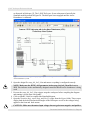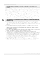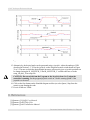
1
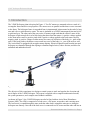
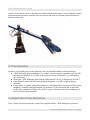
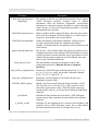
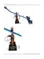
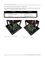
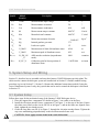
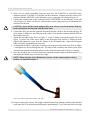
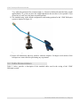
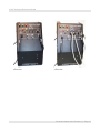
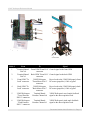
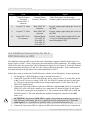
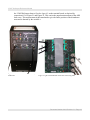
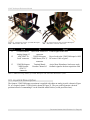
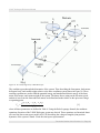
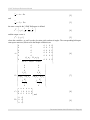
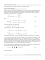
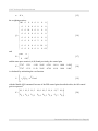
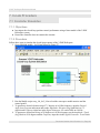
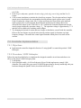
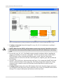
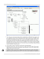
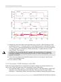
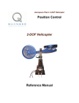
Aerospace Plant: 3-DOF Helicopter Position Control 3-DOF Helicopter Reference Manual 3-DOF Helicopter Reference Manual Table of Contents 1. INTRODUCTION..........................................................................................................................................1 2. PREREQUISITES..........................................................................................................................................2 3. EXPERIMENT FILES OVERVIEW..................................................................................................................2 4. SYSTEM DESCRIPTION................................................................................................................................4 4.1. Components......................................................................................................................................4 4.1.1. 3-DOF Helicopter Components..............................................................................................................4 4.1.2. Active Disturbance System Components................................................................................................7 4.2. System Specifications.......................................................................................................................8 4.2.1. 3-DOF Helicopter Parameters................................................................................................................8 4.2.2. ADS Parameters.....................................................................................................................................9 5. SYSTEM SETUP AND WIRING....................................................................................................................10 5.1. System Setup..................................................................................................................................10 5.2. Cable Nomenclature.......................................................................................................................12 5.3. Typical Connections For The 3-DOF Helicopter...........................................................................15 5.4. Additional Connections for the 3-DOF Helicopter w/ ADS..........................................................19 5.5. Joystick Description........................................................................................................................21 6. MODELING AND CONTROL DESIGN...........................................................................................................22 6.1. Modeling.........................................................................................................................................22 6.2. Control Design................................................................................................................................25 7. IN-LAB PROCEDURE................................................................................................................................27 7.1. Controller Simulation.....................................................................................................................27 Document Number 644 / Revision 2.1 / Page i 3-DOF Helicopter Reference Manual 7.1.1. Objectives.............................................................................................................................................27 7.1.2. Procedure.............................................................................................................................................27 7.2. Controller Implementation..............................................................................................................28 7.2.1. Objectives.............................................................................................................................................28 7.2.2. Procedure: 3-DOF Helicopter...............................................................................................................28 7.2.3. Procedure: 3-DOF Helicopter with ADS..............................................................................................32 8. REFERENCES...........................................................................................................................................35 Document Number 644 / Revision 2.1 / Page ii 3-DOF Helicopter Reference Manual 1. Introduction The 3-DOF Helicopter plant is depicted in Figure 1. Two DC motors are mounted at the two ends of a rectangular frame and drive two propellers. The motors axes are parallel and the thrust vector is normal to the frame. The helicopter frame is suspended from in instrumented joint mounted at the end of a long arm and is free to pitch about its centre. The arm is gimbaled on a 2-DOF instrumented joint and is free to pitch and yaw. The other end of the arm carries a counterweight such that the effective mass of the helicopter is light enough for it to be lifted using the thrust from the motors. A positive voltage applied to the front motor causes a positive pitch while a positive voltage applied to the back motor causes a negative pitch. A positive voltage to either motor also causes an elevation of the body (i.e., pitch of the arm). If the body pitches, the thrust vectors result in a travel of the body (i.e., yaw of the arm) as well. The vertical base is equipped with an eight-contact slipring. Electrical signals to and from the arm and helicopter are channeled through the slipring to eliminate tangled wires, reduce friction, and allow for unlimited and unhindered travel. Figure 1 3-DOF Helicopter when running. The objective of this experiment is to design a control system to track and regulate the elevation and travel angles of the 3-DOF Helicopter. The system is supplied with a complete mathematical model, the system parameters, and a sample state-feedback controller. As shown in Figure 2, the 3-DOF Helicopter can also be fitted with an Active Mass Disturbance System (ADS). The ADS is comprised of a lead-screw, a DC motor, an encoder, and a moving mass. The lead-screw is wound through the mass such that when lead is rotated the mass moves along the helicopter arm linearly. One end of the lead-screw is connected to a DC motor and the other end has an Document Number 644 / Revision 2.1 / Page 1 3-DOF Helicopter Reference Manual encoder. As the motor is driven, the lead-screw rotates and causes the mass to move. Using the encoder measurement and a position controller, the user can move the mass to a desired position and actively disturb the helicopter. Figure 2: Active Disturbance System on the 3-DOF Helicopter. 2. Prerequisites In order to successfully carry out this laboratory, the user should be familiar with the following: ● 3-DOF Helicopter main components (e.g. actuator, sensors), the data acquisition card (e.g. Q8), and the power amplifier (e.g. UPM), as described in Section 4, Reference [1], and Reference [4], respectively. ● Wiring the 3-DOF Helicopter plant with the UPM and DAC device, as discussed in Section 5. ● State-feedback control and the Linear-Quadratic Regulator, i.e. LQR, enough to design a controller. ● Using QuaRC, or another equivalent software, to control and monitor a plant in real-time and in designing a controller through Simulink. See Reference [2] for more detail and, in particular, ensure a few examples described in the Model Examples section are ran before running any of the 3-DOF Helicopter controllers. 3. Experiment Files Overview Table 1 below lists and describes the various files supplied with the 3-DOF Helicopter experiment. Document Number 644 / Revision 2.1 / Page 2 3-DOF Helicopter Reference Manual File Name Description 3-DOF Helicopter Reference Manual.pdf This manual is both the user and laboratory guide for the Quanser 3-DOF Helicopter specialty aerospace plant. It contains information about the hardware components, specifications, information to setup and configure the hardware, system modeling, control design, as well as the experimental procedure to simulate and implement the controller. 3-DOF Heli Equations.mws Maple worksheet used to analytically derive the state-space model involved in the experiment. Waterloo Maple 9, or a later release, is required to open, modify, and execute this file. 3-DOF Heli Equations.html HTML presentation of the Maple Worksheet. It allows users to view the content of the Maple file without having Maple 9 installed. No modifications to the equations can be performed when in this format. quanser.ind and quanser.lib The Quanser_Tools module defines the generic procedures used in Lagrangian mechanics and resulting in the determination of a given system's equations of motion and state-space representation. It also contains data processing routines to save the obtained state-space matrices into a Matlab-readable file. setup_lab_heli_3d.m setup_heli3d_configuration.m setup_ads_configuration.m HELI3D_ABCD_eqns.m s_heli3d.mdl q_heli3dr_zz.mdl The main Matlab script that sets the model, control, and configuration parameters. Run this file only to setup the laboratory. Returns the 3-DOF Helicopter model parameters Kf, m_h, m_w, m_f, m_b, Lh, La, Lw, and g, the encoder calibration constants K_EC_T, K_EC_P, and K_EC_E. Returns the various parameters associated with the Active Disturbance System (ADS). Matlab script file generated using the Maple worksheet 3-DOF Heli Equations.mws. It sets the A, B, C, and D matrices for the state-space representation of the 3-DOF Helicopter open-loop system which is used in s_heli3d.mdl and to design an LQR-based controller. Simulink file that simulates the closed-loop 3-DOF Helicopter system using its linear equations of motion model and a position controller. Simulink file that implements the real-time state-feedback LQR controller for the 3-DOF Helicopter system. The zz suffix denotes the data acquisition board used, for example the q4 or q8. Table 1: Files supplied with the 3-DOF Helicopter experiment. Document Number 644 / Revision 2.1 / Page 3 3-DOF Helicopter Reference Manual 4. System Description The following is a listing of the major hardware components used for this experiment: ● Power Amplifier: Two Quanser UPM-2405, or equivalent. ● Data Acquisition Board: Quanser Q3, Q4, Q8, or equivalent. ● Helicopter Plant: Quanser 3-DOF Helicopter aerospace experiment with or without the Active Disturbance System (ADS). ● Real-time control software: PC equipped with QuaRC-Simulink configuration. See the references listed in Section 8 for more information on these components. 4.1. Components Section 4.1.1 lists the components on the 3-DOF Helicopter plant and Section 4.1.2 describes the components on the 3-DOF Helicopter device with the Active Disturbance System (ADS). 4.1.1. 3-DOF Helicopter Components The components comprising the 3-DOF Helicopter system are labeled in figures 3, 4, and 5 are described in Table 2. The motors, propeller assemblies, and encoders are described in more detail below. ID # Description ID # Description 1 Helicopter body 11 Slip ring 2 Motor 12 Base 3 Front propeller assembly 13 Ball-bearing block 4 Back propeller assembly 14 Travel encoder 5 Pitch encoder 15 Front motor connector 6 Arm 16 Back motor connector 7 Elevation encoder frame 17 Travel encoder connector 8 Elevation encoder 18 Pitch encoder connector 9 Counterweight 19 Elevation encoder connector 10 Encoder/motor circuit Table 2: 3-DOF Helicopter component nomenclature. Document Number 644 / Revision 2.1 / Page 4 3-DOF Helicopter Reference Manual Figure 3: Components of 3-DOF Helicopter. Figure 4: Components on 3-DOF Helicopter base. Document Number 644 / Revision 2.1 / Page 5 3-DOF Helicopter Reference Manual Figure 5: Components on the helicopter body of the 3-DOF Helicopter system. 4.1.1.1. DC Motors (Component #2) The 3-DOF Helicopter has two DC motors: the front and back motors Each DC motor is a Pittman Model 9234. It has an electrical resistance of 0.83 Ω and a current-torque constant of 0.0182 N⋅m/A. The rated voltage of the motor is 12 V but its peak voltage can be brought up to 22 V without damage. See Reference [5] for the full specifications of this motor. 4.1.1.2. Propeller Assemblies (Component #3 and 4) The front and back propeller assemblies are composed of the actual propeller, which is directly mounted to the motor shaft, and the aluminum propeller shield. The propellers used for both the front and rear motors are Graupner 20/15 cm or 8/6”. They have an identified thrust-force constant of 0.119 N/V. 4.1.1.3. Encoders (Components #5, #8, and #14) The 3-DOF Helicopter experiment has three encoders: the encoder measuring the pitch of the helicopter body, the encoder measuring the elevation of the body, and the encoder measuring the travel of the body. In quadrature mode, the pitch and elevation encoders have a resolution of 4096 counts per revolution and the travel encoder has a resolution of 8192 counter per revolution. Thus the effective position resolution is 0.0879 degrees about the pitch and elevation axes and 0.0439 degrees about the travel axis. Document Number 644 / Revision 2.1 / Page 6 3-DOF Helicopter Reference Manual 4.1.2. Active Disturbance System Components The components of the Active Disturbance System (ADS) on the 3-DOF Helicopter system is labeled in figures 6, 7, and 8 and the described in Table 2 and Table 3. ID # Description ID # Description 20 ADS Motor 23 ADS Encoder 21 Active Disturbance Mass 24 ADS Motor Connector 22 Lead-screw 25 ADS Encoder Connector Table 3: Additional components on the 3-DOF Helicopter ADS experiment. Figure 6: Connectors on base of 3-DOF Helicopter ADS experiment – ADS motor connector side view. Figure 7: Connectors on base of 3-DOF Helicopter ADS experiment – ADS encoder side view. Document Number 644 / Revision 2.1 / Page 7 3-DOF Helicopter Reference Manual Figure 8: Components of the Active Disturbance System (ADS) on the 3-DOF Helicopter. 4.2. System Specifications The 3-DOF Helicopter system specifications are given in Section 4.2.1 and the Active Disturbance System specifications are listsed in Section 4.2.2. 4.2.1. 3-DOF Helicopter Parameters Table 4 below lists the main parameters associated with the Quanser 3-DOF Helicopter experiment. The parameters that are not used in the mathematical model of the system or in the lab files given are shaded. Symbol Matlab Notation Description Value Unit Rm Rm Motor armature resistance. 0.83 Ω Kt Kt Motor current-torque constant. 0.0182 N.m/A Document Number 644 / Revision 2.1 / Page 8 3-DOF Helicopter Reference Manual Symbol Matlab Notation Description Value Unit Jm Jm Motor rotor moment of inertia. 1.91E-006 kg.m2 Kf Kf Propeller force-thrust constant (found experimentally). 0.1188 N/V Mh Mh Mass of the helicopter (body, two propellers assemblies, encoders, etc.). 1.15 kg Mw Mw Mass of the counterweight. 1.87 kg Mf Mf Mass of front propeller assembly (includes motor, shield, propeller, and half helicopter body). 0.713 kg Mb Mb Mass of back propeller assembly. 0.713 kg La La Distance between travel axis to helicopter body. 0.660 m Lh Lh Distance between pitch axis to each motor. 0.178 m Lw Lw Distance between travel axis to the counterweight. 0.470 m g g Gravitational constant. 9.81 m/s2 KEC,LN,T K_LN_EC _T Travel encoder resolution (in quadrature mode). 8192 counts/rev KEC,LN,P K_LN_EC _P Pitch encoder resolution (in quadrature mode). 4096 counts/rev KEC,LN,E K_LN_EC _E Elevation encoder resolution (in quadrature mode). 4096 counts/rev KEC,T K_EC_T Travel encoder calibration gain. 7.67E-04 rad/counts KEC,P K_EC_P Pitch encoder calibration gain. 1.50E-03 rad/counts KEC,E K_EC_E Elevation encoder calibration gain. -1.50E-03 rad/counts Table 4: 3-DOF Helicopter system specifications. 4.2.2. ADS Parameters Table 5 below describes the specifications of 3-DOF Helicopter Active Disturbance System. Document Number 644 / Revision 2.1 / Page 9 3-DOF Helicopter Reference Manual Symbol Vnom Matlab Notation Description Value Unit Vnom Motor nominal input voltage. 6.0 V Rm Rm Motor armature resistance. 2.6 Ω Lm Lm Motor armature inductance. 0.18 mH Kt Kt Motor current-torque constant. 0.00767 N.m/A Km Km Motor back emf constant. 0.00767 V.s/rad Jm Jm Motor rotor moment of inertia. Kg Kg Internal gearbox gear ratio. 3.71 Pb Pb Lead-screw pitch 1/3 in/rev xmax X_MAX Maximum travel limit of disturbance mass. 0.264 m vmax V_MAX Maximum speed of disturbance mass. 0.25 m/s K_EN_LN _X ADS encoder resolution (in quadrature mode). 4096 count/rev K_EC_X Calibration gain for linear position of disturbance mass. -2.067E-006 m/count KEC,LN,X KEC,X 3.90E-007 kg.m2 5. System Setup and Wiring Section 5.1 describes how to assemble and setup the Quanser 3-DOF Helicopter specialty plant. The cables used to connect the helicopter system are summarized in Section 5.2 and the standard wiring procedure is given in Section 5.3. Section 5.4 features the additional connections needed if using the Active Disturbance System. Lastly, the joystick that can be used to control the helicopter is discussed in Section 5.5. 5.1. System Setup Follow these steps for the mechanical setup of the Quanser 3-DOF Helicopter device: 1. Place the support base, component #12 shown in Figure 3, on a table or on the floor. 2. Install the elevation encoder frame, component #7 in Figure 3, on the top of the base. Ensure the white arrow labels on the circuit, ID #10 in in Figure 3, and on the frame are aligned. Once fitted, tighten the two thumb screws. 3. Guide the long blue arm, ID #6 in Figure 3, through the elevation encoder frame. Tighten the cap screw maintaining perpendicularity to the elevation encoder frame wall. CAUTION: Never apply extreme loads in the vertical direction! Document Number 644 / Revision 2.1 / Page 10 3-DOF Helicopter Reference Manual 4. There are two cables protruding from the main arm: the 6-pin-DIN to 6-pin-DIN motor connector and the 5-pin-DIN to 5-pin-DIN encoder connector. Connect the motor cable to the connector labeled “MOTOR” on the helicopter circuit, component #10, shown in Figure 10. 5. Connect the encoder cable to the connector labeled “ENCODER” on the helicopter circuit (ID #10 in Figure 10). Make sure there is sufficient slack in the wiring harness to accommodate the total travel of the arm. CAUTION: Never lift the system using the blue arm. Always carry from the base with one hand and stabilize the blue arm with the other hand. 6. Connect the flat 5-pin encoder connector from the helicopter circuit to the elevation encoder, ID #8 in Figure 4. Make sure the GND pin on the cable is wired to the connector labeled GND on the elevation encoder. 7. Attach the helicopter body, ID #1 in Figure 5, to the T-fitting of the pitch encoder (ID #5 in Figure 5). Ensure the white arrow labels on the helicopter body and the T-Fitting are both aligned and tighten the screw from the bottom of the helicopter body. Adjust the helicopter body such that it is perpendicular to the arm 8. As illustrated in Figure 9, attach the secondary arm to the end of the main arm, ID #6 in Figure 3, and tighten two screws through the nuts. The angle of the secondary arm relative to the main arm has been selected such that the effective mass at the helicopter end is relatively constant. 9. Once the secondary arm is securely fastenned, attach the counterweight to the hole marked 71 g and tighten the thumb screw to secure the weight. NOTE: When using the Active Disturbance System, set the counterweight to the 0 g position, as depicted in Figure 9. Figure 9: Counterweight and secondary arm setup. 10. Using a weigh scale, measure the weight of the helicopter body with the counterweight attached at the other end. The desired mass differential is approximately 70 g. If the body does not weigh Document Number 644 / Revision 2.1 / Page 11 3-DOF Helicopter Reference Manual 70 g, adjust the position of the counterweight (i.e. forward or backward) until the body weighs approximately 70 g. Once in place the weight adjustment does not have to be repeated. If you do not have a scale, leave the mass at marked position. 11. The standard setup, in the default configuration, and starting position for the 3-DOF Helicopter system is depicted in Figure 10. Figure 10: Starting position of the 3-DOF Helicopter system. 12. Ensure all obstructions that may interfere with the complete 360-degree axial motion of the helicopter are removed before performing any experiment. 5.2. Cable Nomenclature Table 5, below, provides a description of the standard cables used in the wiring of the 3-DOF Helicopter system. Document Number 644 / Revision 2.1 / Page 12 3-DOF Helicopter Reference Manual Cable Designation Description 5-pin-DIN to RCA This cable connects an analog output of the data acquisition terminal board to the power module for proper power amplification. 4-pin-DIN to 6-pin-DIN This cable connects the output of the power module, after amplification, to the desired actuator (e.g., propeller motor). One end of this cable contains a resistor that sets the amplification gain. When carrying a label showing "5", at both ends, the cable has that particular amplification gain. 5-pin-stereoDIN to 5-pin-stereoDIN This cable carries the encoder signals between an encoder connector and the data acquisition board (to the encoder counter). Namely, these signals are: +5VDC power supply, ground, channel A, and channel B. 6-pin-miniDIN to 6-pin-miniDIN This cable carries analog signals (e.g., from joystick, plant sensor) to the UPM, where the signals can be either monitored and/or used by a controller. The cable also carries a ±12VDC line from the UPM in order to power a sensor and/or signal conditioning circuitry. Figure 11 "From Digital-To-Analog" Cable Figure 12 "To Load" Cable Of Gain 5 Figure 13 "Encoder" Cable Figure 14 "From Analog Sensors" Cable Document Number 644 / Revision 2.1 / Page 13 3-DOF Helicopter Reference Manual Cable Designation 5-pin-DIN to 4xRCA Description This cable carries the analog signals, unchanged, from the UPM to the DigitalTo-Analog input channels on the data acquisition terminal board. Figure 15 "To Analog-To-Digital" Cable Table 5 Cable Nomenclature 5.3. Typical Connections For The 3DOF Helicopter The travel, pitch, and elevation encoders are connected directly to the data-acquisition board. This provides the position feedback necessary to control the helicopter. The data-acquisition board, i.e. DACB, outputs a control voltage that is amplified and drives the front and back motors. Both motors are driven by a Quanser Universal Power Module 2405, i.e. UPM-2405, or equivalent. The UPM-2405 is capable of delivering a maximum voltage of ±24V to the motors This section describes the typical cabling connections that are used by default for the Quanser 3-DOF Helicopter system. Figures 16, 17, 18, and 19 below illustrate, respectively, the wiring of the UPM driving the front motor, the UPM driving the back motor, the Q8 Terminal Board, and the Helicopter base. The connections are described in detail in the procedure below and summarized in Table 6. Follow these steps to connect the 3-DOF Helicopter system: 1. It is assumed that the Quanser Q3, Q4, or Q8 board is already installed as discussed in the Reference [1]. If another data-acquisition device is being used, e.g. NI M-Series board, then go to its corresponding documentation and ensure it is properly installed. 2. Make sure everything is powered off before making any of these connections. This includes turning off your PC and the UPMs. 3. Connect the 5-pin-DIN to RCA cable from the Analog Output Channel #0 on the DAC board to the From D/A Connector on a UPM-2405. See cable #1 shown in Figure 16 and Figure 18. This carries the attenuated front motor voltage control signal, Vf/Ka, where Ka is the UPM-2405 amplifier gain. 4. Connect the 5-pin-DIN to RCA cable from the Analog Output Channel #1 on the DAC board to the From D/A Connector on a UPM-2405. See the cable #2 shown in Figure 17 and Figure 18. This carries the attenuated back motor voltage control signal, Vb/Ka. 5. Connect the 4-pin-stereo-DIN to 6-pin-stereo-DIN that is labeled Gain 5 from To Load on the Document Number 644 / Revision 2.1 / Page 14 3-DOF Helicopter Reference Manual UPM-2405 to the Front Motor connector. See connection #3 shown in Figure 16 and Figure 19. This cable sets the gain of the amplifier to 5 and the connector on the UPM-side is gray in colour. The cable transmits the amplified voltage that is applied to the front motor, denoted Vf. ATTENTION: The Quanser UPM-2405 is capable of providing the required power to the 3DOF Helicopter motors. However, it should be used in conjunction with a "To Load" cable of gain 5 (i.e. 4-pin-DIN-to-6-pin-DIN cable), as described in Table 5, above. See Reference [4] for more detail. 6. Connect the 4-pin-stereo-DIN to 6-pin-stereo-DIN that is labeled Gain 5 from To Load on the UPM-2405 to the Back Motor connector. See connection #4 shown in Figure 17 and Figure 19. The cable carries the amplified back motor voltage and is represented by the variable Vb. 7. Connect the 5-pin-stereo-DIN to 5-pin-stereo-DIN cable from the Travel Encoder connector on the 3-DOF Helicopter base to Encoder Input # 0 on the terminal board, as depicted by connection #5 in Figure 18 and Figure 19. This carries the travel angle measurement and is denoted by the variable λ.. CAUTION: Any encoder should be directly connected to the Quanser terminal board (or equivalent) using a standard 5-pin DIN cable. DO NOT connect the encoder cable to the UPM! 8. Connect the 5-pin-stereo-DIN to 5-pin-stereo-DIN cable from the Pitch Encoder connector on the 3-DOF Helicopter base to Encoder Input # 1 on the terminal board. See connection #6 in Figure 18 and Figure 19. This carries the pitch angle measurement which is represented by the variable p. 9. Connect the 5-pin-stereo-DIN to 5-pin-stereo-DIN cable from the Elevation Encoder connector on the 3 DOF Helicopter base to Encoder Input # 2 on the terminal board. This connection is illustrated in Figure 18 and Figure 19 by ID #7. It carries the elevation angle measurement, ε. 10. If you are using the analog joystick shown in Figure 24 go to Step 11. If you are using are using the Logitech Attack 3 USB joystick shown in Figure 25, then connect the USB cable from the joystick to a USB port on the PC while it is running. The system should detect the joystick and automatically install the driver (you will be prompted). See the Logitech Installation Manual for more information on the setup procedure. Note that if the USB joystick is used then the analog connections shown in Figure 17 and the 5-pin-DIN to 4xRCA cable connection shown in Figure 17 and Figure 18 are not needed and these cables would not be supplied. Also, the shaded connections listed in Table 6 can be ignored. See Section 5.5 for more information on system requirements of the Logitech joystick and how to use the Rate Command knob. 11. To setup an analog joystick shown in Figure 24, connect its X analog cable to the "S3" socket and its Y analog cable to the "S4" socket on a UPM-2405, as shown in Figure 17 with cable #8 for X and cable #9 for Y. Ensure the UPM is not powered when making this connection. 12. Connect the "To A/D" socket on the UPM-2405 with the joystick connections to Analog Inputs #0-3 on the terminal board using the 5-pin-DIN to 4xRCA cable, as illustrated in Figure 17 and Figure 18. The RCA side of the cable is labeled with the channels. Note that the cable with label "1" is goes to Analog Input Channel #0. Ensure UPM and PC are off when making this connection! The X and Y signals that are connected to the "S3" and "S4" terminals on the UPM are read in as Analog Input #2 and Analog Input #3 in QuaRC. Document Number 644 / Revision 2.1 / Page 15 3-DOF Helicopter Reference Manual Figure 16 Front Universal Power Module (UPM-2405) Figure 17 Back Universal Power Module (UPM-2405) Document Number 644 / Revision 2.1 / Page 16 3-DOF Helicopter Reference Manual Figure 18 Q8 Terminal Board Connections Figure 19 3-DOF Helicopter Connections Cable # From To Signal 1 Terminal Board: DAC #0 Front-UPM "From D/A" Control signal to the front UPM connector 2 Terminal Board: DAC #1 Back-UPM "From D/A" Control signal to the back UPM connector 3 Front-UPM "To Load" connector 3-DOF Helicopter "Front Motor D/A 0" connector Power leads to the 3-DOF Helicopter's front DC motor (propeller). Cable of gain 5 4 Back-UPM "To Load" connector 3-DOF Helicopter "Back Motor D/A 1" connector Power leads to the 3-DOF Helicopter's back DC motor (propeller). Cable of gain 5 5 3-DOF Helicopter "Travel Encoder ENC 0" connector Terminal Board: Encoder Channel #0 3-DOF Helicopter's travel angle feedback signal to the data acquisition card 6 3-DOF Helicopter "Pitch Encoder ENC 1" connector Terminal Board: Encoder Channel #1 3-DOF Helicopter's pitch angle feedback signal to the data acquisition card Document Number 644 / Revision 2.1 / Page 17 3-DOF Helicopter Reference Manual Cable # From To Signal 7 3-DOF Helicopter "Elevation Encoder ENC 2" connector Terminal Board: Encoder Channel #2 3-DOF Helicopter's elevation angle feedback signal to the data acquisition card 8 Joystick "X" cable Back-UPM "S3" connector Joystick voltage signal (along the X-axis) to the UPM 9 Joystick "Y" cable Back-UPM "S4" connector Joystick voltage signal (along the Y-axis) to the UPM 10 Back-UPM "To A/ D" connector Terminal Board: S1 to ADC #0 S2 to ADC #1 S3 to ADC #2 S4 to ADC #3 Joystick voltage signals (along both X- and Y- axes) to the data acquisition terminal board, through the UPM Table 6 3-DOF Helicopter system wiring summary 5.4. Additional Connections for the 3DOF Helicopter w/ ADS The additional wiring needed to operate the Active Disturbance System is detailed in the section. As before, figures 16 and 17 show, respectively, the front and back UPM connections. The cabling on the UPM used to drive the motor of the ADS is illustrated in Figure 20. See Figure 21 for the Q8 Terminal Board connections and figures 22 and 23 for the wiring on the Helicopter base. These connections are described in detail in the procedure below and summarized in Table 6. Follow these steps to connect the 3-DOF Helicopter with the Active Disturbance System experiment: 1. Go through the 3-DOF Helicopter wiring as dictated in Section 5.3. 2. Connect the 5-pin-DIN to RCA cable from the Analog Output Channel #2 on the DAC board to the From D/A Connector on the UPM-1503. See cable #11 shown in Figure 20 and Figure 21. This carries the attenuated ADS motor voltage control signal, Vads/Ka, where Ka is the UPM-1503 amplifier gain. 3. Connect the 4-pin-stereo-DIN to 6-pin-stereo-DIN that is labeled Gain 3 from To Load on the UPM-1503 to the ADS Motor connector. See connection #12 shown in Figure 20 and Figure 23. This cable sets the gain of the amplifier to 3. The connector on the UPM-side is black and should be labeled 3. The cable transmits the amplified voltage that is applied to the ADS motor, Vads. ATTENTION: The Quanser UPM-1503 is capable of providing the required power to the 3DOF Helicopter ADS motor. However, it should be used in conjunction with a "To Load" cable of gain 3 (i.e. 4-pin-DIN-to-6-pin-DIN cable), as described in Reference [4]. 4. Connect the 5-pin-stereo-DIN to 5-pin-stereo-DIN cable from the ADS Encoder connector on Document Number 644 / Revision 2.1 / Page 18 3-DOF Helicopter Reference Manual the 3-DOF Helicopter base to Encoder Input # 3 on the terminal board, as depicted by connection #13 in Figure 21 and Figure 22. This carries the angular measurement of the ADS lead screw. This measurement is then translated to give the linear position of the disturbance mass and is denoted by the variable x. Figure 20: Connections on UPM-1503 used for ADS motor. Figure 21: Q8 Terminal Board connections when using ADS. Document Number 644 / Revision 2.1 / Page 19 3-DOF Helicopter Reference Manual Figure 22: Connections on base of 3-DOF Helicopter ADS – ADS encoder side view. Cable # From Figure 23: Connections on base of 3-DOF Helicopter ADS – ADS motor connector sidie view. To Signal 11 Terminal Board: ADS UPM "From D/A" Control signal to the ADS. Analog Output #3 connector 12 ADS UPM "To Load" connector 3-DOF Helicopter "ADS Motor (D/A 3)" connector Power leads to the 3-DOF Helicopter's ADS DC motor. Cable of gain 3. 13 3-DOF Helicopter "ADS Encoder (ENC 3)" connector Terminal Board: Encoder Channel #3 Active Mass Disturbance lead-screw angle feedback signal to the data acquisition card Table 7: Additional wiring summary for 3-DOF Helicopter with Active Mass Disturbance system. 5.5. Joystick Description The Quanser 3-DOF Helicopter experiment is supplied with either an analog joystick, shown in Figure 24, or a Logitech Attack 3 USB joystick, shown in Figure 25. They are used to generate a desired position instead of commanding it via the Simulink model blocks (see lab procedure later). Document Number 644 / Revision 2.1 / Page 20 3-DOF Helicopter Reference Manual Figure 24: Analog joystick. Figure 25: Logitech Attack-3 USB joystick. The setup procedure for the analog joystick is described in steps 11-12 in Section 5.3. The setup procedure for the USB joystick is described in step 10 in Section 5.3. The rate command knob shown in Figure 25 changes the rate at which a command is generated by the joystick. The rate is at its greatest when the knob is turned fully toward the joystick handle. The system requirements for the Logitech Attack-3 USB joystick are: ● PC with Pentium Processor or compatible ● 64 MB RAM ● USB port ● Windows 98, 2000, Me, or Xp 6. Modeling and Control Design The mathematical model developed for the 3-DOF Helicopter system is summarized in Section 6.1. In Section 6.2, the feedback system used to control the position of the helicopter is described. 6.1. Modeling The free-body diagram of the 3-DOF Helicopter is illustrated in Figure 26 and accompanies the Maple worksheet named 3-DOF Helicopter Equations.mws or its HTML equivalent 3-DOF Helicopter Equations.html. The equations can be edited and re-calculated by executing the worksheet using Maple 9. Document Number 644 / Revision 2.1 / Page 21 3-DOF Helicopter Reference Manual Figure 26: Free-body diagram of 3-DOF Helicopter. The worksheet goes through the kinematics of the system. Thus describing the front motor, back motor, helicopter body, and counterweight relative to the base coordinate system shown in Figure 26. These resulting equations are used to find the potential energy and translational kinetic energy of the front motor, back motor, and counterweight of the system. The thrust forces acting on the elevation, pitch, and travel axes from the front and back motors are defined and made relative to the quiescent voltage or operating point 1 g ( Lw mw − La mf − La mb ) Vop := [1] 2 L K a f where all these parameters are defined in Table 4. Using the Euler-Lagrange formula, the nonlinear equations of motion of the 3-DOF Helicopter system are derived. These equations are linearized about zero and the linear state-space model (A,B,C,D) describing the voltage-to-angular joint position dynamics of the system is found. Given the state-space representation Document Number 644 / Revision 2.1 / Page 22 3-DOF Helicopter Reference Manual and ∂ x= Ax+ Bu ∂t [2] ∂ y= Cy+ Du ∂t [3] the state vector for the 3-DOF Helicopter is defined ∂ ∂ ∂ T x = ε , p, λ , ε , p, λ ∂t ∂t ∂t and the output vector is T y = [ ε , p, λ ] [4] [5] where the variables ε, p, and λ are the elevation, pitch, and travel angles. The corresponding helicopter state-space matrices (as derived in the Maple worksheet) are 0 0 1 0 0 0 0 0 0 0 1 0 0 0 0 0 0 1 0 0 0 0 0 0 A = [6] 0 0 0 0 0 0 ( Lw mw − 2 La mf ) g 0 − 0 0 0 0 2 2 2 mw Lw + 2 mf Lh + 2 mf La , 0 0 0 0 0 0 La Kf La Kf 2 2 2 2 B= [7] 2 mf La + mw Lw 2 mf La + mw Lw Kf Kf 1 1 − 2 mf Lh 2 mf Lh 0 0 , 1 0 0 0 0 0 C = 0 1 0 0 0 0 [8] 0 0 1 0 0 0 , and 0 D = 0 0 0 0 0 . [9] Document Number 644 / Revision 2.1 / Page 23 3-DOF Helicopter Reference Manual The model parameters used in the (A,B) matrices are defined in Table 4. 6.2. Control Design In this section a linear proportional-integral-derivative, i.e. PID, controller is designed to regulate the elevation and travel angles of the 3-DOF Helicopter to desired positions. The PID control gains are computed using the Linear-Quadratic Regular algorithm. The state-feedback controller entering the front motor, Vf, and the back motor, Vb, is defined Vf Vop = K ( x x ) V − + + [10] PD d i V V b op , where k 1, 1 KPD = k 2, 1 k 1, 2 k 2, 2 k 1, 3 k 1, 4 k 1, 5 k 1, 6 k 2, 3 k 2, 4 k 2, 5 k 2, 6 [11] is the proportional-derivative control gain, x d T = [ε d pd λd 0 0 0] [12] is the desired state, x is the state defined in Equation [4], ⌠ k ⌡ 1, 7 ( x d, 1 − Vi = ⌠ k 2, 7 ( x d, 1 − ⌡ ⌠ x 1 ) dt + k 1, 8 ( x d, 3 − x 3 ) dt ⌡ ⌠ x 1 ) dt + k 2, 8 ( x d, 3 − x 3 ) dt ⌡ [13] Is the integral control, and Vop is the operation point voltage defined in Equation [1]. The variables εd, ρd, and λd, are the elevation, pitch, and travel setpoints, i.e. the desired angles of the helicopter. In the control the pitch command is set to zero, thus ρd = 0. The gains k1,1 through k1,3 are the front motor control proportional gains and the gains k2,1 through k2,3 are the back motor control proportional gains. Similarly, k1,4 through k1,6 are the front motor control derivative gains and k2,4 through k2,6 are the back motor control derivative gains. The integral control gains used in the front motor control are k1,7 and k1,8 and the integral gains k2,7 and k2,8 are used in the back motor regulator. The PID control gains are computed using the Linear-Quadratic Regular scheme. The system state is first augmented to include the integrals of the elevation and travel states, ∂ ∂ ∂ ⌠ ⌠ x i T = ε , p, λ , ε , p, λ , ε dt , λ dt [14] ⌡ ∂t ∂t ∂t ⌡ . Using the feedback law Document Number 644 / Revision 2.1 / Page 24 3-DOF Helicopter Reference Manual u = − K xi , the weighting matrices 0 100 0 0 0 1 0 0 10 0 0 0 Q = 0 0 0 0 0 0 0 0 0 0 0 0 [15] 0 0 0 0 0 0 0 0 0 0 0 0 0 0 0 0 0 0 0 0 0 0 2 0 0 0 0 10 0 0 0 0 0 0 0 0 0 0 0 0.1 [16] and 0.05 R = 0 0 0.05 , and the state-space matrices (A,B) found previously, the control gain 37.67 13.21 -11.50 20.95 4.769 -16.10 10.00 K = 37.67 -13.21 11.50 20.95 -4.769 16.10 10.00 is calculated by minimizing the cost function ∞ ⌠ T J = x i T Q x i + u R u dt ⌡ 0 [17] -1.000 1.000 [18] [19] with the Matlab LQR command. In terms of the PID control gains described earlier, the full control gain is expressed k 1, 1 k 1, 2 k 1, 3 k 1, 4 k 1, 5 k 1, 6 k 1, 7 k 1, 8 K= [20] k k k k k k k k 2, 1 2, 2 2, 3 2, 4 2, 5 2, 6 2, 7 2, 8 . Document Number 644 / Revision 2.1 / Page 25 3-DOF Helicopter Reference Manual 7. In-Lab Procedure 7.1. Controller Simulation 7.1.1. Objectives ● ● Investigate the closed-loop position control performance using a linear model of the 3-DOF Helicopter system. Ensure the controller does not saturate the actuator. 7.1.2. Procedure Follow these steps to simulate the closed-loop response of the 3-DOF Helicopter: 1. Open Simulink model s_heli3d.mdl shown in Figure 27. Figure 27: Simulink model s_heli3d.mdl used to simulate closed-loop response of 3-DOF Helicopter. 2. Run the Matlab script setup_lab_heli_3d.m to load the state-space model matrices and the control gain K. 3. To generate a desired elevation step of 7.5 degrees at 0.04 Hz frequency, open the Desired Angle from Program subsystem and set the Amplitude: Elevation (deg) gain block to 7.5 degrees and Frequency input box in the Signal Generator: Elevation block to 0.04 Hz. 4. To generate a desired travel step of 30 degrees at 0.03 Hz frequency set the Amplitude: Travel (deg) block to 30.0 degrees and the Frequency input box in the Signal Generator: Travel block Document Number 644 / Revision 2.1 / Page 26 3-DOF Helicopter Reference Manual to 0.03 Hz. 5. In the Scopes subsystem, open the elevation (deg), pitch (deg), travel (deg) and the Vm (V) scopes. 6. Click on start simulation to simulate the closed-loop response. The elevation and travel angles (purple trace) should track the corresponding desired position signals (yellow trace) in each scope. Examine the voltage in the Vm (V) scope and ensure the front (yellow plot) and back motor (purple plot) are not saturated. Recall that the maximum peak voltage that can be delivered to the motor by the UPM-2405 is ±24 V and that the controller implemented on the actual system includes the operation voltage, Vop. The operation voltage is approximately 7.5 V and this will be added to the resulting control output. 7. Try changing the desired elevation and travel angles to familiarize yourself with the controller. Observe that rate limiters are placed in the desired position signals to eliminate any highfrequency changes. This makes the control signal smoother which places less strain on the actuator. 7.2. Controller Implementation 7.2.1. Objectives ● Implement the controller designed in Section 6.2 using QuaRC to control the position 3-DOF Helicopter. 7.2.2. Procedure: 3-DOF Helicopter Follow the steps described below to implement the designed controller in real-time and observe its effect on the actual 3-DOF Helicopter plant: 1. Load Matlab. 2. Open Simulink model q_heli3d.mdl shown in Figure 28 that implements a sample LQR controller. The model runs your actual 3-DOF Helicopter plant by directly interfacing with your hardware through the QuaRC blocks, described in Reference [2]. Document Number 644 / Revision 2.1 / Page 27 3-DOF Helicopter Reference Manual Figure 28: Simulink model q_heli3d_q8 implements the LQR controller on actual 3-DOF Helicopter system. 3. Configure setup script: Open the design file setup_lab_heli_3d.m and ensure everything is configured properly. NOTE: Make sure the WITH_ADS parameter in the setup_lab_heli_3d.m file is set to NO. This indicates to the automatically designed controller that the active disturbance is not being used. 4. Execute the setup_lab_heli_3d.m Matlab script to setup the workspace before compiling the diagram and running it in real-time with QuaRC. This file sets the state-space model of the 3DOF Helicopter system, calculates the feedback gain vector K, and sets various other parameters that are used such as the filter cutoff frequencies, amplifier gain, and the UPM and DACB limits. 5. Open the 3-DOF Helicopter subsystem shown in Figure 29. It contains the QuaRC blocks that interface with the hardware of the actual plant. The Analog Output block outputs the voltage computed by the controller to the DACB and the Encoder Input block reads the encoder measurements. 6. Configure DAQ: Double-click on the HIL Initialize block in the Simulink diagram and ensure it is configured for the DAQ device that is installed in your system. By default the block shown in Figure 29 is setup for the Quanser Q8 hardware-in-the-loop board. Document Number 644 / Revision 2.1 / Page 28 3-DOF Helicopter Reference Manual Figure 29: 3-DOF Helicopter subsystem used to interface with hardware. 7. The voltage sent to the Analog Output block is amplified by the UPM-2405 and applied to the power amplifier's attached motor. Note that the control input is divided by the amplifier gain, K_CABLE, before being sent to the DACB. This way, the amplifier gain does not have to be included in the mathematical model as the voltage output from the controller is the voltage being applied to the motor. The UPM and DACB saturation blocks limit the amount of voltage that can be fed to the motor. In this case, since K_CABLE = 5, the voltage is only saturated by the UPM and not by the DACB. The Vm (V) sink is the effective motor input voltage and shows when the amplifier is being saturated. 8. Click on Quarc | Build to compile the code from the Simulink diagram. 9. Open the elevation (deg), travel (deg), and Vm (V) scopes in the Scopes folder. These scopes display both the desired and measured angles of the Helicopter as well as the voltages being applied to the front and back motors. CAUTION: Make sure the motor voltages do not switch between negative and positive often! Having the controller go across the 0 V line often can cause damage to the amplifiers. Document Number 644 / Revision 2.1 / Page 29 3-DOF Helicopter Reference Manual 10. Ensure the helicopter has been setup and all the connections have been made as instructed in Section 5. 11. Turn the power of the two Universal Power Amplifiers on. The red LED on the upper-left corner of the each UPM should be lit. 12. In the q_heli3d Simulink diagram, make sure the Program/Joystick block shown in Figure 28 is set to 1 in order to generate the desired angle from Simulink. 13. Select Quarc | Start to begin running the controller. The motors should begin running and the two propellers should start turning lightly. NOTE: Click on the STOP button on the Simulink tool bar at any time to stop running the controller. 14. Initially the helicopter elevation angle is -27.5 degrees. Set the desired elevation angle to 10 degrees by setting the Constant: Elevation (deg) slider gain block, which is found in the Desired Angle from Program subsystem, to 10 degrees. The helicopter should now be stabilized slightly above its horizontal. The green plot in the elevation (deg) scope is the desired elevation angle and the red is the measured elevation angle. 15. Set the desired elevation angle to a constant of step wave with an amplitude of 7.5 degrees at a frequency of 0.04 Hz as discussed in Section 7.1. The helicopter body should be going up and down as the controller does the elevation tracking. 16. Set the Amplitude: Travel (deg) gain block to 30 degrees and the Frequency input box in the Signal Generator: Travel block to 0.03 Hz. The helicopter body should not be moving forwards and backwards as it tracks the desired travel angle. In the travel (deg) scope, the green trace is the desired travel angle while the red is the measured travel angle. 17. In the Vm (V) scope, the green line is the front motor voltage and the red trace is the back motor voltage. These should be within ±25V and not go negative very often. 18. Figure 30 below is a sample closed-loop position response of the 3-DOF Helicopter when commanding an elevation step of ±7.5 degrees at 0.04 Hz and a travel step ±30 degrees at 0.03 Hz. Document Number 644 / Revision 2.1 / Page 30 3-DOF Helicopter Reference Manual Figure 30: Typical closed-loop response of 3-DOF Helicopter system. 19. Alternatively, the desired angle can be generated using a joystick - either the analog or USB described in Section 5.5. To use the joystick, set the Program/Joystick switch shown in Figure 28 to 2. The rate at which the desired angle increases or decreases given a joystick position can be changed using the K_JOYSTICK_X and K_JOYSTICK_Y variables that are set in the setup_lab_heli_3d.m script file. CAUTION: Do not switch from the Program to the Joystick (from 1 to 2) when the controller is running. Set the program/joystick switch to 2 before starting QuaRC if the joystick is to be used. 20. Click on the Stop button on the Simulink diagram tool bar (or select Quarc | Stop from the menu) to stop running the code. 21. Power off the two UPMs. 7.2.3. Procedure: 3-DOF Helicopter with ADS Follow the steps described below to implement the designed controller in real-time and observe its effect on the 3-DOF Helicopter with Active Disturbance System (ADS) plant: 1. Open Simulink model q_heli3d_w_ads.mdl shown in Figure 31 that implements a sample LQR controller on the 3-DOF Helicopter with ADS plant. The model runs your actual 3-DOF Helicopter w/ ADS plant by directly interfacing with your hardware through the QuaRC blocks, Document Number 644 / Revision 2.1 / Page 31 3-DOF Helicopter Reference Manual as discussed in Reference [2]. The 3-DOF Helicopter System subsystem is basically the Simulink model described in Figure 28. The helicopter is not engaged until the Active Disturbance is calibrated. Figure 31: Simulink model q_heli3d_w_ads_q8 implements an LQR controller on the 3-DOF Helicopter with Active Disturbance system. 2. Open the design file setup_lab_heli_3d.m and ensure everything is configured correctly. NOTE: Make sure the WITH_ADS parameter in the setup_lab_heli_3d.m file is set to YES. This indicates to the automatically designed controller that the active disturbance is being used. 3. Execute the setup_lab_heli_3d.m script to setup the workspace before compiling the diagram and running it in real-time with QuaRC. 4. Click on QuaRC | Build to compiled the Simulink diagram. 5. Open the elevation (deg), travel (deg), and Vm (V) scopes from the Scopes folder. These scopes display both the desired and measured angles of the Helicopter as well as the voltages being applied to the front and back motors. CAUTION: Make sure the motor input voltage does not go between negative and positive Document Number 644 / Revision 2.1 / Page 32 3-DOF Helicopter Reference Manual very often! Having the controller go across the 0 V line often can cause damage to the amplifiers. 6. Ensure the helicopter hardware is setup as discussed in Section 5.1 and all the connections have been made as instructed in Section 5.4. 7. Turn the power of the two Universal Power Amplifiers on. The red LED on the upper-left corner of the each UPM should be lit. 8. In the q_heli3d_ads Simulink diagram, make sure the Program/Joystick block shown in Figure 31 is set to 1 in order to generate the desired angle from Simulink. 9. Click on QuaRC | Start to begin running the controller. The active disturbance is first calibrated. The mass is moved back towards the helicopter base until contact with the spring is made. It is then moved to the middle lead-screw position, i.e. the home position. Once calibrated, the front and back motors on the helicopter should begin running. The controller can be stopped at any time by clicking on the STOP button located in the Simulink tool bar. 10. The helicopter elevation angle is initially -27.5 degrees. Set the desired elevation angle to 0 degrees by setting the Constant: Elevation (deg) gain block, which is found in the Desired Angle from Program subsystem, to 0 degrees. The helicopter should now be stabilized above its horizontal. 11. Set the ADS Setpoint Amplitude (m) slider gain block to 0.13 and the Frequency inside the Signal Generator block to 0.05 Hz. The disturbance mass will move 0.13 meters at 0.05 Hz about the middle of the slide. 12. In the Vm (V) scope, the green line is the front motor voltage and the red trace is the back motor voltage. These should be within ±25V and not go negative very often. 13. The response in the elevation (deg) scope shows elevation angle as the position of the disturbance mass is varied. Recall that the green plot in the elevation (deg) scope is the desired elevation angle and the red is the measured elevation angle. As the mass is brought to the base the elevation increases. However the integrators in the position controller begin to compensate for the shifted weight and the elevation begins to drift back to 0 degrees. Similarly, the elevation goes down when the mass if moved forward (towards the helicopter) and the controller integration begins to reject the disturbance. 14. Figure 32 below depicts the measured closed-loop position response of the 3-DOF Helicopter with the ADS when the disturbance mass is moving between ±0.13 meters at 0.05 Hz. Document Number 644 / Revision 2.1 / Page 33 3-DOF Helicopter Reference Manual Figure 32: Closed-loop response of 3-DOF Helicopter ADS device. 15. Alternatively, the desired angle can be generated using a joystick - either the analog or USB described in Section 5.5. To use the joystick, set the Program/Joystick switch shown in Figure 31 to 2. The rate at which the desired angle increases or decreases given a joystick position can be changed using the K_JOYSTICK_X and K_JOYSTICK_Y variables that are set in the setup_lab_heli_3d.m script file. CAUTION: Do not switch from the Program to the Joystick (from 1 to 2) when the controller is running. Set the program/joystick switch to 2 before starting QuaRC if the joystick is to be used. 16. Click on the Stop button on the Simulink diagram tool bar (or select Quarc | Stop from the menu) to stop running the code. 17. Power off the two UPMs. 8. References [1] Quanser. Q3/Q4/Q8 User Manual. [2] Quanser. QuaRC Help Files. [3] Quanser. QuaRC Installation Manual. Document Number 644 / Revision 2.1 / Page 34 3-DOF Helicopter Reference Manual [4] Quanser. UPM User Manual. [5] Pittman. Pittman LO COG DC Servo Motor Series 8000, 9000, and 14000. Document Number 644 / Revision 2.1 / Page 35