1
UM1478
User manual
STEVAL-IFN003V1: DC PMSM FOC motor driver based on the
L6230 and STM32
Introduction
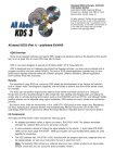
The STEVAL-IFN003V1 is a demonstration board based on STMicroelectronic's ARM™
Cortex-M3 core-based STM32F103CB microcontrollers and the DMOS fully integrated
L6230 3-phase motor driver implementing a field oriented control (FOC) of the PMSM
motor.
It is designed as an evaluation environment for motor control application in the range of
8 V - 48 V of DC bus voltage (which is extendable up to 52 V) and nominal power up to
45 W, exploiting the computational power of STM32F103CB microcontrollers with internal
20 kB SRAM and 128 kB Flash, SWD debugging and the L6230 DMOS driver with 2.8 A
output peak current, non-dissipative overcurrent detection/protection, cross conduction
protection, uncommitted comparator, thermal shutdown, and undervoltage lockout.
The STEVAL-IFN003V1 is provided with a USB interface specific to real-time data
exchange.
With dedicated hardware evaluation features, the STEVAL-IFN003V1 board is designed to
help developers to evaluate the device and to develop their own applications.
The STEVAL-IFN003V1 can be used together with the STM32 PMSM single/dual FOC SDK
v3.0 and constitutes a complete motor control evaluation and development platform.
Figure 1.
March 2012
Image of the board
Doc ID 022378 Rev 1
1/22
www.st.com
Contents
UM1478
Contents
1
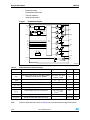
Main features . . . . . . . . . . . . . . . . . . . . . . . . . . . . . . . . . . . . . . . . . . . . . . . 4
2
Electrical characteristics of the board . . . . . . . . . . . . . . . . . . . . . . . . . . 5
3
Schematic, layout and bill of material . . . . . . . . . . . . . . . . . . . . . . . . . . . 6
4
General description . . . . . . . . . . . . . . . . . . . . . . . . . . . . . . . . . . . . . . . . . 11
5
4.1
Power supply . . . . . . . . . . . . . . . . . . . . . . . . . . . . . . . . . . . . . . . . . . . . . . 11
4.2
L6230 power stage . . . . . . . . . . . . . . . . . . . . . . . . . . . . . . . . . . . . . . . . . . 11
4.3
Current sensing circuitry . . . . . . . . . . . . . . . . . . . . . . . . . . . . . . . . . . . . . 13
4.4
STM32F103 microcontroller . . . . . . . . . . . . . . . . . . . . . . . . . . . . . . . . . . . 14
4.5
USB interface . . . . . . . . . . . . . . . . . . . . . . . . . . . . . . . . . . . . . . . . . . . . . . 15
Using the STEVAL-IFN003V1 with the STM32 FOC firmware library . 15
5.1
Hardware requirements . . . . . . . . . . . . . . . . . . . . . . . . . . . . . . . . . . . . . . 16
5.2
Software requirements . . . . . . . . . . . . . . . . . . . . . . . . . . . . . . . . . . . . . . . 16
5.3
STM32 FOC firmware library v3.0 customization . . . . . . . . . . . . . . . . . . . 17
6
References . . . . . . . . . . . . . . . . . . . . . . . . . . . . . . . . . . . . . . . . . . . . . . . . 20
7
Revision history . . . . . . . . . . . . . . . . . . . . . . . . . . . . . . . . . . . . . . . . . . . 21
2/22
Doc ID 022378 Rev 1
UM1478
List of figures
List of figures
Figure 1.
Figure 2.
Figure 3.
Figure 4.
Figure 5.
Figure 6.
Figure 7.
Figure 8.
Figure 9.
Image of the board . . . . . . . . . . . . . . . . . . . . . . . . . . . . . . . . . . . . . . . . . . . . . . . . . . . . . . . . 1
STEVAL-IFN003V1 schematic - MCU, power stage and current sensing circuitry . . . . . . . 6
STEVAL-IFN003V1 schematic - USB controller and power supply . . . . . . . . . . . . . . . . . . . 7
STEVAL-IFN003V1 board layout - top and inner 1 layers . . . . . . . . . . . . . . . . . . . . . . . . . . 8
STEVAL-IFN003V1 board layout - inner 2 and bottom layers . . . . . . . . . . . . . . . . . . . . . . . 8
Power supply section . . . . . . . . . . . . . . . . . . . . . . . . . . . . . . . . . . . . . . . . . . . . . . . . . . . . . 11
L6230 block diagram . . . . . . . . . . . . . . . . . . . . . . . . . . . . . . . . . . . . . . . . . . . . . . . . . . . . . 12
Current sensing circuitry . . . . . . . . . . . . . . . . . . . . . . . . . . . . . . . . . . . . . . . . . . . . . . . . . . . 13
STM32F103xx performance line block diagram . . . . . . . . . . . . . . . . . . . . . . . . . . . . . . . . . 15
Doc ID 022378 Rev 1
3/22
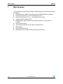
Main features
1
UM1478
Main features
The characteristics of the STEVAL-IFN003V1 PMSM field oriented control driver board are
the following:
4/22
●
STMicroelectronic's ARM™ Cortex-M3 core-based STM32F103xB microcontroller
●
DC voltage range from 8 V to 48 V (extendable up to 52 V)
●
Maximum load current of 1.4 Ar.m.s. (2.8 A peak) for each output
●
Integrated DC-DC regulator (3.3 V)
●
Monolithic power stage in PowerSO package featuring overcurrent and thermal
protection
●
3-shunt current sensing
●
Control interface through trimmer, buttons and USB interface
●
Debug outputs
●
Hall sensor/encoder inputs
●
Optimized layout on 4-layer board for high thermal performance.
Doc ID 022378 Rev 1
UM1478
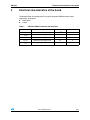
2
Electrical characteristics of the board
Electrical characteristics of the board
The demonstration kit is designed to fit all typical low-power PMSM brushless motor
applications, for example:
●
Cooling fans
●
Pumps
Table 1.
STEVAL-IFN003V1 electrical characteristics
Parameter
Description
Value
Unit
VS, Max
Maximum motor supply voltage
48 (1)
V
VS, Min
Minimum motor supply voltage
8
V
Iout
Maximum output current
1.4
Ar.m.s.
Iout, peak
Maximum output peak current
2.8
A
Tj, op
Operating temperature
-25 to +125 °C
°C
1. Extendable to 52 V, refer to Section 4.1.
Doc ID 022378 Rev 1
5/22
Doc ID 022378 Rev 1
5
5
N
&
S)9
5
N
5
N
,&769$,'76623
5
9''B0&8
5
.
6(16(
63(('
67$57
'$&B287
'$&B287
23287
(QF=
5
N
8&
5
5
N
&
S)9
5
N
5
N
5
N
,1
,1
,1
(1
(1
(1
6:',2
5
6(16(
&
Q)9
9''B0&8
(QF=
(QF%
(QF$
&
Q)9
9''B0&8
5
N
,&769$,'76623
9''B0&8
5
N
-3
-3
-3
-3
-3
-3
6:&/.
6:2
9''B0&8
&
Q)9
9''
966
3$ 3$ 3$ 3$ 3$ 3$ 3%
3%
3%
3%
(QF%
(QF$
86$57B5;
86$57B7;
&
S)9
5
10
&3
&3
&3287
',$*(1
5
.
9''B0&8
23287
,1
(1
,1
(1
,1
(1
',$*(1
5
N
8%
/
&
S)9
5
N
5
N
287
287
287
96$
96%
*1'
*1'
*1'
*1'
9&3
9%22 7
5
5
N
5
9''B0&8
6(16(
6(16(
6(16(
,&769$,'76623
9''B0&8
/3'
&3
&3
&3287
,1
(1
,1
(1
,1
(1
',$*(1
8
(3
5
N
8$
9''B0&8
&
Q)9
&
Q)9
%86B)%.
23287
23287
23287
9%$7
3&7$0357&
3&
3&
3'26&,1
3'26&287
1567
966$
9''$
3$ :.83
3$ 3$ 8
&
Q)9
&
S)9
5
10
23287
&
Q)9
9''B0&8
5
5(6(7
670)&%7
9''B0&8
9''B0&8
5
10
9''B0&8
&
S)9
9''
966
3%
3%
3%
3%
3%
3$
3$
3$
3$
3$
&
X)9
&
Q)9
9'$&B287
9'$&B287
5 N
5 N
5 N
3$
3$
3%
3%
3%
3%
3%
%227
3%
3%
966
9''
;
0+]ZLWKVRFNHW
5
N
%86B)%.
5
N
5
N
&
S)9
&
S)9
96
$SSOLFDWLRQUHIHUHQFH
675,330
-
(3
1&
1&
1&
1&
1&
1&
6/22
1&
1&
1&
1&
1&
1&
6(16(
5
:
'
&
5
:
&
Q)9
%$9
Q)9
6(16(
6(16(
6(16(
5
:
&
X)9
Q)9
&
96
Q)9
&
&21
&1
287
287
287
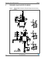
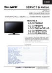
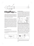
Figure 2.
3
$+
%+
=+
Schematic, layout and bill of material
UM1478
Schematic, layout and bill of material
STEVAL-IFN003V1 schematic - MCU, power stage and current sensing
circuitry
$0Y
Doc ID 022378 Rev 1
&21
96
-
'(%8*
9
675,3[
9
%
(1
(1
9,1
6:
(3
)%
3*22'
*1' (3
5(6(7
'
6736=
&
Q)
8
,&676+623
%227
5 5
5(6(7
5 10
8
&3*0
3$'
1&
1&
1&
1&
1&
1&
1&
'
'
9%86
5(*,1
5
N
5
N
X+
5
N
/
7;'
576
'75
'&'
'65
&76
5,
5;'
9''
&
S)9
5
N
9B86%
&
X)9
6930
26&216$1<2
(65 PRKP
9''B0&8
67$57
*1'
567
6863(1'
6863(1'
(3/0/%&RLOFUDIW
X+$
38/6$17(;0037+
&
Q9
86%/&3
8
&
X)9
80.%-007
7DL\R<XGHQ
&
Q)9
675,330
5 5
-
&1
99
'$&B287
'$&B287
9'$&B287
9'$&B287
86%B6+,(/'
6+
6+
6+
6+
,1'&
)%
&1
0,1,86%%7<&2
&
Q)9
9
1&
1&
1&
1&
67$576723
5
9''B0&8
&
X)9
9
*1'
'
*5((1
73
73
&
Q)9
38/6$17(;0037+
5
%
.
5
9B86%
86$57B5;
9''B0&8
86$57B7;
&
Q)9
5 10
63(('
-
675,330
5
.
$1
$1
$1065
6:2
5(6(7
6:',2
6:&/.
9''B0&8
5
.
41&&%
5
N
9''B0&8
6:'
-
&
Q)9
&3
&3
&3287
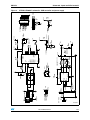
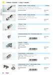
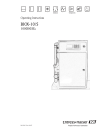
Figure 3.
UM1478
Schematic, layout and bill of material
STEVAL-IFN003V1 schematic - USB controller and power supply
$0Y
7/22
Schematic, layout and bill of material
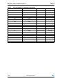
Table 2.
8/22
UM1478
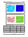
Figure 4.
STEVAL-IFN003V1 board layout - top and inner 1 layers
Figure 5.
STEVAL-IFN003V1 board layout - inner 2 and bottom layers
STEVAL-IFN003V1 bill of material
Reference
Part/value
B1
Button 63 x 45 mm
B2
Button 63 x 45 mm
CN1
3-wire power connector
CN2
Mini-USB type B connector
CN3
2-wire power connector
C1
220 nF/16 V
C2
47 µF/63 V
Doc ID 022378 Rev 1
Manufacturer
Manufacturer code
UM1478
Table 2.
Schematic, layout and bill of material
STEVAL-IFN003V1 bill of material (continued)
Reference
Part/value
C3, C33
100 nF/100 V
C4
10 nF/100 V
C5, C6, C7, C19, C20, C21
10 pF/4 V
C8
4.7 nF/4 V
C9, C10, C15, C16, C17, C18,
C24, C26, C27
100 nF/4 V
C11, C12
22 pF/4 V
C13
1 nF/4 V
C14, C23
1 µF/6.3 V
C22, C25
100 nF/6.3 V
C28, C29
100 nF/100 V
C30
47 µF/6.3 V
C31
820 pF/6.3 V
C32
10 µF/50 V
D1
BAV99
D2
STPS0560Z
D3
Green LED diode
FB1
60 Ω ferrite
J1, J9
Strip line 1 x 3
J2, J3, J4, J5, J6, J7
Jumper SMD 2 x 1
J8
SWD - flat connector 10 x 2
J10
Strip line 1 x 4
J11
Strip line 1 x 2
L1
8.2 µH
R1
470 kΩ
R2, R3, R4, R37, R38
N.M.
R5, R7, R8, R19, R20, R21
4.7 kΩ
R6
470 kΩ
R9
8.2 kΩ
R10
220 Ω
R11
3.3 kΩ
R12, R13, R14
0.33 Ω – 1 W
R15, R16, R17
39 kΩ
R18
100 kΩ
R22, R23, R24, R25, R26, R27
910 Ω
Doc ID 022378 Rev 1
Manufacturer
Manufacturer code
STMicroelectronics
STPS0560Z
Murata
BLM21PG600SN1D
Coilcraft
EPL2010
9/22
Schematic, layout and bill of material
Table 2.
UM1478
STEVAL-IFN003V1 bill of material (continued)
Reference
Part/value
R28, R29, R31, R32, R34, R35
2.7 kΩ
R30, R33, R36, R41, R42
1 kΩ
R39, R47
0Ω
R40, R45, R49
4.7 kΩ
R43
100 Ω
R44
10 kΩ
R46
330 Ω
R48
47 kΩ
R50
2.7 kΩ
TP1
Ring test point
TP2
Ring test point
U1
10/22
Manufacturer
Manufacturer code
L6230
STMicroelectronics
L6230PD
U2
STM32F103CB
STMicroelectronics
STM32F103CBT6
U3
TSV914A
STMicroelectronics
TSV914AIPT
U4
CP2102
Silicon Labs
CP2102-GM
U5
USBLC6-2
STMicroelectronics
USBLC6-2P6
U6
ST1S14
STMicroelectronics
ST1S14PHR
X1
Xtal 8 MHz
Doc ID 022378 Rev 1
UM1478
General description
4
General description
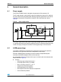
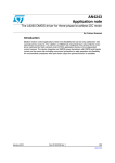
4.1
Power supply
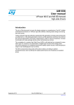
The STEVAL-IFN003V1 board is designed to be powered via CN3 connector 'VS'.
The VS supply voltage is used to directly supply the L6230 power stage and it is applied at
the input of the ST1S14 step-down power switching regulator to generate the 3.3 V able to
supply the microcontroller, the operational amplifiers and the board pull-ups (refer to
Figure 6).
Figure 6.
Power supply section
&
Q9
9''B0&8
-
&1
96
8
676
5 5
&
Q)9
96
99
%227
6:
9,1
3*22'
(1
)%
/
9
X+$
5
5
N
5
N
(1
&
X)9
*1' (3
(3
'
6736=
5
N
&
S)9
'
*5((1
&
X)9
*1'
$0Y
If the system requirements need a power stage supply voltage higher than 48 V (up to 52 V),
it is possible to disconnect the switching regulator from the VS connector removing the R47
resistor and supply it through the connector J5 to keep generating 3.3 V on the board.
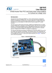
4.2
L6230 power stage
The L6230 is a DMOS fully integrated 3-phase motor driver with overcurrent protection,
optimized for FOC application thanks to the independent current senses.
Realized in BCDmultipower technology, the device combines isolated DMOS power
transistors with CMOS and bipolar circuits on the same chip.
An uncommitted comparator with open drain output is available (refer to the demonstration
board schematic in Figure 2).
●
Features:
–
Operating supply voltage from 8 to 52 V
–
2.8 A output peak current (1.4 A RMS)
–
RDS(on) 0.73 Ω typ. value @ TJ = 25 °C
–
Integrated fast freewheeling diodes
–
Operating frequency up to 100 kHz
–
Non-dissipative overcurrent detection and protection
–
Cross conduction protection
Doc ID 022378 Rev 1
11/22
General description
UM1478
–
Diagnostic output
–
Uncommitted comparator
–
Thermal shutdown
–
Undervoltage lockout
Figure 7.
L6230 block diagram
9%227
9&3
9%227
9%227
96$
7+(50$/
3527(&7,21
&+$5*(
3803
2&'
2&'
287
9
2&'
2&'
2&'
6(16( 9%227
',$*(1
2&'
*$7(
/2*,&
,1
(1
287
9
,1
(1
6(16( 9%227
,1
96%
(1
9
9
2&'
287
9
92/7$*(
5(*8/$725
6(16(
&3287
&3
&3
&203$5$725
$0Y
Table 3.
L6230 absolute maximum ratings
Symbol
Parameter
Conditions
Value
Unit
VS
Supply voltage
VSA = VSB = VS
60
V
60
V
VS + 10
V
VOD
Differential voltage between: VSA, OUT1, OUT2, VSA = VSB = VS = 60 V;
SENSEA and VSB, OUT3, SENSEB
VSENSEx = GND
VBOOT
Bootstrap peak voltage
VIN, VEN
Logic inputs voltage range
-0.3 to +7
V
VCP-, VCP+
Voltage range at CP- and CP+ pins
-0.3 to +7
V
VSENSE
Voltage range at SENSEx pins
-1 to +4
V
IS(peak)
Pulsed supply current (for each VS pin)
VSA = VSB = VS;
TPULSE < 1 ms
3.55
A
IS
RMS supply current (for each VS pin)
VSA = VSB = VS
1.4
A
Tstg, TOP
Storage and operating temperature range
-40 to 150
°C
Note:
12/22
VSA = VSB = VS
Stresses above the limits shown in Table 3 may cause permanent damage to the device.
Doc ID 022378 Rev 1
UM1478
General description
The L6230 integrates a non-dissipative overcurrent detection circuit (OCD) for full
protection.
To implement the overcurrent detection, a sensing element that delivers a small but precise
fraction of the output current is implemented with each high-side Power MOSFET. This
current is compared with an internal reference current IREF.
When the output current reaches the detection threshold (typ. ISOVER = 2.8 A), the OCD
comparator signals a fault condition. When a fault condition is detected, an internal open
drain MOSFET connected to pin DIAG-EN is turned on.
The DIAG-EN pin is used to signal the fault condition to an MCU and to shut down the
3-phase bridge simply by connecting the pin to an external R-C network (R11 - C13).
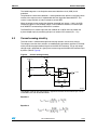
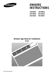
4.3
Current sensing circuitry
The load current is monitored through three sensing resistors, one for each channel.
The voltage across the shunt resistors are conditioned by operational amplifiers (TSV914A)
which provide the proper feedback signals to the MCU A-D converter. The op amp output
voltage range is optimized for a given phase current range and the MCU A-D converter input
dynamics (refer to Figure 8).
Figure 8.
Current sensing circuitry
IURP/
6(16([SLQ
9''B0&8
5F
N
5D
8
:
5VHQVH
769$
5E
WR0&8
5G N
5H
5H
N
N
S9
$0Y
The voltage at the op amp output which is applied to the MCU A-D converter input can be
calculated as the sum of two contributes:
Equation 1
Equation 2
Doc ID 022378 Rev 1
13/22
General description
UM1478
With the mounted resistor values this gives:
●
●
V_bias=1.86 V
V signal = 2,92 ⋅ R sense ⋅ I
The maximum current manageable without distortion is equal to:
Equation 3
Note that the IMAX value can be modified by simply changing the value of the sense
resistors.
4.4
STM32F103CB microcontroller
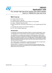
The STM32F103xx performance line family incorporates the high-performance ARM
Cortex™-M3 32-bit RISC core operating at a 72 MHz frequency, high-speed embedded
memories (Flash memory up to 128 Kbytes and SRAM up to 20 Kbytes), and an extensive
range of enhanced I/Os and peripherals connected to two APB buses. All devices offer two
12-bit ADCs, three general purpose 16-bit timers plus one PWM timer, as well as standard
and advanced communication interfaces: up to two I2Cs and SPIs, three USARTs, a USB
and a CAN.
The STM32F103xx medium-density performance line family operates from a 2.0 to 3.6 V
power supply. It is available in both the -40 to +85 °C temperature range and the -40 to +105
°C extended temperature range. A comprehensive set of power-saving modes allows the
design of low-power applications.
The STM32F103xx medium-density performance line family includes devices in 5 different
package types: from 36 pins to 100 pins. Depending on the device chosen, different sets of
peripherals are included. Please refer to the STM32F103xB datasheet for an overview of the
complete range of peripherals proposed in this family.
Figure 9 shows the general block diagram of the device family.
It is possible to get more information regarding the features of the microcontroller and its
operating mode in the STM32F103xx reference manual.
14/22
Doc ID 022378 Rev 1
UM1478
Using the STEVAL-IFN003V1 with the STM32 FOC firmware library
STM32F103xx performance line block diagram
73,8
6:-7$*
,EXV
&RUWH[0&38
)PD[ 0 +]
19,&
7UDFH
&RQWUROOH U
SEX V
7UDFHWULJ
'EXV
6\VW HP
$+%) PD[ 0+]
#9''$
6833/<
683(59,6,21
1567
9''$
966$
5VW
39'
,QW
$+%
$3%
*3,2$
3%> @
*3,2%
3&>@
*3,2&
3'>@
*3,2'
3(>@
*3,2(
&KDQQ HOV
FR PSO&KDQQ HOV
(75DQG%.,1
7,0
026,0,62
6&.166DV$)
63,
#9''
3// &/2&.
0$1$*7
;7$/ 26&
0+]
,:'*
6WDQG E\
LQ WHUIDFH
#9''$
;7$/ N+]
$+%
$3% 57&
$:8
%DFN XS
UHJ
EL W $'& ,)
26&B,1
26&B287
7$03(557&
%DFNX SL QWHUI DFH
7,0
&KDQQ HOV
7,0
&KDQQ HOV
7,0
&KDQQ HOV
86$57
5;7;&76576
&.6PDUW&DUGDV$)
86$57
5;7;&76576
&.6PDUW&DUGDV$)
[[ELW63,
026,0,626&.166
DV$)
,&
6&/6'$60%$
DV$)
,&
6&/6'$
DV$)
E[&$1
86%)6
95()
9%$7
#9%$7
#9''$
ELW $'& ,)
26&B,1
26&B287
5&0+]
5&N+]
86$57
$)
95()
9'' WR9
966
#9''
ELW
(;7,
:$.(83
3$> @
5;7;&76576
6PDUW &DUG DV$)
)ODVK .%
3&/.
3&/.
+&/.
)&/.
$3%) PD[ 0+]
$)
3253'5
92/75(*
9729
65$0
.%
*3'0$
FKDQQHOV
32:(5
$3% )PD[ 0+]
1-7567
7567
-7',
-7&.6:&/.
-7066:',2
-7'2
DV$)
IODVK REO
,QWH UIDF H
75$&(&/.
75$&('>@
DV$6
%XV0 DWUL[
Figure 9.
86%'3&$1B7;
86%'0&$1B5;
65$0%
::'*
7H PSVHQVRU
$0Y
4.5
USB interface
The CP2102 is a highly-integrated USB-to-UART bridge controller providing a simple
solution for updating RS-232 designs to USB using a minimum of components and PCB
space. The CP2102 includes a USB 2.0 full-speed function controller, USB transceiver,
oscillator, EEPROM, and asynchronous serial data bus (UART) with full modem control
signals. No other external USB components are required.
For more details refer to the CP2102 device datasheet.
5
Using the STEVAL-IFN003V1 with the STM32 FOC
firmware library
The “STM32 FOC firmware library v3.0” provided together with the STM3210B-MCKIT
performs the field oriented control (FOC) of a permanent magnet synchronous motor
(PMSM) in both sensor and sensorless configurations.
Doc ID 022378 Rev 1
15/22
Using the STEVAL-IFN003V1 with the STM32 FOC firmware library
UM1478
It is possible to configure the firmware to work with the STEVAL-IFN003V1 board and to
establish a real-time communication for debugging/tuning purposes using the ST motor
control workbench release 1.1 or higher.
This section describes the customization to be applied to the “STM32 FOC firmware library
v3.0” in order for the firmware to be compatible with the STEVAL-IFN003V1 and with the ST
motor control workbench release 1.1 or higher.
5.1
Hardware requirements
The following items are required to run the STEVAL-IFN003V1 together with the “STM32
FOC firmware library”:
5.2
●
The STEVAL-IFN003V1 board
●
A DC power supply (up to 48 V)
●
A programmer/debugger dongle for the control board (not included in the package). To
program/debug the STEVAL-IFN003V1, a dongle with single wire debugging
capabilities (SWD) is required. Use of an insulated dongle is always recommended.
●
A 3-phase brushless motor with permanent magnet rotor (not included in the package)
●
A USB cable with mini-USB connector (type B) to establish a real-time communication
(not included in the package).
●
An insulated oscilloscope (as needed)
●
An insulated multimeter (as needed).
Software requirements
To customize, compile and download the “STM32 FOC firmware library v3.0”, a tool chain
must be installed. Please refer to the UM1052 user manual for major details on how to set
up the proper tool chain.
Please consider that, as is, the “STM32 FOC firmware library v3.0” isn't fully compatible with
either the STEVAL-IFN003V1 or the ST motor control workbench version 1.1 or higher.
In order to establish a real-time communication with the ST motor control workbench, it is
necessary to install the firmware patch “STEVAL-IFN003V1_Patch.exe”, available for
download on the ST website.
Installing the “STEVAL-IFN003V1_Patch.exe” firmware patch enables the functionality of the
“START/STOP” button and of the “SPEED” potentiometer.
Please note that is not advisable to install the firmware patch in the installation folder of FOC
SDK v3.0 because the process is not reversible. It is advised to save the patch in a folder
containing a copy of that directory and remember to create a backup copy of that folder
before installing.
To summarize, the guidelines below can be followed:
16/22
●
Copy the FOC SDK v3.0 installation folder (the default path is “C:\Program
Files\STMicroelectronics\STM32 PMSM FOC Firmware Library v3.0” or similar)
including the subfolder in a working folder (example “C:\Working\IFN003V1\”)
●
Apply the “STEVAL-IFN003V1_Patch.exe” firmware patch in the working folder
(example “C:\Working\IFN003V1\ STM32 PMSM FOC Firmware Library v3.0”).
Doc ID 022378 Rev 1
UM1478
Using the STEVAL-IFN003V1 with the STM32 FOC firmware library
Before establishing the real-time communication it is also necessary to install the “CP210x
USB to UART Bridge VCP drivers” available for download on the “Silicon Labs” website
(http://www.silabs.com).
5.3
STM32 FOC firmware library v3.0 customization
To customize the STM32 FOC firmware library v.3.0 for the STEVAL-IFN003V1, use the “ST
motor control workbench” as described in the UM1052 user manual.
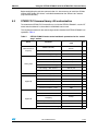
The required parameters for the control stage section related to the STEVAL-IFN003V1 are
reported in Table 4.
Table 4.
STEVAL-IFN003V1 motor control workbench parameters for the “control
stage” section
Block
MCU and clock
frequency
Parameter
STEVAL-IFN003V1 default
value
STM32 sub-family
Performance line medium
density
CPU frequency
72
MHz
Nominal MCU supply voltage
3.30
V
ADC channel selection for phase U
ADC12_IN0
ADC channel selection for phase V
ADC12_IN1
ADC channel selection for phase W
ADC12_IN2
ADC channel for current reading (1sh)
Disabled
Bus voltage – ADC channel
ADC12_IN3
Temp. feedback – ADC channel
Disabled
DAC functionality peripheral
-
Timer
TIM1
TIM1 remapping
No remap
Encoder interface – timer
TIM3
Encoder interface – timer remap
Partial re-map
Hall sensor interface – timer
TIM3
Hall sensor interface – timer remap
Partial re-map
Serial communication – channel
USART1
Serial communication – USART1
remapping
Remap
Dissipative brake output
Disabled
In-rush current limiter
Disabled
Overcurrent protection disabling
Disabled
Unit
Analog input
DAC functionality
Digital I/O
Digital I/O
Doc ID 022378 Rev 1
17/22
Using the STEVAL-IFN003V1 with the STM32 FOC firmware library
Note:
UM1478
In the “Drive management” section, “User Interface Add-on”, the “Joystick, LCD, button”
check box must be unchecked because the feature is not supported by the STEVALIFN003V1. Moreover, the “Serial communication” check box must be checked to enable the
real-time communication.
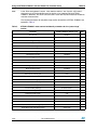
The required parameters for the power stage section related to the STEVAL-IFN003V1 are
reported in Table 5.
Table 5.
18/22
STEVAL-IFN003V1 motor control workbench parameters for the “power stage”
section
Parameter
STEVAL-IFN003V1 default value
ICL shut-out
Disabled
Dissipative brake
Disabled
Bus voltage sensing
Enabled
Bus voltage divider
125
Min. rated voltage
8
V
Max. rated voltage
48
V
Nominal voltage
Equal to the bus voltage provided
V
Temperature sensing
Disabled
V0
-
mV
T0
-
°C
ΔV/ΔT
-
mV/°C
Max. working temperature on sensor
-
°C
Overcurrent protection
Enabled
Comparator threshold
0.50
V
Overcurrent network gain
0.33
V/A
Expected overcurrent threshold
1.5152
A
Overcurrent feedback signal polarity
Active low
Overcurrent protection disabling network
Disabled
Current sensing
Enabled
Current reading topology
3-shunt resistors
Shunt resistor(s) value
0.33
Amplifying network gain
2.76
T-noise
1000
ns
T-rise
1000
ns
Power switches, min. dead-time
700
ns
Power switches, max. switching frequency
100
kHz
U,V,W driver, high-side driving signal
Active high
Doc ID 022378 Rev 1
Unit
Ω
UM1478
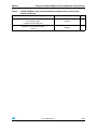
Table 5.
Using the STEVAL-IFN003V1 with the STM32 FOC firmware library
STEVAL-IFN003V1 motor control workbench parameters for the “power stage”
section (continued)
Parameter
STEVAL-IFN003V1 default value
U, V, W driver,
Low-side driving signal.
Complemented from high-side
Enabled
U,V,W Driver, low-side driving signal.
Polarity
Disabled
Doc ID 022378 Rev 1
Unit
19/22
References
6
UM1478
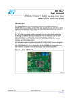
References
This user manual provides information on the hardware features and use of the
STEVAL-IFN003V1 demonstration board. For additional information on supporting software
and tools, refer to the following:
1.
20/22
STM32F103xB datasheet
2.
RM0008 reference manual (STM32F103xx)
3.
UM1052 user manual
4.
L6230 datasheet
5.
ST1S14 datasheet
6.
TSV914A datasheet
7.
http://www.st.com/mcu/ web site, which is dedicated to the complete
STMicroelectronics microcontroller portfolio.
Doc ID 022378 Rev 1
UM1478
7
Revision history
Revision history
Table 6.
Document revision history
Date
Revision
14-Mar-2012
1
Changes
Initial release.
Doc ID 022378 Rev 1
21/22
UM1478
Please Read Carefully:
Information in this document is provided solely in connection with ST products. STMicroelectronics NV and its subsidiaries (“ST”) reserve the
right to make changes, corrections, modifications or improvements, to this document, and the products and services described herein at any
time, without notice.
All ST products are sold pursuant to ST’s terms and conditions of sale.
Purchasers are solely responsible for the choice, selection and use of the ST products and services described herein, and ST assumes no
liability whatsoever relating to the choice, selection or use of the ST products and services described herein.
No license, express or implied, by estoppel or otherwise, to any intellectual property rights is granted under this document. If any part of this
document refers to any third party products or services it shall not be deemed a license grant by ST for the use of such third party products
or services, or any intellectual property contained therein or considered as a warranty covering the use in any manner whatsoever of such
third party products or services or any intellectual property contained therein.
UNLESS OTHERWISE SET FORTH IN ST’S TERMS AND CONDITIONS OF SALE ST DISCLAIMS ANY EXPRESS OR IMPLIED
WARRANTY WITH RESPECT TO THE USE AND/OR SALE OF ST PRODUCTS INCLUDING WITHOUT LIMITATION IMPLIED
WARRANTIES OF MERCHANTABILITY, FITNESS FOR A PARTICULAR PURPOSE (AND THEIR EQUIVALENTS UNDER THE LAWS
OF ANY JURISDICTION), OR INFRINGEMENT OF ANY PATENT, COPYRIGHT OR OTHER INTELLECTUAL PROPERTY RIGHT.
UNLESS EXPRESSLY APPROVED IN WRITING BY TWO AUTHORIZED ST REPRESENTATIVES, ST PRODUCTS ARE NOT
RECOMMENDED, AUTHORIZED OR WARRANTED FOR USE IN MILITARY, AIR CRAFT, SPACE, LIFE SAVING, OR LIFE SUSTAINING
APPLICATIONS, NOR IN PRODUCTS OR SYSTEMS WHERE FAILURE OR MALFUNCTION MAY RESULT IN PERSONAL INJURY,
DEATH, OR SEVERE PROPERTY OR ENVIRONMENTAL DAMAGE. ST PRODUCTS WHICH ARE NOT SPECIFIED AS "AUTOMOTIVE
GRADE" MAY ONLY BE USED IN AUTOMOTIVE APPLICATIONS AT USER’S OWN RISK.
Resale of ST products with provisions different from the statements and/or technical features set forth in this document shall immediately void
any warranty granted by ST for the ST product or service described herein and shall not create or extend in any manner whatsoever, any
liability of ST.
ST and the ST logo are trademarks or registered trademarks of ST in various countries.
Information in this document supersedes and replaces all information previously supplied.
The ST logo is a registered trademark of STMicroelectronics. All other names are the property of their respective owners.
© 2012 STMicroelectronics - All rights reserved
STMicroelectronics group of companies
Australia - Belgium - Brazil - Canada - China - Czech Republic - Finland - France - Germany - Hong Kong - India - Israel - Italy - Japan Malaysia - Malta - Morocco - Philippines - Singapore - Spain - Sweden - Switzerland - United Kingdom - United States of America
www.st.com
22/22
Doc ID 022378 Rev 1