1
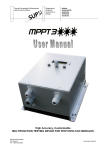
Pickup Winding Machine User Manual FEATURES Heavy duty 24VDC geared motor High efficiency dual H bridge motor driver uController controlled speed, direction, and turns 10 programmable and savable banks Approx 1800 RPM max speed Magnet Gauss sensor Backlit blue LCD screen Powder coated metal casing Optional foot control 110v to 220vAC adaptor Adjustable manual traverse Universal pickup mounting jig Made in the U.S.A. FRONT CONTROLS SPEED Controls speed manually from 060. (~01800rpm) PROGRAM Opens the program mode for editing and saving winding direction or number of turns. DOWN/RUN STOP “DOWN” selects NO, decreases number of turns, selects Dir C, and scrolls down in program mode. “RUN STOP” starts and stops run mode. UP/GAUSS “UP” selects YES, increases number of turns, selects Dir CC, and scrolls up in program mode. “GAUSS” opens and closes the Gauss sensor mode. SIDE CONTROLS SPEED (control out) Bypasses manual front panel speed control for optional foot pedal (not included). This jack is a standard TRS connection of 5V control voltage. 5Vdc is wired to the tip 0Vdc is wired to the sleeve and the ring connection expects 05Vdc which is used to set the speed of the unit. At 0vDC the motor shaft is in “coast” state. Any control voltage pedal can be used although all testing was done with a Behringer FCV100. A volume pedal can also be used but requires custom wiring of 2 x ¼” TS plugs to 1 ¼” TRS plug. IMPORTANT! Care must be take to connect this cable so that the input tip is connected to the TRS tip and the output tip to the TRS ring. It is possible to damage the unit or your volume pedal if this wiring is not fully understood so we can only recommend the use of a FCV100 and a TRS to TRS cable. Only plug and unplug when the machine is off. RUN STOP This is a footswitch jack for the RUN Stop button on the front panel. It is a 2 wire connection where the tip is momentarily grounded to the sleeve to control Run mode. It is notable that coming out of Run mode or ending the turns count which also exits run mode “brakes” the motor instead of “coast”. 1 GETTING STARTED Attach Mounting Jig Attach the mandrel to the motor shaft using the set screw against the notch on the motor shaft. Mount the traverse bar on other side of the clamp. We mount it on the opposite side for shipping purposes only. Attach Bobbin After mounting the mandrel, attach the bobbin to the mounting jig by sliding the center hole of the bobbin over the threaded 440 center post. For bobbins without center holes, you can use the closest hole to the center. Remember the bobbin is not perfectly round, so mounting it perfectly on center is not critical because the bobbin is spinning oblong anyway. Attach the outer clamp over the threaded rod and bobbin so that the hollow channel goes around any protruding magnets. Then fasten the brass thumb screw snug against the clamp so that the bobbin will not spin or come loose. Do not overtighten because it may crush or damage the bobbin. NOTE: You can also remove the center post from the mounting jig by unscrewing the post out from the bottom. You can access it through the center hole of the mandrel while it is removed from the motor shaft. This allows you to use double sided carpet tape on the flat bar to secure any bobbins without having to use the clamp and post. POWER ON Plug power adaptor (included) into the machine and then into the wall outlet. The green light on the adaptor will illuminate showing there is power. Turn the machine on and you will see the LCD display screen light up blue with moving text “Mojotone P’up Winder V2.0”. Then the display will read “Dir C Speed 060”. The initial number of turns will always default to Preset 1 when the machine is first turned on. We program “Preset 1” to 10000 turns from the factory. You will need to program the presets to your desired number of turns after you purchase the machine. PROGRAMMING BANKS Step 1 : Press “PROGRAM” to open program mode. It will display “Use last turns? DOWN=NO UP=YES”. Select “NO” to continue through program mode. Select “YES” if you want to repeat the last program you just completed. Step 2 : Your screen will now display “Dir C”. Push “UP” to select CC for Counterclockwise direction, or push “DOWN” to select C for Clockwise direction. Step 3 : Press “PROGRAM” and it will display “Turns #”. Push “UP” or “DOWN” to change the number of turns. NOTE: Holding the button down will shift the numbers in increments of 1’s, then 10’s and then 100’s. Step 4 : Press “PROGRAM” button again and it will display “Use Presets? DOWN=NO UP=YES”. Select “UP” and it will display “Save/Restore set with up/down”. Step 5 : Press “UP” or “DOWN” to run through the different banks. The menu starts with “No Action” and continues up with “Save Preset 110” followed by “Restore Preset 110”. Step 6 : “No Action” followed by pressing the “PROGRAM” button will cancel out of program mode and default the machine back to the initial power on settings. Step 7 : Scroll through “Save Preset 110” to the desired bank. Follow by pressing the “PROGRAM” button. Then it will ask you “Save Turns to Preset #”. Step 8: Push “UP” to save the number of turns from Step 2 to the bank. This will override anything previously saved to that bank. The display will read the turn direction, speed, and number of turns you set in steps 1 and 2. Step 9 : Press “RUN STOP” to start or stop winding with the program. RESTORING BANKS Step 1 : Press “PROGRAM” to open program mode. It will display “Use last turns? DOWN=NO UP=YES”. Select “NO” to continue through program mode. Select “YES” if you want to repeat the last program you just completed. Step 2 : Your screen will now display “Dir C”. Push “UP” to select CC for Counterclockwise direction, or push “DOWN” to select C for Clockwise direction. Step 2 : Press “PROGRAM” button twice, passing over “Turns #”, until the display reads “Use Presets? DOWN=NO UP=YES”. Select “UP” and it will display “Save/Restore set with up/down”. Step 3 : Press “UP” or “DOWN” to run through the different banks. The menu starts with “No Action” and continues up with “Save Preset 110” followed by “Restore Preset 110”. Step 4 : “No Action” followed by pressing the “PROGRAM” button will cancel out of program mode and default the 2 machine back to the initial power on settings. Step 5 : Scroll through “Restore Preset 110” to the desired bank. Follow by pressing the “PROGRAM” button. Then it will ask you “Restore Preset # to Turns ?”. Step 6 : Push “UP” to restore the number of turns saved to that bank. Step 7 : Press “RUN STOP” to start or stop winding with the program. WINDING PARAMETER Use a straightedge from the inside edges of the bobbin to the bar and adjust the collars against the straightedge to set your inside winding parameter. Tighten the set screws gently against the flattened portion of the bar after the desired parameter is set. Now you can feed the wire in between the collars to build the coil evenly. We recommend using our Hand Guided Tensioner Tool to guide the wire under the bar for “C” Clockwise bobbin rotation, and over the bar for “CC” Counter Clockwise bobbin rotation. START WINDING After setting the machine to the desired winding direction and number of turns, you can begin winding the coil. To begin, press “RUN STOP” to run the program. Make sure that you have the speed control set at 0 before starting or it will immediately jump to the set speed and may result in wire breakage. Slowly increase your speed using the speed knob or optional foot control pedal to the desired speed. You can adjust speed up or down from 060 anytime during the program. The machine will count down and stop immediately at 0 turns after the program is finished, so it is recommended that you slow the speed down as your number of turns approach close to 0. Once the machine stops at 0, you can choose to run the same program again by pressing “PROGRAM”, then it will display, “Use Last Prog? Down=No Up=Yes.” Press “UP” to run the last program again, or press “DOWN” to program a different winding direction and number of turns from the last saved program. NOTEOnce you turn the machine off and back on again, the machine will default back to preset 1 turns and turn direction C. GAUSS SENSOR Press “GAUSS” button to open the gauss sensor mode. Press again to exit the gauss sensor mode. You must stop the current program you are running before entering the Gauss sensor mode. The Gauss sensor selfcalibrates to “0” so you cannot have a magnet touching the sensor until after you open the Gauss sensor mode and it shows calibrated to “0”. Place the magnet or directly against the center of the sensor on the top of the machine labeled “GAUSS SENSOR” to read the polarity and Gauss level. The magnet side touching the sensor is displayed as North or South polarity. Placing very powerful magnets (rare earth magnets for example) on the Gauss meter will cause the LCD screen to be disrupted and is therefore not recommended. NOTE***Please understand that Gauss levels are relative readings (based on whatever meter you are using and how it was calibrated) and should not be compared with readings stated by other Gauss meter or magnet manufacturers. We recommend you measure only with our Gauss sensor to record readings of fully magnetized magnets if you want to compare Gauss levels. It is perfectly normal to see slight variations of Gauss levels throughout the entirety of the magnet or even stronger Gauss readings from the edges. If the gauss level shows a significantly lower reading, make sure you try repositioning the magnet on the sensor until the highest number is achieved. If you continue to get major differences in Gauss readings, try remagnetizing the magnet and repeat the above until relatively consistent readings are achieved. 3 WINDING TIPS Super glue your flatwork and magnets together. This strengthens the assembly of the bobbin and helps prevent moisture from getting between the flatwork and magnets. Sand or scrape any rough edges on the bobbin before winding to prevent wire snags or breakage. Tape your magnets on Fender style single coil bobbins. Thin paper tape or Kapton tape works well and helps prevent dead shorts directly against the magnets. Feed the coil wire off of one end of the spool from the floor. A small plastic bucket/container with a smooth edged center hole (grommet) through the lid to feed the wire, helps prevent the wire from flying out and catching something as it feeds off of the spool. For consistency, use our Hand Guided Tensioner Tool for better control over your tension and winding pattern. WARRANTY Mojotones’ warranty obligations are limited to the terms set forth below: Mojotone, as defined below, warrants this Mojotone branded winding machine against defects in materials and workmanship under normal use for a period of ONE (1) YEAR from the date of retail purchase by the original enduser purchaser (“Warranty Period”). If a defect arises and a valid claim is received within the Warranty Period, at its option, Mojotone will either (1) repair the hardware defect at no charge, using new or refurbished replacement parts, or (2) exchange the product with a product that is new or which has been manufactured from new or serviceable used parts and is at least functionally equivalent to the original product. Mojotone may request that you replace defective parts with new or refurbished userinstallable parts that Mojotone provides in fulfilment of its warranty obligation. A replacement product or part, that has been installed in accordance with instructions provided by Mojotone, assumes the remaining warranty of the original product or ninety (90) days from the date of replacement or repair, whichever provides longer coverage for you. When a product or part is exchanged, any replacement item becomes your property and the replaced item becomes Mojotones’ property. EXCLUSIONS AND LIMITATIONS This warranty does not apply: (a) to damage caused by use with nonMojotone products; (b) to damage caused by accident, abuse, misuse, flood, fire, earthquake or other external causes; (c) to damage caused by operating the product outside the permitted or intended uses as described by Mojotone; (d) to damage caused by service (including upgrades and expansions) performed by anyone who is not a representative of Mojotone; (e) to a product or part that has been modified to significantly alter functionality or capability without the written permission of Mojotone; (f) if any Mojotone serial number has been removed or defaced. OBTAINING WARRANTY SERVICE Service options, parts availability and response times will vary according to country. You may be responsible for shipping and handling charges if the product cannot be serviced in the country it is in. In accordance with applicable law, Mojotone requires that you furnish proof of purchase details before receiving warranty service. © Copyright 2015. Mojotone® is a registered trademark of Nothing Shocking LLC DBA Mojo Musical Supply. 513 South Dudley St, Burgaw, North Carolina 28425 Toll Free: (800) 9276656 Local: (910) 2597291 Fax: (910) 2597292 Website: www.mojotone.com 4