1
Allen-Bradley
AtomScan + Bar
Code Readers
(Cat. Nos. 2755-LS7-SA,
2755-LS7-SB,
2755-LS7-RA,
2755-LS7-RB,
2755-LS7-SBV, and
2755-LS7-RBV)
User
Manual
Important User
Information
Because of the variety of uses for the products described in this
publication, those responsible for the application and use of this
control equipment must satisfy themselves that all necessary steps
have been taken to assure that each application and use meets all
performance and safety requirements, including any applicable laws,
regulations, codes and standards.
The illustrations, charts, sample programs and layout examples
shown in this guide are intended solely for purposes of example.
Since there are many variables and requirements associated with any
particular installation, Allen-Bradley does not assume responsibility
or liability (to include intellectual property liability) for actual use
based upon the examples shown in this publication.
Allen-Bradley publication SGI-1.1, Safety Guidelines for the
Application, Installation, and Maintenance of Solid-State Control
(available from your local Allen-Bradley office), describes some
important differences between solid-state equipment and
electromechanical devices that should be taken into consideration
when applying products such as those described in this publication.
Reproduction of the contents of this copyrighted publication, in
whole or in part, without written permission of Allen-Bradley
Company, Inc., is prohibited.
Throughout this manual we use notes to make you aware of safety
considerations:
!
ATTENTION: Identifies information about practices
or circumstances that can lead to personal injury or
death, property damage or economic loss.
Attention statements help you to:
• identify a hazard
• avoid the hazard
• recognize the consequences
Important:
Identifies information that is critical for successful
application and understanding of the product.
PLC-5 and PHOTOSWITCH are registered trademarks of Allen-Bradley, Inc.
SLC 5/03, SLC 5/04, MicroLogix, and DTAM are trademarks of Allen-Bradley Company, Inc.
DeviceNet is a trademark of the Open DeviceNet Vendor Association
Windows is a trademark of Microsoft
Table of Contents
Preface
Chapter Objectives . . . . . . . . . . . . . . . . . . . . . . . . . . . . . . . . . . .
Contents of this Manual . . . . . . . . . . . . . . . . . . . . . . . . . . . . . . . .
Conventions Used in this Manual . . . . . . . . . . . . . . . . . . . . . . . . .
Intended Audience . . . . . . . . . . . . . . . . . . . . . . . . . . . . . . . . . . . .
Related Publications . . . . . . . . . . . . . . . . . . . . . . . . . . . . . . . . . .
Technical Support Services . . . . . . . . . . . . . . . . . . . . . . . . . . . . . .
Introduction to AtomScan+
Bar Code Readers
Chapter 1
Hardware Features
Chapter 2
Required Tools and Equipment . . . . . . . . . . . . . . . . . . . . . . . . . . .
Procedures . . . . . . . . . . . . . . . . . . . . . . . . . . . . . . . . . . . . . . . . .
Reader Features . . . . . . . . . . . . . . . . . . . . . . . . . . . . . . . . . . . . .
Reader LEDs . . . . . . . . . . . . . . . . . . . . . . . . . . . . . . . . . . . . . . .
Interface Box Features . . . . . . . . . . . . . . . . . . . . . . . . . . . . . . . . .
Decoding . . . . . . . . . . . . . . . . . . . . . . . . . . . . . . . . . . . . . . . . . .
Safety Information . . . . . . . . . . . . . . . . . . . . . . . . . . . . . . . . . . . .
Scan Beam Options . . . . . . . . . . . . . . . . . . . . . . . . . . . . . . . . . . .
Accessories . . . . . . . . . . . . . . . . . . . . . . . . . . . . . . . . . . . . . . . .
Designing Your Scanner
System
P–1
P–1
P–2
P–2
P–2
P–2
1–1
1–2
2–1
2–1
2–2
2–3
2–4
2–5
2–5
Chapter 3
Setup Goals . . . . . . . . . . . . . . . . . . . . . . . . . . . . . . . . . . . . . . . .
Symbol Height and Length . . . . . . . . . . . . . . . . . . . . . . . . . . . . . .
Symbol Quality . . . . . . . . . . . . . . . . . . . . . . . . . . . . . . . . . . . . . .
Symbol Orientation . . . . . . . . . . . . . . . . . . . . . . . . . . . . . . . . . . .
Picket Fence and Step Ladder Orientation . . . . . . . . . . . . . . . . .
Tilt, Pitch, and Skew . . . . . . . . . . . . . . . . . . . . . . . . . . . . . . . . . .
Tilt . . . . . . . . . . . . . . . . . . . . . . . . . . . . . . . . . . . . . . . . . . . . .
Pitch . . . . . . . . . . . . . . . . . . . . . . . . . . . . . . . . . . . . . . . . . . . .
Skew . . . . . . . . . . . . . . . . . . . . . . . . . . . . . . . . . . . . . . . . . . .
Determining Read Range . . . . . . . . . . . . . . . . . . . . . . . . . . . . . . .
Catalog Numbers 2755-LS7-SA and 2755-LS7-RA . . . . . . . . . . .
Catalog Numbers 2755-LS7-SB and 2755-LS7-RB . . . . . . . . . . .
Catalog Numbers 2755-LS7-SBV and 2755-LS7-RBV . . . . . . . . .
Calculating the Number of Scans . . . . . . . . . . . . . . . . . . . . . . . . .
Step Ladder Calculation . . . . . . . . . . . . . . . . . . . . . . . . . . . . . .
Picket Fence Calculation . . . . . . . . . . . . . . . . . . . . . . . . . . . . .
3–1
3–2
3–2
3–3
3–3
3–5
3–5
3–5
3–6
3–6
3–7
3–7
3–8
3–9
3–9
3–10
Publication 2755-6.9
toc–ii
Table of Contents
Installing Your Hardware
Chapter 4
Installing the System Hardware . . . . . . . . . . . . . . . . . . . . . . . . . . .
Connecting System Hardware Together When Using
an Interface Box . . . . . . . . . . . . . . . . . . . . . . . . . . . . . . . . . . .
Connecting System Hardware Together When Using
an Interface Box with an Auxiliary Monitor . . . . . . . . . . . . . . . . .
Connecting System Hardware Together When Using
an Interface Box in a Daisy-Chain Configuration . . . . . . . . . . . .
Connecting System Hardware Together When Not Using
an Interface Box . . . . . . . . . . . . . . . . . . . . . . . . . . . . . . . . . . .
Configuring Your Reader
4–8
4–11
4–15
5–1
5–1
5–5
5–9
5–15
5–20
5–23
5–24
5–24
5–25
5–25
5–25
5–26
5–39
5–39
5–39
5–40
5–40
5–40
5–40
5–40
Chapter 6
Using Operational Commands . . . . . . . . . . . . . . . . . . . . . . . . . . .
Program Management Commands . . . . . . . . . . . . . . . . . . . . . .
Device Control Commands . . . . . . . . . . . . . . . . . . . . . . . . . . . .
Code Types Commands . . . . . . . . . . . . . . . . . . . . . . . . . . . . . .
Counter Commands . . . . . . . . . . . . . . . . . . . . . . . . . . . . . . . . .
Test Commands . . . . . . . . . . . . . . . . . . . . . . . . . . . . . . . . . . .
Status Commands . . . . . . . . . . . . . . . . . . . . . . . . . . . . . . . . . .
Master Label Commands . . . . . . . . . . . . . . . . . . . . . . . . . . . . .
Operating Scanner System Hardware . . . . . . . . . . . . . . . . . . . . . .
Operating the Reader . . . . . . . . . . . . . . . . . . . . . . . . . . . . . . . .
Publication 2755-6.9
4–5
Chapter 5
Menu Configuration . . . . . . . . . . . . . . . . . . . . . . . . . . . . . . . . . . .
To Access the Reader Configuration Main Menu . . . . . . . . . . . . .
Communications Menu . . . . . . . . . . . . . . . . . . . . . . . . . . . . . . .
Operations Menu . . . . . . . . . . . . . . . . . . . . . . . . . . . . . . . . . . .
Code Types Menu . . . . . . . . . . . . . . . . . . . . . . . . . . . . . . . . . .
Scanner Output Menu . . . . . . . . . . . . . . . . . . . . . . . . . . . . . . .
Scanner Setup Menu . . . . . . . . . . . . . . . . . . . . . . . . . . . . . . . .
Serial Configuration . . . . . . . . . . . . . . . . . . . . . . . . . . . . . . . . . . .
Serial Configuration Command Format . . . . . . . . . . . . . . . . . . .
Concatenating Serial Commands . . . . . . . . . . . . . . . . . . . . . . .
Serial Command Status Request . . . . . . . . . . . . . . . . . . . . . . .
Losing Communications . . . . . . . . . . . . . . . . . . . . . . . . . . . . . .
Serial Configuration Commands . . . . . . . . . . . . . . . . . . . . . . . .
Decode Test . . . . . . . . . . . . . . . . . . . . . . . . . . . . . . . . . . . . . . . .
Adjusting Reader Parameters . . . . . . . . . . . . . . . . . . . . . . . . . . . .
Scan Rate . . . . . . . . . . . . . . . . . . . . . . . . . . . . . . . . . . . . . . . .
Range . . . . . . . . . . . . . . . . . . . . . . . . . . . . . . . . . . . . . . . . . .
Scan Width . . . . . . . . . . . . . . . . . . . . . . . . . . . . . . . . . . . . . . .
Label Speed . . . . . . . . . . . . . . . . . . . . . . . . . . . . . . . . . . . . . .
Label Dimensions, Label Density, and Label Ratio . . . . . . . . . . .
Gain . . . . . . . . . . . . . . . . . . . . . . . . . . . . . . . . . . . . . . . . . . . .
Hardware Operation
4–2
6–1
6–3
6–4
6–4
6–4
6–5
6–6
6–8
6–9
6–9
Table of Contents
Defaulting the Reader . . . . . . . . . . . . . . . . . . . . . . . . . . . . . . .
Operating the Interface Box . . . . . . . . . . . . . . . . . . . . . . . . . . .
Defaulting the Interface Boxes . . . . . . . . . . . . . . . . . . . . . . . . .
Operating the Power Supply . . . . . . . . . . . . . . . . . . . . . . . . . . .
Operating the Host Device . . . . . . . . . . . . . . . . . . . . . . . . . . . .
Maintenance and
Troubleshooting
Chapter 7
Specifications
Appendix A
Cleaning the Scan Window . . . . . . . . . . . . . . . . . . . . . . . . . . . . . .
Troubleshooting the Readers . . . . . . . . . . . . . . . . . . . . . . . . . . . .
Technical Support Services . . . . . . . . . . . . . . . . . . . . . . . . . . . . . .
Reader Specifications . . . . . . . . . . . . . . . . . . . . . . . . . . . . . . . . .
Interface Box Specifications . . . . . . . . . . . . . . . . . . . . . . . . . . . . .
Power Supply Specifications . . . . . . . . . . . . . . . . . . . . . . . . . . . . .
Cable Pinouts
A–2
A–3
A–3
B–1
B–2
B–2
B–2
B–3
B–3
B–4
C–1
Appendix D
Multidrop Addresses . . . . . . . . . . . . . . . . . . . . . . . . . . . . . . . . . .
Polling Sequence . . . . . . . . . . . . . . . . . . . . . . . . . . . . . . . . . . . . .
Polling Reset . . . . . . . . . . . . . . . . . . . . . . . . . . . . . . . . . . . . . .
Select Sequence . . . . . . . . . . . . . . . . . . . . . . . . . . . . . . . . . . . . .
Select Reset . . . . . . . . . . . . . . . . . . . . . . . . . . . . . . . . . . . . . .
Application Examples
7–1
7–2
7–3
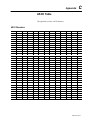
Appendix C
ASCII Characters . . . . . . . . . . . . . . . . . . . . . . . . . . . . . . . . . . . .
Multidrop Communications
6–14
6–14
6–15
6–16
6–16
Appendix B
Reader Cable Pinouts . . . . . . . . . . . . . . . . . . . . . . . . . . . . . . . . .
Interface Box Pinouts . . . . . . . . . . . . . . . . . . . . . . . . . . . . . . . . . .
Trigger Connector . . . . . . . . . . . . . . . . . . . . . . . . . . . . . . . . . .
Power Port . . . . . . . . . . . . . . . . . . . . . . . . . . . . . . . . . . . . . . .
Scanner Port . . . . . . . . . . . . . . . . . . . . . . . . . . . . . . . . . . . . . .
RS-485/422 Port . . . . . . . . . . . . . . . . . . . . . . . . . . . . . . . . . . .
RS-232 Port . . . . . . . . . . . . . . . . . . . . . . . . . . . . . . . . . . . . . .
ASCII Table
toc–iii
D–1
D–3
D–3
D–4
D–4
Appendix E
Enhanced Decoder . . . . . . . . . . . . . . . . . . . . . . . . . . . . . . . . . . .
Hardware Connections for AUX Port Pass-Through . . . . . . . . . .
Configuration Codes for the AUX Port Pass-Through . . . . . . . . .
Enhanced Decoder Setup for the AUX Port Pass-Through . . . . .
Flexible Interface Module . . . . . . . . . . . . . . . . . . . . . . . . . . . . . . .
Hardware Connections for the Flexible Interface Module . . . . . . .
Configuration Codes for the Flexible Interface Module . . . . . . . . .
E–1
E–2
E–2
E–2
E–3
E–4
E–4
Publication 2755-6.9
toc–iv
Table of Contents
Flexible Interface Module Setup . . . . . . . . . . . . . . . . . . . . . . . .
SLC 5/03 and SLC 5/04 Controllers . . . . . . . . . . . . . . . . . . . . . . . .
Hardware Connections for the SLC 5/03 and
SLC 5/04 Controllers . . . . . . . . . . . . . . . . . . . . . . . . . . . . .
Configuration Codes for the SLC 5/03 and SLC 5/04 Controllers .
SLC 5/03 and SLC 5/04 Controllers Setup . . . . . . . . . . . . . . . . .
SLC Program . . . . . . . . . . . . . . . . . . . . . . . . . . . . . . . . . . . . .
PLC-5 Controller . . . . . . . . . . . . . . . . . . . . . . . . . . . . . . . . . . . . .
Hardware Connections for the PLC-5 Controllers . . . . . . . . . . . .
Configuration Codes for the PLC-5 Controllers . . . . . . . . . . . . . .
PLC-5 Controllers Setup . . . . . . . . . . . . . . . . . . . . . . . . . . . . . .
PLC Program . . . . . . . . . . . . . . . . . . . . . . . . . . . . . . . . . . . . .
DTAM Plus DeviceNet . . . . . . . . . . . . . . . . . . . . . . . . . . . . . . . . .
Hardware Connections for the DTAM Plus Operator Interface . . .
Configuration Codes for the DTAM Plus Operator Interface . . . . .
DTAM Plus Operator Interface Setup . . . . . . . . . . . . . . . . . . . . .
DeviceNet Operation . . . . . . . . . . . . . . . . . . . . . . . . . . . . . . . .
European Union Directives
E–8
E–9
E–9
E–10
E–11
E–12
E–12
E–13
E–14
E–14
E–15
E–16
E–16
E–16
Appendix F
Compliance to European Union Directives . . . . . . . . . . . . . . . . . . .
Low Voltage Directive . . . . . . . . . . . . . . . . . . . . . . . . . . . . . . . .
Declaration of Conformity . . . . . . . . . . . . . . . . . . . . . . . . . . . . . . .
Glossary
Publication 2755-6.9
E–5
E–7
F–1
F–1
F–2
Preface
Chapter Objectives
Read this chapter to familiarize yourself with the rest of the manual.
You will learn about:
• contents of this manual
• conventions used in this manual
• intended audience
• related publications
• technical support services
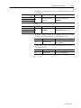
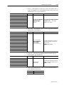
Contents of this Manual
The following table describes the contents of this manual.
Chapter
Title
Contents
Preface
Describes the purpose, background, and scope of
this manual. Also specifies the audience for whom
this manual is intended.
1
Introduction to AtomScan+
Bar Code Readers
Provides an introduction for the use of the
AtomScan+ Bar Code Readers.
2
Hardware Features
Provides an overview of the readers and interface
boxes. Includes a description of accessory items.
3
Designing Your Scanner
System
Provides information needed to design and
implement a scanner system.
4
Installing Your Hardware
Describes how to connect your scanner system
hardware.
5
Configuring Your Reader
Describes configuration options for the reader.
6
Hardware Operation
Describes how to operate your system hardware.
7
Maintenance and
Troubleshooting
Describes how to maintain and troubleshoot your
scanner system hardware.
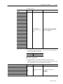
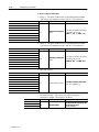
Appendix A
Specifications
Provides physical, electrical, environmental, and
functional specifications for the readers and
interface box.
Appendix B
Cable Pinouts
Lists the cable pinouts for reader cable.
Appendix C
ASCII Table
Lists ASCII conversion chart.
Appendix D
Multidrop
Communications
Describes the rules for setting up a concentrator or
controller to communicate with an AtomScan+ Bar
Code Reader.
Appendix E
Application Examples
Illustrates various applications.
Appendix F
European Union
Directives
Provides requirements for readers when used
within the European Union.
Glossary
Provides terms found within this document.
Publication 2755-6.9
P–2
Preface
Conventions Used in this
Manual
The following conventions are used throughout this manual.
• Bulleted lists such as this one provide information, not procedural
steps.
• Numbered lists provide sequential steps.
• Italic type is used for emphasis.
• Text within square brackets [in this font] represent the keys
you press.
Intended Audience
No special knowledge is required to understand this document or use
the AtomScan+ Bar Code Readers (Catalog Nos. 2755-LS7-SA,
2755-LS7-SB, 2755-LS7-RA, 2755-LS7-RB, 2755-LS7-SBV, and
2755-LS7-RBV).
!
Related Publications
ATTENTION: Use of controls or adjustments or
performance of procedures other than those specified
herein may result in hazardous laser light exposure.
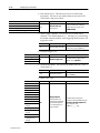
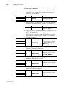
The following table lists the other publication related to the
AtomScan+ Bar Code Readers.
Publication Number
2755-921
Technical Support Services
Title
Bar Code Basics
If you have any questions about the AtomScan+ Bar Code Reader,
please consult this manual first. If you can’t find the answer, contact
Rockwell Automation International Support:
Rockwell International
Technical Support
6680 Beta Drive
Mayfield Village, Ohio 36849
Inside USA and Canada, call 1–800–289–2279.
Outside USA and Canada, contact your Allen-Bradley office or call
USA (216) 646–6800.
Publication 2755-6.9
Chapter
1
Introduction to AtomScan+ Bar
Code Readers
This chapter can help you to get started using the AtomScan+ Bar
Code Readers. We base the procedures here on the assumption that
you have an understanding of bar code scanners and control
equipment.
Because it is an introduction, this chapter does not contain detailed
explanations about the procedures listed. It does, however, reference
other chapters in this book where you can get more information.
If you have any questions or are unfamiliar with the terms used or
concepts presented in the procedural steps, always read the
referenced chapters and other recommended documentation before
trying to apply the information.
This chapter tells you:
• what tools and equipment you need
• procedures for getting your scanner system up and running
Required Tools and
Equipment
Have the following tools and equipment ready:
• screwdriver
• drill
• tape measure
• personal computer with terminal program and an RS-232 cable
Publication 2755-6.9
1–2
Introduction to AtomScan+ Bar Code Readers
Procedures
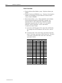
1.
Check the contents of shipping boxes.
Reference
Unpack the shipping boxes making sure that the contents include:
•
AtomScan+ Bar Code Readers (Catalog Nos. 2755-LS7-SA, 2755-LS7-SB, 2755-LS7-RA,
2755-LS7-RB, 2755-LS7-SBV, or 2755-LS7-RBV)
•
•
•
AtomScan + Bar Code Readers User Manual on disk (Publication No. 2755-6.9-DISK)
•
Interface Boxes for the AtomScan + Bar Code Readers Installation Instructions [Catalog No.
40062-366-01 (A)]
•
•
•
•
AtomScan + Bar Code Readers Installation Instructions (Publication No. 2755-5.13)
Interface Boxes for the AtomScan+ Bar Code Readers (Catalog Nos. 2755-LS7-IB1 or
2755-LS7-IB2)
Mounting Plate for the
–
AtomScan+ Bar Code Readers (Catalog No. 2755-LS7-N1)
Mounting Plate for the AtomScan + Bar Code Readers Installation Instructions [Catalog No.
40062-367-01 (A)]
Power Supply for the AtomScan+ Bar Code Readers (Catalog No. 2755-LS7-PW1)
Power Supply for the AtomScan + Bar Code Readers Installation Instructions [Catalog No.
40062-368-01 (A)]
If the contents are incomplete, call your local Allen-Bradley representative for assistance.
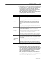
2.
Design the scanner system.
Each application must be evaluated carefully. Successful bar code scanning begins with quality bar
code symbols and the correct number, type, and location of readers, decoders, and package sensors.
Refer to the following when designing your scanner system.
•
•
•
•
Before setting up the system, calculate the expected number of scans per symbol. Make sure
the reader can view the number of scans it needs. If necessary, adjust the symbol speed and/or
the distance between bar-coded packages.
Position the reader at a distance from the symbol that is within the range specified. A read rate
test should be made to verify the range, and also to ensure optimum scanning and decoding.
Avoid aiming the reader perpendicular to the symbol, to avoid directly reflected laser light.
If a package sensor is used, position it so it can sense the package before the symbol reaches
the scan area.
Note: Make sure that the scan beam does not hit the sensor’s reflector; the resulting glare can blind
the reader temporarily.
Publication 2755-6.9
Reference
Chapter 3
(Designing Your
Scanner System)
Introduction to AtomScan+ Bar Code Readers
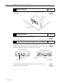
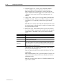
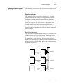
3.
Install the reader.
1–3
Reference
Mount the reader (Catalog Nos. 2755-LS7-SA, 2755-LS7-SB, 2755-LS7-RA, 2755-LS7-RB,
2755-LS7-SBV, or 2755-LS7-RBV) to the mounting plate (Catalog No. 2755-LS7-N) or directly to your
mounting surface. [The maximum distance from the reader to another device is 3 ft. (0.91 m)]. Use
# 6 screws with maximum penetration of 0.15 in. (3.81 mm). If you are not using the mounting plate,
go to step #4.
Chapter 4
(Installing Your
Hardware)
Reader
Mounting Plate
Mount the plate to your mounting surface. You can mount the plate to the top, bottom, or side of your
mounting surface. Use # 6 screws.
Make sure placement of the mounting plate will allow you to connect the reader to the interface box
(Catalog Nos. 2755-LS7-IB1 or 2755-LS7-IB2) or other network device. The maximum distance from
the interface box to the reader is 3 ft. (0.91 m). Skip steps #4 and #5 if you are not using an interface
box.
Reader
Mounting Surface
Publication 2755-6.9
1–4
Introduction to AtomScan+ Bar Code Readers
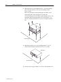
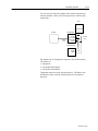
4.
Install the interface box.
Reference
Mount the interface box to your mounting surface. Use # 6 screws with maximum penetration of
0.25 in. (6.35 mm).
Chapter 4
(Installing Your
Hardware)
Interface Box
Mounting Surface
5.
Install the power supply.
Reference
Place the power supply within 6 ft. (1.83 m) of the interface box.
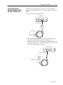
6.
Chapter 4
(Installing Your
Hardware)
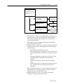
Connect the hardware components together.
Reference
Chapter 4
(Installing Your
Hardware)
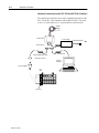
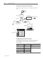
If you are using an interface box, connect the reader, power supply, package detect, and host or
configuration terminal to the interface box. If you are not using an interface box, connect the reader to
the host device, power supply, and any input or output device via a custom cable.
Front View of Interface Box
Scanner Port
Rear View of Interface Box
Power Port
RS-232 Port
Trigger Connector
For information regarding installing the reader for use with an auxiliary monitor or in a daisy-chain
configuration, refer to chapter 4 of this manual.
Publication 2755-6.9
RS-485/422 Port
Chapter 4
(Installing Your
Hardware)
Introduction to AtomScan+ Bar Code Readers
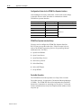
7.
Apply power to the scanner system.
1–5
Reference
After all of your hardware components are installed, apply power to your scanner system. Push the
power button in on the interface box.
Chapter 4
(Installing Your
Hardware)
Front View of the Interface Box
Power Switch
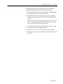
8.
Check the reader defaults.
Check the following configuration parameters on your host device. (Make sure you have a
Windowst terminal utility software on your personal computer.) Make sure the defaults match the
settings listed below. If the defaults do not match, communication between the reader and host
device will not occur.
•
•
•
•
Reference
Chapter 5
(Configuring Your
Reader)
baud rate = 9600
parity = even
stop bits = one
data bits = 7
Read a test bar code to verify that the default settings are correct (i.e., the reader is communicating
with the configuration device).
Publication 2755-6.9
1–6
Introduction to AtomScan+ Bar Code Readers
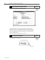
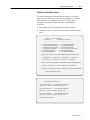
9.
Change the appropriate configuration settings.
Reference
Press [<D>] to access the Main menu. The Main menu appears:
Chapter 5
(Configuring Your
Reader)
From the Main menu you are able to access the configuration settings and change the settings
needed for your application. Use the designated keys to scroll to and select the parameter you wish
to change. Press space bar key (SP) or [N] to scroll ahead, [B] to scroll back, carriage return key
(CR) to select, and [M] to return to the previous higher level menu. To return to the Main menu at
any time, press [ESC] and [M].
If you need to set the reader to the default settings, refer to chapter 6.
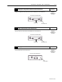
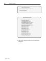
10.
Turn off power to the interface box.
Reference
Push the power button in on the interface box.
Chapter 4
(Installing Your
Hardware)
Front View of the Interface Box
Power Switch
Publication 2755-6.9
Introduction to AtomScan+ Bar Code Readers
11.
Unplug the configuration terminal from the interface box.
1–7
Reference
Unplug the configuration terminal from the RS-232 or RS-485/422 port on the interface box.
Chapter 4
(Installing Your
Hardware)
Rear View of the Interface Box
RS-232 Port
12.
RS-485/422 Port
Plug in the host device to the interface box.
Reference
Plug in the host device to the RS-232 or RS-485/422 port on the interface box.
Chapter 4
(Installing Your
Hardware)
Rear View of the Interface Box
RS-232 Port
13.
RS-485/422 Port
Reapply power to the interface box.
Reference
Push the power button in on the interface box.
Chapter 4
(Installing Your
Hardware)
Front View of the Interface Box
Power Switch
Publication 2755-6.9
Chapter
2
Hardware Features
This chapter describes the features of the AtomScan+ Bar Code
Readers (Catalog Nos. 2755-LS7-SA, 2755-LS7-SB, 2755-LS7-RA,
2755-LS7-RB, 2755-LS7-SBV, and 2755-LS7-RBV) and interface
boxes (Catalog Nos. 2755-LS7-IB1 and 2755-LS7-IB2). Included
are descriptions of:
• reader features
• reader LEDs
• interface box features
• decoding
• safety information
• scan beam options
• accessories
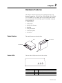
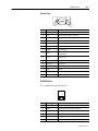
Reader Features
The reader features are shown below.
LEDs
Scan Window
Scan Window
LEDs
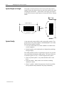
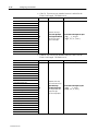
Reader LEDs
There are three LEDs on the back of the readers.
GD/RD RDY PWR
LED
When
Indicates
GD/RD (Good Read)
Green
Good quality label.
RDY (Ready)
Green
Reader is ready to read a label.
PWR (Power)
Red
The reader has power.
Publication 2755-6.9
2–2
Hardware Features
Interface Box Features
The interface boxes route signals between the readers and other
devices. The interface boxes have the following switches and
connectors.
• Auto-load switch. Allows you to load a new match code by
pressing the switch when the reader is scanning a bar code.
• Trigger connector. Connects the interface box to a package
detector such as a PHOTOSWITCHR photoelectric sensor
(Catalog Nos. 42GRP-9000, 42GRU-9000, 42GRU-9200,
42GRC-9000, or 42GRR-9000). Contact your local
Allen-Bradley sales office or distributor for more information
regarding PHOTOSWITCH photoelectric sensors.
• Scanner port. Connects the interface box to the reader cable.
• Default switch. Allows you to restore factory configuration
settings to the reader.
• Power switch. Provides power to the interface box and anything
connected to to the interface box.
• Power port. Allows you to connect the power supply to the
interface box.
• Mode switch. Allows you to toggle the 2755-LS7-IB1 host
communications between RS-232 and RS-485 communications.
• RS-232 port. Connects the interface box to equipment with an
RS-232 port.
• RS-485/422 port. Connects the interface box to equipment with
an RS-485 port (Catalog No. 2755-LS7-IB1) or RS-422 (Catalog
No. 2755-LS7-IB2).
Front View
Auto-Load Switch
Scanner Port
Trigger Connector
Power Switch
Default Switch
Rear View
Power Port
RS-232 Port
Mode Switch
Publication 2755-6.9
RS-485/422 Port
Hardware Features
Decoding
2–3
The readers can decode the following symbologies:
• UPC-A
• UPC-E
• EAN 8
• EAN 13
• Code 39
• Code 128
• EAN 128
• Codabar
• Interleaved 2 of 5
Refer to chapter 5 for more information on the code types listed
above.
Publication 2755-6.9
2–4
Hardware Features
Safety Information
This equipment has been tested and found to comply with the limits
for a Class B digital device, pursuant to Part 15 of the FCC Rules.
These limits are designed to provide reasonable protection against
harmful interference when the equipment is operated in a
commercial environment. This equipment generates, uses, and can
radiate radio frequency energy and, if not installed and used in
accordance with this user manual, may cause harmful interference to
radio communications. Operation of this equipment in a residential
area is likely to cause harmful interference in which case the user
will be required to correct the interference at his or her own expense.
!
!
!
ATTENTION: Use of controls, adjustments, or
performance of procedures other than those specified
herein may result in hazardous laser light radiation
exposure.
ATTENTION: There are no user serviceable parts in
the readers. Opening the scan head could expose the
user to laser diode power of up to 5 mW.
ATTENTION: The laser beam can be harmful to
eyesight. Avoid direct eye contact with the laser beam
Never point the beam at other people, or in a direction
where people may be passing.
Be aware of the following laser caution symbol on the readers.
Publication 2755-6.9
Hardware Features
Scan Beam Options
2–5
Scan beams are projected either as a single line or as a raster pattern.
• The single line option projects its ten scan lines per rotation so
they follow the same path, and appear to be a single scan line.
• The raster option deflects its ten scan lines up and down through
2 degrees of arc during each rotation.
Straight Line
Raster
The raster type reader is useful for reading dot matrix print bar code
symbols.
Accessories
The following accessories are available. Contact your local
Allen-Bradley sales office or distributor for more information
regarding product availability and pricing.
Description
Catalog Number
Straight ahead high density read, single line bar code reader
2755-LS7-SA
Straight ahead low density read, single line bar code reader
2755-LS7-SB
Straight ahead high density read, raster pattern bar code reader
2755-LS7-RA
Straight ahead low density read, raster pattern bar code reader
2755-LS7-RB
Right angle low density read, single line bar code reader
2755-LS7-SBV
Right angle low density read, raster pattern bar code reader
2755-LS7-RBV
Interface box with RS-232 and RS-485 communication
2755-LS7-IB1
Interface box with RS-232 and RS-422 communication
2755-LS7-IB2
Power supply (120V ac, 60 Hz)
2755-LS7-PW1
Mounting plate
2755-LS7-N1
Publication 2755-6.9
Chapter
3
Designing Your Scanner System
This chapter provides the information needed to set up a scanner
system correctly. Items include:
• setup goals
• symbol height and length
• symbol quality
• symbol orientation
• tilt, pitch, and skew
• determining read range
• calculating the number of scans
Setup Goals
Each application must be evaluated carefully. Successful bar code
scanning begins with quality bar code symbols and the correct
number, type, and location of readers, decoders, and package
sensors. Refer to the following when designing your scanner system.
• Before setting up the system, calculate the expected number of
scans per symbol. Make sure the application has the number of
scans it needs. If necessary, adjust the symbol speed and/or the
distance between bar-coded packages.
• Position the reader at a distance from the symbol that is within
the range specified. A read rate test should be made to verify the
range, and also to ensure optimum scanning and decoding.
• Avoid aiming the reader perpendicular to the symbol, to avoid
directly reflected laser light.
• If a package sensor is used, position it so it can sense the package
before the symbol reaches the scan area.
Note: Make sure that the scan beam does not hit the sensor’s
reflector; the resulting glare can blind the reader temporarily.
Publication 2755-6.9
3–2
Designing Your Scanner System
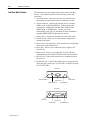
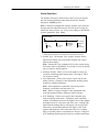
Symbol Height and Length
The height is measured from one end of a bar to the other, and its
length is always the distance from one end of the symbol to the other,
including the Quiet Zones. A Quiet Zone is the empty space before
or after the bars, and is usually equal to 10 times the Narrow Element
Width.
H
Symbol Length = L
Symbol
Height = H
Quiet
Zones
Quiet Zones
Symbol Quality
A bar code reader cannot reliably read a poor quality symbol. Test
proposed bar code symbol samples to ANSI Standard X3.182-1990,
Bar Code Print Quality Guideline.
• Low-cost verifiers that can test this standard are available from
several companies.
• Symbol samples can be submitted to an independent symbology
testing company.
The ANSI guideline specifies six parametric tests plus two pass/fail
tests to determine the printed symbol quality. The tests result in an
overall letter grade of A, B, C, or FAIL assigned to the symbol.
• Grade A printed symbols. Any reader should be able to read
them.
• Grade B symbols. Many readers can read them, including
AtomScan+ readers.
• Grade C symbols. Symbols may appear to decode successfully,
but in production the performance may drop substantially.
Publication 2755-6.9
L
Designing Your Scanner System
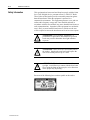
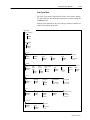
Symbol Orientation
3–3
Bar code symbols must be in the correct position as they move by
the reader. The scan line must cross every bar, space, and both quiet
zones on the same sweep.
Correct:
All bars are
crossed by
scan line
Not Correct:
Some bars are not
crossed by scan
line
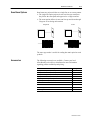
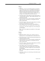
Picket Fence and Step Ladder Orientation
The primary orientation of the bar code symbol can be either picket
fence or step ladder. The orientation is not determined by the
horizontal or vertical position of the symbol itself but rather by the
direction of travel of the bar code past the reader. With picket fence,
the bars are perpendicular to the direction of travel and with step
ladder, the bars are parallel to the direction of travel.
Direction of Travel
Picket Fence
Step Ladder
Publication 2755-6.9
3–4
Designing Your Scanner System
Picket Fence
In picket fence orientation, the symbol can be read the whole time it
is in the read range, rather than being limited by the height of the bar
code. However, picket fence allows scanning of only a small part of
the whole symbol. Slight imperfections such as extraneous ink or
voids can cause misreads or non-reads. The quality of data in picket
fence orientation can be improved by any of the following.
• Make sure the printing on the symbol is of good quality.
• Tilt the scan line slightly to allow a larger part of the symbol to be
scanned as it passes through the scan line.
Reader
Direction
of Travel
Direction
of Travel
Reader
Step Ladder
In general, step ladder orientation is preferred over picket fence
orientation because each scan covers a slightly different part of the
symbol. This means that:
• imperfections in the symbol are less liable to prevent a successful
read, and
• symbol placement is not as critical.
Reader
Direction of
Travel
Publication 2755-6.9
Reader
Direction of
Travel
Designing Your Scanner System
3–5
When to Use a Raster Reader
Single line readers should always used in step ladder orientation.
Raster readers are beneficial in picket fence applications with
symbols printed by a dot matrix printer, where the bars have ragged
edges or voids, or where the spaces have specks in them.
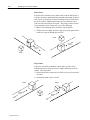
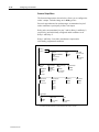
Tilt, Pitch, and Skew
The AtomScan+ reader might read a symbol correctly even if the
symbol or package is not correctly oriented. Refer to the figure
below for various package orientations. Tilt, pitch, and skew can
affect the reader’s ability to read bar code symbols.
Pitched Package
and Symbol
Skewed Package
and Symbol
Tilted Symbol
Correctly Positioned
Symbol and Package
Reader
Tilt
A symbol is tilted when the symbol’s bars are not 90° to the scan
line. The symbol can be read with any tilt, provided the scan line
passes through all bars and quiet zones on each sweep for the
required minimum number of scans. Tilt may reduce the number of
scans in a given application.
Pitch
A symbol is pitched when the symbol’s bars are at different distances
from the reader. From the reader’s perspective, a pitched symbol
appears to have a smaller narrow element width than it actually has.
This may reduce both the read rate and the read range. However, the
symbol can still be read if the apparent narrow element width is
within the reader’s specifications.
Note: Like skew, pitch may be used deliberately to reduce specular
reflection, as long as the application still has the number of scans per
symbol it needs.
Publication 2755-6.9
3–6
Designing Your Scanner System
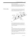
Skew
A symbol is skewed when the ends of the symbol’s bars are not at
the same distance from the reader. The symbol can be read if the
distance of both ends of the bar are within the reader’s read range,
and the skew is less than 40 degrees from the centerline. Unlike
pitch, skew does not affect the read range.
Note: Some skew is necessary to prevent strong reflected light
(specular reflection) from interfering with a successful read. A skew
between 20°-30° is ideal. Or skew may be combined with pitch to
give the following angle.
20_-30_
Reader between 20_ and
30_above or below the symbol
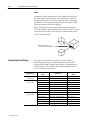
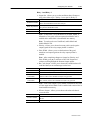
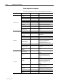
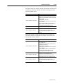
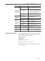
Determining Read Range
The readers can read bar code symbols at various distances
depending upon the type of reader and the narrowest bar code
element width (width of smallest bar or space). With picket fence
orientated labels, scan width is a factor in determining the time it
takes to read a bar code symbol.
Catalog Number
2755-LS7-SA,
2755-LS7-RA
2755-LS7-SB,
2755-LS7-RB
2755-LS7-SBV,
2755-LS7-RBV
Publication 2755-6.9
20_-30_
Minimum Bar Code
Width
5.0 mils (0.13 mm)
7.5 mils (0.19 mm)
7.5 mils (0.19 mm)
10 mils (0.25 mm)
15 mils (0.38 mm)
20 mils (0.51 mm)
30 mils (0.76 mm)
40 mils (1.02 mm)
7.5 mils (0.19 mm)
10 mils (0.25 mm)
15 mils (0.38 mm)
20 mils (0.51 mm)
30 mils (0.76 mm)
40 mils (1.02 mm)
Read Range
2.0 to 3.1 in. (5.08 to 7.87 cm)
2.0 to 4.0 in. (5.08 to 10.2 cm)
2.5 to 5.5 in. (6.35 to 14.0 cm)
2.0 to 6.5 in. (5.08 to 16.5 cm)
2.0 to 7.5 in. (5.08 to 19.0 cm)
2.0 to 10.0 in. (5.08 to 25.4 cm)
2.0 to 10.0 in. (5.08 to 25.4 cm)
2.0 to 10.0 in. (5.08 to 25.4 cm)
1.25 to 4.0 in. (3.18 to 10.2 cm)
1.0 to 5.0 in. (2.54 to 12.7 cm)
1.0 to 6.0 in. (2.54 to 15.2 cm)
1.0 to 8.5 in. (2.54 to 21.6 cm)
1.0 to 8.5 in. (2.54 to 21.6 cm)
1.0 to 8.5 in. (2.54 to 21.6 cm)
Maximum Scan
Width
2.1 in. (5.33 cm)
3.6 in. (9.14 cm)
4.0 in. (10.2 cm)
5.0 in. (12.7 cm)
6.0 in. (15.2 cm)
7.0 in. (17.8 cm)
7.0 in. (17.8 cm)
7.0 in. (17.8 cm)
4.0 in. (10.2 cm)
5.0 in. (12.7 cm)
6.0 in. (15.2 cm)
7.0 in. (17.8 cm)
7.0 in. (17.8 cm)
7.0 in. (17.8 cm)
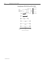
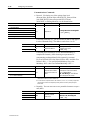
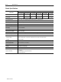
Designing Your Scanner System
3–7
Catalog Numbers 2755-LS7-SA and 2755-LS7-RA
4 in. (10.2 cm)
Scan Width
Reader
2 in. (5.08 cm)
0
2 in. (5.08 cm)
4 in. (10.2 cm)
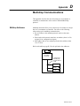
5.0 mils
(0.13 mm)
7.5 mils
(0.19 mm)
0
inches
centimeters
1
2.54
2
5.08
3
7.62
4
10.2
Distance From Front of Reader
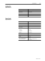
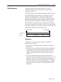
Catalog Numbers 2755-LS7-SB and 2755-LS7-RB
8 in. (20.32 cm)
Scan Width
Reader
4 in. (10.2 cm)
0
4 in. (10.2 cm)
8 in. (20.32 cm)
7.5 mils
(0.19 mm)
10 mils
(0.25 mm)
15 mils
(0.38 mm)
20 mils
(0.51 mm)
30 mils
(0.76 mm)
40 mils
(1.02 mm)
0
inches
centimeters
5
12.7
10
25.4
Distance From Front of Reader
Publication 2755-6.9
3–8
Designing Your Scanner System
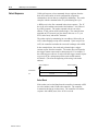
Catalog Numbers 2755-LS7-SBV and 2755-LS7-RBV
8 in. (20.32 cm)
Scan Width
Reader
10 mils
(0.25 mm)
15 mils
(0.38 mm)
20 mils
(0.51 mm)
30 mils
(0.76 mm)
40 mils
(1.02 mm)
0
5
12.7
Distance From Front of Reader
Publication 2755-6.9
0
4 in. (10.2 cm)
8 in. (20.32 cm)
7.5 mils
(0.19 mm)
inches
centimeters
4 in. (10.2 cm)
10
25.4
Designing Your Scanner System
Calculating the Number of
Scans
3–9
To ensure a successful read of a bar code symbol, the bar code
symbol should be scanned 5 times. With fewer scans there will be
more No Read counts, even when the symbol is good. If the symbol
quality is poor, more scans per symbol may also be required.
If the number of scans you derive from one of the following
calculations is less than the minimum for your application, put in the
minimum number of scans and solve for another parameter that
might be changed, such as label speed or scans per second.
Step ladder orientation gives a different number of scans than picket
fence orientation, depending on symbol height, symbol width, and
scan width.
Step Ladder Calculation
To calculate scans per symbol for step ladder applications, use the
following formula.
S =
S
R
H
C
➀
=
=
=
=
RxH
C
–3
➀
Scans per Symbol (should be greater than 5)
Scan Rate
Symbol Height (length of bars of the symbol)
Conveyor Speed
The –3 accounts for the incomplete scans at the beginning and end and one for the Automatic
Gain Adjustment.
Conveyor speed and symbol height must be expressed in similar
units. The calculation assumes that the reader is triggered for the
entire time the symbol is present and the symbol has a 0° pitch.
Step Ladder Example
A bar code symbol is 1 inch tall. The conveyor speed is 10 inches
per second. The scan rate is 500 scans per second. Substitute in the
following values to determine the number of scans the bar code
symbol will receive.
R = 500 scans/second
H = 1 inch
C = 10 inches/second
500 x 1
10
– 3
=
47 scans
Publication 2755-6.9
3–10
Designing Your Scanner System
Picket Fence Calculation
To calculate scans per symbol for picket fence applications, use the
following formula.
S =
S =
R=
W=
L =
C=
➀
R (W–L)
C
–3
➀
Scans per Label
Scan Rate
Scan Width at the Minimum Read Distance
Symbol Length (including quiet zones)
Conveyor Speed
The –3 accounts for the incomplete scans at the beginning and end and one for the Automatic
Gain Adjustment.
Scan width, symbol length, and conveyor speed must be expressed in
similar units. The calculation assumes that the reader is triggered for
the entire time the symbol is present and the symbol has a 0° pitch.
Picket Fence Example
A bar code symbol is 2 inches long. The conveyor speed is 10
inches per second. The scan rate is 500 scans per second. The scan
width is 8 inches. Substitute in the following values to determine the
number of scans the bar code symbol will receive.
R = 500 scans/second
W = 8 inches
L = 2 inches
C = 10 inches/second
500(8 – 2)
10
Publication 2755-6.9
– 3
= 297 scans
Chapter
4
Installing Your Hardware
This chapter provides the information needed to install the readers
and interface boxes. Items include:
• installing the system hardware
• connecting system hardware together when using an interface box
• connecting system hardware together when using an auxiliary
monitor
• connecting system hardware together when using a daisy-chain
configuration
• connecting system hardware together when not using an interface
box
Publication 2755-6.9
4–2
Installing Your Hardware
Installing the System
Hardware
Refer to the following steps to install your system hardware properly.
1. Make sure your scanner system is planned out properly. Refer to
chapter 3 for information regarding planning your scanner
system.
2. Mount the reader (Catalog Nos. 2755-LS7-SA, 2755-LS7-SB,
2755-LS7-RA, 2755-LS7-RB, 2755-LS7-SBV, or
2755-LS7-RBV) to the mounting plate (Catalog No.
2755-LS7-N) or directly to your mounting surface.
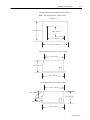
The dimensions of the reader are shown on the next page. The
dimensions of the mounting plate are shown below.
The maximum distance from the reader to another device is 3 ft.
(0.91 m). Use # 6 screws with maximum penetration of 0.15 in.
(3.81 mm). If you are not using the mounting plate, go to step #4.
Reader
Mounting Plate
Note: The drawing below is not to scale.
2.60 in. (6.62 cm)
2.08 in. (5.30 cm)
2.58 in. (6.57 cm)
1.26 in. (3.21 cm)
2.39 in. (6.08 cm)
3.85 in. (9.77 cm)
4.35 in. (11.04 cm)
Publication 2755-6.9
Installing Your Hardware
4–3
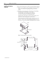
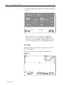
The dimensions of the readers are shown below.
Note: The drawing below is not to scale.
Bottom View
2.59 in. (6.58 cm)
1.36 in. (3.49 cm)
2.5 in. (6.35 cm)
3.47 in. (8.81 cm)
Side View (Catalog Nos. 2755-LS7-SA, -SB, -RA, and -RB)
2.25 in. (5.72 cm)
1.32 in. (3.35 cm)
2.59 in. (6.58 cm)
Side View (Catalog Nos. 2755-LS7-SBV and -RBV)
2.25 in. (5.72 cm)
0.74 in. (1.88 cm)
1.32 in. (3.35 cm)
0.65 in. (1.65 cm)
2.59 in. (6.58 cm)
Publication 2755-6.9
4–4
Installing Your Hardware
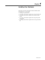
3. Mount the plate to your mounting surface. You can mount the
plate to the top, bottom, or side of your mounting surface.
Use # 6 screws.
Make sure placement of the mounting plate will allow you to
connect the reader to the interface box (Catalog Nos.
2755-LS7-IB1 and 2755-LS7-IB2) or other network device. The
maximum distance from the interface box to the reader is 3 ft.
(0.91 m). Skip steps #4 and #5 if you are not using an interface
box.
Reader
Mounting Surface
4. Mount the interface box to your mounting surface. Use # 6
screws with maximum penetration of 0.25 in. (6.35 mm).
Interface Box
Mounting Surface
5. Place the power supply within 6 ft. (1.83 m) of the interface box.
Publication 2755-6.9
Installing Your Hardware
Connecting System
Hardware Together When
Using an Interface Box
4–5
Follow the steps starting below to connect your system hardware
together when using an interface box. Refer to appendix B for cable
pinouts.
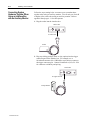
1. Plug the reader into the interface box.
Interface Box
To Scanner Port
Reader
2. Plug any sinking package detect or relay options to the trigger
connector port on the interface box. For example, use a
Switchcraft connector (No. 12BL6M) or equivalent to connect to
the trigger connector port. Contact Switchcraft at (312) 631–1234
for connector availability and pricing.
Interface Box
To Trigger Connector
Package Detector
Publication 2755-6.9
4–6
Installing Your Hardware
To wire the Switchcraft connector, refer to the following table.
Contact your local Allen-Bradley sales office or distributor for
more information regarding PHOTOSWITCH photoelectric
sensors.
Switchcraft Connector Pin
Function of Connection
PHOTOSWITCH Wire Color
One
Trigger from switch
Black (Output)
Four
+12V dc from interface box
Brown
Five
Ground
Blue
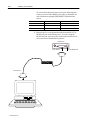
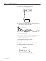
3. Plug host device or configuration terminal into the RS-232 or
RS-485/422 port on the interface box. If you are using the
RS-485/422 port, press the mode switch on the interface box to
access the correct communication protocol.
Interface Box
To RS-232 Port
To Host Device
Publication 2755-6.9
To RS-485/422 Port
Installing Your Hardware
4–7
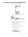
4. Plug the power supply into the interface box.
Interface Box
To Power Port
Power Supply
5. Connect the power supply cable to the power supply and to the
power receptacle supplying 100-240V ac.
To Power Receptacle
To Power Supply
Grounding Pin
6. Turn on the interface box.
If you are using a configuration terminal, you can now perform the
configuration sequence. Refer to chapter 5 for the reader
configuration sequence information.
After performing the configuration sequence:
1. Turn off power to the reader.
2. Unplug the configuration terminal from the interface box.
3. Connect the interface box to the host device.
4. Turn on the interface box.
Interface Box
Power Switch
Publication 2755-6.9
4–8
Installing Your Hardware
Connecting System
Hardware Together When
Using an Interface Box
with an Auxiliary Monitor
Follow the steps starting below to connect your system hardware
together when using an auxiliary monitor. You can only use Series B
or higher of the reader when using an auxiliary monitor. Refer to
appendix B and page 6–11 for cable pinouts.
1. Plug the reader into the interface box.
Interface Box
To Scanner Port
Reader
2. Plug any sinking package detect or relay options into the trigger
connector port on the interface box. For example, use a
Switchcraft connector (No. 12BL6M) or equivalent to connect to
the trigger connector port. Contact Switchcraft at (312) 631–1234
for connector availability and pricing.
Interface Box
To Trigger Connector
Package Detector
Publication 2755-6.9
Installing Your Hardware
4–9
To wire the Switchcraft connector, refer to the following table.
Contact your local Allen-Bradley sales office or distributor for
more information regarding PHOTOSWITCH photoelectric
sensors.
Switchcraft Connector Pin
Function of Connection
PHOTOSWITCH Wire Color
One
Trigger from switch
Black (Output)
Four
+12V dc from interface box
Brown
Five
Ground
Blue
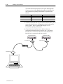
3. Construct a cable that has three 25-pin connectors and will allow
you to connect the host device or configuration terminal, interface
box, and auxiliary port together. Refer to appendix B and
page 6–11 for information regarding cable pinouts.
4. Connect the interface box to host device or configuration terminal
and auxiliary port.
Interface Box
To RS-232 Port
To Host Device
To Auxiliary
Monitor
Publication 2755-6.9
4–10
Installing Your Hardware
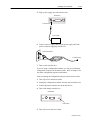
5. Plug the power supply into the interface box.
Interface Box
To Power Port
Power Supply
6. Connect the power supply cable to the power supply and to the
power receptacle supplying 100-240V ac.
To Power Receptacle
To Power Supply
Grounding Pin
7. Turn on the interface box.
If you are using a configuration terminal, you can now perform the
configuration sequence. Refer to chapter 5 for the reader
configuration sequence information.
After performing the configuration sequence:
1. Turn off power to the reader.
2. Unplug the configuration terminal from the interface box.
3. Connect the interface box to the host device.
4. Turn on the interface box.
Interface Box
Power Switch
Publication 2755-6.9
Installing Your Hardware
Connecting System
Hardware Together When
Using an Interface Box in a
Daisy-Chain Configuration
4–11
Follow the steps starting below to connect your system hardware
together when using an interface box. You can only use Series B or
higher of the reader when using the daisy-chain configuration except
for the last reader used in the chain. Refer to appendix B and page
6–9 for cable pinouts.
1. Plug each reader into a separate interface box.
Interface Box
To Scanner Port
Reader
2. Plug any sinking package detect or relay options to the trigger
connector port on each of the interface boxes. For example, use a
Switchcraft connector (No. 12BL6M) or equivalent to connect to
the trigger connector port. Contact Switchcraft at (312) 631–1234
for connector availability and pricing.
Interface Box
To Trigger Connector
Package Detector
Publication 2755-6.9
4–12
Installing Your Hardware
To wire the Switchcraft connector, refer to the following table.
Contact your local Allen-Bradley sales office or distributor for
more information regarding PHOTOSWITCH photoelectric
sensors.
Switchcraft Connector Pin
Function of Connection
PHOTOSWITCH Wire Color
One
Trigger from switch
Black (Output)
Four
+12V dc from interface box
Brown
Five
Ground
Blue
3. Construct a cable that has 25-pin connectors and will allow you to
connect the host device or configuration terminal and interface
boxes together. Refer to appendix B and page 6–9 for
information regarding cable pinouts.
4. Connect the master interface box to the host device or
configuration terminal and slave interface box. (The master
interface box is connected to the master reader and the slave
interface box is connected to the slave reader.)
Master Interface Box
To RS-232 Port
To Host Device
Publication 2755-6.9
Slave Interface Box
To RS-232 Port
Installing Your Hardware
4–13
5. Plug a power supply into each interface box.
Interface Box
To Power Port
Power Supply
6. Connect a power supply cable to each power supply and to the
power receptacle supplying 100-240V ac.
To Power Receptacle
To Power Supply
Grounding Pin
7. Turn on each interface box.
If you are using a configuration terminal, you can now perform the
configuration sequence for the master reader. Refer to chapter 5 for
the reader configuration sequence information.
After performing the configuration sequence on the master reader:
1. Turn off power to the master reader.
2. Unplug the configuration terminal from the master interface box.
3. Connect the master interface box to the host device.
4. Turn on the master interface box.
Interface Box
Power Switch
5. Turn off power to the slave reader.
Publication 2755-6.9
4–14
Installing Your Hardware
6. Disconnect the slave interface box from the master interface box.
7. Connect the configuration terminal to the slave interface box.
8. Turn on the slave interface box.
9. Configure the slave reader. Refer to chapter 5 for the reader
configuration sequence information.
10. Turn off power to the slave reader.
11. Unplug the configuration terminal from the slave interface box.
12. Connect the slave interface box to the master interface box.
13. Turn on the slave interface box.
Publication 2755-6.9
Installing Your Hardware
Connecting System
Hardware Together When
Not Using an Interface Box
4–15
Follow the steps below to connect your system hardware together
when not using an interface box.
1. Determine which pins on the reader cable connector are needed.
Refer to appendix B for a listing of the connector pins of the
reader cable.
2. Construct a mating cable that attaches to the reader cable on one
end and to the other devices on the other end, used in the
application. These devices include:
• RS-232 host device
• 5 V, 500 mA power supply
• package detect sensor
• new master input
• default configuration input
• devices connected to the reader which uses the TTL relay
outputs
3. Plug the reader into the mating cable.
4. Plug the mating cable into the host device, power supply, and
other devices as required by the application.
Publication 2755-6.9
Chapter
5
Configuring Your Reader
This chapter describes the configuration options for the readers.
Items include:
• menu configuration
• serial configuration
• decode test
• adjusting reader parameters
Menu Configuration
You can change the reader’s configuration through the use of menus.
Follow the steps starting below to change the reader’s configuration.
To Access the Reader Configuration Main Menu
1. Make sure you have a terminal utility software running on your
configuration device.
2. Check the following communication port parameters on your
configuration device. Make sure the parameters match the
settings listed below. If the parameters do not match,
communication between the reader and configuration device will
not occur.
Description
Default Setting
Baud Rate
9600
Parity
Even
Stop Bits
One
Data Bits
7
3. Read a test bar code to verify that the default settings are correct
(i.e., the reader is communicating with the host device. The bar
code value will appear on the screen.). If you cannot read a test
bar code:
• verify that you are using the correct communication cable or
• default the reader directly or via the interface box. Refer to
chapter 6 for information regarding defaulting the readers.
Also refer to chapter 7 for information regarding troubleshooting
the readers.
Publication 2755-6.9
5–2
Configuring Your Reader
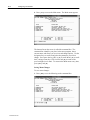
4. Press [<D>] to access the Main menu. The Main menu appears:
The bottom line on the screen is called the command line. The
command line identifies your place in the menu program, shows
current status, and allows you to review and change options. Use the
designated keys to scroll to and select the parameter you wish to
change. Press space bar key (SP) or [N] to scroll ahead, [B] to scroll
back, carriage return key (CR) to select, and [M] to return to the
previous higher level menu. To return to the Main menu at any time,
press [ESC] and [M].
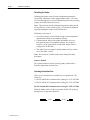
Saving Menu Changes
To save menu changes:
1. Press [ESC] to see the following on the command line.
Publication 2755-6.9
Configuring Your Reader
5–3
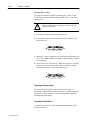
2. Press [M] to return to the Main menu, or press [E] to exit the
Menu Configuration program. If [E] is pressed, the following
screen will appear.
3. Press [N] to exit without saving changes, or press [Y] to retain
the current settings for power-on. If [Y] is selected, a second
beep will indicate the save has been carried out.
Note: Unlike most configuration settings, Scanner Type, Scans per
Second, and Gain Adjustment are not saved for power-on (but are
initialized) when you press [Y]. To save new settings to NOVRAM
for these parameters, press [<ZP>].
Losing Communication
Making changes to communications parameters such as Baud Rate,
Parity, Stop Bits, LRC, etc. without corresponding changes in linked
device(s), can result in the loss of menu access. If this loss occurs,
default the reader with the <Zd> Restore/Save Default Configuration
for Power-on command.
Note: Defaulting the reader will reset all configuration parameters
to their original default values except Scanner Type, Scans per
Second, and Gain Adjustment. Power must be available to the
reader during the default procedure.
Publication 2755-6.9
5–4
Configuring Your Reader
Defining Special Characters
To define any control character from the ASCII table, press the space
bar once. Then enter the control character by holding down the
control key and simultaneously pressing the desired character. For
example, to define a line feed, press the space bar and then
[Control] and [J] simultaneously. The result is displayed as ^J on
the command line and as <LF> in the menu when the screen is
refreshed.
To define CR as a character, press the space bar, then [Control]. It
is displayed as ^M on the command line and as <CR> in the menu
when the screen is refreshed.
To define a space as a character, press the space bar twice. It is
displayed as a blank space in the menu when the screen is refreshed.
While it appears that nothing has been assigned, the hex value 20
will be sent during data transmission.
To select NUL as a character, press the space bar, then a [0] (zero).
It is displayed as <NUL> in the menu when the screen is refreshed.
Publication 2755-6.9
Configuring Your Reader
5–5
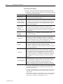
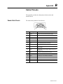
Communications Menu
The Communications menu allows you to set the communication
protocols between the reader and the host device.
Note: Changes in communications parameters or assigning an
address to the reader can cause loss of communications with the
configuration terminal when you exit the menu program (whether or
not changes are saved for power-on).
The Communications menu is shown below. Default settings are in
bold type face.
Communications
Host Protocol
Protocol
Preamble
Preamble
–
Point-to-Point
–
Point-to-Point
–
w/RTS/CTS
Point-to-Point
w/XON/XOFF
Point-to-Point
w/RTS/CTS & XON/XOFF
Polling Mode D
Multidrop
– Address = 1
– User Definable
User Defined
– Req
– EOT
– STX
– ETX
– ACK
– NAK
–
RES
Address = ^A
User Defined Multidrop
RES
Address = ^A
– Req
– EOT
– STX
– ETX
– ACK
– NAK
–
–
–
–
–
–
–
–
–
–
LRC
–
–
–
Disabled
Enabled
–
–
–
–
^M ^J
User Definable
(ASCII char.)
Postamble
–
–
Enabled
Disabled
Interchar Delay
Response Timeout
Disabled
Enabled
–
^M
User
Definable
(ASCII char.)
Postamble
–
12 ms
User Definable
(0 to 65,000)
–
0
User Definable (0 to 255)
Host Port
Baud Rate
–
–
–
–
–
9600
19.2K
38.4K
76.8K
300
Stop Bits
Parity
– 600
–
– 1200
–
– 2400
–
Even
Odd
None
–
–
One
Two
Data Bits
–
–
Seven
Eight
– 4800
Aux Port➀
Mode
–
–
–
–
–
Baud Rate
Disabled
Transparent
Half-duplex
Full-duplex
Slave Mode
➀
–
–
–
–
–
9600
19.2K
38.4K
76.8K
300
Parity
– 600
–
– 1200
–
– 2400
–
Even
Odd
None
Stop Bits
–
–
One
Two
Data Bits
–
–
Seven
Eight
– 4800
The auxiliary port is available through the interface box (Catalog Nos. 2755-LS7-IB2 or -IB2).
Publication 2755-6.9
5–6
Configuring Your Reader
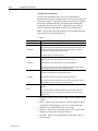
Host Protocol Parameters
• Protocol. Protocols define the sequence and format in which
information is transferred between devices. The protocol options
are listed in the following table.
Parameter
Description
Point-to-Point
Has no address and sends data to the host (RS-232) whenever it is available and
without any request or handshake from the host.
Point-to-Point with
RTS/CTS (Request-toSend/Clear-to-Send)
Used only with RS-232. This is a simple handshaking protocol that allows a device
to initiate data transfers to the host with an RTS (request-to-send) transmission. The
host, when ready, responds with a CTS (clear-to-send) and the data is transmitted.
CTS and RTS signals are transmitted over two dedicated wires (pins 6 and 10) as
defined in the RS-232 standard.
Point-to-Point with
XON/XOFF
(Transmitter On/Off)
Used only with RS-232. This selection enables the host to send a single byte
transmission command of start (XON) or stop (XOFF). If an XOFF has been
received from the host, data will not be sent to the host until the host sends an XON.
During the XOFF phase, the host is free to carry on other chores and accept data
from other devices.
Point-to-Point with
RTS/CTS &
XON/XOFF
Used only with RS-232. It is a combination of Point-to-Point with RTS/CTS and
Point-to-Point with XON/XOFF.
Polling Mode D
Like Point-to-Point, Polling Mode D requires a separate connection to the host; but
unlike Point-to-Point, it requires an address and must wait for a poll from the host
before sending data. When in Polling Mode D, an address of 1 is automatically
displayed on the configuration screen. However, during transmission, a 1C hex poll
address (FS) and a 1D hex select address (GS) are substituted for the 1.
Multidrop➀
Similar to Polling Mode D except that a unique poll address and select address are
required for each multidrop device, and only one host port connection is needed for
up to 50 devices. Requires a concentrator or controller using RS-485
communications. When Multidrop is selected, the protocol characters for RES, REQ,
etc. are assigned automatically.
User Defined
Used only with RS-232. ASCII characters can be assigned as an address and as
protocol commands (RES, REQ, EOT, STX, ETX, ACK, and NAK). User Defined is
necessary when a new protocol must be defined to match a specific host protocol.
When User Defined is selected, the displayed protocol commands match those of
the previously selected protocol. User Defined is considered to be in a polled mode
only if an address has been assigned. The address can be any ASCII character
except NUL➁.
User Defined Multidrop
Used when connecting to a concentrator or other device that does not match
standard Multidrop protocol. Any single character (01 hex to 7E hex) in the ASCII
table can be assigned as the address character. The character chosen is used as
the poll character and the subsequent ASCII character becomes the select
character. For example, if a ^A (01 hex) is selected as the address, ^B (02 hex)
becomes the select address that the host will use in sending host select commands.
➀
Once the reader is configured for Multidrop, a terminal connected to the auxiliary RS-232 pins or a
default procedure must be used to access the configuration menus again (although serial
commands will continue to function).
➁
For example a simple ACK/NAK protocol can be developed by first selecting Point-to-Point, then
User Defined, and then assigning characters to ACK and NAK commands. First scroll to the
following command:
HOST PROTOCOL --> PROTOCOL --> USER DEFINED--> ACK = --> Press [^F] by holding
down the Control key while pressing the F key, and then press [CR] to see the following:
HOST PROTOCOL --> PROTOCOL --> USER DEFINED --> ACK = ^F
Publication 2755-6.9
Configuring Your Reader
5–7
Note: Definitions of commands in User Defined and User
•
•
•
•
•
•
•
Defined Multidrop must be duplicated in host applications to
enable poll and select sequences to execute correctly during
transmission.
Typically, parameters in User Defined Multidrop are defined by
first enabling Multidrop, then enabling User Defined Multidrop.
This pre-loads Multidrop characters into the parameters. You
then change individual characters to match the host or other
requirements.
Preamble. Allows you to define a one or two character data
string that can be added to the front of the decoded data. For
example, a carriage return and line feed would display each
decoded message on its own line.
Preamble. Allows you to enable or disable the preamble
character(s).
Postamble. Allows you to define a one or two character data
string that can be added after the decoded message.
Postamble. Allows you to enable or disable the Postamble
character(s).
Longitudinal Redundancy Check (LCR). An error-checking
routine that verifies the accuracy of transmissions. It is the
exclusive OR of all characters following the SOM (start of
message) up to and including the EOM (end of message).
Response Timeout. Allows you to set the time the reader will
wait before timing out if ACK, NAK, and ETX are enabled, and a
host response is expected.
Intercharacter Delay. Allows you to set the time interval in
milliseconds between individual characters transmitted from the
reader to the host. A high setting will significantly slow down
communications. For example, a 200 setting will result in a 1/5
second delay between each transmitted character.
Host Port Parameters
• Baud Rate. Allows you to set the number of bits transmitted per
second.
• Parity. Allows you to select an error detection routine in which
one data bit in each character is set to 1 or 0 so that the total
number of 1 bits in the data field is even or odd.
• Stop Bits. Allows you to select the last one or two bits in each
character to indicate the end of the character.
• Data Bits. Allows you to establish the total number of bits in
each character.
Publication 2755-6.9
5–8
Configuring Your Reader
Auxiliary Port Parameters
Auxiliary Port Parameters allow you to set communications
parameters between daisy-chained readers or between the reader and
an auxiliary monitor. An auxiliary monitor can be used to configure
the menus, send data to the host, and display data transmissions
originating from the host or reader. The auxiliary port cannot be
used in conjunction with RS-485 or RTS/CTS on the host port.
Note: The Aux Port baud rate should never exceed Host Port baud
rate or auxiliary port data could be lost.
• Mode.
Parameter
Disabled
Transparent
Description
Data is not sent to the auxiliary monitor.
Used to batch data from the auxiliary monitor to the host. The decoder buffers data
from the auxiliary monitor and displays the keyed data on the auxiliary monitor. The
decoder transmits auxiliary monitor data to the host when a label is scanned or a
carriage return is entered from the auxiliary monitor.
Transparent mode can work with all protocols.
Operates exactly like Full-duplex except that the bar code data is displayed on the
auxiliary monitor screen at the same time the data is sent to the host.
Half-duplex
Half-duplex mode can work with all protocols except polled protocols.
The auxiliary characters are echoed to the host without the optional inter-character
delay and without checking for the optional XON/XOFF status.
All the auxiliary monitor data and bar code data is sent directly to the host. The bar
code data is not displayed on the auxiliary monitor screen.
Full-duplex
Full-duplex mode can work with all protocols except polled protocols.
The auxiliary characters are echoed to the host without the optional inter-character
delay and without checking for the optional XON/XOFF status.
Allows a reader connected to the auxiliary port to input data replacing the no read
message.
Slave
In a daisy-chain setup, Slave Mode is enabled in the master reader and all slave
readers except the last one in line because the last one in line does not use the
auxiliary port pins.
• Baud Rate. Allows you to set the number of bits transmitted per
second.
• Parity. Allows you to select an error detection routine in which
one data bit in each character is set to 1 or 0 so that the total
number of 1 bits in the data field is even or odd.
• Stop Bits. Allows you to select the last one or two bits in each
character to indicate the end of the character.
• Data Bits. Allows you to establish the total number of bits in
each character.
Publication 2755-6.9
Configuring Your Reader
5–9
Operations Menu
The Operations menu, shown below, allows you to set the operations
parameters for the reader. Default settings are in bold type face.
Operations
Triggering Mode
–
–
–
–
–
–
Trigger Filter➁
–
–
78
2 to 255
Good Decode
Reads
–
–
Multilabel
Separator
–
–
, (comma)
any ASCII
character
1
1 to 31
Match Code
Type
–
–
–
–
Match Start
Position
–
–
Timeout in 10 ms Serial Trigger
Character
End of
incs➀
Read Cycle
Read
Continuous Read 1 – Timeout
– 100
Output
– 0 to 65,535
– New Trigger
External Level
– Timeout & New
External Edge
Trigger
Serial Data
Serial Data & Edge
0
0 to 64
Disabled
Enabled
Sequential
Wild Card
Match Length
–
–
1
1 to 64
–
–
^]
any ASCII
character
New Master
Pin
–
–
Disabled
Enabled
Match Code
Master
–
–
External
Trigger
Level
(blank)
User entry (up
to 64
characters)
–
–
Positive
Negative
Number of
Labels
–
–
1
1 to 6
Sequential
Matching
–
–
Increment
Decrement
Wild Card Character
–
–
* (asterisk)
any ASCII character
➀
Divide the number entered on the command line by 100 for time in seconds.
➁
Multiply the number entered on the command line by 128 for time in microseconds, then divide by
1000 for time in milliseconds.
Publication 2755-6.9
5–10
Configuring Your Reader
• Triggering Mode. Allows you to establish the type of trigger
event that will initiate or end the read cycle. The trigger event
options are listed in the following table.
Parameter
Description
Trigger input options are disabled and the reader is always in the read cycle. Bar
code data is decoded, and label information is transmitted repeatedly, as long as the
label is in the read range of the reader. When To Output options have no affect on
Continuous Read. Continuous Read is useful in testing label or reader functions.
Continuous Read
If both Continuous Read and Match Code are enabled the reader defaults to
Continuous Read, 1 Output mode.
Label data is immediately transmitted once every time new label data is placed in
front of the reader. With Timeout enabled for End Of Read Cycle, if the label doesn’t
change, the reader will repeat the output at the end of each subsequent timeout
period. For example, if Timeout were set to one second, the reader would output the
label data immediately, and then repeat the output at intervals of one second, for as
long as the label continued to be scanned.
Continuous Read, 1
Output
With Timeout disabled (that is, End Of Read Cycle set to New Trigger), the reader
will output the current label data immediately, but output it only once. A new label
appearing at any time in the scan range will produce a new read output as long as
the new label is not identical to the previous label.
Enabling Continuous Read, 1 Output when Number of Labels is set to any number
greater than one will cause Number of Labels to default back to one.
External Level
Allows a read cycle to be initiated by a trigger signal from a package detector when a
package appears within the detector’s range. The read cycle exists as long as the
detector “sees” the package and ends when the package moves out of the detector’s
range➀.
External Edge
As with Level, Edge allows a read cycle to be initiated by a trigger signal from a
package detector when it detects the appearance of a package (rising edge). But
unlike Level mode, the removal of a package (falling edge) does not end the read
cycle. With Edge enabled, the read cycle ends with a good read output, a timeout,
or a new trigger.
Serial Data
The reader accepts an ASCII character from the host or controlling device as a
trigger to start a read cycle. Serial data trigger behaves the same as External Edge.
Serial Data and
External Edge
The reader accepts either an external trigger or a serial ASCII command to start a
read cycle.
➀
Publication 2755-6.9
Level and Edge apply to the active logic state (positive or negative) that exists while the package
is in a read cycle, between the rising edge and falling edge. Rising edge is the trigger signal
associated with the appearance of a package. Falling edge is the trigger signal associated with
the subsequent disappearance of the package.
Configuring Your Reader
5–11
• End of Read Cycle. Allows you to choose the circumstances that
will end the read cycle. The read cycle is the time during which
the reader will receive and process label data. When the
Triggering Mode option is set in an External or Serial mode of
operation, the trigger event initiates the read cycle.
Note: When operating in Continuous Read or Continuous Read,
1 Output, the reader is always in the read cycle.
The End of Read Cycle options are listed in the following table.
Parameter
Description
Can end the read cycle after a specified period of time, and if no label has been
read, causes a no read message, if enabled, to be transmitted.
With either External Edge, Serial Data, or Serial Data & Edge enabled, a timeout
ends the read cycle.
Timeout
With External Level enabled, the read cycle does not end until the falling edge
trigger occurs, and the next read cycle does not begin until the next rising edge
trigger.
With Continuous Read, 1 Output enabled, a timeout initiates a new read cycle and
allows the same label to be read again.
Ends the read cycle at the occurrence of a new trigger event, and if no label has
been read, causes a no read message, if enabled, to be transmitted at the
occurrence of the new trigger event.
New Trigger
With either External Edge, Serial Data, or Serial Data & Edge enabled, an edge or
serial trigger ends a read cycle and initiates the next read cycle.
With External Level enabled, a falling edge trigger ends a read cycle. However, the
next read cycle does not begin until the occurrence of the next rising edge trigger.
Ends the read cycle after a specified period of time or at the occurrence of new
trigger event, and if no label has been read, causes a no read message, if enabled,
to be transmitted.
Timeout and New
Trigger
With either External Edge, Serial Data, or Serial Data & Edge enabled, a timeout, or
an edge or serial trigger, whichever comes first, ends the read cycle.
With External Level enabled, the read cycle does not end until the occurrence of a
falling edge, and the next read cycle does not begin until the next rising edge trigger.
• Timeout. Allows you to define the duration of the timeout period
in 10 millisecond increments.
• Serial Trigger Character. Allows you to define a single ASCII
character as the host serial trigger character that initiates the read
cycle. The serial trigger is considered an on-line host command
and requires the same command format as all host commands
(that is, to be entered within the < > brackets).
Note: Serial Data or Serial Data & Edge must be enabled for
Serial Trigger Character to take effect. “N/A” is displayed in the
menu when all other triggering modes are enabled.
Publication 2755-6.9
5–12
Configuring Your Reader
• External Trigger Level. Allows you to determine whether a
positive or negative transition will initiate the read cycle.
Note: External Level, External Edge, or Serial Data & Edge
must be enabled for External Trigger Level to take effect. “N/A”
is displayed in the menu when all other triggering modes are
enabled.
• Trigger Filter. Allows you to set a trigger bounce filter duration.
• Good Decode Reads. Allows you to select the number of good
reads (from 1 to 31) required per label before a good decode
output.
Note: Be sure to set the value within the determined scan rate for
the scanning setup so that the reader is capable of scanning a label
the required number of times.
• Match Code Type. When enabled, allows you to enter a master
label into the reader’s memory to be compared with subsequently
scanned labels. The Match Code Types are listed in the table
below.
Selecting
Causes
Disabled
no effect on reader operation.
Enabled
the reader to compare labels or portions of labels with the master label.
Sequential
the reader to compare labels or portions of labels for sequential numbers in
ascending or descending order.
Wild Card
you to enter user defined wild card characters in the master label. For example, you
have a ten digit label of which only the first six digits “URGENT” need to match. You
can enter URGENT**** as your master label, assuming of course that the wild card is
currently defined as the default asterisk (*).
With Match Code Type enabled, a master label can be entered
three ways as shown on page 5–13.
Note: A triggered mode must be enabled for Match Code Type
to take effect.
Note: Enabling Match Code Type when Number of Labels is set
to any number greater than one will cause Number of Labels to
default back to one.
Note: If you wish to send a pulse on a Good Read, Match Code
Type must be disabled.
Publication 2755-6.9
Configuring Your Reader
5–13
Enable Match Code Type:
By menu selection,
by operational command <E>, or,
by serial configuration command
<Kn1>.
Enable New Master Pin:
By menu selection, or
by serial configuration
command <Kz1>.
Enter the next label scanned as the
master label by operational
command <G>.
Download a new master label
directly into memory by operational
command <)XXXX)>.
Toggle reader pin 12 to GND (pin 4) to
enter next label scanned as the master
label. Grounding can also be
accomplished by pressing the New
Master switch on the interface box.
Read in the
master label.
Compare the master label
with subsequent labels
• New Master Pin. Allows you to momentarily connect pin 12 to
ground in order to clear any existing master label information
from memory and allows the next label to be read as the new
master label information.
Note: Match Code and a triggered mode must be enabled for
New Master Pin to take effect.
• Number of Labels. Allows you to choose the number of different
labels that will be read in a single trigger event. The following
conditions apply.
– Each label must be different to be read.
– The maximum number of characters in any one label is 64.
– The maximum number of characters in a single scan line is
384.
– The maximum number of characters for all labels is 384,
including preamble, postamble, and all spaces and
commas.
– All no read messages are posted at the end of the data
string.
– If more than one label is within the scan beam at the same
time, label data may not be displayed in the order of
appearance.
Note: If Number of Labels is set to any number greater than one
while Match Code or Continuous Read, 1 Output is enabled,
Number of Labels will default back to one.
• Multilabel Separator. Allows you to choose the separator
character to be inserted between each label.
Publication 2755-6.9
5–14
Configuring Your Reader
• Match Code Master. Allows you to edit an existing master or
•
•
•
•
type in a new master label from your keyboard. You can display
current master and accept entry up to 64 characters.
Sequential Matching. Defines the order (ascending or
descending) in which labels will be compared when Match Code
Type is set to Sequential.
Match Start Position. Defines the first character in the label
(from left to right) that will be compared with those of the master
label when Match Code Type is set to Enabled or Sequential. For
example, if you set Match Start Position to 3, the first 2
characters read in the label will be ignored and only the 3rd and
subsequent characters to the right will be compared, up to the
number of characters specified by Match Length. Match Start
Position must be set to one or greater to enable this feature.
Match Length. Defines the length of the character string that will
be compared with that of the master label when Match Code Type
is set to Enabled or Sequential and Match Start position is set to 1
or greater. For example, If Match Length is set to 6 in a 10
character label, and Match Start Position is set for 2, only the 2nd
through 7th characters (from left to right) will be compared.
Wild Card Character. Allows you to define the Wild Card
Character that can be used when defining a Master Label. A
Master label can be entered 4 different ways.
– By typing in from the keyboard at the command line of the
Operations menu under Match Code Master.
– With New Master Pin enabled, toggling reader pin 12 to
ground (or by momentarily pressing the New Master
button on the interface box) will save the next label read as
the master label.
– Pressing [<G>] allows the next label read to be the master
label.
– Sending a serial command in the format <)XXXX)>
downloads data as the master label.
Publication 2755-6.9
Configuring Your Reader
5–15
Code Types Menu
The Code Types menu, shown below, allows you to choose among
five bar code types and define their parameters. Default settings are
in bold type face.
Options can be defined for any bar code type whether or not the bar
code itself is enabled at the time.
Code Types
Narrow Margins
Status
–
–
Disabled
Enabled
Symbology ID
Status
–
–
Disabled
Enabled
Code 39
Status
–
–
Check Digit
Enabled
Disabled
–
–
Check Digit
Output
Disabled
Enabled
–
–
Disabled
Enabled
Large Interchar
Gap
–
–
Fixed Code
Length
Disabled
Enabled
–
–
Code Length
–
Disabled
Enabled
–
10
User Definable
(1 to 31)
Codabar
Status
–
–
Disabled
Enabled
Start
& Stop
Match
–
–
Start
& Stop
Output
Enabled
Disabled
–
–
Fixed Code
Length
Large Interchar
Gap
–
Enabled
Disabled
–
Disabled
Enabled
–
–
Disabled
Enabled
Code Length
–
–
10
User
Definable
(1 to 31)
Check Digit
–
–
–
–
Disabled
Modulus 16
NW7
Both
Check Digit
Output
–
–
Disabled
Enabled
I 2 of 5
Status
Disabled
Enabled
–
–
Check Digit
–
–
Disabled
Enabled
Check Digit
Output
–
–
Disabled
Enabled
Code Length #1
–
–
10
User Definable
(even, 0 to 30)
Code Length #2
–
–
6
User Definable
(even, 0 to 30)
UPC
Status
–
–
Disabled
Enabled
EAN
–
–
Disabled
Enabled
Supplementals
Disabled
Enabled
Required
–
–
–
Separator
–
–
Disabled
Enabled
Separator (character)
–
–
, (comma)
User Definable
(ASCII char.)
Code 128
Status
–
–
Disabled
Enabled
Fixed Code
Length
–
–
Disabled
Enabled
Code Length
–
–
10
User Definable
(1 to 31)
Publication 2755-6.9
5–16
Configuring Your Reader
Narrow Margins
Allows the reader to read bar codes with quiet zones less than 10
times the narrow-bar-width. Quiet zone is a term used to describe
the minimum space at the leading and trailing ends of a label. Each
quiet zone can be as small as five times the narrow bar element when
Narrow Margins is enabled.
Symbology ID
The symbology ID is a string of 3 characters prefixed to label data
messages. The first character is ]. The ] symbol is used whenever
the option is enabled. The second character indicates the label type.
Refer to the first table below for the label types. The third character
is the sum of the applicable option values per symbology used.
For example, you have code 39 with no character check and data is
1234. When symbology ID is disabled, the result is 1234. When the
symbology ID is enabled, the result is ]A01234.
Label Type Indicator
Equals
A
Code 39
F
Codabar
I
I 2 of 5
E
UPC/EAN
C
Code 128
Code 39 Option Value
No check character.
1
Reader has checked the check character.
2
Reader has removed the check character.
Codabar Option Value
Option Definition
0
No check character.
2
Reader has checked the check character.
4
Reader has removed the check character.
I 2 of 5 Option Value
Option Definition
0
No check character.
1
Reader has checked the check character.
2
Reader has removed the check character.
UPC/EAN Option Value
0
0
Option Definition
Always zero and does not follow the AIM spec.
Code 128 Option Value
Publication 2755-6.9
Option Definition
0
Option Definition
Always zero and does not follow the AIM spec.
Configuring Your Reader
5–17
Code 39
• Status
• Check Digit. Code 39 is self-checking and does not normally
•
•
•
•
require a check digit. However, for additional data integrity, a
Modulus 43 check digit can be added to the bar code message.
With Check Digit and an External or Serial Trigger option
enabled, an invalid check digit calculation will cause a no read
message to be transmitted at the end of the read cycle.
Check Digit Output. When enabled, the check digit character is
sent along with the label data. When disabled, label data is sent
without the check digit.
Large Intercharacter Gap. Allows the reader to read labels with
gaps between bar code characters exceeding three times the
narrow element width.
Fixed Code Length. Used to increase data integrity by ensuring
that only one label length will be accepted.
Code Length. Allows you to specify the exact number of
characters that the reader will recognize (this does not include
start and stop). The reader will ignore any code not having the
specified length.
Note: Fixed Code Length must be enabled for Code Length to
take effect.
Codabar
• Status
• Start and Stop Match. Requires the Codabar start and stop
•
•
•
•
•
characters (a, b, c, or d) to match before a valid read can occur.
Start and Stop Output. Allows the start and stop characters to be
transmitted with bar code data.
Large Intercharacter Gap. Allows the reader to read labels with
gaps between bar code characters exceeding three times the
narrow element width.
Fixed Code Length. Used to increase data integrity by ensuring
that only one label length will be accepted.
Code Length. Allows you to specify the exact number of
characters that the reader will recognize (this does not include
start and stop). The reader will ignore any code not having the
specified length.
Note: Fixed Code Length must be enabled for Code Length to
take effect.
Check Digit. Allows you to select the type of checksum system
Codabar will use.
Publication 2755-6.9
5–18
Configuring Your Reader
• Check Digit Output. When enabled, the check digit character is
sent along with the label data. When disabled, label data is sent
without the check digit.
I 2 of 5
• Status. Because I 2 of 5 is a continuous code, it is prone to
•
•
•
•
substitution errors. Therefore, a code length must be defined and
a bar code label containing an even number of digits must be
used. It is also recommended that a Modulus 10 check digit be
used to ensure the best possible data integrity.
Check Digit. I 2 of 5 uses a Modulus 10 check digit.
Check Digit Output. When enabled, the check digit character is
sent along with the label data. When disabled, label data is sent
without the check digit.
Code Length #1. With I 2 of 5, two code lengths can be defined.
When using only one label length in an application, set Code
Length #2 to 0 to ensure data integrity. If a check digit is used, it
must be included in the code length count.
Code Length #2. If using a second label, you may also specify a
zero or any even code length from 2 to 30. If you are not using a
second label, set Code Length #2 to 0 to ensure data integrity.
UPC
• Status. When enabled, the reader will read UPC version A and
UPC version E only.
• EAN. When EAN is enabled, the reader will read UPC version
A, UPC version E, EAN 13, and EAN 8. It will also append a
leading zero to UPC version A label information and transmit 13
digits. If you do not want to transmit 13 digits when reading
UPC version A labels, disable EAN.
Note: UPC must be enabled for EAN to take effect.
• Supplementals. Allows the reader to read supplemental bar code
data that has been appended to the standard UPC or EAN codes.
When set to Required, the reader treats the supplemental data and
the bar code label as a single label. Also, supplemental data must
be found or a no read will result. When set to Enabled, the reader
treats the supplemental data and the bar code label as separate
labels.
Note: If Supplementals is set to Enabled, Number of Labels must
be set to two (for each label used) and Triggering Mode must not
be set to Continuous Read, 1 Output. For example, if you are
using one (UPC) label and Supplementals is Enabled, set Number
of Labels to 2 (but if you are using two labels under the same
conditions, set Number of Labels to 4).
• Separator. Allows you to insert a character between the standard
UPC or EAN code and the supplemental code.
Publication 2755-6.9
Configuring Your Reader
5–19
• Separator (Character). Allows you to change the separator
character from a comma to a new value.
Code 128
• Status
• Fixed Code Length. Allows you to increase data integrity by
ensuring that only one label length will be accepted.
• Code Length. Allows you to specify the exact number of
characters that the reader will recognize. The reader will ignore
any code not having the specified length.
Note: Fixed Code Length must be enabled for Code Length to
take effect.
Publication 2755-6.9
5–20
Configuring Your Reader
Scanner Output Menu
The Scanner Output menu, shown below, allows you to configure the
reader’s output. Default settings are in bold type face.
Bar code output data and no read messages are transmitted on pin 2
under conditions set principally in Bar Code Output.
Relay pulses are transmitted via pins 7 and 14 (Relay-1 and Relay-2,
respectively) and individually configured under conditions set in
Relay-1 and Relay-2.
Relay-1 and Relay-2 can allow simultaneous output under
individually programmed conditions.
Scanner Output
Relay-1
Relay-2
Output On
–
–
–
–
Bar Code
Output
–
–
–
–
Good Read
Disabled
Match
Mismatch
–
As Soon As
Possible
End Of Read
Cycle
Beeper Status
–
–
Mismatch or No Read
Match
(or Good Read)
Mismatch
No Read
When to Output
–
Polarity
–
–
–
No Read
User Definable
(ASCII char.)
Beeper Volume
On Good
On No Read
–
–
–
–
–
–
–
–
No Read Message
7 digits
–
Negative
Positive
Pulse Width
(in 10 ms incs)➀
No Read Output
–
–
Enabled
Disabled
Full Screens
Level 4
Level 5
Off
Level 1
Level 2
Level 3
–
–
Enabled
Disabled
Laser On/Off
–
–
Partial Output
Status
–
–
➀
Publication 2755-6.9
Disabled
Enabled
Start Position
–
–
1
User Definable
(1 to 63)
Length
–
–
50 ms
User Definable
(0 to 255)
63
User Definable
(1 to 63)
Divide the number entered on the command line by 100 for time in seconds.
Disabled
Enabled
Configuring Your Reader
5–21
Relay–1 and Relay–2
• Output On. Allows you to set the conditions that will output a
relay pulse either to pin 7 (Relay-1) or to pin 14 (Relay-2).
Parameter
Description
Mismatch or No Read
Sends a pulse when the label’s data does not match that of the master label or the
label is not decoded before the end of the read cycle.
Match (for good read)
Sends a pulse when the decoded label matches the master label. (To send the pulse
on a good read, disable Match Code.)
Mismatch
Sends a pulse when the label’s data does not match that of the master label.
No Read
Sends a pulse when the label’s data is not decoded before the end of the read cycle.
Note: If Output On is set to Mismatch or No Read, Match, or
Mismatch, a relay pulse will not output unless Match Code is
enabled and a master label is downloaded into memory.
Note: To send a pulse on a Good Read, enable Match and
disable Match Code.
• Polarity. Allows you to choose between positive and negative
output signals for the relay output pin that is enabled.
• Pulse Width. Allows you to set the duration of the good
match/no read output signals at the relay output pin that is
enabled.
Note: After completing changes to Output On, Polarity, and
Pulse Width, press [M] to advance to Bar Code Output and
continue scrolling through the Scanner Output options.
• Bar Code Output. Allows you to choose the conditions that will
send label data (or no read messages) to the host.
Parameter
Description
Good Read
The reader will output on any good read independent of how Match Code is set.
Disabled
The reader will not output label data or no read messages to the serial port.
Match (with Match
Code enabled)
The reader will output when the label data information matches the master label.
However, if Match Code is disabled it will output on any good read.
Mismatch (with Match
Code enabled)
The reader will output when the label data information does not match the master
label. However, if Match Code is disabled it will output on any good read.
Note: If Bar Code Output is set to Match or Mismatch, label data
will not output unless Match Code is enabled and a master label is
downloaded into memory.
• When to Output. Allows you to choose when bar code data is
sent to the host.
Parameter
Description
As soon as Possible
Causes bar code data (good reads) to be transmitted immediately upon a good
decode.
End of Read Cycle
Causes bar code data output to be delayed until the end of the read cycle.
Publication 2755-6.9
5–22
Configuring Your Reader
• No Read Message. Allows you to define any combination of
•
•
•
•
•
ASCII characters (except NUL) up to seven characters as the no
read message. When enabled, the no read message will be
transmitted to the host at a timeout or the end of a read cycle if
the bar code label has not been decoded.
No Read Output. Allows you to enable or disable the no read
message.
Note: If No Read Output is enabled, the no read message will
only output if Bar Code Output is also enabled and MS-sensor
Status is disabled.
Beeper Status. A beep is emitted either after each good read of a
bar code label or after each no read.
Note: The beep period will be short for triggered modes where a
new trigger occurs immediately or the output is delayed to the
end of the read cycle on edge and serial triggers.
Beeper Volume
Full Screens. Allows you to display either the full menu screen
or just the command line. When Full Screens is disabled, only
the command line will be displayed.
Laser On/Off. When enabled, the laser is ON only during the
read cycle. When disabled, the laser operates continuously.
Note: A serial or external trigger must be enabled for Laser
On/Off to take effect.
Note: Laser On/Off does not relate to the <H> (Enable Laser
Scanning) or <I> (Disable Laser Scanning) operational
commands.
Partial Output
• Status. When enabled, allows you to transmit part of the label to
the host.
• Start Position. Allows you to define the starting character of
label information that is sent to the host.
• Length. Allows you to define the number of characters of a label
that are sent to the host.
Publication 2755-6.9
Configuring Your Reader
5–23
Scanner Setup Menu
The Scanner Setup menu, shown below, allows you to set specific
bar code scanning parameters that affect decode rate. Default
settings are in bold type face.
Note: Unlike most configuration settings, Scanner Type, Scans per
Second, and Gain Adjustment are not saved for power-on (but are
initialized) when you press [Y]. To save new settings to NOVRAM
for these parameters, press [<ZP>].
Scanner Setup
Scanner
Type
–
–
➀
Standard
High Density
Scans per Second➀ Gain Adjustment
–
–
50
User Definable
(30 to 55)
–
–
45 (nominal)
User Definable
(10 to 255)
AGC Sampling
–
–
–
Continuous
Disabled
Leading Edge
Multiply the number entered on the command line by 10 for actual scans per second.
• Scanner Type. The Scanner Type “default” from the factory
indicates the density type of the reader (with the unit’s optics
adjusted accordingly).
Note: Entering the <Zp> command will save the current setting
for Scanner Type to NOVRAM. If you need to verify the density
type of a unit, see the FIS options.
• Scans per Second. Allows you to set the number of scans per
second by controlling mirror motor speed. The range is 300 to
550 scans per second.
• Gain Adjustment. Allows you to specify a gain value for the
analog circuitry. Changes to Gain Adjustment should typically
be done by qualified technicians.
Note: Gain Adjustment is optimized at the factory before
shipment; your default value may not be 45.
Note: Before saving any changes to Gain Adjustment, first
record the optimized factory setting for future reference.
• AGC Sampling. Allows you to specify how automatic gain
control sampling will be done. Continuous mode continually
samples 14 transitions and stores the highest value of the samples
and adjusts the AGC value at the end of the scan. Leading Edge
mode finds the leading edge by looking for a 40 ms quiet zone
followed by 14 transitions and stores the highest value of the
samples and adjusts the AGC at the end of the scan. Leading
Edge is especially effective when labels are skewed. Changes to
AGC Sampling should typically be done by qualified technicians.
Publication 2755-6.9
5–24
Configuring Your Reader
Serial Configuration
Most of the configuration changes to the reader that can be made in
the menu can also be accomplished by command strings from the
host.
Serial command strings are entered from an ASCII device. As with
menu configuration commands, serial configuration commands relate
to the initial reader setup.
Serial Configuration Command Format
The format for a serial configuration command is:
<Kparameterdata,data,...etc.><initializing command>
Keep the following in mind when using serial configuration
commands.
• Less than < and greater than > symbols are included as part of the
commands.
• “parameter,” as used here, are those character(s) that precede the
data.
• The “initializing command” <A> or <Z> is sent after
configuration is complete. <Z> resets and saves for power up.
<A> initializes the change to RAM.
• Parameters and data are “case sensitive.” That is, characters must
be entered as upper or lower case, as specified.
• All data fields (except the last) must be followed by a comma
(without a space).
• If there is no change in a given field, then commas can be entered
alone, or with the existing data (for example, <Ka,,,0> or
<Ka4,1,0,0>).
• All fields preceding the modified field must be included. For
example, in Host Port, to change Data Bits to Eight without
changing any other field, press either: [<Ka,,,1>] or
[<Ka4,1,0,1>].
• All fields following the modified field can be left out. For
example, in the RS-232 port, to change Baud Rate to 4800, press
[<Ka3>].
To ensure that a serial configuration command will take affect,
follow it with one of the operational commands below.
• <A> To reset but not save changes for power-on
• <Z> To reset and save changes for power-on
For example, to change Baud Rate and reset without saving changes
for power-up, press [<Ka3><A>].
To change Baud Rate and reset, saving the changes to NOVRAM,
press [<Ka3><Z>].
Publication 2755-6.9
Configuring Your Reader
5–25
To ensure that a command was received and accepted, you can enter
the Show Scanner Status command, <?>.
Concatenating Serial Commands
Commands can be concatenated (added together) to a maximum of
64 characters in a single string or data block. Additional data blocks
of 64 or less characters can be sent provided there is at least a 10 ms
pause between blocks.
For example, <Kc1><Kh1><Ko1><A> enables LRC, sets End of
Read Cycle mode to New Trigger, enables Narrow Margins and
resets the data buffers (without saving the changes for power-on).
Serial Command Status Request
The status of serial commands can be requested by entering the
command followed by a question mark. For example, press [<Ke?>]
to request the Postamble status.
Losing Communications
Making changes to communications parameters such as Baud Rate,
Parity, Stop Bits, LRC, etc. without corresponding changes in linked
device(s) can result in the loss of menu access. If this should occur,
default the reader with the <Zd> Restore/Save Default Configuration
for Power-on command.
Note: Defaulting the reader will reset all standard configuration
parameters except Scanner Type, Scans per Second, and Gain
Adjustment to their original default values.
Note: Power must be available to the reader during the default
procedure.
Publication 2755-6.9
5–26
Configuring Your Reader
Serial Configuration Commands
The table starting below lists the serial configuration commands.
Function
Communications
Command
Communications
Protocol
Preamble
Postamble
LRC
Response Timeout
Intercharacter Delay
Host Port
Auxiliary Port
Communications
Status Request
Triggering Mode
End of Read Cycle
Serial Trigger
Character
External Trigger Level
Good Decode Read
Operations
Parameter
Kf
<Kfprotocol,address>
Kd
Ke
Kc
KA
KB
Ka
<Kdstatus,ASCII characters>
<Kestatus,ASCII characters>
<Kcstatus>
<KAtimeout setting>
<KBnumber>
<Kabaud,parity,stop bits,data bits>
<Kymode,baud rate,parity,stop bits,data
bits>
Ky
KT
<KT?>
Kg
Kh
<Kgmode,filter time>
<Khmode,time>
Ki
<Kicharacter>
Kj
Km
<Kjmode>
<Kmnumber>
<Kntype,sequential matching,match start
position,match length,wild card
character,sequence on no
read,sequence on every mismatch>
<Kzstatus>
<KLnumber of labels,multilabel
separator>
Match Code Type
Kn
New Master Pin
Kz
Number of Labels
KL
Operations Status
Request
KV
Narrow Margins
Ko
Code 39
Kp
Codabar
Kq
I 2 of 5
Kr
UPC/EAN
Ks
Code 128
Code Types Status
Request
Kt
<Konarrow margin status,symbology ID
status>
<Kpstatus,check digit status,check digit
output status,large intercharacter
gap,fixed code length status,code
length>
<Kqstatus,start & stop match status,start
& stop output status,large intercharacter
gap,fixed code length status,code
length,check digit type,check digit
output>
<Krstatus,check digit,check digit
output,length 1,length 2>
<Ksstatus,EAN status,supplementals
status,separator status,separator cha.>
<Ktstatus,fixed length,length>
KW
<KW?>
Code Types
Table continued on the next page.
Publication 2755-6.9
Format
<KV?>
Configuring Your Reader
Function
Scanner Output
Command
Kv
Kw
Kl
Kk
Ku
KC
Serial Verification
KS
Scanner Output Status
Request
Partial Output
Scanner Type
Scans per Second
Auto Gain Control
Scanner Setup
Parameter
Relay 1
Relay 2
Bar Code Output
No Read Message
Beeper
Laser On/Off
Bad Bar Code
Message
No Bar Code Message
No Object Bar Code
Message
Scanner Setup Status
Request
Format
<Kvoutput on,polarity,pulse width>
<Kwoutput on,polarity,pulse width>
<Klstatus,when to output>
<Kkstatus,output>
<Kustatus,volume>
<KCstatus>
<KSserial command status,serial
command beep status,control/hex
output>
KX
<KX?>
KY
KP
KE
<KYstatus,start position,length>
<KPdensity>
<KEspeed>
<KDgain adjustment,AGC
sampling,tracking>
KD
5–27
KM
<KMstatus,message>
KN
<KNstatus,message>
KO
<KOstatus,message>
KU
<KU?>
The sections that follow describe the commands listed in the table
starting on the previous page. The defaults listed in the tables are in
bold type.
Publication 2755-6.9
5–28
Configuring Your Reader
Communications Commands
• Protocol. If selecting one of the options from 0 to 4
(Point-to-Point, Point-to-Point with RTS/CTS, Point-to-Point
with XON/XOFF, Point-to-Point with RTS/CTS and
XON/XOFF, or Polling Mode D), use the format below.
Command
Parameter
Protocol
0 = Point-to-Point
1 = Point-to-Point with RTS/CTS
2 = Point-to-Point with XON/XOFF
3 = Point-to-Point with RTS/CTS and XON/XOFF
4 = Polling Mode D
Kf
Format
<Kfprotocol>
Example
To change the Protocol to Polling Mode
D, press [
[<Kf4>].
]
If selecting Multidrop (5), you must define an address and append
it to the command string. The address can be from 1 to 50.
Command
Parameter
Format
Protocol
Kf
<Kfprotocol,address>
5 = Multidrop
Example
To change the Protocol to Multidrop with
an address of 33, press
[<Kf5,33>].
If selecting User Defined (6) or User Defined Multidrop (7),
complete the format by either choosing new parameters or
concatenating unchanged data fields (separate by commas).
For User Defined, first select Point-to-Point <Kf0> and then User
Defined <Kf6...>. For user Defined Multidrop, first select
Multidrop <Kf5>, then User Defined Multidrop <Kf7...>.
Command
Parameter
Format
Protocol
6 = User Defined
<Kfprotocol,RES,address,
REQ,EOT,STX,ETX,ACK,
NAK>
Kf
7= User Defined Multidrop
Example
To select an unpolled ACK/NAK User
Defined protocol with LRC disabled,
press [<Kf0><Kf6,,,,,,,
^F ^U K 0 ]➀. ACK and NAK
^F,^U><Kc0>]
will be displayed in the menu➁.
➀
<Kf0> nulls the address and <Kc0> disables LRC.
➁
A control character, represented here as two characters (^F or ^U, etc.), is actually a single ASCII
character that is entered on the keyboard by holding down the control key while pressing the
desired letter.
• Preamble. You can enter one or two preamble characters except a
null (00H).
Command
Status
0 = Disabled
1 = Enabled
Publication 2755-6.9
Parameter
Kd
Format
<Kdstatus,preamble
character(s)>
Example
To enable Preamble with just one
character, an FF (form feed), press
[<Kd1,^L>].
Configuring Your Reader
5–29
• Postamble. You can enter one or two postamble characters except
a null (00H).
Command
Status
0 = Disabled
1 = Enabled
Parameter
Ke
Format
<Kestatus,postamble
character(s)>
Example
To disable Postamble, press
[<Ke0>].
[<Ke0>]
• LRC
Command
Status
0 = Disabled
1 = Enabled
Parameter
Kc
Format
<Kcstatus>
Example
To enable LRC, press [<Kc1>].
• Response Timeout. You can use any number from zero to 65,000.
(A zero causes an indefinite wait.) The default is 12 ms.
Parameter
KA
Format
<KAtimeout setting>
Example
To change Response Timeout to 30 ms,
press [<KA30>].
• Intercharacter Delay. You can use any number from zero to 255.
The default is zero.
Parameter
KB
Format
<KAtime interval>
Example
To change Intercharacter Delay to
30 ms, press [<KB30>].
Publication 2755-6.9
5–30
Configuring Your Reader
• Host Port. Changes made in the reader’s communications
parameters such as baud rate, parity, stop bits, LRC, etc., must be
matched in the other device(s) or communications will be lost. If
this occurs, default the reader with the <Zd> Restore/Save
Default Configuration for Power-on command.
Command
Baud Rate
0 = 600
1 = 1200
2 = 2400
3 = 4800
4 = 9600
5 = 19200
6 = 38400
7 = 76800
8 = 300
Parity
0 = None
1 = Even
2 = Odd
Stop Bits
0 = One
1 = Two
Data Bits
0 = Seven
1 = Eight
Publication 2755-6.9
Parameter
Ka
Format
<Kabaud rate,parity,stop
bits,data bits>
Example
To change Host Port Baud Rate to 2400,
press [<Ka2>].
[
]
Configuring Your Reader
5–31
• Auxiliary Port
Command
Mode
0 = Disabled
1 = Transparent
2 = Half-duplex
3 = Full-duplex
4 = Slave Mode
Baud Rate
0 = 600
1 = 1200
2 = 2400
3 = 4800
4 = 9600
5 = 19200
6 = 38400
7 = 76800
8 = 300
Parity
0 = None
1 = Even
2 = Odd
Stop Bits
0 = One
1 = Two
Data Bits
0 = Seven
Parameter
Ky
Format
<Ky mode,baud
rate,parity,stop bits,data
bits>
Example
To change Auxiliary Port Baud Rate to
2400, press [<Ky2>].
[ y ]
1 = Eight
• Communications Status Request. Allows you to return the status
of each command in the group.
Parameter
KT
Format
<KT?>
Operations Commands
• Triggering Mode. The trigger filtering time occurs in 128
microsecond increments. You can use any number between 2 and
255. The default is 78 (approximately 10 seconds).
Command
Triggering Mode
0 = Continuous Read
1 = Continuous Read, 1 Output
2 = External Level
3 = External Edge
4 = Serial Data
5 = Serial Data and Edge
Parameter
Kg
Format
<Kgtriggering mode,filter
time>
Example
To select External edge, press
[<Kg3>].
[<Kg3>]
Publication 2755-6.9
5–32
Configuring Your Reader
• End of Read Cycle. The timeout occurs in 10 millisecond
increments. You can use any number between zero and 65535.
The default is 100 (one second).
Command
Parameter
End of Read Cycle Mode
0 = Timeout
1 = New Trigger
Kh
Format
<Khend of read cycle
mode,timeout>
Example
To select Timeout and change the
timeout value to 6 seconds, press
[<Kh0 600>]
[<Kh0,600>].
2 = Timeout and New Trigger
• Serial Trigger Character. You can use any available ASCII
character. The default character is ^. Pressing [<^>] when using
the default character with the serial triggering mode selected, will
trigger the reader.
Parameter
Ki
Format
Example
<Kiserial trigger character>
To define the Serial Trigger Character as
a lower case c, press [<Kic>].
• External Trigger Level
Command
External Trigger Level
0 = Negative
1 = Positive
Parameter
Kj
Format
<Kjexternal trigger level>
Example
To change External Trigger Level to
negative, press [<Kj0>]
[<Kj0>].
• Good Decode Reads. You can use any number between 1 and 31.
The default is 1.
Parameter
Km
Format
<Kmnumber of reads>
Example
To change Good Decode Reads to 3,
press [<Km3>].
• Match Code Type
Command
Status
0 = Disabled
1 = Enabled
2 = Sequential
3 = Wild Card
Sequential Matching
0 = Increment
1 = Decrement
Match Start Position
0 to 64. 0 is the
default.
Match Length
1 to 64. 1 is the
default.
Wild Card Character
Any character. *
(asterisk) is the
default.
Publication 2755-6.9
Parameter
Kn
Format
<Kntype,sequential
matching,match start
position,match length,wild
card character,sequence
on no read,sequence on
every mismatch>
Example
To enable Match Code Type for
Sequential, set Sequential Matching for
Decrement, and enable Sequence on
Every Mismatch, press
[<Kn2,1,,,,,1>].
Configuring Your Reader
5–33
For a sequence on a No Read, refer to the following table. When
disabled, the reader does not sequence (increment or decrement)
on a No Read. When enabled, the reader sequences on every No
Read.
Command
Example
Status
0 = Disabled
If 001, 002, No Read, then search for 003.
1 = Enabled
If 001, 002, No Read, then search for 004.
For a sequence on every mismatch, refer to the following table.
When disabled, if a mismatch is out of sequence by more than 1,
the sequence resumes. When enabled, the reader sequences the
on every mismatch.
Command
Example
Status
0 = Disabled
If 001, 002, 004 (mismatch), then search for 005.
1 = Enabled
If 001, 002, mismatch, then search for 004.
• New Master Pin
Command
Status
0 = Disabled
1 = Enabled
Parameter
Kz
Format
<Kzstatus>
Example
To enable New Master Pin, press
[<Kz1>].
[<Kz1>]
• Number of Labels. You can use any number between 1 and 6.
The default is 1. The multilabel separator is any valid ASCII
character.
Parameter
KL
Format
<KLnumber, multilabel
separator>
Example
To change Number of Labels to 3, press
[<KL3>].
• Operations Status Request. Allows you to return the status of
each command in the group.
Parameter
KV
Format
<KV?>
Code Types Commands
• Narrow Margins
Command
Status
0 = Disabled
1 = Enabled
Parameter
Ko
Format
<Konarrow margin
status,symbology ID
status>
Example
To enable Narrow Margins, press
[<Ko1>].
[<Ko1>]
Publication 2755-6.9
5–34
Configuring Your Reader
• Code 39. You can use any number between 1 and 64 for the
Fixed Code Length. The default is 10.
Command
Status
0 = Disabled
1 = Enabled
Check Digit Status
0 = Disabled
1 = Enabled
Check Digit Output Status
0 = Disabled
1 = Enabled
Large Intercharacter Gap
0 = Disabled
1 = Enabled
Fixed Code Length Status
0 = Disabled
Parameter
Kp
Format
<Kpstatus,check digit
status,check digit output
status,large intercharacter
gap,fixed code length
status,code length>
Example
To set Fixed Code Length to 30, press
[<Kp,,,,1,30>] or
[<Kp1,0,0,0,1,30>].
p
1 = Enabled
• Codabar. You can use any number between 1 and 31 for the
Fixed Code Length. The default is 10.
Command
Status
0 = Disabled
1 = Enabled
Start and Stop Match Status
0 = Disabled
1 = Enabled
Start and Stop Output Status
0 = Disabled
1 = Enabled
Large Intercharacter Gap
0 = Disabled
1 = Enabled
Fixed Code Length Status
0 = Disabled
1 = Enabled
Check Digit Output
0 = Disabled
1 = Enabled
Check Digit Type
0 = Disabled
1 = Mod 16
2 = NW7
3 = Both
Publication 2755-6.9
Parameter
Kq
Format
<Kqstatus,start & stop
match status,start & stop
output status,large
intercharacter gap,fixed
code length status,code
length,check digit
type,check digit output>
Example
To set Fixed Code Length to 9, press
[<Kq1,,,,1,9>] or
[<Kq1,1,1,0,1,9>].
q
Configuring Your Reader
5–35
• I 2 of 5. Code length #1 can be zero or any even number from 2
to 64. The default is 10. Code length #2 can be zero or any even
number from 2 to 64. The default is 6.
Command
Status
0 = Disabled
1 = Enabled
Check Digit Status
0 = Disabled
1 = Enabled
Check Digit Output Status
0 = Disabled
Parameter
Kr
Format
Example
<Krstatus,check digit,check
digit output,length 1,
length 2>
To set Fixed Code Length #1 to 8 and #2
to 4, press [<Kr1,,,8,4>] or
[<Kr1,0,0,8,4>].
1 = Enabled
• UPC/EAN. The Separator character can be any ASCII character
except NUL. The default is , .
Command
UPC Status
0 = Disabled
1 = Enabled
EAN Status (UPC must be enabled)
0 = Disabled
1 = Enabled
Supplementals Status
0 = Disabled
1 = Enabled
2 = Required
Separator Status
0 = Disabled
Parameter
Format
<KsUPCstatus,EAN
status,supplementals
status,separator
status,separator cha.>
Ks
Example
To change Supplementals to Required,
and change Separator Character to a
dash (–), press
[<Ks1,1,2,1,–>]
[<Ks1,1,2,1,–>].
1 = Enabled
• Code 128. You can use any number between 1 and 64 for the
Code Length. The default is 10.
Command
Status
0 = Disabled
1 = Enabled
Fixed Code Length Status
0 = Disabled
1 = Enabled
Parameter
Kt
Format
<Ktstatus,fixed
length,length>
Example
To enable Code 128, enable Fixed Code
Length, and set Code Length to 9, press
[<Kt1 1 9>]
[<Kt1,1,9>].
• Code Types Status Request. Allows you to return the status of
each command in the group.
Parameter
KW
Format
<KW?>
Publication 2755-6.9
5–36
Configuring Your Reader
Scanner Output Commands
• Relay–1. The pulse width occurs in 10 millisecond increments.
You can use any number between 2 and 255. The default is 5.
Command
Parameter
Output On
0 = Mismatch or No Read
1 = Match or Good Read
2 = Mismatch
3 = No Read
Polarity
0 = Negative
1 = Positive
Kv
Format
Example
<Kvoutput on,polarity,pulse
width>
To set Relay 1 to Mismatch and change
Pulse Width to 40 ms, press
[<Kv2 0 4>] or [<Kv2,4>].
[<Kv2,0,4>]
[<Kv2 4>]
• Relay–2. The pulse width occurs in 10 millisecond increments.
You can use any number between 2 and 255. The default is 5.
Command
Parameter
Output On
0 = Mismatch or No Read
1 = Match or Good Read
2 = Mismatch
3 = No Read
Polarity
0 = Negative
1 = Positive
Kw
Format
Example
<Kwoutput on,polarity,pulse
width>
To set Relay 2 to Mismatch and change
Pulse Width to 40 ms, press
[<Kw2 0 4>] or [<Kw2,4>].
[<Kw2,0,4>]
[<Kw2 4>]
• Bar Code Output
Command
Parameter
Status
0 = Disabled
1 = Match
2 = Mismatch
3 = Good Read
When to Output
0 = As soon as Possible
1 = End of Read Cycle
KI
Format
<Klstatus,when to output>
Example
To set When to Output to End of Read
Cycle, press [
[<KI3,1>].
, ]
• No Read Message. You can use any ASCII string up to 7
characters in length. The default is No Read.
Command
Status
0 = Disabled
1 = Enabled
Publication 2755-6.9
Parameter
Kk
Format
<Kkstatus,output>
Example
To enable No Read Message and send
the message FAIL, press
[<Kk1,FAIL>].
Configuring Your Reader
5–37
• Beeper
Command
Beeper Status
0 = On Good
1 = On No Read
Beeper Volume
0 = Off
1 = Level 1
2 = Level 2
3 = Level 3
4 = Level 4
5 = Level 5
Parameter
Ku
Format
<Kustatus,volume>
Example
To set the beeper for On No Read and
set the beeper volume to Off, press
[<Ku1 0>]
[<Ku1,0>].
• Laser On/Off
Command
Status
0 = Disabled
1 = Enabled
Parameter
KC
Format
<KCstatus>
Example
To enable Laser On/Off, press
[<KC1>].
[<KC1>]
• Serial Verification
Command
Serial Command Echo Status
0 = Disabled
1 = Enabled
Serial Command Beep Status
0 = Disabled
1 = Enabled
Control/hex Output
0 = Control
1 = Hex
Parameter
KS
Format
<KSserial command
status,serial command
beep status,control/hex
output>
Example
To enable Serial Command Echo Status,
Beep status, and Hex Output, press
[<KS1,1,1>].
• User Output Status Request. Allows you to return the status of
each command in the group.
Parameter
KX
Format
<KX?>
• Partial Label Output. Allows you to transmit a portion of the
label to the host.
Command
Status
0 = Disabled
1 = Enabled
Start Position
1 to 63. 1 is the default.
Length
Parameter
KY
Format
<KYstatus,start
position,length>
Example
To enable Partial Label Output starting
at character 4 and ending at character 8
of the string, press [<KY1,4,5>].
[<KY1 4 5>]
1 to 63. 63 is the default.
Publication 2755-6.9
5–38
Configuring Your Reader
Scanner Setup Commands
• Scanner Type. You determine the type of reader you are using.
Entering the <Zp> command will save the current setting for
Scanner Type to NOVRAM.
Command
Scanner Type
0 = Standard
1 = High Density
Parameter
KP
Format
<KPdensity>
Example
Do not change the reader type.
• Scans per Second. The scan occurs in 10 millisecond increments.
You can use any number between 30 and 55. The default is 50.
Parameter
KE
Format
<KEspeed>
Example
To set the reader to 400 scans per
second, press [<KE40>].
• Auto Gain Control. Gain adjustment can be any number from 10
to 255. The default is 45.
Before saving any changes to Gain Adjustment, first record the
optimized factory setting for future reference. Press [<KU?>] to
read factory settings.
Command
AGC Sampling
0 = Disabled
1 = Leading Edge
2 = Continuous
Parameter
KD
Format
<KDgain adjustment,AGC
sampling,tracking>
Example
To set the gain threshold to 40 and the
AGC status to Leading Edge, press
[<KD40 1 0>]
[<KD40,1,0>].
• Bad Bar Code Message. You can use any ASCII string up to 7
characters. The default is Bad Code.
Command
Status
0 = Disabled
1 = Enabled
Parameter
KM
Format
<KMstatus,message>
Example
To change the message to “FAULTY”,
press [<KM1,FAULTY>].
[<KM1 FAULTY>]
• No Bar Code Message. You can use any ASCII string up to 7
characters. The default is No Label.
Command
Status
0 = Disabled
Parameter
KN
Format
<KNstatus,message>
1 = Enabled
Example
To change the message to “NO LABEL,
press [<KN1,NOCODE>].
[<KN1 NOCODE>]
• No Object Message. You can use any ASCII string up to 7
characters. The default is Missing.
Command
Status
0 = Disabled
1 = Enabled
Publication 2755-6.9
Parameter
KO
Format
<KOstatus,message>
Example
To change the message to “VACANT”,
press [<K01,VACANT>].
[<K01 VACANT>]
Configuring Your Reader
5–39
• Scanner Setup Status Report. Allows you to return the status of
each command in the group.
Parameter
KU
Decode Test
Format
<KU?>
To test the decode rate:
1. Position the label in front of a functioning reader.
2. Press [<C>] from the host terminal to launch the decode rate test.
3. Observe decode rate.
4. Check depth-of-field (minimum/maximum range) by moving the
label closer and further relative to the reader and noting the points
where the decode rates fall below a level acceptable to your
application. The label used in your application should pass
through or near the center of the depth-of-field.
5. Repeat steps 1 through 5 for other labels used in your application
and end the decode rate test by pressing [<J>].
If the decode rate is acceptable, no adjustments are needed to your
reader. If the decode rate is unacceptable, adjust your reader
parameters.
Note: If, after making adjustments, you have changed the read range
or another parameter used in the number of scans formula, you
should recalculate the number of scans.
Note: Variations between labels are common. For this reason, the
greater number of sample labels you test, the more likely you are to
achieve optimum decode rates.
Adjusting Reader
Parameters
To help improve decode rates, adjustments can be made in the
following areas.
Scan Rate
Scan rate is a function of motor speed and is adjustable from 300 to
550 within the Scanner Setup menu. The reader is factory set at the
rate of 500 scans per second. A slower scan rate may allow greater
label range and/or higher decode rates, but at the cost of fewer scans
per label. To adjust the scan rate (motor speed), press [<D>] and
select the Scanner Setup menu.
Publication 2755-6.9
5–40
Configuring Your Reader
Range
Adjusting the label’s range, if possible, is one of the quickest and
most effective ways to improve decode rates. However, in some
applications you may need to select a less than optimum range, or
one that is beyond the fringes of the ranges.
Scan Width
Increasing scan width will increase the number of scans in a picket
fence oriented application. Scan width is linked with scan range and
changing one will usually require a change in the other.
Label Speed
Applies to both picket fence and step ladder oriented labels. If your
application allows it, label speed (the time in seconds that a label is
fully within the scan width of the reader) is an effective way to alter
the number of scans.
Label Dimensions, Label Density, and Label Ratio
Not usually an option in most applications, but changes to label
parameters can affect number-of-scan calculations and possibly
decode rates.
If your application allows it, shortening the length of a picket fence
label means the label will be in the scan range longer and hence
receive a greater number of scans. Increasing the height of a step
ladder label means it will receive more scans. Changing label
density and/or bar code ratio is another way ranges, decode rates, etc.
can be altered.
Gain
This adjustment, typically made by qualified technicians, is done
from within the Scanner Setup menu.
Publication 2755-6.9
Chapter
6
Hardware Operation
This chapter provides information on how to operate your scanner
system hardware. Items include:
• using operational commands
• operating scanner system hardware
Using Operational
Commands
On-line serial operational commands are sent from the host to the
reader to carry out routine operations “on the fly” as distinguished
from serial configuration commands that are generally used in initial
setup.
Operational commands are preceded by a < left angle bracket symbol
and followed by a > right angle bracket symbol. Command start
character by default is a left angle bracket, <. It may be redefined by
menu or serial command. However, the end character, a right angle
bracket, >, cannot be changed.
The table on the next page lists the operational commands.
Publication 2755-6.9
6–2
Hardware Operation
Function
Program Management
Device Control
Code Types
Counter
Test
Status
Command
<A>
<Ad>
<An>
<D>
<Z>
<Zd>
<Zp>
<H>
<I>
<KE>
<KF>
<L1>
<L2>
<P>
<Q>
<R>
<S>
<N>
<O>
<T>
<U>
<V>
<W>
<X>
<Y>
<C>
<Ce>
<J>
<#>
<!>
<?>
<?1>
Master Label
<E>
<F>
<G>
<)XXXX)>
<)>
<))>
➀
Publication 2755-6.9
Action
Software Reset (does not save for power-on)
Software Reset/Restore Default
Software Reset/Read NOVRAM
Enter Configuration Mode
Software Reset/Save Parameters for Power-on
Restore/Save Default Configuration for Power-on
Save Scanner Type, SPS, and Gain for Power-on
Enable Laser Scanning (Laser On)
Disable Laser Scanning (Laser Off)
Motor On
Motor Off
Relay-1 Pulse
Relay-2 Pulse
Autodiscriminate All Codes
Enable Code 39 Only➀
Enable Codabar Only➀
Enable I 2 of 5 Only➀
No Read Counter
No Read Counter Reset
Trigger Counter
Trigger Counter Reset
Match Code/Good Read Counter
Match Code/Good Read Counter Reset
Mismatch Counter
Mismatch Counter Reset
Enter Decode Rate Test
Enter Extended Decode Rate Test
Exit Decode Rate Test; Exit Extended Decode Rate Test
Display Software Part Number
Display Checksum of EPROM
Show Scanner Status
Show Software Status (Send Status Byte, Part Number, and ROM
Checksum. Display NOVRAM Checksum at Power Up, then Display
Current NOVRAM Checksum)
Enable Match Code Option➀
Disable Match Code Option➀
Store Next Label Scanned as Master Label
Download Master Label Information
Request Master Label Information
Delete Master Label Information
The command can also be set in the configuration menu or with a serial configuration command.
Hardware Operation
6–3
Program Management Commands
• Software Reset, [<A>]. Initializes all serial configuration
•
•
•
•
•
•
commands in RAM and resets all counters and operating
parameters.
Note: Software Reset will cause the numeric counters in use to
lose their count; record all data that you wish to save prior to
sending this command.
Software Reset/Restore Default, [<Ad>]. Restores the ROM
default values to RAM then initializes them. Does not effect
Scanner Type, Scans per Second, or Gain Adjustment.
Software Reset/Read NOVRAM, [<An>]. Reads the NOVRAM
settings then initializes them to RAM.
Enter Configuration Mode, [<D>]. Enters the Menu
Configuration Program.
Software Reset/Save Parameters for Power-on, [<Z>]. Allows
you to save all but Scanner Type, Scans per Second, and Gain
Adjustment to NOVRAM. The values of numeric counters are
not saved by this command.
Note: The Software Reset/Save Parameters for Power-on
command can be executed at least 10,000 times. In normal usage
this will exceed the life of the reader. If frequent changes to the
operating parameters are required, it is recommended that the
<Z> command be used only when the current configuration has
been changed and the changes are to be permanent.
Restore/Save Default Configuration for Power-on, [<Zd>].
Allows you to restore and save default settings for all but Scanner
Type, Scans per Second, and Gain Adjustment to NOVRAM.
Note: Power must be available to the reader during the default
procedure.
Defaulting might be necessary after temporary changes or if
communications between the reader and another device are lost or
interrupted, or if you are using incompatible equipment. For
example, a terminal is set to communicate at 9600 baud, but the
reader is configured at 38.4K baud.
Save Scanner Type, SPS, and Gain for Power-on, [<Zp>].
Allows you to save the current settings for Scanner Type, Scans
per Second, and Gain Adjustment to NOVRAM. Once you send
this command, default values can only be recalled if you reenter
them individually and then save them again with this command.
Note: This command will replace the optimized factory setting
for Gain Adjustment with your new setting; record and save this
setting for future reference prior to sending this command.
Publication 2755-6.9
6–4
Hardware Operation
Device Control Commands
• Enable Laser Scanning (Laser On), [<H>].
• Disable Laser Scanning (Laser Off), [<I>]. This feature is useful
•
•
•
•
during extended periods of time when no bar code labels are
being scanned. Disabling laser scanning will not affect any
downloaded commands to the reader.
Motor On, [<KE>]. Turns the motor on (reaches full speed after a
short time delay).
Motor Off, [<KF>]. Turns the motor off.
Relay-1 Pulse, [<L1>]. Allows you to send a pulse to pin 7 (at
any time regardless of Match Code or Relay-1 Driver status).
Relay-2 Pulse, [<L2>]. Allows you to send a pulse to pin 14 (at
any time regardless of Match Code or Relay-2 Driver status).
Code Types Commands
• Autodiscriminate All Codes, [<P>]. Enables the reader to decode
all available bar code types without changing reader
configuration settings.
Note: For maximum scanning speed, enable only those bar code
symbologies used in the application.
• Enable Code 39 Only, [<Q>]. Allows only Code 39 labels to be
read.
• Enable Codabar Only, [<R>]. Allows only Codabar labels to be
read.
• Enable I 2 of 5 Only, [<S>]. Allows only Interleaved 2 of 5
labels to be read.
Counter Commands
The Xs in all counter commands that follow denote a numeric value
from 00000 to 65,535. After reaching the maximum numeric limit
of 65,535, you will receive an error message and the counter will
automatically rollover and start counting again at 00000. To obtain
the cumulative total of counts after the rollover has occurred, add
65,536 per each rollover (the reader does not keep track of the
number of rollovers) to the current count.
Note: You will lose all counter values if you cycle power to the
reader, press [<A>], or enter the Menu Configuration Program.
Publication 2755-6.9
Hardware Operation
6–5
Note: If you activate the counter command during a read cycle, the
reader will not output the count until the read cycle ends.
• No Read Counter, [<N>]. The message N/XXXXX displays the
total number of no reads that have occurred since power-on or the
last No Read Counter Reset command.
• No Read Counter Reset, [<O>]. Sets No Read Counter to 00000.
• Trigger Counter, [<T>]. The message T/XXXXX displays the
total number of triggers since power-on or the last Trigger
Counter Reset command.
• Trigger Counter Reset, [<U>]. Sets the trigger counter to 00000.
• Match Code/Good Read Counter, [<V>]. The message
V/XXXXX displays either (1) the total number of good reads that
match the master label or (2) the total number of good reads, or
decodes. The count begins from the last power-on or Match
Code/Good Read Counter Reset command. To count the good
reads that match the master label, enable Match Code; to count
good reads only, disable Match Code. This counter is always
active and can be requested at any time.
• Match Code/Good Read Counter Reset, [<W>]. Sets the Match
Code/Good Read Counter to zero.
• Mismatch Counter, [<X>]. The message X/XXXXX displays the
number of labels successfully read that do not match the master
label since power-on or the last Mismatch Counter command.
• Mismatch Counter Reset, [<Y>]. Sets the Mismatch Counter to
zero.
Test Commands
• Enter Decode Rate Test, [<C>]. Instructs the reader to output the
decode rate and label data (if any). (If in a triggered mode, the
reader will output the number of good reads based on the number
of accepted triggers received.) The decode rate can vary
dramatically due to the angle and location of the label in relation
to the scan beam (or scan line, if using a scan head with a moving
beam). This test is very useful in aligning and positioning the
scanning device during installation.
• Enter Extended Decode Rate Test, [<Ce>]. Instructs the reader to
output decode rate, label data (if any), reflectance threshold, and
number of label space transitions. This test is necessary to
determine how to set Minimum Label Transitions and
Reflectance Threshold.
• Exit Decode Rate Test, [<J>]. Ends both the decode rate test and
the extended decode rate test.
Note: It is not necessary to use the <J> command while
switching between the decode rate test and the extended decode
rate test.
Publication 2755-6.9
6–6
Hardware Operation
Status Commands
• Display Software Part Number, [<#>]. Displays software part
number.
• Display Checksum of EPROM, [<!>]. Displays a four-digit hex
number (corresponding to a given firmware version) used to
verify a reader’s EPROM.
• Show Scanner Status, [<?>]. This command is used to display
certain operating parameters (NOVRAM, command, and
operation status). After sending this command, the reader
immediately responds with <X>, where “X” is an ASCII
character. Refer to appendix C for the ASCII table.
To check the reader’s status:
A. Locate the ASCII character’s Hex value in the ASCII table.
For example, the ASCII character “M” has a hex. value of
4D.
B. Compare the hex value to the binary equivalent in the table
below. The binary equivalent of 4D is 01001101. The 0100
is the binary equivalent of the 4 and 1101 is the binary
equivalent of the D.
Hex. Value
Publication 2755-6.9
Binary Bit Digits
00
0
0
0
0
01
0
0
0
1
02
0
0
1
0
03
0
0
1
1
04
0
1
0
0
05
0
1
0
1
06
0
1
1
0
07
0
1
1
1
08
1
0
0
0
09
1
0
0
1
0A
1
0
1
0
0B
1
0
1
1
0C
1
1
0
0
0D
1
1
0
1
0E
1
1
1
0
0F
1
1
1
1
Hardware Operation
6–7
C. Compare the bit digits (1 or 0) to each bit location to
determine the reader function. For the binary number
01001101 (with the first zero being in bit location 7), the
reader’s status is even parity (bit = 0), (skip bit location 6; it
will always equal 1), the reader is not in a read cycle
(bit = 0), the motor is spinning and the reader is ready to read
(bit = 0), no NOVRAM error detected (bit = 0), a
communications error is detected (bit = 1), the command is
not received (bit = 1), and a command error is detected
(bit = 1).
Bit Location
Reader Function
Bit
7
Parity
6
Always set to one
5
Reader is in a read cycle
4
Motor is spinning, reader is ready to read
3
NOVRAM➀ error detected
2
Communication error detected
1
Command received
0
Command error detected
➀
Is
0
1
0
1
0
1
0
1
0
1
0
1
0
1
0
Even
Odd
Not Applicable
Not Applicable
Inactive
Active
Active
Inactive
Active
Inactive
Inactive
Active
Inactive
Active
Inactive
1
Active
NOVRAM status is valid only after the first status request after a NOVRAM read or write and is
only valid for one read or write.
If you are using the <?> command, refer to the following table.
If you Press[<?>]
The Reader Reports
Example
Whether the NOVRAM was
read correctly the first time
the status command was
received.
With the reader in a triggered mode
without a serial or edge trigger present,
power–off, then power–on and
press [<?>]. The reader responds
with <@> for a good load or <H> for a
bad load.
After sending a Command
Whether the command was
sent correctly.
With the reader in a triggered mode
without a serial or edge trigger present,
press [<?>] to clear the error flags.
Then enter the desired command, <L1>
for example. Press [<?>] again.
The reader responds with <B> if the
command was received, <C> if there
was an error in the command, or <F> if
there was a serial data error.
After NOVRAM Write
Whether the NOVRAM was
written correctly.
The reader responds in the same
manner as after power–on
(NOVRAM read).
After power-on (NOVRAM Read)
Publication 2755-6.9
6–8
Hardware Operation
• Show Software Status, [<?1>]. Sends the following in this order:
status byte, part number, ROM checksum for both possible
lengths of ROM (1 megabyte and 512 bytes), NOVRAM
checksum at power up, then the current NOVRAM checksum.
Note: Continuous Read, 1 Output or Match Code will change the
current NOVRAM checksum.
Master Label Commands
• Enable Match Code Option, [<E>]. Identical to match code
•
•
•
•
•
Publication 2755-6.9
command. Instructs the reader to compare bar code labels being
scanned with a master label that has been entered in nonvolatile
or volatile RAM, and may under certain conditions send out a
relay driver signal and update internal counters.
If no master label has been entered, every decoded label will be a
“mismatch” and will increment the mismatch counter by one.
Enable Match Code Option is intended for use when the reader is
in a triggered mode. If the Match Code option is enabled in the
Continuous Read mode, the reader defaults to Continuous Read, 1
Output mode, and the label data must change before the reader
will output data again, unless a timeout, if enabled, occurs.
Disable Match Code Option, [<F>]. Disables Match Code.
Store Next Label Scanned as Master Label, [<G>]. Causes the
reader to read the next bar code label scanned as the master label
if Match Code has been enabled. All subsequently decoded
labels are compared against the master label information stored in
RAM.
Download Master Label Information, [<)XXXX)>]. Downloads
master label information from the host or a terminal. The master
label information can be downloaded at any time, and can be
saved in nonvolatile memory with a <Z> command. A stored
master label will not affect standard operation unless Match Code
option is enabled.
Request Master Label Information, [<)>]. Immediately sends
the master label information to the host. To prevent conflicts
with outputting label data, press [<I>], Disable Laser Scanning
command.
Note: If the master label information has previously been stored in
nonvolatile RAM (by a <Z> command), cycling the power will
restore that information.
Delete Master Label Information, [<))>]. Deletes master label
information that has previously been loaded by either <)XXXX)>
Download Master Label Information Command or <G> Store
Next Label as Master Label command.
Hardware Operation
Operating Scanner System
Hardware
6–9
The following sections describe how to operate your scanner system
hardware.
Operating the Reader
The reader turns on as soon as power is applied to it. The reader
reads bar codes after the settings are configured through the menu
commands or through the serial commands. At the Main menu,
press [Esc]. This will give you a blank screen. When a bar code is
read by the reader, the data will be visible on the terminal screen.
To make changes to the reader’s parameters while the reader is
reading bar codes, type the appropriate operational command. You
do not need to access the Main menu or access the serial commands
to make changes.
Daisy-Chain Operation
The daisy-chain configuration option allows you to read different bar
codes on different sides of the same package. The various readers
act as a single device, as far as the host device is concerned, and can
be connected to a single serial port. You can only use Series B or
higher of the reader when using the daisy-chain configuration except
for the last reader used in the chain. Refer to the drawing below for
daisy-chain connections.
Host
Reader (Master)
Interface Box
Scanner
Port
Reader (Slave)
Pin 2
3
7
4
5
RS-232 Port
Interface Box
Scanner
Port
Reader (Slave)
Pin 2
3
7
4
5
RS-232 Port
Interface Box
Scanner
Port
Pin 2
3
7
RS-232 Port
Publication 2755-6.9
6–10
Hardware Operation
The reader will check the auxiliary port parameter for data when the
reader is about to send a no read message after exiting a read cycle.
The reader will wait up to 20 ms for the first character from the next
reader down the line. If there is no data within 20 ms, the reader will
send a no read message. If there is a character, the reader will wait
for a terminating CR up to 20 ms after every auxiliary character
received and sends the message up the line to the next reader (or to
the host if it is the master scanner). If no CR is received in time, the
reader will send a no read message up to the line to the next reader
(or to the host if it is the master reader).
If you are using more than one label, field separators are necessary to
separate each label and are used by the master reader to count the
number of labels received by the auxiliary port parameter. The
master reader must receive and read at least the number of bar codes
set in Number of Labels. If the reader reads less, the reader will
interpret the auxiliary data it receives as the missing labels and will
add a no read message to the data for each missing label.
The reader connected to the auxiliary port must have the following
settings.
• Postamble = CR (^M).
• Postamble is enabled.
• Multilabel separator and serial trigger character must match the
master setting.
Auxiliary Port Operation
Auxiliary Port Parameters allow you to set communications
parameters between daisy-chained readers or between the reader and
an auxiliary monitor. An auxiliary monitor can be used to configure
the menus, send data to the host, and display data transmissions
originating from the host or reader. The auxiliary port cannot be
used in conjunction with RS-485 or RTS/CTS on the host port.
Note: The Aux Port baud rate should never exceed Host Port baud
rate or auxiliary port data could be lost.
Publication 2755-6.9
Hardware Operation
6–11
You can only use Series B or higher of the reader when using an
auxiliary monitor. Refer to the drawing below for auxiliary port
connections.
Host
TXD RXD GND
2
Reader
3
7
Interface Box
Scanner
Port
TXD 2
RXD 3
AUX TXD 4
AUX RXD 5
GND 7
RS-232
Port
Auxiliary Monitor
TXD 2
RXD 3
GND 7
The monitor can be configured to operate in one of three modes.
The modes are:
• transparent
• non–buffered full-duplex
• non-buffered half-duplex
Transparent mode can work with all protocols. Full-duplex and
half-duplex modes can work with all protocols except polled
protocols.
Publication 2755-6.9
6–12
Hardware Operation
Transparent mode is used to batch data from the auxiliary monitor to
the host. The decoder buffers data from the auxiliary monitor and
displays the keyed data on the auxiliary monitor. The decoder
transmits auxiliary monitor data to the host when a label is scanned
or a carriage return is entered from the auxiliary monitor.
When
Publication 2755-6.9
Then
Data is initiated from the monitor
•monitor data is passed through to the host
whenever a return key is pressed at the monitor
or whenever bar code data is sent. If monitor
data is sent with bar code data, monitor data is
processed first-in/first-out basis.
•monitor data to the host is always sent with a
preamble and a postamble.
•monitor data will still pass through if the decoder
is in a polled mode to the host.
•a <D> command is the only command accepted
by the decoder from the monitor. All other
commands will pass through to the host.
Data is initiated from the reader
•transmission to the monitor occurs immediately
upon a good read.
•scan data to the monitor does not include a
preamble or a postamble.
•transmission to the host conforms to all the
parameters specified in the configuration menu.
•communications with the monitor is always
point-to-point protocol even if the host is in a
polled protocol mode.
Data is initiated from the host
•in a polled mode, data echoed from the host to
the monitor must be in the format <B_>.
•in unpolled mode, all host data is echoed to the
monitor.
Hardware Operation
6–13
Full-duplex allows the auxiliary monitor data and bar code data to be
sent directly to the host. The bar code data is not displayed on the
auxiliary monitor screen.
When
Then
Data is initiated from the monitor
•monitor data is passed directly through the host
whenever it is received by the reader, unless the
reader is in a polled mode, in which case the data
will be ignored.
•monitor data is not echoed.
•monitor data to the host will not have a preamble
or a postamble.
•a <D> command is the only command accepted
by the decoder from the monitor. All other
commands will pass through to the host.
Data is initiated from the reader
•scan data is not sent to the monitor.
Data is initiated from the host
•in a polled mode, data echoed from the host to
the monitor must be in the format <B_>.
•in unpolled mode, all host data is echoed to the
monitor.
Half-duplex operates exactly like Full-duplex except that the bar
code data is displayed on the auxiliary monitor screen at the same
time the data is sent to the host.
When
Then
Data is initiated from the monitor
•monitor data to the host is ignored if the reader is
in a polled mode.
•monitor data or scanned data is sent to the host
whenever it is received.
•monitor data is not echoed.
•monitor data to the host will not have a preamble
or a postamble.
•a <D> command is the only command accepted
by the decoder from the monitor. All other
commands will pass through to the host.
Data is initiated from the reader
•scan data is transmitted to the monitor at the
same time it is transmitted to the host.
•transmission to the host conforms to all the
parameters specified in the configuration menu.
Data is initiated from the host
•in a polled mode, data echoed from the host to
the monitor must be in the format <B_>.
•in unpolled mode, all host data is echoed to the
monitor.
Publication 2755-6.9
6–14
Hardware Operation
Defaulting the Reader
Defaulting the reader resets all reader configuration parameters
except Gain Adjustment to their original default values. The value
for Gain Adjustment is saved to NOVRAM for power-on by pressing
[<Zp>] (Save SPS/Gain for Power-on).
Note: The reader can also be defaulted using various methods with
the interface box, if used. Refer to page 6–15 for more information
regarding faulting the reader via the interface box.
Defaulting is necessary if:
• You wish to quickly restore default settings to the configuration
program after making some temporary changes.
• Communications between the reader and another device are
interrupted because of incompatible settings (for example, a
terminal is set to communicate at 9600 baud, but the reader is
configured at 38.4K baud).
• The reader has been assigned a polling address and you wish to
access the reader’s menu.
Note: Power must be available to the reader during all default
procedures.
Software Default
The software default is done by pressing [<Zd>] (Restore/Save
Default Configuration for Power-on).
Operating the Interface Box
There are two interface boxes available for your application. The
units have:
• RS-232 and RS-485 communication (Catalog No. 2755-LS7-IB1)
• RS-232 and RS-422 communication (Catalog No. 2755-LS7-IB2)
RS-232 and RS-485 Communication (Catalog No. 2755-LS7-IB1)
When the Mode switch is in the out position, the RS-232 signals go
through to the 25-pin (host) connector.
Reader
Publication 2755-6.9
RS-232
IB1
RS-232
Host
Hardware Operation
6–15
When the Mode switch is in the in position, the interface box takes
RS-232 signals (TXD, pin 2, RXD, pin 3) and converts them to
RS-485 levels. The RS-485 levels are present at both the
RS-485/422 (LAN) connector and the 25-pin (host) connector.
Reader
RS-232
RS-485
Host
RS-485
LAN
IB1
Note: In this mode the reader must be set up for Multidrop
communications.
Note: The second RS-232 TXD pin (pin 4 of the host connector) is
not available in this mode.
RS-232 and RS-422 Communication (Catalog No. 2755-LS7-IB2)
In this configuration the Mode switch must be in the in position for
proper operation.
The second serial port (aux) is present on pins 2 and 3 of the 25-pin
(host) connector. This allows a standard RS-232 cable to connect to
the second serial port.
Reader
RS-232
RS-232
Aux
RS-422
LAN
IB2
Defaulting the Interface Boxes
Access to the configuration menus of a reader that is in a polled
mode can be forced (without defaulting) by pressing [<D>] from an
auxiliary terminal via the auxiliary RS-232 port.
Using the Default Switch on the Interface Box to Default the
Reader
To default the reader with the default switch, insert 16 to 26 gauge
wire (paper clip) into the small hole to the left of the Power switch.
Listen for a series of short beeps. While the beeping is occurring,
insert the wire into the hole again within 3 seconds. A longer beep
should be heard. If not, repeat the process.
Publication 2755-6.9
6–16
Hardware Operation
Shorting Pins 7 and 11
You may also default the reader by shorting pins 7 and 11 of the
25-pin (host) connector together on the interface box. To short the
interface box:
!
ATTENTION: Be certain that the correct pins are
shorted. Shorting the wrong pins can cause serious
damage to the unit.
1. Turn power to the reader and interface box ON.
2. Locate pins 7 and 11 on the interface box’s host connector and
mark with a pen.
11
7
3. Short pins 7 and 11 momentarily by inserting mating connector or
wire. (The length of light wire should be approximately 4 inches,
18 to 26 gauge).
4. Listen for a series of short beeps. While the beeping is occurring,
insert the wire into the hole again within 3 seconds. A longer
beep should be heard. If not, repeat the process.
11
7
Operating the Power Supply
To operate the power supply, make sure the power supply is
connected to the interface box and to the power receptacle supplying
100-240V ac. Refer to chapter 4 for more information regarding
installing the power supply.
Operating the Host Device
To operate the host device, refer to documentation specific to that
product’s operation.
Publication 2755-6.9
Chapter
7
Maintenance and Troubleshooting
This chapter provides information on how to maintain and
troubleshoot your readers. Items include:
• cleaning the scan window
• troubleshooting the readers
• contacting GTS
Cleaning the Scan Window
Carefully clean the window by first removing loose particles of dirt
with canned ultra filtered air. Then use an optical quality cloth
moistened with an optical quality cleaning fluid for plastic lenses
and wipe the window in a single direction (don’t wipe cloth back and
forth across window). Do not leave streaks.
!
!
ATTENTION: Do not use abrasive materials such as
disposable wipes and facial tissue. Do not use solvents
like alcohol or acetone. These materials will damage
the window and the finish on the reader.
ATTENTION: The reader has no serviceable parts.
Be careful if you open the housing of the reader.
Publication 2755-6.9
7–2
Maintenance and Troubleshooting
Troubleshooting the
Readers
The following table provides a list of the most common operating
problems, probable causes, and corrective actions.
Problem
Menus do not
display when
configuration
command is sent.
Getting
unintelligible code.
Menu display but
no decode rate in
decode rate test
(<C>).
Low decode rates
during decode rate
test (<C>).
Probable Cause (s)
1. Host cable defective or
not wired properly.
2. Wrong configuration
command (or lower
case d) entered.
3. Reader configuration
settings do not match
host’s.
1. Host and reader baud
rates or parity not
matched.
1. Check cable connections and wiring.
1. Wrong label type or
different label type being
scanned than that
enabled in firmware.
1. Check label configuration settings to be certain
that they match the label type being scanned.
If label type is in doubt, enable
Autodiscriminate All Codes (<P> command).
Also ensure that fixed length and check sums,
if enabled, are set correctly.
2. Reposition label and check the decode rate
(<C> command).
2. Incorrect label range or
label too long to be
totally covered by scan
beam.
3. Poor label quality.
4. Excessive ambient light,
sunlight, or strobes.
5. Object detector or
another reader is
interfering with reads.
1. Poor label, range,
placement, etc.
1. Object detector not
positioned properly.
2. End of Read Cycle not
properly defined.
3.. Reader not triggered
when in external mode.
Decode rate okay
but not getting any
output (including
no reads) in
triggered mode.
4. Reader not triggered
when in serial mode.
5. Label misaligned or
reflecting direct laser
light.
Table continued on the next page.
Publication 2755-6.9
Corrective Action
2. Verify that a <D> serial command (with an
upper case D) is being entered.
3. Reset reader to default and/or match host
settings with reader’s.
1. Check baud rates and parity and change to
match the host’s settings.
3. Try a readable label.
4. Shield the bar code and/or scan head to verify
that excessive light is not the problem.
5. Remount, eliminate interference, or shielding.
(Many object detectors emit pulsed infrared
signals that can seriously degrade the decode
rate if they shine into the reader or onto
the bar code label when it is being read.)
1. Use better quality labels, place reader closer
to label, etc.
1. Ensure read cycle is active during the time the
label is in the scan line.
2. Ensure that the proper End of Read Cycle is
defined in reader configuration.
3. Ensure trigger device is operating properly.
Also do a Decode Rate Test <C>. If it reads
successfully, the problem is triggering.
4. Ensure that correct serial trigger character is
entered with start/stop characters (a left angle
bracket < (unless redefined) and a right angle
bracket >).
5. Ensure the label is not excessively skewed,
tilted, or otherwise disoriented. Ensure the bar
code is in the scan line when it is supposed to
be. Ensure that the bar code is pitched or
skewed slightly so as to avoid spicular
reflection.
Maintenance and Troubleshooting
Problem
Probable Cause (s)
Decode rate okay
but getting only no
read messages in
triggered mode
Previous label
read, but
subsequent label
will not read.
Reader not
entering read
cycle in triggered
mode (trigger not
working)
“Bad bar code”
message
1. Triggering/timeout out of
sync.
2. Object detector or
another reader
interfering with reads.
3. Window dirty or
obstructed.
1. Reader configured in
Continuous Read 1
Output.
2. Reader in polled mode.
1. Proper trigger levels not
enabled.
2. Trigger circuit not
correctly wired.
3. Object detector
inoperative.
1. Poor bar code quality or
incorrect label position.
Corrective Action
1. Review triggering and timing.
2. Remount, eliminate interference, or shielding.
(Many object detectors emit pulsed infrared
signals that can seriously degrade the decode
rate if they shine into the reader or onto the
bar code label when it is being read.)
3. Clean or remove obstruction.
1. Scan a label that contains different data than
that of the one being read.
2. Check communications protocol.
1. Ensure that the trigger pulse and the trigger
polarity settings are correct.
2. Ensure that the trigger circuit wiring meets the
reader requirements.
3. Check detector range and sensitivity. Try a
detector that is known to be good.
1. Reposition label or test with a label that is
known to be good.
“No bar code”
message
1. No label is present.
1. Scan an object with a bar code on it.
“No object”
message
1. No object is present.
1. Scan an object with a bar code on it.
Technical Support Services
7–3
If you have any questions about the AtomScan+ Bar Code Reader,
please consult this manual first. If you can’t find the answer, contact
Rockwell Automation International Support:
Rockwell International
Technical Support
6680 Beta Drive
Mayfield Village, Ohio 36849
Inside USA and Canada, call 1–800–289–2279.
Outside USA and Canada, contact your Allen-Bradley office or call
USA (216) 646–6800.
Publication 2755-6.9
Appendix
A
Specifications
This appendix provides the specifications for the:
• readers (Catalog Nos. 2755-LS7-SA, 2755-LS7-SB,
2755-LS7-RA, 2755-LS7-RB, 2755-LS7-SBV, and
2755-LS7-RBV)
• interface boxes (Catalog Nos. 2755-LS7-IB1 and 2755-LS7-IB2)
• power supply (Catalog No. 2755-LS7-PW1)
Publication 2755-6.9
A–2
Specifications
Reader Specifications
Catalog No.
2755-LS7-SA
Catalog No.
2755-LS7-RA
Specification
Catalog No.
Catalog No.
2755-LS7-SB
2755-LS7-RB
Catalog No.
2755-LS7-SBV
Catalog No.
2755-LS7-RBV
Read Range Direction
Straight ahead
Straight ahead
Straight ahead
Straight ahead
Right angle
Right angle
Scan Pattern
Single scan
line
Raster pattern
Single scan
line
Raster pattern
Single scan
line
Raster pattern
Power Requirements
Input + 5V dc ± 4% regulated @ 480 mA with 200 mV p–p maximum ripple
Scan Repetition Time
Approximately 300 to 550 scans per second
Laser Cooling
Thermostatically controlled thermocooler
Primary Mirror Type
Rotating, 10-faceted
Skew Tolerance
± 40_ from normal
Pitch Angle
± 50_ from normal
Decode Depth of Field
Refer to chapter 3
Maximum Element Width
7.0 in. (177.8 mm)
Print Contrast Minimum
25% absolute dark/light reflectance differential, measured @ 670 nm
Output Wavelength
670 nm nominal
Description
Ambient Light Immunity
Artificial Lighting
450 ft candles (indoor: fluorescent, incandescent, mercury vapor, and sodium vapor)
Sunlight
1800 ft candles
Housing Rating
NEMA 12, IP 64
Operating Temperature
32_ F to 122_ F (0_ C to 50_ C)
Storage Temperature
-20_ F to 158_ F (–29_ C to 70_ C)
Humidity
up to 95% noncondensing
CDRH Class
II
Agency Certification
•cUL listed
•UL listed
•CE marked for all applicable directives.
•TUV EN approved
Publication 2755-6.9
Specifications
A–3
Interface Box
Specifications
Description
Specification
Catalog Numbers
2755-LS7-IB1 and 2755-LS7-IB2
Supply Voltage
5V dc @ 20 mA
Operating Temperature
32_ F to 122_ F (0_ C to 50_ C)
Humidity
90% @104_ F (40_ C)
Agency Certification
CE marked for all applicable directives.
Power Supply
Specifications
Description
Specification
Catalog Number
2755-LS7-PW1
Input Voltage
90 to 264V ac
Input Frequency
47 to 63 Hz
Output Voltage
+5 V
Vibration
Frequency
5 to 50 Hz
Acceleration
± 7.35 M/ (s*S)
Direction
x, y, and z axis
Operating Temperature
32_ F to 104_ F (0_ C to 40_ C)
Storage Temperature
–4_ F to 185_ F (–20_ C to 85_ C)
Humidity
8% to 90%
Agency Certification (registered
under Potrans WP10050I)
• cUL listed
• UL listed
• CE marked for all applicable directives
• TUV approved
Publication 2755-6.9
Appendix
B
Cable Pinouts
This appendix provides the cable pinouts for the readers and
interface boxes.
Reader Cable Pinouts
The reader cable pinouts are listed below.
5
10
1
6
11
15
Pin
Signal
Function
1
Power
Reader receives power from the power supply.
2
TXD
Cable pin transmits data to host device.
3
RCD
Cable pin receives data from host device.
4
GND
Ground
5
Not Used
Pin not used.
6
RTS
Host is requesting data from the reader.
7
Output
TTL relay output
8
Input
When voltage is applied to the pin, the reader is set to
default settings.
9
Input
Package detect. When voltage is applied to the pin, the
reader turns on.
10
CTS
The reader is asking for data from the host.
11
Not Used
Pin not used.
12
Input
Pin allows you to use the Auto–Load feature.
13
GND
Ground
14
Output
TTL relay output
15
Not Used
Pin not used.
Publication 2755-6.9
B–2
Cable Pinouts
Interface Box Pinouts
The interface box pinouts are listed in the tables starting below.
Trigger Connector
6
5
1
4
2
3
Pin
Function
1
Trigger input. The reader receives a signal from a host device.
2
Normally open relay contact. (Driven by relay #1 from reader.)
3
+5 V
4
+12 V
5
Ground
6
Relay common
Power Port
3
1
5
2
Pin
Publication 2755-6.9
4
Function
1
Signal ground
2
Chassis ground
3
5V dc
4
Not used.
5
Not used.
Cable Pinouts
B–3
Scanner Port
1
5
10
15
6
11
Pin
Signal
Function
1
Power
Provides power to the reader.
2
TXD
Cable pin transmits data to host device.
3
RCD
Cable pin receives data from host device.
4
GND
Ground
5
Not Used
Pin not used.
6
RTS
Host is requesting data from the reader.
7
Output
TTL relay output
8
Input
When voltage is applied to the pin, the reader is set to
default settings.
9
Input
Package detect. When voltage is applied to the pin, the
reader turns on.
10
CTS
The reader is asking for data from the host.
11
Not Used
Pin not used.
12
Input
Pin allows you to use the Auto–Load feature.
13
GND
Ground
14
Output
TTL relay output
15
Not Used
Pin not used.
RS-485/422 Port
Use an Alpha 1606 cable for this port.
1
Pin
6
Signal
Function
1
GND
Chassis ground
2
RXB+
Reader receives data from the host device.
3
RXA–
Reader receives data from the host device.
4
TXB+
Reader transmits data to host device.
5
TXA–
Reader transmits data to host device.
6
GND
Chassis ground
Publication 2755-6.9
B–4
Cable Pinouts
RS-232 Port
1
13
25
Pin
Publication 2755-6.9
14
Signal
Function
1
GND
Chassis ground
2
TXD
Reader transmits data to host device.
3
RXD
Reader receives data from the host device.
4
RTS, TXD, or
RS-485 Enable
Host RS-232 RTS or under software control aux RS-232
TXD, or RS-485 transmitter enable.
5
CTS or RXD
Host RS-232 CTS or under software control aux RS-232
RXD.
6
Output
TTL relay output (5V dc @ 2 mA). Sink is 10 mA and
source is 2 mA.
7
GND
Signal ground
8
Output
TTL relay output (5V dc @ 2 mA). Sink is 10 mA and
source is 2 mA.
9
5 Volts
5V
10
Input
Trigger input; same as pin 1 of trigger connector.
11
Input
Default configuration pin goes to pin 8 of the reader
connector and the default switch.
12
Not Used
No connection
13
RXB+
Reader receives data from the host device in RS-485 and
RS-422 modes.
14
TXA–
Reader transmits data to host device.
15
Output
Relay contact normally open
16
RXA–
Reader receives data from the host device in RS-485 and
RS-422 modes.
17
Common
Common
18
Not Used
No connection
19
TXB+
Reader transmits data to host device in RS-485 and
RS-422 modes.
20
Not Used
No connection
21
Not Used
No connection
22
GND
Ground
23
Not Used
No connection
24
Not Used
No connection
25
Input
New Master input to pin 12 of the reader connector and
New Master button.
C
Appendix
ASCII Table
This appendix provides ASCII characters.
ASCII Characters
Dec.
Hex.
Mne.
Char.
Dec.
Hex.
Char.
Dec.
Hex.
00
00
NUL
^@
32
20
SP
64
40
Char.
@
Dec.
Hex.
Char.
96
60
‘
01
01
SOH
^A
33
21
!
65
41
A
97
61
a
02
02
STX
^B
34
22
“
66
42
B
98
62
b
03
03
ETX
^C
35
23
#
67
43
C
99
63
c
04
04
EOT
^D
36
24
$
68
44
D
100
64
d
05
05
ENQ
^E
37
25
%
69
45
E
101
65
e
06
06
ACK
^F
38
26
&
70
46
F
102
66
f
07
07
BEL
^G
39
27
'
71
47
G
103
67
g
08
08
BS
^H
40
28
(
72
48
H
104
68
h
09
09
HT
^I
41
29
)
73
49
I
105
69
i
10
0A
LF
^J
42
2A
*
74
4A
J
106
6A
j
11
0B
VT
^K
43
2B
+
75
4B
K
107
6B
k
12
0C
FF
^L
44
2C
,
76
4C
L
108
6C
l
13
0D
CR
^M
45
2D
–
77
4D
M
109
6D
m
14
0E
SO
^N
46
2E
.
78
4E
N
110
6E
n
15
0F
SI
^O
47
2F
/
79
4F
O
111
6F
o
16
10
DLE
^P
48
30
0
80
50
P
112
70
p
17
11
DC1
^Q
49
31
1
81
51
Q
113
71
q
18
12
DC2
^R
50
32
2
82
52
R
114
72
r
19
13
DC3
^S
51
33
3
83
53
S
115
73
s
20
14
DC4
^T
52
34
4
84
54
T
116
74
t
21
15
NAK
^U
53
35
5
85
55
U
117
75
u
22
16
SYN
^V
54
36
6
86
56
V
118
76
v
23
17
ETB
^W
55
37
7
87
57
W
119
77
w
24
18
CAN
^X
56
38
8
88
58
X
120
78
x
25
19
EM
^Y
57
39
9
89
59
Y
121
79
y
26
1A
SUB
^Z
58
3A
:
90
5A
Z
122
7A
z
27
1B
ESC
^[
59
3B
;
91
5B
[
123
7B
{
28
1C
FS
^\
60
3C
<
92
5C
\
124
7C
29
1D
GS
^]
61
3D
=
93
5D
]
125
7D
30
1E
RS
^^
62
3E
>
94
5E
^
126
7E
31
1F
US
^_
63
3F
?
95
5F
_
127
7F
|
}
~
Publication 2755-6.9
Appendix
D
Multidrop Communications
This appendix describes the rules for setting up a concentrator or
controller to communicate with a reader in standard Multidrop
protocol.
Multidrop Addresses
Multidrop networks allow you to connect up to 50 readers to a single
host via a concentrator or controller. Be aware of the following
when setting up for multidrop communication.
• No two readers in the multidrop network can have the same
address.
• Each reader in the network must have an address (from 1 to 50)
assigned in its configuration program.
• Each address has its own separate poll and select address (from
1C to 7F hex).
Refer to the table on page D–2 for the poll and select addresses.
Host
Concentrator
or Controller
Polled Protocol
Multidrop Only
RS-485 Interface
(LAN)
reader
reader
reader
Publication 2755-6.9
D–2
Multidrop Communications
The poll and select addresses are listed in the table below.
Reader
Publication 2755-6.9
Poll Address
Select Address
Reader
Poll Address
Select Address
01
1C
1D
26
4E
4F
02
1E
1F
27
50
51
03
20
21
28
52
53
04
22
23
29
54
55
05
24
25
30
56
57
06
26
27
31
58
59
07
28
29
32
5A
5B
08
2A
2B
33
5C
5D
09
2C
2D
34
5E
5F
10
2E
2F
35
60
61
11
30
31
36
62
63
12
32
33
37
64
65
13
34
35
38
66
67
14
36
37
39
68
69
15
38
39
40
6A
6B
16
3A
3B
41
6C
6D
17
3C
3D
42
6E
6F
18
3E
3F
43
70
71
19
40
41
44
72
73
20
42
43
45
74
75
21
44
45
46
76
77
22
46
47
47
78
79
23
48
49
48
7A
7B
24
4A
4B
49
7C
7D
25
4C
4D
50
7E
7F
Multidrop Communications
Polling Sequence
D–3
The polling sequence occurs when the host device solicits
information from the readers. The host device sends out poll
requests to the readers.
The polling sequence example below begins with a RES (reset) from
the controller followed by poll address 1E (ASCII hex value for
reader 02) and a REQ (request). The reader responds by first
transmitting its own address, 1E, followed by a STX (start of text)
character, and then the data. Next it transmits an ETX (end of text)
character and an LRC (longitudinal redundancy check) character.
If the controller (or concentrator) receives the data from the reader
and is able to validate it with an LRC calculation, it responds with an
ACK (acknowledgment). If the reader in turn receives the ACK, the
ends this successful exchange with a RES (reset).
Start of Sequence
Concentrator
End of Sequence
RES 1E REQ
Reader
ACK
1E STX DATA
ETXLRC
RES
Polling Reset
A polling reset is when the polling sequence is interrupted. A
polling reset occurs when:
• the reader has no information and it responds by transmitting a
RES (reset),
• the reader receives a NAK instead of the ACK after transmitting
its data string. The reader will re-attempt to transmit the data
string up to three times. If the reader still does not receive an
ACK, it will transmit a RES (reset) and discard the data in its
buffers, or
• the reader transmits data to the controller and the controller
responds with an ACK or NAK, but the reader doesn’t receive the
controller’s response. The reader will timeout and transmit a
REQ to the controller and request another response. If after three
retries (the number of times it transmits a REQ to the controller)
the reader receives no response, it ends the transmission with a
RES (reset).
Publication 2755-6.9
D–4
Multidrop Communications
Select Sequence
Unlike poll requests, select commands always originate from the
host device and consist of serial configuration or operation
commands to devices that are configured in Multidrop. The reader
complies with the command when it is polled during the cycle.
A RES (reset) is the first command in the select sequence. The 1F
hex is the select address associated with 02 address. It is followed
by a REQ (request). The reader responds with its own select
address, 1F hex, and an ACK (acknowledge). The controller then
transmits an STX (start of text), the data (in this case a <T>), an
ETX (end of text), and an LRC character.
The reader replies by transmitting its own address, followed by an
ACK, acknowledging receipt of the command. Upon receipt of an
ACK, the controller concludes the successful exchange with a RES.
In the example below, the reader only acknowledges a trigger
counter request from the controller. The reader does not respond to
the trigger counter request until a subsequent poll. For example, if
the reader trigger count was 12 at the time the trigger counter request
was received, on a subsequent poll the reader would transmit
02T/00012. (The 02 at the beginning of the string is the reader
address.)
Start of Sequence
Concentrator
End of Sequence
RES 1F REQ
02
STX <T> ETX LRC
1F ACK
RES
1F ACK
Select Reset
If the reader receives bad data from the controller, it transmits a SEL
(its select address) and a NAK to the controller. The controller
re-transmits the data up to three times. The controller will end the
sequence with a RES (reset) if no ACK is received.
Publication 2755-6.9
Appendix
E
Application Examples
This appendix is designed to illustrate various applications for the
AtomScan+ Bar Code Readers. Application examples include:
• enhanced decoder
• flexible interface module
• SLC 5/03t and SLC 5/04t controllers
• PLC-5R controller
• DTAMt Plus DeviceNett
Because of the variety of uses for this information, the user and those
responsible for applying this information must satisfy themselves as
to the acceptability of each application. In no event will
Allen–Bradley Company be responsible or liable for indirect or
consequential damages resulting from the use of application of this
information.
The examples shown in this appendix are intended solely to illustrate
the principles of the readers and some of the methods used to apply
them. Particularly because of the many requirements associated with
any particular installation, Allen–Bradley Company cannot assume
responsibility or liability for actual use based upon the illustrative
uses and applications.
Enhanced Decoder
This application example describes how to configure and operate the
readers when using an RS-232 cable connected to the AUX port of
an Allen-Bradley Enhanced Decoder (Catalog No. 2755-DD/DS).
This application example also provides configuration information for
an Auxiliary Port Pass-Through application for the enhanced
decoder.
!
ATTENTION: Do not install the RS-232 cable with
power applied to either the interface box or enhanced
decoder. Failure to follow this caution may result in
damage to the reader, interface box, or enhanced
decoder.
Refer to the Enhanced Decoder User Manual (Publication No.
2755-833) for additional information on the enhanced decoder.
Publication 2755-6.9
E–2
Application Examples
Hardware Connections for AUX Port Pass-Through
The interface box connects to an auxiliary port on the enhanced
decoder with an RS-232 cable.
Reader
Interface Box
Power Supply
To Power Receptacle
To RS-232 Port
OR
RS-232 Cable
RS-232 Straight Through Cable
Personal
Computer
Enhanced
Decoder
Configuration Codes for the AUX Port Pass-Through
After making the necessary connections, set the reader to the settings
in the table below to allow the reader to communicate with the
enhanced decoder.
Description
Menu Setting
Baud Rate
9600
Parity
Even
Stop Bits
One
Data Bits
8
Serial Command Setting
<Ka4,1,0,1>
Enhanced Decoder Setup for the AUX Port Pass-Through
You need to configure the enhanced decoder. Follow the steps below
or refer to the Enhanced Decoder User Manual (Publication No.
2755-833).
1. Select Aux Terminal Data Entry (Screen 8) from the Main menu.
2. Set Enable Keyboard Entry = Yes
Publication 2755-6.9
Application Examples
E–3
3. Save and exit the configuration.
4. Move internal selector (jumper) to the data entry position on the
system board (B-5, B-6).
5. See Chapter 13 of Enhanced Decoder User Manual (Publication
No. 2755-833) for additional information.
Flexible Interface Module
This application example describes how to configure and operate the
readers when using an RS-232 cable connected to the flexible
interface module (Catalog No. 2760-RB).
!
ATTENTION: Do not install the RS-232 cable with
power applied to either the interface box or flexible
interface module. Failure to follow this caution may
result in damage to the reader, interface box, or flexible
interface module.
Refer to the following publications for additional information.
• Flexible Interface Module User Manual
(Publication No. 2760-ND001)
• SFC1 or SFC2 Protocol Cartridge User Manuals
(Publication Nos. 2760-ND002 or 2760-822)
Publication 2755-6.9
E–4
Application Examples
Hardware Connections for the Flexible Interface Module
The interface box connects to one of the three communication ports
on the flexible interface module with an RS-232 cable. The interface
module requires an SFC1 Protocol Cartridge.
Reader
Interface Box
Power Supply
To Power Receptacle
To RS-232 Port
OR
RS-232 Cable
RS-232 Null Modem Cable
(Swap pins 2 and 3.)
Personal
Computer
SFC1 Protocol Cartridge
Flexible Interface Module
Configuration Codes for the Flexible Interface Module
After making the necessary connections, set the reader to the settings
in the table below to allow the reader to communicate with the
flexible interface module.
Description
Menu Setting
Baud Rate
9600
Parity
None
Stop Bits
One
Data Bits
8
Serial Command Setting
<Ka4,0,0,1>
Publication 2755-6.9
Application Examples
E–5
Flexible Interface Module Setup
You need to configure the flexible interface module. Follow the
steps below or refer to the Flexible Interface Module User Manual
(Publication No. 2760-ND001) or the SFC1 or SFC2 Protocol
Cartridge User Manuals (Publication Nos. 2760-ND002 or
2760-822).
1. Select 90B to reset the configuration to factory defaults.
2. Configure screens 3, 21, and 11 (in this order) as shown starting
below.
2760–RB
SERIES A REVISION J
COPYRIGHT 1989
ALLEN–BRADLEY COMPANY, INC.
––––––––––––––––––––––––––––––––––––––––––––––––––––
1X – CONFIGURATION PARAMETERS
2X – IDENTIFICATION NUMBERS
3 – DEVICE PORT PROTOCOL NAMES
4DM – MATCH CODE ENTRIES
5I – DISCRETE BYTE INPUT ENTRIES
6 – THE DATA MATRIX ENTRIES
7 – THE PASS THROUGH ENTRIES
8 – NON–VOLATILE SCRATCH PAD AREA
9XF – RB MODULE FUNCTIONS
AX – HARDWARE DIAGNOSTICS
BX – SOFTWARE DIAGNOSTICS
C – EXIT CONFIGURATION MODE
WHERE X (0 TO 7) AND D (1 TO 3) ARE PORT NUMBERS WHICH ARE DEFINED BELOW :
0 – RB CMMND PRCSS 2 – SERIAL PORT 2 4 – CONFIG PORT 6 – I/O RACK SLT 1
1 – SERIAL PORT 1 3 – SERIAL PORT 3 5 – I/O RACK SLT 0 7 – RESERVED
WHERE F (A TO E) ARE FUNCTIONS THAT RB CAN PERFORM WHICH ARE DEFINED BELOW :
A – RESET B – SET DEFAULTS C – FLUSH D – INITIALIZE E – CLEAR DIAGS
WHERE M (A TO T) AND I (A TO H) ARE ENTRY NUMBERS FOR THE SELECTION MADE ABOVE.
ENTER A MAIN MENU SELECTION:
ENTER A MAIN MENU SELECTION: 3
PORT 1 = COPYRIGHT 1989
ALLEN–BRADLEY COMPANY, INC.
2760–SFC1 DT , SERIES A , REVISION B (YES/NO) = YES.
PORT 2 = COPYRIGHT 1989
ALLEN–BRADLEY COMPANY, INC.
2760–SFC1 DT , SERIES A , REVISION B (YES/NO) = YES.
PORT 3 = COPYRIGHT 1989
ALLEN–BRADLEY COMPANY, INC.
2760–SFC1 DT , SERIES A , REVISION B (YES/NO) = YES.
EDIT THIS SELECTION (YES/NO) ?
Publication 2755-6.9
E–6
Application Examples
ENTER A MAIN MENU SELECTION: 21
DUMB TERM. UNSPECIFIED PROTOCOL, 13fh (YES/NO) = YES.
EDIT THIS SELECTION (YES/NO) ?
ENTER A MAIN MENU SELECTION: 11
MODEM CONTROL (ENABLE/DISABLE) = DISABLE.
9600 BITS PER SECOND (YES/NO) = YES.
8 BITS NO PARITY (YES/NO) = YES.
XON/XOFF (ENABLE/DISABLE) = DISABLE.
RS232 (YES/NO) = YES.
RECEIVE MATRIXING (ENABLE/DISABLE) = DISABLE.
BYTE SWAPPING (ENABLE/DISABLE) = ENABLE.
BINARY DATA NO CONVERSIONS (YES/NO) = YES.
HDR/TLR ON OUTPUT (ENABLE/DISABLE) = ENABLE.
HEADER BYTE LENGTH (DEC 0...4) = 0.
HEADER DATA[0] (HEX 0...ff) = 0.
HEADER DATA[1] (HEX 0...ff) = 0.
HEADER DATA[2] (HEX 0...ff) = 0.
HEADER DATA[3] (HEX 0...ff) = 0.
TRAILER BYTE LENGTH (DEC 0...4) = 2.
TRAILER DATA[0] (HEX 0...ff) = a.
TRAILER DATA[1] (HEX 0...ff) = d.
TRAILER DATA[2] (HEX 0...ff) = 0.
TRAILER DATA[3] (HEX 0...ff) = 0.
MAX DATA BYTE LENGTH (DEC 0...124) = 0.
MIN DATA BYTE LENGTH (DEC 0...124) = 0.
CONTINUE THIS SELECTION (YES/NO) ?
3. Make sure PLC program is written to access Flexible Interface
Module data.
Publication 2755-6.9
Application Examples
SLC 5/03 and SLC 5/04
Controllers
E–7
This application example describes how to configure and operate the
readers when using an RS-232 cable connected to the SLC 5/03
(Catalog No. 1747-L532) and SLC 5/04 controllers
(Catalog Nos. 1747-L541, 1747-L542, and 1747-L543).
!
ATTENTION: Do not install the RS-232 cable with
power applied to either the interface box or SLC 5/03
or SLC 5/04 controllers. Failure to follow this caution
may result in damage to the reader, interface box, or
SLC 5/03 or SLC 5/04 controllers.
Refer to the following publications for additional information.
• SLC 500 Modular Hardware Style Installation and Operation
Manual (Publication No. 1747-6.2)
• SLC 500 and MicroLogixt 1000 Instruction Set Reference
Manual (Publication No. 1747-6.15)
• Advanced Programming Software User Manual
(Publication No. 9399-APSUM-11.15.95)
Publication 2755-6.9
E–8
Application Examples
Hardware Connections for the SLC 5/03 and SLC 5/04 Controllers
The interface box connects to one of the communication ports on the
SLC 5/03 or SLC 5/04 controllers with an RS-232 cable. You need
to use a 25–9 pin cable or a 25–9 pin connector as shown below.
Reader
Interface Box
Power Supply
To Power Receptacle
To RS-232 Port
RS-232 Null Modem Cable
OR
RS-232 Cable
(Swap pins 2 and 3.)
Personal
Computer
25–9 Pin Adapter
SLC
5/04
Channel 0
Publication 2755-6.9
Application Examples
E–9
Configuration Codes for the SLC 5/03 and SLC 5/04 Controllers
After making the necessary connections, set the reader to the settings
in the table below to allow the reader to communicate with the SLC
5/03 or SLC 5/04 controllers.
Description
Menu Setting
Serial Command Setting
Preamble
Disable
<Kd0>
Postamble
Enable Control J
<Kel,^M,^J>
Baud Rate
9600
Parity
None
Stop Bits
One
Data Bits
8
<Ka4,0,0,1>
SLC 5/03 and SLC 5/04 Controllers Setup
You need to configure the SLC 5/03 and SLC 5/04 controllers.
Follow the steps starting below or refer to the following publications:
• SLC 500 Modular Hardware Style Installation and Operation
Manual (Publication No. 1747-6.2)
• SLC 500 and MicroLogixt 1000 Instruction Set Reference
Manual (Publication No. 1747-6.15)
• Advanced Programming Software User Manual
(Publication No. 9399-APSUM-11.15.95)
1. Set the SLC Channel 0 to User in the Channel 0 Configuration
screen
Publication 2755-6.9
E–10
Application Examples
2. Configure Channel 0 in the Channel 0 User Mode Configuration
screen.
Note: Termination 1 is set for \a or Line Feed [LF], and
Termination 2 is set for \d or Carriage Return [CR]. These
terminators, along with the ARL instruction in the SLC, allow
you to read one message at a time with [CR] [LF] terminators.
SLC Program
The sample ladder logic listing below instructs the SLC 5/03 and
SLC 5/04 controllers to:
Rung 2:0 – Read one string of ASCII data terminated with a
[CR] [LF].
Publication 2755-6.9
Application Examples
PLC-5 Controller
E–11
This application example describes how to configure and operate the
readers when using an RS-232 cable connected to the PLC-5
controllers (Catalog Nos. 1785-L11B, 1785-L20B, 1785-L30B,
1785-L40B, 1785-L60B, and 1785-L80B)
!
ATTENTION: Do not install the RS-232 cable with
power applied to either the interface box or PLC-5
controllers. Failure to follow this caution may result in
damage to the reader, interface box, or PLC-5
controllers.
Refer to the following publications for additional information.
• Classic PLC-5 Family Programmable Controllers Hardware
Installation Manual (Publication No. 1785-6.6.1)
• PLC-5 Programming Software Instruction Set Reference Manual
(Publication No. 6200-6.4.11)
• PLC-5 Programming Software Configuration and Maintenance
Manual (Publication No. 6200-6.4.6)
Publication 2755-6.9
E–12
Application Examples
Hardware Connections for the PLC-5 Controllers
The interface box connects to the PLC-5 controllers with an RS-232
cable.
Reader
Interface Box
Power Supply
To Power Receptacle
To RS-232 Port
OR
RS-232 Cable
RS-232 Null Modem Cable
(Swap pins 2 and 3.)
Personal
Computer
PLC-5
To Channel 0 Port
Configuration Codes for the PLC-5 Controllers
After making the necessary connections, set the reader to the settings
in the table below to allow the reader to communicate with the
PLC-5 controllers.
Description
Menu Setting
Serial Command Setting
Preamble
Disable
<Kd0>
Postamble
Control J
<Kel,^M,^J>
Baud Rate
9600
Parity
None
Stop Bits
One
Data Bits
8
<Ka4,0,0,1>
Publication 2755-6.9
Application Examples
E–13
PLC-5 Controllers Setup
You need to configure the Channel 0 port of the PLC-5 controllers.
Follow the steps below or refer to the following publications:
• Classic PLC-5 Family Programmable Controllers Hardware
Installation Manual (Publication No. 1785-6.6.1)
• PLC-5 Programming Software Instruction Set Reference Manual
(Publication No. 6200-6.4.11)
• PLC-5 Programming Software Configuration and Maintenance
Manual (Publication No. 6200-6.4.6)
1. Set the PLC-5 Channel 0 to User in the Channel 0 Configuration
screen.
2. Configure Channel 0 in the User Mode Channel 0 Configuration
screen.
Publication 2755-6.9
E–14
Application Examples
Note that Termination 1 is set for \0xa or Line Feed [LF], and
Termination 2 is set for \0xd or Carriage Return [CR]. These
terminators, along with the ARL instruction in the PLC-5
controllers, allow you to read one message at a time with [CR]
[LF] terminators.
PLC Program
The sample ladder logic listing below instructs the PLC-5 controllers
to:
Rung 2:0 – Read one string of ASCII data terminated with a
[CR] [LF].
DTAM Plus DeviceNet
This application example describes how to configure and operate the
readers when using an RS-232 cable connected to a DTAM Plus
Operator Interface (Catalog Nos. 2707-L8P1D, 2707-L8P2D,
2707-L40P1D, 2707–L40P2D, 2707-V40P1D, 2707-V40P2D, or
2707-V40P2ND) on a DeviceNet network.
!
Publication 2755-6.9
ATTENTION: Do not install the RS-232 cable with
power applied to either the interface box or DTAM
Operator Interface. Failure to follow this caution may
result in damage to the reader, interface box, or DTAM
Operator Interface.
Application Examples
E–15
Refer to the following publications for additional information.
• DTAM Plus Operator Interface Module User Manual
(Publication No. 2707-800)
• DTAM Plus Devicenet Operator Interface Document Update
(Publication No. 2707-800.5)
• DTAM Programming Software Programming Manual
(Publication No. 2707-802)
• Getting Started with DTAM Plus User Manual
(Publication No. 2707-802)
Hardware Connections for the DTAM Plus Operator Interface
The readers connect to the DTAM Plus Operator Interface with the
RS-232 cable. You need to use a 25–9 pin cable or a 25–9 pin
connector as shown below.
Reader
Interface Box
Power Supply
To Power Receptacle
To RS-232 Port
OR
RS-232 Null Modem Cable
RS-232 Cable
(Swap pins 2 and 3.)
Personal
Computer
25–9 Pin Adapter
PLC-5 Controller
1771-SDN Module
DTAM Plus DeviceNet
Publication 2755-6.9
E–16
Application Examples
Configuration Codes for the DTAM Plus Operator Interface
After making the necessary connections, set the reader to the settings
in the table below to allow the reader to communicate with the
DTAM Plus Operator Interface.
Description
Menu Setting
Serial Command Setting
Preamble
Disable
<Kd0>
Postamble
Control J
<Kel,^M,^J>
Baud Rate
9600
Parity
None
Stop Bits
One
Data Bits
8
<Ka4,0,0,1>
DTAM Plus Operator Interface Setup
You may need to configure the DTAM Plus Operator Interface
RS-232 port to accept the reader data. Follow the steps below or
refer to the DTAM Programming Software Programming Manual
(Publication No. 2707-802).
1. Open Screen Builder.
2. Open Create Screen.
3. Open Data Entry Screen.
4. Select Set Up Screen.
5. Select Data Entry.
6. Select ASCII Input.
7. Set up DTAM.
DeviceNet Operation
The DTAM Plus DeviceNet operates as a Group 2 Server on the
DeviceNet network. It supports the Unconnected Message Manager
(UCMM). The DTAM Plus DeviceNet implements the predefined
master/slave connection set, operating as a slave device. It does not
initiate communications except for a Duplicate Node Address check
on power-up.
Publication 2755-6.9
Application Examples
E–17
The DTAM Plus DeviceNet supports the polled I/O method of
exchanging data with a master, in the following sequence:
1. The designated master writes an output image to the DTAM Plus
DeviceNet using the Poll Command message.
2. The DTAM Plus DeviceNet responds to the poll command by
returning an input image back to the master in a Poll Response
message.
Note: The size of the input and output images (also referred to as
files) are individually configurable from 0 words to 121 words
each, to optimize DeviceNet network loading.
3. The DTAM Plus DeviceNet application program interacts with
data contained in the input and output files.
4. Data Display screens are used to view input and output data.
5. Data Entry screens are used to modify input and output data from
the reader.
Publication 2755-6.9
Appendix
F
European Union Directives
This appendix provides information regarding:
• compliance to European Union Directives
• declaration of conformity
Compliance to European
Union Directives
If this product has the CE mark it is approved for installation within
the European Union and EEA regions. It has been designed and
tested to meet the following directives.
This product is tested to meet Council Directive 89/336/EEC
Electromagnetic Compatibility (EMC) and the following standards,
in whole or in part, documented in a technical construction file:
• EN 50081-2
EMC – Generic Emission Standard, Part 2 – Industrial
Environment
• EN 50082-2
EMC – Generic Immunity Standard, Part 2 – Industrial
Environment
This product is intended for use in an industrial environment.
Low Voltage Directive
This product is tested to meet Council Directive 73/23/EEC
Low Voltage, by applying the safety requirements of EN 61131–2
Programmable Controllers, Part 2 – Equipment Requirements and
Tests.
For specific information required by EN 61131-2, see the appropriate
sections in this publication, as well as the following Allen-Bradley
publications:
• Industrial Automation Wiring and Grounding Guidelines For
Noise Immunity, publication 1770-4.1
• Guidelines for Handling Lithium Batteries, publication AG-5.4
• Automation Systems Catalog, publication B111
Publication 2755-6.9
F–2
European Union Directives
Declaration of Conformity
Below is a copy of the Declaration of Conformity for the
AtomScan+ Bar Code Readers (Catalog Nos. 2755-LS7-SA,
2755-LS7-SB, 2755-LS7-RA, 2755-LS7-RB, 2755-LS7-SBV, and
2755-LS7-RBV) and power supply (Catalog No. 2755-LS7-PW1).
43500-256-01
Publication 2755-6.9
Glossary
Autodiscriminate – The ability to decode several different bar code
symbologies without changing configuration.
AWG – Abbreviation for American Wire Gauge. This is a standard
measuring system for wire sizes, listed from 0 (biggest) to 40
(smallest). A 26 AWG is equivalent to 0.0159 in. (0.405 mm) in
diameter.
Bar Code – Data that has been encoded into an array of parallel bars
and spaces of varying widths.
Bar Code Density – Number of characters per inch or other unit of
measure.
Baud Rate – The term used to describe the number of discrete signal
events per second. In RS-232 and RS-422/485 systems, baud rate is
the same as bits per second (bps).
Code 39 – An alphanumeric bar code with a character set containing
a start/stop character, 10 numbers, 26 letters, 6 symbols, and a space.
This code is discrete, variable length, and self-checking.
Configuration – The method used to change factory default settings
for operational features to match a specific application.
Configuration can be done through menu selection or with serial
commands.
Connector – Physical device (plug or socket) on unit or cable to
provide in/out connectivity for various circuits and pins.
Counter – Memory space provided to keep track of read cycle
events.
Decode Rate – The number of good reads per second decoded by the
reader.
Depth of Field – The distance between the minimum and maximum
range in which a reader can read bar code labels.
EPROM – Erasable, programmable, read only memory.
End of Read Cycle – The time at which the reader stops expecting
label information to decode. This can be caused by a timeout, a
trigger event, or a good read.
Focal Length – The distance measured from the reader to the center
of the depth of field, or focal point.
Publication 2755-6.9
G–2
Glossary
Good Read – The event that occurs when a label’s data is accurately
scanned and decoded.
Intercharacter Gap – The extra space between the last element of
one character and the first element of the adjacent character of a
specific bar code symbol.
Label Height – Regardless of orientation, the measurement taken
along the length of a label’s individual bars.
Label Length – Regardless of orientation, the measurement taken
across the label’s bars from one end to the other, including the quiet
zone.
Label Speed – The rate in inches or centimeters per second at which
a label moves through the scan beam.
Label Transitions – The transition of bars and spaces on a label,
used by the MS-sensor to detect the presence of a label on a package.
Ladder Label Orientation – A bar code label in which the bars are
parallel to the label’s direction of travel.
Match Code – The ability to compare bar code labels being scanned
against a master label that is stored in the memory of the reader.
Menu Configuration – The process of changing factory default
settings via a sequence of menus displayed on a terminal monitor.
Mil – One thousandths of an inch or 0.0254 mm. In bar-coding, a
measurement that identifies a bar code label by the width of its
narrowest element.
Mismatch – An event that occurs when the scanned bar code label
does not match the master label that is stored in the memory of the
reader.
Narrow-bar-width – The width of the narrowest bar of a given
label, expressed in thousands of an inch (or mils).
Non-volatile RAM (NOVRAM) – Random Access Memory that is
available on power-on; that is, after power to the unit has been
recycled.
No Read – A non-read. A condition that occurs when the reader is
set up to decode labels, and no labels are decoded during the read
cycle.
Number of Scans Calculation – The number of times a bar code
label is scanned by the reader during one pass through the laser
beam.
Publication 2755-6.9
Glossary
G–3
Operational Commands – Serial commands from the host to the
reader that control current operating parameters, counters, master
label operations, and program management that are not stored in
non-volatile RAM.
Package Detector – A photo electric device used to sense to
presence or absence of a package.
Picket Fence Label Orientation – A bar code label in which the
bars are perpendicular to the label’s direction of travel.
Pitch – Label (or reader) rotation around the center a line
perpendicular to the label’s bars.
Point-to-Point – A protocol consisting of a single communications
event, typically used to connect a bar code reader to a terminal or
host computer.
Port – Logical circuit for data entry and exit. (One or more ports
may be included within a single connector.)
Protocol – The rules for communication between devices, providing
a means to control the orderly flow of information between linked
devices.
Quiet Zones – Specified “clear” (nonprinted) areas immediately
before and after the bar code symbol. The area is usually white (for
black and white bar code) and at least 10 times the width of the
narrowest bar, as measured in thousands of an inch. The zones can
be other than white as long as their densities remains consistent and
they have the required contrast relative to the bars.
RAM – Random Access Memory. Memory that is lost after power is
recycled to the unit.
Read Cycle – A programmed period of time or condition during
which the reader will accept bar code label input.
Reader – A scanning device that is comprised of a scan head and a
decoder integrated in one package.
Read Range – The distances in which a label can be reliably read, as
measured from the front of the reader. See Depth of Field.
Reflectance Threshold – A user-defined setting of reflection (a few
digits higher than an empty space reading) that is a
point-of-reference for the MS-sensor. A reading lower than the
threshold indicates that a package is not present whereas a higher
reading indicates the presence of a package.
Publication 2755-6.9
G–4
Glossary
Relay Driver – A TTL signal sent by the reader. The output is
determined by the relay driver selection (by operational command).
ROM – Read Only Memory. Memory that cannot be changed.
RS-232 – RS-232 defines an interface between two devices such as
the reader and host. It differs from the other interfaces by dedicating
individual pins to specific functions and by requiring both devices to
share a common ground line (pin 4). Since both device chassis are
connected to a common ground, a ground loop potential and the
possibility of noise interference exists. Therefore, cable lengths are
limited to a maximum of 50 feet (19.7 m). Despite being the most
limited, this interface is used frequently because of the large installed
base of RS-232 equipment.
RS-422 – RS-422, unlike RS-232, measures signals differentially.
The receiver looks at the potentials between the two receive (or
transmit) wires rather than the potential between signal and ground.
As a result, cables, if shielded, can be up to 4000 ft (1219 m) in
length. Like RS-232, RS-422 communication is designed for only
two devices on a single line. It can be used wherever RS-232 is
used.
RS-485 – RS-485, like RS-422, can transmit up to 4000 ft (1219 m)
using differential voltages but unlike RS-422, RS-485 transmitters
are turned off until a request for data is received from the host.
RS-485 is used exclusively in multidrop protocol.
Scan Rate – Number of scans per second that the reader projects.
Scan Width – That portion of the scan line in which a label can be
read.
Serial Commands – Online data strings (including configuration
and operations) from a host or other terminal to the reader, that are
always preceded by a < left angle bracket symbol and followed by a
> right angle bracket symbol.
Sinking/Sourcing – Describes a current signal flow relationship
between field input and output devices in a control system and their
power supply. A sourcing interface box supplies current (source) to
a sinking field device (e.g., package detect).
Skew – Label (or reader) rotation around the center of the skew axis.
Spicular Reflection – The direct, mirror-like reflection of laser light
back to the reader, causing over-light saturation.
Publication 2755-6.9
Glossary
G–5
Symbology – A set of bar code symbols, such as Code 39 or Code
128, that have special rules to define the widths and positions of bars
and spaces to represent specific numeric or alphanumeric
information.
Tilt – Label (or reader) rotation around the centerline of the scan
beam.
Timeout – A user-selected period of time that ends a reader’s read
cycle.
Publication 2755-6.9
Rockwell Automation helps its customers receive a superior return on their investment by bringing
together leading brands in industrial automation, creating a broad spectrum of easy-to-integrate
products. These are supported by local technical resources available worldwide, a global network
of system solutions providers, and the advanced technology resources of Rockwell.
Worldwide representation.
Argentina • Australia • Austria • Bahrain • Belgium • Bolivia • Brazil • Bulgaria • Canada • Chile • China, People’s Republic of • Colombia • Costa Rica • Croatia • Cyprus
Czech Republic • Denmark • Dominican Republic • Ecuador • Egypt • El Salvador • Finland • France • Germany • Ghana • Greece • Guatemala • Honduras • Hong Kong
Hungary • Iceland • India • Indonesia • Iran • Ireland • Israel • Italy • Jamaica • Japan • Jordan • Korea • Kuwait • Lebanon • Macau • Malaysia • Malta • Mexico • Morocco
The Netherlands • New Zealand • Nigeria • Norway • Oman • Pakistan • Panama • Peru • Philippines • Poland • Portugal • Puerto Rico • Qatar • Romania • Russia • Saudi
Arabia • Singapore • Slovakia • Slovenia • South Africa, Republic of • Spain • Sweden • Switzerland • Taiwan • Thailand • Trinidad • Tunisia • Turkey • United Arab Emirates
United Kingdom • United States • Uruguay • Venezuela
Rockwell Automation Headquarters, 1201 South Second Street, Milwaukee, WI 53204-2496 USA, Tel: (1) 414 382-2000 Fax: (1) 414 382-4444
Rockwell Automation European Headquarters, Avenue Hermann Debroux, 46, 1160 Brussels, Belgium, Tel: (32) 2 663 06 00, Fax: (32) 2 663 06 40
Rockwell Automation Asia Pacific Headquarters, 27/F Citicorp Centre, 18 Whitfield Road, Causeway Bay, Hong Kong, Tel: (852) 2887 4788, Fax: (852) 2508 1846
World Wide Web: http://www.ab.com
Publication 2755-6.9 – May 1997
40062-364-01 (B)
Copyright 1997
Allen-Bradley
Company,–Inc.
Publication
2755-6.9
MayPrinted
1997in USA