1
VS-310 Scanner
User's Manual
P/N 83-000310 Rev F
Information and specifications in this manual are subject to change without notice.
Copyright © 1998
by Microscan Systems, Inc.,
1201 S.W. 7th Street, Renton, Washington, U.S.A. 98055
(425) 226-5700 FAX: (425) 226-8682
All rights reserved. The information contained herein is proprietary and is provided solely for
the purpose of allowing customers to operate and/or service Microscan manufactured equipment and is not to be released, reproduced, or used for any other purpose without written permission of Microscan.
Throughout this manual, trademarked names might be used. Rather than put a trademark (™)
symbol in every occurrence of a trademarked name, we state herein that we are using the
names only in an editorial fashion, and to the benefit of the trademark owner, with no intention
of infringement.
Microscan Limited Warranty Statement and Exclusions
What is Covered?
Microscan Systems Inc. warrants to the original purchaser that products manufactured by it
will be free from defects in material and workmanship under normal use and service for a
period of one year from the date of shipment. This warranty is specifically limited to, at Microscan’s sole option, repair or replacement with a functionally equivalent unit and return without
charge for service or return freight.
What is Excluded?
Any products or parts that have been subject to misuse, neglect, accident, unauthorized
repair, improper installation, or abnormal conditions or operations. Any products or parts that
have been transferred by the original purchaser. Customer mis-adjustment of settings contrary to the procedure described in the Microscan owners manual. Upgrading software versions at customer request unless required to meet specifications in effect at the time of
purchase. Units returned and found to have no failure will be excluded. Claims for damage in
transit are to be directed to the freight carrier upon receipt.
THIS EXPRESS WARRANTY EXCLUDES ALL OTHER WARRANTIES, EXPRESS OR
IMPLIED, INCLUDING BUT NOT LIMITED TO, IMPLIED WARRANTIES OF MERCHANTABILITY AND FITNESS FOR PURPOSE. MICROSCAN SYSTEMS INC. SHALL NOT BE
LIABLE FOR ANY SPECIAL, INCIDENTAL, OR CONSEQUENTIAL DAMAGES, WHETHER
IN CONTRACT, TORT, OR OTHERWISE.
Some states do not allow the exclusion or limitation of incidental or consequential damages or
limitations on an implied warranty, so the above limitation or exclusion may not apply to you.
This warranty gives you specific legal rights, and you may also have other rights which may
vary from state to state.
The buyer acknowledges that he/she is not relying on the seller’s skill or judgment to select or
furnish goods suitable for any particular purpose and that there are no warranties that extend
beyond the description on the face hereof.
Before Requesting Service…
Please check the owners manual for proper setup and cabling procedures and any customer
settings for mis-adjustment for your particular application. Correcting these may save you a service call.
To receive Warranty Service…
Contact your nearest Microscan Service Center at the address shown below for a Return
Material Authorization (RMA) number before returning product. Receipt of an RMA number is
not an admission of warranty status. All product must be returned freight prepaid to the location issuing the RMA number before the expiration of the warranty period.
ii
VS-310 Scanner User’s Manual
Table of Contents
Table of Contents .......................................................................................iii
List of Figures ............................................................................................. v
List of Tables ..............................................................................................vi
About the VS-310 Scanner........................................................................vii
About This Manual.....................................................................................vii
Keystroke Entries ......................................................................................vii
Warning and Caution Summary ............................................................... viii
Safety Labels..............................................................................................ix
Chapter 1
Setup and Installation
Step 1 - Plan Scanning System .............................................................. 1-2
Step 2 - Verify Read Range and Scan Width ......................................... 1-3
Step 3 - Calculate Number of Scans ...................................................... 1-4
Step 4 - Attach Cabling ........................................................................... 1-6
Step 5 - Install ESP™ ............................................................................. 1-7
Step 6 - Establish Communications ........................................................ 1-8
Step 7 - Configure Scanner .................................................................... 1-9
Step 8 - Position Scanner and Label .................................................... 1-10
Step 9 - Do Decode Rate Test ............................................................. 1-11
Step 10 - Adjust Other Scanning Parameters ...................................... 1-12
Step 11 - Install Scanner ..................................................................... 1-13
Step 12 - Position Object Detector ....................................................... 1-14
Operational Tips .................................................................................... 1-15
Chapter 2
Menu Configuration
Using ESP™ to Configure the Scanner................................................... 2-2
Communications Menu............................................................................ 2-4
Protocol ................................................................................................... 2-6
Operations Menu ................................................................................... 2-10
Code Types Menu ................................................................................. 2-16
Scanner Outputs Menu.......................................................................... 2-21
Chapter 3
Serial Configuration
Summary of Serial Configuration Commands ......................................... 3-2
Serial Configuration Command Format ................................................... 3-3
Concatenating Serial Commands............................................................ 3-4
Establishing Communications ................................................................. 3-4
Communications...................................................................................... 3-5
Protocol ................................................................................................... 3-5
Operations Commands............................................................................ 3-8
Code Types Commands........................................................................ 3-10
Scanner Output Commands .................................................................. 3-12
Scanner Setup Commands ................................................................... 3-13
VS-310 Scanner User’s Manual
iii
Chapter 4
Utilities
Summary of Operational Serial Commands............................................ 4-2
Using ESP™ for Operations ................................................................... 4-3
Read Rate ............................................................................................... 4-4
Trigger..................................................................................................... 4-5
Scanner................................................................................................... 4-6
Counters.................................................................................................. 4-7
Master Label ........................................................................................... 4-9
Reset..................................................................................................... 4-11
Checksum/Part Number Commands .................................................... 4-13
Other Operational Commands .............................................................. 4-13
Terminal Mode ...................................................................................... 4-14
Appendices
Appendix A — Scanner Specifications .......................................................A-2
Appendix B — Mating Connector............................................................ A-4
Appendix C — Accessory Cables ........................................................... A-5
Appendix D — Connectivity with the IB-105 ........................................... A-6
Appendix E — ASCII Table.................................................................... A-12
Appendix F — Multidrop Communications............................................ A-13
Appendix G — Orientation .................................................................... A-17
Appendix H — Grounding and Shielding .............................................. A-19
Appendix I — Bar Code Symbology...................................................... A-20
Appendix J — Glossary of Terms ......................................................... A-21
iv
VS-310 Scanner User’s Manual
List of Figures
Figure 1-1 System Diagram (without interface box) .......................................... 1-2
Figure 1-2 System Diagram (with interface box) ............................................... 1-2
Figure 1-3 Ladder Orientation ........................................................................... 1-4
Figure 1-4 Picket Fence Orientation .................................................................. 1-4
Figure 1-6 Label Dimensions ............................................................................ 1-5
Figure 1-5 Angled Picket Fence Orientation ..................................................... 1-5
Figure 1-7 9-pin mini-Din Connector ................................................................. 1-6
Figure 1-8 Basic ESP™ Menu .......................................................................... 1-7
Figure 1-9 Host Serial Port Configuration .............................................................1-8
Figure 1-10 Error Messages .............................................................................. 1-8
Figure 1-11 Upload Status ................................................................................ 1-8
Figure 1-12 ESP™ Configuration Menus .......................................................... 1-9
Figure 1-13 Tilt, Skew, and Pitch Axes ........................................................... 1-10
Figure 1-14 Specular Reflection Zone ............................................................. 1-10
Figure 1-15 Mounting Holes and Dimensions (not to scale) ........................... 1-13
Figure 1-16 Detector Orientation ..................................................................... 1-14
Figure 2-1 Configuration Setup File .................................................................. 2-2
Figure 2-2 Upload Error ..................................................................................... 2-3
Figure 2-3 Communications Menu Structure ..................................................... 2-4
Figure 2-4 Protocol ............................................................................................ 2-6
Figure 2-5 Operations Menu ........................................................................... 2-10
Figure 2-6 External Level Trigger Events ........................................................ 2-13
Figure 2-7 External Edge Trigger Events ........................................................ 2-13
Figure 2-8 Code Types Menu .......................................................................... 2-16
Figure 2-9 Scanner Outputs Menu .................................................................. 2-21
Figure 4-1 Partial Menu Selection ..................................................................... 4-3
Figure 4-2 Utilities Menu ................................................................................... 4-3
Figure 4-3 Full Menu Selection ......................................................................... 4-3
Figure 4-4 Read Rate ........................................................................................ 4-4
Figure 4-5 Serial Trigger Commands ................................................................ 4-5
Figure 4-6 Scanner Controls ............................................................................. 4-6
Figure 4-7 Counter Controls .............................................................................. 4-7
Figure 4-8 Master Label Commands ................................................................. 4-9
Figure 4-9 Reset/Default Menu Commands .................................................... 4-11
Figure 4-10 Reset ............................................................................................ 4-11
Figure 4-11 Default .......................................................................................... 4-11
Figure 4-12 Reset/Save .................................................................................. 4-12
Figure 4-13 Reset/Restore .............................................................................. 4-12
Figure 4-14 Save Scanner Type ..................................................................... 4-12
Figure 4-15 Checksum/Part Number ............................................................... 4-13
Figure 4-16 Terminal Mode ............................................................................. 4-14
Figure A-1 VS-310 Dimensions .........................................................................A-2
Figure A-2 Low Density and High Density Scan Range/Width Profile ..............A-3
VS-310 Scanner User’s Manual
v
Figure A-3 Backshell ......................................................................................... A-4
Figure A-4 Solder .............................................................................................. A-4
Figure A-5 Clamp and Lock .............................................................................. A-4
Figure A-6 Insert Cover ..................................................................................... A-4
Figure A-7 VS-310 Accessory Cable, 9-pin Connector ..................................... A-5
Figure A-8 VS-310 Accessory Cable, 15-pin Connector ................................... A-5
Figure A-9 Front of IB-105 ................................................................................ A-6
Figure A-10 Back of IB-105 ............................................................................... A-6
Figure A-11 IB-105, Configuration 1 ................................................................. A-8
Figure A-12 IB-105 Configuration 2 .................................................................. A-8
Figure A-13 IB-105 Configuration 3 .................................................................. A-9
Figure A-14 IB-105 Configuration 4 .................................................................. A-9
Figure A-15 LAN RJ-11 Cable ........................................................................ A-10
Figure A-17 IB-105 to Host Null Modem Cable ............................................... A-11
Figure A-16 Typical Multidrop Network ........................................................... A-13
Figure A-17 Polling Sequence ........................................................................ A-14
Figure A-18 Select Sequence ......................................................................... A-15
Figure A-19 Ladder Orientation ...................................................................... A-17
Figure A-20 Picket Fence Orientation ............................................................. A-17
Figure A-21 Angled Picket Fence Orientation ................................................. A-18
Figure A-22 Grounding Diagram ..................................................................... A-19
List of Tables
Table 1-1 Read Ranges and Scan Widths........................................................ 1-3
Table 1-2 9-pin, mini-Din Connector ................................................................. 1-6
Table 3-1 Summary of Serial Configuration Commands ................................ 3-2
Table 3-2 Protocol Commands ......................................................................... 3-7
Table 4-1 Summary of Operational commands ................................................ 4-2
Table A-2 9-pin mini-Din Pin Assignments ....................................................... A-3
Table A-3 Read Range and Scan Width Data .................................................. A-3
Table A-4 FIS Options ...................................................................................... A-3
Table A-5 IB-105 Configurations .............................................................................. A-7
Table A-6 IB-105 15-pin Scanner Connector .................................................. A-10
Table A-7 IB-105 Power Connector ................................................................ A-10
Table A-8 IB-105 Trigger Connector ............................................................... A-10
Table A-9 IB-105 6-pin LAN Connector .......................................................... A-10
Table A-10 IB-105 25-pin Host Connector ...................................................... A-11
Table A-11 ASCII Table with Control Characters ........................................... A-12
Table A-12 Multidrop Address Characters ...................................................... A-16
vi
VS-310 Scanner User’s Manual
About the VS-310 Scanner
The VS-310 is an economical, miniaturized, fixed-mount scanner that
reads and decodes a wide variety of bar code labels using a 10-sided
spinning mirror to project laser beams over a wide scan angle. It is the
first Microscan scanner to use the ESP™ program which allows the user to
quickly configure and test the scanner from a Windows 3.1 or Windows
95 operating system. It is assumed that the you are familiar with your
operating system and the procedure for installing Windows-based programs.
The VS-310 is available in low density (100 scans per second) or high
density (60 scans per second), in RS-232 or RS-422/485, and in single
line or raster options (see FIS Options on page A-3).
About This Manual
This manual provides complete information on setting up and installing
the VS-310 scanner.
Chapter 1 provides overall step-by-step instructions and installing the
VS-310 scanner with specific “go to” references to other chapters and
appendices.
Chapter 2 provides instructions for configuring the VS-310 scanner by
menu, using the Easy Setup Program.
Chapter 3 provides instructions for configuring the VS-310 scanner by
serial command.
Chapter 4 describes serial operational commands and ESP™ menu commands that can be used by the host.
For specifications, see appendix A. The appendices also include an ASCII
table as well as other useful information relating to bar coding and the
VS-310 scanner.
Keystroke Entries
Keystrokes to be entered from your terminal are highlighted in bold, as in
<A>, including a < left angle bracket symbol and followed by a > right angle
bracket symbol.
VS-310 Scanner User’s Manual
vii
Warning and Caution Summary
Note: This equipment has been tested and found to comply with the limits
for a Class B digital device, pursuant to part 15 of the FCC Rules. These
limits are designed to provide reasonable protection against harmful
interference in a residential installation. This equipment generates, uses,
and can radiate radio frequency energy, and, if not installed and used in
accordance with the instructions, may cause harmful interference to radio
communications. However, there is no guarantee that interference will
not occur in a particular installation. If this equipment does cause harmful
interference to radio or television reception, which can be determined by
turning the equipment off and on, the user is encouraged to try to correct
the interference by one or more of the following measures:
• Reorient or relocate the receiving antenna
• Increase the separation between the equipment and receiver
• Connect the equipment into an outlet on a circuit different from that to
which the receiver is connected
• Consult the dealer or an experienced radio/TV technician for help
For connection to a Listed direct plug-in power unit marked Class 2 and
rated at 5 VDC @ 200 mA.
WARNING
Use of controls, adjustments, or performance of procedures other
than those specified herein may result in hazardous laser light radiation exposure. For connection to a listed direct plug-in power unit
market Class 2 and rated 5 VDC/200mA.
WARNING
There are no user serviceable parts in the VS-310 scanner. Opening
the scan head voids the Microscan Systems warranty and could
expose the user to laser diode power of up to 5 mW.
WARNING
The laser beam can be harmful to eyesight. Avoid eye contact with
the laser beam. Never point the beam at other people, or in a direction where people may be passing.
viii
VS-310 Scanner User’s Manual
Safety Labels
These certification labels are located on the VS-310 scanner.
11- 11 00 1 1- 01
L A S E R L I G H T I S E M IT T E D
A V O I D E X PO SU R E
CA UTION
F R O M T H IS A PE R T U R E
6 7 0 n m L A SE R D I O D E
V O R SI C H T
1 .0 M I L L I W A T T M A X
L A S ER LIG H T D O N OT ST A R E
L A S E R ST R A H L U N G , W E N N A B D E C K U N G
I N TO B E A M .
G EF
…F N E T . N I C H T I N D E N S T R A H L B L I C K E N
C L A SS I I L A S ER P R O D U C T
LA SE RST RA HLU NG N ICH T IN
D EN ST RA HL B LIC K EN
LA SER K L ASSE 2
94nJ @ 38uS
E N 6 0 8 25 - 1 : 1 9 94
D I N V D E 08 3 7 T e i l 1 : 1 9 9 4 - 0 7
C A U T I O N - L A SE R L I G H T W H E N O P E N - D O N O T S T A R E I N T O B E A M .
PR O D U C T C O N F O R M S T O U S A D H H S 2 1 C F R S U B C H A P T E R " J"
1 2 0 1 S W 7 th S t. - R E NT O N, W A 9 8 0 5 5
THIS D E V IC E C OM P L IE S W ITH P A RT 1 5 OF T HE F C C R UL E S . OP E RA TION IS S U B J E C T TO T HE
F O LL OW IN G TW O C ON D ITION S . ( 1) TH IS D E V IC E MA Y N OT C A U S E H A RM F U L IN TE RF E R E NC E ,
A ND ( 2) TH IS D E V IC E MUS T A C C E P T A N Y INT E R F E RE N C E R E C E IV E D , INC LU D ING
INTE R F E RE NC E TH A T M A Y C A U S E U ND E R S IRE D O P E RA TION.
C LA S S B D E V IC E .
LISTE D
U L 195 0
4K68
2 .2 9 " (5 8 .0 6 m m )
2
C LASS
FIS
5V
2 00 mA
M AN U FAC TU RED
SER IAL NU M BER
1 1 -1 2 0 02 8 -0 1
VS-310 Scanner User’s Manual
ix
x
VS-310 Scanner User’s Manual
1
Setup and
Installation
Chapter Contents
Step 1 - Plan Scanning System
1-2
Step 2 - Verify Read Range and Scan Width ...................................... 1-3
Step 3 - Calculate Number of Scans ................................................... 1-4
Step 4 - Attach Cabling ....................................................................... 1-6
Step 5 - Install ESP™ ......................................................................... 1-7
Step 6 - Establish Communications .................................................... 1-8
Step 7 - Configure Scanner ................................................................ 1-9
Step 8 - Position Scanner and Label ................................................ 1-10
Step 9 - Do Decode Rate Test .......................................................... 1-11
Step 10 - Adjust Other Scanning Parameters ................................... 1-12
Step 11 - Install Scanner
1-13
Step 12 - Position Object Detector .................................................... 1-14
Operational Tips................................................................................. 1-15
This chapter provides step-by-step instructions for setting up and installing the VS-310 scanner.
Note: Bar code labels should meet minimum ANSI (American National
Standards Institute) standards as specified in ANSI Bar Code Print Quality
Guideline, X3.182-1990.
VS-310 Scanner User’s Manual
1-1
1–Setup and Inst.
Chapter
1–Setup and Inst.
Chapter 1
1
Setup and Installation
Plan Scanning System
Before installing the VS-310 scanner sketch out a diagram of your scanning system (RS-232 or RS-422/485?), showing equipment, connector
and cable types (custom or Microscan cables), and cable lengths (see
“Attach Cabling” on page 1-6).
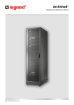
Figure 1-1 shows an RS-232 scanning system setup without an interface
box. Figure 1-2 shows a system with an IB-105 interface box (see “Connectivity with the IB-105” on page A-6).
Object
detector
Host
To power
supply
VS-310
(RS-232)
Figure 1-1 System Diagram (without interface box)
Object
detector
IB-10 5
Junction
box
VS-310
Host
To power
supply
For RS-232, use Cable 61-130014-03 or 61-130019
For RS-422/485, use 61-130024
Figure 1-2 System Diagram (with interface box)
1-2
VS-310 Scanner User’s Manual
Verify Read Range and Scan Width
Verify Read Range and Scan Width
Table 1-1 shows readable ranges and scan widths for specific bar code
density (narrow-bar-width) types. Use this table as a reference to verify
that the planned range for the label falls within one of the listed ranges.
Scan width is that portion of the scan line in which a label can be read.
For ladder oriented labels, scan width must only be wide enough to fully
cover the label length, including quiet zones. With picket fence oriented
labels, scan width is a factor in determining the time in which the label
can be read (see “Calculate Number of Scans” on page 1-4).
Table 1-1 Read Ranges and Scan Widths
Narrow-BarWidth
Read Rangea
Scan Width Data
HIGH DENSITY (60 SPS)
.005" (0.15 mm)
2.25" to 3.0" (5.72 to 7.62 cm)
3.15" @ 2.75"
(8.0 @ 6.99 cm)
.0075" (0.191 mm)
2.0" to 3.5" (5.08 to 11.43 cm)
4.0" @ 2.75"
(10.16 @ 6.99 cm)
LOW DENSITY (100 SPS)
.0075" (0.191 mm)
2.5" to 4.5" (6.35 to 11.43 cm)
4.0" @ 2.75"
(10.16 @ 6.99 cm)
.010" (0.254 mm)
2.0" to 5.5" (5.08 to 13.97 cm)
4.0" @ 2.75"
(10.16 @ 6.99 cm)
.015" (0.381 mm)
2.0" to 6.5" (5.08 to 16.51 cm)
4.0" @ 2.75"
(10.16 @ 6.99 cm)
.020" (0.508 mm)
2.0" to 7.25" (5.08 to 18.42 cm)
4.0" @ 2.75"
(10.16 @ 6.99 cm)
a. Read range is the distance from the front of the scanner to the label in which the label can
be reliably read. The distance between the minimum and maximum ranges is the depth of
field.
Note: Optimum decode rates can be expected at the center of the depth
of field (halfway between minimum and maximum read range) for a given
bar code density.
For information on label orientation, see Appendix G, “Orientation.”
VS-310 Scanner User’s Manual
1-3
1–Setup and Inst.
2
1–Setup and Inst.
Chapter 1
3
Setup and Installation
Calculate Number of Scans
To ensure reliable scanning, we recommend a minimum of five scans per
label. Use the formulas below to calculate the number of scans that the
label will receive. For definitions of terms, see inset on page 1-5.1
If the number of scans derived from one of these calculations is less than
the minimum for the application, plug in the minimum number of scans
and solve for another parameter that might be changed, such as label
speed or scans per second.
Note: Scans per second is 100 for low density option and 60 for high den-
sity option.
Ladder Calculation
LH
-------- × SR – 2 = number of complete scans
LS
Where LH = Label Height, LS = Label Speed, and SR = Scan Rate.
Direction of label travel
LH = 1 inch
LS = 5 inches per second
SR = 100 scans per second
Scan Line
1--- × ( 100 ) – 2 = 18 complete scans
5
Picket Fence Calculation
Figure 1-3 Ladder Orientation
SW – LL ) (------------------------× SR – 2 = number of complete scans
LS
Where SW = Scan Width, LL = Label Length,
Direction of label travel
LS = Label Speed and SR = Scan Rate
Scan Line
SR = 100 scans per second
4 – 2)
(---------------× 100 – 2 = 98 complete scans
2
Figure 1-4 Picket Fence
Orientation
1. The -2 component is added to allow for AGC acquisition and for incomplete first or
last scans.
1-4
VS-310 Scanner User’s Manual
Calculate Number of Scans
1–Setup and Inst.
Angled Picket Fence Calculation
Direction of label travel
The number of complete scans for
angled picket fence is calculated the
same as that for picket fence, with the
exception that the scan width is shortened in proportion to scan tilt.
Scan Line
Figure 1-5 Angled Picket
Fence Orientation
• Scan Rate (SR) is the number of scans per second that a given
scanner is capable of emitting.
• Scan Width (SW) (picket fence formula only) is the width
across the scan beam, at a given distance from the scanner, in
which a label can be read.
• Label Speed (LS) is the
distance per second that a
label moves as it travels
through the scan lines.
• Label Length (LL) (picket
fence formula only) is the
length of the longest
printed label to be read plus
the length of the quiet
zones (figure 1-6).
Label Length
Label height
Quiet zones
Figure 1-6 Label Dimensions
• Label Height (LH) (ladder formula only) is a measurement of the
height of individual bars (figure 1-6).
Note: The formulas given here solve for the predicted number of scans;
you may also assign a value for number of scans (3 or more) and to solve
for other parameters that might be changed, such as label speed, etc.
VS-310 Scanner User’s Manual
1-5
1–Setup and Inst.
Chapter 1
4
Setup and Installation
Attach Cabling
If your VS-310 is an RS-232 option (see table A-4 on page A-3) refer to
the “RS-232 Options” column in table 1-2. If it’s an RS-422/485 option,
refer to the “RS-422/485 Options” column.
If you are making up a custom cable, see “Mating Connector” on page A-4
for instructions on assembling the mating connector kit (Microscan P/N
98-200021-01) included with the VS-310 scanner.
You can also order a Microscan 9-pin to 15-pin cable as described in
Appendix C, “Accessory Cables,” on page A-5 for connection to the
IB-105 interface box or other device. See also “IB-105 Connectors and
Pinouts” on page A-10.
Table 1-2 9-pin, mini-Din Connector
Pin No.
RS-232 Options
1
2
3
4
5
6
7
8
9
Shield
+5 VCC
Output-1a
RS-232 RXD
Signal Ground
RS-232 TXD
Trigger input
Default pin
Output-2a
RS-485 Driver Enable
Chassis Groundb
RS-422/485 Options
+5 VCC
Output-1a
TX +
Signal Ground
TX –
Trigger input
Default pin
RX +
RX –
Chassis Ground
a. can sink 3.5 mA or source 60 µA
b. Chassis g round and signal ground are internally connected through a zero
ohm resistor.
9
6
3
2
Figure 1-7 9-pin mini-Din Connector
1-6
VS-310 Scanner User’s Manual
7
1
Install ESP™
Install ESP™
To install the ESP™,
a. Make a backup copy of the ESP™ disk(s).
b. Start the setup.exe program and follow the on-screen directions to
install ESP™. You will see a screen similar to figure 1-8.
Pull-down menus
Toolbar
Serial port
Auto baud
Settings window
Auto baud status
Figure 1-8 Basic ESP™ Menu
c. Proceed to Step 6.
Note: ESP™ menu commands can be carried out by mouse or by key-
stroke by pressing the Alt key and typing in the appropriate underlined
letter(s) of the menu or command.
VS-310 Scanner User’s Manual
1-7
1–Setup and Inst.
5
1–Setup and Inst.
Chapter 1
6
Setup and Installation
Establish Communications
To establish communications,
a. Select Serial Port and Configure from the pull-down menus.
b. Make your port selection
from Serial Port options
COM 1 through COM 4 (usually COM 2 for desktops and
COM 1 for laptops).
c. Click SEND/RECV button
on the main menu to see
the transfer dialog
(figure 1-9).
d. If you want to copy the settings from your scanner to
the host computer, click
SEND TO SCANNER.
Figure 1-9 Scanner Configuration Transfer
e. To transfer your current host file settings to the scanner, click
RECEIVE FROM SCANNER. If Match Serial Port to Menu Settings is
checked, the current menu settings as listed in the settings window
will be copied to the host’s serial port as well as sent to the scanner.
The default settings for the scanner are 9600 baud, Even Parity, 7
Data Bits, and 1 Stop Bits.
f. If after some delay you get an
“Upload from scanner has timed out!”
message, click the Auto Baud button
(figure 1-8) or select Auto Baud from
Serial Port pull down menu.
Allow some time for the auto baud routine
to test most of the combinations. You can
Figure 1-10 Error Messages
watch this at the bottom of the dialog box.
Once it has found it, it will change the host’s settings to match the scanner’s.
If Upload Status shows
Passed in all categories
(as shown in figure1-11),
then go to Step 7, “Configure Scanner,” on
page 1-9.
Note: Auto Baud does not
test for Com ports. This
requires manual entry.
1-8
Figure 1-11 Upload Status
VS-310 Scanner User’s Manual
Configure Scanner
Configure Scanner
Settings for Communications, Operations, Code Types, and Scanner Output
are loaded into the scanner’s RAM from a Windows-based configuration
program by menu (see Chapter 2, “Configuration Setup File”) or by serial
command (Chapter 3, “Serial Configuration”) from an ASCII terminal.
For explanations of configuration settings, see Chapter 2, “Menu Configuration.”
For a list of serial configuration commands, see Chapter 3, “Serial Configuration.”
Figure 1-12 ESP™ Configuration Menus
Note: When you save communications changes to the scanner, serial port
settings are automatically matched.
Note: You can check your scanner’s settings at any time by clicking
SEND/RECV and RECEIVE FROM SCANNER to upload the scanners current
settings.
VS-310 Scanner User’s Manual
1-9
1–Setup and Inst.
7
1–Setup and Inst.
Chapter 1
8
Setup and Installation
Position Scanner and Label
Before testing the decode rate, you will need to position the scanner and
label in a manner that matches as nearly as possible the actual conditions
of your application.
Bar code
label
a. Position the scanner and
label, taking care to avoid
excessive tilt, skew, or
pitch.1
Skew
axis
Tilt
axis
Scanner
+
Pitch
axis
b. Pitch label (or scanner)
slightly up (at least 2°) or down
(at least 7°) as shown in figure 1-14 to avoid specular
reflection, the return of direct,
non-diffused light.2
Note: If this label were moving
from left to right (or vice
versa), the orientation of the
label, relative to the scan
Figure 1-13 Tilt, Skew, and Pitch Axes
beam, would be “picket fence;”
if the label were moving from top to bottom (or vice versa), the orientation of the label, relative to the scan beam, would be “ladder.”
Scan line
For more information, see Appendix G, “Orientation,” on page A-17.
Avoid this zone
Scanner
Specular
8.9°zone
reflection
-7° to +2°
Figure 1-14 Specular Reflection Zone
1. Maximum tilt is determined by label characteristics and number of scans required.
Maximum skew is ±40°; maximum pitch is ±50°.
2. The specular reflection zone is a narrow arc on the label’s pitch axis -7° to +2° relative to the scanner in which direct reflected light from the label can distort the scanner’s ability to distinguish bars from spaces.
1-10
VS-310 Scanner User’s Manual
Do Decode Rate Test
Do Decode Rate Test
To begin the decode rate test:
a. Position the label in front of a functioning scanner; enter the read
rate test from the ESP™ terminal mode as described in “Enter Percent Test” on page 4-4.
b. Observe decode rate.
c. Check depth-of-field (minimum/maximum range) by moving the label closer and
further relative to the scanner and noting the
points where the decode rates fall below a
level acceptable to your application.
d. Ideally, the label used in your application should pass through or near the center
of the depth-of-field.
33 Decodes/Sec 0123456
33 Decodes/Sec 0123456
33 Decodes/Sec 0123456
33 Decodes/Sec 0123456
33 Decodes/Sec 0123456
Decode Rate
per Second
Label Data
e. Repeat steps a through c for other labels used in your application.
If the decode rate is acceptable, go to Step 11, “Install Scanner,” on
page 1-13. If the decode rate is unacceptable, go to Step 10, “Adjust
Other Scanning Parameters,” on page 1-12.
Note: If, after making adjustments, the read range or another parameter
used in the number of scans formula has changed, recalculate the number
of scans (Step 3, “Calculate Number of Scans,” on page 1-4).
Note: Variations between labels are common. For this reason, the greater
number of sample labels tested, the more likely you are to achieve optimum decode rates.
VS-310 Scanner User’s Manual
1-11
1–Setup and Inst.
9
1–Setup and Inst.
Chapter 1
Setup and Installation
10 Adjust Other Scanning Parameters
This section lists various adjustments that may improve decode rates.
After changing any of the parameters described in this section,
a. If applicable, recalculate the number of scans (Step 3, “Calculate
Number of Scans,” on page 1-4).
b. Repeat Step 9, “Do Decode Rate Test,” on page 1-11.
c. Compare the new decode rate results with those obtained before
changes were made.
Range
Adjusting the label’s range, if possible, is one of the quickest and most
effective ways to improve decode rates.
Scan Width
Increasing scan width will increase the number of scans in a picket fence
oriented application. Scan width is linked with scan range and changing
one will usually require a change in the other.
Label Speed
Applies to both picket fence and ladder oriented labels. If your application
allows it, label speed (the time in seconds that a label is fully within the
scan width of the scanner) is an effective way to alter the number of
scans.
Label Dimensions, Label Density, and Label Ratio
Not usually an option in most applications, but changes to label parameters can affect number-of-scan calculations and possibly decode rates.
If your application allows it, shortening the length of a picket fence label
means the label will be in the scan range longer and hence receive a
greater number of scans. Increasing bar height of a label in ladder orientation means the label will receive more scans. Changing label density
and/or bar code ratio is another way ranges, decode rates, etc. can be
altered.
1-12
VS-310 Scanner User’s Manual
Install Scanner
1–Setup and Inst.
11 Install Scanner
The VS-310 scanner can be
top or bottom mounted as
per dimensions shown in
figure 1-15.
2.29"
5.82 cm
To permanently mount the
scanner:
a. Position the scanner
in a place devoid of
sunlight, bright lights,
or laser light from
other sources.
b. Drill two 0.128 inch
(3.25 mm) diameter
holes 2.29” (5.82 cm)
apart as per
figure 1-15.
M4 threaded
mounting holes
(2 places)
1.10"
2.79 cm
0.3"
2.15"
5.46 cm
Bottom
.762 cm
Not threaded
P
D
TM
1.10"
2.79 cm
Caution: Maximum pene-
tration depth of screws is
0.200 inch (5.08 mm).
M4 threaded
mounting holes
(2 places)
Top
Figure 1-15 Mounting Holes and
Dimensions (not to scale)
VS-310 Scanner User’s Manual
1-13
1–Setup and Inst.
Chapter 1
Setup and Installation
12 Position Object Detector
If you are not using an object detector, ignore this step.
In a typical operation, a scanner will wait for bar code data only during a
triggered read cycle. A read cycle is initiated by a “trigger” that can be in
the form of a serial command from the host (internal trigger) or a signal
from an object detector (external trigger).
When an object detector is used, it is set up so that its beam will bounce
off the approaching object and the resulting pulse will be sent to the
scanner to begin the read cycle. Typically, a detector is positioned so that
it will detect the presence of an object before the object’s label can be
scanned by the scanner.
An object detector is mounted
in almost any position relative
to the object as long as (1)
the object passes within range
of the detector and (2) direct
or reflected light from the
detector does not interfere
with the scanner’s reception.
As the item continues to move
down the line, its label moves
into the scanner beam and is
read by the scanner.
Label
Detector
Scan beam
Direction of
label travel
Scanner
Figure 1-16 Detector Orientation
Figure 1-16 shows a picket
fence label being scanned with
the detector and scanner at right angles to each other.
1-14
VS-310 Scanner User’s Manual
Operational Tips
Do:
• Check inputs (label speed, length, height, etc.) to ensure the desired
number of scans per label.
• Avoid excessive tilt, pitch, and skew of the bar code label.
• Check the label for readability by doing a decode rate test. If there is
any question about the label's readability, contact your Microscan representative.
• After changing any parameter that might affect decode rate, repeat
decode rate test.
• Clean the scanner window with a clean, dry Q-tip or cotton cloth on a
regular basis.
Do Not:
• Aim the scanner into direct light or sunlight.
• Aim the scanner into an external object detector or other light-emitting
device.
• Obstruct the scanner window with mounting hardware or other objects.
• Connect chassis of scanner and host to different ground potentials (see
appendix H on page A-19).
• Operate the scanner in excessive temperature environments (see
“ENVIRONMENT” on page A-2).
VS-310 Scanner User’s Manual
1-15
1–Setup and Inst.
Operational Tips
Setup and Installation
1–Setup and Inst.
Chapter 1
1-16
VS-310 Scanner User’s Manual
Chapter
2
Menu
Configuration
Using ESP™ to Configure the Scanner................................................... 2-2
Communications Menu............................................................................ 2-4
Protocol ................................................................................................... 2-6
Operations Menu ................................................................................... 2-10
Code Types Menu ................................................................................. 2-16
Scanner Outputs Menu.......................................................................... 2-21
This chapter tells how to configure the VS-310 scanner using the ESP™ program on a Windows based (Windows 3.1™ or Windows 95™) computer.1
The ESP™ program can be thought of as two programs: one for use in configuration, the other for use in testing and operations. Configuration is covered in this chapter; testing and operations are covered in Chapter 4.
Microscan’s ESP™ will allow the user to quickly configure the VS-310 scanner and save multiple configuration files to the host or setup computer which
in turn can be used to archive or download settings to other scanners.
After changes are made in the configuration menus, they can be downloaded
in total to the scanner and the current settings will be posted in a status window. It is important to note that configuration settings can be saved in two
distinct ways: to the scanner or to the host computer.
Note: See Step 5, “Install ESP™,” on page 1-7 and Chapter 4, “Utilities,”
for testing and operational uses of the ESP™ program.
1. Before installing the program you should have a working acquaintance with the Windows® platform. See Microsoft Windows® literature and Help files for additional
information.
VS-310 Scanner User’s Manual
2-1
2–Menu Config.
Chapter Contents
Chapter 2
Menu Configuration
Using ESP™ to Configure the Scanner
Figure 2-1, “Configuration Setup File,” shows the window you will see when
you launch the Easy Setup Program.
Pull down menus
2–Menu Config.
Toolbar
An “Untitled...” file loads
with the original factory
default settings
Access configuration
menu changes here.
Emulation window
displays echoed
commands and data
Also titled
“Current Menu/Scanner
Settings” following a save
or upload
You can also access the
configuration menus by
double clicking any item
here.
Allows you to perform
tests and access
operational information
Allows you to
download/upload
between the scanner and
the host
Figure 2-1 Configuration Setup File
To access the configuration menus, press the MENU button.
If using a mouse, single click on menu items and enter text as appropriate.
If using the keyboard, use the Alt key plus underlined letters and the tab key
to move to the desired field, use arrow keys or the space bar to scroll
through selections, and the Enter key to accept changes.
2-2
VS-310 Scanner User’s Manual
Using ESP™ to Configure the Scanner
Saving Settings to the Scanner
You can access the SEND/RECV box by clicking it directly from the Current
Main menu, or after making changes from within any of the configuration
menus, clicking Apply. (Clicking OK on these menu pages will only update
the items in the Current Settings window.) From within the SEND/RECV
box, click SEND TO SCANNER to initialize and reset counters only, or SEND/
SAVE to initialize, reset counters, and save these settings to the scanner’s
nonvolatile memory. (See figure 2-1 on page 2-2.)
2–Menu Config.
Uploading Settings
To update current settings from the scanner
(from RAM), click SEND/RECV and then
RECEIVE FROM SCANNER.
Note: If receiving scan data and you are in
Continuous Read, labels being scanned may
interfere with your data request (figure 2-2).
Figure 2-2 Upload Error
Saving Settings to the Host Computer
When saving a file by clicking SAVE AS (or SAVE) from the File pull-down
menu, the settings are saved only on the computer’s hard drive or other
storage medium. This is particularly useful for saving special sets of settings that you may want to recall later and use for a different application.
Creating a New Configuration File
To create a new file of configuration settings, first be sure you’ve saved the
current configuration file to the computer’s hard drive or other storage
device. Next pull down the File menu in the ESP™ and click New. A new
Untitled window will open with a listing of the factory default settings.
Change these settings to suit your requirements and save this file to the
computer’s hard drive under a new name. These settings can also be downloaded to the scanner at any time under a name of your choice.
Restoring Factory Default Settings
Note: Be certain that you’ve saved any other configuration files to the
host computer that you may want to reload later.
Default settings can be reset for individual menus pages or for all menus at
once. To restore factory defaults for individual menus (Communications,
Operations, Code Types, or Scanner Settings), click the DEFAULT button on
the specific menu.
To restore factory defaults for ALL settings in the scanner, click the DEFAULT
button on the Reset page of the Utilities menu, or click New in the File pulldown menu.
VS-310 Scanner User’s Manual
2-3
Chapter 2
Menu Configuration
Communications Menu
2–Menu Config.
The Communications menu allows you to set the communication protocols of
the scanner. (See figure 2-3.).
Figure 2-3 Communications Menu Structure
Note: When you make and save menu communications changes to the
scanner, those changes will automatically be matched in the Serial Port
configuration.
Default
Clicking the DEFAULT button will reset all options on the Communications
menu to factory defaults. This does not affect any other menus and it does
not take effect until it is saved to the scanner with the SEND TO SCANNER
or the SEND/SAVE buttons under SEND/RECV.
2-4
VS-310 Scanner User’s Manual
Communications Menu
Parity
Default:
Options:
Even
Even, Odd, None
Allows you to choose an error detection routine in which one data bit in each
character is set to 1 or 0 so that the total number of 1 bits in the data field is
even or odd.
Data Bits
Seven
2–Menu Config.
Default:
Options:
Seven, Eight
Allows you to establish the total number of bits in each character.
Stop Bits
Default:
Options:
One
One, Two
Allows you to choose the last one or two bits in each character to indicate
the end of the character.
Baud Rate
Default:
Options:
9600
300, 600, 1200, 2400, 4800, 9600, 19.2K
Allows you to set the number of bits transmitted per second.
VS-310 Scanner User’s Manual
2-5
Chapter 2
Menu Configuration
Protocol
2–Menu Config.
The Protocol menu allows you to choose your communications protocol and
associated output data format.
Figure 2-4 Protocol
Default
Clicking the DEFAULT button will reset all options on the Protocol menu to
factory defaults. You can then click Apply followed (in the pop-up dialog
box) by SEND TO READER or SAVE TO READER.
Selected Protocol
Default:
Point-to-Point
Options:
Point-to-Point, Point-to-Point with XON/XOFF, Polling Mode D,
Multidrop, User Defined, User Defined Multidrop
Protocols define the sequence and format in which information is transferred
between devices.
Point-to-Point
Has no address and sends data to the host (RS-232) whenever it is available
and without any request or handshake from the host.
2-6
VS-310 Scanner User’s Manual
Protocol
Point-to-Point with XON/XOFF (Transmitter On/Off)
Used only with RS-232. This selection enables the host to send a single byte
transmission command of start (XON) or stop (XOFF). If an XOFF has been
received from the host, data will not be sent to the host until the host sends
an XON. During the XOFF phase, the host is free to carry on other chores
and accept data from other devices.
Polling Mode D
Multidrop
Note: Readers intended to link up to a Microscan MS-5000 multidrop con-
centrator must be configured in standard Multidrop protocol.
Note: To avoid slow or degraded performance when the VS-310 is net-
worked with Microscan’s MS-5000 multidrop concentrator, the MS-5000
must have Turnaround Timeout set to 35 ms and should have Baud Rate
set to 19.2 and Number of Devices set to no more than the actual number
of connected devices. See MS-5000 Multidrop concentrator User’s Manual.
Similar to Polling Mode D except that a unique poll address and select
address are required for each multidrop device, and only one host port connection is needed for up to 50 devices. (For Multidrop poll and select characters, see Table A-E, “ASCII Table,” on page A-12.)
Requires a concentrator or controller using RS-485 communications. When
Multidrop is selected, the protocol characters for RES, REQ, etc. are assigned
automatically. (See Table A-11, “ASCII Table with Control Characters,” on
page A-12 for poll and select sequences.)
User Defined
Note: A specific ASCII character must not be assigned more than once.
Used only with RS-232. User Defined is necessary when a new protocol must
be defined to match a specific host protocol. ASCII characters can be
assigned as an address and as protocol commands (RES, REQ, EOT, STX,
ETX, ACK, NAK, From Host). In order to enable a handshaking protocol, you
must manually assign values where necessary. When User Defined is
selected, the displayed protocol commands match those of the previously
selected protocol. User Defined is considered to be in a polled mode only if
an address has been assigned. The address can be any ASCII character from
Table A-11, “ASCII Table with Control Characters,” on page A-12. If null is
selected as the address, the reader will not function in a polling sequence.
VS-310 Scanner User’s Manual
2-7
2–Menu Config.
Like Point-to-Point, Polling Mode D requires a separate connection to the
host; but unlike Point-to-Point, it requires an address and must wait for a
poll from the host before sending data. When in Polling Mode D, an address
of 1 is automatically displayed on the configuration screen. However, during
transmission, a 1C hex poll address (FS) and a 1D hex select address (GS)
are substituted for the 1.
Chapter 2
Menu Configuration
From Host, if enabled, allows the handshaking protocol to be initiated from
the host, if unpolled.
Default:
Disabled
Options:
Disabled, Enabled
2–Menu Config.
From Host
When enabled, messages sent to the host from the VS-310 will always
include the reader’s defined protocol. The status of From Host determines if
messages sent to the VS-310 from the host must also include the defined
protocol. If From Host is disabled, the defined protocol is not included. If
From Host is enabled, the defined protocol must be included. (See “From
Host,” on page 2-8 for further information.)
Default:
Disabled
Options:
Disabled, Enabled
User Defined Multidrop
Used when connecting to a concentrator or other device that does not
match standard Multidrop protocol.
Any single character (01 hex to 7E hex) in the ASCII table can be assigned
as the address character. The character chosen is used as the poll character
and the subsequent ASCII character becomes the select character. For
example, if a ^A (01 hex) is selected as the address, ^B (02 hex) becomes
the select address that the host will use in sending host select commands.
(See table A-16 on page A-16.)
Note: Definitions of commands in User Defined and User Defined Multi-
drop must be duplicated in host applications to enable poll and select
sequences to execute correctly during transmission.
Note: Typically, parameters in User Defined Multidrop are defined by first
enabling Multidrop, then enabling User Defined Multidrop. This pre-loads
Multidrop characters into the parameters. You then change individual
characters to match the host or other requirements.
Preamble
Preamble (enable/disable)
Default:
Disabled
Options:
Disabled, Enabled (within any protocol)
Allows you to enable or disable the preamble character(s).
Preamble (definition)
2-8
Default:
CR (carriage return).
Options:
Up to two ASCII characters except NUL, <, or >.1
VS-310 Scanner User’s Manual
Protocol
If enabled, allows you to define up to two characters that can be added in
front of the symbol data. For example, a carriage return.
Postamble
Postamble (enable/disable)
Default:
Enabled
Options:
Enabled, Disabled (within any protocol)
Allows you to enable or disable the Postamble character(s).
Default:
Options:
CR LF (carriage return/line feed).
Up to two ASCII characters except NUL, <, or >.1
Allows you to define up to two characters that can be added after the symbol
data. When enabled, the default CR LF causes each symbol to be displayed
on its own line.
Response Timeout (character)
Default:
4 (40 ms)
Options:
0 to 255 (in 10 ms increments)
Allows you to set the time the reader will wait between characters before
timing out if ACK, NAK, and ETX are enabled, and a host response is
expected.
Intercharacter Delay
Default:
0
Options:
0 to 255 in 60 ms increments. Zero (0) causes no delay
between characters.
Allows you to set the time interval in milliseconds between individual characters transmitted from the VS-310 to the host computer. A high setting will
significantly slow down communications. For example, a 200 setting will
result in a 2 second delay between each character that is transmitted.
Longitudinal Redundancy Check (LRC)
Default:
Disabled
Options:
Disabled, Enabled
An error-checking routine that verifies the accuracy of transmissions. It is
the exclusive OR of all characters in the transmitted message. The result is
appended to the end of the transmitted message.
1. In the case where only one character is entered, a NUL character is selected to serve
as a place holder; however, no output will result.
VS-310 Scanner User’s Manual
2-9
2–Menu Config.
Postamble (definition)
Chapter 2
Menu Configuration
Operations Menu
The Operations menu allows you to set the operations parameters for the
scanner. (See figure 2-5.)
2–Menu Config.
Note: Clicking the DEFAULT button will only restore those settings of the
specific menu on which the button appears.
Figure 2-5 Operations Menu
Default
Clicking the DEFAULT button will reset all options on the Operations menu to
factory defaults. This does not affect any other menus and it does not take
effect until it is saved to the scanner with the SEND TO SCANNER or the
SEND/SAVE under SEND/RECV.
Triggering Mode
Default:
Options:
Continuous Read
Continuous Read, continuous read 1, External Level, External
Edge, Serial Data, Serial Data & External Edge
Allows you to establish the type of trigger event that will initiate or end the
read cycle. (See “End of Read Cycle” on page 2-12.)
2-10
VS-310 Scanner User’s Manual
Operations Menu
Continuous Read
Trigger input options are disabled and the scanner is always in the read
cycle. Bar code data is decoded, and label information is transmitted repeatedly, as long as the label is in the read range of the scanner. When To Output
options have no affect on Continuous Read. Continuous Read is useful in
testing label or scanner functions.
Note: If Match Code is enabled, the scanner defaults to Continuous Read 1.
Continuous Read 1
With End Of Read Cycle set to New Trigger, the scanner outputs the current
label data immediately, but outputs it only once. A new label appearing at
any time in the scan range will produce a new read output as long as the
new label is not identical to the previous label.
Note: Continuous Read 1 will default to Continuous Read when I 2 of 5
code length is enabled for greater than 30.
Note: If Continuous Read 1 is enabled, Number of Labels (page 2-15) will
default to one (if set for 2) and UPC Supplementals Enabled will not be
available.
External Level
Allows a read cycle to be initiated by a trigger signal from an object detector
when an object appears within the detector’s range. The read cycle continues as long as the detector “sees” the object and ends when the object
moves out of the detector’s range.
Primary Trigger
When an object moves into the range of
the detector beam, a primary (first) trigger
signal (positive or negative) is received by
the scanner, initiating the read cycle.
1
Object
detector
1
Secondary Trigger
Object
detector
When the same object moves out of
the detector's beam, a second trigger
signal (positive or negative) is received
by the scanner, ending the read cycle.
Figure 2-6 External Level Trigger Events
VS-310 Scanner User’s Manual
2-11
2–Menu Config.
Label data is immediately transmitted once every time new label data is
placed in front of the scanner. With End Of Read Cycle set to Timeout and
the label not changed, the scanner repeats the output at the end of each
timeout period. For example, if Timeout is set to one second, the scanner
outputs the label data immediately, and then repeats the output at intervals of one second, for as long as the label continues to be scanned.
Chapter 2
Menu Configuration
External Edge
As with Level, a read cycle is initiated by a trigger signal from an object
detector when it detects the arrival of an object (first edge). But unlike
Level, the departure of an object does not end the read cycle. With Edge
enabled, the read cycle ends with a new trigger caused by the arrival of a
subsequent object, unless a good read or timeout occurs first.
First edge
When object # 1 moves in front of the
detector beam, a trigger signal (positive or
negative) is received by the scanner, initiating
the read cycle.
2–Menu Config.
1
Object
detector
Subsequent edge
When object # 2 moves in front of the detector's
beam, a trigger signal (positive or negative) is
received by the scanner, initiating a new read
cycle and ending the previous read cycle (unless
the previous read cycle has already been ended
by a good read or timeout).
2
Object
detector
Figure 2-7 External Edge Trigger Events
Serial Data
The scanner accepts an ASCII character from the host or controlling device
as a trigger to start a read cycle. Serial data trigger behaves the same as
External Edge.
Serial Data & External Edge
The scanner accepts either an external trigger or a serial ASCII command to
start a read cycle.
End of Read Cycle
Default:
Options:
Timeout
Timeout, New Trigger, Timeout & New Trigger
Allows you to choose the circumstances that will end the read cycle. The
read cycle is the time during which the scanner will receive and process label
data. When Triggering Mode is set to External or Serial, the trigger event initiates the read cycle.
Note: When operating in Continuous Read or Continuous Read 1, the
scanner is always in the read cycle.
Timeout
Can end the read cycle after a specified period of time, and if no label has
been read, causes a noread message, if enabled, to be transmitted.
2-12
VS-310 Scanner User’s Manual
Operations Menu
With either External Edge, Serial Data, or Serial Data & Edge enabled, a timeout ends the read cycle.
With External Level enabled, the read cycle does not end until the secondary
trigger occurs, and the next read cycle does not begin until the next rising
edge trigger.
With Continuous Read 1 enabled, a timeout initiates a new read cycle and
allows the same label to be read again.
New Trigger
With either External Edge, Serial Data, or Serial Data & Edge enabled, an
edge or serial trigger ends a read cycle and initiates the next read cycle.
With External Level enabled, a secondary trigger, which occurs when the
object moves out of the detector’s range, ends a read cycle. However, the
next read cycle does not begin until the occurrence of the next primary
trigger.
Timeout & New Trigger
Ends the read cycle after a specified period of time or at the occurrence of
new trigger event, and if no label has been read, causes a noread message,
if enabled, to be transmitted.
With either External Edge, Serial Data, or Serial Data & Edge enabled, a timeout, or an edge or serial trigger, whichever comes first, ends the read cycle.
With External Level enabled, the read cycle does not end until the occurrence of a falling edge, and the next read cycle does not begin until the next
rising edge trigger.
Serial Trigger Character
Default:
Options:
GS
Any single ASCII character except NUL, an existing host command character,1 or an on-line protocol character.
Note: Serial Data (page 2-12) or Serial Data & Edge (page 2-12) must be
enabled for Serial Trigger Character to take effect. “N/A” is displayed in
the menu when all other triggering modes are enabled.
Allows you to define a single ASCII character as the host serial trigger character that initiates the read cycle. The serial trigger is considered an on-line
host command and requires the same command format as all host serial
commands (that is, to be entered within the < > brackets).
1. For example, assigning an upper case C would nullify the <C> (Enter Decode Rate
Test) command. For a list of operational commands used by the scanner, see
Chapter 4, “Utilities.”
VS-310 Scanner User’s Manual
2-13
2–Menu Config.
Ends the read cycle at the occurrence of a new trigger event, and if no label
has been read, causes a noread message, if enabled, to be transmitted at
the occurrence of the new trigger event.
Chapter 2
Menu Configuration
Good Decode Reads
Default:
Options:
1
1 to 31
Allows you to choose the number of good reads (from 1 to 31) required per
label before a good decode output.
Note: Be sure to set the value within the determined scan rate for the
2–Menu Config.
scanning setup so that the scanner is capable of scanning a label the
required number of times
External Trigger Level
Default:
Options:
Positive
Positive, Negative
Note: External Level (page 2-11), External Edge (page 2-12), or Serial
Data & Edge (page 2-12) must be enabled for External Trigger Level to
take effect. “N/A” is displayed in the menu when all other triggering
modes are enabled.
Allows you to determine whether a positive or negative transition will initiate
the read cycle.
Note: If using the Microscan object detector (P/N 99-440001-03), use
positive trigger polarity.
Trigger Filter
Default:
Options:
4
0 to 255. (Approximately 0 ms to 1.275 sec in 5 ms incs.)
Multiply the number entered on the command line by 5 for
time in milliseconds.
Allows you to set a trigger bounce filter duration.
Timeout (in 10 ms incs)
Default:
Options:
100 (one second). Corresponds to 1000 ms displayed in the menu.
0 to 65535. Divide the number entered on the command line
by 100 for time in seconds.
Note: Timeout or Timeout & New Trigger under End of Read Cycle (page
2-13) must be enabled for Timeout (in 10 ms incs) to take effect.
Allows you to define the duration of the timeout period.
2-14
VS-310 Scanner User’s Manual
Operations Menu
Match Code
Default:
Options:
Disabled
Disabled, Enabled
Note: Match Code will not function when I 2 of 5 code length is enabled
for greater than 30.
Note: A triggered mode (page 2-14 to page 2-12) must be enabled for
Match Code to take effect.
Allows you to enter a master label into the scanner's memory to be compared with subsequently scanned labels. (See “Master Label” on page 4-9.)
Number of Labels
Default:
Options:
1
1 to 2
Note: If Number of Labels is set to 2 while Match Code or Continuous
Read 1 is enabled, Number of Labels will default back to one.
Allows you to choose the number of different labels that will be read in a single trigger event. The following conditions apply:
1. Each label must have different label data to be read.
2. The maximum number of characters that can be transmitted in any
one label, or in both labels if 2 is enabled, is 64, excluding preamble,
postamble, and all spaces and commas.
3. When 2 is enabled, a noread message for either label will be posted
at the end of the full data string.
4. If more than one label is within the scan beam at the same time,
label data may not be displayed in the order of appearance.
Multilabel Separator
Default:
Options:
, (comma)
Any ASCII character except NUL, <, or >.
Allows you to choose the separator character to be inserted between each label.
VS-310 Scanner User’s Manual
2-15
2–Menu Config.
Note: If Match Code is enabled, Number of Labels will default to 1 (if set for 2)
and UPC Supplementals Enabled will not be available.
Chapter 2
Menu Configuration
Code Types Menu
2–Menu Config.
The Code Types menu allows you to choose among five bar code types and
define their parameters. (See figure 2-8.)
Figure 2-8 Code Types Menu
Default
Clicking the DEFAULT button will reset all options on the Code Types menu
to factory defaults. This does not affect any other menus and it does not
take effect until it is saved to the scanner with the SEND TO SCANNER or
the SEND/SAVE under SEND/RECV.
Code 39
Default:
Options:
Enabled
Enabled, Disabled
Check Digit
Default: Disabled
Options: Disabled, Enabled
Code 39 is self-checking and does not normally require a check digit. However, for additional data integrity, a Modulus 43 check digit can be added to
the bar code message. With Check Digit and an External or Serial trigger
option enabled (see “External Trigger Level” on page 2-14), an invalid
2-16
VS-310 Scanner User’s Manual
Code Types Menu
check digit calculation will cause a noread message to be transmitted at
the end of the read cycle.
Check Digit Output
Default: Disabled
Options: Disabled, Enabled
When enabled, the check digit character is sent along with the label data.
When disabled, label data is sent without the check digit.
Allows the scanner to read labels with gaps between bar code characters
exceeding three times the narrow element width.
Fixed Code Length
Default: Disabled
Options: Disabled, Enabled
Used to increase data integrity by ensuring that only one label length will be
accepted.
Code Length
Default: 10
Options: 1 to 31
Allows you to specify the exact number of characters that the scanner will
recognize (this does not include start and stop). The scanner will ignore any
code not having the specified length.
Codabar
Default:
Options:
Disabled
Disabled, Enabled
Large Intercharacter Gap
Default: Disabled
Options: Disabled, Enabled
Allows the scanner to read labels with gaps between bar code characters
exceeding three times the narrow element width.
Check Digit
Default: Disabled
Options: Disabled, Modulus 16, NW 7, Both
Allows you to choose the type of checksum system Codabar will use.
VS-310 Scanner User’s Manual
2-17
2–Menu Config.
Large Intercharacter Gap
Default: Disabled
Options: Disabled, Enabled
Chapter 2
Menu Configuration
Check Digit Output
Default: Disabled
Options: Disabled, Enabled
When enabled, the check digit character is sent along with the label data.
When disabled, label data is sent without the check digit.
2–Menu Config.
Start & Stop Match
Default: Enabled
Options: Enabled, Disabled
Requires the Codabar start and stop characters (a, b, c, or d) to match
before a valid read can occur.
Start & Stop Output
Default: Enabled
Options: Enabled, Disabled
Allows the start and stop characters to be transmitted with bar code data.
Fixed Code Length
Default: Disabled
Options: Disabled, Enabled
Increases data integrity by ensuring that only label length will be accepted.
Code Length
Default: 10
Options: 1 to 31 (Includes check digit but not start and stop characters)
Allows you to specify the exact number of characters that the scanner will
recognize. The scanner will ignore any code not having the specified length.
Interleaved 2 of 5
Default:
Options:
Disabled
Disabled, Enabled
Because I 2 of 5 is a continuous code, it is prone to substitution errors.
Hence, a code length must be defined and a bar code label containing an
even number of digits must be used. It is also recommended that a Modulus
10 check digit be used to ensure the best possible data integrity.
Check Digit
Default: Disabled
Options: Disabled, Enabled
I 2 of 5 uses a Modulus 10 check digit.
2-18
VS-310 Scanner User’s Manual
Code Types Menu
Check Digit Output
Default: Disabled
Options: Disabled, Enabled
When enabled, the check digit character is sent along with the label data.
When disabled, label data is sent without the check digit.
the next lower number.
With I 2 of 5, two code lengths can be defined. When using only one label
length in an application, we recommend setting Code Length #2 to 0 to
ensure data integrity. If a check digit is used, it must be included in the code
length count.
Note: If Code Length of #1 is greater than 30, then Continuous Read 1
defaults to Continuous Read, Match Code is disabled, and Number of
Labels defaults to 1.
Code Length #2
Default: 6
Options: 0 to 30, even. If you enter an odd number the scanner will use
the next lower number.
If using a second label, you may also specify a zero or any even code length
from 2 to 30. If not using a second label, set Code Length #2 to 0 to ensure
data integrity.
Code 93
Default:
Options:
Disabled
Disabled, Enabled
Fixed Code Length
Default: Disabled
Options: Disabled, Enabled
Allows you to increase data integrity by ensuring that only one label length
will be accepted.
Code Length
Default: 10
Options: 1 to 31
Allows you to specify the exact number of characters that the scanner will
recognize (this does not include start and stop). The scanner will ignore any
code not having the specified length.
VS-310 Scanner User’s Manual
2-19
2–Menu Config.
Code Length #1
Default: 10
Options: 2 to 64, even. If you enter an odd number the scanner will use
Chapter 2
Menu Configuration
Code 128
Default:
Options:
Disabled
Disabled, Enabled
Fixed Code Length
Default: Disabled
Options: Disabled, Enabled
2–Menu Config.
Allows you to increase data integrity by ensuring that only one label length
will be accepted.
Code Length
Default: 10
Options: 1 to 31
Note: Fixed Code Length must be enabled for Code Length to take effect.
Allows you to specify the exact number of characters that the scanner will
recognize. The scanner will ignore any code not having the specified length.
Autodiscriminate
Default:
Options:
Disabled
Disabled, Enabled
Enables all code types simultaneously.
Narrow Margins
Default:
Options:
Disabled
Disabled, Enabled
Allows the scanner to read bar codes with quiet zones less than 10 times the
narrow-bar-width. Quiet zone is a term used to describe the minimum space
at the leading and trailing ends of a label. Each quiet zone can be as small as
five times the narrow bar element when Narrow Margins is enabled.
2-20
VS-310 Scanner User’s Manual
Scanner Outputs Menu
Scanner Outputs Menu
The Scanner Outputs menu allows you to configure the scanner’s output.
2–Menu Config.
Figure 2-9 Scanner Outputs Menu
Note: Bar code output data and noread messages are transmitted on pin
5 under conditions set principally in Bar Code Output. Relay pulses are
transmitted via pins 2 and 8 (Relay-1 and Relay-2 respectively) and individually configured under conditions set in Relay-1 and Relay-2.
Default
Clicking the DEFAULT button will reset all options on the Scanner Outputs
menu to factory defaults. This does not affect any other menus and it does
not take effect until it is saved to the scanner with the SEND TO SCANNER
or the SEND/SAVE under SEND/RECV.
Bar Code Output
Default:
Options:
On Good
On Good, Disabled, Match, Mismatch
If Bar Code Output is set to Match or Mismatch, label data will not output
unless Match Code (page 2-16) is enabled and a master label is downloaded
into memory. Allows you to choose the conditions that will send label data
(or noread messages) to the host computer.
VS-310 Scanner User’s Manual
2-21
Chapter 2
Menu Configuration
Disabled
The scanner will not output either label data or noread messages to the
serial port.
Match (with Match Code enabled)
The scanner will output when the label data information matches the master
label. However, if Match Code is disabled it will output on any good read.
Mismatch (with Match Code enabled)
2–Menu Config.
The scanner will output when the label data information does not match the
master label. However, if Match Code is disabled it will output on any good read.
When to Output (bar code data)
Default:
Options:
As Soon As Possible
As Soon As Possible, End of Read Cycle
Allows you to choose when bar code data is sent to the host computer.
As Soon As Possible
Causes bar code data (good reads) to be transmitted immediately upon a
good decode.
End of Read Cycle
Causes bar code data output to be delayed until the end of the read cycle.
Beeper Status
Default:
Options:
On Good
On Good, On Noread, Disabled
A beep is emitted either after each good read of a bar code label or after
each noread.
Beeper Speed
Default:
Options:
Fast
Fast, Slow
Allows you to control the duration of the sound emitted by the beeper.
Noread Message
Default:
Options:
NOREAD
Up to seven ASCII characters (except NUL).
Allows you to define any combination of ASCII characters (except NUL) up to
seven characters as the noread message. When enabled, the noread message will be transmitted to the host at a timeout or the end of a read cycle if
the bar code label has not been decoded.
2-22
VS-310 Scanner User’s Manual
Scanner Outputs Menu
Enable Laser On/Off
Default:
Options:
Disabled
Disabled, Enabled
Note: A serial or external trigger (see “External Trigger Level,” on page
2-14) must be enabled for Laser On/Off to take effect.
When enabled, the laser is ON only during the read cycle. When disabled,
the laser operates continuously.
<I> (Disable Laser Scanning) operational commands on page 4-6.
Enable Noread
Default:
Options:
Enabled
Enabled, Disabled
Note: If Noread Output is enabled, the noread message will only output if
Bar Code Output (page 2-21) is also enabled.
Allows you to enable or disable the noread message.
Relay 1 and Relay 2
Relay 1 and Relay 2 can allow simultaneous output on pins 2 and 8 respectively under individually programmed conditions. The following parameters
(Output On, Polarity, and Pulse Width) are individually configured in ESP™,
but described only once here.
Note: Relay 2 is not available if using an RS-422/485 version.
Polarity
Default:
Options:
Negative
Negative, Positive
Allows you to choose between positive and negative output signals for the
relay output pin that is enabled.
Pulse Width (in 10 ms incs)
Default:
Options:
5 (.05 seconds). Corresponds to 50 ms displayed in the menu.
0 to 255 (0 to 2.55 seconds). Divide the number entered on
the command line by 100 for time in seconds.
Allows you to set the duration of the good match/noread output signals at
the relay output pin that is enabled.
VS-310 Scanner User’s Manual
2-23
2–Menu Config.
Note: Laser On/Off does not relate to the <H> (Enable Laser Scanning) or
Chapter 2
Menu Configuration
Output On
Mismatch or Noread
Default:
Options:
Mismatch or Noread, Match, Mismatch, Noread
Allows you to set the conditions that will output a relay pulse. To see the
options for enabling Match Code and downloading a master label into memory. (See “Master Label,” on page 4-9.)
Mismatch or Noread
2–Menu Config.
Sends a pulse to the relay output pin(s) when the following conditions are
met:
1. Match Code is disabled and a noread occurs; or
2. Match Code is enabled (page 2-15), and ANY of the following is true:
a. a label is decoded and does not match the master label,
b.
c.
there is no master label in memory (page 4-9), or
a noread occurs.
Noread
Sends a pulse to the relay output pin(s) when the label’s data is not decoded
before the end of the read cycle regardless of the status of Match Code.
Match
Sends a pulse to the relay output pin(s) if the following conditions are met:
1. Match Code is disabled and a label is decoded; or
2. Match Code is enabled (page 2-15) and ALL of the following are true:
a.
b.
A master label is downloaded into memory (page 4-9),
A label is decoded, and
c.
The decoded label matches the master label
Mismatch
Sends a pulse to the relay output pin(s) that is enabled if ALL of the following conditions are met:
1. Match Code is enabled (page 2-15).
2. A label is decoded.
3. The decoded label does not match the master label or there is no
master label in memory (page 4-9).
2-24
VS-310 Scanner User’s Manual
Chapter
3
Serial
Configuration
Chapter Contents
All of the configuration changes to the scanner that can be made in the
menu program can also be accomplished by command strings from the
host.
Serial command strings are entered from an ASCII terminal or from
within the Terminal window of the Easy Setup Program for Windows. As
with menu configuration commands, serial configuration commands
relate to the initial scanner setup.
To quickly reference the serial configuration commands, see table 3-1 on
page 3-2.
See Menu commands in Chapter 2 for detailed explanations of configuration commands.
VS-310 Scanner User’s Manual
3-1
3–Serial Config.
Summary of Serial Configuration Commands...................................... 3-2
Serial Configuration Command Format ............................................... 3-3
Concatenating Serial Commands ........................................................ 3-4
Establishing Communications.............................................................. 3-4
Communications .................................................................................. 3-5
Protocol................................................................................................ 3-5
Operations Commands ........................................................................ 3-8
Code Types Commands .................................................................... 3-10
Scanner Output Commands .............................................................. 3-12
Scanner Setup Commands................................................................ 3-13
Chapter 3
Serial Configuration
Table 3-1 Summary of Serial Configuration Commands
Type
Communic
ations
Protocol
3–Serial Config.
Operations
Code
Types
Scanner
Outputs
Scanner
Setup
3-2
ESP
Cmd Cmd
?
Name
Format
Yes
Ka
Communications
<Kabaud,parity,stop bits,data bits>
Yes
Yes
Yes
Yes
Yes
Yes
Yes
Yes
Yes
Yes
Yes
Yes
Yes
Yes
Yes
Kf
Kd
Ke
Kc
KA
KB
Km
KL
Ki
Kg
Kh
Kj
Kn
Ko
Kp
Protocol
Preamble
Postamble
LRC
Response Timeout
Intercharacter Delay
Good Decode Reads
Number of Labels
Serial Trigger Character
Triggering Mode
End of Read Cycle
External Trigger Level
Match Code
Narrow Margins
Code 39
<Kfprotocol>
<Kdstatus,ASCII characters>
<Kestatus,ASCII characters>
<Kcstatus>
<KAtimeout setting>
<KBnumber>
<Kmnumber>
<KLnumber of labels,field separator>
<Kicharacter>
<Kgmode,filter time>
<Khmode,time>
<Kjmode>
<Knstatus>
<Kostatus>
<Kpstatus,check digit status,
check digit output status,large intercharacter gap,fixed code length status,code
Yes
Kq
Codabar
Yes
Kr
Interleaved 2 of 5
Yes
Kz
Code 93
Yes
Yes
Yes
Yes
Yes
Yes
Yes
No
Kt
Kv
Kw
Kl
Kk
Ku
KC
KP
Code 128
Relay-1
Relay-2 (with RS-232 only)
When to Output
Noread Message
Beeper
Laser On/Off Status
Scanner Type
length,full ASCII status>
<Kqstatus,start & stop match status,start
& stop output status,large intercharacter
gap,fixed code length status,code
length,check digit type,check digit output>
<Krstatus,check digit,check digit
output,lengthþ1,length 2>
<Kzstatus,fixed code length status,code
length>
<Ktstatus,fixed length,length>
<Kvoutput on,polarity, pulse width>
<Kwoutput on,polarity, pulse width>
<Klstatus,when to output>
<Kkstatus,output>
<Kustatus,speed>
<KCstatus>
<KPdensity>
VS-310 Scanner User’s Manual
Serial Configuration Command Format
The format for a serial configuration command is,
<Kparameterdata,data,...etc.><initializing command>
Where:
• Less than < and greater than > symbols are included as part of the
commands.
• “parameter,” as used here, are those character(s) that precede the data.
• The “initializing command” <A> or <Z> is sent after configuration is complete. <Z> resets and saves the configuration changes for power up. <A>
resets and uses the changes in RAM.1 (For more information, see page
4-12.)
For example, the following command enables Code 93 and saves the
change for power-on: <Kz1><Z>.
When using serial configuration commands, note also the following
conventions:
• All data fields (except the last) must be followed by a comma (without a
space).
• If there is no change in a given field, then commas can be entered
alone, or with the existing data (for example, <Ka,,,0> or
<Ka4,1,0,0>).
• All fields preceding the modified field must be included. For example, in
Host Port, to change Data Bits to Eight without changing any other
field, enter either: <Ka,,,1> or <Ka4,1,0,1>.
• All fields following the modified field can be left out. For example, in the
RS-232 port, to change Baud Rate to 4800, enter <Ka3>.
(See examples on following pages.)
1. See “Initializing serial configuration commands” on page 3-4 for definitions and
examples.
VS-310 Scanner User’s Manual
3-3
3–Serial Config.
• Parameters and data are “case sensitive.” That is, characters must be
entered as upper or lower case, as specified.
Chapter 3
Serial Configuration
Initializing serial configuration commands
To ensure that a serial configuration command will take effect, you need
to follow it with one of the operational commands below:
<A> To reset but not save changes for power-on.
<Z> To reset and save changes for power-on.
For example, to change Baud Rate and reset without saving changes for
power-up, enter <Ka3><A>.
To change Baud Rate and reset, saving the changes to NOVRAM for
power-on, enter <Ka3><Z>.
Concatenating Serial Commands
Commands can be concatenated (added together) to a maximum of 64
characters in a single string or data block. Additional data blocks of 64 or
less characters can be sent provided there is at least a 20 ms pause
between blocks. If a block is ended with a <Z> or an <A> command, 1
second should be allowed.
3–Serial Config.
For example, <Kc1><Kh1><Ko1><A> enables LRC, sets End of Read
Cycle mode to New Trigger, enables Narrow Margins and resets the data
buffers (without saving the changes for power-on).
Establishing Communications
Communications settings of the scanner must match those of the host (or
other terminal that is being used to setup the scanner.
You can change the scanner’s settings by serial commands or in Menu on
the Communications page.
Note: Once an address is assigned to the scanner, you must use a multidrop device and protocol to continue to communicate with the scanner.
If communications should be broken, you can re-establish by changing or
defaulting the scanner’s settings to match the linked device’s and saving
these settings to RAM. When you save communications settings to the
scanner, those changes are automatically updated and matched in the
host (see Step 6, “Establish Communications,” on page 1-8).
Caution: Defaulting the scanner will reset all scanner configuration
parameters to their original default values.
3-4
VS-310 Scanner User’s Manual
Communications
Format: <Kabaud rate,parity,stop bits,data bits>
data bits:
baud rate:
stop bits:
0 = One
0 = Seven
0 = 600 4 = 9600
1 = Two
1 = Eight
1 = 1200 5 = 19.2K
2 = 2400 6 = 300
3 = 4800
Example: To change Host Port Baud Rate to 19.2K,
parity:
0 = None
1 = Even
2 = Odd
enter <Ka5>.
Protocol
If selecting one of the options from 0 to 4 (Point-to-Point, Point-to-Point
with XON/XOFF, or Polling Mode D), use this format:
Format: <Kfprotocol>1
protocol:
0 = Point-to-Point
5 = Multidrop (requires address)
6 = User Defined
7 = User Defined Multidrop
a. RTS/CTS is not available with the VS-310 at this time. Options1 and 3 are
reserved for possible future inclusion.
Example: To change the Protocol to Polling Mode D, enter <Kf4>
If selecting Multidrop (5), you must define an address and append it to
the command string.
Format: <Kf5protocol,address>
protocol:
address:
5 = Multidrop
Any number from 1 to 50
Example: To change the Protocol to Multidrop with an address of 33,
enter <Kf5,33>.
If selecting User Defined (6) or User Defined Multidrop (7), complete the
format by either choosing new parameters or concatenating unchanged
data fields (separate by commas).
Tip: For User Defined, first select Point-to-Point <Kf0> and then User
Defined <Kf6...>. For user Defined Multidrop, first select Multidrop
<Kf5>, then User Defined Multidrop <Kf7...>.
Format: <Kfprotocol,RES,address,REQ,EOT,STX,ETX,ACK,NAK,from host>
protocol:
6 = User Defined;
From Host: 0 = disabled
1 = enabled
1. The VS-310 does not support RTS/CTS.
VS-310 Scanner User’s Manual
3-5
3–Serial Config.
2 = Point-to-Point with XON/XOFFa
4 = Polling Mode D
Chapter 3
Serial Configuration
Example: To select an unpolled ACK/NAK User Defined protocol with LRC
disabled, enter <Kf0><Kf6,,,,,,,^F,^U><Kc0>.1 ACK and NAK
will be displayed in the menu.2
Note: Address, can be assigned any ASCII character except a null. Control
characters are used to define RES through NAK (except Address). Table 32 lists the control characters used for these data fields. (Refer to Table A-E,
“ASCII Table,” on page A-12 for more information.)
3–Serial Config.
Explanation of the From Host option
Suppose STX, ETX and EOT are defined in the VS-310, the trigger counter is currently T/00000, and you want to send the Trigger Counter Request command to the
scanner.
Defined Protocol: STX, ETX, EOT Trigger Counter Status: T/00000
Host Command Request: <T> (Trigger Counter Request Command)
The command string format from
From Host Disabled
the host would depend on the
From Host setting.
<T>
HOST
VS-310
If From Host is disabled, <T>
STX T/00000
ETX EOT
(Trigger Counter Request command) would be the required forFrom Host Enabled
mat from the host to cause the
scanner to return STX T/00000
STX <T> ETX EOT
HOS
VS-310
ETX EOT. However, if From Host
STX T/00000
ETX EOT
is enabled, the required host command string would be STX <T>
ETX EOT to receive the same response from the scanner. In either case the data
string returned by the scanner always includes the defined protocol. In this example
the returned data would be STX T/00000 ETX EOT.
Format: <Kfprotocol,RES,address,REQ,EOT,STX,ETX,ACK,NAK>
protocol:
Format: 7 = User Defined Multidrop
Example: To select an unpolled ACK/NAK User Defined protocol with LRC
disabled, enter <Kf0><Kf6,,,,,,,^F,^U><Kc0>.3 ACK and NAK
will be displayed in the menu.4
1. <Kf0> nulls the address and <Kc0> disables LRC.
2. A control character, although conventionally represented here and in the ASCII table on
page A-12 as two characters (^F or ^U, etc.), is actually a single ASCII character that is
entered on the keyboard by holding down the control key while pressing the desired letter.
3. <Kf0> nulls the address and <Kc0> disables LRC.
4. A control character, although conventionally represented here and in the ASCII table on
page A-12 as two characters (^F or ^U, etc.), is actually a single ASCII character that is
entered on the keyboard by holding down the control key while pressing the desired letter.
3-6
VS-310 Scanner User’s Manual
Note: Address, can be assigned any ASCII character except a null. Control
characters are used to define RES through NAK (except Address). Table 32 lists the control characters used for these data fields. (Refer to Table
A-11, “ASCII Table with Control Characters,” on page A-12 for more information.)
Table 3-2 Protocol Commands
Protocol Command
(Mnemonic displayed
on Microscan menu)
RES
REQ
EOT
STX
ETX
ACK
NAK
Control Characters
(Entered in menu or
serial command)
^D
^E
^D
^B
^C
^F
^U
Effect of Command
Reset
Request
Reset
Start of Text
End of Text
Acknowledge
Negative Acknowledge
Format: <Kdstatus,preamble character(s)>
status:
preamble character(s):
0 = Disabled
Enter one or two preamble characters except a
1 = Enabled
null (00H). Default is ^M.
Example: To enable Preamble with just one character, an FF (form feed),
enter <Kd1,^L>.
Postamble
Format: <Kestatus,postamble character(s)>
status:
postamble character(s):
0 = Disabled
Enter one or two postamble characters except a
1 = Enabled
null (00H). Default characters are ^M^J.
Example: To disable Postamble, enter <Ke0>.
Response Timeout
Format: <KAtimeout setting>
Any number from 0 to 255 in 10 ms increments
Default is 0.
Note: A zero creates an indefinite wait.
Allows you to set the time the reader will wait before timing out if ACK,
NAK, and ETX are enabled, and a host response is expected.
VS-310 Scanner User’s Manual
3-7
3–Serial Config.
Preamble
Chapter 3
Serial Configuration
Intercharacter Delay
Format: <KBtime interval>
time interval (between characters in milliseconds):
Any number from 0 to 255. Default is 0.
Example: To change Inter-character Delay to 30 ms, enter <KB30>.
LRC
Format: <Kcstatus>
status:
0 = Disabled
1 = Enabled
Example: To enable LRC, enter <Kc1>.
Operations Commands
Triggering Mode
3–Serial Config.
Format: <Kgtriggering mode,filter time>
trigger filter time (in 5 ms increments):
triggering mode:
0 = Continuous Read
Any number between 0 and 255.
1 = Continuous Read 1
Default is 4 (4 x 5 ms = 20 ms).
2 = External Level
3 = External Edge
4 = Serial Data
5 = Serial Data & Edge
Example: To select External Edge, enter <Kg3>.
End of Read Cycle
Format: <Khend of read cycle mode,timeout>
end of read cycle mode:
timeout (in 10 millisecond increments):
0 = Timeout
Any number between 0 and 65535.
1 = New Trigger
Default is 100 (one second).
2 = Timeout & New Trigger
Example: To select Timeout and change the timeout value to 6 seconds,
enter <Kh0,600>.
3-8
VS-310 Scanner User’s Manual
Serial Trigger Character
Format: <Kiserial trigger character>1
serial trigger character:
Any available ASCII character (see “ASCII Table with Control
Characters” on page A-12). Default is ^].
Example: To define the Serial Trigger Character as a lowercase c, enter
<Kic>.
Good Decode Reads
Format: <Kmnumber of reads>
number of reads (before a good decode):
Any number from 1 to 31.
Default is 1.
Example: To change Good Decode Reads to 3, enter <Km3>.
External Trigger Level
3–Serial Config.
Format: <Kjexternal trigger level>
external trigger level (initiates a read cycle):
0 = Negative
1 = Positive
Example: To change External Trigger Level to Negative, enter <Kj0>.
Match Code
Format: Format: <Knstatus>
status:
0 = Disabled
1 = Enabled
Example: To enable Match Code, enter <Kn1>.
The maximum master label length is 31.
Number of Labels
Format: <KLnumber,multilabel separator>
number of labels:
multilabel separator:
1 or 2.
Any valid ASCII
Default is 1.
character.
Example: To change Number of Labels to 2, enter <KL2>.
(See “Number of Labels,” on page 2-15 for limitations.)
1. Avoid selecting the < > characters as a serial trigger character or any character that is
already an operational command. For example, an uppercase C cannot be used as a serial
trigger character because it is the operational command for Enter Decode Rate Test. However, a lowercase c could be used without initiating the decode rate test.
VS-310 Scanner User’s Manual
3-9
Chapter 3
Serial Configuration
Code Types Commands
Code 39
Format: <Kpstatus,check digit status,check digit output status,large
intercharacter gap,fixed code length status,code length,full ASCII status>
status:
0 = Disabled
check digit
status:
0 = Disabled
1 = Enabled
1 = Enabled
check digit
output status:
0 = Disabled
1 = Enabled
code length:
large intercharacter fixed code
length status: Any number
gap:
To set Fixed Code
Length to 30, enter 0
= Disabled or
<Kp1,0,0,0,1,30>.
full ASCII status
0 = Disabled
1 = Enabled
from 1 to 31.
1 = Enabled
1 = Enabled
Default is 10.
Example: To set Fixed Code Length to 30, enter <Kp,,,,1,30> or
<Kp1,0,0,0,1,30>.
0 = Disabled
0 = Disabled
Codabar
3–Serial Config.
Format: <Kqstatus,start & stop match status,start & stop output
status,large intercharacter gap,fixed code length status,code length,check
digit type,check digit output>
start & stop match status: start & stop output status:
0 = Disabled
0 = Disabled
status:
0 = Disabled
1 = Enabled
1 = Enabled
large inter-character
gap:
0 = Disabled
1 = Enabled
fixed code
length status:
0 = Disabled
1 = Enabled
1 = Enabled
code length:
Any number from 1 to
31.
Default is 10.
check digit type:
check digit output:
0 = Disabled2 = NW7 0 = Disabled
1 = Mod 16 3 = Both 1 = Enabled
Example: To set Fixed Code Length to 9, enter <Kq,,,1,9> or <Kq1,1,1,1,9>.
3-10
VS-310 Scanner User’s Manual
I 2 of 5
Format: <Krstatus,check digit status,check digit output status,code length
#1,code length #2>
status:
check digit status:
check digit
output status:
0 = Disabled
0 = Disabled
0 = Disabled
1 = Enabled
1 = Enabled
1 = Enabled
code length #2:
code length #1:
Zero or any even
Any even number
number from 2 to
from 2 to 64. Default
64. Default is 6.
is 10.
Example: To set Fixed Code Length #1 to 8 and Fixed Code Length #2 to
4, enter <Kr,,,8,4> or <Kr1,0,0,8,4>.
Code 93
Example: To change Code 93 to enabled enter <Kz1>.
Code 128
Format: <Ktstatus,fixed code length status,code length>
fixed code
code length:
status:
length status:
0 = Disabled
Any number from 1 to 31.
0 = Disabled
1 = Enabled
Default is 10.
1 = Enabled
Example: To enable Code 128, enable Fixed Code Length, and set Code
Length to 9, enter <Kt1,1,9>.
Narrow Margins
Format: <Kostatus>
status:
0 = Disabled
1 = Enabled
Example: To enable Narrow Margins, enter <Ko1>.
VS-310 Scanner User’s Manual
3-11
3–Serial Config.
Format: <Kzstatus,fixed code length status,code length>
Code 93 status:
fixed code
code length:
length status:
0 = Disabled
Any number from 1 to 31.
0 = Disabled
1 = Enabled
Default is 10.
1 = Enabled
Chapter 3
Serial Configuration
Scanner Output Commands
Relay-1
Format: <Kvoutput on,polarity,pulse width>
output on (mode):
pulse width
polarity:
0 = Mismatch or Noread
0 = Negative (in 10 millisecond
increments):
1 = Good Match
1 = Positive
Any number from 0 to 255.
2 = Mismatch
Default is 5 (50 ms).
3 = Noread
Example: To set Relay-1 to Mismatch and change Pulse Width to 40 ms,
enter <Kv2,0,4> or <Kv2,,4>.
Relay-2 (RS-232 only)
3–Serial Config.
Format: <Kwoutput on,polarity,pulse width>
output on (mode):
polarity:
pulse width
0 = Mismatch or Noread 0 = Negative (in 10 millisecond
increments):
1 = Good Match
1 = Positive
Any number from 0 to 255.
2 = Mismatch
Default is 5 (50 ms).
3 = Noread
Example: To set Relay-2 to Mismatch and change Pulse Width to 40 ms,
enter <Kw2,0,4> or <Kw2,,4>.
Bar Code Output
Format: <Klstatus,when to output>
status:
when to output:
0 = As Soon As Possible
0 = Disabled
1 = End of Read Cycle
1 = Match
2 = Mismatch
3 = Good Read
Example: To set When to Output to End of Read Cycle, enter <Kl3,1>.
Noread Message
Format: <Kkstatus,output>
noread output:
status:
0 = Disabled
Any ASCII string up to 7 digits. Default is
1 = Enabled
NOREAD. (< and > are not recommended)
Example: To enable Noread Message and send the message “FAIL,” enter
<Kk1,FAIL>.
3-12
VS-310 Scanner User’s Manual
Beeper
Format: <Kubeeper status,beeper speed>
beeper speed:
beeper status:
0 = Fast
0 = Disabled
1 = Slow
1 = On good
2 = On noread
Example: To set the beeper status to Noread and beeper speed to Slow,
enter <Ku2,1>.
Laser On/Off
Format: <KCstatus>
status:
0 = Disabled
1 = Enabled
Example: To enable Laser On/Off, enter <KC1>.
Scanner Setup Commands
software.
Scanner Type
Caution: Do not change the scanner density type unless instructed to do
so by a Microscan representative.
Format: <KPdensity>
scanner density type:*
0 = Standard (100 scans per second)
1 = High Density (60 scans per second)
* The “default” will depend on the type of scanner.
Note: The scanner must be reset for this parameter to take effect.
VS-310 Scanner User’s Manual
3-13
3–Serial Config.
Note: The following command is not available in the VS-310 ESP
Serial Configuration
3–Serial Config.
Chapter 3
3-14
VS-310 Scanner User’s Manual
Chapter
Utilities
4
Chapter Contents
Summary of Operational Serial Commands ........................................ 4-2
Using ESP for Operations.................................................................... 4-3
Read Rate............................................................................................ 4-4
Trigger.................................................................................................. 4-5
Scanner................................................................................................ 4-6
Counters .............................................................................................. 4-7
Master Label ........................................................................................ 4-9
Reset.................................................................................................. 4-11
Checksum/Part Number Commands ................................................. 4-13
Other Operational Commands ........................................................... 4-13
Terminal Mode ................................................................................... 4-14
VS-310 Scanner User’s Manual
4-1
4–Utilities
Operational commands for the VS-310 can be entered as serial command
strings (Table 4-1 on page 4-2) or, in most cases, as menu selections via
the Easy Setup Program.
This chapter includes both operational serial command strings and corresponding ESP commands.
Menu commands are listed where appropriate. For configuration changes
using ESP, see Chapter 2, “Configuration Setup File.”
Chapter 4
Utilities
Summary of Operational Serial Commands
Table 4-1 Summary of Operational commands
Command
Type
Read Rate
Trigger
Scanner
Control
Counters
4–Utilities
Master
Label
Reset
Check Sum
Part #
Code Types
ESP
Cmd?
Serial
Command
Yes
Yes
Yes
Yes
Yes
Yes
Yes
Yes
Yes
Yes
Yes
Yes
Yes
Yes
Yes
Yes
Yes
Yes
Yes
Yes
Yes
Yes
Yes
Yes
Yes
Yes
Yes
Yes
No
Yes
Yes
No
No
No
No
<C>
<Cp>
<J>
<char>
<H>
<I>
<KE>
<KF>
<L1>
<L2>
<N>
<O>
<T>
<U>
<V>
<W>
<X>
<Y>
<E>
<F>
<G>
<)XXXX)>
<)>
<))>
<A>
<Ad>
<An>
<Z>
<Zp>
<!>
<#>
<P>
<Q>
<R>
<S>
Name
Enter Decode Rate Test
Enter Percent Rate Test
Exit Decode Rate and Percent Rate Test
Serial Trigger Character
Enable Laser Scanning (Laser On)
Disable Laser Scanning (Laser Off)
Motor On
Motor Off
Relay-1 Pulse
Relay-2 Pulse (not available with RS-422 option)
Noread Counter
Noread Counter Reset
Trigger Counter
Trigger Counter Reset
Good Read Counter
Good Read Counter Reset
Mismatch Counter
Mismatch Counter Reset
Enable Match Code *
Disable Match Code*
Store Next Label Scanned as Master Label
Download Master Label Information
Request Master Label Information
Delete Master Label Information
Software Reset (does not save for power-on)
Software Reset/Restore Default
Software Reset/Read NOVRAM
Software Reset/Save Stnd Parameters for Power-on
Save Scanner Type for Power-on
Display Checksum of EPROM
Display Software Part Number
Autodiscriminate All Codes
Enable Code 39 Only*
Enable Codabar Only*
Enable I 2 Of 5 Only*
*Can also be set in the configuration menu or with a serial configuration command.
4-2
VS-310 Scanner User’s Manual
Utilities
Using ESP for Operations
When the program is first loaded, the menu bar and toolbar will appear as
in figure 4-1.
Figure 4-1 Partial Menu Selection
Most operational commands can be accessed from the UTILITIES button
(figure 4-2) or from Utilities in the pull down menu.
Figure 4-2 Utilities Menu
Clicking Terminal in the Utilities menu or from the status menu opens up a
terminal window on the right side of your screen and activates Go, Stop, and
clear screen buttons on the right end of the tool bar as shown in figure 4-3.
Clear Screen Button
4–Utilities
Figure 4-3 Full Menu Selection
VS-310 Scanner User’s Manual
4-3
Chapter 4
Utilities
Read Rate
You can test read rate by clicking Utilities and Read Rate from the pulldown menus, or from the settings window clicking the Utilities button and
clicking the Read Rate tab as in figure 4-4.
Figure 4-4 Read Rate
Enter Percent Test
Clicking Percent and Start or sending serial command <Cp> instructs the
scanner to output the percent of decodes and any scanned label data.
Enter Decodes/Second Test
Clicking Decodes/Second and Start or send33 Decodes/Sec 0123456
ing serial command <C> instructs the scanner
to output the decodes per second and label
33 Decodes/Sec 0123456
data (if any). The decode rate can vary dra33 Decodes/Sec 0123456
matically due to the angle and location of the
33 Decodes/Sec 0123456
label in relation to the scan beam (or scan
33 Decodes/Sec 0123456
line, if using a scan head with a moving
beam). This test is very useful in aligning and
positioning the scanning device during installation.
End Read Rate Test
4–Utilities
Clicking Stop or sending serial command <J> ends both the Percent test
and the Decodes/Second test.
4-4
VS-310 Scanner User’s Manual
Utilities
Trigger
You can define, set up, and send the serial trigger character via ESP by
clicking Utilities and Serial Trigger from the pull-down menus or, from the
settings window, clicking Utilities and Trigger as shown in figure 4-5. The
Trigger card also provides a blank screen to review label data in response
to triggers generated by the Send command.
Figure 4-5 Serial Trigger Commands
A serial trigger initiates a read cycle in the scanner. It is defined in the ESP
Operations menu (see “Multilabel Separator,” on page 2-15) or by serial
configuration command (as <Ki_>).
Setup
Clicking SETUP uploads the current serial trigger character from the scanner.
Note: Must be in point-to-point protocol for Setup to work.
Send
Clicking SEND sends a trigger character to the scanner, with Serial Trigger
Mode enabled, click the SEND button.
or by serial configuration command (<Ki..>).
VS-310 Scanner User’s Manual
4-5
4–Utilities
Note: The serial trigger character can be changed in the Operations menu,
Chapter 4
Utilities
Scanner
You can control the laser status, relay pulses, and the mirror motor via ESP
by clicking Utilities and Scanner from the pull-down menus or, from the
settings window, clicking the Utilities button and clicking the Scanner tab
as in figure 4-6.
Figure 4-6 Scanner Controls
Enable Laser Scanning
Clicking the Laser On button or sending serial command <H> will turn the
laser on continuously.
Note: Enable Laser Scanning does not relate to Laser On/Off command
(see page 2-23).
Disable Laser Scanning
Clicking Laser Off or sending serial command <I> will turn the laser off.
This feature is useful during extended periods of time when no bar code
labels are being scanned or the scanner is being configured. Disabling laser
scanning will not affect any downloaded commands to the scanner.
4–Utilities
Note: Disable Laser Scanning does not relate to Laser On/Off command
(see page 2-23).
Motor On
Clicking Motor On or sending serial command <KE> turns the motor on
(reaches full speed after a short time delay).
Motor Off
Clicking Motor Off or sending serial command <KF> turns the motor off.
This command is useful for long idle periods.
Relay-1 Pulse
Clicking Relay #1 Pulse or sending serial command <L1> sends a pulse to
pin 2 (at any time regardless of Match Code or Relay-1 Driver status).
Relay-2 Pulse (not available with RS-422 option)
Clicking Relay #2 Pulse or sending serial command <L2> sends a pulse to
pin 8 (at any time regardless of Match Code or Relay-2 Driver status).
4-6
VS-310 Scanner User’s Manual
Utilities
Counters
You can request counter numbers or reset counters via ESP by clicking Utilities and Counters from the pull-down menus or from the settings window
clicking the Utilities button and the Counters tab as in figure 4-7.
Figure 4-7 Counter Controls
The Xs in all counter commands denote a numeric value from 00000 to
65,535. After reaching the maximum numeric limit of 65,535, an error
message will be displayed and the counter will automatically rollover and
start counting again at 00000. To obtain the cumulative total of counts
after the rollover has occurred, add 65,536 per each rollover (the scanner
does not keep track of the number of rollovers) to the current count.
Note: All counter values will be lost if you can cycle power to the scanner
or send an <A>, <Ad>, <Z>, or <Zp> command.
Noread Counter
Clicking Request or sending serial command <N> displays the total number of noreads that have occurred since power-on or the last Noread
Counter Reset command.
Noread Counter Reset
Clicking Reset or sending serial command <O> sets Noread Counter to
00000.
VS-310 Scanner User’s Manual
4-7
4–Utilities
Clicking Reset for any counter will reset that counter to 0.
Clicking Request for any counter will return the current number for that
counter.
Chapter 4
Utilities
Trigger Counter
Clicking Request or sending serial command <T> displays the total number of triggers since power-on or the last Trigger Counter Reset command.
Trigger Counter Reset
Clicking Reset or serial command <U> sets the trigger counter to 00000.
Match Counter (or Good Read Counter)
Clicking Request or sending serial command <V> displays the total number of good reads matching the master label or, if Match Code is not enabled,
the number of good reads since power-on or the last Match Counter Reset
command. This counter is always enabled, but will only work as a match
count when Match Code is enabled. If Match Code is not enabled, this
counter records the number of good reads. This count can be requested at
any time.
Match Counter Reset
Clicking Reset or sending serial command <W> sets the Match Counter to
00000.
Mismatch Counter
Clicking Request or sending serial command <X> displays the message
the number of labels successfully read that do not match the master label
since power-on or the last Mismatch Counter command.
Mismatch Counter Reset
4–Utilities
Clicking Reset or sending serial command <Y> sets the Mismatch Counter
to zero.
4-8
VS-310 Scanner User’s Manual
Utilities
Master Label
Note: Match code operations are intended for use when the scanner is in
a triggered mode, that is with an external or serial trigger enabled. If
Match Code is enabled while the scanner is in Continuous Read, the scanner defaults to Continuous Read 1 Output and label data must change
before the scanner will output data again, unless a timeout, if enabled,
occurs.
When a master label has been defined, scanned labels are compared with
the master label and under certain conditions relay driver signals may be
output and internal counters advanced.
You can enable Match Code in the Operations menu after clicking the MENU
button on the settings window or by sending the serial command <E>. This
allows you to subsequently enter a master label and begin comparing
labels against the master label.1
You can access master label functions in ESP by clicking Utilities and Master
Label from the pull-down menus, or from the settings window, clicking the
Utilities button and the Master Label tab as shown in figure 4-8.
4–Utilities
Figure 4-8 Master Label Commands
After enabling Match Code, a master label can be downloaded to the scanner by entering the master label data by keystroke in the SEND box or by
clicking NEXT LABEL/MASTER to instruct the scanner to load the next
label scanned as the master label.
Note: You will still need to trigger a read cycle (see “Trigger,” on page
4-5) before the new master label will appear upon clicking REQUEST.
1. If no master label is entered following the Enable Master Label, every subsequent
decoded label will be a “mismatch” and will increment the mismatch counter by one.
VS-310 Scanner User’s Manual
4-9
Chapter 4
Utilities
Send Master Label Information
Typing in data after Send or sending a serial command <)XXXX)> downloads master label information from the host or a terminal. Master label
information can be downloaded at any time and saved in nonvolatile memory with a <Z> command. A stored master label will not affect standard
operations unless Match Code is enabled.
The Xs denote alphanumeric data, from 1 to 31 characters.
Request Master Label Information
Clicking Request or sending serial command <)> immediately sends the
master label information to the host. To prevent conflicts with outputting
label data, first send the <I> command (Disable Laser Scanning (Laser
Off)).
Note: If the master label information has previously been stored in non-
volatile RAM (by a <Z> command), cycling the power will restore that
information.
Store Next Label Scanned as Master Label
Clicking Next Label/Master or sending serial command <G> causes the
scanner to read the next bar code label scanned as the master label if
Match Code has been enabled. All subsequently decoded labels are compared against the master label information stored in RAM. (See “Match
Code” on page 2-15.)
Delete Master Label Information
4–Utilities
Clicking Delete Master Label or sending serial command <))> deletes
master label information that has previously been loaded by either
<)XXXX)> Download Master Label Information Command or <G> Store
Next Label as Master Label command.
4-10
VS-310 Scanner User’s Manual
Utilities
Reset
You can send reset commands by clicking Utilities and Reset from the pulldown menus or, from the status window, clicking the Utilities button and
clicking the Reset tab as in figure 4-9.
Figure 4-9 Reset/Default Menu Commands
Reset
Clicking Reset or sending serial command <A> resets all configuration
commands in RAM and resets all
counters and operating parameters
(figure 4-10).
<A>
RAM
Saved
NOVRAM
Settings
Note: A reset will cause the numeric
counters in use to loose their count;
record all data that you wish to save
prior to sending this command.
Clicking Default or sending serial command <Ad> restores the ROM default
status to RAM, resets the scanner (figure 4-11), and writes to NOVRAM.1
Default
ROM
Settings
Figure 4-10 Reset
<Ad>
Note: If you are unable to communi-
cate with the scanner, you may need
to perform a hardware reset 2
4–Utilities
Default
Reset
Reset
RAM
Saved
NOVRAM
Settings
Default
ROM
Settings
Figure 4-11 Default
1. See NOVRAM limitation note at the end of the Reset section.
VS-310 Scanner User’s Manual
4-11
Chapter 4
Utilities
Reset/Save
Clicking Reset/Save or sending serial
command <Z> saves all current settings for power-on and resets the
scanner (figure 4-12). (See note at
end of this section.)
The values of numeric counters are
not saved by this command.
Reset/Restore Saved Settings
Clicking Reset/Restore Saved Settings or sending serial command
<An> copies saved settings to RAM
and resets the scanner (figure 4-13).
<Z>
Reset
RAM
Saved
NOVRAM
Settings
Default
ROM
Settings
Figure 4-12 Reset/Save
<An
Reset
RAM
Saved
NOVRAM
Settings
Save Scanner Type
Standard
ROM
Settings
Figure 4-13 Reset/Restore
Note: This command is not available
in ESP software.
<Zp> Save Scanner Type, for
Power-on. Allows you to save the
current settings for Scanner Type1 to
NOVRAM. Once you send this command, default values can only be
recalled if you reenter them individually and then save them again with
this command.
<Zp
RAM
NOVRAM
ROM
Figure 4-14 Save Scanner Type
4–Utilities
Note: The total NOVRAM saves (the combined number of Default <Ad>,
Reset/Save <Z>, and <Zp> commands executed) can be at least 10,000.
In normal usage this will exceed the life of the scanner. If frequent
changes to the operating parameters are required, it is recommended
that the <Z> command be used only when the current configuration has
been changed and the changes will be permanent.
2. A hardware reset can be done by pressing an indented switch on an IB-105 (if
attached) two times within three seconds or shorting pin 7 (default pin) to pin 4
(ground) of the scanner’s host connector two times within 3 seconds.
1. Scanner Type should not be changed from its factory setting.
4-12
VS-310 Scanner User’s Manual
Utilities
Checksum/Part Number Commands
Clicking Part # or sending <#> displays software part number.
Clicking Checksum or sending <!> a four-digit hex number (corresponding
to a given software version) used to verify a scanner’s EPROM.
Figure 4-15 Checksum/Part Number
Other Operational Commands
Note: The following serial commands are also enabled from “Code Types
Menu” in chapter 2 as menu commands.
<P> Autodiscriminate All Codes. Enables the scanner to decode all available bar code types without changing scanner configuration settings.
Note: For maximum scanning speed, enable only those bar code symbol-
ogies used in the application.
<Q> Enable Code 39 Only. Allows only Code 39 labels to be read.
<S> Enable I 2 of 5 Only. Allows only Interleaved 2 of 5 labels to be read.
VS-310 Scanner User’s Manual
4-13
4–Utilities
<R> Enable Codabar Only. Allows only Codabar labels to be read.
Chapter 4
Utilities
Terminal Mode
You can enter serial commands and read scanned data from the terminal
window. Clicking Terminal in the settings window brings up an active terminal window and displays it alongside the settings window as shown in
figure 4-16.
Figure 4-16 Terminal Mode
4–Utilities
Serial commands to the scanner and label and read rate data from the
scanner are displayed dynamically. Pressing the Stop button ends the terminal session and returns ESP to menu configuration mode. Clicking the
Go button on the toolbar re-activates the terminal window.
4-14
VS-310 Scanner User’s Manual
A
Appendices
Contents
Appendix A — Scanner Specifications .......................................................A-2
Appendix B — Mating Connector............................................................ A-4
Appendix C — Accessory Cables ........................................................... A-5
Appendix D — Connectivity with the IB-105 ........................................... A-6
Appendix E — ASCII Table.................................................................... A-12
Appendix F — Multidrop Communications............................................ A-13
Appendix G — Orientation .................................................................... A-17
Appendix H — Grounding and Shielding .............................................. A-19
Appendix I — Bar Code Symbology...................................................... A-20
Appendix J — Glossary of Terms ......................................................... A-21
Appendices
VS-310 Scanner User’s Manual
A-1
Appendices
Appendix A — Scanner Specifications
MECHANICAL:
ENVIRONMENT:
Weight: Approximately 3 oz. (85 g)
Housing: IP54
Operating Temperature: 32° to 104°F (0° to 40°C)
Humidity: Up to 90% (non-condensing) storage/
operating humidity
2.61"
6.63 cm
LASER LIGHT: Type: Semiconductor visible laser
0.70"
1.78 cm
Front
Laser beam
height
2.29"
5.82 cm
2.15"
5.46 cm
1.10"
2.79 cm
M4
diode (670 nm nominal)
Safety class: Designed for CDRH Class II
SCANNING PARAMETERS: Type: 10-sided, single line
or raster, spinning mirror
Scan rate: 60 scans per second (low density),
100 scans per second (high density)
Scan width: 4" (10.6 cm) @ 2.75" (6.99 cm) from
window
Pitch: ±50°; Skew: ±40°
Label contrast: 25% min. absolute dark to light
differential at 670 nm wavelength
COMMUNICATIONS : Interface: RS-232 or
RS-422/485
0.3"
CONNECTORS: A single 9-pin mini Din connects the
Bottom
0.42"
1.07 cm
0.84"
2.13 cm
VS-310 with included Mating Connector kit
98-200021-01 (page A-4). It also connects to
accessory cables (page A-5) which in turn connect
the VS-310 to the IB-105 interface box (page A-6).
CODE TYPES: Code 39, Codabar, Interleaved 2 of 5,
Code 93, Code 128
PROTOCOLS: Point-to-Point, Point-to-Point w/XON/
XOF, Polling Mode D, Multidrop, User Defined, and
User-defined Multidrop
Back
ELECTRICAL: Power Supply requirement: +5 VDC
±4% @ 200 ma
STATUS LIGHTS:
P
D
TM
2.29"
5.82 cm
1.10"
2.79 cm
Color
Condition
Yellow
On power-on
Green
Normal operations:
illuminates whenever a bar code
label is decoded and remains on
until a new trigger occurs.
Continuous Read or
Continuous Read 1 Output:
flashes for each good read.
Status
LED
M4
Appendices
LED
Power LED
CERTIFICATIONS: Designed for: CDRH, FCC, TüV,
UL/cUL, CE
Top
Figure A-1 VS-310 Dimensions
A-2
VS-310 Scanner User’s Manual
Scanner Specifications
Table A-2 9-pin mini-Din Pin Assignments
Pin No.
RS-232 Options
RS-422/485 Options
1
2
3
4
5
6
7
8
9
Shield
+5 VCC
Output-1a
RS-232 RXD
Signal Ground
RS-232 TXD
Trigger input
Default pin
Output-2a
RS-485 Driver Enable
Chassis Groundb
+5 VCC
Output-1a
TXD +
Signal Ground
TXD –
Trigger input
Default pin
RXD +
RXD –
Chassis Groundb
a. can sink 3.5 mA or source 60 µA
b. Chassis Ground and signal ground are internally connected through a zero
ohm resistor.
Table A-3 Read Range and Scan Width Data
Read Range
Scan Width Data
Scan Width
HIGH DENSITY (60 SPS)
cm 15
.0075"
(0.191 mm)
2.0" to 3.5"
(5.08 to 11.43 cm)
4.0" @ 2.75"
(10.16 @ 6.99 cm)
in.
LOW DENSITY (100 CPS)
2.5" to 4.5"
(6.35 to 11.43 cm)
4.0" @ 2.75"
(10.16 @ 6.99 cm)
2.0" to 5.5"
(5.08 to 13.97 cm)
4.0" @ 2.75"
(10.16 @ 6.99 cm)
.015"
(0.381 mm)
2.0" to 6.5"
(5.08 to 16.51 cm)
4.0" @ 2.75"
(10.16 @ 6.99 cm)
.020"
(0.508 mm)
2.0" to 7.25"
(5.08 to 18.42 cm)
4.0" @ 2.75"
(10.16 @ 6.99 cm)
15
5
20
15
5
10
.010"
(0.254 mm)
0
10
Scan angle
typically
60 degrees
.007 5"
.0075"
(0.191 mm)
5
5
5
.005"
.020"
3.15" @ 2.75"
(8.0 @ 6.99 cm)
0
.015"
2.25" to 3.0"
(5.72 to 7.62 cm)
5
.010"
.005"
(0.15 mm)
10
.0075"
NarrowBar-Width
5
10
5
High Density
Low Density
0
0
0
in.
cm
VS-310
Range
cm
0
in.
Range
Figure A-2 Low Density and High
Density Scan Range/Width Profile
Table A-4 FIS Options
Communications
Density
Spinning Mirror Type
-009
RS232
Low
Single Line
-010
RS232
Low
Raster
-011
-012
RS232
RS232
High
High
Single Line
Raster
-013
-014
RS422/485
RS422/485
Low
Low
Single Line
Raster
-015
-016
RS422/485
RS422/485
High
High
Single Line
Raster
VS-310 Scanner User’s Manual
Appendices
FIS Option
A-3
Appendices
Appendix B — Mating Connector
A mating connector kit, part no. 98-200021-01, is included with each VS-310.
To assemble:
1. Slide cable through backshell and expose wires for soldering.
Exposed wire
(24 to 28 gauge)
Backshell
Pin mount body
Figure A-3 Backshell
2. Solder wires to appropriate pins in pin mount body.
Pin cover
2
6
9
W ire
1
3
7
FRO NT VIEW
W ire Clam p
Pin m ou nt body
Figure A-4 Solder
3. Apply wire clamp around wires and push the pin mount body into the
pin cover until it snaps into place.
Pin cover
Backshell
Figure A-5 Clamp and Lock
4. Slide the pin cover into the backshell until its snaps into place.
Appendices
Pin cover
Backshell
Figure A-6 Insert Cover
Note: To help achieve Class B conformance, both ends of the cable shield
should be connected to ground.
A-4
VS-310 Scanner User’s Manual
Accessory Cables
Appendix C — Accessory Cables
Accessory cables are available to connect your VS-310 to an IB-105 interface box (page A-6) or other device.
If your VS-310 is an RS-232 option, use Microscan cable 61-130014 or
61-130019; If it’s an RS-422/485 option, use cable 61-130024.
Figures A-7 and A-8 represent all three accessory cables. See Step 4,
“Attach Cabling,” on page 1-6 for VS-310 pinouts.
7
3
1
2
6
9
Figure A-7 VS-310 Accessory Cable, 9-pin Connector
5
1
10
6
15
11
Figure A-8 VS-310 Accessory Cable, 15-pin Connector
Appendices
VS-310 Scanner User’s Manual
A-5
Appendices
Appendix D — Connectivity with the IB-105
The IB-105, Microscan P/N: 99-420001, is a separately sold item that can be
used to enhance the operation of the VS-310.
Specifications of IB-105
Mechanical:
Environmental:
Length: 4.5 in. (114.3 mm)
Width: 3 in. (76.2 mm)
Height: 1.5 in. (38.1 mm)
Operating Temperature: 0 to 50°C
Humidity: 90% @ 40°C maximum
Electrical:
Supply Voltage Input: Regulated +5
VDC @ 20 mA
Maximum ripple: 200 mV p-p with
VS-310 +5 VDC @ 200 mA
Internal Relay:
Uses the scanner’s relay-1 signal to drive a
one watt internal relay that connects pin
15 with pin 17 on the host connector and
pin 2 with pin 6 on the trigger connector.
The normally open relay contacts are
closed when relay-1 is high.
5
Trigger
connector
4
3
RS-232, RS-422, RS-485
1
3
1
6
Communications:
D efault
switch
2
1
5
4
Power
connector
2
TM
IB-105
NEW
MAST ER
TRIGGER
SCANNER
6
POWER
MODE
SWITCH
RS-232
RS-485/422
15
Figure A-9 Front of IB-105
Figure A-10 Back of IB-105
IB-105 Connectors
Scanner Connector. A 15-pin connector provides connectivity to your
scanner. Microscan has an optional cable, 61-120010-03, that links the
IB-105 15-pin connector with your 9-pin VS-310 connector.
25-pin (host) “RS-232” Connector. The 25-pin (host) connector, labeled
“RS-232” on the box, can also be used in certain configurations to route
RS-422/485.
RS-485/422 (LAN) Connector. See table A-9 on page A-10 for pinouts.
Appendices
Power Connector. Designed to accept the standard +5V Microscan power
supply. Chassis ground must be properly connected for the IB-105 and
scanner to pass all regulatory requirements (FCC, CE, CISPER-22).
Trigger Connector. Connects to an object detector.
A-6
VS-310 Scanner User’s Manual
Connectivity with the IB-105
IB-105 Switches
New Master Switch. Used in match code operations to indicate that the
next label will be read as the new master label. Momentarily press the
switch to activate it.
Default Switch. Provides a convenient way to restore factory configuration
settings to the scanner. This switch is recessed to prevent accidentally
defaulting the scanner. For default instructions, see “Reset” on page 4-11.
Power Switch. Connects the +5V supply (pin 3 of power connector) to
the IB-105.
Mode Switch. IN or OUT according to configuration (see table A-5).
Configurations
The IB-105, Microscan P/N: 99-420001, is a separately sold item that can be
used to enhance the operation.
For the VS-310, the IB-105 is available in four basic configurations as shown
in table A-5.
Table A-5 IB-105 Configurations
Configuration
P/N 99420001
Mode
Switch
1
-01
OUT
2
3
-01
-04
IN
OUT
-01
IN
-05
OUT
4
Function
RS-232 breakout device to provide connectivity
between the scanner, host, power, and trigger
sources.
RS-232 to RS-422/485 converter
Multidrop setup device
Long distance communications converter
from RS-232 to RS-422
Long distance communications converter
from RS-422 to RS-232
Because the IB-105 is a very flexible device used with more than one scanner model, you will need to verify that you have the correct cable type, the
correct IB-105 model, and the correct mode switch setting for your particular option. Figure A-11 through figure A-14 show connectivity diagrams as
well as the correct IB-105 part number(s) and mode switch settings for each
configuration. For specific pinouts, see tables A-6 through A-10.
Appendices
VS-310 Scanner User’s Manual
A-7
Appendices
Configuration 1 — RS-232 Breakout Device
Provides RS-232 connectivity for the VS-310 to the host via a 25-pin connector, a triggering device via a 6-pin connector, and to a power supply
via a 5-pin connector.
Object d etector
P/N 99-420001-01
IB-10 5
VS-310
RS-232
RS-232
RS-232
Host
M ode
switch O U T
Powe r switch
To power
supply
Microscan cable 61-130014-03 or 61-130019
Figure A-11 IB-105, Configuration 1
Configuration 2 — RS-232 to 422/485 Converter
The IB-105 converts RS-232 signals (TXD, pin 2, RXD, pin 3 of the 15-pin
scanner connector) to RS-485 levels which are available at both the
RS-485/422 (LAN) connector and the 25-pin RS-232 (host) connector.
(See tables A-6, A-7, A-8, and A-10 for pinouts.)
Note: In this mode the scanner must be set up for Multidrop communications.
P/N 99-420001-01
Object d etector
25 pin host port
is rec om m e nd e d
VS-310
RS-232
RS-232
Host or
Concentrator
IB-10 5
Mode
switch IN
-orLAN
Powe r switch
To p ower sup ply
Appendices
Microscan cable 61-130014-03 or 61-130019
Figure A-12 IB-105 Configuration 2
A-8
VS-310 Scanner User’s Manual
Appendices
Configuration 3 — Multidrop Setup Device using RS-232
The IB-105 can be used to setup a VS-310 that has an on board RS-422/
485 option. To communicate between an RS-232 host and the VS-310,
the IB-105 converts the host’s RS-232 levels to RS-422/485 levels.
P/N 99-420001-04
VS-310
RS-422/
485
IB-10 5
RS-422/485
RS-232
Host or
Concentrator
M ode
switch O U T
To power sup ply
Microscan Cable 61-130024
Figure A-13 IB-105 Configuration 3
Configuration 4 — Extended Range RS-232 using RS-422
This configuration allows you to use two IB-105s to extend communications distance between a VS-310 and a host configured for RS-232.
LAN cable
P/N 99-420001-01
VS-310
RS-232
P/N 99-420001-05
IB-10 5
IB-10 5
M ode
switch IN
M ode
switch O U T
RS-232
RS-232
RS-422
Microscan cable 61-130014-03 or 61-130019
Appendices
Figure A-14 IB-105 Configuration 4
A-9
VS-310 Scanner User’s Manual
Host
Appendices
IB-105 Connectors and Pinouts
The IB-105 has five connectors, a power, scanner, trigger, host, and LAN.
Table A-6 IB-105 15-pin Scanner Connector
Pin
1
2
3
4
5
6
7
8
9
10
11
12
13
14
15
Using RS-232 Cable
(P/N 61-130014 or
61-130019)
+5 VDC (out)
RS-232 TXD (in)
RS-232 RXD (out)
Signal ground
NC
NC
Output-1 (in) (to pin 8,
host conn.) (sink 3.5 mA
and source 60 µAb)
Default (out)
Trigger (out) (3V to 24V)
NC
NC
RS-422 DE (out)
Chassis ground
Output-2 (in) (to pin 6,
host conn.) (sink 3.5 mA
and source 60 µA)
NC
Using RS-422/485
Setup Cable (P/N
61-130024)a
+5 VDC (out)
RS-422/485 TX – (in)
RS-422/485 RX – (out)
Signal ground
NC
RS-422/485 TX + (in)
Output-1 (in) (to pin 8,
host conn.) (sink 3.5 mA
and source 60 µAa)
Default (out)
Trigger (out) (3V to 24V)
RS-422/485 RXD + (out)
NC
NC
Chassis ground
Table A-7 IB-105 Power Connector
Function
Pin
1
2
3
4
5
Signal ground
Chassis ground
+5 VDC
NC
NC
Table A-8 IB-105 Trigger Connector
Function
Pin
1
2
3
4
5
6
Trigger (in) (to pin 9 of scanner
conn.)
Relay contact normally open (up to
1watt)
VCC (+5V)
VBB (+12V, if using Microscan’s
standard object detectora)
Ground
Relay common
a. P/N 99-440001-03
NC
Table A-9 IB-105 6-pin LAN Connector
NC
a. In certain configurations the “RS-232” connector can be
used to route RS-422/485 signals.
b. Output-1 also causes closure of an isolated relay between pin
15 and pin 17 of the IB-105 host connector.
Pin
1
2
3
4
5
6
Function
Chassis ground
RS-422/485 RX + (in)
RS-422/485 RX – (in)
RS-422/485 TX + (out)
RS-422/485 TX – (out)
Chassis ground
The LAN cable connections must be as shown in Figure A-15.
Appendices
#1 IB-105 RS-485/422
Connector
#2 IB-105 RS-485/422
Host Connector
1
1
2
3
4
5
2
3
4
5
Figure A-15 LAN RJ-11 Cable
Signals are routed from LAN connector to LAN connector. The scanner
and trigger connectors are not used in this configuration.
A-10
VS-310 Scanner User’s Manual
Connectivity with the IB-105
Table A-10 IB-105 25-pin Host Connector
Configuration 1, P/N 99-420001-01
Configuration 4, P/N 99-420001-05a
Mode Switch OUT
Configuration 2, P/N 99-420001-01
Configuration 4, P/N 99-420001-01
Mode Switch IN
Chassis ground
RS-232 TXD (out)b
RS-232 RXD (in)
NC
NC
Output-2 (out)
(from pin 14 of scanner conn.)
Ground
Output-1 (out)
(from pin 7of scanner conn.)
+5VDC (out)
Chassis ground
NC
NC
NC
NC
Output-2 (out)
(from pin 14 of scanner conn.)
Ground
Output-1 (out)
(from pin 7of scanner conn.)
+5VDC (out)
10
Trigger (in)
(same as pin 1 of trigger conn.)
to pin 9 of scanner connector
Trigger (in) (same as pin 1 of
trigger conn.) to pin 9 of scanner
connector
11
Default (in) to pin 8 of the scanner
connector and the default switch
Default (in) to pin 8 of the scanner
connector and the default switch
12
13
14
NC
NC
NC
15
Output switch normally open
(up to 1watt) (common with pin 17)
16
NC
NC
RS-422/RS-485 RX + (in)
RS-422/RS-485 TX – (out)
Output switch normally open
(up to 1watt) (common with pin
17)
RS-422/RS-485 RX – (in)
17
Output switch normally open
(up to 1watt) (common with pin 15)
Output switch normally open
(up to 1watt) (common with pin 15)
18
19
20
21
22
23
24
25
NC
NC
NC
NC
Ground
NC
NC
RS-422 DE (out)
NC
RS-422/RS-485 TX+ (out)
NC
NC
Ground
NC
NC
RS-422 DE (out)
Pin
#
1
2
3
4
5
6
7
8
9
Configuration 3
P/N 99-420001-04
Mode Switch OUT
Chassis ground
RS-422/485 TX (out)
RS-422/485 RX (in)
RS-422/485 TX (out)
RS-422/485 RX (in)
NC
Ground
Output-1 (out) (from
pin 7, scanner conn.)
+5VDC (out)
Trigger (in) (same as
pin 1 of trigger conn.)
to pin 9 of scanner
connector
Default (in) to the default
switch and pin 8 of the
scanner connector
NC
NC
NC
Output switch normally
open (up to 1watt)
(common with pin 17)
NC
Output switch normally
open (up to 1watt)
(common with pin 15)
NC
NC
NC
NC
Ground
NC
NC
NC
a. Configuration 4 (to host), 99-420001-05, is similar to Configuration 1 except that only pins 2 and 3 apply
in the conversion of RS-422 to RS-232.
b. See figure A-16 for null modem cable diagram.
DB-25 DTE to DB-25 DTE C onnection
Host
2
2 Transmit
Receive
3
3 Receive
Signal Grnd
7
7 Signal Grnd
Appendices
Decoder
Transmit
Figure A-16 IB-105 to Host Null Modem Cable
VS-310 Scanner User’s Manual
A-11
Appendices
Appendix E — ASCII Table
Appendices
Table A-11 ASCII Table with Control Characters
A-12
Dec
Hex
Mne
Ctrl
Dec
Hex
Ch
Dec
Hex
Ch
Dec
Hex
Ch
00
01
02
03
04
05
06
07
08
09
10
11
12
13
14
15
16
17
18
19
20
21
22
23
24
25
26
27
28
29
30
31
00
01
02
03
04
05
06
07
08
09
0A
0B
0C
0D
0E
0F
10
11
12
13
14
15
16
17
18
19
1A
1B
1C
1D
1E
1F
NUL
SOH
STX
ETX
EOT
ENQ
ACK
BEL
BS
HT
LF
VT
FF
CR
SO
SI
DLE
DC1
DC2
DC3
DC4
NAK
SYN
ETB
CAN
EM
SUB
ESC
FS
GS
RS
US
^@
^A
^B
^C
^D
^E
^F
^G
^H
^I
^J
^K
^L
^M
^N
^O
^t
^Q
^R
^S
^T
^U
^V
^W
^X
^Y
^Z
^[
^\
^]
^^
^_
32
33
34
35
36
37
38
39
40
41
42
43
44
45
46
47
48
49
50
51
52
53
54
55
56
57
58
59
60
61
62
63
20
21
22
23
24
25
26
27
28
29
2A
2B
2C
2D
2E
2F
30
31
32
33
34
35
36
37
38
39
3A
3B
3C
3D
3E
3F
SP
!
"
#
$
%
&
'
(
)
*
+
,
.
/
0
1
2
3
4
5
6
7
8
9
:
;
<
=
>
?
64
65
66
67
68
69
70
71
72
73
74
75
76
77
78
79
80
81
82
83
84
85
86
87
88
89
90
91
92
93
94
95
40
41
42
43
44
45
46
47
48
49
4A
4B
4C
4D
4E
4F
50
51
52
53
54
55
56
57
58
59
5A
5B
5C
5D
5E
5F
@
A
B
C
D
E
F
G
H
I
J
K
L
M
N
O
P
Q
R
S
T
U
V
W
X
Y
Z
[
\
]
^
_
96
97
98
99
100
101
102
103
104
105
106
107
108
109
110
111
112
113
114
115
116
117
118
119
120
121
122
123
124
125
126
127
60
61
62
63
64
65
66
67
68
69
6A
6B
6C
6D
6E
6F
70
71
72
73
74
75
76
77
78
79
7A
7B
7C
7D
7E
7F
`
a
b
c
d
e
f
g
h
i
j
k
l
m
n
o
p
q
r
s
t
u
v
w
x
y
z
{
|
}
~
∆
VS-310 Scanner User’s Manual
Multidrop Communications
Appendix F — Multidrop Communications
This appendix describes the rules for setting up a concentrator or controller to
communicate with a scanner in standard Multidrop protocol, as presented in
“Protocol,” on page 2-6.
Figure A-17 shows a typical Multidrop network in which 1 to 50
scanners can communicate with a
host via an intermediary device, a
concentrator or a controller.
Multidrop Addresses
Host
Concentrator
• No two scanners in the Multidrop
Network can have the same
address.
• Each scanner in the network
must have an address (from 01
to 50) assigned in its configuration program.
Each address has its own separate
poll and select address (from 1C to
7F hex as shown in table A-12 on
page A-16).
Polled Protocol
Multidrop ONLY
RS-485 Interface
(LAN)
Scanner 01
Scanner 02
Scanner 03
Figure A-17 Typical Multidrop Network
For example, during a polling sequence, Scanner 03 expects a 20 hex (“SP”
ASCII poll character) from the concentrator. And during a select command,
it looks for a select value 21 hex (“!” ASCII select character).
Appendices
VS-310 Scanner User’s Manual
A-13
Appendices
Polling Sequence
Data that is transmitted to the host (bar code data, noread messages,
counters, etc.) via concentrators is solicited by poll requests from the host.
Start of
Concentrator
Scanner 02
End of Sequence
RES1EREQ
ACK
1E STX DATA ETX LRC
RES
Figure A-18 Polling Sequence
The polling sequence example in figure A-18 begins with a RES (reset)
from the concentrator followed by poll address 1E (ASCII hex value for
Scanner 02) and a REQ (request). The scanner responds by first transmitting its own address, 1E, followed by a STX (start of text) character, and
then the data. Next it transmits an ETX (end of text) character and an
LRC (longitudinal redundancy check) character.
If the concentrator (or controller) receives the data from the scanner and
is able to validate it with an LRC calculation, it responds with an ACK
(acknowledgment). If the scanner in turn receives the ACK, the scanner
ends this successful exchange with a RES (reset).
Polling Reset
• If the scanner has no information, it responds to a poll request by
transmitting a RES (reset).
• If the scanner receives a NAK instead of the ACK after transmitting its
data string, it will re-attempt to transmit the data string up to three
times. If the scanner still does not receive an ACK, it will transmit a RES
(reset) and discard the data in its buffers.
Appendices
• If the scanner transmits data to the concentrator and the concentrator
responds with an ACK or NAK, but the scanner doesn’t receive the concentrator’s response, the scanner will timeout and transmit a REQ to the
concentrator and request another response. If after three retries (the
number of times it transmits a REQ to the concentrator) the scanner
receives no response, it ends the transmission with a RES (reset).
A-14
VS-310 Scanner User’s Manual
Multidrop Communications
Select Sequence
Unlike poll requests, select commands always originate from the host and
consist of serial configuration or operation commands to devices that are
configured in Multidrop. The scanner complies with the command when it
is polled during the cycle.
Figure A-19 is an example of a select sequence.
Start of Sequence
Concentrator RES 1F REQ
Scanner 02
End of Sequence
STX <T>ETX LRC
1F ACK
RES
1F ACK
Figure A-19 Select Sequence
A RES (reset) is the first command in the select sequence. The 1F hex is the
select address associated with Scanner 02 address (see table A-12 on page
A-16). It is followed by a REQ (request). The scanner responds with its own
select address, 1F hex, and an ACK (acknowledge). The concentrator then
transmits an STX (start of text), the data (in this case a <T>), an ETX (end
of text), and an LRC character.
The scanner replies by transmitting its own address, followed by an ACK,
acknowledging receipt of the command. Upon receipt of an ACK, the concentrator concludes the successful exchange with a RES.
In the example above, the scanner only acknowledges a trigger counter
request from the concentrator. It does not respond to the trigger counter
request until a subsequent poll. For example, if the scanner’s trigger
count was 12 at the time the trigger counter request was received, on a
subsequent poll it would transmit 02T/00012. (The 02 at the beginning of
the string is the scanner’s address.)
Select Reset
If the scanner receives bad data from the concentrator, it transmits a SEL
(its select address) and a NAK to the concentrator. The concentrator retransmits the data up to three times. The concentrator will end the
sequence with a RES (reset) if no ACK is received.1
Appendices
1. For additional information on Multidrop, see the MS-5000 Multidrop Concentrator
User's Manual.
VS-310 Scanner User’s Manual
A-15
Appendices
Table A-12 Multidrop Address Characters
Multidrop
Address
Poll
Character
Select
Character
ASCII
HEX
ASCII
HEX
01
^\
1C
^]
1D
02
^^
1E
^-
03
SP
20
04
"
05
06
Multidrop
Address
Select
Character
ASCII
HEX
ASCII
HEX
26
N
4E
O
4F
1F
27
P
50
Q
51
!
21
28
R
52
S
53
22
#
23
29
T
54
U
55
$
24
%
25
30
V
56
W
57
&
26
'
27
31
X
58
Y
59
07
(
28
)
29
32
Z
5A
[
5B
08
*
2A
+
2B
33
\
5C
]
5D
09
,
2C
-
2D
34
^
5E
_
5F
10
.
2E
/
2F
35
`
60
a
61
11
0
30
1
31
36
b
62
c
63
12
2
32
3
33
37
d
64
e
65
13
4
34
5
35
38
f
66
g
67
14
6
36
7
37
39
h
68
i
69
15
8
38
9
39
40
j
6A
k
6B
16
:
3A
;
3B
41
l
6C
m
6D
17
<
3C
=
3D
42
n
6E
o
6F
18
>
3E
?
3F
43
p
70
q
71
19
@
40
A
41
44
r
72
s
73
20
B
42
C
43
45
t
74
u
75
21
D
44
E
45
46
v
76
w
77
22
F
46
G
47
47
x
78
y
79
23
H
48
I
49
48
z
7A
{
7B
24
J
4A
K
4B
49
|
7C
}
7D
25
L
4C
M
4D
50
~
7E
∆
7F
Appendices
A-16
Poll
Character
VS-310 Scanner User’s Manual
Orientation
Appendix G — Orientation
Label Orientation
If the bar code label bars are parallel to the direction of travel, as shown
in 1720, the label is said to be in a ladder orientation; if the bars are perpendicular with the direction of travel, the label is said to be in a picket
fence orientation (1721).
Ladder Orientation
In general, depending on label size
and speed, ladder orientation is
preferable because different portions of the label are scanned as
the label goes by. In addition, label
placement is not as critical. As
shown in 1720, a label can be successfully read if fully placed
(including quiet zones) anywhere
within the readable portion of the
scan line.
Picket Fence Orientation
Direction of label travel
Scan Line
Figure A-20 Ladder Orientation
Unlike ladder, picket fence allows
only a small portion of the entire
label to be scanned. As a result,
labels must be of good quality
since even slight label imperfections such as extraneous ink,
voids, etc., can cause misreads or
non-reads.
Direction of label travel
Scan Line
One advantage of the picket fence
Figure A-21 Picket Fence Orientation
over the ladder orientation is in
the area of label speed. In ladder mode, the label travel distance is the
height of the bar code; in picket fence mode, the label can be read while
it travels the full distance of the scan width.
VS-310 Scanner User’s Manual
A-17
Appendices
Note: Either ladder or picket fence can be rotated without losing its orientation, provided that the label’s direction of travel does not change in
relation to the scan line.
Appendices
Angled Picket Fence Orientation
The problems associated with picket fence can be minimized by slightly
tilting the scan line (figure A-22). This allows a larger portion of the label
to be scanned and increases the label placement area by “simulating” the
ladder orientation. This of course is impractical with a short bar code
height.
Angled picket fence is recommended only where the bar code
is reasonably tall and the label
speed is not too fast in relation to
the scan field width, since angling
the label will reduce the number
of scans on the label.
Direction of label travel
Scan Line
Appendices
Figure A-22 Angled Picket Fence
Orientation
A-18
VS-310 Scanner User’s Manual
Grounding and Shielding
Appendix H — Grounding and Shielding
Proper grounding is necessary for operator safety, noise reduction, and the
protection of equipment from voltage transients. Buildings, including any
steelwork, all circuits, and all junction boxes must be grounded directly to
an earth ground in compliance with local and national electrical codes.
RS-232 signals have a common signal ground, pin 4, which is normally
connected to chassis ground and connector shielding in the scanner;
however, under certain conditions (e.g., when potential differences exist
between power outlet grounds) signal and chassis grounds can be isolated from each other inside the scanner by Microscan technicians.
Noise Interference
Noise interference can be minimized if cabling subject to noise interference
is twisted and/or shielded or encased in grounded conduit, and the conduit
or shielding (“drain” line) is earth grounded.
For long runs the VS-310 to
adapter shielding is not connected to the adapter (see
1923). In shorter runs, particularly in environments where
extremely high frequencies are
present/critical, the shielding
may need to be connected to
both the VS-310 and the
adapter.
Ground Loops
Host
IB-105
Adapter
VS-310
Shielding
Cabling
Earth ground
Power
Note: Shielding could
be connected to
adapter in short runs
Ground loops, signal degradation due to different ground
Figure A-23 Grounding Diagram
potentials in communicating
devices, can be eliminated or minimized by ensuring that the host,
adapter, scanner, and power supplies are connected to a common earth
ground.
Appendices
VS-310 Scanner User’s Manual
A-19
Appendices
Appendix I — Bar Code Symbology
Before choosing a bar code symbol, consider:1
• the type of information to be
scanned (numeric only, alphanumeric)
• the length of the messages
to be encoded
• how and where labels are
to be applied
• label printer capabilities
• scan speed
• beam width
• the space available on the
object to be identified
• host software limitations
• range of the scanner
• the speed of the conveyor
Microscan standard scanner firmware supports the following five bar code
symbologies. (Firmware can also be custom ordered to support other
symbologies.)
Code 39. An alphanumeric code with unique start/stop code patterns, com-
posed of nine black and white elements per character, three of which are
always wide. Considered the de facto standard for non-retail symbology.
Codabar. A 16-character set (0 through 9, and the characters $, :, /, ., +,
and –) with start/stop codes and at least two distinctly different bar
widths. It is commonly used in libraries, photo finishing, and air parcel
express applications. (A check digit is highly recommended.)
I 2 of 5. Interleaved 2 of 5 is a high-density, continuous numeric symbology used mainly in the distribution industry. I 2 of 5 encodes two digits:
one in the bars, and one in the spaces. (A check digit is highly recommended.)
Code 93. Code 93 is a variable length, continuous symbology employing
four element widths. Each Code 93 character has nine modules that may
be either black or white. Each character contains three bars and three
spaces. Each character begins with a bar and ends with a space. This is a
(9,3) code hence the name. Code 93 has 47 characters in its character
set. The start/stop code is represented by the symbol ?, and the four
unique circle codes, ($), (%), (/), and (+), are used as precedence characters to unambiguously represent all 128 ASCII characters in a similar
fashion to Code 39's Full ASCII feature.
Code 128. A very high density alphanumeric symbology. Will encode all
Appendices
128 ASCII characters, it is continuous, has variable length, and uses multiple element widths measured edge to edge. It is widely used in the nonfood distribution industry and shipping containers.
1. For further information about symbology, see The Bar Code Book, by Roger C.
Palmer, Helmers Publishing, Inc., 1989 or www.barcodeusa.com.
A-20
VS-310 Scanner User’s Manual
Glossary of Terms
Appendix J — Glossary of Terms
Autodiscriminate. The ability to decode several different bar code sym-
bologies without changing configuration.
Bandwidth. Range of frequencies (energy transitions) that are allowed to
pass through bandpass filters during signal processing.
Bar Code. Data that has been encoded into an array of parallel bars and
spaces of varying widths.
Bar Code Density. Number of characters per inch or other unit of measure.
Baud Rate. The term used to describe the number of discrete signal
events per second. In RS-232 and RS-422/485 systems, baud rate is the
same as bits per second (bps).
Clock Speed. Internal decoder timing relative to individual bars and spaces.
Code 39. An alphanumeric bar code with a character set containing a
start/stop character, 10 numbers, 26 letters, 6 symbols, and a space.
This code is discrete, variable length, and self-checking.
Configuration. The method used to change factory default settings for
operational features to match a specific application. Configuration can be
done through menu selection or with serial commands.
Connector. Physical device (plug or socket) on unit or cable to provide in/
out connectivity for various circuits and pins.
Counter. Memory space provided to keep track of read cycle events.
Decode Rate. The number of good reads per second decoded by the
scanner.
Default. The original factory settings.
Defaulting. Act of resetting the scanner to the original factory settings.
Depth of Field. The distance between the minimum and maximum range
in which a scanner can read bar code labels.
Edge. External Triggering mode in which a detected object is recognized
by a single edge pulse.
EPROM. Erasable, programmable, read only memory.
information to decode. This can be caused by a timeout, a trigger event,
or a good read.
VS-310 Scanner User’s Manual
A-21
Appendices
End of Read Cycle. The time at which the scanner stops expecting label
Appendices
Focal Length. The distance measured from the scanner to the center of
the depth of field, or focal point.
Good Match. The event occurring when a scanned label matches the mas-
ter label information that is stored in the memory of the scanner.
Good Read. The event that occurs when a label's data is accurately
scanned and decoded.
Intercharacter Gap. The extra space between the last element of one
character and the first element of the adjacent character of a specific bar
code symbol.
Label Height. Regardless of orientation, the measurement taken along
the length of a label’s individual bars.
Label Length. Regardless of orientation, the measurement taken across
the label's bars from one end to the other, including the quiet zone.
Label Speed. The rate in inches or centimeters per second at which a
label moves through the scan beam.
Ladder Label Orientation. A bar code label in which the bars are parallel
to the label’s direction of travel.
Level. The period of time between the arrival and departure of an
object is referred to as “level,” a reference to the horizontal signal
that is displayed on an oscilloscope.
Master Label. A label or label data that is stored in the scanner’s memory
and is compared with subsequently scanned labels.
Match Code. The ability to compare bar code labels being scanned
against a master label that is stored in the memory of the scanner.
Menu Configuration. The process of changing factory default settings via
a sequence of menus displayed on a terminal monitor.
Mil. One thousandths of an inch or 0.0254 mm. In bar-coding, a measure-
ment that identifies a bar code label by the width of its narrowest element.
Mismatch. An event that occurs when the scanned bar code label does
not match the master label that is stored in the memory of the scanner.
Narrow Bar Width. The width of the narrowest bar of a given label,
Appendices
expressed in thousands of an inch (or mils).
NOVRAM. Non-volatile RAM. Random Access Memory that is available on
power-on, that is after power to the unit has been recycled.
Noread. A non-read. A condition that occurs when the scanner is set up
to decode labels, and no labels are scanned during the read cycle.
A-22
VS-310 Scanner User’s Manual
Glossary of Terms
Null. A non-printed character that acts as a space-holder.
Number of Scans Calculation. The number of times a bar code label is
scanned by the scanner during one pass through the laser beam.
Object Detector. A photo electric device used to sense to presence or
absence of an object.
Operational Commands. Serial commands from the host to the scanner
that control current operating parameters, counters, master label operations, and program management that are not stored in non-volatile RAM.
Picket Fence Label Orientation. A bar code label in which the bars are
perpendicular to the label’s direction of travel.
Pitch. Label (or scanner) rotation around the center of a line perpendicu-
lar to the label’s bars.
Point-to-Point. A protocol consisting of a single communications event,
typically used to connect a bar code reader to a terminal or host computer.
Port. Logical circuit for data entry and exit. (One or more ports may be
included within a single connector.)
Protocol. The rules for communication between devices, providing a
means to control the orderly flow of information between linked devices.
Quiet Zones. Specified “clear” (nonprinted) areas immediately before and
after the bar code symbol. The area is usually white (for black and white
bar code) and at least 10 times the width of the narrowest bar, as measured in thousands of an inch. The zones can be other than white as long
as their densities remains consistent and they have the required contrast
relative to the bars.
RAM. Random Access Memory. Memory that is lost after power is recycled
to the unit.
Read Cycle. A programmed period of time or condition during which the
scanner will accept bar code label input.
Read Range. The distances in which a label can be reliably read, as mea-
sured from the front of the scanner. See “Depth of Field.”
Relay Driver. A TTL signal sent by the scanner. The output is determined
Appendices
by the relay driver selection (by operational command).
ROM. Read Only Memory. Memory that cannot be changed.
Scanner. A scanning device that is comprised of a scan head and a
decoder integrated in one package.
VS-310 Scanner User’s Manual
A-23
Appendices
Scan Rate. Number of scans per second that the scanner projects.
Scan Width. The total symmetrical distance from side to side in which a
label can be reliably read.
Serial Commands. Online data strings (including configuration and operations) from a host or other terminal to the scanner, that are always preceded
by a < left angle bracket symbol and followed by a > right angle bracket
symbol.
Serial Configuration (Host Configuration). Serial command specifically
for changing configuration and distinguished from operational command
by the fact that they modify the non-volatile for power up configuration.
Most of these commands begin with the upper case K character immediately following the left angle bracket symbol, as in <Kg3>.
Skew. Label (or scanner) rotation around the center of the skew axis.
Specular Reflection. The direct, mirror-like reflection of laser light back to
the scanner, causing over-light saturation.
Symbology. A set of bar code symbols, such as Code 39 or Code 128,
that have special rules to define the widths and positions of bars and
spaces to represent specific numeric or alphanumeric information.
Tilt. Label (or scanner) rotation around the centerline of the scan beam.
Timeout. A user-selected period of time that ends a scanner's read cycle.
Upload. To copy scanner’s settings into RAM. (Same as RECEIVE FROM
Appendices
SCANNER.)
A-24
VS-310 Scanner User’s Manual
Index
A
About the VS-310 Scanner vii
Angled Picket Fence
number of scans calculation 1-5
orientation A-18
As Soon As Possible
by menu selection 2-22
by serial command 3-12
ASCII Table A-12
Autodiscriminate 2-20
Autodiscriminate (definition) A-21
Autodiscriminate All Codes
operational command 4-13
B
C
Cabling 1-6, A-19
ground loops A-19
noise interference A-19
Caution Summary viii
Check Digit
of codabar (menu) 2-17
of codabar (serial) 3-10
of code 39 (menu) 2-16
VS-310 Scanner User’s Manual
Index
Bar Code Output
by menu selection 2-21
by serial command 3-12
Bar Code Symbology A-20
Baud Rate
by menu selection 2-5
Baud Rate (host port)
by serial command 3-5
Beeper
by serial command 3-13
Beeper Speed
by menu selection 2-22
Beeper Status
by menu selection 2-22
Breakout Device A-8
IB-105 A-8
of code 39 (serial) 3-10
of interleaved 2 of 5 (menu) 2-18
of interleaved 2 of 5 (serial) 3-11
Check Digit Output
of codabar (menu) 2-18
of codabar (serial) 3-10
of code 39 (menu) 2-17
of code 39 (serial) 3-10
of interleaved 2 of 5 (menu) 2-19
of interleaved 2 of 5 (serial) 3-11
Checksum Command 4-13
Codabar
by menu selection 2-17
by serial command 3-10
definition A-20
operational command 4-13
Code 128
by menu selection 2-20
by serial command 3-11
definition A-20
Code 39
by menu selection 2-16
by serial command 3-10
definition A-20
operational command 4-13
Code 93
by menu selection 2-19
by serial command 3-11
definition A-20
Code Length
of codabar (menu) 2-18
of codabar (serial) 3-10
of code 128 (menu) 2-20
of code 128 (serial) 3-11
of code 39 (menu) 2-17, 2-19
of code 39 (serial) 3-10
Code Length #1 (I 2 of 5)
by menu selection 2-19
by serial command 3-11
Code Length #2 (I 2 of 5)
by menu selection 2-19
by serial command 3-11
Code Type Commands 4-13
I-1
Index
Index
Code Types
by menu selection 2-16
by serial command 1-14, 3-11
specifications A-2
Communications 1-8
by menu selection 2-4
by serial command 3-5
specifications A-2
Configure Scanner 1-9
Connector, 9-pin 1-6
Connectors
specifications A-2
Continuous Read
by menu selection 2-11
by serial command 3-8
Continuous Read 1 Output
by menu selection 2-11
by serial command 3-8
Converter, RS-232 to 422/485 A-8
Counter Commands 4-7
D
Data Bits
by menu selection 2-5
Data Bits (host port)
by serial command 3-5
Decode Rate Test 1-11
Decodes per Second Test 4-4
Default Command 4-11
Delete Master Label Information 4-10
Dimensions
specifications A-2
E
Edge
by menu selection 2-12
by serial command 3-8
Electrical
specifications A-2
End of Read Cycle 2-12
by serial command 3-8
I-2
when to output option (menu) 2-22
when to output option (serial) 3-12
End Read Rate Test 4-4
Environment
specifications A-2
Error Messages, ESP 1-8
ESP vii, 2-1
description 2-1
menu 2-2
ESP (Easy Setup Program) 1-7
External Edge
by menu selection 2-12
by serial command 3-8
External Level
by menu selection 2-11
by serial command 3-8
External Trigger Level
by menu selection 2-14
by serial command 3-9
F
FIS Options A-3
Fixed Code Length
of codabar (menu) 2-18
of codabar (serial) 3-10
of code 128 (menu) 2-20
of code 128 (serial) 3-11
of code 39 (menu) 2-17, 2-19
of code 39 (serial) 3-10
G
Glossary A-21
Good Decode Reads
by menu selection 2-14
by serial command 3-9
Good Read
by menu selection 2-24
Good Read Counter 4-8
Grounding A-19
VS-310 Scanner User’s Manual
L
High Density
by serial command 3-13
Host Connector
IB-105 A-11
Host Port Parameters
by serial command 3-5
IB-105 1-2
25-pin Host Connector A-11
communications A-6
Configurations A-7
connectors A-6
electrical A-6
environmental A-6
Extended Range, RS-422 A-9
internal relay A-6
LAN cable A-10
LAN Connector A-10
Long distance communications A-7
mechanical A-6
Multidrop configuration device A-7
Multidrop Setup Device A-9
scanner connector A-10
specifications A-6
switches A-7
IB-105 interface 1-2
IB-105 interface box A-6
Intercharacter Delay 2-9
by serial command 3-8
Intercharacter Gap (definition) A-22
Interface box 1-2
Interleaved 2 of 5
by menu selection 2-18
by serial command 3-11
definition A-20
operational command 4-13
Label
angled picket fence orientation A-18
density 1-12
height 1-5
how to position 1-10
ladder orientation A-17
length 1-5
picket fence orientation A-17
position 1-10
speed 1-5
Label Dimensions 1-12
Label Ratio 1-12
Label speed 1-12
Ladder
number of scans calculation 1-4
orientation A-17
Ladder Orientation A-17
LAN cable
IB-105 A-10
LAN Connector
IB-105 A-10
Large Intercharacter Gap
of codabar (menu) 2-17
of codabar (serial) 3-10
of code 39 (menu) 2-17
of code 39 (serial) 3-10
Laser (Enable/Disable Commands) 4-6
Laser Light
specifications A-2
Laser On/Off
by menu selection 2-23
by serial command 3-13
Level
by menu selection 2-11
by serial command 3-8
Longitudinal Redundancy Check 2-9
by serial command 3-8
K
M
Keystroke Entries vii
Master Label Commands 4-9
I
VS-310 Scanner User’s Manual
Index
H
I-3
Index
Index
Noread Message
by menu selection 2-22
Noread Message/Noread Output
by serial command 3-12
Number of Labels
by menu selection 2-15
by serial command 3-9
Number of Scans 1-4
Match
by menu selection 2-22, 2-24
Match Code
(definition) A-22
by menu selection 2-15
by serial command 3-9
Match Counter 4-8
Match Counter Reset 4-8
Mechanical Specifications A-2
Mini-din Connector 1-6
Mismatch
by menu selection 2-22, 2-24
Mismatch Counter 4-8
Mismatch Counter Reset 4-8
Modulus 43 2-16
Motor Off Command 4-6
Motor On Command 4-6
Multidrop 2-7, A-9
by serial command 3-5
Multidrop Address A-16
Multidrop Communications A-13
concentrator A-13
controller A-13
multidrop addresses A-13
polling sequences A-14
select sequences A-15
Multilabel Separator
by menu selection 2-15
by serial command 3-9
O
Object Detector 1-14
Operational Serial Commands 4-2
Operational Tips 1-15
Operations 4-3
by menu selection 2-10
by serial command 3-8
Output On
by menu selection 2-24
by serial command 3-12
P
N
Narrow Margins
by menu selection 2-20
by serial command 1-14, 3-11
New Trigger
by menu selection 2-13
by serial command 3-8
Noise Interference A-19
Noread
by menu selection 2-23, 2-24
Noread Counter 4-7
Noread Counter Reset 4-7
I-4
Parity
by menu selection 2-5
Parity (host port)
by serial command 3-5
Part Number Command 4-13
Percent Rate Test 4-4
Picket Fence
number of scans calculation 1-4
orientation A-17
Picket Fence Orientation A-17
Pin Assignments
scanner A-3
Pitch
specifications A-2
pitch 1-10
Point-to-Point 2-6
by serial command 3-5
Point-to-Point with XON/XOFF 2-7
by serial command 3-5
Polarity
by menu selection 2-23
VS-310 Scanner User’s Manual
by serial command 3-12
See also External Trigger Level
Polling Mode D 2-7
by serial command 3-5
Position
pitch 1-10
Postamble 2-9
by serial command 3-7
power requirements viii
Preamble 2-8
by serial command 3-7
Protocol 2-6
by menu selection 2-6
by serial command 3-5
Protocol Commands 3-7
Protocols
specifications A-2
Pulse Width
by menu selection 2-23
by serial command 3-12
Quiet Zones 2-20
R
Range 1-12
Read Cycle 1-14
(definition) A-23
Read Range 1-3
specifications A-3
Read Rate Commands 4-4
Relay-1
by menu selection 2-23
by serial command 3-12
Relay-1 Pulse Command 4-6
Relay-2
by menu selection 2-23
by serial command 3-12
Relay-2 Pulse Command 4-6
Request Master Label Information 4-10
Reset Command 4-11
S
Safety Labels ix
Save Scanner Type Command 4-12
Scan Rate
definition 1-5
Scan rate
specifications A-2
Scan Width 1-3, 1-12
definition 1-5
specifications A-3
Scan width
specifications A-2
Scanner
position 1-10
Scanner Connector, IB-105 A-10
Scanner Control Commands 4-6
Scanner Output
by serial command 3-12
See also Bar Code Output, Beeper/
Beeper Volume, Full Screens, Laser
On/Off, Noread Message/Noread
Output, Relay-1, Relay-2, and When
to Output
Scanner Outputs
by menu selection 2-21
Scanner Setup Commands
by serial command 3-13
Scanner Specifications A-2
Scanner Type
by serial command 3-13
Scanning Parameters 1-12
specifications A-2
Send Master Label Information 4-10
Serial 3-1
VS-310 Scanner User’s Manual
I-5
Index
Q
Reset/Default Commands 4-11
Reset/Restore Saved Settings Command
4-12
Reset/Save Command 4-12
Response Timeout 2-9
RJ-11 Cable A-10
Index
Index
Serial Commands
concatenating (adding together) 3-4
configuration commands 3-2
format 3-3
initializing changes 3-4
saving changes 3-4
Serial Commands, operational 4-2
Serial Data
by menu selection 2-12
by serial command 3-8
Serial Data & Edge
by menu selection 2-12
by serial command 3-8
Serial Trigger Character
by menu selection 2-13
by serial command 3-9
Serial Trigger Commands 4-5
Shielding A-19
Specifications A-2
Standard density
by serial command 3-13
Start & Stop Match
by menu selection 2-18
by serial command 3-10
Start & Stop Output
by menu selection 2-18
by serial command 3-10
Status Lights
specifications A-2
Stop Bits
by menu selection 2-5
Store Next Label Scanned as Master Label 410
System Setup 1-2
by menu selection 2-12
by serial command 3-8
Timeout in 10 ms incs
by menu selection 2-14
by serial command 3-8
Trigger Characters 4-5
Trigger Counter 4-8
Trigger Counter Reset 4-8
Trigger Filter Timing Value
by menu selection 2-14
by serial command 3-8
Triggering Mode
by serial command 3-8
U
Upload from scanner 1-8
Upload Status 1-8
User Defined 2-7
by serial command 3-5
User Defined Multidrop 2-8
by serial command 3-5
Utilities Menu 4-3
W
Warning Summary viii
Warranty Statement ii
When to Output
by menu selection 2-22
by serial command 3-12
T
Terminal Window 4-3
Testing 4-3
Timeout & New Trigger
by menu selection 2-13
by serial command 3-8
Timeout (end of read cycle option)
I-6
VS-310 Scanner User’s Manual