1
Gautions
I
Lead wire process
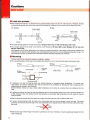
a When bending the lead wire, it is important not to apply excessive pressure to the root of the lead wire. Therefore, the lead
wire should be secured close to the case and bent (not twisted) at a distance 3 mm or more from the body of the fuse.
sF,/sM
Type
3 mm or
more
D6 Type
Secured
o The tensile strength applied to the lead wire should be SF-type: 49N or Iess and SM- and D6-types: 9.8N or less.
. The strength applied to the body of the thermal cutoff should be SF-type:98N or less, SM-type:49 N or less, and
D6-type:4.9N or less.
With regards to the SF-type, deformation of the case may change the location of the sliding contact during operation and
could lead to the thermal cutoff operating only at temperatures lower than the normal operating temperature range. The
thermal cutoff may also not operate even if the thermal cutoff's operating temperature is exceeded.
I
.
Mounting
Thermal cutoff can be mounted by soldering, caulking or welding.
The connecting position at the lead of resin-sealed side should be 5 mm or more from the body of the thermal cutoff.
SF Type
SM Type
t-
t--l
I
D6 Type
5 mm or more
u,
I
l\
I \
5 mm or more
connecting
\
Posltron
5 mm or more
o lf soldering, note that the thermal cutoff
may function because of excessive solder temperature. To prevent such
malfunctions, for example, holding the lead near the case with a tool is effective for allowing the heat to escape and the
soldering should be done in short intervals.
Another effective method is to use a lower solder temperature and to solder at a location that is at a distance from the
case.
o lf caulking or welding, be careful to keep the
resistance value of the connecting section low. lf the connecting section has
a high resistance value, the passing current may generate an abnormally high temperature that will cause the thermal
cutoff to operate.
a After mounting the thermal cutoff, pe careful not to apply force that may pull, push or twist the lead wires.
o lf using a SF-type-thermal
cutoff, the lead on the resin-sealed side must not be allowed to touch the case. This would
cause the currentlo tlow ftorn the lead on the resin.sealed side to the opposite lead so that the thermal cutoff cannot open
the circuit.
a Note that the body of the SF-type is the same in potential as the circuit. Therefore, it must be electrieally isolated from the
other metallic part.
25