1
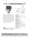
Scientific Production Company “Doza”
DOSIMETER/RADIOMETER DKS-96
User Manual
TE1.415313.003RE
Cont ent
1 Description and operation of dosimeter/radiometer ………….………………….…..…
1.1 Functionality of dosimeter/radiometer ……………………………………...…...…
1.2 Technical characteristics ………………………………………………...…………
1.3 Configuration ………………………………………………………………………
1.4 Design and operation of the dosimeter/radiometer ……..…...…………………..…
1.5 Marking and sealing ………………………………………..………………………
1.6 Packing …………………………………………………………………………..…
2 Description and operation of dosimeter/radiometer parts ………….………………..…
2.1 General information …………………………………………………………..……
2.2 Operation …………………………………………………………………………...
3 Intended use ……………………………………………………………………………
3.1 Operational limitations ………………………………………………………..……
3.2 Preparation of the dosimeter/radiometer for use ………….……………………..…
3.3 Use of the dosimeter/radiometer ……………………………………….………..…
3.3.1 Turning on/off ……………………….…………………………………...………
3.3.2 Measuring the background level ……………………………………………...….
3.4 Operation of the dosimeter/radiometer in "Measurement" mode …………...…..…
3.4.1 Using the control unit buttons in "Measurement" mode …….…………...………
3.4.2 Performing measurements in "Measurement" mode ………………………..……
3.5 Operation of the dosimeter/radiometer in "Settings" mode …………..……………
3.5.1 Using the control unit buttons in "Settings" mode ………………………….……
3.5.2 General information ………………………………………………………….…..
3.5.3 Configuring basic and advanced functions of "Measurement" mode ……………
3.5.4 "Configuration" menu ……………………………………………………………
3.5.5 "Alarm thresholds" menu …………………………………..………………….…
3.5.6 "Algorithm" menu …………………………………………………………....…..
3.5.7 "Coefficients" menu …………………………………………………….…..……
3.5.8 "Help" menu …………………………………………………………….….……
3.6 Connecting dosimeter/radiometer to PC ………………………………….…….…
3.7 Adjustment of dosimeter/radiometer ……………………………………..……..…
4 Maintenance ……………………………………………….……………………...……
4.1 General notes …………………………………………………………..……...……
4.2 Safety precautions …………………………………………………...…………..…
4.3 Maintenance routine …………………………………………………………..……
5 Calibration ……………………..……………………...…….…………………….……
6 Routine repairs …………………………………………………………………..……..
7 Storage ………………………………………………………………………..……..….
8 Transportation ……………………………………………………….…..…………......
9 Disposal …………………………………………………………………...………...….
Appendices are included in a separate document TE1.415313.003RE1
TE1.415313.003RE
2
3
3
3
12
13
17
17
17
17
17
23
23
23
23
23
25
25
25
28
31
31
31
32
35
39
40
41
41
41
44
44
44
44
45
45
45
46
46
46
This User Manual contains information on design and principle of operation of
dosimeters/radiometers DKS-96. The User Manual contains basic specifications and features, as well
as other information necessary for using the full range of technical possibilities of this product.
In the process of manufacturing dosimeters/radiometers DKS-96, their electric circuit, program
of operation or design can be modified without affecting the technical and metrological characteristics;
therefore such modifications may not be mentioned in this User Manual.
1 DESCRIPTION AND OPERATION OF DOSIMETER/RADIOMETER
1.1 Functionality of dosimeter/radiometer
1.1.1 Dosimeters/radiometers DKS-96 TE1.415313.003 (hereinafter – dosimeters/radiometers),
depending on the type of detector unit connected, provide measurement:
* 10 of continuous and pulsed X-ray and gamma radiation
- ambient dose equivalent rate
(hereinafter – ADER);
- ambient dose equivalent * 10 of continuous and pulsed X-ray and gamma radiation
(hereinafter – ADE);
* 10 of neutron radiation (hereinafter – ADER);
- ambient dose equivalent rate
- ambient dose equivalent * 10 of neutron radiation (hereinafter – ADE);
of gamma radiation (hereinafter – EDR);
- exposure dose rate Х
- alpha particle flux density;
- beta particle flux density;
- gamma photon flux density;
- flux density of neutrons;
- flux of gamma photons.
1.1.2 Dosimeters/radiometers are used in dosimetry services at nuclear power industry
facilities, at medical, scientific and other institutions, both standalone and as part of automated
radiation monitoring systems for the following tasks:
- operation and periodic monitoring of the radiation environment;
- measurement of surface contamination with alpha-, beta-, gamma- and neutron-emitting
substances;
- search and location of ionizing radiation sources;
- measurement of gamma photons flux and exposure dose rate of gamma radiation in wells and
liquid media.
- measurement of radioactive contamination of scrap metal;
- radiation surveys at prospective construction sites;
- at customs check-point for the inspection of vehicles and cargo.
Dosimeters/radiometers can be connected to a personal computer via cable adapter PI-03
(RS-232 – USB) when using control units UIK-05/UIK-05-01, UIK-06 and interface RS-485/RS-422
when using control unit UIK-07.
Dosimeters/radiometers can be used for radiation surveys with georeferencing in conjunction
with the global positioning system (GPS) sensor.
1.2 Technical characteristics
1.2.1 Basic metrological characteristics of dosimeters/radiometers for measurements of
alpha particle flux density
1.2.1.1 Basic metrological characteristics of dosimeters/radiometers for measurements of alpha
particle flux density are shown in Table 1.1.
TE1.415313.003RE
3
Table 1.1
Detector
unit
Measurement
range,
min-1·cm-2
BDZA-96
BDZA-96b
BDZA-96m
BDZA-96s
BDZA-96t
BDPS-96
0.1 to 1·104
0.1 to 2·103
0.1 to 1·105
0.1 to 5·104
0.1 to 1·106
0.2 to 1·104
Maximum permissible
basic relative error, %
±(20 +5/Ax),
where Ax – dimensionless
quantity that is
numerically equal to the
measured value of flux
density in min-1·cm-2
Intrinsic
background,
min-1·cm-2,
not more than
0.3
1.0
0.2
0.2
0.1
0.2
detection efficiency of
alpha radiation,
not less than, %
239
238
Pu 234U
U
42
25
15
42
31
21
50
30
18
45
25
15
45
32
30
45
25
15
Not es
1 Maximum permissible basic relative errors are normalized values for sources with radionuclide 239Pu.
2 According to customer's option, dosimeters/radiometers can be adapted to measure alpha particle flux density
with the above metrological characteristics for sources with radionuclides 234U and 238U.
3 The level of intrinsic background is normalized for the level of external gamma background not exceeding
0,2 μSv·h-1.
1.2.1.2 Dosimeters/radiometers are resistant to background gamma radiation with maximum
ADER when using detector units:
- BDZA-96b …………………….………………………….…….….…….…….. 0.01 mSv·h-1;
- BDZA-96, BDZA-96m, BDZA-96s, BDPS-96 …….…...……….……………… 1.0 mSv·h-1 ;
- BDZA-96t ……………………………………………………….…...….……. 100.0 mSv·h-1,
under the above conditions the measurement error of alpha particle flux density does not exceed the
values of basic relative error specified in 1.2.1.1.
1.2.1.3 Dosimeters/radiometers with detector unit BDZA-96t are resistant to background neutron
radiation with ADER up to 500 μSv·h-1, under these conditions the measurement error of alpha particle
flux density does not exceed the values of basic relative error specified in 1.2.1.1.
1.2.2 Basic metrological characteristics of dosimeters/radiometers for measurements of beta
particle flux density
1.2.2.1 Basic metrological characteristics of dosimeters/radiometers for measurements of beta
particle flux density are shown in Table 1.2.
Table 1.2
Detector
unit
BDZB-96
BDZB-96b
BDZB-96s
BDZB-99
BDKS-96s
BDPS-96
Measureme
nt range,
min-1·cm-2
Maximum
permissible basic
relative error, %
10 to 1·105 ±(20+200/Ax),
3 to 1·104 where Ax –
10 to 1·105 dimensionless
20 to 1·104 quantity that is
numerically equal to
10 to 3·104
5
10 to 1·10
the measured value
of flux density in
min-1·cm-2
Energy range of
detected
radiation, MeV
Intrinsic
background,
min-1·cm-2
Detection
efficiency for beta
radiation, not less
than, %
90
Sr+90Y
204
Tl
14
C
0.3 to 3.0
0.12 to 3.0
0.12 to 3.0
0.12 to 3.0
0.12 to 3.0
20.0
15.0
15.0
30.0
-
25
40
46
45
48
16
10
20
10
3
3
3
0.3 to 3.0
20
25
-
-
Not es
1 Maximum permissible basic relative errors are normalized values for sources with radionuclide 90Sr + 90Y.
2 The level of intrinsic background is normalized for the level of external gamma background not exceeding
0,2 μSv·h-1.
TE1.415313.003RE
4
1.2.2.2 Dosimeters/radiometers with detector unit BDKS-96s are resistant to background
gamma radiation with ADER up to 50 μSv·h-1, under these conditions the measurement error beta
particle flux density does not exceed the values of basic relative error specified in 1.2.2.1.
1.2.3 Basic metrological characteristics of dosimeters/radiometers for measurements
of X-ray and gamma radiation
1.2.3.1 Basic metrological characteristics of dosimeters/radiometers for measurements of X-ray
and gamma radiation are shown in Tables 1.3 and 1.4.
Table 1.3
Detector
unit
Measurement
range ADE
Measurement
range ADER
Maximum permissible basic
relative error, %
Anisotropy,
%
±(15+6/Ax),
BDKS-96,
BDKS-96b
from 0.1 μSv
to 10.0 Sv
from 0.1 μSv·h-1
to 1.0 Sv·h-1
BDKS-96s
from 0.1 μSv
to 10.0 mSv
from 0.1 μSv·h-1
to 1.0 mSv·h-1
where Ax – dimensionless quantity that is
numerically equal to the measured value of
ADE in μSv or ADER in μSv·h-1 for low
subrange and in mSv or mSv·h-1 for high
subrange, accordingly
±25
±(20+2/Ax),
where Ax – dimensionless quantity that is
numerically equal to the measured value of
ADE in μSv or ADER in μSv·h-1
±35
±(20+2/Ax),
BDMG-96
BDVG-96
BDPG-96
BDPG-96m
from 0.1 μSv
to 10.0 Sv
-
from 0.1 μSv·h-1
to 10.0 Sv·h-1
where Ax – dimensionless quantity that is
numerically equal to the measured value of
ADE in μSv or ADER in μSv·h-1 for low
subrange and in mSv or mSv·h-1 for high
subrange, accordingly
0.1 to 30,0 μSv·h-1
0.1 to 100 μSv·h-1
0.1 to 300 μSv·h-1
±13
±13
±13
±25
±35
±35
±35
Not es
1 Maximum permissible basic relative errors of dosimeters/radiometers with detector units BDVG-96, BDPG96 or BDPG-96m, are normalized values for sources with radionuclide 137Cs.
2 Dosimeters/radiometers with detector units BDVG-96, BDPG-96 or BDPG-96m, are recommended for the
monitoring of relative changes in the radiation environment only.
3 Anisotropy of detector units BDVG-96, BDKS-96, BDKS-96b, BDMG-96, BDPG-96 with reference to
radionuclide 137Cs is shown in the Appendix A.
4 Range of readings of dosimeters/radiometers with detector units:
- BDVG-96 …………………………………………………..……… from 0.03 to 36,0 μSv·h-1;
- BDPG-96 ………………………………………………………….. from 0.05 to 120 μSv·h-1;
- BDPG-96m ……………………………….………………………... from 0.05 to 360 μSv·h-1.
TE1.415313.003RE
5
Table 1.4
Detector unit
BDKS-96,
BDKS-96b
BDKS-96s
BDMG-96
BDVG-96
BDPG-96
BDPG-96m
Energy range of detected
radiation
Energy dependence, %
from 15 to 25 keV
±45
from 25 to 1250 keV
from +20 to minus 30
from 1.25 to 10 MeV
±15
from 0.05 to 3,0 MeV
from 0.05 to 3,0 MeV
not standardized
not standardized
not standardized
±30
±30
not standardized
not standardized
not standardized
Energy threshold of
detection, keV
20
50
50
Not e – Typical energy dependence of detector units BDKS-96, BDVG-96, BDPG-96 and BDPG-96m with
reference to radionuclide 137Cs is shown in the Appendix B.
1.2.3.2 Dosimeters/radiometers with detector units BDKS-96, BDKS-96b provide measurement
of ADER and ADE of pulsed X-ray and gamma radiation with the parameters given in Table 1.5.
Table 1.5
Measurement
subrange
High
Low
Parameters
of pulsed radiation
Frequency, s-1
NMT 1
1 to 10
more than 10
NMT 1
1 to 10
more than 10
Limiting values of measurands
Pulse duration
NLT0.3 ms
from 0.3 ms to 0.01 µs
NMT 0.01µs
NLT0.3 ms
from 0.3 ms to 0.01µs
NMT 0.01µs
ADER, Sv·s-1
NMT 1.0
NMT 5.0
*
NMT 0.01
NMT 0,05
*
ADE in a pulse, μSv
*
*
NMT 0,05
*
*
NMT 0,0005
* ADE in a pulse calculated as the product of ADER and pulse duration
1.2.3.3 Dosimeters/radiometers provide measurement of gamma photon flux density in the range:
- with detector unit BDVG-96 …………….…………….…………….….… 4 to 2000 s-1·cm-2 ;
- with detector unit BDPG-96 ………….……………..…………………… 10 to 8000 s-1·cm-2;
- with detector unit BDPG-96m ………………………….….…………… 10 to 24000 s-1·cm-2.
1.2.3.4 Maximum permissible basic relative error of gamma photons flux density
measurements …………………………………………………………………………….……... ±13 %.
1.2.3.5 Dosimeters/radiometers with detector unit BDKG-96 provide measurement of EDR
of gamma radiation with parameters listed in Table1.6.
Table 1.6
Detector
unit
Measurement
range exposure
dose rate, µR·h-1
Maximum
permissible
basic relative
error, %
Sensitivity,
s per 1 µR·h-1
Anisotropy,
%
Energy threshold
of gamma radiation
detection, keV
BDKG-96
5 to 2·104
±30
2.0 ±0.4
±45
100
-1
Not es
1 Maximum permissible basic relative errors are normalized values for sources with radionuclide 137Cs.
2 Anisotropy of the detector unit BDKG-96 with reference to radionuclide 137Cs is shown in the Appendix A.
TE1.415313.003RE
6
1.2.3.6 Dosimeters/radiometers with detector unit BDKG-96 provide measurement gamma
photons flux in the range from 20 to 80000 photon·s-1 (sensitivity (0.5 ±0.15) s-1 per 1 photon·s-1).
1.2.3.7 Maximum permissible basic relative error of gamma photons flux
measurements ……………………………………………………………………………..…… ±30 %.
1.2.4 Basic metrological characteristics of dosimeters/radiometers for measurements
of neutron radiation
1.2.4.1 Basic metrological characteristics of dosimeters/radiometers for measurements
of neutron radiation are shown in Tables 1.7, 1.8.
Table 1.7
Detector
unit
Measurement range ADE Measurement range ADER
BDMN-96
from 0.1 μSv to 1.0 Sv
Limits of permissible basic
relative error, %
±(25+6/Ax),
from 0.1 μSv·h-1
to 0.1 Sv·h-1
where Ax – dimensionless quantity
that is numerically equal to the
measured value of ADER in μSv·h-1
or ADE in μSv
-1
where Ax – dimensionless quantity
that is numerically equal to the
measured value of ADER in μSv·h-1
or ADE in μSv
±(25+5/Ax),
BDKN-96
from 0.1 μSv to 1.0 Sv
from 0.1 μSv·h
to 0.1 Sv·h-1
Not e - ADE and ADER measurement ranges, limits of basic relative error for neutron radiation measurements
by dosimeters/radiometers with detector unit BDKN-96 are normalized for Pu-α-Be source.
Table 1.8
Detector unit
Energy range of detected radiation
BDMN-96
BDKN-96
from 0.025 eV to 10.0 MeV
from 0.025 eV to 14.0 MeV
Energy dependence,
%
±40
±40
Anisotropy, %
±30
±30
Not e – The energy dependence of detector units BDMN-96, BDKN-96 is normalized for typical neutron spectra
with reference to Pu-α-Be source.
1.2.4.2 Dosimeters/radiometers with detector unit BDKN-96 provide measurement of flux
density of neutrons from Pu-α-Be source in the range ……………….………………. 1 to 104 s-1·cm-2.
1.2.4.3 Maximum permissible basic relative error of Pu-α-Be source neutrons flux density
measurements using dosimeters/radiometers with detector unit BDKN-96 …… ±(25 +5/Ax) %, where
Ax – dimensionless quantity that is numerically equal to the measured value of flux density of
neutrons in s-1 ·cm-2 .
1.2.4.4 Dosimeters/radiometers with detector unit BDKN-96 are resistant to background
gamma radiation with ADER up to 1.0 Sv·h-1 .
Limits of complementary error of ADER of neutron radiation measurements under conditions
of background gamma radiation with ADER up to 1.0 Sv·h-1 relative to measurement results obtained
at ADER of neutron radiation 1.0 mSv·h-1 …………………………..…………………………… ±10 %.
1.2.5 Basic technical characteristics of dosimeters/radiometers
1.2.5.1 Warm-up time of dosimeters/radiometers with detector units of any type, except
BDKS-96, is not more than ………………………………………………………….…………… 1 min.
Warm-up time of dosimeters/radiometers with detector unit BDKS-96 …………………15 min.
TE1.415313.003RE
7
1.2.5.2 Continuous operation time of dosimeters/radiometers from a fully charged (fresh)
batteries in normal conditions, depending on the type of control unit and the type of connected detector
unit is shown in the Table 1.9.
Table 1.9 – Continuous operation time of dosimeters/radiometers
Continuous operation time, h
BDZA-96, BDZA-96b, BDZA-96s,
BDZA-96m, BDZA-96t, BDZB-96,
BDZB-96b, BDZB-99, BDZB-96s,
BDPG-96, BDPG-96m, BDVG-96,
BDMN-96
BDKG-96, BDPS-96
BDMG-96
BDKS-96, BDKS-96b
BDKS-96s
BDKN-96
DKS-96-05
(UIK-05)
DKS-96-05-01
(UIK-05-01)
DKS-96-06
(UIK-06)
150.0
100.0
40.0
120.0
200.0
50.0
300.0
70.0
80.0
140.0
35.0
210.0
50.0
30.0
50.0
10.0
75.0
20.0
DKS-96-07
(UIK-07)
At least 2 hours when powered
from built-in batteries in the
absence of external power
supply.
Unlimited when powered from
an external source.
Type of detector unit
1.2.5.3 Instability of dosimeters/radiometers readings during 10 hours of continous operation
relative to the average value of readings during this interval does not exceed …………………. ±10 %.
1.2.5.4 Power supply of dosimeters/radiometers is provided as follows:
- control unit UIK-05 with power module PNN-02-02: four C (R14) type cells with total
nominal voltage ............................................................................................................................. 6.0 V;
- control unit UIK-05-01 with power module PNN-02-03: four batteries of AA type with
capacity not less than 2100 mA·h and total nominal voltage ........................................................ 6.0 V;
- control unit UIK-06: three batteries of AA type with capacity not less than 1000 mA·h s and
nominal voltage .............................................................................................................................. 4.5 V;
- control unit UIK-07:
1) mains power adapter BPS-06 with voltage ............................................................ 9 – 12 V;
2) DC source with nominal voltage .................................................................................. 24 V;
3) four built-in batteries of AA type with capacity 2100 mAh with nominal voltage 6 V backup emergency power supply.
Not e – Power supply from built-in batteries shall not be used as substitute of usual power supply, it supports
operation of UIK-07 unit for not more than 2 hours.
1.2.5.5 Dosimeters/radiometers are resistant to changes in supply voltage:
- control units UIK-05, UIK-05-01 ..................................................................... +6.0 to +3.9 V;
- control unit UIK-06 .......................................................................................... +4.5 to +2.9 V;
- control unit UIK-07 when powered by an external DC source ...................... +9.0 to +36.0 V.
Limits of complementary measurement errors for all measurands due to supply voltage
deviation from the nominal value ................................................................................................. ±5 %.
1.2.5.6 Current consumed by dosimeter/radiometer DKS-96-07 from an external DC source
with nominal voltage is not more than ......................................................................................... 10 mA.
Power consumption of dosimeter/radiometer DKS-96-07 when powered from AC
mains 220 V, 50 Hz, not more than ............................................................................................... 20 VA.
1.2.5.7 Charging of batteries of UIK-05-01 and UIK-06 units is provided using charger
ZU-02S/ZU-06S.
1.2.5.7.1 The built-in batteries of control unit UIK-07 are charged automatically when the unit
is connected to power source.
1.2.5.7.2 Power supply of charger ZU-02S, power adapter BPS-06 and signalling device
2 , 5
OSS-01 is provided from single-phase AC with voltage 220 22
33 V and frequency 50 2, 5 Hz.
TE1.415313.003RE
8
1.2.5.7.3 Power supply of charger ZU-06S is provided from the vehicle electrical system
with voltage ......................................................................................................................... 12 V or 24 V.
1.2.5.8 During operation dosimeters/radiometers automatically record measurements results
in non-volatile memory.
The memory is capable to store information about 2000 measurement results and allows
viewing of data on the display or transmission of data to personal computer using
the "TETRA_Reporter" software (if this software is included in the purchase contract).
1.2.5.9 Alarm thresholds can be set by operator separately for each modification of the
dosimeter/radiometer, each measuring channel and each measurement subrange.
1.2.5.10 Dosimeters/radiometers provide an audible alarm on exceeding the preset alarm
threshold, audible signals accompanying pulses generated by ionizing particles or photons in the
detector, and an audible signal after completion of the measuring process.
Dosimeters/radiometers DKS-96-07 generate light and audible signals when any of the alarm
thresholds is exceeded and control signals for general purpose signalling device OSS-01.
1.2.5.11 The algorithm of dosimeters/radiometers performs the following functions:
- automatic identification of connected detector unit and displaying of the type of detector and
corresponding measurement unit;
- automatic subtraction (compensation) of intrinsic or external background from the
measurement result, only for detector units that can measure and compensate the background;
- automatic monitoring of supply voltage and display of current supply voltage: a fully
charged battery is depicted as
, while a fully discharged battery as
;
- automatic monitoring of supply voltage drop down to 3.9 V for UIK-05/UIK-05-01; 2.9 V for UIK-06, 3.9 V for UIK-07; when this voltage drops to the above values the display will indicate
a warning "Battery discharged" or generate a series of three beeps and then the dosimeter/radiometer
turns off;
- automatic maintaining of current date and time starting from installation of batteries or
cells into the control unit and until their removal or disconnecting of power supply module
PNN-02-02/PNN-02-03 from the unit; when the control unit is turned on after replacing the batteries or
cells or after power failure the unit asks the operator to input current date and time;
- automatic display of current date and time.
- auto-saving of measurements results in the archive if "Autosave" mode was selected or in
manual mode.
1.2.5.12 Dosimeters/radiometers may be used as monitoring points in the automated radiation
monitoring system supporting data transmission protocol DiBUS.
1.2.5.13 Dosimeters/radiometers may be used for radiation survey of the land territory with
georeferencing in conjunction with the global positioning system (GPS) sensor.
For receiving information from GPS sensor RS-232 interface and software protocol
NMEA 0183 (version 2.0) are used.
Not e – For operating conditions of GPS sensors refer to the documentation supplied by the manufacturer.
1.2.5.14 Operating conditions of techical components of dosimeters/radiometers:
1) detector units of all types, control units of all types, interface device US-96, signalling
device OSS-01, charger ZU-06S, unit BPS-06:
- temperature range:
measurements with indication of results on the display ...................... from minus 20 to +50 °C,
measurements without indication of results on the display ................ from minus 40 to +50 °C,
- relative humidity limit ...................................................................................... 98 % at +35 C,
- atmospheric pressure .................................................................................... 84.0 to 106.7 kPa,
- content of corrosive agents in ambient air, atmosphere types ..................................... I, II, III;
2) interface converter PI-02 of charger ZU-02S:
- temperature range ................................................................................................... 0 to +50 °C,
TE1.415313.003RE
9
- relative humidity limit ..................................................................................... 95 % at +35 C,
and lower temperatures without condensation,
- atmospheric pressure in the range ............................................................... 84.0 to 106.7 kPa,
- content of corrosive agents in ambient air, atmosphere types ............................................I, II.
1.2.5.15 Limits of complementary measurement errors for all measurands:
- due to deviation of ambient air temperature from normal conditions, per each 10 C – ±10 %;
- due to increasing of the ambient air humidity up to 98 % at +35 C .......................... ±10 %.
1.2.5.16 Dosimeters/radiometers are resistant to sinusoidal vibrations in the frequency range
from 10 to 50 Hz with displacement amplitude 0.35 mm.
1.2.5.17 Dosimeters/radiometers DKS-96-05, DKS-96-05-01, DKS-96-06 are shockproof and
withstand falling from height not more than 750 mm.
1.2.5.18 In terms of earthquake resistance dosimeters/radiometers DKS-96-07 are classified as
category II devices according to Russian rules NP-031-01 "Design code for earthquake-resistant
nuclear power plants" and meets the requirements of Russian regulations RD-25-818 "General
requirements and testing procedures of the seismic stability of instruments and automation equipment
supplied for the nuclear power plants": group A according to place of installation; version 2 according
to functional purpose, for seismic load of up to 7 points by MSK-64 scale at the level from 70 m to 30 m
relative to zero level.
After seismic impact with the above parameters dosimeter/radiometer DKS-96-07 meets the
requirements of sections 1.2.1.1, 1.2.2.1, 1.2.3.1, 1.2.3.4, 1.2.3.7, 1.2.4.1, 1.2.4.3 during the entire
service life under specified operating conditions.
1.2.5.19 The degree of protection provided by unit shells, against penetration of solid objects
and water:
- interface converter PI-02 …………………………………………………….…...….…. IP30;
- charger ZU-02S, power adapter BPS-06 ………………………………………...…..…. IP40;
- control units UIK-05, UIK-05-01, UIK-06, units BDZA-96, BDZA-96b, BDZA-96m,
BDZA-96s, BDZA-96t, BDZB-96, BDZB-96b, BDZB-96s, BDZB-99, BDKS-96s, BDPS-96,
charger ZU-06S …………………………………………………………...………………….….... IP54;
- detector units BDVG-96, BDKS-96, BDKS-96b, BDMG-96, BDMN-96, BDPG-96,
BDPG-96m, BDKN-96, control unit UIK-07, signalling device OSS-01, device US-96 ..…….… IP65;
- unit BDKG-96 ………………………………………………………….…….........…… IP68.
1.2.5.20 In term of importance for safety, dosimeters/radiometers are classified as normal
operation elements, safety class 4N (classification as per the Russian standard OPB-88/97).
1.2.5.21 Dosimeters/radiometers are resistant to electromagnetic disturbances in compliance with
IEC 1000-4-8-93, IEC 1000-4-9-93, IEC 61000-4-2-95, IEC 61000-4-3:2006, IEC 61000-4-4:2004,
IEC 61000-4-5-95, IEC 61000-4-6-96, IEC 61000-4-11:2004, IEC 61000-4-12-95, IEC 61000-4-13:2002,
IEC 61000-4-14-99 and IEC 61000-4-28-99 and conform to electromagnetic compatibility standards
set by IEC 61000-3-2:2005, IEC 61000-3-3:2008, CISPR 22:2006 for Class A equipment.
Electromagnetic interference does not change the dosimeters/radiometers readings by more
than ±10 %.
1.2.5.22 Dosimeters/radiometers with detector units BDVG-96, BDKG-96, BDKS-96, BDKS96b, BDMG-96, BDPG-96, BDPG-96m in ADER/ADE of gamma radiation measurement mode or
with detector unit BDKG-96 in EDR of gamma radiation measurement mode are resistant to
background radiation of fast neutrons with energy up to 10 MeV and ADER numerically equal to the
value of ADER/EDR of measured gamma radiation.
Limits of complementary measurement error due to exposure to background fast neutrons ±10 %.
1.2.5.23 Dosimeters/radiometers with detector units BDVG-96, BDKG-96, BDKS-96,
BDKS-96b, BDMG-96, BDPG-96 in ADER/ADE of gamma radiation measurement mode or with
detector unit BDKG-96 in EDR of gamma radiation measurement mode are resistant to background
beta radiation from the 90Sr+90Y source with ADER numerically equal to the value of ADER/EDR
of measured gamma radiation.
TE1.415313.003RE
10
Limits of complementary measurement error due to exposure to background beta
radiation …………………………………………….………………………….…………..…… ±10 %.
1.2.5.24 Dosimeters/radiometers maintain operability after a short, less than 5 minutes,
controlled exposure to ionizing radiation with the level 10-fold higher than the upper limit
of measurement range.
After overload, dosimeters/radiometers maintain operability and are capable to work withing
specified limits of basic relative measurement error.
1.2.5.25 Dosimeters/radiometers are protected against electric shock in compliance with
IEC 61010-1:2001.
1.2.5.26 Dosimeters/radiometers are fire-safe devices with fire probability of causing fire
not more than 10-6 year-1.
1.2.5.27 Dosimeters/radiometers are resistant to exposure to 5 % citric acid solution in rectified
ethyl alcohol.
1.2.5.28 Dimensions and weight of techical components of dosimeters/radiometers are listed in
Table 1.10.
Table 1.10
Component
Control unit UIK-05
Control unit UIK-06
Control unit UIK-07
Detector unit BDZA-96
Detector unit BDZA-96b
Detector unit BDZA-96m
Detector unit BDZA-96s
Detector unit BDZA-96t
Detector unit BDZB-96
Detector unit BDZB-96b
Detector unit BDZB-96s
Detector unit BDZB-99
Detector unit BDPS-96
Detector unit BDKS-96
Detector unit BDKS-96b
Detector unit BDKS-96s
Detector unit BDMG-96
Detector unit BDPG-96
Detector unit BDPG-96m
Detector unit BDVG-96
Detector unit BDKG-96
Detector unit BDKN-96
Detector unit BDMN-96
Spherical moderator
Interface device US-96:
interface assembly US-96-1, US-96-2
Signalling device OSS-01
AC mains adapter BPS-06
Charger ZU-02S
Charger ZU-06S
Extension pole
Pole for detector unit
Pole for detector unit
Dimensions, mm
210×100×85
165×80×50
160×133×85
Ø130×240
Ø230×290
Ø65×240
Ø90×240
Ø50×60
Ø90×230
150×200×110
Ø65×65
Ø88×80
Ø88×280
Ø72×265
Ø60×250
Ø80×80
Ø40×250
50×190×480
Ø35×320
Ø88×400
Ø38×535
295×142×100
Ø54×200
Ø245
Weight, kg
0.9
0.4
1.5
0.9
4.0
0.9
1.0
0.15
0.9
1.5
0.3
0.4
1.2
1.8
0.85
0.35
0.5
1.0
0.5
2.0
3.6
2.25
0.8
7.3
45×50×65
77×77×387
52×82×1000
80×80×50
Vehicle charger
Ø34×860
Ø74×1600
Ø74×3800
0.3
2.8
0.3
0.3
0.1
0.1
0.3
0.5
TE1.415313.003RE
11
1.2.5.29 Mean time before failure ………………….…………….… not less than 10 000 hours.
1.2.5.30 Mean life time ………………………………….……..……..…. not less than 10 years.
1.3 Configuration
1.3.1 Dosimeter/radiometer represents an instrument that consists of control unit and includes
one of the following detector units:
- detector unit BDZA-96 (basic version) with light protective screen for measurements
of alpha particle flux density;
- detector unit BDZA-96b (large) with light protective screen for measurements of alpha
particle flux density;
- detector unit BDZA-96s (medium) with light protective screen for measurements of alpha
particle flux density;
- detector unit BDZA-96m (small) with light protective screen for measurements of alpha
particle flux density;
- detector unit BDZA-96t (solid state) with light protective screen for measurements of alpha
particle flux density;
- detector unit BDZB-96 (basic version) with light protective screen for measurements of beta
particle flux density;
- detector unit BDZB-96b (large) for measurements of beta particle flux density;
- detector unit BDZB-99 (GM counter) for measurements of beta particle flux density;
- detector unit BDZB-96s (medium) for measurements of beta particle flux density;
- detector unit BDPS-96 with light protective screen for measurements of flux density
of alpha- and beta-particles;
- detector unit BDKS-96 for measurements of ambient dose equivalent and ambient dose
equivalent rate of continuous and pulsed X-ray and gamma radiation;
- detector unit BDKS-96b for measurements of ambient dose equivalent and ambient dose
equivalent rate of continuous and pulsed X-ray and gamma radiation;
- detector unit BDKS-96s for measurements of ambient dose equivalent and ambient dose
equivalent rate of continuous X-ray and gamma radiation, beta particle flux density;
- detector unit BDMG-96 for measurements of ambient dose equivalent and ambient dose
equivalent rate of continuous X-ray and gamma radiation;
- detector unit BDVG-96 (high sensitivity) for measurements of ambient dose equivalent rate
of continuous X-ray and gamma radiation and gamma photon flux density;
- detector unit BDPG-96 (survey) for measurements of ambient dose equivalent rate of
continuous X-ray and gamma radiation and gamma photon flux density;
- detector unit BDPG-96m (survey small) for measurements of ambient dose equivalent rate
of continuous X-ray and gamma radiation and gamma photon flux density;
- detector unit BDKG-96 (logging) for measurements of exposure dose rate of gamma
radiation and gamma photons flux;
- detector unit BDMN-96 with spherical moderator for measurements of ambient dose
equivalent and ambient dose equivalent rate of neutron radiation;
- detector unit BDKN-96 with cylindrical polyethylene moderator for measurements of
ambient dose equivalent, ambient dose equivalent rate of neutron radiation and flux density of
neutrons.
Not e - Letter designations of detector units contain information about the type of the detected radiation (the last
letter in the unit name) and/or about the design features of the unit (capital letter after "96" in the unit name).
Detector units, except detector unit BDKG-96, are supplied with connecting cable with
length 1.5 m.
Detector unit BDKG-96 is supplied with connecting cable with length 10 m and matching
device. Customer can order connecting cable with length from 5 m to 1000 m supplied with matching
device.
TE1.415313.003RE
12
The number of detector units included in the delivery set, not more than one unit of each type,
shall be determined by the consumer based on measurement tasks.
1.3.2 Dosimeters/radiometers can be equipped with the following control units:
- portable control unit UIK-05 with electric cell power supply module PNN-02-02;
- portable control unit UIK-05-01 with battery power supply module PNN-02-03;
- portable control unit UIK-06;
- stationary control unit UIK-07.
1.3.3 According to customer’s order the delivery set may include:
- connecting cable with length 4 m (except detector units BDKS-96 and BDKS-96b);
- connecting cable with length up to 20 m (except detector units BDKS-96 and BDKS-96b);
- connecting cable with length from 20 to 500 m;
- interface device US-96 if the delivery includes connecting cable 20 to 500 m;
- cable-adapter PI-03 for connecting control units UIK-05/UIK-05-01/UIK-06 to PC;
- extension poles of various length, belts to hang the unit on operator’s neck, wrist cuff
for operator comfort;
- interface converter PI-02 for connecting of control unit UIK-07 to PC;
- communication cable "UIK-07-Atlant" for connecting of control unit UIK-07 to PI-02;
- AC mains adapter BPS-06 to supply power to UIK-07 from AC mains 220 V, 50 Hz;
- charger ZU-02S for charging batteries in the power module PNN-02-03 of the UIK-05-01
unit and in the UIK-06 unit;
- vehicle charger ZU-06S for charging batteries in the power module PNN-02-03 of the
UIK-05-01 unit and in the UIK-06 unit;
- signalling device OSS-01 generating light and audible signals when connected to UIK-07;
- global positioning system sensor - for conducting geo-referenced radiation surveys;
- service software "TETRA_Checker" intended for output of measurement data to PC;
- service software "TETRA_Reporter" intended for reading data from the control unit’s
archive and generating reports based on these data in selected format (RTF, HTML, TXT), the
software can also be used to delete measurement information from archive.
1.4 Design and operation of the dosimeter/radiometer
1.4.1 In the design of detector units well-known methods were used as for converting the
energy of ionizing radiation into analog and digital electrical signals,as well as common circuit designs
of power supply, amplification and discrimination units, etc. The detectors used are scintillators, gasdischarge counters or semiconductor detectors. Measurement data are processed using formula
PK
N
1 NМ
(1.1)
where P – readings of the dosimeter/radiometer in appropriate units depending on the measurand;
K 1 / – conversion factor;
– sensitivity factor of the detector unit;
N – pulse rate, s-1;
M – "dead time", s.
Matching of metrological parameters of the dosimeter/radiometer to the values specified in
section 1.2 is ensured by determination and storing of sensitivity coefficients and dead time specific
for each of the detector units in non-volatile memory of control unit during calibration. If the detector
unit has two subranges (Low and High) or two measurement channels (gamma and beta), then the
values of sensitivity factors and "dead time" is determined separately for each subrange/channel and
each measured physical quantity (dose rate, flux density, count rate…).
TE1.415313.003RE
13
1.4.2 Software of the dosimeter/radiometer is stored to processor’s ROM, unauthorized
modification is not possible (14-digit password protection). The mechanisms of protection of the flash
memory data (sensitivity factors and constants) during read/write/erase operations and of separate
information area in the flash memory which contain device ID and software versions are implemented
by the manufacturer of control unit’s processor (Renesas company).
1.4.3 The software of the dosimeter/radiometer implements three algorithms of continuous
measurements of physical quantities characterizing ionizing radiation to be detected:
- "Fixed time";
- "Fixed tolerance";
- "Tracking".
1.4.3.1 Algorithm "Fixed time" provides a measurement resultequal to the current average
value within given interval. The range of available intervals (measurement time) is 3 to 9999 seconds.
Algorithm "Fixed time" starts automatically after turning on the dosimeter/radiometer; by default the
"Measurement" time is set to values shown in Table 1.12.
1.4.3.2 Algorithm "Fixed tolerance" provides a measurement result with default value of
uncertainty equal to 6 %. The uncertainty u (in percents) is calculated as follows:
u
2
100
N
(1.2)
where N is the number counts detected at this point.
The measurement process is completed after the detection of such number of counts (1111),
which provides an acceptable level of statistical error (uncertainty) or after expiration of user preset
interval (measurement time), in case during this interval the required number of counts is not detected.
If the interval is set to zero, then it is not limited in time.
The operator can stop the output of current measurement results at any time by pressing the
button , without interrupting the measurement process. The output of measurement information
resumes after pressing the button again.
1.4.3.3 Algorithm "Tracking" provides a measurement result equal to the arithmetic mean
calculated by the moving average method based on N measurement results with one second interval
each. The number of measurements N is determined by averaging period during which the control unit
detects the number of counts determined by the algorithm. The duration of averaging period depends
only on the dynamics of radiation environment and in the absence of significant changes may reach
200 seconds. If the number of counts detected in the averaging period differ from that in the previous
period by more than three sigma (standard deviations), than the measurement process automatically
restarts and readings are updated. When calculating the updated readings, previous measurement result
is not taken into account; that provides rapid response to changes in radiation environment. It is
recommended to use this algorithm only with detector units BDPG-96, BDPG-96m or BDVG-96.
1.4.3.4 All algorithms of the dosimeter/radiometer has "Autosave" function which is used to
automatically save measurements results in the archive which can be enabled or disabled.
Function "Stop after N meas" provides the possibility to perform a series of N measurements
and save measurement results in memory.
Parameters of algorithms and "Autosave" and "Stop after N meas" functions can be selected in
"Settings" mode under "Algorithm" menu item. Algorithms and "Settings" mode of the
dosimeter/radiometer are described in section 3.5; regarding "Measurement" mode – in section 3.3.1.
1.4.4 Dosimeter/radiometer operates in two modes:
- "Measurement" (main mode);
- "Settings" (auxiliary mode).
TE1.415313.003RE
14
To start any of the above modes, the dosimeter/radiometer must be turned off. Modes are
started as follows:
- pressing turns on the control unit in "Measurement" mode;
- pressing after pressing and holding turns on the control unit in "Settings" mode.
In each mode measured values can be viewed in information windows described in sections 3.4
and 3.5.
1.4.5 Dosimeter/radiometer is delivered with default settings:
- mode and allowed windows for the mode used are listed in Table 1.11;
- measurement unit: the main unit for this detector unit type as per Table 1.12;
- measurement algorithm: "Fixed time";
- measurement time: as per Table 1.12; for each detector unit the corresponding preset time
ensures that the measurement uncertainty is below 50 % at the lower limit of measurement range;
- alarm thresholds: zero;
- dynamic scale: OFF;
- work with archive of measurement results: not supported;
- autosave mode: disabled;
- parameter "N" of the "Stop after N meas." function: zero.
1.4.6 Default settings of the control unit allow measurements with optimal parameters. Types
of detector units that provide the possibility of background radiation compensation are listed in
Table 1.11.
Table 1.11
Background
Windows
Type of
Background
Windows available in
measurement
available in
detector unit
measurement
"Measurement" mode
time, s
"Settings" mode
BDZA-96
+
60
"Primary measurement"
BDZA-96b
+
30
"Primary measurement"
BDZA-96m
+
100
"Primary measurement"
BDZA-96s
+
100
"Primary measurement"
BDZA-96t
"Primary measurement"
BDZB-96
+
30
"Primary measurement"
"Threshold",
BDZB-96b
+
30
"Primary measurement"
"Archive"
BDZB-96s
+
30
"Primary measurement"
BDZB-99
+
30
"Primary measurement"
"Primary measurement";
100
BDPS-96
+
"Secondary measurement"
30
BDMN-96
"Primary measurement"; "Dose"
BDKN-96
"Primary measurement"; "Dose"
BDKS-96
+
30
"Primary measurement"; "Dose"
BDKS-96b
"Primary measurement"; "Dose"
"Primary measurement"; "Dose";
BDKS-96s
"Secondary measurement"
BDMG-96
"Primary measurement"; "Dose"
"Search",
"Primary measurement";
"Threshold",
BDPG-96
"Detection"
"Archive"
"Primary measurement";
BDPG-96m
"Detection"
"Primary measurement";
BDVG-96
"Detection"
BDKG-96
"Primary measurement"
TE1.415313.003RE
15
Typical values of sensitivity factors and "dead times" determined during manufacturing of the
dosimeter/radiometer are listed in Table 1.12.
Table 1.12
BDZA-96
BDZA-96b
BDZA-96m
BDZA-96s
BDZA-96t
BDZB-96
BDZB-96b
BDZB-96s
BDZB-99
BDPS-96
(alpha)
BDPS-96
(beta)
BDKS-96
(Low subr.)
BDKS-96
(High subr.)
BDKS-96b
(Low subr.)
BDKS-96b
(High subr.)
BDKS-96sbeta
BDKS-96sgamma
BDMG-96
(Low subr.)
BDMG-96
(High subr.)
BDPG-96
BDPG-96m
BDVG-96
BDKG-96
BDMN-96
BDKN-96
Basic unit
Additional
unit
Sensitiv.
factor
"Dead time",
Meas. time,
Algorithm
µs
s
min-1·cm-2
min-1·cm-2
min-1·cm-2
min-1·cm-2
min-1·cm-2
min-1·cm-2
min-1·cm-2
min-1·cm-2
min-1·cm-2
-
2.20e-0
5.00e-1
1.50e+1
5.0e-0
2.50e-0
8.00e-0
1.60e-0
9.00-0
4.00e-0
005.0
005.0
002.0
015.0
010.0
002.0
055.0
105.0
110.0
20
10
30
40
20
10
10
10
10
*
*
*
*
*
*
*
*
*
min-1·cm-2
-
5.0e-0
5.0
20
*
min-1·cm-2
-
7.0e-0
2.0
20
*
Sv/h, Sv
-
1.00e-7
000.5
10
-
Sv/h, Sv
-
1.00e-5
000.5
10
-
Sv/h, Sv
1.00e-7
001.0
10
-
Sv/h, Sv
2.00e-4
010.0
10
-
20
-
Fixed time
Type of
detector unit
Note
min-1·cm-2
-
8.0e-0
100.0
Sv/h, Sv
-
2.00e-7
100.0
20
-
Sv/h, Sv
-
2.00e-7
060.0
20
-
Sv/h, Sv
-
1.75e-4
040.0
20
-
Sv/h
Sv/h
Sv/h
R/h
Sv/h, Sv
Sv/h, Sv
-
s-1·cm-2
s-1·cm-2
s-1
·cm-2
photon·s-1
s-1·cm-2
2.00e-9
1.50e-1
4.00e-9
0.30e-0
4.00e-10
3.00e-2
5.20e-7
3.70e-0
2.45e-6
2.00e-7
1.56e-1
002.5
002.5
005.0
005.0
002.0
002.0
015.0
015.0
023.0
025.0
025.0
10
10
10
10
10
10
10
10
20
**
**
**
**
-
20
-
* For detector units BDZA and BDZB the measurement unit "Bq·cm-2" can be used after its selection in "Settings"
mode and proper calibration of the dosimeter/radiometer.
** For detector units BDPG and BDVG the use of additional units is possible after their selection in "Settings" mode.
TE1.415313.003RE
16
1.4.7 According to the results of subsequent calibrations of the dosimeter/radiometer equipped
with supplied detector unit(s) the sensitivity factors and "dead times" can be corrected in the "Settings"
mode.
1.5 Marking and sealing
1.5.1 The nameplate on the control unit contains the following information:
- trademark and name of the manufacturer (supplier);
- reference designation of the dosimeter/radiometer and control unit as per modification;
- works number according to the manufacturer's system of numeration;
- year of manufacture;
- approval mark of measurement instrument;
- ingress protection rating (IP).
1.5.2 The following markings are placed on the detector unit:
- trademark and name of the manufacturer (supplier);
- reference designation of the dosimeter/radiometer;
- reference designation of the detector unit;
- works number according to the manufacturer's system of numeration;
- year of manufacture;
- ingress protection rating (IP);
- made in Russia.
1.5.3 The location and method of fixing of the nameplate shall comply with the design
documentation.
1.5.4 Components of dosimeters/radiometers are sealed in accordance with the design
documentation.
1.6 Packing
1.6.1 Packing of dosimeters/radiometers shall comply with the design documentation and
ensures protection against ingress of atmospheric precipitations and aerosols, splashes of water, dust,
sand, solar ultra-violet radiation and also limits the ingress of water vapour and gases.
2 DESCRIPTION AND OPERATION OF DOSIMETER/RADIOMETER PARTS
2.1 General information
This section describes the structure and purpose of detector units, control units and devices of
the dosimeter/radiometer.
2.2 Operation
2.2.1 Detector units
The dosimeter/radiometer set may include detector units of any type listed in section 1.3.1, but
not more than one detector of each type. The reason is that the algorithm of dosimeter/radiometer
automatically recognizes the type of connected detector unit and uses calibration factors stored in
memory for detector units of particular type, but the units are not identified by their individual
numbers (for example, by serial numbers).
Detectors used in the detector units and features of their design are listed in Table 2.1.
TE1.415313.003RE
17
Table 2.1
Detector unit
Detector
2
BDZA-96
BDZA-96b
BDZA-96m
BDZA-96s
ZnS(Ag)
ZnS(Ag)
ZnS(Ag)
ZnS(Ag)
S = 70 cm
S = 300 cm2
S = 10 cm2
S = 30 cm2
BDZA-96t
Semiconductor detector
S = 5 cm2
BDZB-96
BDZB-96b
BDZB-96s
BDZB-99
BDPS-96
BDKS-96
BDKS-96b
BDKS-96s
BDMG-96
BDPG-96
BDPG-96m
BDVG-96
BDKG-96
BDKN-96
BDMN-96
PMT type
Detector size and design
Plastic scintillator
Counters Beta-5×2 pcs
Counter Beta-2
Counter SI-8B
Plastic scintillator +
ZnS(Ag)
Tissue-equivalent plastic
scintillator
Tissue-equivalent
plastic
scintillator
Counters: Beta-2, Beta-2m
Counters: SBM-20×2 pcs,
SI-34G×1 pcs
NaJ(Tl)
NaJ(Tl)
NaJ(Tl)
NaJ(Tl)
Proportional neutron counter
LiF with 6Li content 85% +
ZnS(Ag)
Notes
FEU-35-1
FEU-139
FEU-35-1
FEU-35-1
-
2
S = 28 cm
S = 80 cm2
S = 15 cm2
S = 30 cm2
FEU-35-1
-
S = 28 cm2
FEU-118
Ø45×20 mm, light
diaphragm with three fixed
positions: "COMP",
"mSv", "μSv"
FEU-118
(R980-A)
FEU
R1294A
-
Ø30×15 mm
S = 15 cm2
Ø25×40 mm
Ø18×30 mm
Ø63×63 mm
Ø18×30 mm
S = 5.0 cm2
FEU-35-1
FEU-67b
FEU-35-1
FEU-67B
Logging
FEU-35-1
Placed inside
moderator
-
Detector units for measurements of alpha- and beta-particles are equipped with protective plugs
which are placed on the surface of detectors to provide full absorption of relevant particles when the
background is measured and to protect the detector’s window during transportation. Measurements of
flux density of alpha- and beta-particles are carried out with protective plugs removed.
Detector units are connected to the control unit using connecting cable which is fixed in the
back part of the detector unit, through the connector of RS7 type.
2.2.2 Control units
2.2.2.1 Control units UIK-05 and UIK-05-01 have a metal shockproof body to which power
cell power supply module PNN-02-02 or battery power supply module PNN-02-03 is connected.
Connector for detector unit is located on the side of control units UIK-05 and UIK-05-01, the
power supply module has jack connector for headphones or for charger (in case of battery power
supply PNN-02-03).
The power supply module is connected to UIK-05/UIK-05-01 via connector (RS4TV type) and
fixed by two screws.
The front panel of the control unit is equipped with graphic display and control buttons.
TE1.415313.003RE
18
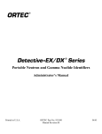
2.2.2.2 Control unit UIK-06 has a plastic shockproof body; batteries are located in the battery
compartment on the rear side of the control unit body, under the cover.
The front panel of the control unit is equipped with graphic display and control buttons.
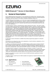
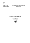
Portable control units are shown in Figure 2.1.
Control unit UIK-05/UIK-05-01
Control unit UIK-06
Figure 2.1 – Appearance of portable control units
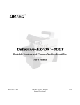
2.2.2.3 Stationary control unit UIK-07 is intended to be mounted on a vertical or horizontal
surface. This unit is functionally identical to units UIK-05, UIK-05-01 and UIK-06.
The front panel of the control unit is equipped with graphic display, control buttons, LED and
acoustic radiator, which provide audible and light signals when the measurement result exceeds preset
alarm threshold.
The four connectors on the side of the UIK-07 unit are the following:
- "BD" - for connection of detector unit;
- "LINE" - for connection of communication cable "UIK-07-Atlant" with information system or
PC through interface converter PI-02 or equivalent;
- "9 – 36 V" - for connection of power adapter BPS-06 or another DC voltage source;
- "OSS" - for connection of signalling device OSS-01 if it is included in the delivery set.
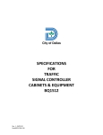
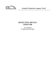
The appearance of control unit UIK-07 is shown in Figure 2.2; overall and mounting
dimensions are presented in Appendix C.
Figure 2.2 – Appearance of stationary control unit UIK-07
TE1.415313.003RE
19
Power supply of UIK-07 unit when it is disconnected from external source is provided from
built-in batteries. When power adapter BPS-06 or another power supply source is connected to the
control unit, batteries are charged automatically and their charged condition is maintained. It takes
approximately 12 hours to fully charge batteries.
2.2.2.4 All control units allow continuous monitoring of changes in the measured quantities by
readings presented on the display and by sounds generated by the units in the process of radiation
detection.
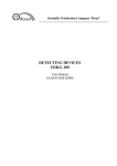
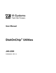
2.2.2.5 Description of the graphic display
The display can indicate letters, digits, signs and pictograms as shown in Figure 2.3.
Pictograms
Measurement
uncertainty
Analog
logarithmic
scale
Countdown of
measurement
time in seconds
Measurement unit
Reading
Current time
Figure 2.3
Pictograms are intended to indicate information about the dimension of measurement units,
current events and modes of the dosimeter/radiometer:
- ► or ▌▌ - indicates the current state of the dosimeter/radiometer: measurement process or
pause between the measuring cycles;
- L or H - indicates which Subrange is active: Low or High;
- α or β - indicates which type of radiation is measured by the detector unit BDPS-96;
- indicates the presence of pulse disturbances; this is an advices to repeate measurement;
- indicates that the sound is muted, if the sound is enabled, then in this place one of the
following pictograms is displayed: ↑ or ↓, or ↨, indicating possible options to adjust the frequency of
sound signals;
- indicates that measurement intrinsic and/or external background was not carried out (for
detector units requiring such measurement for automatic background compensation); during
background measurement this pictogram is blinking and after completion of such measurement it
disappears;
-
- indicates that current value of the main measurand exceeds the "Alarm" threshold;
- indicates that current value of additional measurand measured by detector unit
BDKS-96s (beta particle flux density) exceeds the "Beta" threshold;
-
- indicates that the measured ADE exceeds the "Dose" threshold;
- indicates charge condition of batteries or electric cell voltage.
TE1.415313.003RE
20
2.2.2.6 Description of controls
The control unit has the following multifunction buttons:
- button "ON";
- button "SELECTION";
- button "SOUND";
☼ - button "LIGHT";
/ΙΙ - button "DOWN/PAUSE" (hereinafter – );
/ - button "UP/NEXT WINDOW" (hereinafter – ).
In addition, combinations of button pressings start and cancel certain modes.
2.2.2.7 Hereinafter operator’s actions with buttons are denoted as follows:
☼ (single button symbol) - press the button for about 0.5 s;
☼☼ (double button symbol) – press and hold the button for about 1.5 s;
(two identical symbols divided by space) – successively press this button twice;
(two different symbols without space) - simultaneous pressing: press the second button
while pressing and holding the first button);
(three symbols, with space between the second symbol and the third symbol) - press
and hold the first button then press the second button twice.
Actions of the operator are accompanied by beeps or melody. Brief instructions for the operator
for using the control unit is presented in Appendix D.
2.2.2.8 With factory settings, the following combunations of buttons can be used:
- turn on, start measurement, cancel editing, go to the top-level menu (analog of
Esc/Cancel on a computer keyboard);
☼ - show help window;
- turn off;
☼ - turn on display backlight for 3 seconds / turn off display backlight;
☼☼ - turn on permanent backlight of display;
- turn the sound on/off;
- set alarm thresholds for current measurement window;
- pause / resume measurement cycle;
- set parameters of algorithm (for example, measurement time);
- increase the frequency of audible signals;
- decrease the frequency of audible signals;
– enable background measurement mode when using detector units for which
background measurements are possible for background compensation;
- switching between windows in which measurement results are displayed in operator
selected modes;
- manual activation of "High" subrange for two-channel detector units BDMG-96,
BDKS-96 and BDKS-96b;
- manual activation of "Low" subrange for two-channel detector units BDMG-96,
BDKS-96 and BDKS-96b;
- enable automatic switching of subranges (for detector units BDKS-96b and BDMG96 only ).
Adjustment of numerical values (date, time, factors, alarm thresholds) is provided through the
following actions: - move the cursor to the next character, - decrement the digit above the cursor,
- increment the digit above the cursor.
2.2.2.9 Dosimeter/radiometer can be used as a measuring device for average count rate when in
"Settings" mode the appropriate unit, s-1, is selected in the "Coefficients" menu.
TE1.415313.003RE
21
2.2.3 Chargers
Charger ZU-02S has a compact plastic housing combined with a standard AC mains plug. The
two-wire cable with length 1 m ends with a plug. Operation mode of charger and test results are
displayed by two-color LED:
- green – "Ready",
- red – "Сharge",
- red and green – "Short circuit",
- blinking green – "Broken wire".
Color coding of modes is presented on the plate on the charger body as shown in Figure 2.4.
Charger ZU-02S
Charger ZU-06S
Figure 2.4 – The appearance of chargers
Charger ZU-06S designed to charge batteries from the vehicle electrical system. The algorithm
of charger ZU-06S is the same as that of charger ZU-02S.
2.2.4 Interface device US-96
The interface device is designed for signal transmission from detector unit to control unit, if the
length of the cable between the detector unit the control unit is in the range 20 to 500 m. The
appearance of interface device is shown in Figure 2.5.
The device is manufactured in different modifications intended for relative detector unit types.
The device is comprised of interface module US-96-1 connected to the detector unit and
interface module US-96-2N connected to the control unit (where N denotes modification index
matching the index of the detector unit M, P, N, V and so on).
The device is powered with voltage 7 V from the control unit.
Figure 2.5 – The appearance of interface device US-96
TE1.415313.003RE
22
2.2.5 Signalling device OSS-01
Signalling device provides audible and color-coded light signals depending on the monitored
radiation environment when connected to the control unit UIK-07.
Power supply for signalling device is provided from AC mains 220 V, 50 Hz.
3 INTENDED USE
3.1 Operational limitations
3.1.1 Dosimeter/radiometer is a sophisticated complex electronic instrument. Before using it,
the operator should read and understang this User Manual, design of the dosimeter/radiometer, the
assignment of input and output connectors, and operation procedures.
The operator should strictly observe the requirements set forth in the documentation. Do not
attempt to troubleshoot faults except as described in section 5. Address your inquiries for analysis of
causes of faults and fixing them to the manufacturer.
3.1.2 Dosimeters/radiometers should be used only under operating conditions specified in
section 1.2.
ATTENTION! MONOCRYSTALLINE DETECTORS USED IN DETECTOR UNITS
BDVG-96, BDPG-96, BDPG-96m, BDKG-96 ARE SENSITIVE TO SHARP TEMPERATURE
CHANGES AND CAN BE DAMAGED IF THE AMBIENT TEMPERATURE CHANGES WITH
THE RATE MORE THAN 2 ºC/MIN.
3.1.3 The operator should observe safety measures of section 4.2 when using
dosimeter/radiometer.
3.2 Preparation of the dosimeter/radiometer for use
3.2.1 Check that serial numbers on the control unit and detector units match numbers specified
in the data sheet TE1.415313.003DS of the dosimeter/radiometer.
3.2.2 Inspect the control unit and detector units, connecting cable and accessories: extension
poles, adapters, handles, case with "Filter Beta" for BDPS-96 unit, etc., for possible damages.
Remove protective caps and perfom visual check of the integrity of light barrier of detectors
BDZA, BDZB-96 and BDZB-96b; replace light barrier in case of damage.
3.2.3 Install cells into power supply module PNN-02-02 or charge batteries of power supply
module PNN-02-03 – for this purpose connect charger to power supply module PNN-02-03 of the
control unit UIK-05 or to the control unit UIK-06 and then plug the charger to AC mains 220 V,
50 Hz. LED color will indicate the current operating mode of charger. When charging is complete,
LED will change its color from red to green. Unplug the charger from AC mains and then disconnect it
from the control unit.
3.2.4 Connect to the control unit UIK-07 external power source or AC mains adapter BPS-06,
connect BPS-06 to AC mains 220 V, 50 Hz.
Connect signalling device OSS-01 (if included in the delivery set) to the control unit UIK-07
(connector "OSS" on the side of control unit).
3.3 Use of the dosimeter/radiometer
3.3.1 Turning on/off
3.3.1.1 Turn on the control unit by pressing .
Set current date and time. This operation shall be performed every time when power supply
module PNN-02-02 or PNN-02-03 is disconnected from the control unit or batteries are replaced.
The control unit UIK-07 is powered from the built-in battery when disconnected from main
power supply; setting of date and time is needed only after switching the control unit for the first time.
Turn off the control unit by pressing .
TE1.415313.003RE
23
3.3.1.2 Connect the selected detector unit to the control unit. Turn dosimeter/radiometer on by
pressing and make sure that the control unit correctly identified the detector unit (corresponding
message will be displayed for about 2 seconds).
If the control unit is turned on when neither of detector units is connected to it, the message
"BDZA-96 connected" is displayed.
3.3.1.3 If GPS sensor is connected and correctly identified along with detector unit, then the
message "GPS sensor connected" is displayed for about 2 seconds.
3.3.1.4 After a warm-up time equal to 1 min for detector units of all types except BDKS-96, the
dosimeter/radiometer is ready for operation; the warm-up time for detector unit BDKS-96 is 15 min.
3.3.1.5 By default preset by manufacturer, after turning on the dosimeter/radiometer
automatically switches to "Measurement" mode, window – "Primary measurement", measurement
algorithm – "Fixed time", algorithm parameter – measurement time (see Table 1.12). If during the
previous use of the dosimeter/radiometer the operator entered "Settings" mode and selected windows
and set parameters other than default ones, the dosimeter/radiometer stores them in nonvolatile
memory and next time measurements will be carried out using these settings.
3.3.1.6 It is possible to select a different algorithm and adjust the corresponding parameter set
"by default" as follows:
- press - algorithm selection window appears:
- press , move cursor → from one algorithm to another: "Fixed time", "Fixed tolerance",
"Autosave", "Stop after N meas.", "Tracking" …;
- select optimal measurement algorithm by pressing when the cursor is next to this
algorithm;
- press successively or and , adjust parameter value, after adjustment of the last right
digit press ;
- if necessary, set the number of measurement cycles that dosimeter/radiometer has to perfrom
in automatic mode (when algorithm "Fixed time" or "Fixed tolerance" is set) sufficient to obtain
acceptable statistics;
- press until the cursor moves to the line "Stop after N meas";
- press successively , or and , adjust parameter value, after adjustment of the last
right digit press ;
- press to return to "Primary measurement" window.
3.3.1.7 If it is necessary to set the thresholds other than zero, follow this procedure:
- press
- alarm thresholds adjustment window appears:
TE1.415313.003RE
24
- press when the cursor is next to threshold to be adjusted;
- press to decrement or to increment the digit; after all digits are changed as necessary
press , set the numerical value of threshold (threshold 25.0 μSv·h-1 looks like "2.50e-05"), after
adjustment of the last right digit press .
3.3.1.8 Setting the "Alarm" threshold automatically enables the algorithm for comparing of the
measured value with the threshold. When the measured value exceeds the threshold control units
UIK-05, UIK-05-01 and UIK-06 generate audiovisual signal in the form of corresponding pictogram
and audible signal and, in case of control unit UIK-07, color-coded signals when signalling device is
connected.
If at the same time non-zero values are set for thresholds "Preliminary" and "Bottom" events of
exceeding of "Preliminary" and falling below "Bottom" are recorded in the status register (DiBUS
protocol, www.doza.ru). Information from the status register can be read using the "TETRA_Checker"
software after connecting the control unit to PC.
3.3.1.9 Set the desired mode of backlight by pressing ☼ or ☼☼. Permanent backlight shortens
leads to accelerated discharge of cells (batteries) in the control units UIK-05-01 and UIK-06.
3.3.1.10 Set the desired alarm signaling mode by pressing .
3.3.2 Measuring the background level
3.3.2.1 The duration of intrinsic background measurement for different detector units is set by
default as shown in the Table 1.11.
3.3.2.2 Subtraction of the background value from the total measured value is performed
automatically, therefore, the measurement of background should be done before measurements and
periodically during measurements, taking into account the changes of the environment and the
possibility of external radioactive contamination of detector units.
The measured background value is not saved when the control unit is turned off.
3.3.2.3 Pictogram
in the information line of the display indicates the possibility and/or
requirement to perform background measurement. This measurement is started by pressing . The
background measurement process begins with the display of message "Background measurement…".
During the measurement the pictogram blinks. After the background measurement is complete, the
pictogram disappears, the measurement result is shown on the display until the operator makes a
decision how to use it:
- press to record the measurement result into memory for automatic background
compensation and return to the primary measurement mode;
- press to exit the background measurement mode and reject measurement result; the
control unit will save previous background measurement result;
- press to exit the background measurement mode and reject measurement result; the
control unit will save zero background level;
- press to restart the background measurement.
3.4 Operation of the dosimeter/radiometer in "Measurement" mode
3.4.1 Using the control unit buttons in "Measurement" mode
3.4.1.1 General information about possible actions in "Measurement" mode:
- enter the "Measurement" mode;
TE1.415313.003RE
25
☼ - call contextual help menu from current information window; the help menu describes all
possible actions of the operator in this window;
☼ - turn on the display backlight for 3 seconds / turn off the display backlight;
☼☼ - turn on permanent backlight of display;
- turn the sound on/off; when the sound is muted, the pictogram
is displayed in the
information line;
- reduce 2-fold the frequency of audible signals accompanying the detection of particles
or photons: the pictogram "↑" corresponds to the state when each detected particle or photon triggers
one audible signal; the state when each audible signal is triggered only after detection of the maximum
number (65535) of particles or photons is indicated by pictogram "↓"; all intermediate states are
indicated by the pictogram "↕";
- increase 2-fold the frequency of audible signals accompanying the detection of
particles or photons (enable ½ multiplier);
- record the measurement result, if the work in "Archive" window is allowed and start a new
measurement – in the right part of the line with measurement result the serial number of the record in
the archive is shown; if the work in "Archive" window is not allowed - start new measurement
("Measurement restarted" message will be displayed);
- pause / resume the measurement process - pause;
- start background measurement, if pictogram
is shown in the information line, the
measurement process will be accompanied by blinking pictogram ; upon completion of the
background measurement the control unit will automatically switch to the measurement mode pictogram is not displayed;
- select another measurement algorithm or adjust parameters of previously selected
algorithm, return to "Measurement" mode - ;
- adjust alarm thresholds, return to "Measurement" mode - ;
- switch to High subrange when using detector unit BDMG-96, BDKS-96 or BDKS-96b;
- switch to Low subrange when using detector unit BDMG-96, BDKS-96 or BDKS-96b;
- enable automatic switching between subranges when using detector unit BDMG-96
or BDKS-96b; this mode is enabled by default when the control unit is turned on;
- switch to next operation and display mode corresponding to next window the display of
which is allowed.
3.4.1.2 Actions performed for background measurement:
- record the measured value of the background, enter the "Measurement" mode;
- restart the background measurement;
- exit the background measurement process and store zero background into memory;
or - exit the background measurement process and store previous background
measurement result into memory.
3.4.1.3 Actions performed when "Primary measurement" information window is active:
- select measurement algorithm and adjust its parameters in accordance with 3.3.1.6 or
perform setting-up in accordance with 3.5.6;
- adjust alarm thresholds in the window "Primary measurement", steps to set alarm
thresholds is described in 3.3.1.7 or perform setting-up in "Settings" mode as described in 3.5.5; setting
of zero threshold disables automatic monitoring with reference to corresponding threshold.
3.4.1.4 Actions performed when "Dose" information window is active:
- turn on pause / resume displaying current dose measurement data; pause does not stop the
process of measuring the dose, only updating of data on the control unit display is paused, pressing
once again resumes updating of data on the accumulated dose taking into account pause time;
TE1.415313.003RE
26
- adjust dose threshold;
- restart dose measurement;
- move to the next information window.
3.4.1.5 Actions performed when "Secondary measurement" information window is active:
- record the measurement result as described in 3.5.4.3 – the serial number of the record in
the archive is shown on the right of the measured value; start new measurement;
- start new measurement without recording the result of current measurement into archive
(the control unit will display a message "Measurement restarted");
- pause – pause or resume displaying of current information about measurement process;
- select another algorithm or adjust parameters of current algorithm;
- adjust the threshold for additional measurand (threshold for beta);
- move to the next information window.
3.4.1.6 Actions performed when "Search" information window is active
The operator moves detector unit in different directions and visually (by readings on the
display) and by audible signals determines the direction to the maximum radiation intensity. Then the
operator moves in the direction of maximum intensity and in this way locates an object with increased
radioactivity. If the intensity of the detected radiation becomes relatively high (the dynamic scale is
overflowed, audible signals fade into a uniform stream) the operator can repeat the background
measurement under the new conditions by pressing .
3.4.1.7 Actions performed when "Threshold mode" information window is active:
- start the background measurement;
- start new measuring cycle;
- adjust alarm thresholds values in the "Threshold mode" window (only possible during
the pause between measurements);
- move to the next information window;
- start new measuring cycle.
3.4.1.8 Actions performed when "Detection" information window is active:
- start new measuring cycle;
- move to the next information window;
- start new measuring cycle.
3.4.1.9 Actions performed when "Archive" information window is active:
- next record;
- dynamic scrolling forward;
☼ - 100 records forward;
- previous record;
- dynamic scrolling backward;
☼ - 100 records back;
- move to "Service" menu;
- move to the next information window.
To access the "Service" menu from "Archive" window press
allows the following actions:
- move to the next menu item;
- select menu item/subitem or character;
- increment digit of the edited character;
- decrement digit of the edited character;
- move to "Archive" window.
TE1.415313.003RE
27
. The "Service" menu
3.4.2 Performing measurements in "Measurement" mode
3.4.2.1 Measurement of flux density of alpha- and beta-particles
1) measurement of flux density of alpha- and beta-particles by detector units BDZA and BDZB:
- turn the dosimeter/radiometer on by pressing ,
- position the unit with protective plug near the surface to be measured and perform
background measurement by pressing (background measurement is not necessary when using the
BDZA-96t detector unit),
- when the background measurement is complete, press , the control unit will automatically
switch to the "Primary measurement" window,
- remove the protective plug and position the detector unit near the surface to be measured,
- record the desired number of readings (see Table 1.12 for recommended measurement time);
2) measurement beta particle flux density by detector unit BDKS-96s:
- turn the dosimeter/radiometer on by pressing ,
- remove the transport cover from the detector unit BDKS-96s,
- move to "Secondary measurement" window by pressing , after that the unit "μSv·h-1 "
displayed in the bottom line will change to "min-1 ·cm-2 ",
- position the detector unit BDKS-96s near the surface to be measured,
- record the desired number of readings (see Table 1.12 for recommended measurement time);
3) measurement alpha particle flux density by detector unit BDPS-96:
- turn the dosimeter/radiometer on by pressing ,
- make sure that in the information line of the "Primary measurement" window “α”
is displayed,
- replace the protective plug with "Beta filter";
- position the unit with "Beta filter" near the surface to be measured and perform background
measurement by pressing , save the measured value in memory by pressing ;
- remove "Beta filter" from the unit;
- position the unit near the surface to be measured and record the desired number of readings
(see Table 1.12 for recommended measurement time);
4) measurement beta particle flux density by detector unit BDPS-96:
- turn the dosimeter/radiometer on by pressing ,
- move to window "Secondary measurement", by pressing , make sure that in the
information line “β” is displayed,
- place the protective plug on the unit, position the detector unit near the surface to be
measured and perform background measurement by pressing , save the measured value in memory
by pressing ,
- replace protective plug with "Beta filter";
- position the unit near the surface to be measured and record the desired number of readings
(see Table 1.12 for recommended measurement time).
3.4.2.2 Measurement of ambient dose equivalent rate of X-ray and gamma radiation
1) measurement of ADER of X-ray and gamma radiation by detector unit BDKS-96:
- turn the dosimeter/radiometer on by pressing ,
- switch the light diaphragm to "COMP",
- make sure that in the information line "L" (Low subrange) is displayed,
- if pictogram "H" is displayed, select Low Subrange by pressing ,
- perform intrinsic background measurement by pressing ,
- when the background measurement is complete, save measurement result of the control unit
memory by pressing ; the control unit will automatically switch to "Primary measurement" window,
- switch the light diaphragm to "μSv" that corresponds to “Low” subrange from 0.1 μSv·h-1 to
0.5 mSv·h-1 (make sure that pictogram "L" is shown in the information line),
TE1.415313.003RE
28
- record the desired number of ADER readings,
- switch the light diaphragm to "mSv" that corresponds to “High” subrange from 0.5 mSv·h-1
to 1.0 Sv·h-1,
- switch the unit to High Subrange by pressing (make sure that pictogram "H" is shown in
the information line),
- record the desired number of ADER readings (see Table 1.12 for recommended
measurement time);
2) measurement of ADER of X-ray and gamma radiation using BDKS-96b and BDMG-96
detector units:
- turn the dosimeter/radiometer on by pressing ,
- switch the unit to Low Subrange corresponding to ADER range from 0.1 μSv·h-1 to
1.2 mSv·h-1 by pressing , on the display "Low Subrange" message will be shown for a short time,
then pictogram "L" will appear in the information line,
- pressing again will switch the dosimeter/radiometer to the automatic subrange switching
mode: on the display "Automatic subrange switching" message will be shown for a short time, then
pictogram "L" or "H" depending on the current values of ADER,
- record the desired number of ADER readings (see Table 1.12 for recommended
measurement time),
- switch the unit to High Subrange corresponding to ADER range 1.0 Sv·h-1 to 0.8 mSv·h-1
for unit BDKS-96b or 0,8 mSv·h-1 to 10 Sv·h-1 for unit BDMG-96, by pressing ; on the display
"High subrange" message will be shown for a short time, then pictogram "H" will appear in the
information line,
- record the desired number of ADER readings (see Table 1.12 for recommended
measurement time);
3) measurement of ADER of X-ray and gamma radiation by detector unit BDKS-96s
- turn the dosimeter/radiometer on by pressing ,
- switch to gamma channel, if necessary, by pressing ,
- make sure that in the information line of the "Primary measurement" window ""
is displayed,
- record the desired number of ADER readings (see Table 1.12 for recommended
measurement time);
4) measurement of ADER of X-ray and gamma radiation using BDVG-96, BDPG-96 and
BDPG-96m detector units:
- turn the dosimeter/radiometer on by pressing ,
- record the desired number of readings (see Table 1.12 for recommended measurement time).
Taking into account significant energy dependence of detector units BDVG-96, BDPG-96 or
BDPG-96m, with increased sensitivity in the energy range below 500 keV, it is incorrect to use the
above units for measurements of ADER in the presence of radiation of specific radionuclides such as
241
Am, 57Co, 133Ba, etc. In this case conducting of relative measurements is possible in order to
compare results and trending of ADER, to search and locate radiation sources as described in 3.4.2.9.
The dosimeter/radiometer is calibrated using gamma-radiation of 137Cs so the result of ADER
measurements are correct for this particular radionuclide or for the radiation which spectrum may be
replaced by an effective radiation energy of 137Cs, as well as the absence of certain man-made
gamma-emitters. In practice, the range of natural background is in the range from 0.05 to 0.3 μSv·h-1
and it is possible to measure it with permissible uncertainty by dosimeter/radiometer with units
BDVG-96, BDPG-96 or BDPG-96m.
TE1.415313.003RE
29
3.4.2.3 Measurement of ambient dose equivalent of X-ray and gamma radiation
Measurement of ADE of X-ray and gamma radiation by detector units BDKS-96, BDKS-96b,
BDKS-96s or BDMG-96 is provided automatically from the moment when the dosimeter/radiometer is
turned on. To view ADE values perform the following actions:
- press to switch to "Dose" window; the displayed information about the current EDR value
in "μSv/h"/"mSv/h" will be replaced by ED accumulated up to the moment in "μSv"/"mSv"/"Sv" and
exposure time;
- press (if necessary) to pause displaying the current dose, this will not interrupt the dose
accumulation process;
- press (if necessary) to reset the accumulated dose and restart the measurement process,
the information about ADE accumulated until this action is erased and a new measuring cycle
is started;
- press to switch to "Primary measurement" window to view the current ADER value.
3.4.2.4 Measurement of gamma photon flux density
Measurement of gamma photon flux density using detector unit BDVG-96, BDPG-96
or BDPG-96m:
- turn the dosimeter/radiometer on in the "Settings" mode by pressing ;
- select "Units of measurement" item in the "Coefficients" menu, then select unit "cm-2·s-1" and
switch to "Measurement" mode by pressing ;
- record the desired number of readings (see Table 1.12 for recommended measurement time).
3.4.2.5 Measurement of exposure dose rate of gamma radiation
Measurement of EDR of gamma radiation by detector unit BDKG-96:
- turn the dosimeter/radiometer on by pressing ;
- record the desired number of readings (see Table 1.12 for recommended measurement time).
3.4.2.6 Measurement of gamma photons flux
Measurement of gamma photons flux by detector unit BDKG-96:
- turn the dosimeter/radiometer on in the "Settings" mode by pressing ;
- select "Units of measurement" item in the "Coefficients" menu, then select unit "s-1" and
switch to "Measurement" mode by pressing ;
- press to exit the "Settings" mode and switch to the "Measurement" mode, after that
measurement unit "R/h" with the corresponding decimal prefix, which is displayed in the bottom
line, will change to "s-1 ";
- record the desired number of readings (see Table 1.12 for recommended measurement time).
3.4.2.7 Measurement of ADER and ADE of neutron radiation
1) measurement of ADER of neutron radiation detector unit BDMN-96 or BDKN-96:
- turn the dosimeter/radiometer on by pressing ,
- record the desired number of readings (see Table 1.12 for recommended measurement time),
Not e - For the detector unit BDKN-96 in the menu "Coefficients" of the "Settings" mode the selected unit is
neutrons/mincm2.
2) Measurement of ED of neutron radiation using detector unit BDMN-96 or BDKN-96
Measurement ED of neutron radiation using detector units BDMN-96 and BDKN-96 are
carried out in accordance with 3.4.2.3.
3.4.2.8 Measurement of flux density of neutrons
Measurement of flux density of neutrons using detector unit BDKN-96:
- turn the dosimeter/radiometer on in the "Settings" mode by pressing ;
- select "Units of measurement" item in the "Coefficients" menu, then select unit "cm-2·s-1" and
switch to "Measurement" mode by pressing ;
- record the desired number of readings (see Table 1.12 for recommended measurement time).
TE1.415313.003RE
30
3.4.2.9 Search and location of ionizing radiation sources
Search and location of ionizing radiation sources using detector units BDVG-96, BDPG-96 or
BDPG-96m:
- turn the dosimeter/radiometer on by pressing ;
- press to switch to "Detection" window;
- press to start background measurement, after a sufficient amount of information about the
level of background is obtained, the control unit automatically switches to the mode of detection of
abnormal point or distributed sources (contaminated areas);
- analyze the change in frequency of sound signals and the dynamics of change in the density
of vertical segments on the time profile on the display while moving the detector unit along the surface
to be surveyed;
- to assess the relative levels of radiation at the test point over the surface, use the count rate
value displayed in the bottom line on the left;
- press to switch to "Primary measurement" window in order to measure ADER in an area
with an abnormal level of radiation.
3.5 Operation of the dosimeter/radiometer in "Settings" mode
3.5.1 Using the control unit buttons in "Settings" mode
- turn on, start measurement, cancel editing, go to the top-level menu (analog of
"ESC/CANCEL" on PC keyboard);
☼ - show help window;
- turn off;
☼ - turn on display backlight for 3 seconds / turn off display backlight;
☼☼ - turn on permanent backlight of display;
- turn the sound on/off;
- set alarm thresholds for current measurement window;
- pause / resume measurement cycle;
- set parameters of algorithm (for example, measurement time);
- increase the frequency of audible signals;
- decrease the frequency of audible signals;
- enable background measurement mode (only for detector units for which background
measurements are possible for background compensation);
- switching between windows in which measurement results are displayed in operator
selected modes;
- manual activation of "High" subrange for two-channel detector units BDMG-96, BDKS96, BDKS-96b;
- manual activation of "Low" subrange for two-channel detector units BDMG-96, BDKS96, BDKS-96b;
- enable automatic switching of subranges (for detector units BDKS-96b and BDMG96 only ).
Adjustment of numerical values (date, time, factors, alarm thresholds) is provided through the
following actions: - move the cursor to the next character, - decrement the digit above the cursor,
- increment the digit above the cursor.
3.5.2 General information
3.5.2.1 For the implementation of basic functions of the dosimeter/radiometer the display is
provided with information windows. Through these windows measurement results are presented for
the operator, as well as additional visual and audible information about the dosimeter/radiometer
current state and current measurement data.
TE1.415313.003RE
31
3.5.2.2 To configure basic and advanced functions implemented in the "Measurement" mode of
dosimeter/radiometer, such as date/time, audible signals, measurement units, measurement algorithms,
image rotation on display by 90°, etc., "Settings" mode is used.
3.5.2.3 The number of information windows and the content of information presented is
configured in the "Settings" mode for each type of detector units supplied with the
dosimeter/radiometer.
3.5.3 Configuring basic and advanced functions of "Measurement" mode
3.5.3.1 For using the "Settings" menu perform the following steps:
- turn off the control unit by pressing (press and hold button until you hear an audible
signal and see a message):
- connect necessary detector unit to the control unit;
- turn the control unit on in "Settings" mode by pressing (press and hold button ,
then press button ): the "Settings" window will be displayed:
- make sure that the control unit correctly identified the type of connected detector unit (check
the message that will appear for about 2 seconds).
3.5.3.2 The list of available menu items corresponds to the type of connected detector unit.
When settings are to be changed, remember that changes apply only to detector unit connected (except
the enabling of dynamic scale indication as described in 3.5.4.8), settings for other types of detector
units remain unchanged.
The configuration of menu of the "Settings" mode (for BDVG and BDPG units) and
"Configuration" menu (for BDZA, BDZB and BDKG units) are shown in Figures 3.1 and 3.2. The
"Configuration" menu for BDKS and BDMG units includes an additional submenu "Dose".
3.5.3.3 To activate menu item highlighted by cursor press , to move to the next or previous
menu/submenu item press or . To return to upper level menu press , to exit "Settings" mode
and return to "Measurement" mode ("Primary measurement" window) press .
TE1.415313.003RE
32
Figure 3.1 – Menu layout in "Settings" mode
TE1.415313.003RE
33
Figure 3.2 – "Configuration" menu
TE1.415313.003RE
34
3.5.4 "Configuration" menu
Press to go to items of "Configuration" menu – these items match names of windows in
which measurement results are displayed during operation of the dosimeter/radiometer. Enabling
of dosimeter/radiometer operation in any of the windows is performed by pressing - it is confirmed
by pictogram
; to disable operation in a window, press again; disabling is confirmed by
pictogram
.
3.5.4.1 Menu item "Primary measurement" window"
When operation of the dosimeter/radiometer with displaying of results in this window is
enabled, it makes it possibile to measure a physical quantity which is the main quantity for the
connected detector unit and to obtain measurement information in units listed in Table 1.12. If all
windows contained in the "Configuration" menu are disabled, than automatic enabling of the "Primary
measurement" window is performed:
3.5.4.2 Menu item "Dose window"
This menu item is available when one of the following detector units is connected: BDKS-96,
BDKS-96b, BDKS-96s, BDMG-96, BDMN-96 or BDKN-96. If presentation of results in "Dose"
window is enabled, it makes it possibile to measure the effective dose of gamma or neutron radiation:
The "Dose window" menu item is absent when any other detector unit is connected.
Measurement of ADE is an independent function; measurement of ADE starts when
dosimeter/radiometer (control unit) is turned on, accumulated ADE is not stored in memory when
dosimeter/radiometer is turned off. "Dose" window can be distinguished by measurement unit - "Sv"
with decimal prefix (µ or m) in the lower left corner of the display. On the right side of display the turn
on time and the period of dose accumulation (in seconds) are shown.
3.5.4.3 Menu item "Secondary measurement window"
This item is included in the "Configuration" menu only for BDKS-96s unit having two
measuring channels: main channel (gamma) and additional channel (beta) and for BDPS-96 unit,
which provides measurements of flux density alpha (main channel) and beta (additional channel).
Enabling presentation of measurements results in this window makes it possibile to measure
beta particle flux density with automatic subtraction of the background gamma radiation contribution
to the readings. Thus, measurements using detector unit BDKS-96s can be carried out simultaneously
in gamma and beta channels; results are displayed in the window "Primary measurement" (gammachannel), or, after pressing , in the window "Secondary measurement" (beta-channel), according to
operator's selection:
TE1.415313.003RE
35
BDKS-96б (window
«Secondary measurement»)
BDPS-96 (window «Primary
measurement »)
BDPS-96(window «Secondary
measurement»))
3.5.4.4 Menu item "Search window"
Enabling presentation of measurements results in this window makes it possibile to search and
locate sources of ionizing radiation using "Search" window. This algorithm provides automatic
measurement of background radiation and subsequent comparison of current ADER readings in Sv·h-1
with the value of background level.
Current measurement results are shown in graphic form (dynamic scale: axis X – current
reading / background ratio) and digitally – in the bottom line in units of measurand. In the top line (and
as a flag on axis X) - the maximum radiation level detected in the current "Search" cycle:
Upon detection of the local area with radiation levels exceeding the background level by more
than 12-fold, the dosimeter/radiometer generates an audible alarm. To continue search in the area with
elevated level of radiation (background), it is recommended to update the background values by
pressing .
3.5.4.5 Menu item "Detection window"
This menu item is available when one of the following detector units is connected: BDVG-96,
BDPG-96 or BDPG-96m. If presentation of results in this window is enabled, it makes it possibile to
obtain measurement information regarding presence or absence of sources (local areas) with elevated
levels of radiation in the surveyed areas.
The information in the "Detection" window is presented in graphic form:
as well as in the form of audible signals. The audible signal generated at the time when the
instantaneous value of radiation intensity exceeds the background level approximately two-fold. By
pressing
the operator can increase the input-to-output frequency ratio for audible signals
(corresponding to one or more detected photons) and to limit audible signals to signals of "Detection"
mode only.
During the survey, occasional audible signals (approximately once every ten - twenty seconds)
are considered normal. Increasing of the audible signals rate indicates the increase in the detected
radiation intensity.
TE1.415313.003RE
36
The diagram shows the current information about relative intensity of events of particles or
photons detection. The X axis corresponds to current time (3 seconds per scale division), ticks are
below information line. The X axis corresponds to count rate: solid line is the background level,
vertical bars are instantaneous values of radiation intensity. The height of bars is proportional to the
ratio of the instantaneous radiation intensity and the background level; the repetition interval is
inversely proportional to the intensity of radiation.
3.5.4.6 Menu item "Threshold mode window"
Enabling presentation of measurements results in this window makes it possibile to perform
rapid assessment of the contamination level of tested object and to compare it with predetermined
alarm thresholds – Alarm, Preliminary and Bottom in accordance with section 3.5.5 "Threshold" menu.
Any number of alarm thresholds can be used, but the order of their setting is important:
- one setting – Alarm;
- two settings – Alarm and Preliminary;
- three settings – Alarm, Preliminary and Bottom.
The Alarm threshold should be more than Preliminary threshold; the Preliminary threshold
should be more than Bottom threshold.
The measurement result is a message on the display:
- "DIRTY" - the level of contamination is above the Alarm threshold;
- "NORMAL" - the level of contamination is below the Alarm threshold, but above the
Preliminary threshold;
- "CLEAN" - the level of contamination is below the Preliminary threshold, but above the
Bottom threshold;
- "CLEAN!" - the level of contamination is below the Bottom threshold.
The comparison with the threshold can be either absolute, without taking background level into
account, or relative, taking into account the background level at the place where measurements are
performed. The operator can initiate measurement of the background at any time when the window
"Threshold" is active, by pressing .
3.5.4.7 Menu item "Archive window"
Enabling presentation of measurements results in this window makes it possibile to store
measurement data in archive for retrospective review; data are stored in nonvolatile memory. It is also
possibile to perform statistical analysis measurement results within a given range of serial numbers of
records.
TE1.415313.003RE
37
Results of measurements may be saved into archive automatically, if "Autosave" is enabled in
the menu item "Settings" – "Algorithm", or manually, by pressing , but only if the "Archive"
window was allowed for display in the Settings:
The maximum archive capacity is 2000 records.
When the "Archive" window is activated, it shows the last saved record. It provides the
possibility to view the last saved measurement result.
The information can be read from archive to PC using the "TETRA_Reporter" software. Each
record contains the following information:
- modification of the dosimeter/radiometer used to perform measurement;
- measurement result;
- measurement unit;
- measurement uncertainty;
- date and time of measurement;
- geographic coordinates of the measurement point (if GPS sensor is used).
To enter in the "Service" menu of the "Archive" window, press
. The items of "Service"
menu include:
- "Start of interval" - indicates the number of the first record of interval to be analyzed;
- "End of interval" - indicates the number of the last record of interval to be analyzed;
- "Statistics" - indicates statistical analysis results of measurements data in the specified
interval of archieve records (not more than 500 results):
1) serial numbers of the first and the last records in the interval,
2) minimum and maximum measurement results,
3) mean value,
4) standard deviation,
(if the specified interval contains records with measurement results obtained with detector units of
different types, than the statistical analysis will take into account only results obtained with detector
unit which was used in the first record measurement);
- "Clear archieve" - delete all archive records after confirming this operation by the operator.
3.5.4.8 Menu item "Dynamic scale"
Provides the possibility to display dynamic scale in enabled windows (see 3.5.4.1 – 3.5.4.6).
The dynamic scale represent measurement information in analog form on a logarithmic scale:
The dynamic scale representation uses "Tracking" algorithm for data processing regardless of
the algorithm selected by operator. This allows rapid visual tracking of the dynamics of detected
radiation intensity.
The dynamic scale is the built-in function of the control unit, therefore enabling or disabling its
is applicable to all types of detector units connected to the control unit.
3.5.4.9 Menu item "Date and time"
This menu item allows setting of the current date and time of the built-in clocks of the control
unit. When the control unit is first turned on after replacing the electric cells, the window "Date and
time" will appear automatically. To enter date and time, use to increment the digit from 0 to 9, to
decrement the digit from 9 to 0, to move cursor to the next character and return to the measurement
mode after entering (correction) of the last right digit.
TE1.415313.003RE
38
3.5.4.10 Menu item "Factory settings"
Use this menu item to restore the default (factory) settings of the dosimeter/radiometer for all
detector units simultaneously in accordance with Table 1.12.
3.5.4.11 Menu item "Baud rate"
Use this menu item to change the data exchange rate with external devices. Available values
are listed by . The default baud rate is 9600 baud.
3.5.4.12 Menu item "Baud rate GPS"
Use this menu item to change the data exchange rate with GPS sensor. Available values are
listed by . The default baud rate is 4800 baud.
3.5.4.13 Menu item "Language"
Use this menu item to select the interface language: Russian or English.
3.5.4.14 Menu item "Rotate 90°".
Use this menu item to rotate the display image. After pressing the image will rotate 90º
clockwise:
Before rotation
After rotation by 90º
Orientation of the image is saved when the dosimeter is turned off.
3.5.5 "Alarm thresholds" menu
3.5.5.1 Press , go to menu items "Alarm thresholds": "Primary measurement" window",
"Dose window", "Secondary measurement window" or "Threshold window" for setting non-zero
values of corresponding alarm thresholds according to the procedure described in 3.5.5.2 – 3.5.5.7.
3.5.5.2 Setting alarm threshold
Setting a non-zero alarm threshold using the menu item "Alarm" provides a continuous
comparison of the current measurement result obtained using "Tracking" algorithm with the preset
threshold. When the current measured value exceeds the alarm threshold, than in the measurement
mode (in windows specified in sections 3.5.4.1 – 3.5.4.6) pictogram
is displayed and
corresponding audible signal or (in case of UIK-07 unit) audible and light signal is generated.
Preliminary and Bottom thresholds are common for both subranges – Low and High. For the
detector unit BDKS-96s the threshold is the setting for gamma-channel.
3.5.5.3 For two-channel detecting blocks (BDMG-96, BDKS-96), the alarm threshold setting
(as well as «Preliminary» and «Bottom») is the same for both channels («low» and «high»). For the
detecting block BDKS-96s, the threshold setting is the setting for gamma-channel.
3.5.5.4 Setting the Alarm threshold to zero disables the comparison algorithm; in this case the
automatic monitoring with reference to this threshold is not performed.
3.5.5.5 Setting the non-zero Preliminary and/or Bottom threshold(s) in corresponding menu
line(s) provides the same actions as the setting of Alarm threshold, but the pictogram
is not
displayed.
3.5.5.6 "Beta" threshold is used to set the threshold for beta particle flux density and only
possible when the detector unit BDKS-96s or BDPS-96 is connected. Setting the non-zero threshold
enables the comparison algorithm. Current measurement result obtained by the algorithm chosen for
beta-channel in the menu "Algorithm" is continuously compared with preset "Beta" threshold. When
current measured value exceeds "Beta" threshold, the pictogram
is displayed in the measurement
TE1.415313.003RE
39
mode in windows specified in 3.5.4.1 – 3.5.4.6 and corresponding audible signal or (in case of UIK-07
unit) audible and light signal is generated. Setting the "Beta" threshold to zero disables the comparison
algorithm; in this case the automatic monitoring with reference to this threshold is not performed.
3.5.5.7 Setting the "Dose" threshold only possible when one of the following detector units is
connected: BDKS-96, BDKS-96b, BDKS-96s, BDMG-96, BDMN-96 or BDKN-96. It is used to set
threshold for ADE. Setting the non-zero threshold enables the comparison algorithm. Current
measurement result for ADE is continuously compared with preset "Dose" threshold. When current
measured value exceeds "Dose" threshold, the pictogram
is displayed in the measurement mode
in windows specified in 3.5.4.1 – 3.5.4.6 and corresponding audible signal or (in case of UIK-07 unit)
audible and light signal is generated. Setting the "Dose" threshold to zero disables the comparison
algorithm; in this case the automatic monitoring with reference to this threshold is not performed.
3.5.6 "Algorithm" menu
3.5.6.1 Press and go to items of "Algorithm" menu to select one of the algorithms of
continuous measurements that will be applied during measurement process in the "Measurement"
mode, and to set parameters for these algorithms. The choice of a particular algorithm is confirmed by
pictograms
in a line marked with cursor.
3.5.6.2 Selection of "Tracking, s" algorithm provides (in "Measurement" mode with detector
units of BDPG-96, BDPG-96m or BDVG-96 type) continuous measurements with automatic restart of
the measurement cycle as described in 1.4.4.3 in the case of abrupt changes in the radiation level. After
automatic restart of measurement, the last measured value and time of restart are saved in archive, if
archiving is enabled. The operator can change the following parameter of the algorithm: "period of
time, after which the result of current measurement is saved into archive even if no restart of
measurement was triggered." By default this parameter is set to 60 seconds.
3.5.6.3 Selection of "Fixed time, s" algorithm provides continuous measurements and
averaging of results using moving average method with measurement interval "1 s" and averaging time
corresponding to the parameter value. After the averaging time is over, the measurement cycle stops,
the result of measurement is saved into archive (if "Autosave" is enabled) as described in 3.5.6.6 (if
"Autosave" is disabled, press to save the result) and then a new measuring cycle starts
automatically.
3.5.6.4 Selection of "Fixed tolerance" algorithm provides continuous of measurements and
averaging of results using moving average method with interval "1 s". The averaging time is
determined automatically: when the measurement uncertainty reaches 6 %, the measurement process
stops, the result of measurement is saved into archive (if "Autosave" is enabled) as described in 3.5.6.6
(if "Autosave" is disabled, press to save the result) and then a new measuring cycle starts
automatically (if is pressed, a new measuring cycle does not start). Parameter of the algorithm is the
"maximum measurement interval". If non-zero measurement time is selected, the measurement process
will stop:
- after reaching a preset value of measurement uncertainty; or
- after lapse of maximum measurement interval.
Setting algorithm parameter to zero disables the limit for measurement interval.
3.5.6.5 Regardless of the measurement algorithm selected by operator, measurement data are
continuously processed using "Tracking" algorithm to provide representation on the dynamic scale in
the "Primary measurement" window and to compare measured values with thresholds: Alarm,
Preliminary and Bottom.
3.5.6.6 Enabling or disabling of "Autosave" function enables or disables automatic saving of
measurement results in the archive of control unit. Results of measurements obtained using "Fixed
time" and "Fixed tolerance" algorithms are saved at the end of measurement time; when "Tracking"
algorithm is used, measurement data are saved with periodicity which was set when algorithm was
selected or after each automatic restart of the measurement process.
TE1.415313.003RE
40
3.5.6.7 Selection of "Stop after N meas" allows performing a series of N measurements and
saving measurement results in memory.
3.5.7 "Coefficients" menu
3.5.7.1 Press and go to menu items "Coefficients" to adjust parameters used in the
processing of measurement results and determining the metrological characteristics of the
dosimeter/radiometer, and to store changed parameters in the control unit's memory. The possibility to
adjust these parameters is limited and password protected.
3.5.7.2 Menu item "Enter password". Procedure for entering the password is described in 3.7.5.
3.5.7.3 Menu items "Primary channel" and "Secondary channel" are available when one of the
following detector units is connected: BDKS-96, BDKS-96b, BDKS-96s, BDMG-96 or BDPS-96. The
set of parameters is the same for both channels; values of parameters are determined during
calibration.
3.5.7.4 Menu items "Coefficient K1", "Coefficient K2" and "Coefficient K3" are available in
the menu for certain detector units only. If necessary, the non-zero values of these coefficients are
determined and entered during calibration of the dosimeter/radiometer to ensure the possibility of
measurements in the extended measuring range.
3.5.7.5 Menu item "Compensation coefficient" is available in the menu for detector units
BDKS-96s and BDPS-96. The compensation coefficient is used for correlation of detector units'
sensitivity to beta- and gamma-radiation. If necessary, the non-zero value of this coefficient is
determined and entered during calibration of the dosimeter/radiometer.
3.5.7.6 Menu items "Sensitivity coefficient" and "Dead time" are intended to set the basic
metrological characteristics of detector units.
3.5.7.7 Menu item "Units of measurement" provides the possibility to measure various physical
quantities by detector unit of the same type (main and secondary measurement units). After selection
of measurement unit values of coefficients are changed automatically. If measurement units "s-1" is
selected, the dosimeter/radiometer switches to measurement of mean count rate.
3.5.8 "Help" menu
Provides information about actions (item "Keypad") the operator needs to perform to switch the
control unit to a certain mode, to select algorithm, to set a threshold, etc. in different windows; plays
audible signals (item "Sound") which correspond to audible signals for various events during
operation. The "Display" item contains information about the meaning of pictograms in the
information line which may be displayed in "Measurement" mode. The "Software version" item
displays the version of firmware. Item "Producer info" contains information about the manufacturer of
the dosimeter/radiometer.
3.6 Connecting dosimeter/radiometer to PC
3.6.1 Connect UIK-05/-05-01/-06 unit to PC using the adapter cable PI-03 (UIK-USB),
included in the delivery set (if ordered).
Connect UIK-07 unit to PC using cable "UIK-07-Atlant" and interface converter PI-02 then
connect PI-02 to AC mains 220 V 50 Hz.
3.6.2 If necessary, install USB driver (the driver is available on the disc supplied with the
dosimeter/radiometer and on the website www.doza.ru). After the driver is installed, the system will
show the number of COM-port which can be used for data exchange between the control unit and PC.
The number of COM-port associated with the unit can be found in "Control
panel/System/Equipment Manager/Device manager/Ports (COM and LPT) / Serial port (COM XX).
Here XX is the number of port associated with the control unit connected to USB.
3.6.3 Install "TETRA_Checker" software from installation disk. Run the program. The general
form of the program window is shown in Figure 3.3. Turn the dosimeter/radiometer on by pressing ;
the name of the program will be displayed in the upper left corner and the version of sotware – in the
"Device parameters" window.
TE1.415313.003RE
41
Figure 3.3
3.6.4 Click on button "Parameters" in the top information line of the program window and in
the evoked "Parameters" window (see Figure 3.4) select the serial port number as determined
according to 3.6.2 (for "Via broadcast address" mode). Click "OK".
Figure 3.4
TE1.415313.003RE
42
The information displayed on the PC monitor, duplicates the information displayed on the
control unit. In addition the window "Dynamic parameters" contains information about modes selected
in the control unit and their parameters.
3.6.5 "TETRA _Checker" software can be used to adjust dynamic parameters and operation
modes of the dosimeter/radiometer. This is performed as follows:
- double click on "New value" column in the "Dynamic parameters" window in line with the
parameter to be adjusted;
- enter the new "Current value" of parameter;
- click in the line with parameter that is not adjusted and then on the button "SET Parameters F2".
3.6.6 In the window "Device status" the information is displayed that reflects the state of the
dosimeter/radiometer and the results of comparing the measured value and the Alarm thresholds.
3.6.7 Install the "TETRA_Reporter" software from installation disk; it is intended for
generating reports about measurement results. Run the software. In the upper left corner of the window
the software name is shown, in the window "About…" - the software version number.
3.6.8 Select the serial port number in the dropdown list "Serial port" as described in 3.6.2
(see Figure 3.5).
Figure 3.5
3.6.9 Select report format - HTML by clicking in the corresponding box. Select folder for
saving the report about measurement results generated using data from control unit's archive (click on
the button "Browse" if necessary).
3.6.10 Tick "Open report" if you want to view the report after it is created. Click on button "Get
data". The report form is shown in Figure 3.6.
Report of 23.05.2008 15:48:47 - TETRA_Reporter
No.
Detector
unit
Value
Unit
Uncert. (%)
0001
DKS-96A
0.00e-00
min-¹ cm-²
99
0002
DKS-96M
1.76e-07
Sv/h
02
0003
DKS-96M
1.77e-07
Sv/h
02
Figure 3.6
TE1.415313.003RE
43
Date
Latitude
Longitude
07/02/08
48°20.474N 33°30.515E
17:26
07/02/08
48°20.473N 33°30.515E
17:36
07/02/08
48°20.473N 33°30.515E
17:36
3.6.11 The firmware in the control unit supports DiBUS network protocol (www.doza.ru);
thanks to this feature dosimeters/radiometers can be used as a monitoring points in radiation
monitoring systems. Network address of a monitoring point is set by "TETRA _Checker" software in
the "Device parameters" window of the "Statis parameters" section.
3.7 Adjustment of dosimeter/radiometer
3.7.1 Adjustment and setting of the dosimeter/radiometer are to be performed by authorized
user knowing password: by the manufacturer in the manufacturing process, by service organization
during repair, or during calibration based on its results. During settings of the dosimeter/radiometer the
following operations are performed using sources of ionizing radiation:
- adjustment of sensitivity of detector units is carried out by rotating the tuning resistor located
in the rear part of detector unit and closed with a screw-cap; if a detector unit has two subranges with
different sensitivity, subranges have to be calibrated separately; for detector units equipped with
scintillation detectors, the PMT voltage is set in the middle of plateau characteristic curve; if it is
impossibile to adjust the sensitivity by adjusting the PMT voltage only, the value of sensitivity
coefficient K shall be adjusted, see formula (1.1);
- adjustment of dead time of the detection channel of detector unit in order to linearize the
counting response of the dosimeter/radiometer.
3.7.2 Typical values of sensitivity factors and "dead times" for all types of detector units that
may be connected to dosimeter/radiometer are shown in Table 1.12.
3.7.3 Increasing the sensitivity coefficient during adjustment increases readings and vice versa.
It is recommended to use it when it is necessary to adjust the lower part of measurement range.
3.7.4 Increasing the dead time during adjustment also increases readings, however, only when
the count rate is relatively high, i.e. closer to the end of measurement range.
3.7.5 If necessary, adjustment of sensitivity coefficient and dead time is performed as follows:
- enter the "Settings" mode: press and hold and press ;
- go to "Coefficients" menu item by pressing or ;
- move cursor to the line "Enter password" by pressing , and enter the password for access to
adjustment (move cursor – , increment the digit – , decrement the digit – );
- after adjustment of the last right digit press to exit the "Enter password" line;
- set cursor next to the menu line to be adjusted by pressing ;
- press and enter the desired value of parameter;
- press ;
- after adjustment is complete, press to return to "Measurement" mode.
3.7.6 Sensitivity coefficients and "dead times" for each detector unit included in the delivery set
are determined during calibration.
4 MAINTENANCE
4.1 General notes
The purpose of maintenance is to ensure reliable, long-term operation of the
dosimeter/radiometer. For maintenance no special qualification or workplace arrangement is required.
4.2 Safety precautions
4.2.1 Before beginning to work with dosimeter/radiometer familiarize yourself with this User
Manual.
4.2.2 During all operations with dosimeter/radiometer follow occupational and radiation safety
requirements of current safety instructions in the company (enterprise).
TE1.415313.003RE
44
4.2.3 DANGEROUS HIGH VOLTAGE is generated in the dosimeter/radiometer. A person
performing service operations must be familiar with rules for working with equipment with voltages
up to 1000 V and be especially cautious during repair works.
4.3 Maintenance routine
Maintenance is divided into routine and periodic.
4.3.1 Routine maintenance
4.3.1.1 Routine maintenance is carried out during regular operation of the
dosimeter/radiometer.
4.3.1.2 Routine maintenance includes periodic visual inspection for damage of the control unit
and detector units, and testing of operability in accordance with section 3.2.
4.3.1.3 For possible faults and troubleshooting of the dosimeter/radiometer see section 5.
4.3.2 Periodic maintenance
4.3.2.1 Periodic maintenance includes calibration and decontamination of the
dosimeter/radiometer.
4.3.2.2 Decontamination of dosimeter/radiometer shall be performed in accordance with work
schedule at the company (facility), but at least once a year. Decontamination shall cover external
surfaces of the control unit and of detector units, and cable connectors, 5% solution of citric acid in
rectified ethyl alcohol shall be used.
5 CALIBRATION
5.1 Calibration of dosimeters/radiometers is performed in accordance with calibration
procedure TE1.415313.003MP.
6 ROUTINE REPAIRS
6.1 Possible faults of the dosimeter/radiometer and troubleshooting are listed in Table 6.1.
Table 6.1 – Possible faults and troubleshooting
Symptom
When the dosimeter/
radiometer is turned on,
audible signal is not
generated and the display
shows nothing
Intrinsic background exceeds
permitted limit
In operation, measurement
result is shown as "*****"
Displayed information is not
consistent with what is
expected
Possible cause
Remedy
Batteries discharged
Connect charger to the control unit
and charge batteries
Light protective screen of
the detector is damaged
Number of digits in the
indicated value exceeded
the number of allocated
characters.
Perhaps incorrect sensitivity
coefficient is set.
The order of actions
described in this Manual
was not followed
Replace light protective screen
TE1.415313.003RE
45
Restore sensitivity coefficient value
with the value specified
Turn dosimeter/radiometer off. Refer
the relevant section in the Manual and
check the order of actions when using
dosimeter/radiometer
If the fault is not listed in the above Table or if the suggested troubleshooting methods cannot
solve the problem, please address your complaint to the manufacturer.
7 STORAGE
7.1 Prior to putting into operation dosimeters/radiometers shall be stored in a heated warehouse
with natural ventilation:
- in manufacturer’s package – at ambient temperatures from +5 to +40 C and relative
humidity up to 80 % at +25C;
- unpacked – at ambient temperatures from +10 to +35 C and relative humidity up to 80 %
at +25 C;
7.2 The storage location should be free of dust, chemical vapours, aggressive gases and other
substances that may cause corrosion.
The storage location shall exclude exposure of dosimeters/radiometers to the direct rays of
sunlight.
8 TRANSPORTATION
8.1 Dosimeters/radiometers in the original manufacturer’s package can be transported by all
means of transport at any distance:
- transportation by railway shall be carried out in clean boxcars;
- when transported by uncovered motor vehicles, boxes shall be covered by the water-proof
material;
- when transported by air, boxes with dosimeters shall be placed in air-tight heated
compartment;
- when transported by water and sea transport, boxes with dosimeters shall be placed in a
special sealed packaging in the hold.
8.2 Arrangement and fastening of the boxes on transport means shall provide their steady
position en route, prevent displacement and striking each other.
8.3 The shipment instructions on the transport packing shall be observed during loading and
unloading. During loading and unloading dosimeter/radiometer should not be exposed to rain.
8.4 Transportation conditions:
- temperature ………………………………………….…..……..….. from minus 25 to +50 °C;
- humidity …………………………………….…………...……....…..… up to 98 % at +35 °C;
- sinusoidal vibrations in the frequency range …………..……………….. from 10 to 55 Hz
with displacement amplitude 0.35 mm.
9 DISPOSAL
9.1 Upon the expiration of service life of the dosimeter/radiometer (or its parts) and also prior
to dispatching it for repair or calibration, it shall be inspected for possible radioactive contamination of
its surfaces. Criteria for decision making on decontamination and further use shall comply with
obligatory requirements of national standards.
9.2 Decontamination shall be attempted in cases when the contamination of surfaces (including
surfaces accessible during repair) can be reduced below allowable limits.
In case the radioactive contamination exceeds allowable limits, requirements set forth for the
radioactive wastes shall become applicable to the detectors.
TE1.415313.003RE
46
9.3 Dosimeters/radiometers accepted for operation after decontamination shall be repaired or
replaced in case of failure. Dosimeters/radiometers not suitable for operation, with radioactive
contamination levels below permissible limits, should be transferred to a special site for disposal of
industrial wastes.
9.4 Dosimeter/radiometer with expired lifetime, accepted for use after decontamination, shall
undergo technical inspection. If the technical condition of a dosimeter is satisfactory, an extended
operation term of the product shall be determined.
TE1.415313.003RE
47