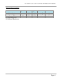
1
EX-9686U-L/XX-L/xx-LO Series
Hardware User Manual
EX-9686U-L/XX-L/xx-LO Series Hardware User Manual
Release Notes
Version
Release Date
Notes
1.20
1.30
2.00
October 1st , 2013
October 30th , 2013
March, 2014
The 2nd release to customer
Add more interfaces info
Add more interfaces info
Disclaimer
This documentation is provided for use with TOPSCCC Technology CO., LTD. products. No
license to TOPSCCC Technology CO., LTD property rights is granted. TOPSCCC
Technology CO., LTD assumes no liability and provides no warranty either expressed or
implied relating ot the usage or intellectual property right infringement that may result from
its use.
TOPSCCC Technology CO., LTD provides this document “as is,” without warranty of any
kind, expressed or implied, including, but not limited to, its particular purpose. TOPSCCC
Technology CO., LTD may make changes to this document without notice.
Page 2
EX-9686U-L/XX-L/xx-LO Series Hardware User Manual
Table of Contents
TABLE OF CONTENTS........................................................................................... 3
1
PRECAUTIONS ............................................................................................... 5
1.1
1.2
1.3
2
PRODUCT FEATURES..................................................................................... 7
2.1
2.2
2.3
3
Overview.......................................................................................................7
Features and Specifications ............................................................................8
Block Diagram ............................................................................................. 10
INTERFACE SPEC - I (EX-9686U-L/XX-L/XX-LO).............................................. 11
3.1
3.2
3.3
4
Safety Precautions.........................................................................................5
Write Prohibited Regions ................................................................................6
Warranty .......................................................................................................6
HDMI Connector.......................................................................................... 13
MicroSD Connector...................................................................................... 14
UART Connectors & Debug Port ................................................................... 15
3.3.1
UART1 Console/Debug Port...................................................................................................................................17
3.3.2
UART2 RS232 Port.....................................................................................................................................................19
3.3.3
UART3 RS485 Port.....................................................................................................................................................20
3.4
3.5
3.6
3.7
3.8
3.9
3.10
USB Connectors .......................................................................................... 21
Audio Interface ............................................................................................ 23
Ethernet Interface ........................................................................................ 24
Power Supply (DC-IN connector)................................................................... 25
GPIO Pin Header......................................................................................... 26
I2C Interface ................................................................................................ 28
CAN Bus Interface ..................................................................................... 30
3.11
3.12
3.13
3.14
BM Connector (Firmware Update)................................................................ 31
EEPROM .................................................................................................. 32
RTC (Real Time Clock)............................................................................... 33
WDT (Watchdog Timer) .............................................................................. 34
INTERFACE SPEC - II (EX-9686U-L/XX-L/XX-LO ONLY) ................................... 35
4.1
4.2
4.3
Parallel Display Interface .............................................................................. 37
LVDS Display Interface................................................................................. 39
Touch Screen Interface................................................................................. 41
Page 3
EX-9686U-L/XX-L/xx-LO Series Hardware User Manual
4.4
4.5
4.6
4.7
4.8
4.9
4.10
5
Power Output Connector .............................................................................. 42
Camera Sensor Interface.............................................................................. 43
MIPI Interface .............................................................................................. 44
Expansion Connector ................................................................................... 45
Keypad Connector ....................................................................................... 46
Mini-PCIe Connector .................................................................................... 47
SATA Interface ........................................................................................... 48
EX-9686U-L (MAIN BOARD) PCB OUTLINE DRAWING .................................... 49
6 ELECTRICAL SPECIFICATIONS.........................................................................51
APPENDIX A: BOX HEADER TO DB9 CABLE ........................................................ 52
APPENDIX B: 7-INCH LCD BRIEF (WVGA) ............................................................53
APPENDIX C: 7-INCH LCD BRIEF (WSVGA).......................................................... 55
APPENDIX D: 10.1-INCH LCD BRIEF ....................................................................57
APPENDIX E: 15-INCH LCD BRIEF ....................................................................... 58
APPENDIX F: 15-INCH LCD BRIEF (HIGH BRIGHTNESS)....................................... 60
APPENDIX G: 21.5-INCH LCD BRIEF ....................................................................62
Page 4
EX-9686U-L/XX-L/xx-LO Series Hardware User Manual
1 Precautions
1.1
Safety Precautions
In order to use this product safely, please take special note of the following precautions.
• Read all product manuals and related documentation before using this product. Use
this product correctly and safely. Follow all warnings.
• If operating or extending this product in a manner not described in this manual,
please do so at your own risk. Be sure to fully read this manual and other technical
information on our website and proceed safely and responsibly.
• Do not install this product in a place with a lot of water, moisture, dust or soot. This
could cause product failure, fire, or an electric shock.
• Some parts of this product generate heat and can reach high temperatures. This
may cause burns if it is improperly handled. Do not touch the electronic components
or surrounding area while powered on or immediately after being turned off.
• Carry out any design and development only after you have thoroughly read and
understood this manual and any other related technical materials on the website or
in the data sheets. Test your product thoroughly for reliability and safety.
• This product is not intended for applications that require extremely high reliability,
safety, functionality and accuracy: including but not limited to medical equipment,
traffic control systems, combustion control systems, and safety equipment. This
company is not liable for death or injury if used in such systems.
• This product uses semiconductor components designed for generic electronics
equipment such as office automation, communications, measurement equipment
and machine tools. Foreign noise or a power surge may cause this product to
malfunction or fail.
• To ensure there is no risk of bodily harm or property damage, be sure to take all
electrical safety precautions such as protection circuits, limit switches, fuse breakers,
or redundant systems. Only use the device after sufficient reliability and safety
measures are in place.
Page 5
EX-9686U-L/XX-L/xx-LO Series Hardware User Manual
1.2
Write Prohibited Regions
Data stored by the EEPROM, i.MX6Q/D electrical fuse (e-Fuse) is used by the software
contained in this product. Do not write to these regions as this may cause the product
stop working correctly. Purposely writing to these regions voids the product warranty.
1.3
Warranty
As described in the Product Warranty Policy provided with this product, the main board is
covered by a one year replacement warranty starting from the time of purchase. Please
note that the other included goods and software are not covered under this warranty. Some
knowledge used by TOPSCCC Technology CO. LTD is provided by third parties, and
TOPSCCC Technology CO. LTD makes no representation or warranty as to the accuracy of
such information.
Page 6
EX-9686U-L/XX-L/xx-LO Series Hardware User Manual
2 Product Features
2.1
Overview
The EX-9686U-L/XX-L/xx-LO is a series of Freescale iMX6 ARM Cortex-A9 based
embedded computer products with a rich set of features. It is a flexible, high performance
and inexpensive computer platform designed for multimedia applications such as digital
signage, in-vehicle infotainment, KIOSK or HMI.
Each device can be installed in advance with Windows Embedded Compact 7, Ubuntu
11.10 or Android 4.2 for immediate evaluation.
Page 7
EX-9686U-L/XX-L/xx-LO Series Hardware User Manual
2.2
Features and Specifications
Features
¾ High performance Cortex A9 processor (quad/dual/single core)
¾ Dedicated hardware MPEG2/4/H.264 1920x1080 Full HD decoder
¾ Dedicated hardware H.264 1920x1080 Full HD encoder
¾ Hardware 2D/3D graphics accelerator
¾ Preinstalled Windows Embedded Compact 7, Ubuntu 11.10 or Android 4.2 OS
¾ Rich set of peripherals (LCD, USB, HDMI, …etc)
EX-9686U-L/XX-LO/XX-L Series Specifications
z Freescale iMX6 ARM Cortex™-A9 core @ 1 GHz, 32 KB L1 cache, 512 KB L2 cache
z 1GB DDR3 SDRAM (Single Core with 512MB DDR3 only)
z 4GB eMMC Flash
z Hardware Video Decoder
H.264 HP profile (up to 50 Mbps)
MPEG 1/2 MP profile (up to 50 Mbps)
MPEG 4 SP/ASP profile (up to 40 Mbps)
„
VC1 SP/MP/AP profile (up to 45 Mbps)
z Hardware Video Encoder
„
MPEG 4 Simple profile 720P 30fps (up to 12 Mbps)
„
H.264 BP/CBP profile 1080P 30fps (up to 14 Mbps)
z 10/100/1000 Mbps Gigabit Ethernet interface RJ-45 connector x1
z Single parallel 24-bit display port, up to 225 Mpixels/sec
z LVDS serial ports - Single port up to 165 Mpixels/sec or dual ports up to 85 MP/sec
z 7”, or 10.1” LCD panel with touch screen x1
z HDMI 1.4 transmitter connector x1
z +12V DC power input connector x1
z USB 2.0 host connector x2
z USB 2.0 OTG connector x1
z Micro SD card socket x1
z SATA x1
z SGTL5000 Audio Codec , Amplifier circuit
z MIC-in connector x1, Earphone connector x1
z Speaker connector x2 (L/R)
z RS485 connector x1
z RS232 connector x2 (one for debug port)
Page 8
EX-9686U-L/XX-L/xx-LO Series Hardware User Manual
z
z
z
z
z
z
GPIO pin header x1 (8 bits for Standard; 16 bits for Optional)
CAN bus phoenix connector x 1 (Optional)
IEEE 802.11 b/g/n Wi-Fi x 1 (Optional)
mini PCI-E for 3G module x 1 (Optional)
MIPI interface x 1 (Optional)
Board Dimension: 101mm x146mm
Page 9
EX-9686U-L/XX-L/xx-LO Series Hardware User Manual
2.3
Block Diagram
SATA
GPIO
LVDS
CAN
PHY
CAN
Bus
PCF8574
MIPI
DDR3 (1GB)
CCIR656
Flash (4GB)
EEPROM
RS232
transceiver
RS232
RS485
transceiver
RS485
HDMI
LCD
RTP
MIC
MicroSD
Headphones
Audio
Codec
USB OTG
Line IN
Amp
iMX6
CPU
Speaker
-L&R
Amp
USB x 2
USB
HUB
RS232
transceiver
USB (WiFi)
Debug
(RS232)
Boot Mode
I2C
USB
(header)
mPCI-e
Keypad
LAN
GbE PHY
1.5V
:
:
5V
DC DC
Over
Voltage
Protection
DC-IN
EXP-1
Power Out
: Connectors or Pin-Headers
: Function blocks
Page 10
EX-9686U-L/XX-L/xx-LO Series Hardware User Manual
3 Interface Spec - I (EX-9686U-L/XX-L/xx-LO)
The following photos and diagrams show connector positions on the EX-9686U-L/XX-L
series of products respectively. The functional details of the connectors are described in
subsequent sections.
Major connectors of EX-9686U-L (Main Board) PCB:
EX-9686U-L (Main Board) PCB Top View
Page 11
EX-9686U-L/XX-L/xx-LO Series Hardware User Manual
EX-9686U-L (Main Board) PCB Bottom View
Connector positions of EX-9686Uxx-LO series:
Page 12
EX-9686U-L/XX-L/xx-LO Series Hardware User Manual
3.1
HDMI Connector
The HDMI receptacle connector supports a standard HDMI interface. Its features include:
z
z
z
z
z
HDMI 1.4a, HDCP 1.4, DVI 1.0 compliant
Hot plug/unplug detection and link status monitor supported
Video resolutions supported:
„
Up to 1080p@120Hz HDTV display
„
QXGA graphics display
„
HDMI 1.4a 4K x 2K video formats
„
HDMI 1.4a 3D video modes with up to 340MHz TMDS clock
Supported color formats:
„
24/30/36/48-bit RGB 4:4:4
„
24/30/36/48-bit YCbCr 4:4:4
„
16/20/24-bit YCbCr 4:2:2
All audio formats as specified by the HDMI Specification Version 1.4a are supported
HDMI pin out
Pin
1
2
3
4
5
6
7
8
9
10
Signal
TMDS Data2+
TMDS Data2 Shield
TMDS Data2−
TMDS Data1+
TMDS Data1 Shield
TMDS Data1−
TMDS Data0+
TMDS Data0 Shield
TMDS Data0−
TMDS Clock+
Pin
11
12
13
14
15
16
17
18
19
Signal
TMDS Clock Shield
TMDS Clock−
CEC
NC
SCL
SDA
Ground
+5V
Hot plug detect
Page 13
EX-9686U-L/XX-L/xx-LO Series Hardware User Manual
3.2
MicroSD Connector
The microSD host connector has the following specification:
z
z
z
SD Host Controller Standard Specification version 3.0
MMC System Specification version 4.2/4.3/4.4
SD Memory Card Specification version 3.0 and supports the Extended Capacity SD
Memory Card
z
SDIO Card Specification version 3.0
microSD Connector Pin-out
Pin
1
2
3
4
5
Signal
Data 2
Data 3
CMD
VDD
CLK
Pin
6
7
8
9
Signal
GND
Data 0
Data 1
CD
Page 14
EX-9686U-L/XX-L/xx-LO Series Hardware User Manual
3.3
UART Connectors & Debug Port
There are 3 UART ports on this device. The connector type and functions are listed in
below table:
UART
Number
Baud
Rate
Connector
Type
Console/Debug port
2x4 box
header
Available
Signals
RS232 signal level
(TX, RX, RTS, CTS)
RS232 signal level
(TX, RX, RTS, CTS)
UART1
115.2K
2x4 box
header
UART2
1Mbps
(max)
UART3
1Mbps
(max)
Notes
2x4 box
header
RS485 signal level
(485+, 485-)
RS485 port
Note: RS485 port works only in
HALF Duplex mode
RS232 port
The console port baud rate is fixed at 115.2Kbps for standard terminal operation.
Both RS232 and RS485 ports support up to 1Mbps baud rate. (** Note: 1Mbps baud rate
is supported in certain models of EX9686U-L hardware, contact us for details if you
plan to use 1Mbps baud rate **)
RS-232
(UART2)
RS-485
(UART3)
Console
(UART1)
Page 15
EX-9686U-L/XX-L/xx-LO Series Hardware User Manual
One 2x4 box header to DB9 cable is included. See Appendix A for the detailed info on the
cable pin assignment.
2x4 Box Header:
7
1
8
2
DB9
Pin
1
2
3
4
5
6
7
8
9
2x4
header
-4
6
1
5
7
8
2
--
RS232
RS485
--RxD
TxD
--GND
--RTS
CTS
---
--485+
485--GND
---------
DB9 Male Connector
DB9 Female Connector
1 2 3 4 5
5 4 3 2 1
6 7 8 9
9 8 7 6
Page 16
EX-9686U-L/XX-L/xx-LO Series Hardware User Manual
3.3.1
UART1 Console/Debug Port
UART1 Connection Diagram:
UART1 is dedicated as the debug/console port. UART1 default settings are Baud Rate
115200, 8 data bits, no parity, 1 stop bit and no flow control.
A DB9 null modem cable (or adapter) is required when you want to connect UART1 to a
PC with terminal emulation software such as TeraTerm.
UART1 Box Header (CN3 on PCB) Pin Assignment:
UART1 Schematic diagram:
Page 17
EX-9686U-L/XX-L/xx-LO Series Hardware User Manual
Page 18
EX-9686U-L/XX-L/xx-LO Series Hardware User Manual
3.3.2
UART2 RS232 Port
UART2 Block Diagram:
iMX6
TX, RX
CPU
RTS, CTS
RS232
2x4
Transceiver
Box Header
UART2 (with TX, RX, RTS, CTS signals) works as a regular RS232 port.
UART2 Box Header (CN2 on PCB) Pin Assignment:
Page 19
EX-9686U-L/XX-L/xx-LO Series Hardware User Manual
3.3.3
UART3 RS485 Port
UART3 Block Diagram:
iMX6
CPU
2x4
ZT485E
Box Header
ZT485E: RS485 transceiver. RS485 works in half duplex mode.
UART3 Box Header (CN1 on PCB) Pin Assignment:
7
5
3
1
4 : 485+
8
6
4
2
6 : 485-
Page 20
EX-9686U-L/XX-L/xx-LO Series Hardware User Manual
3.4
USB Connectors
The USB interfaces on EX-9686U-L/XX-L/xx-LO include a USB 2.0 OTG port and two
USB2.0 host ports. Speed of up to 480 Mbps supported.
The USB 2.0 host interface is connected to a hub controller to extend host ports. Two of the
USB2.0 hub ports are available for users. The other two USB ports are reserved for
802.11b/g/n WiFi module and 3G (WCDMA) module.
USB Port:
USB2.0 OTG Connector
USB2.0 OTG
iMX6
CPU
USB2.0 Host
USB2.0 Connectors
(type-A)
4-port
USB2.0 (header for WiFi)
Hub
USB2.0 (PCI-e for 3G)
NOTE: The USB 2.0 OTG can be used in host mode or device mode. If you would like to
use it in host mode, a separate OTG-to-host cable is required.
The USB 2.0 host connector is a regular USB type A connector that can be connected to
+5V USB storage device. This port is mainly used to connect to USB flash drive.
Pin
1
2
3
4
Signal
5V
Data Data +
GND
Pin
1
2
3
4
5
Signal
5V
Data Data +
ID
GND
Page 21
EX-9686U-L/XX-L/xx-LO Series Hardware User Manual
USB port 2 is connected to J13 pin header and to PCI-e connector for 3G module.
USB port 3 is connected to J14 pin header for 802.11b/g/n module.
J13 pin1
J14 pin1
Page 22
EX-9686U-L/XX-L/xx-LO Series Hardware User Manual
3.5
Audio Interface
The audio interface is implemented by a SGTL5000 audio codec. The data and control
interface between CPU and SGTL5000 is I2S.
The available audio connectors are MIC-in, Headphone-out, speaker Left and speaker
Right. The Line-in interface is connected to pin header JP1.
MIC-IN
Head-Phone
Speaker L/R
JP1 pin 1
Audio Interfaces:
Amplifier
iMX6
CPU
I2S
Audio
Codec
Speaker
Head Phone (out)
MIC (in)
Line-in header
Page 23
EX-9686U-L/XX-L/xx-LO Series Hardware User Manual
3.6
Ethernet Interface
The 10/100/1000 Mbps Gigabit Ethernet interface is available with a standard RJ-45
connector.
Ethernet:
iMX6
CPU
Ethernet
PHY
RJ-45
Connector
The EX-9686U-L/XX-L/xx-LO unit is configured with a unique MAC address in the OS.
Page 24
EX-9686U-L/XX-L/xx-LO Series Hardware User Manual
3.7
Power Supply (DC-IN connector)
The standard DC power adapter included in the EX-9686U-L/XX-L/xx-LO unit is +12V at
1.5A or higher. Power input should be applied to the DC-IN connector.
Page 25
EX-9686U-L/XX-L/xx-LO Series Hardware User Manual
3.8
GPIO Pin Header
The GPIO pin header provides user to connect up to 16 GPIO devices (+3.3V signal level).
The GPIO controller could be either a PCF8574 chip (with 100Khz I2C interface) or a
PCA8574 chip (with 400Khz I2C interface).
J16 pin 2
J16 pin 1
Page 26
EX-9686U-L/XX-L/xx-LO Series Hardware User Manual
Ex-9686U-L (Main Board) GPIO Connector:
J16 pin 1
EX-9686Uxx-L GPIO Connector:
J16 pin 1
J16 pin 20
GPIO pin assignment:
J16 pin #
Port-pin
GPIO #
1
1-P0
232
3
1-P1
233
5
1-P2
234
7
1-P3
235
9
1-P4
236
11
1-P5
237
13
1-P6
238
15
1-P7
239
17
GND
---
19
5V
---
J16 pin #
Port-pin
GPIO #
2
0-P0
224
4
0-P1
225
6
0-P2
226
8
0-P3
227
10
0-P4
228
12
0-P5
229
14
0-P6
230
16
0-P7
231
18
GND
---
20
3.3V
---
Note: 8-bit GPIO (1-P0 to 1-P7) is available on board. 0-P0 to 0-P7 GPIO is optional.
For more information about programming GPIO, please refer to a separate document:
“Application Note GPIO”.
Page 27
EX-9686U-L/XX-L/xx-LO Series Hardware User Manual
I2C Interface
3.9
The I2C works as a master port by default: The master port is pulled high to +3.3V with 2
resistors internally. The slave devices have to be connected directly without additional
power supply on I2C bus.
The J1 I2C interface is connected to iMX6 I2C channel 3 and shared the same bus with
GPIO controller and J20 EXP-1 bus.
The I2C speed can be up to 400Khz (fast mode) in some models of Ex-9686U-L (Main
(** Please contact us for details if you plan to use 400Khz I2C **)
Board)
(
I2C Master Port
9686 L/XX
LO
3.3V
R R
iMX6
CPU
J20
I2C
ch3
PCF8574
or
PCA8754
1
SDA
SCL
3
EXP-1
J16
GPIO
I2C Slave Device
J1
I2C Bus
GND
SDA
SCL
Page 28
EX-9686U-L/XX-L/xx-LO Series Hardware User Manual
J1 pin 1
Page 29
EX-9686U-L/XX-L/xx-LO Series Hardware User Manual
3.10
CAN Bus Interface
The Flexible Controller Area Network (FLEXCAN) module is a communication controller
implementing the CAN protocol according to the CAN 2.0B protocol specification
z
z
z
Version 2.0 B
„
Standard data and remote frames
„
Extended data and remote frames
„
Zero to eight bytes data length
„
Programmable bit rate up to 1 Mb/sec
„
Content-related addressing
Flexible mailboxes of eight bytes data length
Listen only mode capability
CAN Connector out line
CAN bus schematic
Page 30
EX-9686U-L/XX-L/xx-LO Series Hardware User Manual
3.11
BM Connector (Firmware Update)
The J8 connector is used to select the mode of EX-9686U-L/XX-L/xx-LO: Normal Operation
mode or Firmware Download mode.
For more information about Firmware Download mode (to burn firmware image), please
refer to “Firmware Download” application note or “Quick Start Guide” document.
J8 pin 1
Firmware Download:
Pin 1, 2 open
Pin 3, 4 short
J8 pin 1
Normal Operation:
Pin 1, 2 short
Pin 3, 4 short
Page 31
EX-9686U-L/XX-L/xx-LO Series Hardware User Manual
3.12
EEPROM
A 4Kx8bit (32K-bit) non-volatile eeprom is mounted on board to keep system data.
Part of the storage is available for user to store application data.
The eeprom data read/write is done by iMX6 I2C channel-1.
A device driver in Android and Linux is available for application software to read/write
eeprom data.
Page 32
EX-9686U-L/XX-L/xx-LO Series Hardware User Manual
3.13
RTC (Real Time Clock)
The RTC is implemented by a DS1307 real time clock chip connected to iMX6 I2C
channel-1. A rechargeable coin battery (3V/5mAh) is mounted on board to keep RTC in
normal operation when system power is off.
Page 33
EX-9686U-L/XX-L/xx-LO Series Hardware User Manual
3.14
WDT (Watchdog Timer)
The WDT function is implemented by utilizing iMX6 internal Watchdog Timer (WDOG).
The Watchdog Timer (WDOG) protects against system failures by providing a method by
which to escape from unexpected events or programming errors.
Once the WDOG is activated, it must be serviced by the software on a periodic basis. If
servicing does not take place, the timer times out. Upon timeout, the WDOG asserts the
internal system reset signal to the iMX6 System Reset Controller.
For information on how to set up WDT in Android or Linux, please refer to the “Watchdog
timer application note”.
For more information about iMX6 WDOG, please refer to iMX6 Q/D Reference Manual.
Page 34
EX-9686U-L/XX-L/xx-LO Series Hardware User Manual
4 Interface Spec - II (EX-9686U-L/XX-L/xx-LO Only)
The interfaces in this chapter are specifically for the EX-9686U-L/XX-L/xx-LO products.
J6
PWR_GPIO
JC1
CSI
J9
MIPI
JC2
CSI
JP1
Line
In
J8
BM
JP2
BL
PWR
J7
Power Out
J10
LVDS
J11
PCI-e/USB2
SW2
CABC
J12
Touch
Pad
J13
USB2
CN4
SATA
CN6
RTP
SW1
Keypad
J20
EXP-1
JP3
BL PWR
J21
BT
CFG
CN5
TTL
LCD
USB1
USB4
J14
USB3
Page 35
EX-9686U-L/XX-L/xx-LO Series Hardware User Manual
Connector
Number
CN5
40pin FPC for parallel display interface
JP3
TTL LCD backlight power
J10
LVDS display (dual LVDS channel)
JP2
LVDS LCD backlight power
SW2
Reserved for CABC backlight
CN6
4-wrie resistive touch screen interface
J12
Capacitive touch screen interface
J7
Power Output
JC1, JC2
Camera Sensor Interface (CSI)
J9
MIPI CSI/DSI interface
J20
EXP-1 (expansion connector)
SW1
Keypad
J11
PCI-e form factor with USB2
J13 / J14
USB2 / USB3 pin headers
CN4
SATA Interface
JP1
Audio Line-in pin header
J8
J21
BM (Mode Selection: burn firmware or
normal operation)
BT CFG (reserved)
J6
Power & GPIO (reserved)
Part Description
Notes
Parallel display interfaces
LVDS display interfaces
Touch screen interfaces
Power output
Expansion connector
Refer to Chapter 3 for USB.
Refer to Chapter 3 for Audio
Refer to Chapter 3 for BM
Page 36
EX-9686U-L/XX-L/xx-LO Series Hardware User Manual
4.1
Parallel Display Interface
The parallel display interface (CN5) is designed to use with a 7” 800x480 TFT LCD. Other
size and resolution of LCDs can also be used with this interface with proper signal
connection.
The JP3 backlight connector is reserved for the need to supply a backlight or LCD reset
signal to LCD. The schematic of CN5 and JP3 are in below diagram.
Page 37
EX-9686U-L/XX-L/xx-LO Series Hardware User Manual
Most of the interface pins are connected directly to iMX6 processor pins. For the electrical
DC/AC parameters of the pins, please refer to Freescale iMX6 processor data sheet.
JP3 Pin 1
CN5Pin 1
Page 38
EX-9686U-L/XX-L/xx-LO Series Hardware User Manual
4.2
LVDS Display Interface
There are 2 LVDS channels output on J10 connector. These outputs are used to
communicate RGB data and controls to external LCD displays.
The LVDS channels may be used as follows:
z Single channel output
z Two channels outputs for two displays
z Split channel output to a single display
The JP2 pin header is to select a +5V or +12V backlight power to LCD display module.
Warning: Please set JP2 at correct voltage supply. Incorrect setting will
burn down LCD backlight.
Page 39
EX-9686U-L/XX-L/xx-LO Series Hardware User Manual
SW2 is reserved for CABC backlight control.
J10 pin1
JP2 pin1
J10 pin2
SW2 pin1
Page 40
EX-9686U-L/XX-L/xx-LO Series Hardware User Manual
4.3
Touch Screen Interface
CN6 is for connecting to a 4-wire resistive touch screen. The pin assignment can be
configured by mounting different resistors as in below schematic.
J12 can be used as capacitive touch screen or touch pad interface. In addition to the +5V
and +3.3V power pins, two GPIOs for interrupt/reset and one I2C (channel 2 on iMX6Q/D)
master port are on the connector. The interrupt pin (KEY_INT) is connected to iMX6Q/D
ball number F19 (ball name SD2_CMD) and reset pin (KEY_RESET) is connected to
iMX6Q/D ball number C21 (ball name SD2_CLK).
CN6 Pin 1
J12 pin1
Page 41
EX-9686U-L/XX-L/xx-LO Series Hardware User Manual
4.4
Power Output Connector
The J7 connector provides +3.3V, +5V, +12V power supply to external devices.
J7 pin1
Page 42
EX-9686U-L/XX-L/xx-LO Series Hardware User Manual
4.5
Camera Sensor Interface
JC1 and JC2 connectors are for parallel camera port. The schematic is as below:
JC1 pin1
JC2 pin1
Page 43
EX-9686U-L/XX-L/xx-LO Series Hardware User Manual
4.6
MIPI Interface
There are 2x MIPI interfaces (DSI and CSI-2) in a single high density connector (J9):
z MIPI/DSI: two lanes at 1 Gbps pixel rate.
z
MIPI/CSI-2 serial camera port: supporting up to 1000 Mbps/lane in 1/2/3-lane mode
and up to 800 Mbps/lane in 4-lane mode. The CSI-2 Receiver core can manage one
clock lane and up to four data lanes.
J9 pin1
Page 44
EX-9686U-L/XX-L/xx-LO Series Hardware User Manual
4.7
Expansion Connector
J20 connector is reserved for future expansion:
J20 Pin 1
Page 45
EX-9686U-L/XX-L/xx-LO Series Hardware User Manual
4.8
Keypad Connector
SW1 connector can be used in Android (or other OS) as keypad input.
SW1 pin 1
Page 46
EX-9686U-L/XX-L/xx-LO Series Hardware User Manual
4.9
Mini-PCIe Connector
The Mini-PCIe connector J11 now supports only 3G (WCDMA) module.
Page 47
EX-9686U-L/XX-L/xx-LO Series Hardware User Manual
4.10
SATA Interface
The CN4 connector is an integrated Serial Advanced Technology Attachment (SATA)
controller that is compatible with the Advanced Host Controller Interface (AHCI)
specification.
z
z
Compliant with the following specifications:
„
Serial ATA 2.0
„
AHCI Revision 1.3
SATA 1.5 Gb/s and SATA 3.0 Gb/s speed
Pin
1
2
3
4
Signal
GND
Data A+
Data AGND
Pin
5
6
7
Signal
Data BData B+
GND
Page 48
EX-9686U-L/XX-L/xx-LO Series Hardware User Manual
5 EX-9686U-L (Main Board) PCB Outline Drawing
Page 49
EX-9686U-L/XX-L/xx-LO Series Hardware User Manual
Page 50
EX-9686U-L/XX-L/xx-LO Series Hardware User Manual
6 Electrical Specifications
Absolute Maximum Ratings
Min
Max
Unit
8.55
37.8
V
VI (PCF8574 GPIO)
input voltage
VSS-0.5
VDD+0.5
V
(*1)
II (PCF8574 GPIO)
DC Input current
--
±20
mA
(*1)
IO (PCF8574 GPIO)
DC output current
--
±25
mA
(*1)
Min
Max
Unit
Note
9
36
V
VIL (PCF8574 GPIO)
Input low
-0.5
+0.3VDD
V
(*1)
VIH (PCF8574 GPIO)
Input high
0.7VDD
VDD+0.5
V
(*1)
Main Power Supply (DC-IN)
Note
Operating Range:
Main Power Supply (DC-IN)
VSS = 0V. VDD = +3.3V
Note (*1): For more details, please refer to PCF8574 data sheet.
Page 51
EX-9686U-L/XX-L/xx-LO Series Hardware User Manual
Appendix A: Box Header to DB9 Cable
Page 52
EX-9686U-L/XX-L/xx-LO Series Hardware User Manual
Appendix B: 7-inch LCD Brief (WVGA)
General Features:
The 7-inch LCD panel is a transmissive type color active matrix TFT (Thin Film Transistor)
liquid crystal display (LCD) that uses amorphous silicon TFT as a switching device. This
model is composed of a TFT-LCD module, a driver circuit, touch panel, and a backlight unit.
Graphics and texts can be displayed on a WVGA 800 (W) x 3 x 480 (H) dots (16:9 aspect
ratio) with 262,144 colors by supplying 18 bits data signal (6 bits for each color).
LCD Module Features
z
z
z
z
z
Transmissive and back-light with 24 LEDs available
TN (Twisted Nematic) mode
Digital RGB (6bits/color) data transfer
Data enable mode
Back-light dimming control
LCD Module Specifications
Item
Screen Size
Display Resolution
Active Area
Outline Dimension
Display Mode
Surface Treatment
Pixel Arrangement
Pixel Size
Display Color
Input Interface
Specification
Unit
7.0 inches
800 (H) x 480 (V)
154.08 (H) x 85.92 (V)
165.00 (H) x 104.00 (V) x 6.55 (T)
Normally white mode
Anti-glare(AG)
RGB Vertical Stripe
190.5 x 190.5
262K
Digital RGB (6bits/color) Data Transfer
Diagonal
Pixel
mm
mm
---um
---
Mechanical Data
Page 53
EX-9686U-L/XX-L/xx-LO Series Hardware User Manual
Item
Horizontal (H)
Vertical (V)
Thickness (T)
Weight
Note (1) Not Include Component
Module Size
Value
Unit
Notes
165.00
104.00
6.55
TBD
mm
mm
mm
g
(1)
--
Environmental Rating
Item
Symbol
Min
Max
Storage Temperature
Operating Temperature
TSTG
TOPR
-30
-20
80
70
Unit
o
o
C
C
Optical Characteristics
Item
Symbol
Value
Unit
Brightness
Contrast Ratio
B
CR
300
250
cd/m2
--
Page 54
EX-9686U-L/XX-L/xx-LO Series Hardware User Manual
Appendix C: 7-inch LCD Brief (WSVGA)
General Features:
The 7-inch LCD panel is a transmissive type color active matrix TFT (Thin Film Transistor)
liquid crystal display (LCD) that uses amorphous silicon TFT as a switching device. This
model is composed of a TFT-LCD module, a driver circuit, touch panel and backlight unit.
Graphics and texts can be displayed on a XGA 1024 (W) x RGB x 600 (H) dots with 16.7M
colors by supplying 24 bits data signal (8 bits for each color).
LCD Module Features:
z
z
z
Transmissive and back-light with 18 LEDs available
Digital RGB (8 bits / color) data transfer
ROHS Compliant
LCD Module Specifications
Item
Screen Size
Display Resolution
Active Area
Outline Dimension
Display Mode
Surface Treatment
Pixel Arrangement
Pixel Size
Display Color
Input Interface
Specification
Unit
7.0 inches
1024 (H) x 600 (V)
153.6 (H) x 90.0 (V)
165.75 (H) x 105.39 (V) x 3.40 (T)
Normally white mode
Anti-glare (AG)
RGB Vertical Stripe
0.150 x 0.150
16.7M
Digital RGB (8 bits/color) Data Transfer
Diagonal
Pixel
mm
mm
---mm
---
Page 55
EX-9686U-L/XX-L/xx-LO Series Hardware User Manual
Mechanical Data
Item
Horizontal (H)
Vertical (V)
Module Size
Thickness (T)
Weight
Note (1) Not Include Component
Value
Unit
Notes
165.75
105.39
3.40
TBD
mm
mm
mm
g
(1)
--
Environment Rating
Item
Symbol
Min
Max
Storage Temperature
Operating Temperature
TSTG
TOPR
-30
-20
70
60
Unit
o
o
C
C
Optical Characteristics
Item
Symbol
Min
Typical
Unit
Brightness
Contrast Ratio
B
CR
350
400
400
500
cd/m2
--
Page 56
EX-9686U-L/XX-L/xx-LO Series Hardware User Manual
Appendix D: 10.1-inch LCD Brief
General Features:
The 10.1-inch LCD panel is a transmissive type color active matrix TFT (Thin Film
Transistor) liquid crystal display (LCD). This model is composed of a TFT-LCD module, a
driver circuit, touch panel and a back-light unit. The resolution of a 10.1” contains 1280 (W)
x RGB x 800 (H) dots and can display up to 16.7M colors.
LCD Module Features:
z Transmissive and back-light with LEDs available
z One channel LVDS interface
z ROHS Compliant
LCD Module Specifications:
Item
Screen Size
Display Resolution
Active Area
Outline Dimension
Display Mode
Pixel Arrangement
Pixel Size
Display Color
Surface Treatment
Input Interface
Environmental Rating
Item
Storage Temperature
Operating Temperature
Specification
Unit
10.1 inches
1280 x RGB x 800
216.96 (H) x 135.6 (V)
227.7 (H) x 147.8 (V) x 4.6 (D)
Normally white mode
RGB Stripe
0.1695 x 0.1695
16.7M
Anti-Glare
LVDS Interface
Diagonal
Pixel
mm
mm
--mm
--
Symbol
Min
Max
TSTG
TOPR
-20
0
60
50
Optical Characteristics
Item
Symbol
Brightness
Contrast Ratio
-CR
--
Unit
o
o
C
C
Min
Typical
Unit
280
800
350
cd/m2
--
--
Page 57
EX-9686U-L/XX-L/xx-LO Series Hardware User Manual
Appendix E: 15-inch LCD Brief
General Features:
The 15-inch LCD panel is a transmissive type color active matrix TFT (Thin Film Transistor)
liquid crystal display (LCD) that uses amorphous silicon TFT as a switching device. This
model is composed of a TFT-LCD module, a driver circuit, touch panel and a back-light unit.
The resolution of a 15” contains 1024 (W) x RGB x 768 (H) dots and can display up to
16.2M colors.
LCD Module Features:
z Transmissive and back-light with LEDs available
z One channel LVDS interface
z ROHS Compliant
LCD Module Specifications:
Item
Screen Size
Display Resolution
Active Area
Outline Dimension
Display Mode
Pixel Arrangement
Pixel Size
Display Color
Surface Treatment
Input Interface
Specification
Unit
15 inches
1024 x RGB x 768
304.128 (H) x 228.096 (V)
326.5 (H) x 253.5.2 (V) x 12.0 (D)
Normally white mode
RGB Vertical Stripe
0.297 x 0.297
16.2M
Anti-Glare
LVDS Interface
Diagonal
Pixel
mm
mm
--mm
---
Mechanical Data
Item
Module Size
Horizontal (H)
Vertical (V)
Thickness (T)
Weight
Typical
Max
Unit
326.50
253.50
12.00
930
---960
mm
mm
mm
g
Environment Rating
Page 58
EX-9686U-L/XX-L/xx-LO Series Hardware User Manual
Item
Symbol
Min
Max
Storage Temperature
Operating Temperature
TSTG
TOPR
-30
-20
80
70
Unit
o
o
C
C
Optical Characteristics
Item
Symbol
Min
Typical
Unit
White Brightness
Contrast Ratio
-CR
-450
350
800
cd/m2
--
Page 59
EX-9686U-L/XX-L/xx-LO Series Hardware User Manual
Appendix F: 15-inch LCD Brief (High Brightness)
General Features:
The 15-inch LCD panel is a transmissive type color active matrix TFT (Thin Film Transistor)
liquid crystal display (LCD) that uses amorphous silicon TFT as a switching device.
This model is composed of a TFT-LCD module, a driver circuit, touch panel and a
back-light unit. The resolution of a 15” contains 1024 (W) x RGB x 768 (H) dots and can
display up to 16.2M colors.
LCD Module Features:
z
z
z
z
Transmissive and back-light with LEDs available
TN (Twisted Nematic) mode
One channel LVDS interface
ROHS Compliant
Page 60
EX-9686U-L/XX-L/xx-LO Series Hardware User Manual
LCD Module Specifications:
Item
Screen Size
Display Resolution
Active Area
Outline Dimension
Display Mode
Pixel Arrangement
Pixel Size
Display Color
Surface Treatment
Input Interface
Specification
Unit
15 inches
1024 x RGB x 768
304.128 (H) x 228.096 (V)
326.5 (H) x 253.5.2 (V) x 14.3 (D)
Normally white mode
RGB Vertical Stripe
0.297 x 0.297
16.2M / 262K
Anti-Glare
LVDS Interface
Diagonal
Pixel
mm
mm
--mm
---
Environmental Rating
Item
Symbol
Min
Max
Unit
Storage Temperature
Operating Temperature
TSTG
TOPR
-30
-30
85
85
Item
Symbol
Min
Typical
Units
White Brightness
Contrast Ratio
-CR
960
400
1200
700
cd/m2
o
o
C
C
Optical Characteristics
--
Page 61
EX-9686U-L/XX-L/xx-LO Series Hardware User Manual
Appendix G: 21.5-inch LCD Brief
General Features:
The 21.5-inch LCD panel is a transmissive type color active matrix TFT (Thin Film
Transistor) liquid crystal display (LCD) that uses amorphous silicon TFT as a switching
device. This model is composed of a TFT-LCD module, a driver circuit, touch panel and a
back-light unit. The resolution of a 21.5” contains 1920 (W) x RGB x 1080 (H) dots and can
display up to 16.7M (RGB 6-bit + Hi_FRC) colors.
LCD Module Features:
z
z
z
z
Transmissive and back-light with LEDs available
TN (Twisted Nematic) mode
Dual channel LVDS interface
ROHS Compliant
LCD Module Specifications:
Item
Screen Size
Display Resolution
Active Area
Outline Dimension
Display Mode
Pixel Arrangement
Pixel Size
Display Color
Surface Treatment
Input Interface
Specification
Unit
21.5 inches
1920 x RGB x 1080
476.64 (H) x 268.11 (V)
-- (H) x -- (V) x -- (D)
Normally white mode
RGB Vertical Stripe
0.248 x 0.248
16.7M (RGB 6-bit + Hi_FRC)
Anti-Glare
LVDS Interface
Diagonal
Pixel
mm
mm
--mm
---
Environmental Rating
Item
Symbol
Min
Max
Storage Temperature
Operating Temperature
TSTG
TOPR
0
-20
50
60
Units
o
o
C
C
Page 62
EX-9686U-L/XX-L/xx-LO Series Hardware User Manual
Optical Characteristics
Item
White Brightness
White Brightness
Contrast Ratio
(1) High Brightness
(2) Standard Brightness
Symbol
Min
Typical
Units
Notes
--CR
1000
300
600
1200
350
1000
cd/m2
cd/m2
(1)
(2)
--
Page 63