1
EMS-XL
Electrophysiology System
USER MANUAL
DDE-965-001
Rev A August 2011
Conformity according to the Council Directive 93/42/EEC concerning Medical Devices
as amended by 2007/47/EC
Manufacturer’s Name
:
Mennen Medical Ltd.
4 Hayarden Street, Yavne, 81228
P.O. Box 102, Rehovot, 76100, Israel
Tel.: +972-8-9323333
Fax: +972-8-9328510
European Representative
:
Charter-Kontron Limited
Unit 18 Avant Business Centre
21 Denbigh Road
Milton Keynes
MK1 1DT England
Tel.: 01908 646070
Fax: 01908 646030
US Representative:
Mennen Medical Corp
950 Industrial Boulevard
Southampton, PA 18966
Phone: 215-259-1020X1026
Fax: 215-675-6212
Toll Free: 800-223-2201
Publication No. DDE-965-001 Ver 1.39
Revision: Rev A August 2011
Copyright © Mennen Medical Mennen Medical Ltd. 2011. All RIGHTS RESERVED
Registered trademarks are the intellectual property of their respective holders.
ii
Mennen Medical
Important Notice
This document is delivered subject to the following conditions and restrictions:
The EMS-XL User’s Guide contains proprietary information of Mennen Medical Ltd.
This information is supplied solely for the purpose of assisting authorized users of
Mennen Medical Ltd. products. The instructions presented in this guide should in no
way supersede established medical protocol concerning patient care.
No part of the contents hereof may be used for any other purposes, disclosed to any
person or firm, or reproduced by any means, without the express prior written
permission of Mennen Medical Ltd.
The text and drawings herein are for the purposes of illustration and reference only. The
specifications on which they are based are subject to change without notice.
Trademarks
EMS-XL is a registered trademark of Mennen Medical Ltd.
Other company and brand, product and service names are for identification purposes
only and may be trademarks or registered trademarks of their respective holders. Data
is subject to change without notice.
Responsibility of Manufacturer
Mennen Medical, Ltd. considers itself responsible for the effects on safety, reliability,
and performance of the equipment only if:
• Repairs are carried out by authorized Mennen Medical personnel only.
• Electrical installation of the room in which the system is installed complies with all
aspects of the relevant internationally recognized electrical safety standards, as well
as specific hospital requirements.
• The equipment is used in accordance with instructions for use.
EMS-XL User’s Guide
iii
iv
Mennen Medical
EMS-XL User’s Guide
Table of Contents
Chapter 1 What You Should Know
Intended Use of the EMS-XL System . . . . . . . . . . . . . . . . . . . . . . . . . . . . . . . . . . 1-1
Using the EMS-XL System . . . . . . . . . . . . . . . . . . . . . . . . . . . . . . . . . . . . . . . . . . 1-1
Replacement of the CPU Battery. . . . . . . . . . . . . . . . . . . . . . . . . . . . . . . . . . . . . . 1-2
Compliance . . . . . . . . . . . . . . . . . . . . . . . . . . . . . . . . . . . . . . . . . . . . . . . . . . . . . . 1-3
Label Locations & Symbol Descriptions. . . . . . . . . . . . . . . . . . . . . . . . . . . . . . . . 1-4
General Use of Accessories . . . . . . . . . . . . . . . . . . . . . . . . . . . . . . . . . . . . . . . . . . 1-5
Environmental Specifications . . . . . . . . . . . . . . . . . . . . . . . . . . . . . . . . . . . . . . . . 1-5
Where to Find Information . . . . . . . . . . . . . . . . . . . . . . . . . . . . . . . . . . . . . . . . . . 1-7
Chapter 2 Warnings and Precautions
Prescription Notice. . . . . . . . . . . . . . . . . . . . . . . . . . . . . . . . . . . . . . . . . . . . . . . . . 2-1
Biocompatibility . . . . . . . . . . . . . . . . . . . . . . . . . . . . . . . . . . . . . . . . . . . . . . . . . . 2-1
Radiation . . . . . . . . . . . . . . . . . . . . . . . . . . . . . . . . . . . . . . . . . . . . . . . . . . . . . . . . 2-1
Transducer Protection . . . . . . . . . . . . . . . . . . . . . . . . . . . . . . . . . . . . . . . . . . . . . . 2-2
SAFETY WARNINGS . . . . . . . . . . . . . . . . . . . . . . . . . . . . . . . . . . . . . . . . . . . . . 2-2
Explosion Hazard . . . . . . . . . . . . . . . . . . . . . . . . . . . . . . . . . . . . . . . . . . . . . . . . . . 2-2
Electrical Shock Hazards . . . . . . . . . . . . . . . . . . . . . . . . . . . . . . . . . . . . . . . . . . . . 2-3
CAUTIONS . . . . . . . . . . . . . . . . . . . . . . . . . . . . . . . . . . . . . . . . . . . . . . . . . . . . . . 2-4
Safety Rating and Manufacturer Identification Label . . . . . . . . . . . . . . . . . . . . . . 2-5
Warning and Compliance Labels . . . . . . . . . . . . . . . . . . . . . . . . . . . . . . . . . . . . . . 2-5
Chapter 3 Introduction
Overview. . . . . . . . . . . . . . . . . . . . . . . . . . . . . . . . . . . . . . . . . . . . . . . . . . . . . . . . . . 3-1
Introduction to Basic System Hardware Components . . . . . . . . . . . . . . . . . . . . . . . 3-2
Amplifiers. . . . . . . . . . . . . . . . . . . . . . . . . . . . . . . . . . . . . . . . . . . . . . . . . . . . . . . . 3-4
Connection Boxes . . . . . . . . . . . . . . . . . . . . . . . . . . . . . . . . . . . . . . . . . . . . . . . . . 3-5
EMS-XL Special Features . . . . . . . . . . . . . . . . . . . . . . . . . . . . . . . . . . . . . . . . . . . . 3-6
Comprehensive Full Disclosure . . . . . . . . . . . . . . . . . . . . . . . . . . . . . . . . . . . . . . . 3-6
Computerized Integrated Stimulator . . . . . . . . . . . . . . . . . . . . . . . . . . . . . . . . . . . 3-6
Continuous Case Log . . . . . . . . . . . . . . . . . . . . . . . . . . . . . . . . . . . . . . . . . . . . . . . 3-6
Reports . . . . . . . . . . . . . . . . . . . . . . . . . . . . . . . . . . . . . . . . . . . . . . . . . . . . . . . . . . 3-6
Additional Features and Functions. . . . . . . . . . . . . . . . . . . . . . . . . . . . . . . . . . . . . 3-6
Offline Utilities . . . . . . . . . . . . . . . . . . . . . . . . . . . . . . . . . . . . . . . . . . . . . . . . . . . 3-7
EMS-XL Review Station - Complementary Product (Optional) . . . . . . . . . . . . . . 3-7
System Specifications . . . . . . . . . . . . . . . . . . . . . . . . . . . . . . . . . . . . . . . . . . . . . . . . 3-7
Chapter 4 Getting Started
Starting the EMS-XL Application . . . . . . . . . . . . . . . . . . . . . . . . . . . . . . . . . . . . . . 4-1
Keyboard Shortcut Keys . . . . . . . . . . . . . . . . . . . . . . . . . . . . . . . . . . . . . . . . . . . . 4-3
. . . . . . . . . . . . . . . . . . . . . . . . . . . . . . . . . . . . . . . . . . . . . . . . . . . . . . . . . . . . . . . . 4-4
Run Time Monitor . . . . . . . . . . . . . . . . . . . . . . . . . . . . . . . . . . . . . . . . . . . . . . . . . . 4-5
Traces Display . . . . . . . . . . . . . . . . . . . . . . . . . . . . . . . . . . . . . . . . . . . . . . . . . . . 4-12
Review Screen . . . . . . . . . . . . . . . . . . . . . . . . . . . . . . . . . . . . . . . . . . . . . . . . . . . . 4-15
Upper Panel Controls . . . . . . . . . . . . . . . . . . . . . . . . . . . . . . . . . . . . . . . . . . . . . . 4-18
Parameter Setup and Command Menus . . . . . . . . . . . . . . . . . . . . . . . . . . . . . . . . 4-24
Left Panel Controls. . . . . . . . . . . . . . . . . . . . . . . . . . . . . . . . . . . . . . . . . . . . . . . . 4-31
ii
Mennen Medical
Printing . . . . . . . . . . . . . . . . . . . . . . . . . . . . . . . . . . . . . . . . . . . . . . . . . . . . . . . . . . 4-34
Exiting the EMS-XL Application. . . . . . . . . . . . . . . . . . . . . . . . . . . . . . . . . . . . . . 4-35
Chapter 5 Setting Up Monitoring
Building a Configuration . . . . . . . . . . . . . . . . . . . . . . . . . . . . . . . . . . . . . . . . . . . . . 5-2
Setting Up Traces Display . . . . . . . . . . . . . . . . . . . . . . . . . . . . . . . . . . . . . . . . . . . 5-2
Channel Select - Run Time Screen . . . . . . . . . . . . . . . . . . . . . . . . . . . . . . . . . . . . 5-7
Channel Select - Review Screen . . . . . . . . . . . . . . . . . . . . . . . . . . . . . . . . . . . . . 5-11
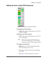
Setting Up Intra-cardiac ECG Channels . . . . . . . . . . . . . . . . . . . . . . . . . . . . . . . 5-13
Channel Settings . . . . . . . . . . . . . . . . . . . . . . . . . . . . . . . . . . . . . . . . . . . . . . . . . 5-14
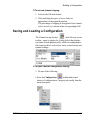
Saving and Loading a Configuration . . . . . . . . . . . . . . . . . . . . . . . . . . . . . . . . . . 5-17
Setting Up Tachycardia Detection . . . . . . . . . . . . . . . . . . . . . . . . . . . . . . . . . . . . . 5-21
Setting Up the Holter Display Mode . . . . . . . . . . . . . . . . . . . . . . . . . . . . . . . . . . . 5-22
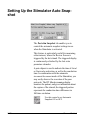
Setting Up the Stimulator Auto Snapshot . . . . . . . . . . . . . . . . . . . . . . . . . . . . . . . 5-26
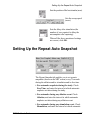
Setting Up the Repeat Auto Snapshot . . . . . . . . . . . . . . . . . . . . . . . . . . . . . . . . . . 5-27
Setting Up Ablation . . . . . . . . . . . . . . . . . . . . . . . . . . . . . . . . . . . . . . . . . . . . . . . . 5-28
Chapter 6 Performing the EP Study
EP Study Overview . . . . . . . . . . . . . . . . . . . . . . . . . . . . . . . . . . . . . . . . . . . . . . . . . 6-1
Registering a Patient. . . . . . . . . . . . . . . . . . . . . . . . . . . . . . . . . . . . . . . . . . . . . . . . . 6-2
Setting Up a Procedure . . . . . . . . . . . . . . . . . . . . . . . . . . . . . . . . . . . . . . . . . . . . . . . 6-6
Loading the System Setup for the Study . . . . . . . . . . . . . . . . . . . . . . . . . . . . . . . . 6-6
Using the Stimulator. . . . . . . . . . . . . . . . . . . . . . . . . . . . . . . . . . . . . . . . . . . . . . . . 6-15
Marking an Event. . . . . . . . . . . . . . . . . . . . . . . . . . . . . . . . . . . . . . . . . . . . . . . . . 6-28
Sinus Node Recovery Time - SNRT . . . . . . . . . . . . . . . . . . . . . . . . . . . . . . . . . . 6-42
Procedure Documentation . . . . . . . . . . . . . . . . . . . . . . . . . . . . . . . . . . . . . . . . . . 6-48
Printing . . . . . . . . . . . . . . . . . . . . . . . . . . . . . . . . . . . . . . . . . . . . . . . . . . . . . . . . . . 6-51
Working with Templates . . . . . . . . . . . . . . . . . . . . . . . . . . . . . . . . . . . . . . . . . . . . 6-56
Ending the EP Study. . . . . . . . . . . . . . . . . . . . . . . . . . . . . . . . . . . . . . . . . . . . . . . . 6-60
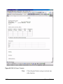
Saving and Storing the EP Study . . . . . . . . . . . . . . . . . . . . . . . . . . . . . . . . . . . . . 6-60
Editing the EMS-XL Report . . . . . . . . . . . . . . . . . . . . . . . . . . . . . . . . . . . . . . . . 6-60
EMS-XL User’s Guide
iii
Ending a Case. . . . . . . . . . . . . . . . . . . . . . . . . . . . . . . . . . . . . . . . . . . . . . . . . . . . 6-64
Saving Part of a Case . . . . . . . . . . . . . . . . . . . . . . . . . . . . . . . . . . . . . . . . . . . . . . 6-64
Chapter 7 Case Playback
Overview. . . . . . . . . . . . . . . . . . . . . . . . . . . . . . . . . . . . . . . . . . . . . . . . . . . . . . . . . . 7-1
Run Time Screen in Playback. . . . . . . . . . . . . . . . . . . . . . . . . . . . . . . . . . . . . . . . . . 7-1
Review Screen in Playback. . . . . . . . . . . . . . . . . . . . . . . . . . . . . . . . . . . . . . . . . . . . 7-2
Chapter 8 Care and Maintenance
General Care and Maintenance. . . . . . . . . . . . . . . . . . . . . . . . . . . . . . . . . . . . . . . . . 8-1
General Cleaning Procedures . . . . . . . . . . . . . . . . . . . . . . . . . . . . . . . . . . . . . . . . . 8-1
Calibration and Preventive Maintenance . . . . . . . . . . . . . . . . . . . . . . . . . . . . . . . . 8-5
Chapter 9 Offline Utilities
Overview. . . . . . . . . . . . . . . . . . . . . . . . . . . . . . . . . . . . . . . . . . . . . . . . . . . . . . . . . . 9-1
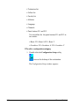
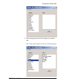
Configuration Setup Utility . . . . . . . . . . . . . . . . . . . . . . . . . . . . . . . . . . . . . . . . . . . 9-1
Archive Utility . . . . . . . . . . . . . . . . . . . . . . . . . . . . . . . . . . . . . . . . . . . . . . . . . . . . . 9-5
Storing Patient Data . . . . . . . . . . . . . . . . . . . . . . . . . . . . . . . . . . . . . . . . . . . . . . . . 9-5
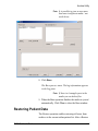
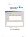
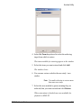
Restoring Patient Data . . . . . . . . . . . . . . . . . . . . . . . . . . . . . . . . . . . . . . . . . . . . . . 9-9
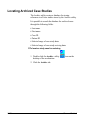
Locating Archived Case Studies . . . . . . . . . . . . . . . . . . . . . . . . . . . . . . . . . . . . . 9-12
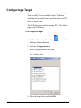
Configuring a Target . . . . . . . . . . . . . . . . . . . . . . . . . . . . . . . . . . . . . . . . . . . . . . 9-14
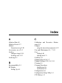
Index
iv
Mennen Medical
Chapter 1
What You Should Know
Intended Use of the EMS-XL System
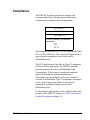
The EMS-XL is a computerized Cardiac
Electrophysiological Measurement System, designed for
conducting regular or experimental electrophysiology
(EP) studies.
The EMS-XL System is intended to be used for
performing computerized Cardiac Electrophysiological
and Ablation procedures.
The EMS-XL is intended for sale as a system for
performing Cardiac EP clinical studies.
Using the EMS-XL System
Before commencing patient monitoring, always perform
the following routine checks:
1. Check the system for signs of any mechanical damage.
2. Check all external leads, plug-ins and accessories.
3. Check all functions of the instrument needed to
monitor the patient and ensure that the system is in
proper working order
.
Do not use the EMS-XL System for any monitoring procedure on
a patient if you identify features which demonstrate impaired
functioning of the system.
Contact the hospital biomedical engineer, or a Mennen Medical Ltd.
service engineer.
Notes:
For recommended EMS-XL System cleaning procedures,
see General Cleaning Procedures on page 8-1.
For information on Calibration and Preventive
Maintenance on page 8-5.
Replacement of the CPU Battery
Whenever the EMS-XL System is disconnected from the
mains power supply, the CPU battery provides the back-up
power to the system set-up.
In the event that the system is disconnected from the mains
power supply for an accumulated period of 2 months (1440
hours) or more, or if it is only intermittently attached to the
power supply, the CPU battery should be replaced.
1-2
Mennen Medical
Compliance
The EMS-XL System is designed to comply with
(amongst others) the following international safety
requirements for medical electrical equipment:
IEC 60601-1
IEC 60601-1-2
IEC 60601-2-27
AAMI (voluntary performance
standards):
ES1
EC-11
The European Directive of 93/42/EEC classifies the EMSXL as a Class IIb device. The system is designed to have
special protection against electric shocks and is
defibrillator-proof.
The ECG application is classified as Type CF equipment
for direct cardiac application. The EMS-XL provides
protection against the effects of defibrillation and
electrosurgery. If the correct electrodes are used and
applied in accordance with the manufacturer’s
instructions, the screen display will recover within 10
seconds of defibrillation. Type CF equipment is designed
to have special protection against electric shocks
(particularly regarding leakage current) and is
defibrillator-proof.
For descriptions and locations of the symbols used on the
modules of the EMS-XL System, see Label Locations &
Symbol Descriptions on page 1-4.
EMS-XL User’s Guide
1-3
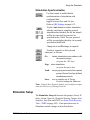
Label Locations & Symbol Descriptions
The following provides a short description of the meaning
of various labels and symbols that appear on the EMS-XL
System and identifies their location on the equipment.
Symbol
1-4
Description
Location
Attention, consult accompanying
documents. (Service to be performed by
qualified technician; consult Service
Manual before removing cover).
Isolation Transformer
and front and rear panels on Amplifier
ON
(power from mains power supply)
Power switch (Isolation Transformer front panel)
OFF
(power disconnected from mains power
supply)
Power switch (Isolation Transformer front panel)
Defibrillation – Proof
Type CF Applied Part
Amplifier - front panel (next to all
ECG-related connectors)
Earth
Isolation Transformer (rear panel)
AC Output
220-240V: 10A
Isolation Transformer (rear panel)
CE Approval by Notified Body
Manufacturer Identification Label (Isolation Transformer - rear panel)
Date of Manufacture
Manufacturer Identification Label (Isolation Transformer - rear panel)
Mennen Medical
General Use of Accessories
• Use only Mennen Medical-approved accessories with
the EMS-XL System. This includes - but is not limited to
- those accessories approved for use with the Vital Signs
Modules: ECG and IBP.
• Do not use a damaged accessory. Always refer to the
instructions for use included with each accessory.
• A disposable (single patient) accessory should not be
sterilized or cleaned for re-use.
• Use care when installing accessories such as adapters
and cables.
Do not use force. Do not cause tension in cables when
connecting them to the vital signs modules.
Environmental Specifications
Operation
Mode of Operation
Continuous use during EP study.
Humidity
10%-93%, non condensing
Temperature
5°C to 35°C (41°F-95°F)
Environmental Conditions for Transport and Storage
Temperature
-15°C to68°C (5°F-158°F)
Relative Humidity
10%-93%, non condensing
Atmospheric Pressure
700hPa to 1060hPa
For easy reference, a table showing the Environmental
Conditions and Situations to be Avoided is provided on
the next page.
EMS-XL User’s Guide
1-5
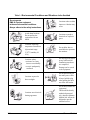
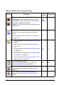
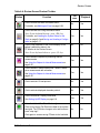
Table 1-1 Environmental Conditions and Situations to be Avoided
Do not operate
EMS-XL System equipment
in these environmental conditions.
Always adhere to the safety instructions.
1-6
Locations where sudden
impact or vibration may
occur.
Avoid damp locations.
Do not operate the
equipment with wet
hands.
Locations exposed to
chemicals or explosive
gases.
Locations with large
temperature fluctuations
(Operational range:
5-35oC; humidity 1093%)
Do not allow dust or
metal debris to penetrate
the monitors.
Locations where:
• moisture level may
increase considerably
• room is inadequately
ventilated
Do not plug in the mains
power cable until all
installation procedures
are completed.
Damage can be caused
to the equipment!
Locations exposed to
direct sunlight.
Do not pull directly on
the mains power cable.
Always hold the plug
when pulling the cable
out of the wall socket.
Locations near electrical
heating apparatus.
Do not dis-assemble the
equipment!
This should be done by
authorized personnel
only, otherwise Mennen
Medical Ltd. will not be
obligated to provide
technical service.
Mennen Medical
Where to Find Information
This guide contains the following additional chapters:
Chapter 2 - Warnings and Precautions: includes detailed
warnings and precautions you should adhere to.
Chapter 3 - Introduction: describes the main features and
the hardware of the EMS-XL system.
Chapter 4 - Getting Started: describes the Run Time and
Review screens and provides a short description of their
funcutionalities. In addition it describes logging in and out
of the application.
Chapter 5 - Setting Up Monitoring: describes how you can
setup the run-time display as well as other parameters that
can constitute a Configuration which you can save choose
to load for an EP study.
Chapter 6 - Performing the EP Study: describes the steps
involved in performing an EP study and how to perform
them.
Chapter 7 - Case Playback: describes the Case Playback
function which enables off-line review of a closed EP
Study.
Chapter 8 - Care and Maintenance: describes the routine
care and maintenance procedures and provides
recommendations for the frequency with which they
should be performed.
Chapter 9 - Offline Utilities: describes the available
offline utilities: Configuration Setup Utilitiy and Archive
Utility.
EMS-XL User’s Guide
1-7
1-8
Mennen Medical
Chapter 2
Warnings and Precautions
Prescription Notice
Federal United States law restricts the sale and use of this
instrument to qualified medical personnel only. In
addition, the user should be properly trained in the use of
the system. The instructions for use presented in this guide
should in no way supersede established medical protocol
concerning patient care.
Biocompatibility
All materials used in the patient cables and applied parts
have been tested for biocompatibility by the OEM
manufacturer(s) and are in compliance with the applicable
standards on biocompatibility.
The following information contains general warnings and
cautions for the user before initial use of the system.
Specific warnings and cautions pertaining to the operation
of part of the system or to an individual module, appear in
the relevant section of the manual.
Radiation
Radio frequency (RF) generates an electromagnetic field.
The intensity of the radiated field, at any point in space, is
directly proportional to the source of the voltage, and
inversely proportional to the distance from the source. In
the case of Ablation, the active electrode, return plate, and
their cables act as transmitting antennas.
Electromagnetic fields radiate perpendicular to their
associated cables. Therefore, susceptibility of the ECG
cable to this RF is maximum when the ECG cable is parallel
to the Ablation cable. Separating or placing cables
perpendicular to one another will minimize radiation
coupling effects.
In summary, radiation interference can be minimized by
the following:
• Using the lowest possible Ablation power setting.
• Keeping ECG cables as far from Ablation cables as
possible.
• Keeping ECG cables at right angles to Ablation cables.
Transducer Protection
Immunity requirements of IEC Collateral Standard 606011-2 for Electromagnetic Compatibility are met with the
transducers recommended for use with the unit.
SAFETY WARNINGS
A WARNING INDICATES A SITUATION IN WHICH
THE USER OR THE PATIENT MAY BE IN DANGER
OF INJURY OR DEATH.
Note:
This symbol is also used to signify a potential
risk of permanent loss of data.
Explosion Hazard
The equipment is not suitable for use in the presence
of flammable anesthetic mixture with air or with
Oxygen or Nitrous Oxide.
2-2
Mennen Medical
Electrical Shock Hazards
To eliminate the risk of electrical shock, always
adhere to the precautions shown below.
• Do not touch the patient, bed or instrument during
defibrillation.
• Before cleaning the monitor, switch the monitor OFF and
disconnect it from the power supply and electrical outlet.
After cleaning, or if liquid has accidentally entered the
interior of the monitor, make sure that every part of the
monitor is dry before reconnecting it the power supply.
See Chapter 8 - Care and Maintenance for more
information on cleaning the monitor.
• Access to any internal part of the EMS-XL System and/
or the performance of any service procedures should
only be carried out by a qualified technician, fully
trained in the operation of the system.
For continued protection against fire hazard, fuses should
be replaced only with those of the same type and rating.
Disconnect the power supply before servicing.
Risk of Permanent Loss of Data
To eliminate the risk of permanent loss of data, always
adhere to the procedure instructions provided in this
manual.
EMS-XL User’s Guide
2-3
CAUTIONS
A CAUTION INDICATES A SITUATION IN
WHICH THE UNIT, OR DEVICES CONNECTED
TO IT, MAY BE DAMAGED OR MALFUNCTION.
• The EMS-XL System is designed to conform to
Electromagnetic Compatibility (EMC) standard IEC
60601-l-2 and will operate accurately in conjunction
with other medical equipment which also meets this
requirement.
To avoid interference problems affecting the Monitor, do
not use Monitor in the presence of equipment which
does not conform to these specifications.
Note:
The term "Monitor" refers to both the EMS-XL
RT Monitor (Run Time) and the EMS-XL Review
Screen.
• Do not apply pressurized air to any outlet, or tubing
connected to the monitor. Pressure may destroy sensitive
elements.
• Do not store the system outside the specified
temperature range
(-20ºC to +65ºC [-4ºF to +149ºF]).
• Leave space for circulation of air to prevent the system
from overheating.
• Do not subject critical components of the system to
excessive heat, bending or magnetic fields.
• To prevent any liquid from entering the casing of the
display screen, do not tilt the display more than 45 degrees
backwards, or 15 degrees forwards, and ensure that the
display screen is not exposed to knocking and bumping.
2-4
Mennen Medical
• Dispose of the entire device, or parts of it, in accordance
with local environmental and waste disposal regulations.
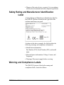
Safety Rating and Manufacturer Identification
Label
A Safety Rating and Manufacturer Identification label for
the EMS-XL System is located on the right side of the
isolation transformer rear panel.
As shown in the above example, the label includes the
following warnings and compliance information:
• Identification information:
Part Number (P/N), Serial Number (S/N), and model
name.
• Electrical power information: Voltage, Current, and
Frequency.
• Warnings: Disconnect supply before servicing.
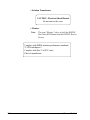
Warning and Compliance Labels
The EMS-XL System is fitted with warning and
compliance labels, located as follows:
EMS-XL User’s Guide
2-5
• Isolation Transformer:
CAUTION - Electrical Shock Hazard
Do not remove the cover
• Monitor:
Note:
The term "Monitor" refers to both the EMS-XL
Run Time (RT) Monitor and the EMS-XL Review
Screen.
Complies with DHHS radiation performance standards,
21 CFR subchapter J.
Complies with Part 15 of FCC rules.
Place of manufacture.
2-6
Mennen Medical
Chapter 3
Introduction
Overview
The EMS-XL is an advanced Electrophysiology Measurement
System designed for use by cardiac specialists as a diagnostic
aid when conducting electrophysiology (EP) studies on
patients, in a clinical situation.
This dual-monitor system has 32 channels (or 64 [optional])
and features an integrated two-channel programmable
stimulator, continuous Full Disclosure waveform storage, and
two invasive BP channels. In addition, pacing protocols are
integrated into the display and recording system.
Designed by EP professionals, the EMS-XL may be used for
performing computerized EP and ablation procedures and is
suitable for a variety of clinical applications. Ranging from
simple EP diagnostic investigations to complex cardiac
procedures.
The compact amplifier combines signal acquisition and
cardiac stimulation capabilities. Inherent flexibility of the
system, and easy-to-use stimulation protocols, enables the
EP specialist to view, measure and focus on events of cardiac
electrophysiological activity which occur either naturally, or
are induced via external stimulation.
EMS-XL User’s Guide
3-1
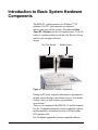
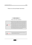
Introduction to Basic System Hardware
Components
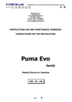
The EMS-XL system operates on a Windows® XP
platform. Two 20" color monitors are mounted
side-by-side on a central console. The dedicated Run
Time (RT) Monitor (on the left) displays up to 32 (or 64)
traces of continuous data in real time; the Review Screen
(on the right) displays still trace
images.
Run Time Monitor
Review Screen
Figure 3-1 Typical EMS-XL System Configuration
During an EP study, acquired information is presented in
graphic on-line displays (waveforms, traces), text format
(reports, lists), as well as hard copy printouts
(waveforms).
There are two options of the EMS-XL 32 and 64 channels.
For the 32 channel option the system is supplied with one
master amplifier, one patient box and a 10 lead surface
ECG patient cable.
For 64 channel option the system is supplied with one
3-2
Mennen Medical
Introduction to Basic System Hardware Components
master amplifier and one expansion amplifier with 4
patient boxes and a 10 lead ECG cable.
Channel Allocation
Each of the channels has gain control and an Invert switch.
The BP channels have a zero mode and calibration factor.
The EMS-XL has 64 channels with the following
characteristics:
Master Amplifier
Channels
Box
1 to 12
13 to 24
A 1-12
25
26
BP cable
27
28
Mode
Filter
ECG 12L
Selectable
Mono or
Bipolar
Selectable
Bipolar
40 Hz-Fixed
BP cable
29-32
40 Hz-Fixed
No gain
controls
BP
Bipolar
Stimulator
Output
No gain
controls
BP
Bipolar
Note
40 Hz-Fixed
Expansion Amplifier
Channels
Box
Mode
Filter
33 to 44
B 1-12
Bipolar
40 Hz - Fixed
45 to 56
C 1-12
Mono or
Bipolar
Selectable
57 to 64
D 1-8
Bipolar
40 Hz-Fixed
EMS-XL User’s Guide
Note
3-3
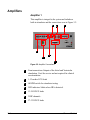
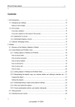
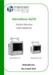
Amplifiers
Amplifier 1
This amplifier is integral to the system and includes a
built-in stimulator and the connections seen in Figure 3-2.
4
6
7
1
3
2
5
Figure 3-2 Amplifier Connections
3-4
1
Front connections Outputs of the Atrial and Ventricular
stimulation. Used for service and not required for clinical
use.stimulation.
2
1-12 surface ECG leads
3
60 BPM switch for stimulator testing
4
LED indicator- blinks when HR is detected.
5
13-24 ICECG leads
6
2 IBP channels .
7
27-32 ICECG leads
Mennen Medical
Introduction to Basic System Hardware Components
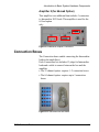
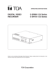
Amplifier 2 (for 64-lead Option)
This amplifier is an additional that includes 3 connectors
to Intracardiac ECG leads. This amplifier is used for the
64 lead option
only.
Figure 3-3 Additional Amplifier Connectors
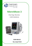
Connection Boxes
The Connection boxes enable connecting the Intracardiac
leads to the amplifier(s).
Each Connections box includes 12 plugs for Intracardiac
leads and a cable to connect between the box and the
amplifier.
• The 32 channel option- requires 1- 2 connection boxes.
• The 64 channel option- requires up to 5 connection
boxes.
Figure 3-4 Connection Box and cable
EMS-XL User’s Guide
3-5
EMS-XL Special Features
Comprehensive Full Disclosure
All sampled data is recorded during an EP study (Full
Disclosure [FD]). This enables viewing of the information
while the procedure is in progress, or during replay of the
session in Playback Mode.
Patient data is written to the hard disk throughout the case.
Note: For standard 32-channel systems, up to 16 hours per
patient may be recorded. On EMS-XL Systems with the
64 channel option, up to 8 hours per patient may be recorded.
During the case, snapshots may be saved as bitmap or
JPEG images for future presentation. At the end of the
case, all recorded study data may be archived to a DVD R/
W, a CD R/W or a magnetic optical disk (MOD).
Computerized Integrated Stimulator
Two channels of programmable stimulators with all basic
modes of pacing are integrated into the display. Also
featured are automatic increment/decrement functions
with triggered displays.
Continuous Case Log
The EMS-XL provides a window showing stimulation and
marker events to quickly locate a region of interest (ROI).
Clicking the associated event evokes display of the marker
in Full Disclosure context.
Reports
The EMS-XL provides an instantaneous laser printout of
all displayed traces or 12 lead printing (as selected), of
either the RT Monitor or the Review Screen. Measured
data and notes are automatically integrated into the fully
editable Microsoft Word® Report.
Additional Features and Functions
The EMS-XL System supports the following functions:
• Programmable Stimulator - pre-defined or user-defined
3-6
Mennen Medical
System Specifications
pacing protocols; Burst pacing; Autopace.
• Stimulation protocols library (can be customized and
extended).
• Playback of previous Case sessions.
• Event handling for both user-indicated events and
system-generated events enable quick zoom-in on
recorded information.
• Holter - enables minute-by-minute viewing of data
(in the Review Screen) and jumping to event.
• Snapshot capture storage (Bitmap format) - saved on the
local hard disk or DVD magnetic optical disk.
• Tachycardia detection - automatically detects onset of
arrhythmia according to user-defined preferences.
• Ability to extract part or parts of a previous case, using
time reference points (including all system and user
events: marked events and stimulator activities) and
save such data separately.
• Archiving of Full Disclosure (FD) information to DVD.
• SNRT (sinus node recovery time) automatically
calculated.
Offline Utilities
• Configuration Setup utility for editing registry entries for
EMS-XL configuration
• Archive utility for storing and restoring patient files.
EMS-XL Review Station - Complementary Product
(Optional)
The EMS-XL Review Station enables viewing and
playing back patient data files created in EMS-XL.
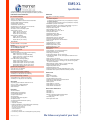
System Specifications
See the following pages for system specifications.
EMS-XL User’s Guide
3-7
^ƉĞĐŝĮĐĂƟŽŶ
A#$$$#*
**44*$$$*,$*#
(&(
7'*5**$6%
**$
!"#$%!! !!
&'(#$)*+*,$
-$"."/")01
".2!
3$45**$654%
**$
"$$#*%!! !!
+*$#7'"(3
"**47'
!8%*9
1:!8;*9
"
5!8%:*9
"**4"(
!8:*9
152!8!*9
"
%!82*9
$$$5!!*<#.$*
)
$$$7=7>?"!@
$8-*$9
*$
+3*$"**8' *$#9
1!!8
5*9
12!8
%
*9'$
5!!8*9'$
"2!855*9
"**8*$#*$9
!8%!*9
$*12!!85*9
$*";!!8;*9
-**1!8
5*9
-**"%!!85%*9
!"
!!)!/A6A6!>%!
5!)
!/A6%A6!
#$ %
7#B5B8
B=:B=9
#!:5*6*****
# %
7#)B%2B8B=2B=9
#!:5*6*****
$&
-*3$41*'CD
EFF=6/#$3#!!5
/"."E0+7C;
31!!;
&'
#$)*#$
#$$$*4#*
4*,$'.4$
$#*
+.*(*
$4#$$$#$,(
3*
/$##*
$
7$*
E*4.$,$4.#,$80=*9
A+370-5!!!6+7!!!8*3*49
EE!!78E.*$E*9
37-G+078*1,9
A7AG0EE8*9
A75!!38-(9
**.*C.#H*38,9
!#3-
!!:***$?A$$.34*#,J,*'#*
*+,-
3#4+62E*+8*$>$6%$9
./,-
3#4+6!E*+8
*$>$6%$9
"4,$$***,$
E*#"*0*I/((AAE+55
$**I5!!/AAE+55
E*#"-44I5!/
&=$*!>%!
4$!!6!6
!62!
?'4$!!
3$0$#*,
3$0!!!$>
*!%/>
*4**$
#**8,,,9
*0J*!*#
&5!K/
E*#E*L
$*0.M2
A,$*80=9=$*!!1
3#*0.M
(##0%
**$
E*#3*.K/>/>*#
#0*)!F5!!
N0*I!
7$"*0*)!!F
!
7*#+ *F/"6' *.4
**$
NA#I!
N"4?*I!*
#6**#
$#A#IIO6'.6
$#.4*#
$#?*1*O**
*0J*!!*#
"$3$0
2!
3$0$#*
,
=<#*0*-3$,$"
$#$/$#3$6"$**#
('$
#$)*
"#$**$##
F
#$
,$**$
A#*#$**** A#*4#$*
3&07$ #$1!)::
#$0*!)A6
!/
#$E*.$;!)::::
)'$1
$2
+&%!%!)
+&%!%!))
+&%!%!))
"4**$$(
)+6E+*EP7=
+(8!
;59
="AA.$G!;5
2
Chapter 4
Getting Started
This chapter describes the procedure for starting the EMS-XL
application (Starting the EMS-XL Application on page 4-1)
and exiting the application (Exiting the EMS-XL Application
on page 4-35).
It also includes the following:
• Run Time Monitor on page 4-5: A description of the Run
Time Monitor screen and its functionalities.
• Review Screen on page 4-15: A description of the Review
screen and its functionalities.
• Printing on page 4-34: Printing information.
Starting the EMS-XL Application
The system is supplied ready for use, therefore no special
set-up or installation procedures are required.
Note: In some situations, a user password may be necessary to
start the program (for example, when the EMS-XL system is
networked to a hospital information system). For user access,
contact your system administrator.
You need to check if your system has 32 or 64 channels ( One
or Two Amplifiers).
Note: Make sure that the program you are using is for 32 or 64
channels accordingly.
EMS-XL User’s Guide
4-1
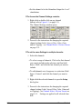
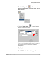
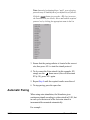
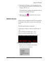
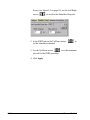
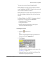
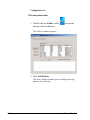
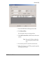
To check the number of amplifiers:
1. Right-click the EMS-XL Icon.
2. Select Properties.
3. Set the Target to :
"D\EPVersions\EmsOseRT_V1_1.37.exe" XX
Where 1.37 serves as an example of the software
version, and the value of XX is set according to the
number of amplifiers: If the system has one amplifier
XX=32, if two XX=64.
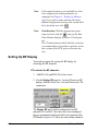
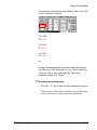
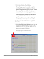
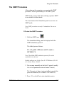
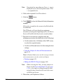
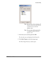
To Start the EMS-XL Program
• Double-click on the EMS-XL program icon
on the
Run Time Monitor desktop (the monitor standing on the
left).
The EMS-XL program starts running; the Run Time
Monitor opens with an initial display showing scrolling
waveforms (see 4-1), and the Review Screen opens
displaying still traces as shown in the example in Figure
4-3 Review Screen - Initial Display at Start-up on page 215.
The Run Time Monitor layout, menus, and tools are
described in the next section - see Run Time Monitor on
page 4-5.
An overview of the Review Screen layout, menus, and
tools is provided in Review Screen on page 4-15.
For a list of keyboard shortcuts, see Table 4-1 on page 43.
Note: For details on using the Run Time Monitor and Review
Screen during an EP study, see Chapter 6 - Performing the EP
Study.
4-2
Mennen Medical
Starting the EMS-XL Application
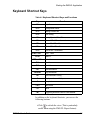
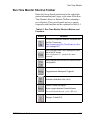
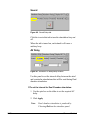
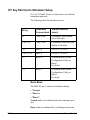
Keyboard Shortcut Keys
Table 4-1 Keyboard Shortcut Keys and Functions
Key
Function
<F1>
Help Screen
<F2>
Configuration Menu
<F3>
Pacing Protocol list
<F4>
Note Dialog
<F5>
Sweep Speed of Real-Time screen
<F6>
Zoom all Real-Time channels
<F7>
Freeze Real-Time Screen
<F8>
Print all Real-Time Screen
<F9>
Cont A 600 - Stimulation
CTRL+<F9>
Cont
600V
<F10>
Basic A
CTRL+<F10>
Basic V
<F11>
Burst A
<F12>
Burst V
<G>
Start Stimulation
<SPACE>
Stop Stimulation
<A>
Start Automatic Pacing
<C>
Display and cancel Caliper
<S>
Snapshot
<M>
Mark event
<T>
Timer
<B>
Toggle Big Numbers view for Stim window
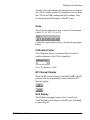
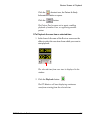
In addition to the keyboard shortcuts, you can use the
following buttons:
• Click
to refresh the view. (This is particularly
useful when using the EMS-XL Report feature).
EMS-XL User’s Guide
4-3
• Click
(Help) to see the basic EMS-XL commands.
• Click Open help file to open a PDF of the User
Manual
Note:Close the Help panel before trying to activate
any other function.
4-4
Mennen Medical
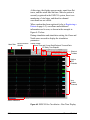
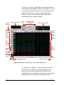
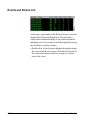
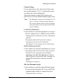
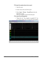
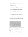
Run Time Monitor
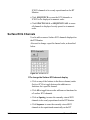
Run Time Monitor
The layout of the Run Time Monitor is designed to
provide effortless viewing of waveforms in Real-time
Mode. The greater portion of the Run Time Monitor
comprises the Traces Display (in the center). Above this,
the screen is divided into three main areas (see Figure 41):
• Heart Rate and BP/Ablation windows (left).
• Information panel: patient details, date & time (center).
• Traces Display controls, and shortcut buttons (right).
Heart Rate
Window
BP/Ablation
Window
Information Panel
Traces Display Controls
Shortcut
Buttons
Traces
Display
Status Indicators
Figure 4-1 EMS-XL Run Time Monitor - Initial Display at Start-up
EMS-XL User’s Guide
4-5
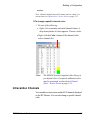
At this stage, the display appears empty, apart from flat
traces, and the actual date and time. Since no patient is
currently registered in the EMS-XL system, there is no
monitoring of vital signs, and therefore channel
waveforms are not visible.
When a patient has been registered (refer to Registering a
Patient on page 6-2), waveforms and additional
information can be seen, as shown in the example in
Figure-4-2 below.
During stimulation and stimulation setting, the Zoom and
Notch areas are used to display the stimulation
parameters.
Heart Rate
Blood Pressure /
Ablation
Patient Details
Actual Time and Current Date/Playback Time and Date
EP Study Time Elapsed
Shortcut
Toolbars
Surface
ECG
Channels
IntraCardiac
Channels
Status Indicators
Figure 4-2 EMS-XL Run Time Monitor
4-6
- Run Time Display
Mennen Medical
Run Time Monitor
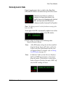
Hemodynamic Data
Patient hemodynamic data is visible in the Heart Rate
(HR) and BP windows located at the top left of the screen.
The heart rate (beats per minute) is
displayed in large green figures; the
smaller figure in red underneath is labeled
RR, and represents the RR Interval
(distance in mSec between R to R peaks).
*
Note: The flashing asterisk* on the left indicates sensing of the
heart rate (HR).
To the right of the HR, a dynamically-updated view of the
patient’s blood pressure is visible in the BP window.
Pressure values are shown in the following order:
Systolic/Diastolic/(Mean)
EMS-XL User’s Guide
Note:
If the BP display setting has not been enabled
from the Review Screen, BP values will not be
visible in the Run Time Monitor and the area
will appear blank. For details, refer to Setting
Up BP Display on page 6-8.
Note:
In Mennen Combo systems this area displays
SpO2 and NIBP measurements, if measured
from the patient. If the patient is connected to
both an Invasive Pressure line and a NIBP cuff,
only the IBP reading will show.
4-7
Ablation Data
Ablation results are displayed on the RT screen inside the
hemodynamic data window located at the top left of the
screen.
The following information is displayed:
• Temperature in Degrees Celsius (acceptable range: 1580).
• Power in Watts (acceptable range 1-150).
• Time in seconds (acceptable range 1-240).
• Impedance in Ohms (acceptable range 25-300).
Information Panel
Patient Details
To the right of the BP window, patient details are
displayed in an information panel (in the center of the
screen), in the following format:
First Name Last Name
Case ID
Note: Patient details are only displayed here when a case is
started, or when Play-back Mode is activated in the Review
Screen. In all other situations, these fields appear empty.
4-8
Mennen Medical
Run Time Monitor
Date and Time
Below the patient details, the information panel displays
the actual time and current date on the left, and the
elapsed time (since the start of the case) on the right.
Note: During Playback the elapsed time is relative to the
recorded elapsed time. Note, however, that since the playback is
at a different speed than real time it is different than the actual
elapsed time.
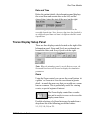
Traces Display Setup Panel
There are three display controls located on the right of the
Information panel: Zoom and Notch are positioned one
beneath the other, and Sweep Speed is on the right:
Note: When the stimulator panel is on the Review screen, the
Zoom and Notch area will be used to display the stimulation
parameters.
Zoom
Using the Zoom control, you can see the overall picture ‘at
a glance’ or Zoom in to view the waveforms in greater
detail - in much the same way that you would use a zoom
lens on a camera. This is particularly useful for viewing
events, or special regions of interest.
The Zoom display control has a combo
box and is used to increase or decrease the
display zoom factor.
Possible selections of a Zoom factor may be made from a
drop-down list of the following pre-defined values:
1:1; 1:2; 1:4; 1:8; or 2:1.
EMS-XL User’s Guide
4-9
Note: The selection list may not be edited, and the default value
is 1:1. This may be overwritten however, by loading any other
configuration. For details, refer to Loading the System Setup for
the Study on page 6-6.
Note: When selecting a Zoom factor, only the display of the
waveforms in the RT Monitor will be affected. The recorded
(FD) data will remain unchanged.
Sweep Speed
Sweep Speed is the rate (in mm/Sec.) at which the
waveforms are seen to move across the Traces Display (from
left to right). Increasing the Sweep Speed will influence the
Traces Display by making the waveforms move faster;
decreasing the speed will make them move slower.
There are six Sweep Speed control buttons, positioned
horizontally in one row and labeled (in mm/sec
[incrementing from left to right]), as follows:
Each of the six buttons provides exclusive selectivity. The
button corresponding to the currently-selected sweep
speed appears as pressed; all others appear normal (and
are ready for selection).
Note: The default Sweep Speed is 100 mm/Sec.
In Trigger Mode (only), any changes made to the Sweep Speed
will have an effect on the positioning of the vertical line displayed
on the RT Monitor.
Notch
The function of the Notch control is to enable or disable
the 50Hz Notch Filter on the EP-Box amplifiers.
The Notch control has two buttons: On and Off:
Note: The default value is ON. However. this may be
overwritten by loading any other configuration. For details,
refer to Loading the System Setup for the Study on page 6-6.
4-10
Mennen Medical
Run Time Monitor
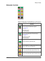
Run Time Monitor Shortcut Toolbar
Below the Sweep Speed controls and to the right of the
patient information panel (upper right corner of the Run
Time Monitor) there is a Shortcut Toolbar containing a
row of buttons. These provide quick access to various
frequently-used functions and are explained in Table 4-1.
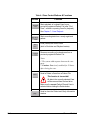
Table 4-1: Run Time Monitor Shortcut Buttons and
Functions
Button
Function
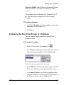
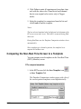
Provides a comparison between a template and
the Run Time screen.
See Comparing the Run Time Screen to a Template on page 6-57
Start, Stop and Reset Timer displayed on lower
bar of the RT screen.
Note: Keyboard <T> performs the same
function.
Save changes done online to the chosen screen
configuration.
Toggle between Sweep and Triggered.
Activates Calibration Pulse (1mV).
Used to Freeze the display.
Button toggles between Freeze/Unfreeze.
Or use keyboard shortcut - press <F1> key.
Displays 12 lead ECG.
EMS-XL User’s Guide
4-11
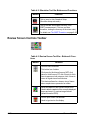
Table 4-1: Run Time Monitor Shortcut Buttons and
Functions
Button
Function
Activates 12 lead printout.
Activates displayed channels printout.
Activates Calipers
(used for performing interval measurements).
In Run Time Monitor: only available in Trigger
Mode.
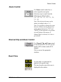
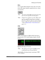
Traces Display
The waveforms visible in different portions of the Traces
Display, are as follows:
• Surface ECG channels
• Intra-cardiac channels
• BP channels
Surface ECG Channels
In Figure-4-2, traces from five surface ECG leads may be
seen at the top of the Traces Display. Each waveform is
labelled (on the right) with an associated channel.
Up to 12 channels (# 1 through 12) may be displayed here,
as required.
Intra-cardiac Channels
The next three rows of traces beneath those of surface
ECG (refer to Figure-4-2), show waveforms input from
the intra-cardiac channels.
Up to 20 (or optional 52) intra-cardiac channels (#13 and
onwards) may be displayed here. However, one or two of these
channels may be used for the display of BP signals, if required.
4-12
Mennen Medical
Run Time Monitor
BP Channels
Below the intra-cardiac waveform signals, there may be
one or two BP channels displayed.
Note: If you choose not to display BP channels, the lower
portion of the screen is used to display Intra-cardiac signals.
The total number of channels displayed in the Run Time
Monitor reflects the currently-selected settings. These
may be changed from the Run Time Monitor, using the
tools provided in the Review screen - see Setting Up
Surface ECG Channels on page 5-11 and Zoom Control
on page 4-33.
Note: The settings may also be changed by loading a pre-defined
(or customized) configuration setup. See Loading the System Setup
for the Study on page 6-6.
The word STIM is visible in green letters at the
top right corner of the Traces Display. This is associated
with anything displayed adjacent to (and on the left of)
this, and provides a visual indication of Stimulator Spikes.
When in Trigger Mode, a single, vertical white line is
visible on the Traces Display. All information displayed to
the right of this line represents the last (most recently
updated) beat.
Caution: Some of the software keys in the EMS-XL do
not show the active Status, but the Response to the
activation of the key.
Status Bar and Indicators
The Status Bar, located beneath the Traces Display and
extending the full width of the Run Time Monitor,
displays indicators showing general system information
and application modes, as described below (from left to
right).
EMS-XL User’s Guide
4-13
Disk Space
This window indicates how much free space is still
available on the system hard drive, during recording.
Warning: Do not allow the disk to be full - Delete files
when you reach 85 %
Note:
• When the disc reaches 85%, it will not be possible to
start a new case unless files are deleted.
• When the disc reaches 85% during a case, a warning
panel, that allows file delete will be presented.
• If the disc reaches 90% a warning panel will appear
every 5 minutes
• When the disc reaches 92% the case will be
terminated.
Paper Speed
Shows the currently-selected printer paper speed setting
(mm/sec).
Recording/Playback/Pause
This indicator shows the current system status and will
display one of the following:
• Playback - a recorded case is being played back
Note: if the indicator appears grayed out, Playback mode is
currently inactive.
• Recording - a case is being recorded
• Pause - a case is not being recorded to file.
4-14
Mennen Medical
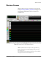
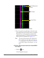
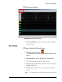
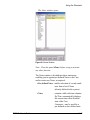
Review Screen
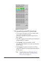
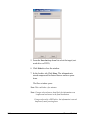
Review Screen
When the Review Screen is activated at system start-up
(refer to Starting the EMS-XL Application on page 4-1), it
initially opens displaying still traces as shown in the
example below.
Figure 4-3 Review Screen - Initial Display at Start-up
Note: The Review Screen is subject to the registration of a
patient - if no patient is currently registered, the screen will
show blank traces .
Once a patient has been registered, the Review Screen display
will appear as shown in the example in 4-4.
EMS-XL User’s Guide
4-15
The Review Screen is dedicated to the measurement and
uninterrupted manipulation of data and provides a view of
waveforms based on the Full Disclosure (FD) data. This
enables you to focus on events, control stimulation
protocols, perform measurements, and study various
relationships of the cardiac complex.
Stimulator
Parameters
Pacing Session Window
Stimulator
Controls
Parameter Setup and
Command Menus
Events and Stimuli Window
Review
Screen
Controls
Surface
ECG
Channel
Selection
Shortcut
Toolbar
Surface
ECG
Channels
Intracardiac
Channel
Selection
IntraCardiac
Channels
Reposition
Buttons
Zoom
Control
Channel
Clip/Zoom
Control
Ruler
(Time)
Scroll Event
Event Time
Scroll Backwards in Time
Scroll Forwards in Time
Figure 4-4 EMS-XL Review Screen - after Patient Registration
As can be seen in Figure-4-4, the greater portion of the
Review Screen comprises the Traces Display (in the
center); the areas above and to the left of the Traces
Display provide you with easy access to the various menus
and buttons, as described in the following sections.
4-16
Mennen Medical
Review Screen
Designed for the execution of programmed stimulation
protocols working with one or more extras, and in
conjunction with auto-snapshot, the Review Screen offers
a triggered display at up to 300 mm/sec, focused around
the last extra.
The last extra (or with shorter intervals, the last two
stimuli) is displayed, and the screen refresh is triggered
each time by the last extra.
A pair of electronic calipers is used to indicate the time of
atrial or ventricular activation, and the conduction time. In
combination with the automatic increment/decrement
mode of the stimulator, you can easily observe the
execution of the pace protocols.
Updating images is accomplished automatically at the end
of stimulation, or manually by clicking the Snapshot
shortcut button (described below). When the Calipers are
used to measure intervals, the measured intervals are
included in the final report.
When the mouse scrolls over a lead (in NRT) the
waveform changes its color temporarily to orange. This
makes the selected lead stand out from all the rest and
helps studying it.
EMS-XL User’s Guide
4-17
Upper Panel Controls
Help
The
icon on top, left of the Review screen provides
basic EMS-XL commands.
Pacing Session Window
The Pacing Session window is located at the upper left
corner of the Review Screen.
When the Stimulator is activated, this window provides a
useful view of the Pacing session and also indicates the
current pacing protocol.
Stimulator Parameters
The Stimulator Parameters are written in the 8 fields,
visible below the Pacing Session window. Here the current
Stimulator parameter settings are displayed, showing the
characteristics that have been defined via the Stimulator
Setup commands. The fields showing the output amperage
and length are read-only fields. The A and V channel
selectors are drop-down lists for choosing the channel
output.
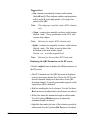
Note: For more details, see Using the Stimulator on page 6-15.
4-18
Mennen Medical
Review Screen
Stimulator Controls
Table 4-2: Stimulator Tool Bar Buttons and Functions
Button
Function
Click to access the Stimulator program.
See page 6-23.
Stimulation panel
Actual stimulation
Click to access Stimulator Threshold setup.
See page 6-21.
Stimulation threshold
Actual stimulation
Click to access the Last Stimuli tab
Click to access A-V coupling interval setup for stimulation of both Atrium and Ventricle.
Click to access Stimulator pulse (Atrium) setup.
Click to access Stimulator pulse (Ventricle) setup.
EMS-XL User’s Guide
4-19
Table 4-2: Stimulator Tool Bar Buttons and Functions
Button
Function
Click to jump to Auto Snapshot Setup
(Stimulator setup sub-menu).
Click to activate Sinus Node Recovery Time
(SNRT) measurement. (This is a one-time
procedure, testing the recovery of the sinus node).
For details see The SNRT Procedure on page 6-45.
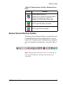
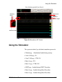
Review Screen Controls Toolbar
Table 4-3: Review Screen Tool Bar - Buttons & Functions
Button
Function
Controls trace thickness.
This button has 4 states:
Click once for thick trace lines on NRT; click
twice for thick lines on RT; click 3 times for thick
lines to appear on both screens; click 4 times to
return to regular trace line thickness.
This feature allows for a clearer view of traces
when snapshots are presented on slides.
Saves a snapshot of the Review Screen to file.
Used to take a snapshot of the currently-displayed
traces and save it in various image formats
(default format is JPEG).
Click to open Insert Text window.
Used to type text on the display.
4-20
Mennen Medical
Review Screen
Table 4-3: Review Screen Tool Bar - Buttons & Functions
Button
Function
Saves a partial Case to file.
Enables you to cut part of a case and create a
shorter case, saving it as a new file. For
example, cut 2 hours from a 5-hour study.
Click to open Stimulation List window.
Click to open Event List window.
Review Screen Shortcut Toolbar
The Review Screen Shortcut Toolbar is located below the
Command Menus and Events and Stimuli List - refer to
Figure-4-4. It contains a row of buttons that provide quick
access to frequently-used functions, as shown in Table 44.
Note: During playback and when no case is selected some of
the icons will be dimmed ( this means that the function is
unavailable.
EMS-XL User’s Guide
4-21
Table 4-4: Review Screen Shortcut Toolbar
Button
Function
Toggle between Holter and Study (Normal) view.
No
case
Playback
Yes
(only
Study)
Yes
Yes
Yes
Yes
Yes
No
Yes
Opens the QRS settings Tab to set the Heart Rate
source channel and settings. See QRS Settings on
page 4-25.
Yes
No
Click to access Channel Select commands. For
details, see Channel Select - Run Time Screen on
page 5-7.
Yes
Yes
Holter mode - Click to display one minute of single
lead (Default - lead II) at 25 mm/min. See Setting Up
BP Display on page 6-8 for details.
Study- Cancels the Holter view, returning the study to
normal view.
Provides a comparison between a template and
the Run Time screen on the right side of the NRT
screen.
See Comparing the Run Time Screen to a Template
on page 6-57.
• Opening a patient file: See Registering a Patient on
page 6-2.
• Add online Notes. See Adding On-line Notes on
page 6-48.
• Reports generator: See Editing the EMS-XL Report
on page 6-60.
• Exiting EMS-XL application. See Exiting the EMSXL Application on page 4-35.
• "Set up printing. See
Printing from the Run Time
Monitor Screen on page 6-51.
Click to add Notes to a Case.
Note: Or use keyboard shortcut - press <F3> key.
See Adding On-line Notes on page 6-48.
4-22
Mennen Medical
Review Screen
Table 4-4: Review Screen Shortcut Toolbar
Button
Function
Click to access the Mark commands menu.
No
case
Playback
No
Yes
For details, see Loading the System Setup for the
Study on page 6-6 and Saving and Loading a Configuration on page 5-17.
Yes
Yes
Click to copy snapshot of the current display of the
patient’s waveform status in the
RT Monitor to the Review Screen.
No
No
Yes
Yes
Yes
Yes
Click to activate 12 lead printout.
No
Yes
Click to activate displayed channels printout.
No
Yes
Yes
Yes
No
No
For details, see Marking an Event on page 6-28.
Click to access the Config commands menu.
Note: Or use keyboard shortcut - press <F4> key.
Note: Or use keyboard shortcut - press <S> key.
Click to activate Calipers for performing interval
measurements.
See Using the Calipers for Interval Measurements on
page 6-32 .
Click to activate Traces Location bar - used to associate a measurement with a location.
See Using the Calipers for Interval Measurements on
page 6-32.
Click to access BP Display commands.
See Setting Up BP Display on page 6-8.
Note: Available in Run-Time Mode only.
Click to stop saving Full Disclosure data to the system
hard disk. The FD button changes color and becomes
a red "stop sign".
Click again to resume saving FD data to the hard disk.
EMS-XL User’s Guide
4-23
Table 4-4: Review Screen Shortcut Toolbar
Button
Function
No
case
Playback
Note: Available in Playback Mode only.
Click to start playback of the event case from a time
selected in the lower left corner of the Review screen
No
Yes
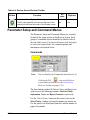
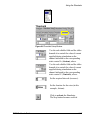
Parameter Setup and Command Menus
The Parameter Setup and Command Menus are centrally
located in the upper portion of the Review Screen. Each
group of commands can be identified by labelled tabs at
the top of the screen. Use the scroll arrows (left and right)
to access the required tab; the command groups and
functions are described below.
Commands
Note:
You can display the Commands menu directly by
clicking the File
icon on the Review
screen shortcut toolbar (see Review Screen
Shortcut Toolbar on page 4-21).
The three buttons on the left (Patient, Notes, and Report) are
used to access the following windows: Patient & Study
Information, Notes, and Report Generator, respectively.
Use the Select Printer button (in the center) to access the
Select Printer window to choose the printer you want to use.
Use the panel to set Print Speed (mm/sec) and the number of
pages to be printed.
4-24
Mennen Medical
Review Screen
Click the Exit button to quit the EMS-XL program (and
return to the Windows desktop).
See:
Registering a Patient on page 6-2.
Adding On-line Notes on page 6-48.
Editing the EMS-XL Report on page 6-60.
Printing on page 6-51
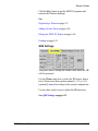
QRS Settings
This panel enables setting the channel from which the HR
will be measured.
Use the Chan.combo box to select the HR source from a
list of Surface and Intra-cardiac channels (1-32 or 1-64
[optional]), named according to the current configuration.
Use the other combo boxes to adjust the HR detection
See: QRS Settings on page 6-12
EMS-XL User’s Guide
4-25
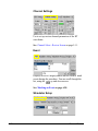
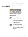
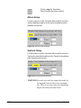
Channel Settings
Use to set up various channel parameters of the RT
waveforms.
See: Channel Select - Review Screen on page 5-11.
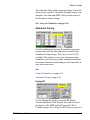
Event
Displays a list of Category names that are used to mark
events during the procedure. You can scroll through the
list, using the
up and down arrows
See: Marking an Event on page 6-28.
Stimulator Setup
4-26
Mennen Medical
Review Screen
The Stimulator Setup tab has nine sub-groups: Sound, AV
delay, atrium, ventricle, Threshold, Sensing Counter, Auto
Snapshot, Last Stim and SNRT. Each provides access to
the Stimulator control settings.
See: Using the Stimulator on page 6-15.
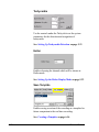
Stimulator Pacing
Used for conducting all pacing & stimulation protocols
and provides tools for achieving precise control of the
Stimulator Pacing settings. There are five sets (S1-S5)
available. The panel gives access to continuous/single
stimulation, sync/non-sync stimuli, automatic increment/
decrement stimulation and loading pre-saved protocols at
ease and in one screen.
See:
Using the Stimulator on page 6-15
Automatic Pacing on page 6-24
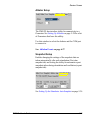
Display BP
Use the Display BP panel to set up the BP display:
Activate/Deactivate, Grid/No grid, Zero and to activate
the display of the NIBP and SpO2 from the CFE in
COmbo systems. See: Setting Up BP Display on page 6-8.
EMS-XL User’s Guide
4-27
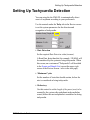
Tachycardia
Use the controls under the Tachy tab to set the system
parameters for the detection and recognition of
tachycardia
See: Setting Up Tachycardia Detection on page 5-21
Holter
Enables choosing the channel which will be shown in
Holter mode.
See: Setting Up the Holter Display Mode on page 5-22
Save Template
Enables saving a section of the recording as a template for
future comparison to the real time recording.
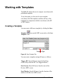
See: Creating a Template on page 6-56
4-28
Mennen Medical
Review Screen
Ablator Setup
The EMS-XL has interface ability for connectivity to a
Generator. See Setting Up Ablation on page 5-28 for a list
of Generators that have this ability.
Use this window to select the abalator and the COM port
to connect to.
See: Ablation Events on page 6-37
Snapshot Setup
Enables changing the settings of the snapshots that are
taken automatically after each stimulation (Post stim
snapshot tab) and setting the ability for automatic repeat
snapshots taken during stimulation and/or ablation (repeat
snapshot tab).
See Setting Up the Stimulator Auto Snapshot on page 5-26
EMS-XL User’s Guide
4-29
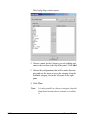
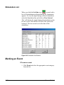
Events and Stimuli List
At the upper right corner of the Review Screen, a window
displays the Events and Stimuli List. This provides a
visual, time-referenced display of all events and stimuli
during the case. You can easily scroll through the list using
the scroll bar or up/down arrows.
• Double click a listed event to display the signals during
the event on the Review screen. Note that the left side of
the scale at the bottom of Review screen is set to the
time of the event.
4-30
Mennen Medical
Review Screen
Left Panel Controls
ECG and Intra-cardiac Channel Selection Buttons
These buttons control the channel set-up of the Review
screen.
Figure 4-5 ECG and Intracardiac Selection Buttons
To Display (turn ON) a Channel:
• Click on the required ECG / Intra-cardiac channel
button (or click ALL to display all channels).
To Remove (turn OFF) a Channel:
• Click on the appropriate ECG / Intra-cardiac channel
button (one that appears pressed) (or click ALL to
remove all channels).
EMS-XL User’s Guide
4-31
To change the color for the channel:
• Right-click the selected channel and select the new
color.
Reposition Buttons
Use Reposition buttons to control the
view of the currently-displayed
Surface ECG and/or Intra-cardiac
ECG channels
Click to re-position the channels
vertically and to re-distribute them
evenly on the screen.
Right-click arranges channels in
sequence with equal spacing.
Copy RT
Click Copy RT to copy the Run Time
screen channel setup to the Review
Screen.
4-32
Mennen Medical
Review Screen
Zoom Control
Use Zoom control combo box to
select required zoom option.
Selections may be made from the
following pre-defined values:
1:8; 1:6; 1:4; 1:3; 1:2; 1:1; 2:1;
3:1; 4:1.
Note: The selection list may not be
edited; the default value is 1:1.
Note: It is possible to change the zoom
directly (without entering properties)
of the channel by buttons "UP" and
"DOWN" of the keyboard, or by means
of scroll button of the mouse. If
channel label is selected, it's color is
grey/purple.
Channel Clip and Zoom Control
Use Channel Clip and Zoom control
to clip and zoom the view of a specific
Surface ECG or Intra-cardiac ECG
channel.
Click to access the appropriate
windows.
Event Time
Use the slider to set the time for
playback of a specific time.
The time from the start of the case is
displayed in the window.
EMS-XL User’s Guide
4-33
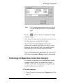
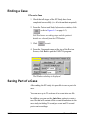
Printing
You can print from the Run Time Monitor screen (see
Printing from the Run Time Monitor Screen on page 6-51)
and from the Review (NRT) screen (see Printing from the
Review Screen on page 6-53).
Note: Due to difference in printer paper size and display size,
the printed page does not include the same information as the
display. A red marker at the bottom of the display indicates the
printer page end.
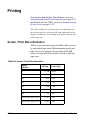
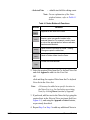
Screen / Print Size Information
Table 4-6 gives the time range (in milliseconds) covered
by one printed page under different printing speeds and
page sizes. It also presents the percetage of the NRT
screens in Study and Holter modes covered by different
page sizes.
Table 4-6: Screen / Print Size Information
Speed
mm/sec
4-34
A4 Page
Letter Page
25
11,200
10,400
50
5,600
5,000
100
2,800
2,500
150
1,900
1,700
200
1,400
1,300
250
1,100
1,000
300
950
~850
% from NRT Study screen
~70%
~63%
% from NRT Holter screen
~100%
~90%
Mennen Medical
Exiting the EMS-XL Application
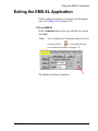
Exiting the EMS-XL Application
Before exiting the program you need to close the patient
case (see Ending a Case on page 6-64).
To exit EMS-XL
In the Commands menu at the top of the Review Screen
click Exit.
Note:
You can display the Commands menu directly by
clicking the File
icon on the Review
screen shortcut toolbar (see page 21).
The Windows desktop is displayed
EMS-XL User’s Guide
4-35
4-36
Mennen Medical
Chapter 5
Setting Up Monitoring
Before starting Medical Procedures it is possible to set-up
certain parameters according to specific EP Lab
requirements. These parameters are saved from patient to
patient and do not need to be changed after each procedure.
You can define the screen layout and channel settings and
save the settings in a Configuration file. The following
sections detail the procedures involved in building a
configuration and saving it:
• Setting Up Traces Display on page 5-2
• Channel Select - Run Time Screen on page 5-7
• Channel Select - Review Screen on page 5-11
• Setting Up Intra-cardiac ECG Channels on page 5-13
• Channel Settings on page 5-14
• Saving and Loading a Configuration on page 5-17
Additional setups are described in the following sections:
• Setting Up Tachycardia Detection on page 5-21
• Setting Up the Holter Display Mode on page 5-22
• Setting Up the Stimulator Auto Snapshot on page 5-26
• Setting Up Ablation on page 5-28
EMS-XL User’s Guide
5-1
Building a Configuration
You can build a Configuration file that includes the screen
layouts and channel settings. If you save this file you can
then load it and use it in future procedures.
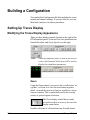
Setting Up Traces Display
Modifying the Traces Display Appearance
There are three display controls located on the right of the
RT Information panel: Zoom and Notch are positioned one
beneath the other, and Sweep Speed is on the right:
Note:
When the stimulator panel is used on the Review
screen, the Zoom and Notch area will be used to
display the stimulation parameters.
Zoom
Using the Zoom control, you can see the overall picture ‘at
a glance’ or Zoom in to view the waveforms in greater
detail - in much the same way that you would use a zoom
lens on a camera. This is particularly useful for viewing
events, or special regions of interest.
The Zoom display control has a combo
box and is used to increase or decrease the
display zoom factor.
Possible selections of a Zoom factor may be made from a
5-2
Mennen Medical
Building a Configuration
drop-down list of the following pre-defined values:
1:1; 1:2; 1:4; 1:8; or 2:1.
Note:
The selection list may not be edited, and the
default value is 1:1. This may be overwritten
however, by loading any other configuration.
For details, refer to Saving and Loading a Configuration on page 5-17.
Note:
When selecting a Zoom factor, only the display
of the waveforms in the RT Monitor will be
affected. The recorded (FD) data will remain
unchanged.
Sweep Speed
Sweep Speed is the rate (in mm/sec.) at which the waveforms
are seen to move across the Traces Display (from left to
right). Increasing the Sweep Speed will influence the Traces
Display by making the waveforms move faster; decreasing
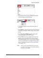
the speed will make them move slower.
There are six Sweep Speed control buttons, positioned
horizontally in one row and labeled (in mm/sec
[incrementing from left to right]), as follows:
Each of the six buttons provides exclusive selectivity. The
button corresponding to the currently-selected sweep
speed appears as pressed; all others appear normal (and
are ready for selection).
Note:
The default Sweep Speed is 100 mm/Sec.
In Trigger Mode (only), any changes made to
the Sweep Speed will have an effect on the positioning of the vertical line displayed on the RT
Monitor.
Notch
The function of the Notch control is to enable or disable
EMS-XL User’s Guide
5-3
the 50Hz Notch Filter on the EP-Box amplifiers.
The Notch control has two buttons: ON and OFF:
Note:
The default value is ON. However. this may be
overwritten by loading any other configuration.
For details, refer to Saving and Loading a Configuration on page 5-17.
Changing Channel Settings
In addition to modifying the general appearance of the
Traces Display, you can also change the number of
channels displayed (by adding or removing a channel from
the display), reposition a channel, make changes to the
channel settings and select the channel for stimulation
output.
Note:
When a channel is selected, it becomes grey in
color to indicate that it is the currently-selected
channel.
To add or remove a channel from the Run Time display:
• Refer to the Channel Select - Run Time Screen
instructions on page 5-7.
Note:
The channel display/hide commands for the RT
Monitor can only be executed from the Channel
Select window, accessed from the Review
Screen.
To Reposition a channel:
1. Click on any channel button (see Figure 5-1) and hold
down while dragging the button up or down.
2. Release the mouse button; the channel (and its
corresponding button) remains in the new position.
5-4
Mennen Medical
Building a Configuration
Channel Button
Channel Identification Label
(may be edited)
Physical Channel Number
(relates to patient connection
board; may not be changed)
Figure 5-1 Channel Buttons and Labels
Note:
It is possible to arrange the channels with equal
spacing or in sequence. See Channel Select Run Time Screen on page 5-7 for details
Each channel has pre-defined settings (as supplied with
the system). However, right-click access to the Channel
Settings controls enables you to make any of the following
changes to the currently-selected channel, as required:
• Change the Name of a channel identifier label
• Invert the displayed polarity of a channel
• Change High Pass Filter
• Change Polarity - Bipolar to Unipolar (or vice-versa)
• Set the Gain
Note:
It is possible to change the gain without entering Channel Setting. Click with the mouse on the
channel and use the mouse scroller (up/down)
or keyboard keys ( up/down) to change the gain.
• Change the Color of a channel
• Perform Clipping of traces
EMS-XL User’s Guide
5-5
• Set the channel to be the Stimulator Output for A or V
stimulations
To Access the Channel Settings controls:
1. Right-click or double-click on any channel
button (refer to Figure 5-1 on page 5-5).
The Channel Settings window opens:
2. Proceed to the instructions for changing the required
channel setting (Label, Invert, Filter, Color, Gain,
and/or Clipping) - see Channel Select - Review Screen
on page 5-11.
To set the same Settings to multiple channels:
1. Select the channels:
• To select a range of channels: Click in the first channel
you want to include in the selection, and then hold
down <Shift> and click the last channel you want to
include.
• To add channels out of sequence to a selection: Hold
down <Control> and click the channel you want to
add.
2. Right-click the selected channels to open the Setup
dia-log box.
3. Proceed to the instructions for changing the required
channel setting (Label, Invert, Filter, Color, Gain,and/
or Clipping) - see Channel Select - Review Screen on
page 5-11. Settings are applied to all selected channels.
5-6
Mennen Medical
Building a Configuration
Channel Select - Run Time Screen
The left side of the RT Channel setup panel for RT
screen window contains two groups of selection controls:
Surface ECG (on the left), and Intra-cardiac ECG (on the
right).
The right side of the RT Channel setup panel for RT
screen window contains the list of the Active RT channels
with fields that enable changing the Label, Filter, Polarity,
Gain and Color of the channels.
Figure 5-2 Channel Setup Panel
• Click SPACING to cause the currently-viewed ECG or
EMS-XL User’s Guide
5-7
ICECG channels to be evenly repositioned on the RT
Monitor.
• Click SEQUENCE to cause the ECG channels or
ICECG to be displayed in numeric order.
• Click SPACING ALL or SEQUENCE ALL to cause
all channels to displayed evenly spaced or in numeric
order.
Surface ECG Channels
Used to add or remove Surface ECG channels displayed on
the RT Monitor
Also used to change a specific channel color, as described
below.
Figure 5-3 Surface ECG
To change the Surface ECG channel display
• Click on any of the buttons in the three columns (under
Surface ECG) to toggle between the add/remove
functions for a specific channel.
• Click All to toggle between the add/remove functions for
all surface ECG channels.
• Click on Spacing to cause the currently-viewed ECG
channels to be evenly repositioned on the RT Monitor.
• Click Sequence to cause the currently-viewed ECG
channels to be repositioned numerically on the RT
5-8
Mennen Medical
Building a Configuration
monitor.
Note: Channel identification label names may be edited - for
instructions see Channel Select - Review Screen on page 5-11.
To change a specific channel color:
1. Do one of the following:
• Right-click a currently-activated channel button. A
drop down palette of colors appears. Choose a color.
• Right-click the Color column of the channel in the
active channels list.
Note:
The EMS-XL System is supplied with a library of
pre-defined colors. If required, additional colors
may be customized, as described in Channel
Select - Review Screen on page 5-11.
Intracardiac Channels
You can add or remove intra-cardiac ECG channels displayed
on the RT Monitor. You can also change a specific channel
color.
EMS-XL User’s Guide
5-9
Figure 5-4 Intracardiac ECG.
To change the Intracardiac ECG channel display
• Click on any of the buttons in the four columns (under
Intracardiac) to toggle between the
add/remove functions for a specific channel listed in
those columns.
• Click All to toggle between the add/remove functions for
all Intracardiac ECG channels.
• Click Spacing to cause the currently-viewed
Intracardiac ECG channels to be evenly repositioned on
the RT Monitor.
• Click Sequence to cause the currently-viewed Intra
cardiac ECG channels to be repositioned numerically on
the RT monitor.
Note:
5-10
Channel identification label names may be
edited; for instructions, see Channel Select Review Screen on page 5-11.
Mennen Medical
Building a Configuration
Note:
One or two Intra-cardiac channels (physical
channels 26 and 28 only) may be used for BP
display, if required. By default, these are
labelled Pr1 and Pr2.
To change a specific channel color:
• Right-click on any channel button or right-click on the
Color column of the channel in the active channels list
and select the required color from the pre-defined colors.
The button background color changes in accordance
with your selection.
Note:
Colors available for selection may be customized under the Channel Select - Review Screen
tab - see page 5-11
Channel Select - Review Screen
Setting Up Surface ECG Channels
Figure 5-5 ECG Channel Selection Buttons.
To Display (turn ON) a Channel:
• Click on the required ECG channel button (or click
ALL to display all channels).
EMS-XL User’s Guide
5-11
To Remove (turn OFF) a Channel:
• Click on the appropriate ECG channel button (one
that appears pressed) (or click ALL to remove all
channels).
Note:
Buttons for currently-selected channels will
have a pressed appearance; inactive channel
buttons appear normal. Buttons toggle ON/OFF.
To Change a Channel Color:
1. Right-Click on a currently-activated channel button.
The button changes to a new color.
2. Click again to "scroll" to the next color (as
pre-defined in the system).
3. Repeat Step 2 until the required color is selected.
The EMS-XL System is supplied with a library of
pre-defined colors. If required, additional colors may be
customized, as described in Channel Select - Review
Screen on page 5-11
5-12
Mennen Medical
Building a Configuration
Setting Up Intra-cardiac ECG Channels
Figure 5-6 Intra-cardiac Channel Selection Buttons.
To Display (turn ON) a Channel:
• Click on the required channel button (or click ALL to
display all channels).
To Remove (turn OFF) a Channel:
• Click on the required channel button (or click ALL to
remove all channels).
Note:
Buttons for currently-selected channels will
have a pressed appearance; inactive channel
buttons appear normal. Buttons toggle On/OFF.
To Change a Channel Color:
1. Right-click on a currently-activated channel button.
The button changes to a new color.
2. Click again to scroll to the next color (pre-defined in
the system).
3. Repeat Step 2 until the required color is selected.
EMS-XL User’s Guide
5-13
Note:
The EMS-XL System is supplied with a library of
pre-defined colors. If required, additional colors
may be customized, as described in Channel
Select - Review Screen on page 5-11
Channel Settings
Figure 5-7 Channel Settings
Label contains an editable field, to enable
renaming of the currently-selected Channel
Identification Label (Figure 5-1 on page 55.
• Click in the field and type the required
name over the existing label name.
Note: You can enter up to
5 characters only.
Click Invert ON or OFF to mirror the
channel polarity, as required. Changes the
displayed polarity of the currently-selected
channel.
Note: FD data is unaffected; the default
setting is OFF.
5-14
Mennen Medical
Building a Configuration
Each channel has its own pre-defined default
High Pass Filter setting (as supplied with the
system). However, the setting may be
changed, if required.
Note: By default, 0.05 and 0.2 are unipolar; 40 and 80 are bipolar.
Channels 1 to 12 are Surface leads and are
not effected by the Unipolar/Bipolar
switches
Channels 13 to 24 and Channels 45 to 56
are switchable between Bipolar and
Unipolar. Channels 25-32, 33 to 44 and 57
to 64 are Bipolar channels .In Unipolar mode the (- ) black
sockets will be used as reference. The reference is the
Wilson reference of the surface limb leads
Note:
Filters -- Channels 25 to 32, 33 to 44, and 57 to
64 have fixed High Pass filters of 40 Hz
• To change the Filter for the currently-selected channel,
activate the appropriate radio button (0.05, 0.2, 40 or
80Hz).
• To change the polarity, click the associated button
(Bipolar [B] or Unipolar [U]).
Buttons toggle between
and
.
Gain contains an editable text field used to edit
the gain value (0-255) of the currently-selected
channel in the RT Monitor.
In addition, a slider vertically positioned beneath
the edit field, points to a row of gain value marks
on the right. Moving the slider up or down
changes the value in the text field above. Similarly, any
editing of text in the edit field will automatically change the
slider to the position corresponding with the new value
(0 at the bottom; 255 at the top).
EMS-XL User’s Guide
5-15
Color provides the tools for color customization
of colors.
Three movable sliders (labeled R, G, and B
[red, green, blue]) - are used to define the
colors available for selection in the system.
To define a new color:
1. Drag the R, G, and/or B, slider until the
required color is displayed in the bar above.
2. Click Set to save the color setting.
Note:
To change the color of a currently-selected
channel, it is recommended to refer to the
instructions for Channel Select - Run Time
Screen on page 5-7.
Clipping is used to control the amount of
clipping applied to the currently-selected
channel in the RT Monitor and to prevent
overshooting of traces.
Note: An overshooting trace (i.e., one
that overshoots to the neighboring
trace) may be clipped to prevent it
from overwriting another channel.
The Clipping[%] controls are two pairs of editable fields
and sliders. The pair on the top defines (by percentage) the
clipping applied above the currently-selected channel; the
pair below defines the clipping applied below the
currently-selected channel.
Radio buttons indicate whether clipping is enabled (ON)
or disabled (OFF) for the currently-selected channel.
Note:
5-16
By default, the channel clipping is set to OFF
and 0% is displayed in the editable fields.
0% means no clipping, 100% means full clipping.
Mennen Medical
Building a Configuration
To activate channel clipping:
1. Activate the ON radio button.
2. Click and drag the upper or lower slider (as
appropriate) to the required position.
The percentage of clipping to be applied to the channel
(above or below) is shown in the corresponding field.
Saving and Loading a Configuration
The Channel set-up shortcut
in the Review screen
toolbar, opens a window for Config Select that displays
text items (listed alphabetically) which are configuration
file names used to Load or Save entire screen layouts and
channel settings. .
To open a defined configuration setting:
1. Do one of the following:
• Press the Configuration
toolbar button and
choose a Configuration or Category/sub-config from the
menu that opens.
EMS-XL User’s Guide
5-17
• Click the Channel set up
. toolbar button to
open the Channel set-up panel.
Click or scroll through the Config Select list, using the
up and down arrows, to choose a pre-configured
configuration.
Press Load.
Press CLOSE to close Channel-set-up panel.
To save a newly-defined configuration setting to the
system hard drive:
1. Click the Channel set up
open the Channel set-up panel.
toolbar button to
2. In the textbox at the bottom of the pane, type the chosen name for the new configuration.
5-18
Mennen Medical
Building a Configuration
Note:
If the configuration name already exists in the
system, the Save button will be labeled Overwrite.
Use the
button to delete a configuration setting
from the system.
Note: Some file names may not be deleted, in which case
the Delete button is automatically disabled.
The currently-selected configuration file name is
displayed in an editable text field under the list control.
Editing the text in this field will create/modify the file
name when the Save/Overwrite button is pressed.
A new configuration name appearing in the selected text
field causes the Load and Delete buttons to be disabled.
Combining Configurations Under One Category
It is possible to combine several configurations under a
common Category name (for instance the Category
AVNRT will include a configuration for diagnosis and
another configuration for ablation.)
To build a category:
1. In the Channel set-up panel press Categories (see Figure 5-2) .
EMS-XL User’s Guide
5-19
The Config Setup window opens.
2. Choose a name for the Category you are building and
enter to the text box at the top of the panel. Click Add.
3. Choose the configurations that will be under this category and use the arrow to move the category from the
available category list (in the left pane) to the right
pane.
4. Click Close.
Note:
5-20
It is also possible to choose a category form the
drop down list and edit its contents or to delete
it.
Mennen Medical
Setting Up Tachycardia Detection
Setting Up Tachycardia Detection
You can setup the the EMS-XL to automatically detect
onset of arrythmia according to your preferences.
Use the controls under the Tachy tab in the Review screen
to set the system parameters for the detection and
recognition of tachycardia.
• Rate Detection
Set the required Rate Detection value (in msec).
A Heart Rate faster than this (for example, 120 BPM) will
be considered by the system as being tachycardia. When
this occurs, an event named "Tachycardia" will be added
to the Events and Stimuli List (seen at the upper right
corner of the Review Screen - refer to the next page).
• Minimum Cycles
Set the number of beats that should sustain, before the
rate is considered as being tachycardia.
• Refractory
Use this control to set the length of the pause (secs) to be
counted by the system after arrhythmic tachycardia has
ceased, before the next arrhythmia is considered as being
tachycardia.
EMS-XL User’s Guide
5-21
Setting Up the Holter Display Mode
The Holter Display mode enables minute-by-minute
viewing of data in the Review (NRT).
Change to Study (Display) Mode
Waveform (WF) Area
Selected Range
Holter Area
Navigation Buttons
The Holter Display mode divides the Review screen (NRT
screen) into 2 areas: Holter area (about 30 % of original
NRT screen at right side) and Waveform (WF) Area
(about 70 % of original NRT screen at left side) that
displays WF channels in the same way as during
StudyDisplay mode.
5-22
Mennen Medical
Setting Up the Holter Display Mode
The Waveform (WF) Area
The WF Area is the same as in Study Display mode in the
Review (NRT) screen with two exceptions:
• There is no navigation scroll bar - Navigation is done in
the Holter area.
• Trace location cannot be modified by dragging the
channel labels. You need to return to Study Display
mode in order to modify trace locations.
Note: Calipers activities in the WF area are the same as in Study
Display mode in the Review (NRT) screen.
Holter Area - Description
The Holter area displays 1 minute of single channel WF
data of a specific channel (defined in the Holter window).
The one minute Holter display start at the beginning of the
minute selected on the Review screen (bottom left of the
screen).
This waveform is displayed in 25 mm/sec divided into 12
lines, each showing 5 seconds of a single channel WF
data.
Two red markers [ and ] on the Holter area, show the
selected Holter range. The selected range width depends
on the WF Area sweep speed (see Figure 2-11).
The distance between the brackets [ ] is equal to the
length of the WF area, that is for example:
• About 12 seconds in 25 mm/sec
• About 6 seconds in 50 mm/sec
• About 3 seconds in 100 mm/sec
Any change of the selected area presents the
EMS-XL User’s Guide
5-23
corresponding multi-lead waveforms in the WF Area.
Stimulation Events are shown on both the Holter and the
WF area by magenta markers on the Holter waveform and
on the top of the WF area.
Holter Area Navigation
You can move the selected range by setting the Start, End
or Middle position of the range. You can also use the
navigation buttons to move the range back or forward in
steps, to another line or to the beginning or end of a page.
To set the selected Holter area:
1. Do one of the following:
• Set the Start position: Select the Start position of the
brackets ([) in Holter area and click the mouse.
• Set the End position: Select the End position of the
brackets (]) in Holter area and right-click the mouse.
• Set the position of the middle of the range: Select a
middle position of the brackets in the Holter area and
while holding down <Ctrl> click or right-click the
mouse.
To move the selected Holter area:
1. Use the navigation buttons at the bottom of the Holter
area in the Review screen (see Figure 2-11):
Move the brackets to previous / next data in
Holter area . Each step is about 1/12 of the
WF area duration:
• Click the mouse to move one step forward or backward
(1 second if WF area speed is 25 mm/sec).
• Right-click the mouse to move 2 steps forward or
5-24
Mennen Medical
Setting Up the Holter Display Mode
backward (2 seconds if WF area speed is 25 mm/sec).
Move to previous / next line in Holter area.
• Click the mouse to move one page forward or
backward (Start of new brackets at the end of the
previous brackets). (about 11.5 seconds with WF area
speed of 25 mm/sec).
• Right-click the mouse to move move 1 line forward or
backward (5 seconds with WF area speed of 25 mm/
sec.).
Note: New 30 seconds are loaded automatically when the
brackets cross the limit of the Holter displayed minute.
To change to Study Display mode / Holter mode:
1. Click the Study Display mode button
to
change from Holter mode to Study Display mode.
2. Click the Holter mode button
Study Display mode to Holter mode.
to change from
Changing from one mode to another keeps the same time
location and view.
Note: If calipers are active they are removed when changing
from one mode to another.
EMS-XL User’s Guide
5-25
Setting Up the Stimulator Auto Snapshot
The Post stim Snapshot tab enables you to
control the automatic snapshot settings in use
when the Stimulator is activated.
This feature is particularly useful for measuring
refractoriness, where the Review Screen is
triggered by the last stimuli. The triggered display
is continuously refreshed by the last extra
premature stimulus.
A pair calipers is used to indicate the time of Atrial
or Ventricular activation, as well as the conduction
time. In combination with the automatic
increment/decrement mode of the Stimulator, you
may easily observe the execution of the pace
protocols. The RT Monitor running display
monitors the patient, and gives information about
the capture of the stimuli; the triggered portion
represents the conduction time differences in
full-time resolution.
Use this control to set Automatic
Snapshot ON or OFF.
5-26
Mennen Medical
Setting Up the Repeat Auto Snapshot
Sets the position of the last stimulus (mm).
Sets the sweep speed
(msec).
Sets the delay after stimulation (the
number of secs required to delay the
autosnapshot after capturing).
When all the above-mentioned settings
are correct, click OK.
Setting Up the Repeat Auto Snapshot
The Repeat Snapshot tab enables you to set up auto
snapshots (shown on the NRT screen) every X seconds
during the ablation and/or stimulation and/or free time.
• For automatic snapshots during the study: Check
Free Time, and enter the interval at which automatic
snaphots are taken during the study.
• For automatic during any ablation event: Check
Ablation, and enter the interval at which automatic
snaphots are taken during any ablation event.
• For automatic during any stimulation event: Check
Stimulation, and enter the interval at which automatic
EMS-XL User’s Guide
5-27
snaphots are taken during any stimulation event.
Setting Up Ablation
The EMS-XL has the ability to connect to a number of
ablators (generators). Connection to ablators enables
seeing the ablation data on the EMS-XL screen during the
ablation as well as a graph of the data and printing this
data. It is possible to change the ablator and COM port
from the application.
The ablators that connect to the EMS-XL are :
• MAESTRO 3000 (Boston Scientific)
• IBI 1500T (Irvine Biomedical Inc)
• STOCKERT (Biosense Webster)
• EPT 1000 (Boston Scientific)
• ATAKR II (Medtronic)
• HAT 300 Smart (OSYPKA)
To set up ablation:
1. Click the Ablation setup tab.
2. Choose the COM port to which the ablator is connected.
5-28
Mennen Medical
Setting Up Ablation
3. Choose the type of abaltor (generator) connected.
4. Click Apply.
EMS-XL User’s Guide
5-29
5-30
Mennen Medical
Chapter 6
Performing the EP Study
EP Study Overview
Performing an EP Study consists of the following:
• Registering a patient (see Registering a Patient on page 6-2)
• Setting up the EP study parameters. You can start by
loading a saved configuration or start a new setup.(see
Setting Up a Procedure on page 6-6)
• Using the Stimulator and selecting the required pacing
protocols (see Performing Stimulation on page 6-23)
• Performing the study.
• Ending the case (see Ending the EP Study on page 6-60).
In addition you can add notes (see Adding On-line Notes on
page 6-48) and print the RT and the NRT screens (see
Printing on page 6-51). You can also compare the Run Time
waveforms with a pre-defined template (see Working with
Templates on page 6-56).
After ending the case you can cut part of a case and create a
shorter case, saving it as a new file (see Saving Part of a Case
on page 6-64).
EMS-XL User’s Guide
6-1
Registering a Patient
An EP study begins with patient registration. After this,
the study procedures should be continued in the order
given in the subsequent sections.
To register a patient
1. From the Command menus at the top of the Review
Screen, scroll to the Commands tab.
2. Click
Patient:
Note: Alternatively, click the
shortcut icon (instead of
performing Step 1 and Step 2, above).
The Patient & Study Information window opens, as
shown in Figure-6-1. The window has four main areas:
• Patient General Information
• Study-related Information
• Patient Tree
• Case Control Buttons
6-2
Mennen Medical
Registering a Patient
Current
Patient
General
Information
Study
Information
Patients
Registered
in the System
Case
Control
Buttons
Figure 6-1 Patient and Study Information Window
Note:
EMS-XL User’s Guide
For an explanation of the Case Control buttons,
refer to Table 6-1.
Click Done to close the panel before trying to
activate any other function
6-3
Table 6-1 Case Control Buttons & Functions
Button
Playback
Case
Function
Starts playback of a closed Case from a
previously-registered Patient File (after "End
Case", enables re-opening Case for playback).
See Chapter 7 - Case Playback
Starts recording data from a newly-registered
patient.
End
Case
Ends (closes) the current Case
(both in Real-time and Playback modes).
Resumes recording of a closed case from a
previously-registered Patient File.
Notes:
1. The system adds a pause between the case
parts.
2. Continue Case is only enabled for 24 hours
after closing the case.
Used to Delete a Case from a Patient File.
Delete
This function is irreversible!
All data in the currently-selected Case
will be removed from the hard drive.
Make sure the correct Patient File and Case is
selected before clicking the Delete button.
Used to close the Patient and Study Information
window.
6-4
Mennen Medical
Registering a Patient
3. Enter the appropriate details in the Patient General
Information data input fields, as shown below
E.
Asherton
Note: There are four fields for which entering information
is obligatory (see below); all other fields are optional:
• Patient First Name
• Patient Last Name
• Patient I.D.
• Case I.D.
Note: When entering the Case I.D., if a separator is
required, use underscore and not dash. For example,
case #276 of year 2003 should be written as 276_2003.
Activate the relevant radio buttons: Weight, Height,
and Sex.
4. Under the Study Related Information select the required
Study Type. For example, General, Syncope, VT,
WPW, VF, etc.
Note:
EMS-XL User’s Guide
The Study Date is automatically inserted on
Start New Case.
6-5
Enter additional information, as required (Faculty,
Fellow, Technician, Physician).
5. Check that all details entered in the window are correct,
then click the
button.
The patient is now registered in the system.
The timer starts.
The recording of Full Disclosure data onto the hard
disk commences.
In the RT Monitor, the newly-registered Patient details
are displayed in the Information panel (center, top of
the screen - refer to Figure-4-2 ).
Note: The Patient & Study Information window remains
open.
6. Press Done.
Setting Up a Procedure
Loading the System Setup for the Study
The setup procedure is required to configure the EMS-XL
System with a setup appropriate for the specific study.
Note:
Some studies may require more channels, and
others (basic studies) will require less channels.
System setups can be loaded using either the Configuration
command, or simply tailored manually for the particular
case.
To load the system setup for the study
1. Do one of the following:
6-6
Mennen Medical
Setting Up a Procedure
• Press the Configuration
toolbar button and
choose a Configuration or Category/sub-config from the
menu that opens.
• Click the Channel set up
. toolbar button to
open the Channel set-up panel.
Click or scroll through the Config Select list, using the
up and down arrows, to choose a pre-configured
configuration.
Press Load.
Press CLOSE to close Channel-set-up panel.
EMS-XL User’s Guide
6-7
Note:
If the required setting is not available for selection, configure the system parameters, as
required (see Chapter 5 - Setting Up Monitoring). If you wish to name and save the newlydefined configuration setting to the system hard
drive for future use, click Save .
Note:
Print Baseline: With the appropriate system
setup selected, click the
icon (on the Run
Time Monitor display) to print a 12-lead printout.
The 12-lead printout (called ‘baseline’ printout)
is recommended as it provides a reference of the
basic status of the ECG, prior to the intervention.
Setting Up BP Display
You need to prepare the system for BP display by
activating the BP channels.
To activate the BP channels:
1. Add PR1 (26) and PR2 (28) to the screen.
2. Use the Display BP panel to: Activate/Deactivate BP
display, Grid/No Grid, Zero, Activate/Deactivate CFE
connection.
The Display BP tab is used to configure the two BP
channels (Pr1 and Pr2). Once they have been configured,
they are permanently displayed in the lower portion of the
RT Monitor (Figure-4-1), below the intra-cardiac channels.
6-8
Mennen Medical
Setting Up a Procedure
The tab is also used to display the parameters received from
the CFE in a Combo system. The parameters received from
the CFE are the NIBP readings and SpO2 readings. They
are displayed in the BP window of the RT screen.
Scale
The grid scale ranges from zero, to one of five maximum
values: 25, 50, 100, 125, or 250.
Choose the required grid scale by clicking the appropriate
button.
Calibration Factor
The Calibration Factor is a numeric field, provided to
enable calibration of the EP-box (amplifier).
Note: The default is 1.000.
BP Channel Display
When the BP channel display is disabled (No BP), the BP
grid and scale are automatically removed from the RT
Monitor display.
Grid Display
The Grid button toggles between No Grid and Grid.
Click No Grid to hide display of the BP grid; click Grid
to show the grid.
EMS-XL User’s Guide
6-9
Note: The default setting is No Grid.
6-10
Mennen Medical
Setting Up a Procedure
Zero
Zero is used to indicate that the current values received by
the two BP channels should be regarded as the zero values see note below.
Note:
This button should only be used when the transducer has been opened to the atmosphere.
Note:
Channels are zeroed one at a time. Before clicking Zero, each BP channel has to be defined
from the RT Monitor (right-click on the channel
button to define the channel identification label
- refer to Channel Select - Review Screen on
page 5-11).
CFE
CFE: activates display of NIBP and SpO2 parameters
taken from the CFE to the BP display window of the RT
screen.
Figure 6-1 BP dispaly in RT window
Note:
This option is active only in COMBO systems
(combined Horizon XVu and EMS-XL)
Auto: Enables selecting automatic measuring of NIBP
every X minutes.
EMS-XL User’s Guide
6-11
Start/Stop: Starts or Stops NIBP cuff inflation for a NIBP
measurement.
Each NIBP and SPO2 measurement is entered in the
Events list with a time stamp.
Figure 6-2 Measurement with time stamp.
QRS Settings
Adjust QRS
Parameters
Figure 6-3 QRS Setting Window
6-12
Mennen Medical
Setting Up a Procedure
Channel Settings
Use the combo box to select from a list of Surface and
Intra-cardiac channels (1-32 or 1-64 [optional]), named
according to the current configuration.
The selected channel is used for HR calculation and
QRS detection, and is the default Stimulator trigger source.
Note:
The Stimulator can be used on Channels 13-24
only (i.e. the first 12 Intra-cardiac channels).
The selected channel will be used in synchronization procedures in the system. Lead II will be
used as a default.
Lev Ref (Level Reference)
Use the combo box to select the appropriate Level reference.
• For low voltage levels (i.e. patients with a low QRS),
adjusting the Level reference to a lower value may be
required.
• For patients with a tall T-wave level, it may be
necessary to increase the Level reference.
(The default is 20, an arbitrary factor without units).
Ref Per (Refractory Period)
Use the combo box to select the required Refractory Period.
• For patients with a tall T-wave level, this is useful to
block the T-wave in order to to prevent falsely
identifying it as a QRS and triggering on it. Once a
QRS is detected, the system will start "searching" for
another QRS only after the refractory period has
passed.
(The default is 100 msec).
Min Len (Minimum Length)
Use the combo box to select the required Minimum Length.
• To prevent false detection of the T-wave as QRS, the
minimum length (width) of a complex may be set.
(The default value is 10 msec.)
EMS-XL User’s Guide
6-13
Trigger Select
• On - contains two mutually-exclusive radio buttons
labeled R and S. These indicate whether synchronization
will be on the R peaks (high points) or S troughs (low
points) of the QRS.
Note:
This subgroup is used for surface ECG channels
only.
• Slope - contains two mutually-exclusive radio buttons
labeled + and - . These synchronize on the ECG with
various slope shapes.
Note:
Relevant for surface ECG channels only.
• Spike - contains two mutually-exclusive radio buttons
labeled + and -. The Spike is used to detect fast
deflection in the intra-cardiac signal.
Use the + or - to set the required level.
Note:
Relevant for Intra-cardiac ECG leads only.
Displaying the QRS Parameters on the RT screen
Click the Adjust button to display the QRS parameters on
the RT screen:
• The ECG channel used for QRS detection is displayed
between two brown border lines. Below the ECG is the
detected channel displayed as derivative of the QRS
detection channel. A special green marker appears on the
signal when QRS is detected.
• Red line marking the level reference. Use the Up/down
Rev Lev arrows to adjust the level reference (see above).
• White line marks the minimum length in milliseconds.
Use the Up/down Min Len arrows to adjust the
minimum length (see above).
• light blue line marks the time of the refractory period in
miliseconds.Use the Up/down Ref Per arrows to adjust
6-14
Mennen Medical
Using the Stimulator
the refractory period (see above).
QRS Channel
Refractory
Period
Level
Reference
Detector Signal
Minimum Length
Figure 6-4 Stimulation of RT Screen
Using the Stimulator
The system includes 8 pre-defined stimulation protocols:
• Default.prg - Stimulation loaded during startup
• Cont A 600.prg - F9
• Cont V 600.prg - CTRL F9
• Basic A.prg - F10
• Basic V.prg - CTRL-F10
• SNRT.prg - Loaded during SNRT Procedure
• Burst A.prg - Loaded during Burst Procedure
• Burst V.prg - Loaded during Burst Procedure
EMS-XL User’s Guide
6-15
The Auto Snapshot feature enables you to control the
automatic snapshot settings in use when the Stimulator is
activated (see Setting Up the Stimulator Auto Snapshot on
page 5-26).
Although stimuli can be performed via the dedicated
Stimulator menu (see Stimulator Controls on page 4-19), it
is recommended to use the keyboard short-cut keys. Best
results are achieved by a combination of the following
keys:
<G>
=
Start stimulation protocol
Spacebar
=
Stop stimulation protocol
<A>
=
Automatic pacing
=
Decrement extra stimuli
=
Increment extra stimuli
=
Big numbers view
<B>
Note:
An example of stimulation technique is shown in
the procedure below. The following basic pacing
protocol will be used and the pacing parameters
set accordingly:
S1:
8
600
Atrium
S2:
1
380
Atrium
In this example, there is a drive train of eight 600 msec time
intervals at the atrium, followed by one extra premature beat of
380 msec at the atrium.
Stimulator Pacing
Precise control of the Stimulator Pacing settings is achieved
using the tools provided under the Stimulator Pacing Tab
6-16
Mennen Medical
Using the Stimulator
Scroll bar
Figure 6-5 Stimulator Pacing Setup tab
Use the vertical scroll bar and arrows to
scroll through the extra stimuli controls
(S1 through S5).
Use the
arrows to set the number of
control to set the number of extra stimuli to
be executed.
Scroll to the required number (or type to
edit the number currently displayed).
Note:
S1 is usually referred to as the drive train. When
it is used in conjunction with extra stimuli, it is
usually given a value of between 6 and 10, followed by 1, 2, 3, or 4 extras.
For example:
S1:
8
600
Atrium
S2:
1
360
Atrium
In this example, there is a drive train of eight 600
msec time intervals at the atrium, followed by one
extra premature beat of 360 msec at the atrium.
Set the required duration between pulses.
Scroll with the arrows to the required
number.
Note: Values range between:
0 and 9999 msec.
EMS-XL User’s Guide
6-17
Location of Stimulation
Use this control to select the required location for the
stimulation.
Choose one of the following
• None
• Atrium
• Ventricle
• Both: If Both is selected the interval between the
ventricular and Atrial stimulation will be as set by the AV delay
• Sensing: If Sensing is selected the stimulator will sense
the heart beat for a given number of beats and then
continue to S2. No stimuli will be given for the number
of pulses written in the Left most column.
For example in the following setup, the stimulation will
start with Sensing of 8 beats and then 1 atrial stimulation
380 ms from the last beat :
Type of Stimulation
Set the type of stimulation; toggles between Cont
(continuous) and Single.
6-18
Mennen Medical
Using the Stimulator
Stimulation Synchronization
Use this control to enable/disable
synchronization of stimulation with
configured data;
toggles between Sync and No Sync.
Refer to QRS Settings on page 6-12.
Use the Auto button to initiate stimulation
whereby each time a complete protocol
stimulation has finished, the the last stimuli
will be decremented/incremented, as
specified in the ± field. The new protocol
will be executed after the delay (in seconds)
specified in the D field.
Change the ± and D settings, as required.
Use these controls (or the keyboard
shortcuts), as follows:
Go -
initiate stimulation in accordance with
the current settings.
(or press the <G> key).
Stop - abort stimulation.
(or press the space-bar).
Load - access pop-up menu and select required
protocol from a list of pre-defined
stimulation protocols.
Save -
save a complete set of Pacing
Protocol settings for future use.
Note: Using the Save Protocol window, you can define a unique
name for the new set of Pacing Protocols.
Stimulator Setup
The Stimulator Setup tab has nine sub-groups: Sound, AV
delay, Atrium, Ventricle, Threshold, Sensing Counter, Auto
Snapshot, Last Stim and SNRT (see Sinus Node Recovery
Time - SNRT on page 6-42). Each provides access to
Stimulator control settings, as described below.
EMS-XL User’s Guide
6-19
Sound
Figure 6-6 Sound Setup tab
Click the icon in this tab to turn the stimulation beep on/
off.
When the tab is turned on, each stimuli will cause a
auditory beep.
AV Delay
Figure 6-7 Stimulator AV delaySetup Window
Use this panel to set the interval delay between the atrial
and ventricular stimulations that will be used during Dual
chamber stimulation.
To set the interval for Dual Chamber stimulation:
1. Use the spin-box or the slider to set the required AV
delay
2. Click Apply
Note:
6-20
Dual chamber stimulation is produced by
Choosing Both on the stimulator panel
Mennen Medical
Using the Stimulator
Threshold
Figure 6-8 Threshold Setup Window
Use the mA editable field and the slider
beneath it to control the value of current
supplied during stimulation on the
channel indicated in the corresponding
static control A: (Atrium), above.
Use the mA editable field and the slider
beneath it to control the value of current
supplied during stimulation on the
channel indicated in the corresponding
static control V: (Ventricle), above.
Set the required interval (in msecs).
Set the location for the extra (in this
example, Atrium).
Click to activate the Stimulator.
The Stop button becomes enabled.
EMS-XL User’s Guide
6-21
Click to stop the Stimulator.
The Go button becomes enabled.
Atrium Setup
Use this panel to set the electrode that would be used for
Atrial stimulation and to set the atrial stimulation pulse
duration and current.
Figure 6-9 Attrium Setup Window
Ventricle Setup
Use this panel to set the electrode that would be used for
Ventricular stimulation and to set the Ventricle stimulation
pulse duration and current.
Figure 6-10 Ventricle setup Window
WARNING:For each new case the output electrodes for
Atrium and Ventricle have to be set manually. When a new case starts the stimulation
output will always become Front.
6-22
Mennen Medical
Using the Stimulator
Last Stim
Figure 6-11 Last Stim Setup Window
Use this panel to set the minimal interval of an automatic
stimulation.
To set the minimum automatic stimulation interval:
1. Use the spin-box or the slider to set the required minimal interval.
Performing Stimulation
To perform stimulation
1. From the Command menus at the top of the Review
Screen, scroll to the Stimulator Pacing tab:
2. Use the up/down arrows to select the required pacing
parameters for S1 and S2 (as per the example):
#
dT
@
S1:
8
600
Atrium
S2:
1
380
Atrium
The selected parameters are visible in the appropriate
fields (as above).
EMS-XL User’s Guide
6-23
Note: Instead of performing Steps 1 and 2, a set of pacing
protocols may be loaded from a pre-defined list, as follows:
Click the
button (or press the <F3> key) to access
the Protocols List (see below). Select and load the required
protocol set, by clicking the appropriate name in the list.
3. Ensure that the pacing catheter is located at the correct
site, then press <G> to start the stimuli protocol.
4. To decrement the Extra stimuli (in this example, S2)
simply use the
down-arrow (this will decrement
S2 by 10); press <G> again.
5. Repeat Step 4 until the required results are achieved.
6. To stop pacing, press the space-bar.
Automatic Pacing
When using auto-stimulation, the Stimulator gives
continuous stimuli according to values stated in S1-S5, but
in each cycle the interval of the last extra stimuli is
incremented/decremented automatically.
For example :
6-24
Mennen Medical
Using the Stimulator
The increment/decrement is according to what is specified
in the Stimulator Setup tab:
S1 8 600
S2 1 380
S1 8 600
S2 1 370
S1 8 600
S2 1 360
etc.
Pacing will automatically stop at the value stated in the
Last Stim tab of the Stimulator Set-up. Values under this
value can only be accessed manually. The lowest
stimulation allowed is 70msec.
To perform auto-stimulation:
1. Press the <A> key to start the auto-stimulation process.
Process and will decrement the last extra continuously,
until it reaches the value stated in Last Stim tab.
EMS-XL User’s Guide
6-25
# F Key Shortcut to Stimulator Setup
F9, F10, F11 and F12 serve as shortcuts to user defined
stimulation protocols.
The following table lists the shortcut keys.
#F Key
Stimulation
Protocol labels
Sequence Mennen
default
F9
Cont A 600
Continuous Atrial stimulation at 600 mSec
<Ctrl>+F9
Cont V 600
Continuous Ventricular stimulation at 600 mSec
F10
Basic A
8 x 600 + 1 x 380 A
<Ctrl>+ F10
Basic V
8 x 600 + 1 x 380 V
F11
Burst A
(If defined in the Offline
Configuration Utility as
Burst)
See below
F12
Burst V
(If defined in the Offline
Configuration Utility as
Burst)
See below
Burst Mode
The EMS-XL has 3 modes of stimulation dialog:
• "Normal
• "Burst A
• "Burst V
Normal mode is the default mode when starting a new
case.
Burst modes are indicated by a red background on the
6-26
Mennen Medical
Using the Stimulator
Stimulator Pacing panel.
Note:
If the Panic buttons F11 and F12 were configured as Burst in the Configuration Offline Utility then:
F11 toggles between Burst A and Normal modes.
F12 toggles between Burst V and Normal modes.
The first time Burst mode is used in a case receives the
Mennen default parameters.
Changes made to stimulation parameters while in Burst
mode are stored as updated Burst parameters.
Returning from Burst A or Burst V to Normal mode sets
the stimulation protocol to the last normal setting prior to
activation of the Burst.
Using the mouse switching between modes is done by
opening the combo box with 5 options:
• Normal - Exit Burst A or Burst V modes
• Burst A - Enter Burst A mode
• Burst V - Enter Burst V mode
Burst Defaults:
The stimulation files Burst A and Burst V are used as
defaults on the start of a new case. The content of these
files is user defined.The labels of these files can not be
deleted of modified.
Note: F11, F12 keys and Stimulation mode combo box not active
during Playback.
Caution : The G key will not start stimulation and the space
key will not stop stimulation if panels that use the keyboard
are open. For Example: -Patient - Notes - Report
EMS-XL User’s Guide
6-27
Stimulation List
When you click the List Stim icon
a panel with a
list of all stimulations performed during the examination
appears. To view the signal during a selected stimulation
select the Stimulation line and click on View Selected.
This will display the signals during the stimulation on the
Review screen. Note that the left side of the scale at the
bottom of Review screen is set to the time of the
stimulation.
Figure 6-12 Stimulation List Window
Marking an Event
To mark an event
1. Click Event and select the appropriate event categoryfrom the list.
6-28
Mennen Medical
Using the Stimulator
2. Open the drop-down list next to Event and mark the
event by doing one of the following:
• Click Now to mark an event at the current time of
activation.
• Click Marker to mark at any previous time during the
procedure by setting the marker (caliper) at the point of
interest.
• Click Start Screen/Middle screen to mark at the
corresponding place on the NRT screen.
3. Click ENTER. The Event is added to the Events List,
together with a timestamp and the selected category.
This enables jumping to the event by double-clicking it
in the Events and Stimuli List window at the top right
corner of the Review Screen (see Events and Stimuli
List on page 4-30).
Note:
EMS-XL User’s Guide
All new events entered during the current case
are added to the Evenets list. At END CASE the
list returns to the default.
6-29
Deleting or Renaming an Event
The Event tab displays the list of events (listed
alphabetically) that can be used to collect events marked
during the procedure or new events that were entered by
the user diring the current procedure.
You cn scroll through the list using the up and down
arrows.
To delete an event:
1. Select the event in the Event and Stimuli List and click
Delete.
To rename an event:
1. To rename an event, select the event on the Event and
Stimuli List type the new name in the text-boxand click
Relabel.
Event List
When you click the Event List
icon, the Events
Selected window appears with a list of all available event
sub-sets (categories) in the left pane and selected
categories in the right pane. The bottom pane lists all the
events from the selected sub-sets (categories) that were
listed during the case.
You can use the left arrow
to de-select a subset of
Events. When you de-select a category, all the events of
6-30
Mennen Medical
Using the Stimulator
this sub-set will be erased from the list in the bottom pane.
Figure 6-13 Events Table Window
To view the signal during a selected event, select the line
of the event in the bottom pane and click View Selected.
EMS-XL User’s Guide
6-31
Figure 6-14 Events Select Window
This displays the signals during the event on the Review
screen. Note that the left side of the scale at the bottom of
Review screen is set to the time of the event.
Events (Markers) and Stimuli List in the
Review Screen
At the upper right corner of the Review Screen, a window
displays the Events (Markers) and Stimuli List (see
Figure 4-4).
You can scroll through the events or stimulations one at a
time by using the Scroll button. (the Scroll-Event button is
a single button that toggles between functions).
Choose Stimuli to see a visual, time referenced display of
all stimulations during the case. Choose Markers to see a
visual, time referenced display of all non-stimulation
events during the case. You can easily scroll through the
list using the left/right arrows. The event and time stamp
appear in the window beneath the Event-Scroll button.
Figure 6-15 Event and Time Stamp
Using the Calipers for Interval Measurements
This section describes the technique for using the pairs of
interactive calipers, specially designed for easy operation
when performing interval measurements.
Note: The calipers may be used at any time in the Review
Screen, but can only be used in Trigger Mode on the RT
Monitor.
Intervals can be measured by:
6-32
Mennen Medical
Using the Stimulator
• Up to 10 pairs of Magenta - Green cursors
• One Magenta cursor and several green cursors with
intervals measured between the Magenta to each Green
cursor.
As a general rule the cursors are activated by:
• Mouse-click: Click mouse and drag: Activates and fixes
a pair of Green & Magenta cursors marking the Start and
End of an interval.
• Right-click: Activates and fixes Green cursor - marks
End of interval
It is possible to lock and move a pair of calipers by
clicking on connection line between cursors.
In order to delete a pair of calipers right-click on a
connection line between cursors.
To Activate Caliper mode:
1. Do one of the following:
• Press the Caliper
icon
• Press the <C> keyboard key.
• Click the mouse.
To set the calipers:
1. Once the magenta caliper appears you can click on it
and drag so that a Green caliper appears ; In this state
the Elapsed Time location (sec.ms format) of each
caliper is displayed in it's corresponding color at the
box above the Hour-Minute box at bottom - left of the
NRT screen.
2. . Using the mouse you can move the Green caliper by
EMS-XL User’s Guide
6-33
standing on the caliper, this changes it's color to yellow, and draging it to the required location.
The absolute delta time between the calipers is displayed
beside the top of the green caliper.
3. You can click the mouse anywhere on the screen to produce another Magenta caliper and pair .
4. You can move a caliper pair with the mouse by clicking
the mouse on the brown line between the pair of calipers.
The absolute delta time between calipers is displayed in
the blue box beside the green caliper.
Note:
Right-clicking the Blue Box displays the interval
rate in bpm (beats per second)
Figure 6-16 Interval Rate display
To Erase a pair of calipers from display right-click the
mouse on gray line between needed pair of calipers.
To exit Caliper mode:
1. Do one of the following:
6-34
Mennen Medical
Using the Stimulator
• Press the Caliper icon
.
• Press the <C> keyboard key.
• Jump to new minute
• Manual snapshot.
• Modify NRT speed.
• Exit from Holter/display mode.
• Start/End case or playback.
To mark an Event by caliper:
1. The current caliper time is taken.
2. This time is displayed in magenta or green at the bottom-left of NRT screen. (sec.ms format).
Note:
The Elapsed Time box (bottom - left) shows the
active caliper elapsed time. It will adapt the
active caliper color Magenta for the first marker
and Green for the second marker. When no calipers is active the box shows the NRT screen start
time in Yellow
To perform interval measurements using the calipers
1. Click the Calipers icon
to activate the calipers.
The magenta-colored vertical line is the reference point
for the measurement. The second caliper - green measures the interval between the calipers in msec.
EMS-XL User’s Guide
6-35
Interval Measurement
(msecs)
First Caliper
Second Caliper
Figure 6-17 Interval Measurement using Calipers
2. Move the green line (second caliper) to the left or right
of the magenta line (by moving the mouse), as required.
When this line is in the appropriate position for the
required measurement (i.e. relative to the first caliper),
click on it to fix it in position (see Figure 6-17).
Note:
The interval measurement value displayed on
the icon adjacent to the calipers (see Figure 617) can be entered to the Events list and stored
in the EMS-XL Report (Word format) - see next
steps.
To Enter a Measurement to the Events list and EMS-XL
Final Report:
1. Click the
icon.
A Trace Properties bar opens.
6-36
Mennen Medical
Using the Stimulator
2. From the list of locations, select the appropriate location to which the measurement is to be associated. (for
example, QRS, QT, etc.).
The measurement is written to the appropriate place in
the Events list and EMS-XL Report.
3. When done, click
to clear the screen (or press
<C> on the keyboard).
Ablation Events
Ablation results are displayed on the RT screen inside the
hemodynamic data window located at the top left of the
screen.
The following information is displayed:
• Temperature in Degrees Celsius (acceptable range: 1580).
• Power in Watts (acceptable range 1-150).
• Time in seconds (acceptable range 1-240).
• Impedance in Ohms (acceptable range 25-300)..
To start/end an ablation event
1. Right-click the hemodynamic data window.
The ablation menu is displayed.
EMS-XL User’s Guide
6-37
2. Select Start Ablation / End Ablation.
This will enter a manual event in the events list
accordingly. These lines are grayed out when an
ablator is connected to the EMS-XL system. (because
the events will be entered to the Events list
automatically after activating/stopping the ablator)
A Start Ablation/End Ablation event is displayed in
orange in the Events list in the review screen.
During an ablation events results are displayed
automatically in the hemodynamic data window.
Note: You can select Show/Hide Ablation to display/hide
ablation data.
3. Select Show/Hide Graph Ablation to show/hide data
in graph form. Double-clicking on events of Start
Ablation from the event list on the NRT screen displays previous graphs of ablations.
The graphs appear on the NRT screen.
.
6-38
Mennen Medical
Using the Stimulator
You can print the graphs by pressing Print graph
button. The ablation graph printout contains patient's
first name, last name and number of ablation from the
event list.
4. Press BIG for Big numbers display of ablation data.
Press Graph to return to graphic display.
Save a Snapshot
Using this icon
displays a "Save As" window in
which you can browse to a folder, name the image file
name , and select the format of the NRT snapshot image to
be saved in the computer (default format is JPEG). This
also enters an event of the Screen shot into the Events list,
and enter the screenshot into the final report.
Figure 6-18 ScreenShot Event
EMS-XL User’s Guide
6-39
To insert the saved picture into a report:
1. Open the report.
2. Set the Cursor at the end of the report.
3. Select: Insert > Picture > From File and select the
image file to insert.
The saved snapshot is inserted into the report.
To view all saved snapshots:
1. "Right-click the "Save shapshot to graphic file" button to show window for reviewing all saved snapshots.
6-40
Mennen Medical
Using the Stimulator
To load a saved picture:
Figure 6-19 Load Picture window
1. Click Load Picture to open a directory for searching
saved pictures.
Insert Text
To insert text on the Review Screen:
1. Click the Insert Text icon
.
A window opens at the top-right corner of the Review
screen.
2. Using the mouse set the focus to the Text window.
3. Use the keyboard to print the required text.
4. Using the mouse place the cursor arrow at the required
location of the text.
5. CTRL+right-click the mouse to place the text on the
screen.
Note:
EMS-XL User’s Guide
To clear the text click the Insert Text icon again.
6-41
Note:
To draw a line on the screen, press <Ctrl> then
click and drag to place the line where required.
Sinus Node Recovery Time - SNRT
Overview
The Sinus Node Recovery Time (SNRT) is measured by
driving the atrium with a stimulation rate greater than the
spontaneous rate. The procedure includes atrial driving for
a user defined period SD (default is 30 seconds) and
measuring the interval from the last atrial stimuli to the
first sinus activity.
It is expected that as the stimulation interval becomes
shorter, the recovery time becomes longer.
The procedure is repeated at shorter and shorter
stimulation Cycle Length (CL) i.e., at increasing rates.
At the end of the SNRT procedure a table that relates
SNRT to stimulation interval is created.
Corrected SNRT (CSNRT) = SNRT - IR is the
difference between the recovery time and the spontaneous
beat to beat interval prior to the atrial driving.
Normal range values for SNRT are up to 1,500 msec.
Normal range values for CSNRT are up to 500 msec.
The EMS-XL provides a semi - automatic SNRT
procedure.
6-42
Mennen Medical
Using the Stimulator
Terminology
Table 6-1 SNRT Terminology
Label
Description
SNRT
Sinus Node
Recovery
Time
IR
Intrinsic Rate
stimulation
SD
Stimulation
duration
CSNRT
Corrected
SNRT
MSI
Minimum
stimulation
interval
CL
Stimulation
Cycle Length
Formula
CNSRT = (SNRT -IR)
SNRT Parameters
SNRT Dialog panel allows the user to define the SNRT
parameters:
SD = Stimulation Duration during SNRT procedure in
seconds (10-60 seconds range, in steps of 10 sec, default =
30 sec).
MSI = Minimum Stimulation Interval in msec (200-1,000
ms range, in steps of 100 msec, default 400 = msec).
To set SNRT Parameters:
1. From the Command menus at the top of the Review
EMS-XL User’s Guide
6-43
Screen (see Figure 2-5 on page 18), use the Left/Right
arrows
to scroll to the Stimulator Setup tab.
2. In the SNRT tab use the Up/Down arrows
set the stimulation duration.
3. Use the Up/Down arrows
interval for the SNRT procedure.
to
to set the minimum
4. Click Apply.
6-44
Mennen Medical
Using the Stimulator
The SNRT Procedure
After setting up the parameters you can start the SNRT
procedure. You are permitted up to 10 SNRT cycles.
SNRT mode is active only after selecting a patient. SNRT
is not available in Burst mode.
The Auto button in the Stimulation panel is not active in
SNRT mode.
Note: SNRT procedure uses only S1 stimulation. Do not use
S2,S3...
To start the SNRT Procedure:
1. Click the SNRT icon
.
The stimulation dialog panel is displayed with the
SNRT stimulation protocol.
The default protocol shows:
CL = S1 period = 800 msec and S1 counter =
SD*1000 / CL .
Note: The default SNRT stimulation protocol file can be
modified but not deleted.
Default attributes are: Single, Sync,S1=37X800 msec, SD=30
sec, Atrium, Delta=-50msec.
2. You can now manually set the first S1 period (usually
it is set to: Spontaneous interval minus 50 msec).
The S1 counter is then set automatically to provide the
preset SD duration (No. of Beats = SD*1000/ CL).
3. Press <G> or click Go to start stimulation series.
EMS-XL User’s Guide
6-45
The system stores the last spontaneous RR interval =
Intrinsic Rate - IR .
At the end of the train:
• Automatic Snapshot is displayed on the NRT screen
with a sweep speed of 150 mm/sec .
• The NRT magenta caliper is located on the last
stimulation (caliper is fixed).
• The NRT green caliper is located on the first
spontaneous spike after last stimulation. (caliper can be
moved).
• The interval between the calipers is displayed onscreen (SNRT measurement).
• To allow you to correct the position, you can change
the NRT green caliper position by moving the mouse.
Popup dialog is displayed with IR, SNRT and CSNRT
values and you are requested to confirm the results by
clicking the Accept/Reject buttons.
SNRT values greater than 1,500 msec and CSNRT values
greater than 500 msec are displayed in red.
Note: The calipers are removed after you accept or reject the
values.
After clicking Accept or Reject the S1 period is
decremented according to the +/- field for the next
6-46
Mennen Medical
Using the Stimulator
SNRT measurement. (The minimum period is the userdefined value MSI). In addition the S1 counter changes
according to the user-defined value for SD.
4. You can now click Go again to start a new SNRT cycle
with the new CL.
Note: You can run up to 10 SNRT cycles.
5. To exit SNRT mode click the SNRT icon.
SNRT Table in a Report
The following table is presented in the report with each
line representing one SNRT test cycle.
Table 6-2 Sinus Node Recovery Time
IR-Intrinsic
Rate (msec)
Pacing CL
(msec)
Number of
beats
SNRT
(msec)
Corrected
SNRTCSNRT
(msec)
953
700
60
1143
190
1010
650
93
1160
150
Normal range for SNRT is up to 1,500 msec.
Normal range for CSNRT is up to 500 msec.
Abnormal SNRT values are displayed with a red
background. In the report abnormal SNRT values are
marked by a star (*).
EMS-XL User’s Guide
6-47
Procedure Documentation
Adding On-line Notes
Note:
On-line notes may be added at any time during a
Case.
To add a note
1. From the Commands menu at the top of the Review
Screen, click
.
Note:
You can display the Commands menu directly by
clicking the File
icon on the Review
screen shortcut toolbar (see page 4-21).
Or
Click the
icon
Or
Press <F3> on the keyboard.
6-48
Mennen Medical
Using the Stimulator
The Notes window opens.:
Figure 6-1 Notes Window
Note : Close the panel (Done) before trying to activate
any other function.
The Notes window is divided into three main areas,
enabling you to append pre-defined Notes to the Case,
and/or create new Notes, as required:
• Pre-defined Notes - enables selection of a ready-made
note from a list of Notes
(already defined in the system)
• Notes
EMS-XL User’s Guide
- contains a table with two columns:
Ref Time: automatically displays
the current time offset from the
start of the Case
Comments: may be used for a
pre-defined or user-defined note.
6-49
• Selected Note
- editable text field for editing a note.
Note: For an explanation of the Notes
window buttons, refer to Table 6-1
below.
Table 6-1 Notes Buttons & Functions
Button
Function
Appends a new note to the Case.
Insert
Change
Delete
Inserts a note in a specific location in the
selected Notes list. For example, used to insert
a note at the appropriate time when medication
has been administered.
Used to edit the contents of a Note - clicking
Change accepts the edited text.
Used to Delete a Note from the Case.
Closes the Notes window.
2. Select the required Note from the Pre-defined Notes list
and click Append to add it to the Notes list.
OR
click and drag the required Note from the Pre-defined
Notes list to the Notes list.
Note:
A Note may be added at a specific location in
the Notes List (e.g. the line before an existing
Note) by clicking Insert (instead of Append).
3. If preferred, add free text to the Notes list by typing the
required text in the Selected Notes text input field (see
Figure 6-1), and using the Append or Insert buttons,
as previously described.
4. Repeat Step 2 or Step 3 to add any additional Notes to
6-50
Mennen Medical
Printing
the Case, as required.
5. Click Done to clear the Notes window.
Note:
All Notes added to a Case are saved in the
Patient File, together with the Case data. They
are automatically printed in the EMS-XL
Report.
Printing
You can print from the Run Time Monitor screen and from
the Review (NRT) screen .
Note:
For details of the time range (in milliseconds)
covered by one printed page under different
printing speeds and page sizes see Screen / Print
Size Information on page 4-34.
Printing from the Run Time Monitor Screen
You can print from the Run Time Monitor (RT) screen.
Note: Due to difference in printer paper size and display size,
the printed page does not include the same information as the
display. A red marker at the bottom of the display indicates the
printer page end.
To print Surface ECG from the RT Screen:
1. In the Run Time Monitor screen click the RT 12 Lead
button.
2. From the popup menu that appears select one of the following:
• 3 x 4 + Selected lead:
EMS-XL User’s Guide
6-51
Paper speed is 25mm/sec.
Start time of print is 10 sec before user click time.
The default Rhythm lead is Lead II.
It is possible to select a different Rhythm lead by
selecting one of the Surface ECG channels on the RT
display.
• Lined 12 X 10 seconds
Paper speed is 25mm/sec
Start time of report is 10 sec before user click time
12 Lead consecutively from top to bottom. Lead I to
Lead V6.
• Close: To close the popup menu.
Printing RT Displayed Channels
You can print RT waveforms according to the definitions
in the Print panel.
To print RT displayed channels:
In the Run Time Monitor screen click the Print RT
Displayed Channels button
.
The default of the RT printing is one page printed at a
paper speed equal to the RT sweep speed. In the Print
panel you can select printing length by Time (10/20/30/40/
50/60 seconds), or by the Number of Pages (1/2/3/4). The
print speed can be set to Same as RT screen or 25/50/100/
150/200/250/300 mm/sec.
Note:
The print panel is located in the Commands tab
on the NRT screen.
Click the Print RT Displayed Channels button or <F8>
keyboard key, to start and stop multi-page printing.
6-52
Mennen Medical
Printing
While printing is in progress, the current page number is
displayed on the bottom line of the RT screen. The start
time of the first printed page is the time of the last page
before the user Click time. Page number, and elapsed time
are displayed on each printed page.
Note: RT Printing is functional in both Sweep and Trigger
modes. However, it uses the FD to prepare a signal for printing,
thus it is not activated if FD is set to Off.
Printing from the Review Screen
You can print from the Review screen during a case and
during playback in both Study and Holter display.
To print Surface ECG from the NRT Screen:
1. In the Review screen click the printing button
.
2. From the popup menu select one of the following:
• 3 x 4 + Selected lead
• Lined 12 X 10 seconds
• Close: To close the popup menu.
Printing NRT Displayed Channels
You can print RT waveforms according to the definitions
in the Print panel.
The following printing options are available:
• Current View:
Prints current signals displayed on the NRT screen on one
page.
The printing speed matches the NRT sweep speed. Start
EMS-XL User’s Guide
6-53
time of the printing is the Begin time of the NRT screen
sweep. Printing includes: Calipers / Caliper measurement /
Text / Graphics Elements.
The Waveforms trace thickness is according to the current
NRT view.
• Multiple Pages:
This option opens a special dialog window where you can
select speed/report time/grid for printing the current
signals displayed on NRT on multiple pages. The dialog
screen displays the number of pages and the total report
time. Each report page includes the page number.
Waveforms trace thickness according to current NRT
view.
The User Defined report length can be given in seconds
(10/20/30/40/50/60) or number of pages 1/2/3/4 pages)
(Default : 1 Page).
The User Defined print speed can be the same as the RT
screen sweep or 25/50/100/150/200/250/300 mm/sec
(Default: The same as the NRT screen).
The Start time of the report is the NRT screen Sweep
Begin time. If Single Marker is selected, the print starts on
event marker time.
• ECG 3 x 4 + 10 seconds of Holter Channel
This option is only available in Holter mode.
Printing speed for this option is 25 mm/sec.
The Start time of the report is the NRT screen Sweep
Begin time. If Single Marker selected, printing starts on
event marker time.
6-54
Mennen Medical
Printing
• 1 minute Holter
This option is only available in Holter mode.
Prints the entire 1 minute buffer of Holter selected channel
(surface or intracardiac channel).
Printing speed for this option is 25 mm/sec.
The report includes 10 sec X 6 rows (each row contains 1
channel waveforms).
• 2 channels Holter
This option is only available in Holter mode.
Print the entire 1 minute buffer of Holter selected channel
+ user selected channel (Surface, intracardiac or pressure
channel). Default 2nd lead is V1.
Printing speed for this option is 25 mm/sec.
The report includes 10 sec X 6 rows (each row contains 2
channel waveforms).
To print NRT displayed channels:
1. In the Review Screen click the Printing button
.
2. From the popup menu that appears select one of the following:
• Current View
• Multiple Pages
• ECG 3 x 4 + 10 seconds of Holter Channel (Active
Only in Holter mode)
• 1 minute Holter (Active Only in Holter mode)
• 2 channels Holter(Active Only in Holter mode)
• Close: To close the popup menu.
EMS-XL User’s Guide
6-55
Working with Templates
The EMS-XL allows the user to compare waveforms with
predefined templates.
To use this mode you first need to store template
waveforms, label the templates and then call any of the
templates for comparison with the waveforms on the RT
or NRT display.
Creating a Template
You can create a 600 msec template by clicking the Save
Template
icon on the NRT screen ruler or the Save
Template Tab.
Template Type
Figure 6-1 Save Te mplate Tab
You can create a template storing 600 msec as follows:
Trigger RT: Stored 600 msec from the Run Time
screen.(Only when the RT is in Triggered mode.)
Start Screen: Stored 600 msec from the start of the
Review (NRT) screen.
Start Marker: Stored 600 msec from the location of the
marker on the Review (NRT) screen.
6-56
Mennen Medical
Working with Templates
Marker in Middle: Stored 300 msec before and 300 msec
after the location of the marker on the Review (NRT)
screen.
The template receives a default label Template 01 or 02
etc. This label can be changed by the user using the
keyboard.
To create a template:
1. In the Save Template select the template type from the
dropdown list ((see Figure 6-1)).
2. Click Save.
Comparing the Run Time Screen to a Template
You can compare stored templates to the Run Time
(Monitor) screen.
To compare templates:
1. In the RT screen click the Comp icon
.
The Template Comparison window opens with a list of
the current patient templates sorted alphabetically.
Note: Click the icon again to close the window.
2. Click Side Pos. to activate the side position area in the
RT screen - 600 msec at the right end of the screen.
3. Click Super Position to activate superposition of the
600 msec template on the live triggered waveforms in
the RT screen (active only in Trigger mode).
EMS-XL User’s Guide
6-57
4. Click Color to paint all superimposed tem-plate channels with the same color. If unselected each channel
has its own original color (active only in Trigger
mode).
5. Select the template for comparison from the list and
click Load to load the template.
Notes:
The last selected template label is displayed at the bottom of the
RT screen (near timer view). This label is removed during End/
Start case.
During End/Start case the Template Comparison window closes
automatically.
Since templates are related to patients, the template list is
emptied at End/Start case.
Comparing the Non-Real Time Screen to a Template
You can compare stored templates on the Non-Real Time
(NRT) (Monitor) screen.
To compare templates:
1. In the NRT screen click the Save Template icon
or Save Template Tab.
The Template Comparison window opens with a list of
the current patient templates sorted alphabetically.
6-58
Mennen Medical
Working with Templates
2. Select a template from the list and click Load to load
the template for comparison on the NRT screen.
Note: Click the icon again to close the window.
Deleting and Over-writing a Template
To Delete a template:
In the NRT screen click the Save Template icon or Tab.
The Template Comparison window opens with a list of
the current patient templates sorted alphabetically.
Select a template from the list and click the Delete
button.
To Overwrite a template name:
1. In the NRT screen click the Save Template icon or
Tab.
The Template Comparison window opens with a list of
the current patient templates sorted alphabetically.
Select the template from the list that you want to overwrite with a new template and click the Overwrite
button.
EMS-XL User’s Guide
6-59
Ending the EP Study
Saving and Storing the EP Study
During recording, all Full Disclosure data is automatically
saved to the Patient File on the system hard disk.
Note:
It is possible to copy data directly via Windows
Explorer.
There are two ways in which waveform data may be stored:
• DVD R-W
• CDR-W - non-erasable
Editing the EMS-XL Report
Note:
On-line notes may be added at any time during a
Case.
To edit a report
1. From the Commands menu at the top of the Review
Screen, click Report:
Note:
You can display the Commands menu directly by
clicking the File
icon on the Review
screen shortcut toolbar (see page 4-21).
A menu with the following options appears:
6-60
Mennen Medical
Ending the EP Study
• Open Old Report: this report includes report
previously saved. All information added since last report
built- is NOT included in report.
• Build All: The Reports Generator opens, displaying the
EMS-XL Report template (Microsoft Word® rich text
format[rtf]). By default, the patient information from
current case is already entered in the template - see the
example in Figure 6-2.
• Build EPS Syncope: builds specific report with details
specified for Syncope study.
• Send Data to HL7: sends data to HL7 server ( optional
mode available in some models)
• Save Report in XML format: saves report in special
XML format. File is saved in special XML format.
Note : It is possible to build reports specified for the end-user
using XML Format.
EMS-XL User’s Guide
6-61
Figure 6-2 EMS-XL Report Template
Note:
6-62
Close the panel before trying to activate any
other function.
Mennen Medical
Ending the EP Study
2. Add information to the report as required by clicking and
typing text where appropriate.
Note:
The following data is inserted into the report
automatically:
• 1.Patient name, Patient ID and Case ID
• 2.Labeled Intervals, measured by the cursor on
the review screen and labeled as:
A-H, HV, QRS, QT
SR CL,
• 3.SNRT measurement results
Note:You can insert the last saved snapshot into
the report by pressing CTRL+V. (See Save a
Snapshot on page 4-15).
3. When done, click on any blank (non-active) area on the
Review Screen to hide the Report
OR
Click at the top right corner of the Report template
to close the file.
Note:
During Playback the report may be edited manually, but no additional information is entered
automatically.
Note:
The report is automatically stored in :
D:/EP/Patients/"Patient Name"/"Case ID"/
Report.RTF
It is possible to store the report as an *.RTF file
under any other name.
The report can be retrieved via the Report Word panel or
any Word panel, or via Explorer.
EMS-XL User’s Guide
6-63
Ending a Case
To end a Case
1. Check that all stages of the EP Study have been
completed successfully (i.e. all relevant data acquired).
2. From the Patient and Study Information window, click
End
Case
(refer to Figure-6-1 on page 6-3).
Full Disclosure recording stops and the patient’s
details are cleared from the RT Monitor.
3. Click
Done
to exit.
4. From the Commands menu at the top of the Review
Screen, click Exit to quit the EMS-XL program:
The Windows desktop is displayed.
Saving Part of a Case
After ending the EP study it is possible to save a part of a
case.
You can save up to 25 sections of an event into one file.
In addition you can use the Auto Save option to create a
new file that will contain all the events/stimulations in the
case study including 30 seond pre-event and 30 second
post event recordings.
6-64
Mennen Medical
Ending the EP Study
To save part of a case:
1. Click the Save Partial icon
in playback mode.
A window opens enabling you to select the Start and
End times.
2. Use the Hour / Minute scroll bar located at the bottom
corner of the NRT screen (see Figure-4-4) to the
required Start Time and click Start.
3. Use the Hour / Minute scroll bar located at the bottom
corner of the NRT screen (see Figure-4-4) to the
required EndTime and click End.
4. Click Add to add another segment and repeat.
5. When you finish selecting the segments click Save to
display the Save partial Case - Patient Information
panel.
6. Type a name for the saved partial file or modify the
default name (default name is the original case file
with an underscore after it, for example if the original
case number is 557 Partial Case no. is 557_. You can
add to this name for example 557_part1 or change the
name altogether.
Note:
EMS-XL User’s Guide
If you wish to save more than one part of the
same case, it is recommended to add a suffix
after the underscore for each of the saved
parts.Example: Case ID = 137.
6-65
The partial case is automatically marked as 137_. This is a
new Case ID and can be stored as such, or you can change
the file name to any new name. It is, however,
recommended to add a suffix to each part, such as: 137_A,
137_B, etc. This will enable you to recognize the parts as
belonging to the same case
7. Click Save Part.
Notes:
The required part of the case is saved to the new
file .
The waveforms and the list of stimulations and
events, for the saved part, are also saved.
You can now delete the original file to save disk
space .
To auto save events / stimulations of a case:
1. Click the Save Partial icon
in playback mode.
2. In the window that opens click Auto Save.
The Save partial Case - Patient Information panel
appears.
3. Type a name for the saved partial file or modify the
default name and click Save Part.
6-66
Mennen Medical
Chapter 7
Case Playback
Overview
The EMS-XL Case Playback function enables off-line review
of a closed EP Study. The recorded data in a Patient File may
be re-opened and the entire Case (or portions of the Case)
may be played back, analyzed, and printed.
Note: The Case Playback feature is enabled only after "End Case"
has been indicated.
During playback, the following types of configuration
changes that were done during the study will be shown on the
RT screen:
• Changes of configuration that were done by Config button.
• Manual change of appearance/disappearance of leads.
• Label change of lead
• Changes of lead positions
Run Time Screen in Playback
During Playback the Run Time screen plays with all the
changes that were done during the recording.
The Run Time screen changes automatically according to
changes done during recording.
EMS-XL User’s Guide
7-1
During playback you cannot perform manual changes to
the Run Time screen or to the channel set-up.
Pressing the PLAY
button on the NRT screen during
playback sets the RT screen to the same time as the NRT
screen. The configuration of the screen is the original
recorded configuration.
Review Screen in Playback
You can manually display/hide a lead during playback.
You can change the position, label, zoom and color of the
lead.
Pressing COPY RT copies the configuration shown on
the RT screen at time of playback to the NRT screen. This
will overwrite any manual changes done to the NRT
screen.
Double-clicking an event in the event list displays the
event in the Review screen with the configuration used
during the recording of that specific event. This overwrites
any manual changes done to the Review screen.
Movement in time - ruler and minute steps (on the left
bottom of the Review screen.) show on the Review screen
with the configuration used during the recording
Movement with the ruler in the Review does not change
the configuration that was determined manually on the
screen until it reaches a point where the configuration
changes on the RT (done during recording), and then it too
changes accordingly on the Review.
You can use the Snapshot feature during playback.
7-2
Mennen Medical
Review Screen in Playback
You can enter events and notes during playback.
During Playback, you may use the Calipers to measure
events. In addition, the EMS-XL Report is also active and
can be edited and printed if required.
During playback you can also select a specific time from
the case recording and playback the case from that time
onward.
In Playback Mode, a few EMS-XL features are disabled
rendering the following functions unavailable:
• Printing from the RT Monitor
• Using the Stimulator
• Inserting Measurement Results (with assigned
location) in the EMS-XL Report
To Playback a Case
1. Click the
shortcut icon.
OR
From the Command menus at the top of the Review
Screen, scroll to the Commands tab.
2. Click Patient:
The Patient & Study Information window opens (refer
to Figure-6-1 on page 6-3).
3. Under the Patient Tree, scroll the list of Patient Files
and find the required patient Name.
EMS-XL User’s Guide
7-3
Note:
If a patient has more than one Case, a + sign is
displayed next to the listed patient name. Click
+ to expand the list.
4. Click on the required Case ID to select it.
5. Click the
Playback
Case
6. Click
window.
button.
to close the Patient & Study Information
Allow a few seconds for the screens to be filled with the
recorded data:
The RT Monitor will start displaying continuous
waveforms (starting from beginning-of-file); the Review
Screen will be filled with the first few seconds of data.
7. Proceed to review the case, using the tools and
techniques previously described (refer to the following):
• ·Use the minutes bar, left bottom of the NRT screen,
to select the required minute.
• ·Use the scroll bar and arrows for fine-tuning the time
settings.
• Using the Calipers for Interval Measurements on
page 6-32.
Note: In Playback Mode you are not able to assign a location
to the measurement or save the results in the Report.
• Printing on page 6-51.
• Editing the EMS-XL Report on page 6-60.
Note:
While reviewing the Case, you may jump to an
Event via the Events and Stimuli List (see page
4-50), or by simply scrolling through the data
using the timer located at the lower-left corner
of the Review Screen.
8. When done, exit Playback as follows:
7-4
Mennen Medical
Review Screen in Playback
Click the
shortcut icon; the Patient & Study
Information window re-opens.
Click the
End
Case
button.
The Patient Tree becomes active again, enabling
playback of another Case, or registering another
patient.
To Playback the case from a selected time:
1. In the lower left corner of the Review screen use the
slider to select the case time from which you want to
start playback.
The selected time from case start is displayed in the
window.
2. Click the Playback button
.
The RT Monitor will start displaying continuous
waveforms starting from the selected time.
EMS-XL User’s Guide
7-5
7-6
Mennen Medical
Chapter 8
Care and Maintenance
General Care and Maintenance
This section describes the routine EMS-XL System Care and
Maintenance procedures and provides recommendations for
the frequency with which these should be performed.
Following the simple guidelines presented will help to
maintain the system in proper working order, and ensure safe
and efficient operation.
General Cleaning Procedures
Note: In all cleaning and maintenance procedures, the term "Monitor" refers to
both the EMS-XL Real Time (RT)
Monitor and the EMS-XL Review
Screen.
Before cleaning the EMS-XL System, note all the Safety
Warnings and precautions to be taken when performing
cleaning or maintenance procedures. Refer to the information
in the front of this User’s Guide.
The EMS-XL System, including the amplifier, may be
cleaned with most commonly-used hospital cleaning
solutions and detergents.
EMS-XL User’s Guide
8-1
General Cleaning
Purpose: To remove dirt and most microbes.
At least once per month, clean and wipe off the frame of
the amplifier and the monitors, using a soft, wet cloth
(moistened with lukewarm water and cleaning solution).
CAUTION
Do not use caustic detergents, oxides, hypochlorite,
lacquer, thinners, ammonia, or acetone-based cleaning
solutions. These may damage the system.
Most cleaning agents must be diluted before use. Take
care to follow the manufacturer’s directions for dilution.
Note: In the event that harmful (unauthorized) materials are used for cleaning, the damaged or contaminated
equipment will be serviced at a
cost, regardless of the warranty
period.
Cleaning the EMS-XL System and
Accessories
To clean the EMS-XL and accessories:
1. Before cleaning the monitor or the BP sensor, switch
the monitor OFF and disconnect it from the power
supply. Clean the OEM sensors according to the
instructions provided by the manufacturer.
CAUTION
Do not sterilize the BP sensor by irradiation, steam, or
ethylene oxide (EtO).
2. Dust the EMS-XL regularly. Clean with a lint-free
cloth or sponge dampened with cleaning solution.
Abrasive scouring powders and pads should be avoided
to prevent damage to the system.
8-2
Mennen Medical
General Care and Maintenance
3. Clean the display screen with a non-abrasive, anti-static
glass cleaner. Use a lint-free cloth; a paper towel may
damage the screen.
4. Clean patient cables and all exposed surfaces with mild
soap solution only. For example, use a fine-hair cloth
moistened in mild soap liquid or cleaning agent
containing 70% ethanol.
Note: Using alcohol or any type of concentrated cleaning solution may
impair patient cable flexibility.
5. Remove any adhesive used to attach the cable to the
patient.
To remove adhesive residue, use a plaster remover
solution made up of one-third alcohol, two-thirds
water. Alternatively, use a commercially-available tape
remover such as, Scholl Double Seal Tape Remover.
Note: Do not use strong solvents (for
example, acetone, pure alcohol,
ammonia, etc.). These will damage
the cable.
CAUTION
Do not autoclave patient leads, transducer
components or other sensors. Autoclaving
permanently damages these instruments.
If you need to sterilize accessories, Mennen Medical Ltd.
recommends Ethylene Oxide (EtO) gas sterilization.
CAUTION
Check the amplifier frame, cables, and BP sensor
carefully after cleaning the system.
Do not use equipment or accessories that are worn
or damaged.
EMS-XL User’s Guide
8-3
Sterilization
Purpose: To kill and remove pathogenic microbes.
To avoid extended damage to the equipment, sterilization
is only recommended when stipulated as necessary in the
Hospital Maintenance Schedule.
• Recommended sterilization material
Use an ethylene oxide mixture such as, Ethylate
(70% alcohol, 70% isopropanol) and Acetaldehyde, at
the following temperature: 50 to 60oC (122 to 140oF).
Follow the sterilizer manufacturer’s recommendation for
required aeration times.
Disinfection
Purpose: To kill microbes and bacterial spores.
To avoid extended damage to the equipment, disinfection
is only recommended when stipulated as necessary in the
Hospital Maintenance Schedule. Disinfection facilities
should be cleaned first.
CAUTION
Do not use Ethylene Oxide (EtO) gas or
formaldehyde to disinfect the equipment.
8-4
Mennen Medical
General Care and Maintenance
Calibration and Preventive Maintenance
Mennen Medical Ltd. recommends that the EMS-XL
System be checked at least once a year by qualified
Mennen Medical personnel, to determine proper
calibration of the unit.
The exterior of the unit should be checked periodically for
any signs of damage or abuse. Units or parts which show
any signs of damage should be immediately referred to a
qualified technician.
Do not use the EMS-XL for any monitoring
procedure on a patient if you identify features which
demonstrate impaired functioning of the system.
Contact the hospital biomedical engineer, or a Mennen
Medical service engineer.
Full performance checks, including safety checks, must be
performed by qualified service personnel at least once a
year and after every repair. This should include the
monitor, as well as all vital sign modules.
The grounding and equipotential resistances of the EMS
XL system, including power cables, must be tested at least
every 3 months.
All checks which require the instrument to be opened must
be made by qualified service personnel. Safety and
maintenance checks can also be made by Mennen Medical
personnel. Your local Mennen Medical Ltd. agent will be
glad to give you information about service contracts.
EMS-XL User’s Guide
8-5
8-6
Mennen Medical
Chapter 9
Offline Utilities
Overview
This section describes the offline utilities that are part of the
EMS-XL System.
These utilities are automatically installed when you install
EMS-XL on a workstation. Their icons appear on the
desktop.
The following utilities are described:
• Configuration Setup Utility on page 9-1
• Archive Utility on page 9-5
Configuration Setup Utility
The Configuration setup utility allows editing registry entries
for EMS-XL configuration.
The following categories are supported by this utility:
• Hospital name
• Predefined notes
• Predefined events
• Study list
EMS-XL User’s Guide
9-1
• Technician list
• Fellow list
• Faculty list
• Ablation
• Language
• Channels
• Panic buttons F11 and F12
You can define the the panic buttons F11 and F12 in
two modes:
• Burst: F11=Burst A F12= Burst V
• Overdrive: F11=Overdrive A F12= Overdrive V
To edit a configuration category
1. Double-click the Configuration Setup utility
icon on the desktop of the workstation.
The Configuration Setup window appears.
9-2
Mennen Medical
Configuration Setup Utility
2. In the category pane select the category you want to
edit.
The current entries appear in the list in the Value pane.
EMS-XL User’s Guide
9-3
3. Double-click the category or click Edit to open the Edit
window for the category.
To edit predefined notes
1. Display the EMS_XL Configuration window.
2. From the Category list select Notes.
The Notes window opens.
3. Right-click the note you want to edit.
The pop-up menu enables you to:
• Rename note
• Delete note
• Add a pre-defined note
9-4
Mennen Medical
Archive Utility
4. Click OK.
Archive Utility
The Archive utility enables DB management by storing
and restoring patient files. You can store files on a network
drive or via a DVD burner.
After archiving you can locate the archiving media in
order to enable restoring data.
Storing Patient Data
You can store files on a network drive or via a DVD
burner.
Setting up the storage target options is done in the
EMS-XL User’s Guide
9-5
Configuration tab.
To store patient data
1. Double-click the Archive utility
desktop of the workstation.
icon on the
The Archive window appears.
2. Click Add Patients.
The Select Patient window opens enabling selecting
patients for archiving.
9-6
Mennen Medical
Archive Utility
Note: You can filter the list to display All
Patients, patients already archived
or patients not yet archived
(default value).
Note: You can select all the patient files
or expand the folder and select
specific case/s.
3. Select the cases for archiving and click OK.
The selected cases are displayed in the Patient list.
4. Click Select Target to select the storage target.
The Select Target Directory window opens.
EMS-XL User’s Guide
9-7
5. From the Save in drop-down list select the target (network drive or DVD).
6. Click Select to close the window.
7. In the Archive tab Click Store. The information is
stored compressed for future Burn or archive operations.
The Burn window opens.
Note: This could take a few minutes.
Note: If target selected was a hard disk- the information was
compressed and stores in the final destination.
If target selected is a DVD drive- the information is stored
temporarily until pressing burn.
9-8
Mennen Medical
Archive Utility
Note: It is possible to store a case more
than once in different media / network drives.
8. Click Burn.
The Burn process starts. The log information appears
in the Log pane.
Note: If there isn’t enough space in the
media you can delete files.
9. When the Burn operation finishes the media is ejected
automatically. Click Close to close the Burn window.
Restoring Patient Data
The Restore operation enables restoring old cases from
archives to the current online patient list. After a Restore
EMS-XL User’s Guide
9-9
operation EMS-XL can playback the archived case.
To restore a case
1. Double-click the Archive utility
desktop of the workstation.
icon on the
2. Click the Restore tab.
3. In the Restore tab click Add.
The Add Restore Item window opens.
9-10
Mennen Medical
Archive Utility
4. In the Get From drop-down list select the archiving
target from which to restore.
The items available for restoring appear in the window.
5. Select the items you want restored and click Add.
The window closes.
6. You can now restore or delete the case study / case
studies.
Note: Use multi-selection to restore more
than one case study.
7. Select the cases marked in green (meaning they are
archived) that you want restored and click Restore.
When restoration is finished cases are available for
playback in EMS-XL.
EMS-XL User’s Guide
9-11
Locating Archived Case Studies
The Archive utility creates a database for storing
references to all case studies stores by the Archive utility.
It is possible to search the database for archived cases
through the following fields:
• Last name
• First name
• Case ID
• Patient ID
• Selected range of case study dates
• Selected range of case study arciving dates
To locate a study case for restoring
1. Double-click the Archive utility
desktop of the workstation.
icon on the
2. Click the Archive tab.
9-12
Mennen Medical
Archive Utility
3. Select the field/fields for filtering archived data
4. Click Refresh Filter.
The list displays study cases fitting the filter.
5. Click Add to restore list to add the items to the restore
window.
Note: You can click Delete to delete the
the archiving entry from the database.
6. You can now proceed to restore the selected cases.
7. If the archived item is on a DVD you need to insert the
DVD into the DVD drive.
EMS-XL User’s Guide
9-13
Configuring a Target
You can configure the target archiving devices for the
Archive utility. You can configure up to 2 different
archiving devices which can be network drives or DVD
drives or one of each.
The DVD drives are used for burning DVD. The default
target is the DVD drive.
To configure a target
1. Double-click the Archive utility
desktop of the workstation.
icon on the
2. Click the Configuration tab.
3. In the Configuration tab click Edit.
The window opens.
4. Select the target drive and click OK.
9-14
Mennen Medical
Archive Utility
The window closes and the target drive is selected.
5. Click Apply to save the current configuration.
Note: It is recommended that you define a
special network drive as the disk
archive target.
This operation can be done once
from Windows XP OS- Windows
Explorer >Tools > Map Network
drive.
EMS-XL User’s Guide
9-15
9-16
Mennen Medical
Index
A
C
Ablation Data 4-8
Ablation Event 6-37
Ablator
Generator set-up 5-28
Accessories, use of 1-5
Archive
configure target 9-14
locating cases 9-12
Archiving 9-5
Calibration and Preventive Maintenance 8-5
Calipers
using for interval measurments 6-32
Care and Maintenance 8-1, ??–8-5
Case
ending 6-64
playing back 7-3
Cautions 2-4
Channel Select 4-26, 5-7
Channel Settings 4-26, 5-4, 5-14
Cleaning 8-1
Cleaning Procedures
disinfection 8-4
sterilization 8-4
Configuration 6-6
Configuration Setup Utility 9-1
CPU Battery 1-2
B
Biocompatibility 2-1
BP Display
Setting Up 6-8
D
L
Disinfection 8-4
Display BP 4-27
Label
compliance 2-5
safety 1-4
Loading 6-6
E
Electrode Protection 2-2
EMS-XL Application
Login 4-1
Logout 4-35
Environmental specifications 1-5
EP Procedure
documentation 6-48
EP Study 6-1
ending 6-60
EP study
save partial 6-42
Event
marking 6-28
H
Hemodynamic Data 4-7
Holter 4-28
setting up 5-22
I
Information Panel 4-8
K
Keyboard Shortcut Keys 4-3
Index-2
N
Note
adding 6-48
P
Patient Data
restoring 9-9
storing 9-5
Playback
a case 7-3
Review screen 7-2
Run Time screen 7-1
Printing
Print Size Information 4-34
Review screen 6-53
Q
QRS Settings 4-25, 6-12
R
Radiation 2-1
Registering a Patient 6-2
Report
editing 6-60
Review Screen
Mennen Medical
description 4-15
Printing 6-53
Shortcut toolbar 4-21
Run Time Monitor
description 4-5
printing 6-51
shortcut toolbar 4-11
S
Safety
warnings 2-2
Save
snapshot 6-39
Save Template 4-28
Setting Ablation 4-29
Snapshot
loading 6-39
saving 6-39
SNRT 6-42
parameters 6-43
procedure 6-45
report 6-47
Sterilization 8-4
Stimulator
atrium setup 6-22
F Key shortcuts 6-26
sound setup 6-20
Stimulation List 6-28
threshold setup 6-21
using Auto Snapshot 5-26
ventricle setup 6-22
Stimulator Setup 4-26, 6-19
Surface ECG Channels
setting up 5-11
System
Horizon XVu User’s Guide
compliance 1-3
environmental specifications 1-5
T
Taces Display
sweep speed 5-2
Tachy 4-28
Template
comparing 6-57
creating 6-56
Text
inserting 6-41
Traced Display
paper speed 4-14
Traces Display 4-12
appearance 5-2
setting up 5-2
setup panel 4-9
W
Warnings, safety 2-2
Index-3