1
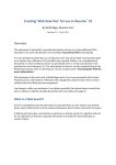
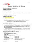
TriVibe
User Manual
Date: 19 January, 2015
Document Revision: 1.07
1
Telephone : +1 (832) 581-9908
E-mail
: [email protected]
Web
: www.machinesaver.com
© 2014 Machine Saver, Inc. and BiPOM Electronics, Inc. All rights reserved.
TriVibe User Manual. No part of this work may be reproduced in any manner without written
permission of Machine Saver, Inc. or BiPOM Electronics, Inc.
All trademarked names in this manual are the property of respective owners.
2
General Safety Summary
Review the following safety precautions to avoid injury and prevent damage to this product
or any products connected to it. To avoid potential hazards, use this product only as
specified. Only qualified personnel should perform installation and uninstallation
procedures.
CONNECT AND DISCONNECT PROPERLY
Do not connect or disconnect this product while it is connected to the live power source.
GROUND THE PRODUCT
The housing of this product should be connected to earth ground . Before attempting to turn on
the product ensure the housing
of this product is properly grounded.
OBSERVE ALL TERMINAL RATINGS
To avoid fire or shock hazard, observe all ratings and markings on the product. Consult the
product installation manual for further ratings
information before making connections to the product.
DO NOT OPERATE WITHOUT COVER
Do not operate this product with cover removed.
AVOID EXPOSURE TO CIRCUITRY
Do not touch exposed electrical connections and components when power is present.
DO NOT OPERATE WITH SUSPECT FAILURES
If you suspect there is damage to this product, have it inspected by qualified personnel.
3
Specifications
HV Power Consumption
LV Power Consumption
240V – 12mA
24V – 120mA
USB: Allows the user through the use of software to configure TriVibe
CAN Bus: TriVibe connects to a single VTB vibration sensor from Machine Saver.
4-20mA output: Serves for monitoring the vibration levels as an analog value using a PLC or any
other 4-20mA compatible device such as a chart recorder or data logger.
RS-485: Serves for connection to any device with an RS-485 interface and supporting MODBUS
RTU protocol.
LED’s: Red: Danger condition, Yellow : Alert condition, Green - power status.
RESET Button: Resets Alarm state.
DIP Switch: Connect terminating resistors for RS-485 and CAN
Relays: 10A/240VAC Single Pole Double Throw ( Common, Normally Open, Normally Closed
contacts )
Terminals: 20A/300V
VTB Sensor:
Frequency response: 0.4Hz – 5Khz or 0.4Hz – 800Hz
Environment: IP67, NEMA 4X or IP68 (submersible)
Hazardous Area: Class 1 Div 2 Grps A – D Hazardous Area
Certification (pending)
Temperature Range: -40°C to +105°C (-40°F to + 221°F)
Mounting bolt torque: 25 to 30 inch pounds (2.8 to 3.4 Newton meters).
Environmental
Operating Temperature Range -40 to 70°C (-40 to 158°F)
Humidity
up to 80%
Environmental Rating (Pending) UL94-5VA
Weight
0.35KG
Enclosure
ABS
4
Overview
TriVibe is an advanced vibration detection system and controller. It uses the latest in
microcontroller and vibration sensor technology to monitor and analyze a wide frequency and
amplitude range of vibrations and to decide if user-defined alarm levels are exceeded. Depending
on the vibration levels, one or two relays are activated to generate alert and danger alarms. The
relay outputs can be connected to beacons, sirens, Programmable Logic Controllers (PLC's) or
even control the machine causing the vibration to stop the machine if needed.
Using CAN Bus, TriVibe connects to a single VTB vibration sensor from Machine Saver. Each
TriVibe has its own VTB vibration sensor. VTB Vibration sensor is powered from TriVibe.
TriVibe itself is powered from 24VDC or 24VAC, with the option of 90 to 240VAC wide range AC
voltage input.
Alarm thresholds and other parameters of TriVibe can be programmed using a personal computer
over the USB connection or using a MODBUS RS485 Master (for example, PC, PLC, DCS) over
the optional RS485 connection.
TriVibe also has an optional 4-20mA output for monitoring the vibration levels as an analog value
using a PLC or any other 4-20mA compatible device such as a chart recorder or data logger.
5
Figure 1 shows all the connections of TriVibe.
LED’s
Relay Terminal
Connectors
90 to 240
VAC
Connector
RESET
Button
DIP Switches
USB
Connector
CAN Bus
Connector
RS-485
Connector
4-20mA
output
Connector
Low Voltage
Power
Connector
Figure 1
RS485 and 4-20mA features allow the vibration levels to be monitored also by an external device
to take further action when Alert and Danger conditions are detected.
TriVibe comes in a NEMA 4X enclosure with a transparent cover that allows viewing the LED's on
TriVibe to determine operating status. There are 3 LED's:
Red - Typically denotes a Danger condition
Yellow - Typically denotes an Alert condition
Green - Typically denotes power status
6
LED's may be solid or blinking. Also, one or more LED's can be turned on at the same time to
indicate different statuses.
Condition
Alert Level ( Low Alarm )
Alert Level ( High Alarm )
Danger Level ( High High Alarm )
Acknowledge of Alert Level
Acknowledge of Danger Level
Reset of any alarm
Power Problem
Fault
LED state
Blinking Yellow
Blinking Yellow
Blinking Red
Solid Yellow
Solid Red
Solid Green
Blinking Green
All LED’s blinking
Alarms can be acknowledged and reset using the red push button on TriVibe. Following an alarm,
press and release the red button to acknowledge the alarm. Following an acknowledgement, keep
the red button pressed for at least 5 seconds to reset the alarm. After the alarm is reset, the green
LED turns solid and other LED’s are turned off (unless there is yet another problem such as an
internal fault or a new alarm).
7
Board Layout
DIP
Switch
High
Voltage
Power
Connector
Relay 2
Connector
Relay 1
Connector
1 : Line
1 : NC
1 : NC
2 : Earth
2 : COM
2 : COM
3 : Earth
3 : NO
3 : NO
4 : Neutral
Green
LED
Yellow
LED
Red
LED
RESET
Button
USB
Connector
CAN
Connector
RS-485
Connector
4-20mA
Connector
1: VBUS
1: +24V
1:A
1 : + (Plus)
2 : USB_DM
2 : NC
2:B
2 : - (Minus)
3 : USB_DP
3 : CAN-H
3 : GND
4 : NC
4 : CAN-L
4 : Earth
5 : GND
5 : GND
6: Earth
6: Earth
Low
Voltage
Power
Connector
1 : Line 1
2 : Earth
3 : Line 2
Figure 2
8
VTB Sensor connection
VTB Sensor is connected to TriVibe through CAN Bus. VTB Sensor powers from TriVibe through
the CAN Bus power pins and uses CAN Bus signal pins to communicate with TriVibe. A 6-pin
removable terminal block OSTTS06315B on the TriVibe side connects to the VTB Sensor’s
shielded twisted pair cable. This connection is shown on the Figure 3.
SHIELD
GND (Black)
CAN-L (Green)
CAN-H (White)
CAN V+ (Red)
Figure 3
CAN Bus communication signals CAN-L and CAN-H belong to the same twisted pair. The other
pair has GND and CAN V+ for powering the VTB Sensor.
9
Programming the TriVibe
Alarm thresholds for the sensor can be programmed using the USB port on TriVibe. To
accomplish this, a Windows software called TriVibe Configurator is used.
Download TriVibe Configurator from Machine Saver web site:
http://machinesaver.com/wp-content/uploads/TriVibe/TriVibeSetup.exe
Install the TriVibe Configurator by following the on-screen instructions:
Click Next.
Click Next.
10
Click Install:
Click Finish.
If the checkbox is checked then TriVibe Configurator software will be started.
11
As next step you should connect the Windows PC to TriVibe’s USB port using the supplied USB
cable.
Figure 4
Windows will detect TriVibe as a USB device and will prompt to install the USB driver. The driver
already copied to Windows and only required to be automatically assigned to new device.
When you insert USB cable and power on TriVibe device you should see following window
Select last option No, not this time and click Next.
12
Select option Install the software automatically (Recommended) and click Next.
You will see following window while driver is copied to system folder:
13
When Hardware Installation warning window appears, click Continue Anyway to proceed with
copying the driver.
After driver installation, the following window appears:
Click Finish to close window and proceed with TriVibe Configurator.
14
TriVibe Configurator Software
Upon startup TriVibe Configurator will show the main screen:
The main screen has the following sections and options:
Connection
Under this section you can select the COM port that will be used to connect TriVibe device. Only
detected physical COM ports are shown.
If the checkbox Show only TriVibe compatible COM ports is checked, then only the TriVibe
virtual COM port will be shown.
Connect button allows connecting to TriVibe and reading current system information and
configuration.
TriVibe Rev. / VTB Sensor Rev.
These 2 text fields will show revisions of firmware installed on TriVibe and VTB Sensor.
15
Use 4-20mA Output
This checkbox controls 4-20mA output on TriVibe. If this checkbox is checked, then TriVibe sets
this output to the highest velocity value from 3 axes on the VTB Sensor.
Velocity is mapped as
0 ips = 4mA
1 ips = 20mA
2mA indicates an internal fault such as communications error or sensor out of calibration.
Configure Alarm Parameters
This button opens window to configure alarm thresholds. When software connects to TriVibe, the
current alarm thresholds are read from TriVibe and shown on this window.
This window has alarm thresholds for each of 3 axes, Temperature alarm thresholds and also
Trip Delay value.
For a time period of Trip Delay after the alarm condition first appears, the VTB sensor has to be
continuously in alarm condition for Trip Delay seconds for the corresponding relay to be activated
(tripped).
The default value of Trip Delay is 3 seconds and the range is from 1 second to 15 seconds. Any
other value in this field is not accepted. Startup Delay can be configured separately for each relay.
Each axis can be configured independently to alarm on Velocity or Acceleration by selecting
from the list. Individual fields allow configuring LOW, HIGH and HIGH HIGH thresholds as well as
Hysteresis.
16
The LOW alarm will be generated when signal (Velocity RMS or Acceleration RMS) drop below
set LOW level. If Hysteresis is set then signal should be drop below LOW – Hysteresis.
The HIGH alarms will be generated when signal (Velocity RMS or Acceleration RMS) rise above
set HIGH level. If Hysteresis is set then signal should be drop below HIGH – Hysteresis.
The HIGH HIGH alarms will be generated when signal (Velocity RMS or Acceleration RMS) rise
above set HIGH HIGH level. If Hysteresis is set then signal should be drop below HIGH HIGH –
Hysteresis.
Units selection can be English or Metric.
NOTE: TriVibe processes alarms only in English units so Metric values are automatically
converted to English before they are written to TriVibe.
Relay 1/ Relay 2
There are 2 relay settings sections. For each relay, Startup Delay and Alarm conditions can be
configured individually.
Following a time period of Startup Delay after power up, TriVibe will NOT activate the
corresponding relay. This is to ignore the vibration transients as large machines start up.
The default value of Startup Delay is 1 second and the range is from 1 second to 600 seconds.
Any other value in this field is not accepted.
To set alarm conditions, click the Add Alarm button:
Select alarms for relay and click Add button. All selected alarms will be added to Alarm
Conditions list on main screen and automatically written to TriVibe.
17
An internal fault is any problem inside TriVibe and not related to physical parameters being
measured. Internal faults include:
•
•
•
•
•
•
Bad VTB sensor cable
Bad VTB sensor
Out of calibration VTB sensor
Bad TriVibe
Communications problem between TriVibe and VTB Sensor
Power supply problems ( input voltage too low or too high )
Only temperature values between -40 Celsius and 105 Celsius are allowed as the values beyond
this range are outside the operating limits of VTB Sensor.
Only Low alarms (Alerts), High alarms (Alerts) and Internal Faults can be assigned to Relay 1.
Only High High alarms (Dangers) can be assigned to Relay 2.
18
Updating TriVibe Firmware
TriVibe Configurator also allows updating firmware on TriVibe device. To update firmware:
-
Copy TriVibe firmware HEX file to some location on PC.
Connect TriVibe Device to USB port of PC and power on.
Run TriVibe Configurator.
Select appropriate COM port in Connection section.
Click in main menu Tools à Update Firmware …
Update Firmware Settings window will be shown.
Click … button to the right of HEX File text box or just drag and drop HEX file on this window.
Click Start.
-
After Start is clicked Update Firmware window shows progress of firmware update.
19
-
When firmware is updated successfully, the following message appears:
-
Click OK, Update Firmware window disappears and TriVibe restarts.
20
Powering TriVibe
There are 2 options to power TriVibe: High voltage AC (mains) power or low voltage DC or AC
power.
To connect TriVibe to high voltage AC mains, prepare simple setup of OSTTS04515A removable
terminal block and assembled AC power cable with a plug. Pass the AC power cable through the
½” NPT fitting before connecting the removable terminal block. Connection scheme is shown on
Figure 5.
Neutral (Blue)
Earth (Green)
Live (Brown)
Figure 5
21
To power TriVibe from a low voltage source, use a 10 to 30V DC power source, with current
capability 1A or higher. Use OSTTS03315B removable terminal block. Either pin #1 or pin #3 can
be used for PLUS or MINUS; the polarity does not matter. Connect pin #2 to power line Earth. DC
connection scheme is shown on Figure 6.
10-30V (+)
10-30V (-)
Low Voltage
DC Operation
Earth
Low Voltage
AC Operation
110VAC/24VAC
transformer
Earth
Figure 6
22
RS-485
TriVibe can be connected to any device with an RS-485 interface and supporting MODBUS RTU
protocol. The device can be a Personal Computer with a USB to RS-485 converter (Figure 7),
Programmable Logic Controller (Figure 8), Distributed Control System (Figure 9), or any other
MODBUS RTU Master device.
TriVibe
Personal
Computer
USB to
RS-485
Converter
RS-485
Connector
Figure 7
23
PLC
Programmable
Logic Controller
TriVibe
RS485
Connector
Figure 8
DCS
Distributed Control
System
TriVibe
RS-485
Connector
Figure 9
24
Terminating resistors
A terminating resistor is simply a resistor placed at the extreme end or ends of a RS-485 cable
(Figure 10). The value of the terminating resistor is ideally the same value as the characteristic
impedance of the cable.
Figure 10
To setup terminating resistor for RS-485, turn SW2.3 ON, as it shown on Figure 11.
Figure 11
Terminating scheme for CAN bus is shown on the Figure 12. To setup terminating resistors for
CAN bus, turn SW2.1 and SW2.2 ON, as it shown on Figure 13.
Figure 12
Figure 13
25
4-20mA Output
TriVibe can be connected to any device, accepting 4-20mA current loop, such as a PLC
(Programmable Logic Controller).
4-20mA
Connector
Figure 14
26
Appendix A: Balance of Plant – Practical Vibration Monitoring Guidelines
for TriVibe
Machine Saver, Inc. is pleased to provide a new technology that can be coupled to a best practice
procedure which can be used for all your balance of plant vibration monitoring.
In the past, a portable vibration meter was used to determine the highest vibration plane on a
machine. Then the permanent vibration sensors were placed on the vertical or horizontal axis that
was most sensitive to a machine’s vibrations.
VTB-Sensor, 3 – Axis Digital Transmitter takes the guess work out of the mounting location and
can simultaneously detect in three measurement planes (X,Y, and Z) and in two vibration
measurands- acceleration and velocity. The embedded temperature sensor has a service range
of -40°F to 221°F (-40°C to 105°C). By integrating 3-axis vibration detection and temperature into
one digital transmitter, one transmitter can take the place of seven sensors. Note that the TriVibe
can only support one (1) VTB-Sensor.
For most balance of plant applications, mount one (1) VTB-Sensor on machine driver (inboard)
and one (1) VTB-Sensor on the driven machine (inboard) per the following guidelines:
1) Decide to install what is required instead of installing what is simple or convenient. As a
protection device, a mechanical switch is unreliable and has no useful signal outputs, no
trending capabilities, no analysis capabilities for condition monitoring, and no advance
warnings for a deteriorating machine.
Some companies have a machine condition
monitoring system and they use the mechanical switch for machine protection in case there is
a brown out period or a power outage. VTB-Net can reliably shutdown your machine asset by
utilizing a separately priced external relay board. To insure continuous vibration monitoring
and protection, simply utilize an Uninterruptible Power Supply (UPS) set to a nominal +24
VDC to power the TriVibe and interconnected VTB-Sensor.
2) Obtain technical expertise from Machine Savers, Inc., with applications involving the use of
band pass filters for the diagnosis of machine vibration levels; or, the use of vibration devices
in a hazardous locations or corrosive environments, e.g., sour gas, salt-spray, high or low pH
levels.
3) Verify that the machine rotating shafts are supported by rolling element bearings. VTB-Sensor
is a digital sensor that was designed to detect and monitor low frequency vibrations, e.g.,
imbalance, misalignment, high frequency roller bearing condition, and temperature. Mount the
VTB-Sensor in the radial position at or around the roller bearing cap. Do not mount the digital
transmitter on a flimsy bracket, or the sheet metal part of the machine.
4) Vertical pumps and air compressors may have a mix of sleeve bearings and roller bearings.
Simply mount the VTB-Sensor as close as possible to the roller bearings.
5) For small horizontal pumps or compressors with sleeve bearings, mount one (1) VTB-Sensor
per machine in the radial position perpendicular to the rotating shaft.
Since the vibrations
are attenuated by the sleeve bearing, trend the overall vibration levels continuously and
accordingly lower your set point trip levels. Remember for each machine you are trending
one temperature level and nine vibration levels. Therefore, overtime, you may have a
measurement plane that a very low vibration level, but the other measurement planes will
indicate changes in vibration levels due to machine’s low frequency vibration levels, e.g.,
imbalance or misalignment.
27
6) Review the machine’s maintenance records. Mount the VTB-Sensor as close as possible to
source of vibration. Based on the records, this area will have the most wear and is most likely
to have problems.
7) On less expensive motors, blowers, pumps, fans, compressors, consider a budgetary
approach and mount at least one VTB-Sensor per set. Place the VTB-Sensor where it will
monitor the most- on the inboard section of the driven machine, e.g., pump, compressor, or
fan. This area will have the most wear, and is most likely to have problems.
8) Understand what trending the overall vibration levels means. Overall vibration is the total
vibration energy measured within a wide frequency range. Overtime, a higher than normal
overall vibration level indicates that some force is causing the machine to vibrate more. As
you increase the speed of the machine that vibration energy becomes more destructive. The
enhanced overall vibration levels provided by VTB-Sensor will indicate continuously what your
overall vibration levels are and this provides time for operators to create a standard baseline
vibration level for each machine asset. Once the baseline vibration levels are reached, you
can plan and schedule an inspection of the machine components and the roller bearings.
Suggested Vibration Trip Levels
You can monitor the vibration levels in three simultaneous planes (X,Y, and Z) and in three
vibration measurands, but, the velocity measurand is best for speeds of 600 RPM (10 Hz) or
greater. This is because the velocity (ips) measurement is constant over a wide range of speeds
and frequencies. For example, a fan operating at 900 rpm (15 Hz) would be protected for
unbalance at the operating speed; and it would also be protected for a bent shaft or shaft
misalignment, which may occur at the second harmonic, 1800 rpm (30 Hz).
For machine protection, the typical vibration trip levels are shown below for different types of
balance of plant machinery. Note that these trip levels are suggested starting points, but, the
recommendations provided by the equipment manufacture should be followed. Preliminary
references for suggested vibration limits are the Vibration Institute, the Cooling Technology
Institute (cooling towers), the Hydraulic Institute (pumps), ISO-2372, and ISO-10816-3.
Overall Vibration Levels – X, Y, and Z and Acceleration, and Velocity
The easiest way to obtain the base line vibration for your machine is to simply measure the
vibration levels over a wide frequency range. The VTB-Sensor must be mounted on the bearing
housing or as close as possible to the roller bearings.
Analysis of trended vibration levels combined with experience and familiarity with the machine is
essential to monitor the status of your machine. In addition to vibration measurements,
temperature is an important parameter for providing information on bearing stress and machine
operating conditions. Analysis of vibration and temperature together provides condition monitoring
where the condition of the machine is monitored for early signs of deterioration. The table below
provides some common machine vibration and temperature faults.
28
Balance of Plant – Common Machine Vibration and Temperature Faults
Machine
Component/Faul
t
Belt Drive Pulley
System/Worn or
Improper Belt tensions
Belt Drive Pulley
System/Misaligned
Pulley/Eccentric
Pulley/Belt Resonance
Belt Drive Pulley
System/
Eccentric Pulley/Belt
Resonance
Measureme
nt Plane
Vibration
Measurand
1X,2X,3X,4X RPM of
Belt
Radial
Velocity, ips/sec, pk
1X,2X RPM of Belt
Axial
Frequency Order
Velocity, ips/sec, pk
1X RPM of Belt
Radial
Velocity, ips/sec, pk
Comments
Belt frequencies are below the
RPM of either the motor or the
driven machine. When they
are worn, loose or
mismatched, they can cause
dominant vibration peaks at
2X, 3X, and 4X RPM of Belt.
Small amplitudes of axial
vibration can occur.
Excessive driver pulley and
driven sprocket misalignment
or extreme sheave wear may
appear as imbalance. Three
types of pulley misalignment:
offset, angular, and twisted.
Eccentric Pulleys: The
geometric center does not
coincide with the rotating
center of the pulley and the
vibration may be higher in the
directions of the belts.
Belt resonance may coincide
with either the driver pulley or
driven sprocket RPM.
Motor/Imbalance
1X, 2X Motor RPM
Radial
Velocity, ips/sec, pk
Motor/Bent Shaft
1X, 2X Motor RPM
Axial
Velocity, ips/sec, pk
Motor/Mechanical
Looseness
1/2X,1/3X,1/4X,1X,2X,
Motor RPM
Radial (Vertical)
Velocity, ips/sec, pk
Motor/Rotor Bar and
Stator Defects
1X,2X,3XMotor RPM
2X Line Frequency
Radial
Velocity, ips/sec, pk
29
Small amplitudes of axial
vibration can occur.
Imbalance can be intensified
by mechanical resonance.
1X Motor RPM vibration can
also be caused by Soft Foot.
Bent shaft can cause roller
bearings misalignment.
There may be some vibration
levels on the horizontal plane,
but, the amplitudes will be
highest near the mechanical
fault. Excessive coupling
wear can lead to mechanical
looseness.
Rotor Bar Passing Frequency
(FRBPF) = Motor RPM X No. of
Rotor Bars. Broken rotor bars
are common faults that cause
electrical imbalance. Small
amplitudes of axial vibration
can occur.
Motor/Shaft/Coupling
Misalignment
Motor/Fan/Resonance
Centrifugal Pump
Rolling Bearing
Defects with Visible
Damage to the
Bearings
1X,2X,3X
4X,5X,6X, Low Level
Harmonics
Less Than, Equal to, or
Greater Than Motor/Fan
RPM
Axial and/or
Radial
Velocity, ips/sec, pk
Radial, Axial
Velocity, ips/sec, pk
Number of Impeller
Vanes X RPM
Radial
Velocity, ips/sec, pk
1X to 10X
Radial
Velocity, ips/sec, pk
Shaft/Coupling Misalignment
may involve both Angular
(Axial) and Parallel Offset
(Radial) Misalignment.
Misalignment can occur under
the following conditions: 1.
Machine alignment and
installations errors; 2. worn
roller bearings; 3. settling of
bases, foundations, and tower
structure; 4. shift of relative
position of machines after
installation.
Resonance appears when a
source frequency coincides
with the natural frequency of
the support structure, base
foundation, piping, or
mechanical component, e.g.,
rotor, gearbox, or belt driven
systems. Resonance can be
confirmed by verifying that a
small change in speed causes
the 1X Motor RPM or Blade
Pass Frequency vibration
levels to change greatly.
For pumps- cavitation can be
caused by improper supply of
process fluid. Mount the VTBSensor near the pump inlet
(suction) area to monitor for
cavitation. An impeller vane
filled with foreign material or
impeller erosion can lead to
machine imbalance or
misalignment.
The vibration frequencies
begin to manifest themselves
in the 5 KHz to 15 KHz range.
As the roller bearing
wear increases and
approaches failure, there will
be an increase in overall
vibration levels in the 500 Hz
to 2500 Hz range.
For bearing defects within 1X
to 10X Machine RPM,
schedule a machine repair
as soon as possible and
inspect the roller bearings.
If required, replace the roller
bearings and find the
fault(s) causing the bearing
defects, e.g., imbalance,
misalignment, improper
bearing loads, excessive
bearing temperature,
contaminated lubrication, or,
insufficient bearing lubrication.
30
Gearbox/Mechanical
Looseness
Gearbox/Worn or
Broken Gear Teeth
1X,2X Fan RPM
GMF X 3.25
Radial (Vertical)
Radial
Velocity, ips/sec, pk
Velocity, ips/sec, pk
AC Motor Windings
and Roller Bearings
Gearbox Roller
Bearings
Radial
Axial
(Overheating)
Velocity, ips/sec, pk
There may be some vibration
levels on the horizontal plane,
but, the amplitudes will be
highest near the mechanical
fault.
Gear Mesh Frequency (GMF)
= [No. of TeethGearX
RPMGear]or [No. of TeethPinion X
RPMPinion] Shaft misalignment
can cause high loads on the
input gear, which causes
misaligned gears and can lead
to worn or broken gear teeth.
VTB-Sensor can detect and
monitor for excessive machine
heat that causes rapid
deterioration of motor winding
insulation and roller bearing
damage that can lead to AC
motor failure.
Overheating in the AC motor
bearings is generally lubricantrelated. Normal motor bearing
operating temperatures range
from 140°F (60°C) to 160°F
(71°C). Roller bearings in
gear drives normally operate
at 160° (71°C)-180°F (82°C).
Overheating in motors and
gearboxes can be caused by
increased bearing loads due
to machine imbalance or
misalignment.
Contamination of the roller
bearings lubricant by solid
particles, water, and other
fluids can reduce the life of the
bearings. Improper lubrication
generally causes overheating
or excessive wear in the roller
bearings. These conditions
can result from insufficient or
excessive lubrication,
improper lubricants, e.g.,
viscosity is the load bearing
component of the lubricant.
Too thin, then the bearings
cannot properly carry the load;
and too thick, then the amount
of friction will generate heat.
Packing the space around the
roller bearings with grease can
also cause excessive heat.
Avoid the use high pressure
grease guns since they may
rupture the bearing seals.
31
Appendix B: MODBUS registers of VTB sensor
Register
Name
40001
SYSTEM INFO
(read only)
40002
SYSTEM CONTROL
(read, write)
40003
SYSTEM STATUS
(read only)
40004
SYSTEM STATE1
(read only)
40005
SYSTEM STATE2
(read only)
40006
40007
40008
MINUTES SINCE
POWER ON
(read only)
HOURS SINCE
POWER ON
(read only)
DAYS SINCE
POWER ON
(read only)
40009
ALARM RELAY1
STATE
(read only)
40010
ALARM RELAY2
STATE
(read only)
40011
ALARM STATE
(read only)
Description
Firmware ID and REVISION
Control register to drive the most critical system
commands:
0 - idle
1 - reset
22222 – update MODBUS STATUS register
45555 - unlock configuration registers as read/write
(non-public)
45556 - save configuration registers to non-volatile
memory (non-public)
Status of the last executed system command
0-idle
1-done
2-in progress
3-error
States of main system components
Bit0-power output (1-error,0-OK)
Bit1-power input (1-error,0-OK)
Bit2-power 5V (1-error,0-OK)
Bit3-power 3.3V (1-error,0-OK)
States of main system components
Bit0-power (1-error,0-OK)
Bit1-sensor (1-error,0-OK)
Bit2-non-volatile memory (1-error,0-OK)
Minutes since power on
Hours since power on
Hours since power on
States of the relay1 alarms
Bit0-LOW alarm
Bit1-HIGH alarm
Bit2-HIGH_HIGH alarm
Bit3-internal alarm
States of the relay2 alarms
Bit0-LOW alarm
Bit1-HIGH alarm
Bit2-HIGH_HIGH alarm
Bit3-internal alarm
States of detected alarms
Bit0-LOW alarm
Bit1-HIGH alarm
Bit2-HIGH_HIGH alarm
Bit3-internal alarm
32
40012
40013
40014
40015
40016
40017
40018
ALARM ACK STATE
(read only)
MASTER TIMEOUT
(read, write)
LAST SYSTEM
ERROR
(read only)
SYSTEM MODE
(read only)
SYSTEM ERROR
(read only)
ECU
(read only)
RTU
(read only)
States of ACK’ed alarms
Bit0-LOW alarm
Bit1-HIGH alarm
Bit2-HIGH_HIGH alarm
Bit3-internal alarm
Master timeout in seconds.
When the value is not ZERO the MODBUS SLAVE
mode is activated. The register decreases every second.
When ZERO value is reached the MODBUS MASTER
mode is activated.
Code of the last error
Not used
Code of the system executed command
ECU address
MODBUS RTU
Control register to drive peripherals remotely in
MODBUS SLAVE mode.
40019
CONTROL
(read, write)
Bit0-green LED (1-ON,0-OFF)
Bit1-yellow LED (1-ON,0-OFF)
Bit2-7-reserved
Bit8-relay 1 (1-ON,0-OFF)
Bit9-relay 2 (1-ON,0-OFF)
Bit10-14-reserved
Bit15-reset button(1-PRESSED,0-RELEASED)
Register to obtain info about current states of
peripherals remotely in MODBUS SLAVE mode.
To update the content of the register it is necessary to
execute a special command writing 22222 (update
MODBUS STATUS register) to SYSTEM CONTROL
register.
40020
STATUS
(read only)
40021
DAC RAW VALUE
40022
OUTPUT CURRENT
FEEDBACK
CURRENT
REGF VOLTAGE
Output current in uA
RESERVED
Reserved registers
40023
40024
4002540032
Bit0-green LED (1-ON,0-OFF)
Bit1-yellow LED (1-ON,0-OFF)
Bit2-7-reserved
Bit8-relay 1 (1-ON,0-OFF)
Bit9-relay 2 (1-ON,0-OFF)
Bit10-14-reserved
Bit15-reset button(1-PRESSED,0-RELEASED)
The last raw value (0-4095) was written to 12-bit DAC
Feedback current in uA
Reference voltage of a current loop chip in mV
33
40033
40034
40035
40036
40037
40038
30039
40040
40041
40042
HUIDH
(read only)
LUIDH
(read only)
HUIDMH
(read only)
LUIDMH
(read only)
HUIDML
(read only)
LUIDML
(read only)
HUIDL
(read only)
LUIDL
(read only)
STARTUP DELAY1
(non-volatile)
TRIP DELAY1
(non-volatile)
High 16 bits of UIDH register of 128-bit unique
identification code
Low 16 bits of UIDH register of 128-bit unique
identification code
High 16 bits of HUIDMH register of 128-bit unique
identification code
Low 16 bits of UIDMH register of 128-bit unique
identification code
High 16 bits of UIDML register of 128-bit unique
identification code
Low 16 bits of UIDML register of 128-bit unique
identification code
High 16 bits of UIDL register of 128-bit unique
identification code
Low 16 bits of UIDL register of 128-bit unique
identification code
Power ON Delay before the relay1 is activated
Not used
High 16-bits of alarm configuration word of relay 1
40043
HIGH CONFIG1
(non-volatile)
Bit0-axis2 high-high velocity
Bit1-axis3 high-high velocity
Bit2-low temperature
Bit3-high temperature
Bit4-high-hightemperature
Bit5-internal fault
Bit6-power fault
Low 16-bits of alarm configuration word of relay 1
40044
LOW CONFIG1
(non-volatile)
40045
STARTUP DELAY2
(non-volatile)
40046
TRIP DELAY2
(non-volatile)
Bit0-axis1 low acceleration
Bit1-axis2 low acceleration
Bit2-axis3 low acceleration
Bit3-axis1 high acceleration
Bit4-axis2 high acceleration
Bit5-axis3 high acceleration
Bit6-axis1 high-high acceleration
Bit7-axis2 high-high acceleration
Bit8-axis3 high-high acceleration
Bit9-axis1 low velocity
Bit10-axis2 low velocity
Bit11-axis3 low velocity
Bit12-axis1 high velocity
Bit13-axis1 high velocity
Bit14-axis1 high velocity
Bit15-axis1 high-high velocity
Power ON Delay before the relay2 is activated
Not used
34
High 16-bits of alarm configuration word of relay 2
40047
HIGH CONFIG2
(non-volatile)
Bit0-axis2 high-high velocity
Bit1-axis3 high-high velocity
Bit2-low temperature
Bit3-high temperature
Bit4-high-hightemperature
Bit5-internal fault
Bit6-power fault
Low 16-bits of alarm configuration word of relay 2
40048
LOW CONFIG1
(non-volatile)
40049
SENSOR/SWITCH
RTUs
(non-volatile)
40050
MODE CONFIG
(non-volatile)
4005140054
RESERVED
(non-volatile)
Bit0-axis1 low acceleration
Bit1-axis2 low acceleration
Bit2-axis3 low acceleration
Bit3-axis1 high acceleration
Bit4-axis2 high acceleration
Bit5-axis3 high acceleration
Bit6-axis1 high-high acceleration
Bit7-axis2 high-high acceleration
Bit8-axis3 high-high acceleration
Bit9-axis1 low velocity
Bit10-axis2 low velocity
Bit11-axis3 low velocity
Bit12-axis1 high velocity
Bit13-axis1 high velocity
Bit14-axis1 high velocity
Bit15-axis1 high-high velocity
High 8-bit field represents a sensor RTU.
low 8-bit field represents a switch RTU.
Mode configuration register
Bit0-current loop (1-enabled, 0-disabled)
Reserved non-volatile registers
35