1
Safety Function: SensaGuard Non-contact Interlock Switch
17
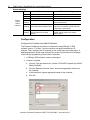
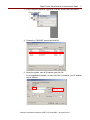
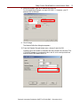
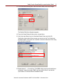
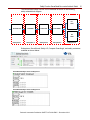
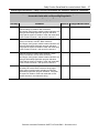
6. Click Output Configuration and configure the module as shown.
Typically, contactor coils will not react to the pulse testing of the output wires.
If using a contactor that does react to the pulse test, then disable the pulse
testing. This should not affect the overall safety rating if redundancy and
monitoring are being utilized.
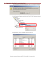
7. Click OK.
Programming
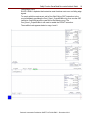
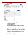
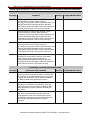
The Dual Channel Input Stop (DCS) instruction monitors dual-input safety devices
whose main function is to stop a machine safely, for example, an E-stop, light
curtain, or safety gate. In this example, the DCS instruction is being used to monitor
a SensaGuard switch and an E-stop button.
The DCS instruction monitors dual-input channels for consistency (Equivalent-Active
High) and detects and traps faults when the inconsistency is detected for longer than
the configured Discrepancy Time (ms).
The automatic restart type allows the DCS output (O1) to reset automatically after a
demand. The manual action typically required for safety is provided in rung 1 to reset
the safety output enable.
Input Status typically represents the channel status of the two input channels. In this
example, the Combined Input Status bit goes low (0) if any of the eight input
channels has a fault.
In this example, the DCS reset acts as a fault reset. Even when configured for
automatic restart, a reset is required to recover from a fault.
The output (01) of the DCS instruction is used as a safety interlock in the seal-in rung
to drive the output enable tag. If the DCS output drops out, so does the output
enable, and it remains off until you manually reset it.
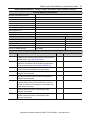
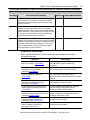
The Configurable Redundant Output (CROUT) instruction controls and monitors
redundant outputs. Essentially, this instruction verifies that feedback follows the
safety outputs appropriately. For the negative feedback used in this example, if the
outputs are high (1), the Feedback is low (0) and vice versa. In this example, the
feedback has 500 ms to change to the proper state. Because only a single feedback
circuit is being used, the feedback tag is used for both Feedback 1 and 2.
Rockwell Automation Publication SAFETY-AT108A-EN-P – December 2013