1
UM0424
User manual
STM32 USB-FS-Device development kit
Introduction
The STM32 USB-FS-Device development kit is a complete firmware and software package
including examples and demos for all USB transfer types (control, interrupt, bulk and
isochronous).
The aim of the STM32 USB-FS-Device development kit is to use the STM32 USB-FSDevice library with at least one firmware demo per USB transfer type.
This document presents a description of all the components of the STM32 USB-FS-Device
development kit, including:
■
STM32 USB-FS-Device library: All processes related to default endpoint and standard
requests
■
Device firmware upgrade (DFU) demo: Control transfer
■
Joystick mouse demo: Interrupt transfer
■
Custom HID demo: Interrupt transfer
■
Mass storage demo: Bulk transfer
■
Virtual COM port: Interrupt and bulk transfer
■
CDC LoopBack demo: Interrupt and bulk transfer
■
Composite Example: Interrupt and bulk transfer
■
USB voice speaker demo (USB speaker): Isochronous transfer
Table 1.
Applicable products
Type
Part numbers or product categories
STM32F102xx and STM32F103xx series
Microcontrollers
STM32 L1 Ultra Low Power
STM32 F3 Series
Note:
Starting from this release, STM32F105/F107 are no longer supported. These devices are
supported by the STM32 USB OTG Host and Device Library. For more details, please refer
to user manual UM1021.
December 2012
Doc ID 13465 Rev 12
1/85
www.st.com
Contents
UM0424
Contents
1
Related documents . . . . . . . . . . . . . . . . . . . . . . . . . . . . . . . . . . . . . . . . . . 8
2
STM32 microcontroller family overview . . . . . . . . . . . . . . . . . . . . . . . . . 9
3
STM32 USB-FS-Device firmware library . . . . . . . . . . . . . . . . . . . . . . . . 10
3.1
USB application hierarchy . . . . . . . . . . . . . . . . . . . . . . . . . . . . . . . . . . . . 10
3.2
USB-FS_Device peripheral interface . . . . . . . . . . . . . . . . . . . . . . . . . . . . 12
3.3
3.4
3.5
4
2/85
3.2.1
usb_reg(.h, .c) . . . . . . . . . . . . . . . . . . . . . . . . . . . . . . . . . . . . . . . . . . . . 12
3.2.2
usb_int (.h , .c) . . . . . . . . . . . . . . . . . . . . . . . . . . . . . . . . . . . . . . . . . . . . 17
3.2.3
usb_mem (.h , .c) . . . . . . . . . . . . . . . . . . . . . . . . . . . . . . . . . . . . . . . . . . 17
USB-FS-Device_Driver medium layer . . . . . . . . . . . . . . . . . . . . . . . . . . . 17
3.3.1
usb_init(.h,.c) . . . . . . . . . . . . . . . . . . . . . . . . . . . . . . . . . . . . . . . . . . . . . 17
3.3.2
usb_core (.h , .c) . . . . . . . . . . . . . . . . . . . . . . . . . . . . . . . . . . . . . . . . . . 17
3.3.3
usb_sil(.h, .c) . . . . . . . . . . . . . . . . . . . . . . . . . . . . . . . . . . . . . . . . . . . . . 21
3.3.4
usb_type.h / usb_def.h . . . . . . . . . . . . . . . . . . . . . . . . . . . . . . . . . . . . . 21
3.3.5
platform_config.h . . . . . . . . . . . . . . . . . . . . . . . . . . . . . . . . . . . . . . . . . . 21
Application interface . . . . . . . . . . . . . . . . . . . . . . . . . . . . . . . . . . . . . . . . . 21
3.4.1
usb_conf(.h) . . . . . . . . . . . . . . . . . . . . . . . . . . . . . . . . . . . . . . . . . . . . . . 22
3.4.2
usb_desc (.h, .c) . . . . . . . . . . . . . . . . . . . . . . . . . . . . . . . . . . . . . . . . . . 22
3.4.3
usb_prop (.h , .c) . . . . . . . . . . . . . . . . . . . . . . . . . . . . . . . . . . . . . . . . . . 23
3.4.4
usb_endp (.c) . . . . . . . . . . . . . . . . . . . . . . . . . . . . . . . . . . . . . . . . . . . . . 24
3.4.5
usb_istr(.c) . . . . . . . . . . . . . . . . . . . . . . . . . . . . . . . . . . . . . . . . . . . . . . . 25
3.4.6
usb_pwr (.h , .c) . . . . . . . . . . . . . . . . . . . . . . . . . . . . . . . . . . . . . . . . . . . 25
Implementing a USB-FS_Device application using the STM32 USB-FSDevice library 25
3.5.1
Implementing a no-data class-specific request . . . . . . . . . . . . . . . . . . . 25
3.5.2
How to implement a data class-specific request . . . . . . . . . . . . . . . . . . 25
3.5.3
How to manage data transfers in non-control endpoint . . . . . . . . . . . . . 26
Joystick mouse demo . . . . . . . . . . . . . . . . . . . . . . . . . . . . . . . . . . . . . . . 27
4.1
General description . . . . . . . . . . . . . . . . . . . . . . . . . . . . . . . . . . . . . . . . . 27
4.2
STM32 low-power management in suspend mode . . . . . . . . . . . . . . . . . 27
4.3
Remote wakeup implementation . . . . . . . . . . . . . . . . . . . . . . . . . . . . . . . 28
Doc ID 13465 Rev 12
UM0424
5
6
Contents
Custom HID demo . . . . . . . . . . . . . . . . . . . . . . . . . . . . . . . . . . . . . . . . . . 30
5.1
General description . . . . . . . . . . . . . . . . . . . . . . . . . . . . . . . . . . . . . . . . . 30
5.2
Descriptor topology . . . . . . . . . . . . . . . . . . . . . . . . . . . . . . . . . . . . . . . . . 30
5.3
Custom HID implementation . . . . . . . . . . . . . . . . . . . . . . . . . . . . . . . . . . 31
5.3.2
Push-button state report . . . . . . . . . . . . . . . . . . . . . . . . . . . . . . . . . . . . 32
5.3.3
ADC-converted data transfer . . . . . . . . . . . . . . . . . . . . . . . . . . . . . . . . . 32
6.1
General description . . . . . . . . . . . . . . . . . . . . . . . . . . . . . . . . . . . . . . . . . 33
6.2
Mass storage demo overview . . . . . . . . . . . . . . . . . . . . . . . . . . . . . . . . . . 33
6.3
Mass storage protocol . . . . . . . . . . . . . . . . . . . . . . . . . . . . . . . . . . . . . . . 34
6.5
8
LED control . . . . . . . . . . . . . . . . . . . . . . . . . . . . . . . . . . . . . . . . . . . . . . 31
Mass storage demo . . . . . . . . . . . . . . . . . . . . . . . . . . . . . . . . . . . . . . . . . 33
6.4
7
5.3.1
6.3.1
Bulk-only transfer (BOT) . . . . . . . . . . . . . . . . . . . . . . . . . . . . . . . . . . . . 34
6.3.2
Small computer system interface (SCSI) . . . . . . . . . . . . . . . . . . . . . . . . 38
Mass storage demo implementations . . . . . . . . . . . . . . . . . . . . . . . . . . . . 39
6.4.1
Hardware configuration interface . . . . . . . . . . . . . . . . . . . . . . . . . . . . . . 39
6.4.2
Endpoint configurations and data management . . . . . . . . . . . . . . . . . . 40
6.4.3
Class-specific requests . . . . . . . . . . . . . . . . . . . . . . . . . . . . . . . . . . . . . 41
6.4.4
Standard request requirements . . . . . . . . . . . . . . . . . . . . . . . . . . . . . . . 42
6.4.5
BOT state machine . . . . . . . . . . . . . . . . . . . . . . . . . . . . . . . . . . . . . . . . 42
6.4.6
SCSI protocol implementation . . . . . . . . . . . . . . . . . . . . . . . . . . . . . . . . 43
6.4.7
Memory management . . . . . . . . . . . . . . . . . . . . . . . . . . . . . . . . . . . . . . 44
6.4.8
Medium access management . . . . . . . . . . . . . . . . . . . . . . . . . . . . . . . . 44
How to customize the mass storage demo . . . . . . . . . . . . . . . . . . . . . . . 46
Virtual COM port demo . . . . . . . . . . . . . . . . . . . . . . . . . . . . . . . . . . . . . . 49
7.1
General description . . . . . . . . . . . . . . . . . . . . . . . . . . . . . . . . . . . . . . . . . 49
7.2
Virtual COM port demo proposal . . . . . . . . . . . . . . . . . . . . . . . . . . . . . . . 49
7.3
Software driver installation . . . . . . . . . . . . . . . . . . . . . . . . . . . . . . . . . . . . 50
7.4
Implementation . . . . . . . . . . . . . . . . . . . . . . . . . . . . . . . . . . . . . . . . . . . . . 51
7.4.1
Hardware implementation . . . . . . . . . . . . . . . . . . . . . . . . . . . . . . . . . . . 51
7.4.2
Firmware implementation . . . . . . . . . . . . . . . . . . . . . . . . . . . . . . . . . . . 51
VirtualComport_Loopback . . . . . . . . . . . . . . . . . . . . . . . . . . . . . . . . . . . 53
8.1
General description . . . . . . . . . . . . . . . . . . . . . . . . . . . . . . . . . . . . . . . . . 53
8.2
Demo overview . . . . . . . . . . . . . . . . . . . . . . . . . . . . . . . . . . . . . . . . . . . . . 53
Doc ID 13465 Rev 12
3/85
Contents
UM0424
8.3
8.4
9
10
8.3.1
Sending data from device to host . . . . . . . . . . . . . . . . . . . . . . . . . . . . . 54
8.3.2
Receiving data from host to device . . . . . . . . . . . . . . . . . . . . . . . . . . . . 54
Running the demo . . . . . . . . . . . . . . . . . . . . . . . . . . . . . . . . . . . . . . . . . . 54
USB voice speaker demo . . . . . . . . . . . . . . . . . . . . . . . . . . . . . . . . . . . . 55
9.1
General description . . . . . . . . . . . . . . . . . . . . . . . . . . . . . . . . . . . . . . . . . 55
9.2
Isochronous transfer overview . . . . . . . . . . . . . . . . . . . . . . . . . . . . . . . . . 55
9.3
Audio device class overview . . . . . . . . . . . . . . . . . . . . . . . . . . . . . . . . . . 56
9.4
STM32 USB audio speaker demo . . . . . . . . . . . . . . . . . . . . . . . . . . . . . . 57
9.4.1
General characteristics . . . . . . . . . . . . . . . . . . . . . . . . . . . . . . . . . . . . . 58
9.4.2
Implementation . . . . . . . . . . . . . . . . . . . . . . . . . . . . . . . . . . . . . . . . . . . 59
Device firmware upgrade . . . . . . . . . . . . . . . . . . . . . . . . . . . . . . . . . . . . 67
10.1
General description . . . . . . . . . . . . . . . . . . . . . . . . . . . . . . . . . . . . . . . . . 67
10.2
DFU extension protocol . . . . . . . . . . . . . . . . . . . . . . . . . . . . . . . . . . . . . . 68
10.3
10.2.1
Introduction . . . . . . . . . . . . . . . . . . . . . . . . . . . . . . . . . . . . . . . . . . . . . . 68
10.2.2
Phases . . . . . . . . . . . . . . . . . . . . . . . . . . . . . . . . . . . . . . . . . . . . . . . . . . 68
10.2.3
Requests . . . . . . . . . . . . . . . . . . . . . . . . . . . . . . . . . . . . . . . . . . . . . . . . 69
DFU mode selection . . . . . . . . . . . . . . . . . . . . . . . . . . . . . . . . . . . . . . . . . 69
10.3.1
Run-time descriptor set . . . . . . . . . . . . . . . . . . . . . . . . . . . . . . . . . . . . . 69
10.3.2
DFU mode descriptor set . . . . . . . . . . . . . . . . . . . . . . . . . . . . . . . . . . . . 70
10.4
Reconfiguration phase . . . . . . . . . . . . . . . . . . . . . . . . . . . . . . . . . . . . . . . 74
10.5
Transfer phase . . . . . . . . . . . . . . . . . . . . . . . . . . . . . . . . . . . . . . . . . . . . . 74
10.6
4/85
Transferring data . . . . . . . . . . . . . . . . . . . . . . . . . . . . . . . . . . . . . . . . . . . 54
10.5.1
Requests . . . . . . . . . . . . . . . . . . . . . . . . . . . . . . . . . . . . . . . . . . . . . . . . 74
10.5.2
Special command/protocol descriptions . . . . . . . . . . . . . . . . . . . . . . . . 75
10.5.3
DFU state diagram . . . . . . . . . . . . . . . . . . . . . . . . . . . . . . . . . . . . . . . . . 76
10.5.4
Downloading and uploading . . . . . . . . . . . . . . . . . . . . . . . . . . . . . . . . . 77
10.5.5
Manifestation phase . . . . . . . . . . . . . . . . . . . . . . . . . . . . . . . . . . . . . . . . 77
STM32 DFU implementation . . . . . . . . . . . . . . . . . . . . . . . . . . . . . . . . . . 78
10.6.1
Supported memories . . . . . . . . . . . . . . . . . . . . . . . . . . . . . . . . . . . . . . . 78
10.6.2
DFU mode entry mechanism . . . . . . . . . . . . . . . . . . . . . . . . . . . . . . . . . 78
10.6.3
DFU firmware architecture . . . . . . . . . . . . . . . . . . . . . . . . . . . . . . . . . . . 78
10.6.4
Available DFU image for the STM32 . . . . . . . . . . . . . . . . . . . . . . . . . . . 79
10.6.5
Creating a DFU image . . . . . . . . . . . . . . . . . . . . . . . . . . . . . . . . . . . . . . 79
Doc ID 13465 Rev 12
UM0424
11
12
Contents
Composite example . . . . . . . . . . . . . . . . . . . . . . . . . . . . . . . . . . . . . . . . 80
11.1
General description . . . . . . . . . . . . . . . . . . . . . . . . . . . . . . . . . . . . . . . . . 80
11.2
Architecture . . . . . . . . . . . . . . . . . . . . . . . . . . . . . . . . . . . . . . . . . . . . . . . 81
11.3
USB device descriptor . . . . . . . . . . . . . . . . . . . . . . . . . . . . . . . . . . . . . . . 81
11.4
Running the demo . . . . . . . . . . . . . . . . . . . . . . . . . . . . . . . . . . . . . . . . . . 82
Revision history . . . . . . . . . . . . . . . . . . . . . . . . . . . . . . . . . . . . . . . . . . . 83
Doc ID 13465 Rev 12
5/85
List of tables
UM0424
List of tables
Table 1.
Table 2.
Table 3.
Table 4.
Table 5.
Table 6.
Table 8.
Table 9.
Table 10.
Table 11.
Table 12.
Table 13.
Table 14.
Table 15.
Table 16.
Table 17.
Table 18.
Table 19.
Table 20.
Table 21.
Table 22.
Table 23.
Table 24.
Table 25.
Table 26.
Table 27.
Table 28.
Table 29.
Table 30.
Table 31.
Table 32.
6/85
Applicable products . . . . . . . . . . . . . . . . . . . . . . . . . . . . . . . . . . . . . . . . . . . . . . . . . . . . . . . 1
Reference manual name related to each STM32 device . . . . . . . . . . . . . . . . . . . . . . . . . . . 8
User manual name related to each evaluation board . . . . . . . . . . . . . . . . . . . . . . . . . . . . . . 8
USB-FS_Device peripheral interface modules . . . . . . . . . . . . . . . . . . . . . . . . . . . . . . . . . . 12
Common register functions . . . . . . . . . . . . . . . . . . . . . . . . . . . . . . . . . . . . . . . . . . . . . . . . . 12
USB-FS-Device_Driver medium layer modules . . . . . . . . . . . . . . . . . . . . . . . . . . . . . . . . . 17
Power management functions . . . . . . . . . . . . . . . . . . . . . . . . . . . . . . . . . . . . . . . . . . . . . . 25
Eval board power consumption related jumpers. . . . . . . . . . . . . . . . . . . . . . . . . . . . . . . . . 28
Key push button assignment . . . . . . . . . . . . . . . . . . . . . . . . . . . . . . . . . . . . . . . . . . . . . . . 28
Eval board memory support . . . . . . . . . . . . . . . . . . . . . . . . . . . . . . . . . . . . . . . . . . . . . . . . 34
CBW packet fields . . . . . . . . . . . . . . . . . . . . . . . . . . . . . . . . . . . . . . . . . . . . . . . . . . . . . . . 35
CSW packet fields . . . . . . . . . . . . . . . . . . . . . . . . . . . . . . . . . . . . . . . . . . . . . . . . . . . . . . . 36
Command block status values . . . . . . . . . . . . . . . . . . . . . . . . . . . . . . . . . . . . . . . . . . . . . . 36
SCSI command set . . . . . . . . . . . . . . . . . . . . . . . . . . . . . . . . . . . . . . . . . . . . . . . . . . . . . . . 38
Device descriptor . . . . . . . . . . . . . . . . . . . . . . . . . . . . . . . . . . . . . . . . . . . . . . . . . . . . . . . . 46
Configuration descriptor . . . . . . . . . . . . . . . . . . . . . . . . . . . . . . . . . . . . . . . . . . . . . . . . . . . 47
Interface descriptors . . . . . . . . . . . . . . . . . . . . . . . . . . . . . . . . . . . . . . . . . . . . . . . . . . . . . . 47
Endpoint descriptors . . . . . . . . . . . . . . . . . . . . . . . . . . . . . . . . . . . . . . . . . . . . . . . . . . . . . . 48
USART connector number for each evaluation board . . . . . . . . . . . . . . . . . . . . . . . . . . . . 51
Device descriptors . . . . . . . . . . . . . . . . . . . . . . . . . . . . . . . . . . . . . . . . . . . . . . . . . . . . . . . 62
Configuration descriptors . . . . . . . . . . . . . . . . . . . . . . . . . . . . . . . . . . . . . . . . . . . . . . . . . . 62
Interface descriptors . . . . . . . . . . . . . . . . . . . . . . . . . . . . . . . . . . . . . . . . . . . . . . . . . . . . . . 62
Endpoint descriptors . . . . . . . . . . . . . . . . . . . . . . . . . . . . . . . . . . . . . . . . . . . . . . . . . . . . . . 65
Flash memory used by DFU . . . . . . . . . . . . . . . . . . . . . . . . . . . . . . . . . . . . . . . . . . . . . . . . 67
Summary of DFU class-specific requests . . . . . . . . . . . . . . . . . . . . . . . . . . . . . . . . . . . . . . 69
DFU mode device descriptor . . . . . . . . . . . . . . . . . . . . . . . . . . . . . . . . . . . . . . . . . . . . . . . 70
DFU mode interface descriptor . . . . . . . . . . . . . . . . . . . . . . . . . . . . . . . . . . . . . . . . . . . . . . 71
DFU functional descriptor . . . . . . . . . . . . . . . . . . . . . . . . . . . . . . . . . . . . . . . . . . . . . . . . . . 73
Summary of DFU upgrade/upload requests . . . . . . . . . . . . . . . . . . . . . . . . . . . . . . . . . . . . 74
Special command descriptions . . . . . . . . . . . . . . . . . . . . . . . . . . . . . . . . . . . . . . . . . . . . . . 75
Document revision history . . . . . . . . . . . . . . . . . . . . . . . . . . . . . . . . . . . . . . . . . . . . . . . . . 83
Doc ID 13465 Rev 12
UM0424
List of figures
List of figures
Figure 1.
Figure 2.
Figure 3.
Figure 4.
Figure 5.
Figure 6.
Figure 7.
Figure 8.
Figure 9.
Figure 10.
Figure 11.
Figure 12.
Figure 13.
Figure 14.
Figure 15.
Figure 16.
Figure 17.
Figure 18.
Figure 19.
Figure 20.
Figure 21.
Figure 22.
Figure 23.
Figure 24.
Figure 25.
Figure 26.
USB application hierarchy . . . . . . . . . . . . . . . . . . . . . . . . . . . . . . . . . . . . . . . . . . . . . . . . . 10
USB-FS-Device library package organization. . . . . . . . . . . . . . . . . . . . . . . . . . . . . . . . . . . 11
Format of the four data bytes . . . . . . . . . . . . . . . . . . . . . . . . . . . . . . . . . . . . . . . . . . . . . . . 27
Custom HID topology . . . . . . . . . . . . . . . . . . . . . . . . . . . . . . . . . . . . . . . . . . . . . . . . . . . . . 31
Data OUT format . . . . . . . . . . . . . . . . . . . . . . . . . . . . . . . . . . . . . . . . . . . . . . . . . . . . . . . . 32
Data IN Format . . . . . . . . . . . . . . . . . . . . . . . . . . . . . . . . . . . . . . . . . . . . . . . . . . . . . . . . . . 32
New removable disk in Windows . . . . . . . . . . . . . . . . . . . . . . . . . . . . . . . . . . . . . . . . . . . . 33
BOT state machine . . . . . . . . . . . . . . . . . . . . . . . . . . . . . . . . . . . . . . . . . . . . . . . . . . . . . . . 37
Hardware and firmware interaction diagram . . . . . . . . . . . . . . . . . . . . . . . . . . . . . . . . . . . . 39
Medium access layer . . . . . . . . . . . . . . . . . . . . . . . . . . . . . . . . . . . . . . . . . . . . . . . . . . . . . 45
NAND write operation . . . . . . . . . . . . . . . . . . . . . . . . . . . . . . . . . . . . . . . . . . . . . . . . . . . . . 45
Virtual COM port demo as USB-to-USART bridge . . . . . . . . . . . . . . . . . . . . . . . . . . . . . . . 49
Communication example . . . . . . . . . . . . . . . . . . . . . . . . . . . . . . . . . . . . . . . . . . . . . . . . . . 50
Device manager window. . . . . . . . . . . . . . . . . . . . . . . . . . . . . . . . . . . . . . . . . . . . . . . . . . . 50
VirtualComport_Loopback application overview . . . . . . . . . . . . . . . . . . . . . . . . . . . . . . . . . 53
Window HyperTerminal message display. . . . . . . . . . . . . . . . . . . . . . . . . . . . . . . . . . . . . . 54
Isochronous OUT transfer . . . . . . . . . . . . . . . . . . . . . . . . . . . . . . . . . . . . . . . . . . . . . . . . . 56
STM32 USB-FS_Device audio speaker demo data flow . . . . . . . . . . . . . . . . . . . . . . . . . . 57
Audio playback flow . . . . . . . . . . . . . . . . . . . . . . . . . . . . . . . . . . . . . . . . . . . . . . . . . . . . . . 58
Hardware and firmware interaction diagram . . . . . . . . . . . . . . . . . . . . . . . . . . . . . . . . . . . . 60
Interface state transition diagram . . . . . . . . . . . . . . . . . . . . . . . . . . . . . . . . . . . . . . . . . . . . 76
DFU firmware architecture . . . . . . . . . . . . . . . . . . . . . . . . . . . . . . . . . . . . . . . . . . . . . . . . . 79
USB composite device with two interface functions . . . . . . . . . . . . . . . . . . . . . . . . . . . . . . 80
HID MSC composite architecture . . . . . . . . . . . . . . . . . . . . . . . . . . . . . . . . . . . . . . . . . . . . 81
USB device descriptor . . . . . . . . . . . . . . . . . . . . . . . . . . . . . . . . . . . . . . . . . . . . . . . . . . . . 81
STM32 device enumerated as composite . . . . . . . . . . . . . . . . . . . . . . . . . . . . . . . . . . . . . 82
Doc ID 13465 Rev 12
7/85
Related documents
1
UM0424
Related documents
For more information on using the microcontroller devices listed in Table 1: Applicable
products, please refer to the reference manuals below:
Table 2.
Reference manual name related to each STM32 device
Device name
Reference manual
STM32L151xx and STM32L152xx
RM0038
STM32F102xx and STM32F103xx
RM0008
STM32F302xx and STM32F303xx
RM0316
STM32F372xx and STM32F373xx
RM0313
The STM32 USB-FS-Device library is designed for use with the following evaluation boards:
Table 3.
User manual name related to each evaluation board
Eval board name
8/85
User manual
Device name
STM3210E-EVAL
UM0488
STM32F103ZGT6
STM3210B-EVAL
UM0426
STM32F103VBT6
STM32L152-EVAL
UM1018
STM32L152VBT6
STM32L152D-EVAL
UM1521
STM32L152ZDT6
STM32373C-EVAL
UM1564
STM32F373VCT6
STM32303C-EVAL
UM1567
STM32F303VCT6
Doc ID 13465 Rev 12
UM0424
2
STM32 microcontroller family overview
STM32 microcontroller family overview
In this document, STM32 refers to the following devices:
●
Low-density devices: STM32F101xx, STM32F102xx and STM32F103xx
microcontrollers where the Flash memory density ranges between 16 and 32 Kbytes.
Medium-density devices: STM32F101xx, STM32F102xx and STM32F103xx
microcontrollers where the Flash memory density ranges between 64 and 128 Kbytes.
●
High-density devices: STM32F101xx and STM32F103xx microcontrollers where the
Flash memory density ranges between 256 and 512 Kbytes.
●
XL-density devices: STM32F101xx and STM32F103xx microcontrollers where the
Flash memory density ranges between 512 and 1024 Kbytes.
●
Medium-density Low-Power devices: STM32L15xx microcontrollers where the Flash
memory density ranges between 64 and 128 Kbytes.
●
Low Power Medium-density Plus devices:STM32L15xx and STM32L162xx
microcontrollers where the Flash memory density is 256 Kbytes.
●
Low Power High-density devices: STM32L15xx and STM32L162xx microcontrollers
where the Flash memory density is 384 Kbytes.
●
STM32F3 Series:
–
STM32F30xx microcontrollers where the Flash memory density ranges between
128 and 256 Kbytes.
–
STM32F37xx microcontrollers where the Flash memory density ranges between
64 and 256 Kbytes.
Doc ID 13465 Rev 12
9/85
STM32 USB-FS-Device firmware library
3
UM0424
STM32 USB-FS-Device firmware library
This section describes the firmware interface (called USB-FS-Device Library) used to
manage the STM32 USB 2.0 full-speed device peripheral. In the rest of the document, it
will be referred to as USB-FS_Device peripheral .
The main purpose of this firmware library is to provide resources to ease the development of
applications for each USB transfer type using the USB-FS_Device peripheral in the STM32
microcontroller families.
3.1
USB application hierarchy
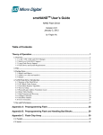
Figure 1 shows the interaction between the different components of a typical USB
application and the USB-FS-Device library.
Figure 1.
USB application hierarchy
User Application
High
Layer
Medium
Layer
usb_pwr
usb_conf
usb_desc
usb_istr
usb_prop
usb_endp
usb_core/usb_init
STM32xxxx_Std
Periph_Driver
&
CMSIS
usb_sil
USB-FS peripheral interface
Low Layer
STM32_USB-FSDevice_Driver
(not modified by user)
Application
Interface
(can be modified
by
y user))
STM32_USB-FS-Device_Lib
usb_int
usb_regs
usb_mem
USB-FS_Device peripheral
Hardware (STM32 + Board)
MSv31504V1
10/85
Doc ID 13465 Rev 12
UM0424
STM32 USB-FS-Device firmware library
As seen in Figure 1, the USB-FS-Device library is divided into two layers:
– STM32_USB-FS_Device_Driver: this layer manages the direct communication with
the USB-FS_Device peripheral and the USB standard protocol. The STM32_USBFS_Device_Driver is compliant with the USB 2.0 specification and is separate from
the standard STM32 standard peripheral library
– Application Interface layer: this layer provides the user with a complete interface
between the library core and the final application.
Note:
The USB-FS peripheral interface layer is loaded (through defines at compile time) and used
as the peripheral interface layer.
The application interface layer and the final application can communicate with the standard
peripherals library to manage the hardware needs of the application.
A detailed description of these layers with coding rules is provided in the next sections.
Figure 2 shows the package organization of the USB-FS-Device library with all the
demonstrations and subfolders.
Figure 2.
USB-FS-Device library package organization
MSxxxxx
Vy
MSv31505V1
Doc ID 13465 Rev 12
11/85
STM32 USB-FS-Device firmware library
3.2
UM0424
USB-FS_Device peripheral interface
Table 4 presents the USB-FS_Device peripheral interface modules.
l
Table 4.
USB-FS_Device peripheral interface modules
File
3.2.1
Description
usb_reg (.h, .c)
Hardware abstraction layer
usb_int.c
Correct transfer interrupt service routine
usb_mem(.h,.c)
Data transfer management (from/to packet memory area)
usb_reg(.h, .c)
The usb_regs module implements the hardware abstraction layer, it offers a set of basic
functions for accessing the USB-FS_Device peripheral registers.
Note:
The available functions have two call versions:
●
As a macro: the call is:
●
As a subroutine: the call is:
_NameofFunction(parameter1, ...)
NameofFunction(parameter1, ...)
Common register functions
The functions in Table 5 can be used to set or get the various common USB-FS_Device
peripheral registers.
Table 5.
Common register functions
Register
CNTR
ISTR
FNR
DADDR
BTABLE
12/85
Function
void SetCNTR (uint16_t wValue)
uint16_t GetCNTR (void)
void SetISTR (uint16_t wValue)
uint16_t GetISTR (void)
uint16_t GetFNR
void SetDADDR
(void)
(uint16_t wValue)
uint16_t GetDADDR
(void)
void SetBTABLE (uint16_t wValue)
uint16_t GetBTABLE (void)
Doc ID 13465 Rev 12
UM0424
STM32 USB-FS-Device firmware library
Endpoint register functions
All operations with endpoint registers can be obtained with the SetENDPOINT and
GetENDPOINT functions. However, many functions are derived from these to offer the
advantage of a direct action on a specific field.
a)
Endpoint set/get value
SetENDPOINT : void SetENDPOINT(uint8_t bEpNum,uint16_t wRegValue)
bEpNum = Endpoint number, wRegValue = Value to write
GetENDPOINT : uint16_t GetENDPOINT(uint8_t bEpNum)
bEpNum = Endpoint number
return value: the endpoint register value
b)
Endpoint TYPE field
The EP_TYPE field of the endpoint register can assume the defined values below:
#define
#define
#define
#define
EP_BULK
EP_CONTROL
EP_ISOCHRNOUS
EP_INTERRUPT
(0x0000)
(0x0200)
(0x0400)
(0x0600)
//
//
//
//
Endpoint
Endpoint
Endpoint
Endpoint
BULK
CONTROL
ISOCHRONOUS
INTERRUPT
SetEPType :
void SetEPType (uint8_t bEpNum, uint16_t wtype)
bEpNum = Endpoint number, wtype = Endpoint type (value from the
above define’s)
GetEPType :
uint16_t GetEPType (uint8_t bEpNum)
bEpNum = Endpoint number
return value: a value from the above define’s
c)
Endpoint STATUS field
The STAT_TX / STAT_RX fields of the endpoint register can assume the defined
values below:
#define EP_TX_DIS
(0x0000)
// Endpoint TX DISabled
#define EP_TX_STALL
(0x0010)
// Endpoint TX STALLed
#define EP_TX_NAK
(0x0020)
// Endpoint TX NAKed
#define EP_TX_VALID
(0x0030)
// Endpoint TX VALID
#define EP_RX_DIS
(0x0000)
// Endpoint RX DISabled
#define EP_RX_STALL
(0x1000)
// Endpoint RX STALLed
#define EP_RX_NAK
(0x2000)
// Endpoint RX NAKed
#define EP_RX_VALID
(0x3000)
// Endpoint RX VALID
SetEPTxStatus : void SetEPTxStatus(uint8_t bEpNum,uint16_t wState)
SetEPRxStatus : void SetEPRxStatus(uint8_t bEpNum,uint16_t wState)
bEpNum = Endpoint number, wState = a value from the above define’s
GetEPTxStatus : uint16_t GetEPTxStatus(uint8_t bEpNum)
GetEPRxStatus : uint16_t GetEPRxStatus(uint8_t bEpNum)
bEpNum = endpoint number
return value:a value from the above define’s
Doc ID 13465 Rev 12
13/85
STM32 USB-FS-Device firmware library
d)
UM0424
Endpoint KIND field
SetEP_KIND
: void SetEP_KIND(uint8_t bEpNum)
ClearEP_KIND : void ClearEP_KIND(uint8_t bEpNum)
bEpNum = endpoint number
Set_Status_Out
: void Set_Status_Out(uint8_t bEpNum)
Clear_Status_Out : void Clear_Status_Out(uint8_t bEpNum)
bEpNum = endpoint number
SetEPDoubleBuff
: void SetEPDoubleBuff(uint8_t bEpNum)
ClearEPDoubleBuff : void ClearEPDoubleBuff(uint8_t bEpNum)
bEpNum = endpoint number
Correct Transfer Rx/Tx fields
ClearEP_CTR_RX : void ClearEP_CTR_RX(uint8_t bEpNum)
ClearEP_CTR_TX : void ClearEP_CTR_TX(uint8_t bEpNum)
bEpNum = endpoint number
e)
Data Toggle Rx/Tx fields
ToggleDTOG_RX : void ToggleDTOG_RX(uint8_t bEpNum)
ToggleDTOG_TX : void ToggleDTOG_TX(uint8_t bEpNum)
bEpNum = endpoint number
f)
Address field
SetEPAdress : void SetEPAddress(uint8_t bEpNum,uint8_t bAddr)
bEpNum = endpoint number
bAddr = address to be set
GetEPAdress : uint8_t GetEPAddress(uint8_t bEpNum)
bEpNum = endpoint number
14/85
Doc ID 13465 Rev 12
UM0424
STM32 USB-FS-Device firmware library
Buffer description table functions
These functions are used in order to set or get the endpoints’ receive and transmit buffer
addresses and sizes.
a)
Tx/Rx buffer address fields
SetEPTxAddr : void SetEPTxAddr(uint8_t bEpNum,uint16_t wAddr);
SetEPRxAddr : void SetEPRxAddr(uint8_t bEpNum,uint16_t wAddr);
bEpNum = endpoint number
wAddr = address to be set (expressed as PMA buffer address)
GetEPTxAddr : uint16_t GetEPTxAddr(uint8_t bEpNum);
GetEPRxAddr : uint16_t GetEPRxAddr(uint8_t bEpNum);
bEpNum = endpoint number
return value : address value (expressed as PMA buffer address)
b)
Tx/Rx buffer counter fields
SetEPTxCount : void SetEPTxCount(uint8_t bEpNum,uint16_t wCount);
SetEPRxCount : void SetEPRxCount(uint8_t bEpNum,uint16_t wCount);
bEpNum = endpoint number
wCount = counter to be set
GetEPTxCount : uint16_t GetEPTxCount(uint8_t bEpNum);
GetEPRxCount : uint16_t GetEPRxCount(uint8_t bEpNum);
bEpNum = endpoint number
return value : counter value
Double-buffered endpoints functions
To obtain high data-transfer throughput in bulk or isochronous modes, double-buffered mode
has to be programmed. In this operating mode some fields of the endpoint registers and
buffer description table cells have different meanings.
To ease the use of this feature several functions have been developed.
●
SetEPDoubleBuff: An endpoint programmed to work in bulk mode can be set as
double-buffered by setting the EP-KIND bit. The function SetEPDoubleBuff()
accomplishes this task:
SetEPDoubleBuff : void SetEPDoubleBuff(uint8_t bEpNum);
bEpNum = endpoint number
●
FreeUserBuffer: In double-buffered mode, the endpoints become mono-directional
and buffer description table cells of the unused direction are applied to handle a second
buffer.
Addresses and counters must be handled in a different way. Rx and Tx Addresses and
counter cells become Buffer0 and Buffer1 cells. Functions dedicated to this operating
mode are provided for in the library.
During a bulk transfer the line fills one buffer while the other buffer is reserved to the
application. A user application has to process data before the arrival of bulk needing a
buffer. The buffer reserved to the application has to be freed in time.
To free the buffer in use from the application, the FreeUserBuffer function is provided:
FreeUserBuffer: void FreeUserBuffer(uint8_t bEpNum, uint8_t
bDir);
bEpNum = endpoint number
Doc ID 13465 Rev 12
15/85
STM32 USB-FS-Device firmware library
a)
UM0424
Double buffer addresses
These functions set or get buffer address value in the buffer description table for
double buffered mode.
SetEPDblBuffAddr : void SetEPDblBuffAddr(uint8_t
bEpNum,uint16_t wBuf0Addr,uint16_t wBuf1Addr);
SetEPDblbuf0Addr : void SetEPDblBuf0Addr(uint8_t
bEpNum,uint16_t wBuf0Addr);
SetEPDblbuf1Addr : void SetEPDblBuf1Addr(uint8_t
bEpNum,uint16_t wBuf1Addr);
bEpNum = endpoint number
wBuf0Addr, wBuf1Addr = buffer addresses (expressed as PMA
buffer addresses)
GetEPDblBuf0Addr : uint16_t GetEPDblBuf0Addr(uint8_t
bEpNum);
GetEPDblbuf1Addr : uint16_t GetEPDblBuf1Addr(uint8_t
bEpNum);
bEpNum = endpoint number
return value :
b)
buffer addresses
Double buffer counters
These functions set or get buffer counter value in the buffer description table for
double buffered mode.
SetEPDblBuffCount: void SetEPDblBuffCount(uint8_t bEpNum, uint8_t
bDir, uint16_t wCount);
SetEPDblBuf0Count: void SetEPDblBuf0Count(uint8_t bEpNum, uint8_t
bDir, uint16_t wCount);
SetEPDblBuf1Count: void SetEPDblBuf1Count(uint8_t bEpNum, uint8_t
bDir, uint16_t wCount);
bEpNum = endpoint number
bDir
= endpoint direction
wCount = buffer counter
GetEPDblBuf0Count : uint16_t GetEPDblBuf0Count(uint8_t bEpNum);
GetEPDblBuf1Count : uint16_t GetEPDblBuf1Count(uint8_t bEpNum);
bEpNum = endpoint number
return value : buffer counter
c)
Double buffer STATUS
The simple and double buffer modes use the same functions to manage the
Endpoint STATUS except for the STALL status for double buffer mode. This
functionality is managed by the function:
SetDouBleBuffEPStall: void SetDouBleBuffEPStall(uint8_t
bEpNum,uint8_t bDir)
bEpNum = endpoint number
bDir
= endpoint direction
16/85
Doc ID 13465 Rev 12
UM0424
3.2.2
STM32 USB-FS-Device firmware library
usb_int (.h , .c)
The usb_int module handles the correct transfer interrupt service routines; it offers the link
between the USB device protocol events and the library.
The STM32 USB-FS_Device peripheral provides two transfer routines:
3.2.3
●
Low-priority interrupt: managed by the function CTR_LP() and used for control,
interrupt and bulk (in simple buffer mode).
●
High-priority interrupt: managed by the function CTR_HP() and used for faster transfer
mode like Isochronous and bulk (in double buffer mode).
usb_mem (.h , .c)
The usb_mem copies a buffer data from the user memory area to the packet memory area
(PMA) and vice versa. It provides two different functions:
●
void UserToPMABufferCopy(uint8_t *pbUsrBuf,uint16_t wPMABufAddr, uint16_t
wNBytes);
●
void PMAToUserBufferCopy(uint8_t *pbUsrBuf,uint16_t wPMABufAddr, uint16_t
wNBytes);
Where:
3.3
●
pbUsrBuf is the pointer to the user memory area generally in the product’s SRAM.
●
wPMABufAddr is the address in PMA (512-byte packet memory area dedicated to
USB).
●
wNBytes is the number of bytes to be copied.
USB-FS-Device_Driver medium layer
Table 6 presents the USB-FS-Device_Driver medium layer modules:
l
Table 6.
USB-FS-Device_Driver medium layer modules
File
Description
usb_init (.h,.c)
USB device initialization global variables
usb_core (.h , .c)
USB protocol management (compliant with chapter 9 of the USB 2.0
specification)
usb_sil (.h,.c)
Simplified functions for read & write accesses to the endpoints (abstraction
layer for the USB-FS_Device peripheral)
usb_def.h / usb_type.h USB definitions and types used in the library
platform_config.h
3.3.1
Defines the hardware depending on the evaluation board used
usb_init(.h,.c)
This module sets initialization routines and global variables that will be used in the library.
3.3.2
usb_core (.h , .c)
This module is the “kernel” of the library. It implements all the functions described in
Chapter 9 of the USB 2.0 specification.
Doc ID 13465 Rev 12
17/85
STM32 USB-FS-Device firmware library
UM0424
The available subroutines cover handling of USB standard requests related to the control
endpoint (ENDP0), offering the necessary code to accomplish the sequence of enumeration
phase.
A state machine is implemented in order to process the different stages of the setup
transactions.
The USB core module also implements a dynamic interface between the standard request
and the user implementation using the structure User_Standard_Requests.
The USB core dispatches the class specific requests and some bus events to user program
whenever it is necessary. User handling procedures are given in the Device_Property
structure.
The different data and function structures used by the kernel are described in the following
paragraphs.
1.
Device table structure
The core keeps device level information in the Device_Table structure. Device_Table
is of the type: DEVICE.
typedef struct _DEVICE {
uint8_t Total_Endpoint;
uint8_t Total_Configuration;
} DEVICE;
2.
Device information structure
The USB core keeps the setup packet from the host for the implemented USB Device in
the Device_Info structure. This structure has the type: DEVICE_INFO.
typedef struct _DEVICE_INFO {
uint8_t USBbmRequestType;
uint8_t USBbRequest;
uint16_t_uint8_t USBwValues;
uint16_t_uint8_t USBwIndexs;
uint16_t_uint8_t USBwLengths;
uint8_t ControlState;
uint8_t Current_Feature;
uint8_t Current_Configuration;
uint8_t Current_Interface;
uint8_t Current_AlternateSetting;
ENDPOINT_INFO Ctrl_Info;
} DEVICE_INFO;
An union uint16_t_uint8_t is defined to easily access some fields in the
DEVICE_INFO in either uint16_t or uint8_t format.
typedef union {
uint16_t w;
struct BW {
uint8_t bb1;
uint8_t bb0;
} bw;
} uint16_t_uint8_t;
18/85
Doc ID 13465 Rev 12
UM0424
STM32 USB-FS-Device firmware library
Description of the structure fields:
–
USBbmRequestType is the copy of the bmRequestType of a setup packet
–
USBbRequest is the copy of the bRequest of a setup packet
–
USBwValues is defined as type: uint16_t_uint8_t and can be accessed through
3 macros:
#define USBwValue USBwValues.w
#define USBwValue0 USBwValues.bw.bb0
#define USBwValue1 USBwValues.bw.bb1
USBwValue is the copy of the wValue of a setup packet
USBwValue0 is the low byte of wValue, and USBwValue1 is the high byte of
wValue.
–
USBwIndexs is defined as USBwValues and can be accessed by 3 macros:
#define USBwIndex USBwIndexs.w
#define USBwIndex0 USBwIndexs.bw.bb0
#define USBwIndex1 USBwIndexs.bw.bb1
USBwIndex is the copy of the wIndex of a setup packet
USBwIndex0 is the low byte of wIndex, and USBwIndex1 is the high byte of
wIndex.
–
USBwLengths is defined as type: uint16_t_uint8_t and can be accessed
through 3 macros:
#define USBwLength USBwLengths.w
#define USBwLength0 USBwLengths.bw.bb0
#define USBwLength1 USBwLengths.bw.bb1
USBwLength is the copy of the wLength of a setup packet
USBwLength0 and USBwLength1 are the low and high bytes of wLength,
respectively.
–
ControlState is the state of the core, the available values are defined in
CONTROL_STATE.
–
Current_Feature is the device feature at any time. It is affected by the
SET_FEATURE and CLEAR_FEATURE requests and retrieved by the
GET_STATUS request. User code does not use this field.
–
Current_Configuration is the configuration the device is working on at any time.
It is set and retrieved by the SET_CONFIGURATION and GET_CONFIGURATION
requests, respectively.
–
Current_Interface is the selected interface.
–
Current_Alternatesetting is the alternative setting which has been selected for
the current working configuration and interface. It is set and retrieved by the
SET_INTERFACE and GET_INTERFACE requests, respectively.
–
Ctrl_Info has type ENDPOINT_INFO.
Since this structure is used everywhere in the library, a global variable
pInformation is defined for easy access to the Device_Info table, it is a pointer to
the DEVICE_INFO structure.
Actually, pInformation = &Device_Info.
Doc ID 13465 Rev 12
19/85
STM32 USB-FS-Device firmware library
3.
UM0424
Device property structure
The USBcore dispatches the control to the user program whenever it is necessary.
User handling procedures are given in an array of Device_Property. The structure has
the type: DEVICE_PROP:
typedef struct _DEVICE_PROP {
void (*Init)(void);
void (*Reset)(void);
void (*Process_Status_IN)(void);
void (*Process_Status_OUT)(void);
RESULT (*Class_Data_Setup)(uint8_t RequestNo);
RESULT (*Class_NoData_Setup)(uint8_t RequestNo);
RESULT (*Class_Get_Interface_Setting)(uint8_t Interface,uint8_t
AlternateSetting);
uint8_t* (*GetDeviceDescriptor)(uint16_t Length);
uint8_t* (*GetConfigDescriptor)(uint16_t Length);
uint8_t* (*GetStringDescriptor)(uint16_t Length);
void* RxEP_buffer; /* This field is not used in current library version.
It is kept only for compatibility with previous versions */
uint8_t MaxPacketSize;
} DEVICE_PROP;
4.
User standard request structure
The User Standard Request Structure is the interface between the user code and the
management of the standard request. The structure has the type:
USER_STANDARD_REQUESTS:
typedef struct _USER_STANDARD_REQUESTS {
void(*User_GetConfiguration)(void);
void(*User_SetConfiguration)(void);
void(*User_GetInterface)(void);
void(*User_SetInterface)(void);
void(*User_GetStatus)(void);
void(*User_ClearFeature)(void);
void(*User_SetEndPointFeature)(void);
void(*User_SetDeviceFeature)(void);
void(*User_SetDeviceAddress)(void);
} USER_STANDARD_REQUESTS;
If the user wants to implement specific code after receiving a standard USB Device
request he has to use the corresponding functions in this structure.
An application developer must implement three structures having the DEVICE_PROP,
Device_Table and USER_STANDARD_REQUEST types in order to manage class
requests and application specific controls. The different fields of these structures are
described in Section 3.3.4: usb_type.h / usb_def.h.
20/85
Doc ID 13465 Rev 12
UM0424
3.3.3
STM32 USB-FS-Device firmware library
usb_sil(.h, .c)
The usb_sil module implements an additional abstraction layer for USB-FS_Device
peripheral. It offers simple functions for accessing the Endpoints for Read and Write
operations.
Endpoint simplified write function
The write operation to an endpoint can be performed through the following function:
void USB_SIL_Write(uint32_t EPNum, uint8_t* pBufferPointer, uint32_t
wBufferSize);
The parameters of this function are:
●
EPNum: Number of the IN endpoint related to the write operation
●
pBufferPointer: Pointer to the user buffer to be written to the IN endpoint.
●
wBufferSize: Number of data bytes to be written to the IN endpoint.
Depending on the peripheral interface, this function gets the address of the endpoint buffer
and performs the packet write operation.
Endpoint simplified read function
The read operation from an endpoint can be performed through the following function:
uint32_t USB_SIL_Read(uint32_t EPNum, uint8_t* pBufferPointer);
The parameters of this function are:
●
EPNum: Number of the OUT endpoint related to the read operation
●
pBufferPointer: Pointer to the user buffer to be filled with the data read form the OUT
endpoint.
Depending on the peripheral interface, this function performs two successive operations:
1.
Gets the number of data received from the host on the related OUT endpoint
2.
Copies the received data from the USB dedicated memory to the pBufferPointer
address.
Then the function returns the number of received data bytes to the user application.
3.3.4
usb_type.h / usb_def.h
These files provides the main types and USB definitions used in the library.
3.3.5
platform_config.h
This file is responsible for offering a specific configuration for each eval board. This file
should be copied to the application folder, where it can then be configured by the user.
3.4
Application interface
The modules of the Application interface are provided as a template, they must be tailored
by the application developer for each application. Table 7 shows the different modules used
in the application interface.
Doc ID 13465 Rev 12
21/85
STM32 USB-FS-Device firmware library
Table 7.
UM0424
Application interface modules
File
3.4.1
Description
usb_conf.h
USB-FS_Device configuration file
usb_desc (.h, .c)
USB-FS_Device descriptors
usb_prop (.h, .c)
USB-FS_Device application-specific properties
usb_endp.c
Correct transfer interrupt handler routines for non-control endpoints
usb_istr (.h,.c)
USB-FS_Device interrupt handler functions
usb_pwr (.h, .c)
USB-FS_Device power and connection management functions
usb_conf(.h)
The usb_conf.h is used to customize the USB demos and to configure the device as follows:
3.4.2
●
Define the number of endpoints to be used (through the define EP_NUM).
●
Enable the use of Endpoints and event callback routines by commenting the relative
callback define (i.e. comment the define EP1_IN_Callback to enable and use this
function when a correct transfer occurs on endpoint 1, comment the define
INTR_SOFINTR_Callback in order to use and implement this function when an SOF
interrupt occurs...). When a callback is to be used, its relative define in usb_conf.h file
should be commented. Then, it should be implemented with the same name in the user
application (no need to declare the callback function prototype as it is already declared
in the usb_istr.h file). You can use the file usb_conf.h to:
–
Configure the BTABLE and all endpoint addresses in the PMA (by modifying
and/or adding relative address defines: BTABLE_ADDRESS, ENDP0_RXADDR,
ENDP0_TXADDR ...).
–
Define the interrupts to enable them through the interrupt mask IMR_MSK.
usb_desc (.h, .c)
The usb_desc.c file should contain all the USB descriptors related to the application. The
user has to set these descriptors according to the application proprieties and class.
In all available demos in the “STM32 USB-FS_Device developer kit” there is an example
implementing a unique serial number string descriptor based on the STM32 Device Unique
ID register (12 digits).
The default value of the serial number string descriptor is “STM32” and during the USB
initialization the Get_SerialNum() function reads the Device Unique ID register and sets
the serial number string descriptor.
For more details regarding the Device Unique ID register, please refer to Table 4.
22/85
Doc ID 13465 Rev 12
UM0424
3.4.3
STM32 USB-FS-Device firmware library
usb_prop (.h , .c)
The usb_prop module is used for implementing the Device_Property, Device_Table and
USER_STANDARD_REQUEST structures used by the USB core.
Device property implementation
The device property structure fields are described below:
●
void Init(void): Init procedure of the USB-FS_Device peripheral. It is called once at
the start of the application to manage the initialization process.
●
void Reset(void): Reset procedure of the USB peripheral. It is called when the
macrocell receives a RESET signal from the bus. The user program should set up the
endpoints in this procedure, in order to set the default control endpoint and enable it to
receive.
●
void Process_Status_IN(void): Callback procedure, it is called when a status in a
stage is finished. The user program can take control with this callback to perform classand application-related processes.
●
void Process_Status_OUT(void): Callback procedure, it is called when a status out
stage is finished. As with Process_Status_IN, the user program can perform actions
after a status out stage.
●
RESULT (see note below) *(Class_Data_Setup)(uint8_t RequestNo): Callback
procedure, it is called when a class request is recognized and this request needs a
data stage. The core cannot process such requests. In this case, the user program gets
the chance to use custom procedures to analyze the request, prepare the data and
pass the data to the USB-FS_Device core for exchange with the host. The parameter
RequestNo indicates the request number. The return parameter of this function has the
type: RESULT. It indicates the result of the request processing to the core.
●
RESULT (*Class_NoData_Setup)(uint8_t RequestNo) Callback procedure, it is
called when a non-standard device request is recognized, that does not need a data
stage. The core cannot process such requests. The user program can have the chance
to use custom procedures to analyze the request and take action. The return
parameter of this function has type: RESULT. It indicates the result of the request
processing to the core.
●
RESULT (*Class_GET_Interface_Setting)(uint8_t Interface, uint8_t
AlternateSetting): This routine is used to test the received set interface standard
request. The user must verify the "Interface" and "AlternateSetting" according to their
own implementation and return the USB_UNSUPPORT in case of error in these two
fields.
●
uint8_t* GetDeviceDescriptor(uint16_t Length): The core gets the device descriptor.
●
uint8_t* GetConfigDescriptor(uint16_t Length): The core gets the configuration
descriptor.
●
uint8_t* GetStringDescriptor(uint16_t Length): The core gets the string descriptor.
●
uint16_t MaxPacketSize: The maximum packet size of the device default control
endpoint.
Doc ID 13465 Rev 12
23/85
STM32 USB-FS-Device firmware library
Note:
UM0424
The RESULT type is the following:
typedef enum _RESULT {
USB_SUCCESS = 0,/* request process sucessfully */
USB_ERROR,
/* error
USB_UNSUPPORT, /* request not supported
USB_NOT_READY/* The request process has not been finished,*/
/* endpoint will be NAK to further requests*/
} RESULT;
Device endpoint implementation
Description of the structure fields:
●
Total_Endpoint is the number of endpoints the USB application uses.
●
Total_Configuration is the number of configurations the USB application has.
USER_STANDARD_REQUEST implementation
This structure is used to manage the user implementation after receiving all standard
requests (except Get descriptors). The fields of this structure are:
3.4.4
●
void (*User_GetConfiguration)(void): Called after receiving the Get Configuration
Standard request.
●
void (*User_SetConfiguration)(void): Called after receiving the Set Configuration
Standard request.
●
void (*User_GetInterface)(void): Called after receiving the Get interface Standard
request.
●
void (*User_SetInterface)(void): Called after receiving the Set interface Standard
request.
●
void (*User_GetStatus)(void): Called after receiving the Get interface Standard
request.
●
void (*User_ClearFeature)(void): Called after receiving the Clear Feature Standard
request.
●
void (*User_SetEndPointFeature)(void): Called after receiving the set Feature
Standard request (only for endpoint recipient).
●
void (*User_SetDeviceFeature)(void): Called after receiving the set Feature Standard
request (only for Device recipient).
●
void (*User_SetDeviceAddress)(void): Called after receiving the set Address
Standard request.
usb_endp (.c)
USB_endp module is used for:
●
Handling the CTR “correct transfer” routines for endpoints other than endpoint 0 (EP0)
for the USB-FS_Device peripheral
For enabling the processing of these callback handlers a pre-processor switch named
EPx_IN_Callback (for IN transfer) or EPx_OUT_Callback (for OUT transfer) or
EPx_RX_ISOC_CALLBACK (for Isochronous Out transfer) must be defined in the
USB_conf.h file.
24/85
Doc ID 13465 Rev 12
UM0424
3.4.5
STM32 USB-FS-Device firmware library
usb_istr(.c)
USB_istr module provides a function named USB_Istr() which handles all USB
interrupts.
For each USB interrupt source, a callback routine named XXX_Callback (for example,
RESET_Callback) is provided in order to implement a user interrupt handler. To enable the
processing of each callback routines, a preprocessor switch named XXX_Callback must
be defined in the USB configuration file USB_conf.h.
3.4.6
usb_pwr (.h , .c)
This module manages the power management of the USB device. It provides the functions
shown in Table 8.
Table 8.
Power management functions
Function name
Description
RESULT Power_on(void)
Handle switch-on conditions
RESULT Power_off(void)
Handle switch-off conditions
void Suspend(void)
Sets suspend mode operation conditions
void Resume(RESUME_STATE eResumeSetVal)
Handle wakeup operations
3.5
Implementing a USB-FS_Device application using the
STM32 USB-FS-Device library
3.5.1
Implementing a no-data class-specific request
All class-specific requests without a data transfer phase implement the field
RESULT (*Class_NoData_Setup)(uint8_t RequestNo) of the structure device
property. The USBbRequest of the request is available in the RequestNo parameter and all
other request fields are stored in the device info structure.
The user has to test all request fields. If the request is compliant with the class to implement,
the function returns the USB_SUCCESS result. However if there is a problem in the request,
the function returns the UNSUPPORT result status and the library responds with a STALL
handshake.
3.5.2
How to implement a data class-specific request
In the event of class requests requiring a data transfer phase, the user implementation
reports to the USB-FS-Device library the length of the data to transfer and the data location
in the internal memory (RAM if the data is received from the host and, RAM or Flash
memory if the data is sent to the host). This type of request is managed in the function:
RESULT (*Class_Data_Setup)(uint8_t RequestNo).
For each class data request the user has to create a specific function with the format:
uint8_t* My_First_Data_Request (uint16_t Length)
If this function is called with the Length parameter equal to zero, it sets the
pInformation->Ctrl_Info.Usb_wLength field with the length of data to transfer and
Doc ID 13465 Rev 12
25/85
STM32 USB-FS-Device firmware library
UM0424
returns a NULL pointer. In other cases it returns the address of the data to transfer. The
following C code shows a simple example:
uint8_t* My_First_Data_Request (uint16_t Length)
{
if (Length == 0)
{
pInformation->Ctrl_Info.Usb_wLength = My_Data_Length;
return NULL;
}
else
return (&My_Data_Buffer);
}
The function RESULT (*Class_Data_Setup)(uint8_t RequestNo) manages all data
requests as described in the following C code:
RESULT Class_Data_Setup(uint8_t RequestNo)
{
uint8_t*(*CopyRoutine)(uint16_t);
CopyRoutine = NULL;
if (My_First_Condition)// test the filds of the first request
CopyRoutine = My_First_Data_Request;
else if(My_Second_Condition) // test the filds of the second request
CopyRoutine = My_Second_Data_Request;
/*
...
same implementation for each class data requests
...
*/
if (CopyRoutine == NULL) return USB_UNSUPPORT;
pInformation->Ctrl_Info.CopyData = CopyRoutine;
pInformation->Ctrl_Info.Usb_wOffset = 0;
(*CopyRoutine)(0);
return USB_SUCCESS;
} /*End of Class_Data_Setup */
3.5.3
How to manage data transfers in non-control endpoint
The management of the data transfer using a pipe that is not the default one (Endpoint 0)
can be managed in the usb_end.c file.
The user has to uncomment the line corresponding to the endpoint (with direction) in the file
usb_conf.h.
26/85
Doc ID 13465 Rev 12
UM0424
4
Joystick mouse demo
Joystick mouse demo
This demo runs on thefollowing STMicroelectronicsevaluation boards, and can be easily
tailored to any other hardware:
●
STM3210B-EVAL
●
STM3210E-EVAL
●
STM32L152-EVAL
●
STM32373C-EVAL
●
STM32303C-EVAL
●
STM32L152D-EVAL
To select the STMicroelectronics evaluation board used to run the demo, uncomment the
corresponding line in the platform_config.h file.
4.1
General description
A USB mouse (human interface device –HID– class) is a simple example of a complete USB
application. The joystick mouse uses only one interrupt endpoint (endpoint 1 in the IN
direction). After normal enumeration, the host requests the HID report descriptor of the
mouse. This specific descriptor is presented (with standard descriptors) in the usb_desc.c
file.
To get the mouse pointer position the host requests four bytes of data with the format shown
in Figure 3, using pipe 1 (endpoint 1).
Figure 3.
Format of the four data bytes
n
8
9
n
AI
The purpose of the mouse demo is to set the X and Y values according to the user actions
with a joystick button. The JoyState() function gets the user actions and returns the
direction of the mouse pointer. The Joystick_Send() function formats the data to send to
the host and validates the data transaction phase.
Note:
See the hw_config.c file for details on the functions.
4.2
STM32 low-power management in suspend mode
To give an example of power management during the USB suspend/resume events, the
joystick mouse demo supports the STM32 Stop mode entry and exit.
The STM32 Stop mode is based on the Cortex-M3 deepsleep mode combined with
peripheral clock gating. In Stop mode, all clocks in the 1.8 V domain are stopped, the PLLs,
HSI RC and HSE crystal oscillators are disabled. Wakeup from the Stop mode is possible
only using one EXTI line in interrupt or event mode.
Doc ID 13465 Rev 12
27/85
Joystick mouse demo
UM0424
In this demo, during Stop mode, the voltage regulator is configured in low-power mode to
reduce the power consumption and EXTI line 18 (USB-FS_Device Wakeup line) is used for
wakeup in interrupt mode.
When a suspend event occurs on the bus, the USB-FS-Device library dispatches the
request and calls the Enter_LowPowerMode() function (file hw_config.c). In this function,
the STM32 is put in Stop mode.
The STM32 remains in Stop mode until it receives a wakeup (resume) event on the bus. In
this case, EXTI line 18 is activated and wakes up the STM32. After wakeup, the USB-FSDevice library calls the Leave_LowPowerMode() function (file hw_config.c) to reconfigure
the clock (re-enable the HSE and PLL).
To test this feature and measure the power consumption during USB-FS_Device suspend,
connect current meter to the VDD jumper listed in Table 9.
Table 9.
Eval board power consumption related jumpers
Eval board name
Jumper
STM3210B-EVAL
JP9
STM3210E-EVAL
JP12
STM32L152-EVAL
JP4
STM32L152D-EVAL
JP10
STM32373C-EVAL
JP15
STM32303C-EVAL
JP12
Note:
On the PC side, use the USB HS Electrical Test Toolkit available for free from usb.org to put
the STM32 in the suspend/resume state.
4.3
Remote wakeup implementation
Remote wakeup is the ability of a USB device to bring a suspended bus back to the active
condition. A device that supports remote wakeup reports this capability to the PC using the
bmAttributes field of the configuration descriptor (bit D5 set to 1).
In the Joystick demo the key push-button is used as the remote wakeup source. The key
button is connected to EXTI line. The table below summarizes the key push button
assignment for each eval board.
Table 10.
Key push button assignment
Eval board name
28/85
EXTI line number
STM3210B-EVAL
EXTI line 9 (GPIO PB.09)
STM3210E-EVAL
EXTI line 8 (GPIO PG.08)
STM32L152-EVAL / STM32L152D-EVAL
EXTI line 0 (GPIO PA.00)
STM32373C-EVAL
EXTI line 2 (GPIO PA.02)
STM32303C-EVAL
EXTI line 6 (GPIO PE.06)
Doc ID 13465 Rev 12
UM0424
Joystick mouse demo
When the key is pressed, the corresponding EXTI ISR is called to initiate the USB device
power management state machine using the Resume() function. Note that remote wakeup
could be disabled by the PC host using the set_feature request, so the EXTI ISR tests the
current feature and sends the remote wake-up signal to the PC only if the feature is enabled.
Doc ID 13465 Rev 12
29/85
Custom HID demo
5
UM0424
Custom HID demo
This demo runs on the following STMicroelectronics evaluation boards, and can be easily
tailored to any other hardware:
●
STM3210B-EVAL
●
STM3210E-EVAL
●
STM32L152-EVAL
●
STM32373C-EVAL
●
STM32303C-EVAL
●
STM32L152D-EVAL
To select the STMicroelectronics evaluation board used to run the demo, uncomment the
corresponding line in the platform_config.h file.
5.1
General description
The HID (human interface device) class primarily consists of devices that are used by
humans to control the operation of computer systems. Typical examples of HID class
devices are standard mouse devices, keyboards, Bluetooth adaptors etc.
HID Input/Output reports can be exchanged both over the interrupt endpoint, and over the
default endpoint (Get_/Set_Report requests).
The custom HID demo is a simple HID demo provided with a small PC applet to give an
example of how to create a customized HID based on the native Windows HID driver. It
consists of simple data exchanges between the STM32 evaluation board and the PC Host
using two interrupt pipes (IN and OUT).
The custom HID demo implements feature request handling, which allows the user to send
a control commands to the device. This command is sent through endpoint 0, and must be
treated as a set_report request.
For more details on the HID device class, please refer to the “Device Class Definition for HID
1.11” available from the usb.org website.
The data exchanged is related to LED commands, push-button state reports and ADC
conversion values.
For more details on how to use the PC applet of the custom HID, please refer to the UM0551
user manual “USB HID demonstrator” available from the STMicroelectronics microcontroller
website www.st.com.
5.2
Descriptor topology
The custom HID topology is based on two interrupt pipes used to handle the data transfer
for seven different reports. The following chart shows the custom HID topology.
30/85
Doc ID 13465 Rev 12
UM0424
Custom HID demo
Figure 4.
Custom HID topology
$EVICE
DESCRIPTOR
#ONFIGURATION
DESCRIPTOR
)NTERFACE
DESCRIPTOR
%NDPOINT/54
DESCRIPTOR
%NDPOINT).
DESCRIPTOR
()$
DESCRIPTOR
2EPORT
DESCRIPTORS
AI
Each report descriptor is related to a specific component in the evaluation board (LEDs,
Push-buttons or ADC). The following section describes the functionality of these reports.
5.3
Custom HID implementation
5.3.1
LED control
The STM32 evaluation boards have four LEDs. In the custom HID demo, each LED
corresponds to a specific report (reports 1 to 4), and the LED states (ON/OFF) are set by
the PC applet. Reports generated by the host to the device are transmitted through either
the interrupt (OUT) endpoint or the default endpoint (Control) using the Set_Report request.
In the PC applet, the output mode is set by default to SET_REPORT, and interrupt transfer is
applied.When the device receives data on endpoint 1 OUT, the EP1_OUT_Callback()
function is called to dispatch the received state to the corresponding LED according to the
report number.
When switching to the SET_FEATURE mode, control transfer is applied. The
CustomHID_SetReport_Feature() function is called, and the host initiates a control endpoint
transfer, which causes IN and OUT reports to be sent and received. Report_Buf[] contains
both the report and the number of bytes to transmit.
The data received has the format shown in Figure 5, where:
●
Report Num: report number from 1 to 4.
●
LED state:
–
0 -> LED off
–
1 -> LED on
Doc ID 13465 Rev 12
31/85
Custom HID demo
Figure 5.
UM0424
Data OUT format
2EPORT.UM
,%$STATE
AI
5.3.2
Push-button state report
The states of the Key and Tamper push-buttons on the STM32 evaluation boards (except for
the STM32L152-EVAL board where Right and Left joystick buttons are used) are reported to
the PC host using the endpoint 1 IN.
The Key push-button (or Right push-button on the STM32L152-EVAL board) corresponds to
Report 5 and the Tamper push-button (or Left push-button on the STM32L152 board) to
Report 6. When one of the two push-buttons is pressed, the device sends the related report
number and the push-button state to the host. Figure 6 shows the used format, where:
●
Report Num: report number 5 or 6
●
Button state: 1 -> button pressed
Figure 6.
Data IN Format
2EPORT.UM
"UTTONSTATE
AI
5.3.3
ADC-converted data transfer
This part of the demo consists in transferring the result of the converted voltage connected
to the potentiometer of the evaluation board to the PC host. The ADC is configured in
continuous mode with DMA data transfer to a RAM variable (ADC_ConvertedValueX). After
each conversion the converted value is tested against an old one
(ADC_ConvertedValueX_1) and if there is a difference between the two values
(potentiometer value changed by a user), the new value is sent to the PC using the
endpoint 1 IN.
Note:
32/85
The data format is the same as the one used for the push-buttons, but the report number (7)
is followed by the MSB of the ADC conversion result.
Doc ID 13465 Rev 12
UM0424
6
Mass storage demo
Mass storage demo
This demo runs on the following STMicroelectronics evaluation boards, and can be easily
tailored to any other hardware:
●
STM3210B-EVAL
●
STM3210E-EVAL
●
STM32L152-EVAL
●
STM32373C-EVAL
●
STM32303C-EVAL
●
STM32L152D-EVAL
To select the STMicroelectronics evaluation board used to run the demo, uncomment the
corresponding line in the platform_config.h file.
6.1
General description
The mass storage demo gives a typical example of how to use the STM32 USB-FS_Device
peripheral to communicate with the PC host using bulk transfer.
This demo supports the BOT (bulk only transfer) protocol and all needed SCSI (small
computer system interface) commands, and is compatible with Windows XP (SP1, SP2,
SPI3), Windows 2000 (SP4), Windows Vista and Windows 7.
6.2
Mass storage demo overview
The mass storage demo complies with USB 2.0 and USB mass storage class (bulk-only
transfer subclass) specifications. After running the application, the user just has to plug the
USB cable into a PC Host and the device is automatically detected without any additional
drive (with Win 2000, XP, Vista and Windows 7). A new removable drive appears in the
system window and write/read/format operations can be performed as with any other
removable drive (see Figure 7).
Figure 7.
New removable disk in Windows
AI
Table 11 gives details of the memory support used for each eval board.
Doc ID 13465 Rev 12
33/85
Mass storage demo
Table 11.
UM0424
Eval board memory support
Eval board
Memory support
IP interface
STM3210E-EVAL
MicroSD and NAND Flash
SDIO and FSMC
STM3210B-EVAL
MicroSD
SPI
STM32L152-EVAL
MicroSD
SPI
STM32L152D-EVAL
MicroSD
SDIO
STM32373C-EVAL
MicroSD
SPI
STM32303C-EVAL
MicroSD
SPI
Note:
All related firmware used to initialize, read from and write to the media are available in the
stm32xxx_eval_sdio_sd.c.c/.h, stm32xxx_eval_spi_sd.c/.h and fsmc_nand.c/.h files.
Note:
For mass storage class, the device firmware does not need to know or take into account the
file system the host is using. The firmware just stores and sends blocks of data as requested
by the host.
6.3
Mass storage protocol
6.3.1
Bulk-only transfer (BOT)
The BOT protocol uses only bulk pipes to transfer commands, status and data (no interrupt
or control pipes). The default pipe (pipe 0, or in other words, Endpoint 0) is only used to
clear the bulk pipe status (clear STALL status) and to issue the two class-specific requests:
Mass Storage reset and Get Max LUN.
34/85
Doc ID 13465 Rev 12
UM0424
Mass storage demo
Command transfer
To send a command, the host uses a specific format called command block wrapper (CBW).
The CBW is a 31-byte length packet. Table 12 shows the different fields of a CBW.
Table 12.
CBW packet fields
7
6
5
4
3
2
0-3
dCBWSignature
4-7
dCBWTag
8-11
dCBWDataTransferLength
12
bmCBWFlags
13
14
Reserved (0)
0
bCBWLUN
Reserved (0)
15-30
1
bCBWCBLength
CBWCB
●
dCBWSignature: 43425355 : USBC (in little Endian)
●
dCBWTag: The host specifies this field for each command. The device should return
the same dCBWTag in the associated status.
●
dCBWDataTransferLength: total number of bytes to transfer (expected by the host).
●
bmCBWFlags: This field is used to specify the direction of the data transfer (if any).
The bits of this field are defined as follows:
–
Bit 7: Direction bit:
0: Data Out transfer (host to device).
1: Data In transfer (device to host).
Note: The device ignores this bit if the dCBWDataTransferLength field is
cleared to zero.
–
Bits 6:0: reserved (cleared to zero).
●
bCBWLUN: concerned Logical Unit number.
●
bCBWCBLength: this field specify the length (in bytes) of the command CBWCB.
●
CBWCB: the command block to be executed by the device.
Doc ID 13465 Rev 12
35/85
Mass storage demo
UM0424
Status transfer
To inform the host about the status of each received command, the device uses the
command status wrapper (CSW). Table 13 shows the different fields of a CSW.
Table 13.
CSW packet fields
7
6
5
4
3
0-3
dCSWSignature
4-7
dCSWTag
8-11
dCSWDataResidue
12
bCSWStatus
2
1
0
●
dCSWSignature: 53425355 USBS (little Endian).
●
dCSWTag: the device sets this field to the received value of dCBWTag in the
concerned CBW.
●
dCSWDataResidue: the difference between the expected data (the value of the
dCBWDataTransferLength field of the concerned CBW) and the real value of the data
received or sent by the device.
●
bCSWStatus: the status of the concerned command. This field can assume one of the
three non-reserved values shown in Table 14.
Table 14.
Command block status values
Value
Description
0x00
Command passed
0x01
Command failed
0x02
Phase error
0x03=>0xFF
Reserved
Data transfer
The data transfer phase is specified by the dCBWDataTransferLength and bmCBWFlags of
the correspondent CBW. The host attempts to transfer the exact number of bytes to or from
the device.
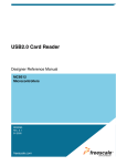
The diagram shown in Figure 8 shows the state machine of a BOT transfer.
Note:
36/85
For more information about the BOT protocol, please refer to the “Universal Serial Bus Mass
Storage Class Bulk-Only Transport” specification.
Doc ID 13465 Rev 12
UM0424
Mass storage demo
Figure 8.
BOT state machine
2EADY
#OMMAND
TRANSPORT
#"7
$ATA).
TOTHEHOST
$ATA/54
FROMTHEHOST
3TATUS
TRANSPORT
#37
AI
Doc ID 13465 Rev 12
37/85
Mass storage demo
6.3.2
UM0424
Small computer system interface (SCSI)
The SCSI command set is designed to provide efficient peer-to-peer operation of SCSI
devices like, for example, hard desks, tapes and mass storage devices. In other words these
are used to ensure the communication between an SCSI device and an operating system in
a PC host.
Table 15 shows SCSI commands for removable devices. Not all commands are shown. For
more information, please refer to the SPC and RBC specifications.
Table 15.
SCSI command set
OpCode
Command
support(1)
Inquiry
0x12
M
Get device information
SPC-2
Read Format
Capacities
0x23
M
Report current media capacity and
formattable capacities supported by
medium
SPC-2
Mode Sense (6)
0x1A
M
Report parameters to the host
SPC-2
M
Report parameters to the host
SPC-2
SPC-2
Command name
Mode Sense (10)
Description
Prevent\ Allow
Medium Removal
0x1E
M
Prevent or allow the removal of media from
a removable media device
Read (10)
0x28
M
Transfer binary data from the medium to
the host
RBC
Read Capacity
(10)
0x25
M
Report current medium capacity
RBC
Request Sense
0x03
O
Transfer status sense data to the host
Start Stop Unit
0x1B
M
Enable or disable the Logical Unit for
medium access operations and controls
certain power conditions
RBC
Test Unit Ready
0x00
M
Request the device to report if it is ready
SPC-2
Verify (10)
0x2F
M
Verify data on the medium
RBC
Write (10)
0x2A
M
Transfer binary data from the host to the
medium
RBC
1. Command Support key: M = support is mandatory, O = support is optional.
38/85
Reference
Doc ID 13465 Rev 12
SPC-2
UM0424
Mass storage demo
6.4
Mass storage demo implementations
6.4.1
Hardware configuration interface
The hardware configuration interface is a layer between the USB application (in our case the
Mass Storage demo) and the internal/external hardware of the STM32 microcontroller. This
internal and external hardware is managed by the STM32 standard peripheral library, so
from the firmware point of view, the hardware configuration interface is the firmware layer
between the USB application and the standard peripheral library. Figure 9 shows the
interaction between the different firmware components and the hardware environment.
Figure 9.
Hardware and firmware interaction diagram
53"&3$EVICE
APPLICATION
53"&3$EVICELIBRARY
34-
3TANDARD
PERIPHERAL
LIBRARY
53"&3?$EVICEPERIPHERAL
OR
/4'&3?$EVICEPERIPHERAL
(ARDWARE34-EVALUATIONBOARD
(ARDWARECONFIGINTERFACE
AIC
The hardware configuration layer is represented by the two files HW_config.c and
HW_config.h. For the Mass Storage demo, the hardware management layer manages the
following hardware requirements:
●
System and USB-FS_Device peripheral clock configuration
●
Read and write LED configuration
●
LED command
●
Initialize the memory medium
●
Get the characteristics of the memory medium (the block size and the memory
capacity)
Doc ID 13465 Rev 12
39/85
Mass storage demo
6.4.2
UM0424
Endpoint configurations and data management
This section provides a description of the configuration and the data flow according to the
transfer mode.
Endpoint configurations
The endpoint configurations should be done after each USB reset event, so this part of code
is implemented in the MASS_Reset function (file usp_prop.c).
For all STM32 except Connectivity line devices:
To configure endpoint 0 it is necessary to:
●
Configure endpoint 0 as the default control endpoint
●
Configure the endpoint 0 Rx and Tx count and buffer addresses in the BTABLE
(usb_conf.h file)
●
Configure the endpoint Rx status as VALID and the Tx status as NAK.
The bulk pipes (endpoints 1 and 2) are configured as follows:
40/85
1.
Configure endpoint 1 as bulk IN
2.
Configure the endpoint 1 Tx count and data buffer address in the BTABLE (usb_conf.h
file)
3.
Disable the endpoint 1 Rx
4.
Configure the endpoint 1 Tx status as NAK
5.
Configure the endpoint 2 as bulk OUT
6.
Configure the endpoint 2 Rx count and data buffer address in the BTABLE (usb_conf.h
file)
7.
Disable the endpoint 2 Tx
8.
Configure the endpoint 2 Rx status as VALID.
Doc ID 13465 Rev 12
UM0424
Mass storage demo
Data management
Data management consists of the transfer of the needed data directly from the specified
data buffer address in the USB memory, according to the related endpoint (IN:
ENDP1TXADDR; OUT: ENDP2RXADDR). For these transfers, the following two functions
are used (usb_sil.c file):
6.4.3
●
USB_SIL_Read (): this function transfers the received bytes from the USB memory to
the internal RAM. This function is used to copy the data sent by the host to the device.
The number of received data bytes is determined into the function (not passed as
parameter) and this value is returned by the function at the end of the operation.
●
USB_SIL_Write (): this function transfers the specified number of bytes from the
internal RAM to the USB memory. This function is used to send the data from the
device to the host.
Class-specific requests
The Mass Storage Class specification describes two class-specific requests:
Bulk-only mass storage reset
This request is used to reset the Mass Storage device and its associated interface. This
class-specific request makes the device ready for the next CBW sent by the PC host.
To issue the bulk-only mass storage reset, the host issues a device request on the default
pipe (endpoint 0) of:
●
bmRequestType: Class, Interface, Host to device
●
bRequest field set to 0xFF
●
wValue field set to 0
●
wIndex field set to the interface number (0 for this implementation)
●
wLength field set to 0
This request is implemented as a no-data class-specific request in the
MASS_NoData_Setup() function (usb_prop.c file).
After receiving this request, the device clears the data toggle of the two bulk endpoints,
initializes the CBW signature to the default value and sets the BOT state machine to the
BOT_IDLE state to be ready to receive the next CBW.
GET MAX LUN request
A Mass Storage Device may implement several logical units that share common device
characteristics. The host uses bCBWLUN to designate which logical unit of the device is the
destination of the CBW.
The Get Max LUN device request is used to determine the number of logical units supported
by the device.
Doc ID 13465 Rev 12
41/85
Mass storage demo
UM0424
To issue a Get Max LUN request the host must issue a device request on the default pipe
(endpoint 0) of:
●
bmRequestType: Class, Interface, Host to device
●
bRequest field set to 0xFE
●
wValue field set to 0
●
wIndex field set to the interface number (0 for this implementation)
●
wLength field set to 1
This request is implemented as a data class-specific request in the MASS_Data_Setup()
function (usb_prop.c file). Note that in case of the STM3210E-EVAL board two LUNs are
supported
6.4.4
Standard request requirements
To be compliant with the BOT specification the device must respond to the two following
requirements after receiving the same standard requests:
6.4.5
●
When the device switches from the unconfigured to the configured state, the data
toggle of all endpoints must be cleared. This requirement is served by the
Mass_Storage_SetConfiguration() function in the usb_prop.c file.
●
When the host sends a CBW command with an invalid signature or length, the device
must keep endpoints 1 and 2 both as STALL until it receives the Mass Storage Reset
class-specific request. This functionality is managed by the
Mass_Storage_ClearFeature() function in the usb_prop.c file.
BOT state machine
To provide the BOT protocol, a specific state machine with five states is implemented. The
states are described below:
42/85
●
BOT_IDLE: this is the default state after a USB reset, Bulk-Only Mass Storage Reset
or after sending a CSW. In this state the device is ready to receive a new CBW from the
host
●
BOT_DATA_OUT: the device enters this state after receiving a CBW with data flow
from the host to the device
●
BOT_DATA_IN: the device enters this state after receiving a CBW with data flow from
the device to the host
●
BOT_DATA_IN_LAST: the device enters this state when sending the last of the data
asked for by the host
●
BOT_CSW_SEND: the device moves to this state when sending the CSW. When the
device is in this state and a correct IN transfer occurs, the device moves to the
BOT_IDLE state to be able to receive the next CBW
●
BOT_ERROR: Error state
Doc ID 13465 Rev 12
UM0424
Mass storage demo
The BOT state machine is managed using the functions described below (usb_bot.c and
usb_bot.h firmware files):
6.4.6
●
Mass_Storage_In (); Mass_Storage_Out (): these two functions are called when a
correct transfer (IN or OUT) occurs. The aim of these two functions is to provide the
next step after receiving/sending a CBW, data or CSW
●
CBW_Decode (): this function is used to decode the CBW and to dispatch the firmware
to the corresponding SCSI command
●
DataInTransfer (): this function is used to transfer the characteristic device data to the
host
●
Set_CSW (): this function is used to set the CSW fields with the needed parameters
according to the command execution
●
Bot_Abort (): this function is used to STALL the endpoints 1 or 2 (or both) according to
the Error occurring in the BOT flow
SCSI protocol implementation
The aim of the SCSI Protocol is to provide a correct response to all SCSI commands
needed by the operating system on the PC host. This section details the method of
management for all implemented SCSI commands.
●
INQUIRY command (OpCode = 0x12):
Send the needed inquiry page data (in this demo only page 0 and the standard page
are supported) with the needed data length according to the ALLOCATION LENGTH
field of the command.
●
SCSI READ FORMAT CAPACITIES command (OpCode = 0x23):
Send the Read Format Capacity data response (ReadFormatCapacity_Data[ ]
from the SCSI_data.c file) after checking the presence of the medium. If no medium
has been detected a MEDIUM_NOT_PRESENT error is returned to force the host to
update its internal parameters.
●
SCSI READ CAPACITY (10) command (OpCode = 0x25):
Send the Read Capacity (10) data response (ReadCapacity10_Data[ ] from the
SCSI_data.c file) after checking the presence of the medium. If no medium has been
detected a MEDIUM_NOT_PRESENT error is returned to force the host to update its
internal parameters.
●
SCSI MODE SENSE (6) command (OpCode = 0x1A):
Send the Mode Sense (6) data response (Mode_Sense6_data[ ] from the
SCSI_data.c file).
●
SCSI MODE SENSE (10) command (OpCode = 0x5A):
Send the Mode Sense (10) data response (Mode_Sense10_data[
SCSI_data.c file).
●
] from the
SCSI REQUEST SENSE command (OpCode = 0x03):
Send the Request Sense data response. Note that the Resquest_Sense_Data [ ]
array (SCSI_data.c file) is updated using the Set_Scsi_Sense_Data() function in
order to set the Sense key and the ASC fields according to any error occurring during
the transfer.
●
SCSI TEST UNIT READY command (OpCode = 0x00):
Check the presence of the medium. If no medium has been detected a
MEDIUM_NOT_PRESENT error is returned to force the host to update its internal
parameters.
Doc ID 13465 Rev 12
43/85
Mass storage demo
●
UM0424
SCSI PREVENT/ALLOW MEDIUM REMOVAL command (OpCode = 0x1E):
Always return a CSW with COMMAND PASSED status.
●
SCSI START STOP UNIT command (OpCode = 0x1B):
This command is sent by the PC host when a user right-clicks on the device (in
Windows) and selects the Eject operation. In this case the firmware programs the data
in the internal Flash memory using the Stor_Data_In_Flash() function.
●
SCSI READ 10 command (OpCode = 0x28) and SCSI WRITE 10 command (OpCode
= 0x2A):
The host issues these two commands to perform a read or a write operation. In these
cases the device has to verify the address compatibility with the memory range and the
direction bit in the bmFlag of the command. If the command is validated the firmware
launches the read or write operation from the microSD card.
●
SCSI VERIFY 10 command (OpCode =0x2F):
The SCSI VERIFY 10 command requests the device to verify the data written on the
medium. In this case no Flash-like memory support is used, so when the SCSI VERIFY
10 command is received, the device tests the BLKVFY bit. If the BLKVFY bit is set to
one, a Command Passed status is returned in the CSW.
6.4.7
Memory management
All the memory management functions are grouped in the two files: memory.c and
memory.h. Memory management consists of two basic processes:
●
Management and validation of the address range for the SCSI READ (10) and SCSI
WRITE (10) commands: this process is done by the Address_Management_Test()
function. The role of this function is to extract the real address and memory offset in the
medium memory and test if the current transfer (Read or Write) is in the memory range.
If this is not the case, the function STALLs endpoint 1 or 2 or both endpoints (according
to the transfer Read or Write) and returns a bad status to disable the transfer.
●
6.4.8
Management of the Read and Write processes: this process is done by the two
functions Read_Memory() and Write_Memory(). These two functions manage the
medium access based on the two functions “MAL_WriteBlock” and “MAL_ReadBlock”
from the mass_mal.c file. After each access, the current memory offset and the next
Access Address are updated using the length of the previous transfer.
Medium access management
Logical access to the addressed medium takes place in a separate layer called the medium
access layer (mass_mal.c and mass_mal.h) through the logical unit number (LUN). This
layer makes the medium access independent of the upper layer and dispatches write and
read operations to the addressed medium.
44/85
Doc ID 13465 Rev 12
UM0424
Mass storage demo
Figure 10. Medium access layer
3YSTEMCONFIGURATION
-3APPLICATION
53"&3$EVICELIBRARY
-EDIUMACCESSLAYER
,OGICALTOPHYSICAL
TRANSLATIONLAYER
3$#ARDIFLAYER
.!.$&LASHIFLAYER
AIB
Physical access to the NAND and physical access to the micro SD are not similar. In the
case of the micro SD, write, read and erase operations can be made by page units known as
logical sectors. This means that access to the medium is linear and the logical address is
the same as the physical one. In the case of the NAND, write and read operations can be
made by page unit but erase operations are carried out by block unit. This means that a
write operation in a used block is performed in five steps as follows:
1. Allocate a free physical block.
2.
Precopy old pages.
3.
Write new pages.
4.
Erase the old block.
5.
Assign the current logical address to the new block.
Figure 11. NAND write operation
2EADWRITEFROM-!,LAYER
0HYSICALREAD
0RECOPY
7RITE
%RASE
,OOKUPTABLE
.!.$&LASHDRIVER
AI
The logical-to-physical layer is used to keep a compatibility between the NAND and the
microSD access methods by using the same input parameters for the two media. In the
case of the NAND, the physical address is calculated internally and write and read
operations are carried out in this layer.
Caution:
The build look-up table (LUT) process used to translate logical addresses to physical ones
and keep the block status is patented by STMicroelectronics. It is not allowed to use outside
the STM32 firmware, and it should not be reproduced without STMicroelectronics’s
agreement.
Doc ID 13465 Rev 12
45/85
Mass storage demo
6.5
UM0424
How to customize the mass storage demo
The implemented firmware is a simple example used to demonstrate the STM32 USB
peripheral capability in bulk transfer. However it can be customized according to user
requirements. This customizing can be done in the three layers of the implemented mass
storage protocol:
●
Customizing the BOT layer: the user can implement their own BOT state machine or
modify the implemented one just by modifying the two files usb_BOT.c and usb_BOT.h
and by keeping the same data transfer method.
●
Customizing the SCSI layer: the implemented SCSI protocol presents, more than the
supported command listed in Section 6.4.6: SCSI protocol implementation, a list of
unsupported commands. When the host sends one of these commands, a
corresponding function is called by the CBW_Decode() function like a common
command. However, all the functions related to unsupported commands are defined by
the SCSI_Invalid_Cmd() function, (see usb_scsi.c file). The
SCSI_Invalid_Cmd() function STALLs the two endpoints (1 and 2), sets the Sense
data to invalid command key and sends a CSW with a Command Failed status.
To support one of the invalid commands, the user has to comment out the concerned
line and implement their own process. For example, for the need to support the
SCSI_FormatUnit command, comment the line:
// #define SCSI_FormatUnit_Cmd SCSI_Invalid_Cmd
And implement a process in a function with the same name in the usb_scsi.c file:
void SCSI_Invalid_Cmd (void)
{
// your implementation
}
In this way the custom function is called automatically by the CBW_Decode() function
(usb_BOT.c file).
However if you need to implement a command not listed in the previous list you have to
modify the CBW_Decode() and implement the protocol of the new command.
Mass storage descriptors
Table 16.
Device descriptor
Field
Description
bLength
0x12
Size of this descriptor in bytes
bDescriptortype
0x01
Descriptor type (device descriptor)
bcdUSB
46/85
Value
0x0200
USB specification release number: 2.0
bDeviceClass
0x00
Device Class
bDeviceSubClass
0x00
Device subclass
bDeviceProtocol
0x00
Device protocol
bMaxPacketSize0
0x40
Max Packet Size of Endpoint 0: 64 bytes
idVendor
0x0483
Vendor identifier (STMicroelectronics)
idProduct
0x5720
Product identifier
bcdDevice
0x0100
Device release number: 1.00
Doc ID 13465 Rev 12
UM0424
Mass storage demo
Table 16.
Device descriptor (continued)
Field
Value
Description
iManufacturer
4
Index of the manufacturer String descriptor: 4
iProduct
42
Index of the product String descriptor: 42
iSerialNumber
96
Index of the serial number String descriptor
bNumConfigurations
Table 17.
0x01
Number of possible configurations: 1
Configuration descriptor
Field
Value
Description
bLength
0x09
Size of this descriptor in bytes
bDescriptortype
0x02
Descriptor type (configuration descriptor)
wTotalLength
bNumInterfaces
32
Total length (in bytes) of the returned data by this
descriptor (including interface endpoint descriptors)
0x0001
Number of interfaces supported by this configuration
(only one interface)
bConfigurationValue
0x01
Configuration value
iConfiguration
0x00
Index of the Configuration String descriptor
bmAttributes
0x80
Configuration characteristics:
Bus powered
Maxpower
0x32
Maximum power consumption through USB bus:
100 mA
Table 18.
Interface descriptors
Field
Value
Description
bLength
0x09
Size of this descriptor in bytes
bDescriptortype
0x04
Descriptor type (Interface descriptor)
bInterfaceNumber
0x00
Interface number
bAlternateSetting
0x00
Alternate Setting number
bNumEndpoints
0x02
Number of used Endpoints: 2
bInterfaceClass
0x08
Interface class: Mass Storage class
bInterfaceSubClass
0x06
Interface subclass: SCSI transparent
bInterfaceProtocl
0x50
Interface protocol: 0x50
iInterface
106
Index of the interface String descriptor
Doc ID 13465 Rev 12
47/85
Mass storage demo
UM0424
Table 19.
Endpoint descriptors
Field
Value
Description
IN endpoint
bLength
0x07
Size of this descriptor in bytes
bDescriptortype
0x05
Descriptor type (endpoint descriptor)
bEndpointAddress
0x81
IN endpoint address 1.
bmAttributes
0x02
Bulk endpoint
wMaxPacketSize
0x40
64 bytes
bInterval
0x00
Does not apply for bulk endpoints
bLength
0x07
Size of this descriptor in bytes
bDescriptortype
0x05
Descriptor type (endpoint descriptor)
bEndpointAddress
0x02
Out endpoint address 2
bmAttributes
0x02
Bulk endpoint
wMaxPacketSize
0x40
64 bytes
bInterval
0x00
Does not apply for bulk endpoints
OUT endpoint
48/85
Doc ID 13465 Rev 12
UM0424
7
Virtual COM port demo
Virtual COM port demo
This demo runs on the following STMicroelectronics evaluation boards, and can be easily
tailored to any other hardware:
●
STM3210B-EVAL
●
STM3210E-EVAL
●
STM32L152-EVAL
●
STM32373C-EVAL
●
STM32303C-EVAL
●
STM32L152D-EVAL
To select the STMicroelectronics evaluation board used to run the demo, uncomment the
corresponding line in the platform_config.h file.
7.1
General description
In modern PCs, USB is the standard communication port for almost all peripherals. However
many industrial software applications still use the classic COM Port (UART). The Virtual
COM Port Demo provides a simple solution to bypass this problem. It uses the USB device
as a COM port by affecting the legacy PC application designed for COM Port
communication.
The Virtual COM Port demo provides the firmware examples for the STM32 family and the
PC driver. This section provides a brief description of the implementation, and shows how to
run the demo.
7.2
Virtual COM port demo proposal
The demo proposal is to use the STM32 evaluation board as a USB-to-USART bridge and
to provide communication between a laptop (without RS-232 port) and a standard PC
workstation as shown in Figure 12.
Figure 12. Virtual COM port demo as USB-to-USART bridge
USART
Communication
USB
Communication
MSv31506V1
The PC application used for communication is Windows HyperTerminal. See Figure 13.
Doc ID 13465 Rev 12
49/85
Virtual COM port demo
UM0424
Figure 13. Communication example
AI
7.3
Software driver installation
To install the software driver of the Virtual COM port, download and execute the “Virtual
Com Port Driver Setup” from the STMicroelectronics website: www.st.com.
At the end of the installation, a new COM port appears in the Device Manager window as
shown in Figure 14.
Figure 14. Device manager window
50/85
Doc ID 13465 Rev 12
UM0424
Virtual COM port demo
7.4
Implementation
7.4.1
Hardware implementation
Table 20 lists the USART connector number for each evaluation board.
Table 20.
USART connector number for each evaluation board
Eval board
USART connector
STM3210E-EVAL
USART1
STM3210B-EVAL
USART1
STM32303C-EVAL
USART1
STM32L152D-EVAL
USART1
STM32L152-EVAL
USART2
STM32373C-EVAL
USART2
Note:
There is no need to add external hardware to run the demo.
7.4.2
Firmware implementation
In order to be considered as a COM port, the USB device has to implement two interfaces
according to the Communication Device Class (CDC) specification:
●
Abstract Control Model Communication, with 1 Interrupt IN endpoint: in our
implementation this interface is declared in the descriptor but the related endpoint
(endpoint 2) is not used
●
Abstract Control Model Data, with 1 Bulk IN and 1 Bulk OUT endpoint: this interface is
represented in the demo by endpoint 1 (IN) and endpoint 3 (OUT). Endpoint 1 is used
to send the data received from the UART to the PC through USB. Endpoint 3 is used to
receive the data from the PC and send it through the UART.
For more information on the CDC class please refer to the Universal Serial Bus Class
Definitions for Communication Devices specification provided by the www.usb.org website.
Class-specific requests
To implement a virtual COM port, the device supports the following class-specific requests:
●
SET_CONTROL_LINE_STATE: RS-232 signal used to tell the device that the Data
Terminal Equipment device is now present. This request always returns a
USB_SUCCESS status in the Virtual_Com_Port_NoData_Setup() function
(usb_prop.c file).
●
SET_COMM_FEATURE: controls the settings for a particular communication feature.
This request always returns a USB_SUCCESS status in the
Virtual_Com_Port_NoData_Setup() function (usb_prop.c file).
●
SET_LINE_CODING: sends the configuration of the device. It includes the baud rate,
stop-bits, parity, and number-of-character bits. The received data is stored in a specific
data structure called “linecoding” and used to update the UART parameters.
●
GET_LINE_CODING: This command requests the device current baud rate, stop-bits,
parity, and number-of-character bits. The device responds to this request with the data
stored in the “linecoding” structure.
Doc ID 13465 Rev 12
51/85
Virtual COM port demo
UM0424
Hardware configuration interface
The hardware configuration interface (hw_config.c and .h) in the Virtual COM port manages
the following routines:
Note:
52/85
●
Configure the system and peripheral (USB & USART) clock and interrupts
●
Initialize the USART to default values
●
Configure the USART with the parameters received by the SET_LINE_CODING
request
●
Send the data received by the USART to the PC through USB
●
Send the data received by the USB through USART
For the STM32, the supported data formats are 7 & 8 bits (in the HyperTerminal), and the
bandwidth range is from 1200 to 115200.
Doc ID 13465 Rev 12
UM0424
8
VirtualComport_Loopback
VirtualComport_Loopback
This demo runs on the following STMicroelectronics evaluation boards, and can be easily
tailored to any other hardware:
●
STM3210B-EVAL
●
STM3210E-EVAL
●
STM32L152-EVAL
●
STM32373C-EVAL
●
STM32303C-EVAL
●
STM32L152D-EVAL
To select the STMicroelectronics evaluation board used to run the demo, uncomment the
corresponding line in the platform_config.h file.
8.1
General description
The purpose of this example is to send and receive data over USB using the CDC protocol.
The USB Device VCP Example is used for this. For further details on this demo, please refer
to Chapter 7: Virtual COM port demo.
In this example, NO serial cable connector is needed, and you can see the data transferred
to and from USB. This example loops back the contents of a text file over a USB port.
8.2
Demo overview
Figure 15 shows the application’s structure.
Figure 15. VirtualComport_Loopback application overview
USB Communication
MSv31507V1
Doc ID 13465 Rev 12
53/85
VirtualComport_Loopback
8.3
UM0424
Transferring data
Once the device has been enumerated as a virtual COM port by the host, data can easily be
transferred in the loop back. There are two functions and two buffers for transferring data
into and out of the device.
8.3.1
Sending data from device to host
To send the data received from the STM32 to the PC (IN transfers), put the data into the
Send_Buffer[ ] buffer and call CDC_Send_DATA( ).
When a packet is sent from the STM32 on the IN pipe (EP1), EP1_IN_Callback processes
the sent data.
8.3.2
Receiving data from host to device
To receive data to the STM32 (OUT transfers),store the data in the Receive_Buffer[ ]
by calling CDC_Receive_DATA().
When a packet is received from the PC on the OUT pipe (EP3), EP3_IN_Callback
processes the received data.
8.4
Running the demo
Follow the instructions below to start the demo:
1.
Launch the Window HyperTerminal application, and select the COM port.
2.
Connect the USB port of the STM32 to the PC.
3.
Type any message on the PC's keyboard. It will be displayed twice. Any data shown in
HyperTerminal is received from the device.
Figure 16. Window HyperTerminal message display
MSv31508V1
Note:
54/85
Character echo is ON.
Doc ID 13465 Rev 12
UM0424
9
USB voice speaker demo
USB voice speaker demo
This demo runs on the following STMicroelectronics evaluation boards:
●
STM3210B-EVAL
●
STM3210E-EVAL
●
STM32L152-EVAL
To select the STMicroelectronics evaluation board used to run the demo, uncomment the
corresponding line in the platform_config.h file.
9.1
General description
The USB voice speaker demo gives examples of how to use the STM32 USB peripheral to
communicate with the PC host in the isochronous transfer mode. They provide a
demonstration of the correct method for configuring an isochronous endpoint, receiving or
transmitting data from/to the host. They also show how to use the data in a real-time
application.
The available voice demo described in this user guide is a USB speaker.
9.2
Isochronous transfer overview
The isochronous transfer is used when the application needs to guarantee the access to the
USB bandwidth with bounded latency, constant data rate and without attempting a new data
transfer operation in case of failure.
In fact, an isochronous transaction does not have a handshake phase and no ACK packet is
expected or sent after the data packet. Figure 17 shows an example of an isochronous OUT
transfer with 64 bytes in the data packet.
Doc ID 13465 Rev 12
55/85
USB voice speaker demo
UM0424
Figure 17. Isochronous OUT transfer
Typical examples of application use of the isochronous transfer mode are audio samples,
compressed video streams and, in general, any sort of sampled data with strict
requirements for the accuracy of the delivered frequency.
Please see the USB 2.0 specifications for more details on the USB isochronous transfer
mode characteristics.
9.3
Audio device class overview
An audio device, as defined by the Universal Serial Bus Class Definition for Audio Devices
specification, is a device or a function embedded in composite devices that are used to
manipulate audio, voice, and sound-related functionality. This includes both audio data
(analog and digital) and the functionality that is used to directly control the audio
environment, such as volume and tone control.
All audio devices are grouped, from the USB point of view, in the audio interface class. This
class is divided into several subclasses. The Universal Serial Bus Class Definition for Audio
Devices specification details the three following subclasses:
●
AudioControl Interface subclass (AC): each audio function has a single AudioControl
interface. The AC interface is used to control the functional behavior of a particular
audio function. To achieve this functionality, this interface can use the following
endpoints:
–
A control endpoint (endpoint 0) for manipulating unit and terminal settings and
retrieving the state of the audio function using class-specific requests.
–
An interrupt endpoint for status returns. This endpoint is optional.
The AudioControl interface is the single entry point to access the internals of the audio
function. All requests that are concerned with the manipulation of certain audio controls
within the audio function’s units or terminals must be directed to the AudioControl
56/85
Doc ID 13465 Rev 12
UM0424
USB voice speaker demo
interface of the audio function. Likewise, all descriptors related to the internals of the
audio function are part of the class-specific AudioControl interface descriptor.
The AudioControl interface of an audio function may support multiple alternate settings.
Alternate settings of the AudioControl interface could for instance be used to implement
audio functions that support multiple topologies by presenting different class-specific
AudioControl interface descriptors for each alternate setting.
●
AudioStreaming Interface Subclass (AS): AudioStreaming interfaces are used to
interchange digital audio data streams between the host and the audio function. They
are optional. An audio function can have zero or more AudioStreaming interfaces
associated with it, each possibly carrying data of a different nature and format. Each
AudioStreaming interface can have at most one isochronous data endpoint.
●
MIDIStreaming Interface Subclass (MIDIS): MIDIStreaming interfaces are used to
transport MIDI data streams into and out of the audio function.
To be able to manipulate the physical properties of an audio function, its functionality
must be divided into addressable entities. Two types of such generic entities are
identified and are called units and terminals. The Universal Serial Bus Class Definition
for Audio Devices specification defines seven types of standard units and terminals that
are considered adequate to represent most audio functions.
These are:
–
Input Terminal
–
Output Terminal
–
Mixer Unit
–
Selector Unit
–
Feature Unit
–
Processing Unit
–
Extension Unit.
For more information about the audio class characteristics and requirements, please refer to
the Universal Serial Bus Device Class Definition for Audio Devices specification provided by
the usb.org website.
9.4
STM32 USB audio speaker demo
The purpose of the USB audio speaker demo is to receive the audio stream (data) from a
PC host using the USB and to play it back via the STM32 MCU. Figure 18: STM32 USBFS_Device audio speaker demo data flow represents the data flow between the PC host
and the audio speaker.
Figure 18. STM32 USB-FS_Device audio speaker demo data flow
Digital data flow
(via USB)
Analog data flow
STM32 MCU
ai14307
Doc ID 13465 Rev 12
57/85
USB voice speaker demo
9.4.1
UM0424
General characteristics
●
●
●
USB device characteristics:
–
Endpoint 0: used to enumerate the device and to respond to class-specific
requests. The maximum packet size of this endpoint is 64 bytes.
–
Endpoint 1 (OUT): used to receive the audio stream from the PC host with a
maximum packet size up to 22 bytes.
Audio characteristics:
–
Audio data format: Type I / PCM8 format / Mono.
–
Audio data resolution: 8 bits.
–
Sample frequency: 22 kHz.
Hardware requirements:
In the case of he STM3210B-EVAL board, since the STM32 MCU does not have an onchip DAC to generate the analog data flow, an alternate method is used to implement 1
channel DAC. This method consists in using the build-in pulse width modulation (PWM)
module to generate a signal whose pulse width is proportional to the amplitude of the
sample data. The PWM output signal is then integrated by a low-pass filter to remove
high-frequency components, leaving only the low-frequency content. The output of the
low-pass filter provides a reasonable reproduction of the original analog signal.
Figure 19 shows the Audio playback diagram flow using the built-in PWM. In the case
of the STM3210E-EVAL, the I2S standalone audio peripheral is used to generate the
audio data.
Figure 19. Audio playback flow
STM3210B-EVAL
Low-pass filter
Audio amplifier
Speaker
PMW
STM3210E-EVAL
Speaker
I2C
Audio
DAC
Audio Jack
STM32L152-EVAL
Speaker
Filter-amplifier
DAC
Audio Jack
MS19242V2
58/85
Doc ID 13465 Rev 12
UM0424
9.4.2
USB voice speaker demo
Implementation
This section describes the hardware and software solution used to implement a USB audio
speaker using the STM32 microcontroller.
Hardware implementation
In the case of the STM3210B-EVAL board, to implement the PWM feature the following
STM32 built-in timers are used:
●
TIM2 in output compare timing mode to act as system timer.
●
TIM4 in PWM mode
In the case of the STM3210E-EVAL board, the I2S standalone audio peripheral directly
generates the audio data.
In the case of the STM32L152-EVAL board, the embedded DAC peripheral directly
generates the audio data (frame synchronization is controlled using TIM6 timer).
Firmware implementation
The aim of the STM32 speaker demo is to store the data (Audio Stream) received from the
host in a specific buffer called Stream_Buffer and to use the PWM to play one stream (8-bit
format) every 45.45 µs (~ 22 kHz).
●
Hardware configuration interface:
The hardware configuration interface is a layer between the USB application (in our
case the USB device Audio Speaker) and the internal/external hardware of the STM32
microcontroller. This internal and external hardware is managed by the STM32’s
standard peripheral library, so from the firmware point of view, the hardware
configuration interface is the firmware layer between the USB-FS_Device application
and the standard peripheral library. Figure 20 shows the interaction between the
different firmware components and the hardware environment.
The hardware configuration layer is represented by the two files hw_config.c and
hw_config.h. For the USB audio speaker demo, the hardware management layer
manages the following hardware requirements:
–
System and USB peripheral clock configuration
–
Timer configuration (when STM3210B-EVAL is used)
–
I2S configuration (when STM3210E-EVAL is used)
–
DAC and Timer configuration (when STM32L152-EVAL is used)
Doc ID 13465 Rev 12
59/85
USB voice speaker demo
UM0424
Figure 20. Hardware and firmware interaction diagram
STM32 USB-FS_Device audio speaker
USB-FS_Device
application
STM32
Standard
peripheral
library
USB-FS_Device library
USB-FS_Device peripheral
Hardware (STM32F + board)
Hardware config interface
●
ai14309c
Endpoint configurations:
In the STM32 USB device speaker demo, two endpoints are used to communicate with
the PC host: endpoint 0 and endpoint 1. Note that endpoint 1 is an Isochronous OUT
endpoint and this kind of endpoint is managed by the STM32 USB device peripheral
using the double buffer mode so the firmware has to provide two data buffers in the
Packet Memory Area for this endpoint. The following C code describes the method
used to configure an isochronous OUT endpoint (see the usb_prop.c file,
Speaker_Reset () function).
/* Initialize Endpoint 1 */
SetEPType(ENDP1, EP_ISOCHRONOUS);
SetEPDblBuffAddr(ENDP1,ENDP1_BUF0Addr,ENDP1_BUF1Addr);
SetEPDblBuffCount(ENDP1, EP_DBUF_OUT, 22);
ClearDTOG_RX(ENDP1);
ClearDTOG_TX(ENDP1);
ToggleDTOG_TX(ENDP1);
SetEPRxStatus(ENDP1, EP_RX_VALID);
SetEPTxStatus(ENDP1, EP_TX_DIS);
●
Class-specific request
This implementation supports only Mute control. This feature is managed by the
Mute_command function (usb_prop.c file).
●
Isochronous data transfer management
As detailed before, the STM32 manages the isochronous data transfer using the
double buffer mode. So to copy the received data from the PMA to the Stream_Buffer,
the swapping between the two PMA buffers (ENDP1_BUF0Addr and
ENDP1_BUF1Addr) has to be managed. Swapping access to the PMA is managed
according to the buffer usage between the USB peripheral and the firmware. This
operation is provided by the EP1_OUT_Callback () function (usb_endp.c file). After
60/85
Doc ID 13465 Rev 12
UM0424
USB voice speaker demo
the end of the copy process, a global variable called IN_Data_Offset is updated by the
number of bytes received and copied in the Stream_Buffer.
●
Audio Playing Implementation:
To play back the audio samples received from the host when using the STM3210BEVAL board, Timer TIM4 is programmed to generate a 125.5 kHz PWM signal and the
TIM2 is programmed to generate an interrupt at a frequency equal to 22 kHz. On each
TIM2 interrupt one Audio Stream is used to update the pulse of the PWM. A global
variable (Out_Data_Offset) is used to point to the next Stream to play in Stream buffer.
When the I2S audio peripheral is used in the STM3210E-EVAL board, the
Out_Data_Offset variable controls the streaming flow to synchronize the data from the
USB with the Stream buffer used by the I2S peripheral.
When the DAC peripheral is used in the STM32L152-EVAL board, the
Out_Data_Offset variable controls the streaming flow to synchronize the data from the
USB with the Stream buffer used by the DAC peripheral.
Note:
Both “IN_Data_Offset” and “Out_Data_Offset” are initialized to 0 in each Start of frame
interrupt (see usb_istr.c file, SOF_Callback() function) to avoid overflowing the
“Stream_Buffer”.
Doc ID 13465 Rev 12
61/85
USB voice speaker demo
UM0424
Audio speaker descriptors
Table 21.
Device descriptors
Field
Value
Description
bLength
0x12
Size of this descriptor in bytes
bDescriptortype
0x01
Descriptor type (Device descriptor)
bcdUSB
0x0200
USB specification Release number: 2.0
bDeviceClass
0x00
Device class
bDeviceSubClass
0x00
Device subclass
bDeviceProtocol
0x00
Device protocol
bMaxPacketSize0
0x40
Max packet size of Endpoint 0: 64 bytes;
idVendor
0x0483
Vendor identifier (STMicroelectronics)
idProduct
0x5730
Product identifier
bcdDevice
0x0100
Device release number: 1.00
iManufacturer
0x01
Index of the manufacturer string descriptor: 1
iProduct
0x02
Index of the product string descriptor: 2
iSerialNumber
0x03
Index of the serial number string descriptor: 3
bNumConfigurations
0x01
Number of possible configurations: 1
Table 22.
Configuration descriptors
Field
Value
Description
bLength
0x09
Size of this descriptor in bytes
bDescriptortype
0x02
Descriptor type (Configuration descriptor)
wTotalLength
0x006D
Total length (in bytes) of the returned data by this
descriptor (including interface endpoint descriptors)
bNumInterfaces
0x02
Number of interfaces supported by this configuration (two
interfaces)
bConfigurationValue
0x01
Configuration value
iConfiguration
0x00
Index of the Configuration String descriptor
bmAttributes
0x80
Configuration characteristics: Bus powered
Maxpower
0x32
Maximum power consumption through USB bus: 100 mA
Table 23.
Interface descriptors
Field
Value
Description
USB speaker standard interface AC descriptor (Interface 0, alternate setting 0)
62/85
bLength
0x09
Size of this descriptor in bytes
bDescriptortype
0x04
Descriptor type: Interface descriptor
bInterfaceNumber
0x00
Interface number
Doc ID 13465 Rev 12
UM0424
USB voice speaker demo
Table 23.
Interface descriptors (continued)
Field
Value
Description
bAlternateSetting
0x00
Alternate setting number
bNumEndpoints
0x00
Number of used endpoints: 0 (only endpoint 0 is used for
this interface)
bInterfaceClass
0x01
Interface class: USB DEVICE CLASS AUDIO
bInterfaceSubClass
0x01
Interface subclass: AUDIO SUBCLASS AUDIOCONTROL
bInterfaceProtocol
0x00
Interface protocol: AUDIO PROTOCOL UNDEFINED
iInterface
0x00
Index of the interface string descriptor
USB speaker class-specific AC interface descriptor
bLength
0x09
Size of this descriptor in bytes
bDescriptortype
0x24
Descriptor type: AUDIO INTERFACE DESCRIPTOR
TYPE
bDescriptorSubtype
0x01
Descriptor Subtype: AUDIO CONTROL HEADER
bcdADC
0x0100
bcdADC:1.00
wTotalLength
0x0027
Total Length: 39
bInCollection
0x01
Number of streaming interfaces: 1
baInterfaceNr
0x01
baInterfaceNr: 1
USB speaker input terminal descriptor
bLength
0x0C
Size of this descriptor in bytes: 12
bDescriptortype
0x24
Descriptor type: AUDIO INTERFACE DESCRIPTOR
TYPE
bDescriptorSubtype
0x02
Descriptor
TERMINAL
bTerminalID
0x01
Terminal ID: 1
wTerminalType
0x0101
Terminal type: AUDIO TERMINAL USB STREAMING
bAssocTerminal
0x00
No association
bNrChannels
0x01
One channel
wChannelConfig
0x0000
Channel Configuration: MONO
iChannelNames
0x00
Unused
iTerminal
0x00
Unused
Subtype:
AUDIO
CONTROL
INPUT
USB speaker audio feature unit descriptor
bLength
0x09
Size of this descriptor in bytes
bDescriptortype
0x24
Descriptor type: AUDIO INTERFACE DESCRIPTOR
TYPE
bDescriptorSubtype
0x06
DescriptorSubtype: AUDIO CONTROL FEATURE UNIT
bUnitID
0x02
Unit ID: 2
bSourceID
0x01
Source ID:1
bControlSize
0x01
Control Size:1
bmaControls
0x0001
Only the control of the MUTE is supported
Doc ID 13465 Rev 12
63/85
USB voice speaker demo
Table 23.
UM0424
Interface descriptors (continued)
Field
iTerminal
Value
0x00
Description
Unused
USB speaker output terminal descriptor
bLength
0x09
Size of this descriptor in bytes
bDescriptortype
0x24
Descriptor type: AUDIO INTERFACE DESCRIPTOR
TYPE
bDescriptorSubtype
0x03
Descriptor subtype:
TERMINAL
bTerminalID
0x03
Terminal ID: 3
wTerminalType
0x0301
Terminal Type: AUDIO TERMINAL SPEAKER
bAssocTerminal
0x00
No association
bSourceID
0x02
Source ID:2
iTerminal
0x00
Unused
AUDIO
CONTROL
OUTPUT
USB speaker standard AS interface descriptor - audio streaming zero bandwidth
(Interface 1, alternate setting 0)
bLength
0x09
Size of this descriptor in bytes
bDescriptortype
0x24
Descriptor type: AUDIO INTERFACE DESCRIPTOR
TYPE
bInterfaceNumber
0x01
Interface Number: 1
bAlternateSetting
0x00
Alternate Setting: 0
bNumEndpoints
0x00
not used (zero bandwidth)
bInterfaceClass
0x01
Interface class: USB DEVICE CLASS AUDIO
bInterfaceSubClass
0x02
Interface
subclass:
AUDIOSTREAMING
bInterfaceProtocol
0x00
Interface protocol: AUDIO PROTOCOL UNDEFINED
iInterface
0x00
Unused
AUDIO
SUBCLASS
USB speaker standard AS interface descriptor - audio streaming operational
(Interface 1, Alternate setting 1)
64/85
bLength
0x09
Size of this descriptor in bytes
bDescriptortype
0x24
Descriptor type: AUDIO INTERFACE DESCRIPTOR
TYPE
bInterfaceNumber
0x01
Interface number: 1
bAlternateSetting
0x01
Alternate Setting: 1
bNumEndpoints
0x01
One Endpoint.
bInterfaceClass
0x01
Interface class: USB CLASS AUDIO
bInterfaceSubClass
0x02
Interface
subclass:
AUDIOSTREAMING
bInterfaceProtocol
0x00
Interface protocol: AUDIO PROTOCOL UNDEFINED
iInterface
0x00
Unused
Doc ID 13465 Rev 12
AUDIO
SUBCLASS
UM0424
USB voice speaker demo
Table 23.
Interface descriptors (continued)
Field
Value
Description
USB speaker audio streaming interface descriptor
bLength
0x07
Size of this descriptor in bytes
bDescriptortype
0x24
Descriptor type: AUDIO INTERFACE DESCRIPTOR
TYPE
bInterfaceNumber
0x01
Interface number: 1
bAlternateSetting
0x01
Alternate Setting: 1
bNumEndpoints
0x01
One Endpoint.
wFormatTag
0x0002
PCM8 format
USB speaker audio type I format interface descriptor
bLength
0x0B
Size of this descriptor in bytes
bDescriptortype
0x24
Descriptor type: AUDIO INTERFACE DESCRIPTOR
TYPE
bDescriptorSubtype
0x03
Descriptor subtype: AUDIO STREAMING FORMAT TYPE
bFormatType
0x01
Format type: Type I
bNrChannels
0x01
Number of channels: one channel
bSubFrameSize
0x01
Subframe size: one byte per audio subframe
bBitResolution
0x08
Bit resolution: 8 bits per sample
bSamFreqType
0x01
One frequency supported
tSamFreq
0x0055F0
22 kHz
Table 24.
Endpoint descriptors
Field
Value
Description
Endpoint 1 - standard descriptor
bLength
0x07
Size of this descriptor in bytes
bDescriptortype
0x05
Descriptor type (endpoint descriptor)
bEndpointAddress
0x01
OUT Endpoint address 1.
bmAttributes
0x01
Isochronous Endpoint
wMaxPacketSize
bInterval
0x0016
22 bytes
0x00
Unused
Endpoint 1 - Audio streaming descriptor
bLength
0x07
Size of this descriptor in bytes
bDescriptortype
0x25
Descriptor type: AUDIO ENDPOINT DESCRIPTOR TYPE
bDescriptor
0x01
AUDIO ENDPOINT GENERAL
bmAttributes
0x80
bmAttributes: 0x80
Doc ID 13465 Rev 12
65/85
USB voice speaker demo
Table 24.
Endpoint descriptors (continued)
Field
bLockDelayUnits
wLockDelay
66/85
UM0424
Value
Description
0x00
Unused
0x0000
Unused
Doc ID 13465 Rev 12
UM0424
10
Device firmware upgrade
Device firmware upgrade
This demo runs on the following STMicroelectronics evaluation boards, and can be easily
tailored to any other hardware:
●
STM3210B-EVAL
●
STM3210E-EVAL
●
STM32L152-EVAL
●
STM32373C-EVAL
●
STM32303C-EVAL
●
STM32L152D-EVAL
To select the STMicroelectronics evaluation board used to run the demo, uncomment the
corresponding line in the platform_config.h file.
10.1
General description
This part of the document presents the implementation of a device firmware upgrade (DFU)
capability in the STM32 microcontroller. It follows the DFU class specification defined by the
USB Implementers Forum for reprogramming an application through USB. The DFU
principle is particularly well suited to USB applications that need to be reprogrammed in the
field:
The same USB connector can be used for both the standard operating mode and the
reprogramming process.
This operation is made possible by the IAP capability featured by most of the
STMicroelectronics USB Flash microcontrollers, which allows a Flash MCU to be
reprogrammed by any communication channel.
The DFU process, like any other IAP process, is based on the execution of firmware located
in one small part of the Flash memory and that manages the erase and program operations
of the others Flash memory modules depending on the device capabilities: it could be the
main program/Code Flash, data Flash/EEPROM or any other memory connected to the
microcontroller even a serial Flash (Through SPI or I2C etc.).
Table 25 shows the Flash memory type used by the STM32 DFU demo:
Table 25.
Flash memory used by DFU
Eval board
Flash memory
STM3210E-EVAL
Internal Flash
SPI
NOR
STM3210B-EVAL
SPI
STM32303C-EVAL
Internal Flash
STM32L152D-EVAL
Internal Flash
STM32L152-EVAL
Internal Flash
STM32373C-EVAL
Internal Flash
Doc ID 13465 Rev 12
67/85
Device firmware upgrade
UM0424
Refer to the UM0412, DfuSe USB device firmware upgrade STMicroelectronics extension,
for more details on the driver installation and PC user interface.
Note:
If the internal Flash memory where the user application is to be programmed is write- or/and
read-protected, it is required to first disable the protection prior to using the DFU.
10.2
DFU extension protocol
10.2.1
Introduction
The DFU class uses the USB as a communication channel between the microcontroller and
the programming tool, generally a PC host. The DFU class specification states that, all the
commands, status and data exchanges have to be performed through Control Endpoint 0.
The command set, as well as the basic protocol are also defined, but the higher level
protocol (Data format, error message etc.) remain vendor-specific. This means that the DFU
class does not define the format of the data transferred (.s19, .hex, pure binary etc.).
Because it is impractical for a device to concurrently perform both DFU operations and its
normal runtime activities, those normal activities must cease for the duration of the DFU
operations. Doing so means that the device must change its operating mode; that is, a
printer is not a printer while it is undergoing a firmware upgrade; it is a Flash/Memory
programmer. However, a device that supports DFU is not capable of changing its mode of
operation on its own volition. External (human or host operating system) intervention is
required.
10.2.2
Phases
There are four distinct phases required to accomplish a firmware upgrade:
1.
Enumeration
The device informs the host of its capabilities. A DFU class-interface descriptor and
associated functional descriptor embedded within the device’s normal run-time
descriptors serve this purpose and provide a target for class-specific requests over the
control pipe.
2.
DFU enumeration
The host and the device agree to initiate a firmware upgrade. The host issues a USB
reset to the device, and the device then exports a second set of descriptors in
preparation for the Transfer phase. This deactivates the run-time device drivers
associated with the device and allows the DFU driver to reprogram the device’s
firmware unhindered by any other communications traffic targeting the device.
3.
Transfer
The host transfers the firmware image to the device. The parameters specified in the
functional descriptor are used to ensure correct block sizes and timing for programming
the non-volatile memories. Status requests are employed to maintain synchronization
between the host and the device.
4.
Manifestation
Once the device reports to the host that it has completed the reprogramming
operations, the host issues a USB reset to the device. The device re-enumerates and
executes the upgraded firmware.
To ensure that only the DFU driver is loaded, it is considered necessary to change the idProduct field of the device when it enumerates the DFU descriptor set. This ensures that the
68/85
Doc ID 13465 Rev 12
UM0424
Device firmware upgrade
DFU driver will be loaded in cases where the operating system simply matches the vendor
ID and product ID to a specific driver.
10.2.3
Requests
A number of DFU class-specific requests are needed to accomplish the upgrade operations.
Table 26 summarizes the DFU class-specific requests.
Table 26.
Summary of DFU class-specific requests
bmRequest
bRequest
wValue
wIndex
wLength
Data
00100001b
DFU_DETACH (0)
wTimeout
Interface
Zero
None
00100001b
DFU_DNLOAD (1)
wBlockNum
Interface
Length
Firmware
10100001b
DFU_UPLOAD (2)
wBlockNum
Interface
Length
Firmware
10100001b
DFU_GETSTATUS(3)
Zero
Interface
6
Status
00100001b
DFU_CLRSTATUS (4)
Zero
Interface
Zero
None
10100001b
DFU_GETSTATE (5)
Zero
Interface
1
State
00100001b
DFU_ABORT (6)
Zero
Interface
Zero
None
For additional information about these requests, please refer to the DFU Class specification.
10.3
DFU mode selection
The host should be able to enumerate a device with DFU capability in two ways:
●
As a single device with only DFU capability
●
As a composite device: HID, Mass storage, or any functional class, and with DFU
capability.
During the enumeration phase, the device exposes two distinct and independent descriptor
sets, each one at the appropriate time:
10.3.1
●
Run-time descriptor set: shown when the device performs normal operations
●
DFU mode descriptor set: shown when host and device agree to perform DFU
operations
Run-time descriptor set
During normal run-time operation, the device exposes its normal set of descriptors plus two
additional descriptors:
Note:
●
Run-time DFU interface descriptor
●
Run-time DFU functional descriptor
The number of interfaces in each configuration descriptor that supports the DFU must be
incremented by one to accommodate the addition of the DFU interface descriptor.
Doc ID 13465 Rev 12
69/85
Device firmware upgrade
10.3.2
UM0424
DFU mode descriptor set
After the host and the device agree to perform DFU operations, the host re-enumerates the
device. At this time the device exports the descriptor set shown below:
●
DFU Mode Device descriptor
●
DFU Mode Configuration descriptor
●
DFU Mode Interface descriptor
●
DFU Mode Functional descriptor: identical to the Run-Time DFU Functional descriptor
DFU mode device descriptor
This descriptor is only present in the DFU mode descriptor set.
Table 27.
DFU mode device descriptor
Offset
Field
Size
Value
Description
0
bLength
1
0x12
Size of this descriptor, in bytes.
1
bDescriptorType
1
0x01
DEVICE descriptor type.
2
bcdUSB
2
0x0100
4
bDeviceClass
1
0x00
See interface.
5
bDeviceSubClass
1
0x00
See interface.
6
bDeviceProtocol
1
0x00
See interface.
7
bMaxPacketSize0
1
8,16,32,64
8
idVendor
1
0x0483
Vendor ID
10
idProduct
0xDF11
Product ID
12
bcdDevice
0x011A
Version of the STMicroelectronics DFU
ExtensionSpecification release
14
iManufacturer
Index
Index of string descriptor.
15
iProduct
Index
Index of string descriptor.
16
iSerialNumber
Index
Index of string descriptor.
17
bNumbConfigurations
0x01
One configuration only for DFU.
USB specification release number in
binary coded decimal.
Maximum packet size for endpoint zero.
DFU mode configuration descriptor
This descriptor is identical to the standard configuration descriptor described in the USB
specification version 1.0, with the exception that the bInterfaceNum field must contain the
value 0x01.
70/85
Doc ID 13465 Rev 12
UM0424
Device firmware upgrade
DFU mode interface descriptor
This is the descriptor for the only interface available when operating in DFU mode.
Therefore, the value of the bInterfaceNumber field is always zero.
Table 28.
DFU mode interface descriptor
Offset
Field
Size
Value
Description
0
bLength
1
0x09
Size of this descriptor, in bytes.
1
bDescriptorType
1
0x04
INTERFACE descriptor type.
2
bInterfaceNumber
1
0x00
Number of this interface.
3
bAlternateSetting
1
Number
4
bNumEndpoints
1
0x00
Only the control pipe is used.
5
bInterfaceClass
1
0xFE
Application Specific Class Code
6
bInterfaceSubClass
1
0x01
Device Firmware Upgrade Code
7
bInterfaceProtocol
1
0x00
The device does not use a class-specific
protocol on this interface
8
iInterface
1
Index
Index of string descriptor for this interface
Alternate setting
There is an STMicroelectronics implementation for Alternate settings with a corresponding
string descriptor set, which is not specified by the standard DFU specification in
Section 10.2.3: Requests.
Alternate settings have to be used to access additional memory segments and other
memories (Flash memory, RAM, EEPROM) which may or may not be physically
implemented in the CPU memory mapping, such as external serial SPI Flash memory or
external NOR/NAND Flash memory.
In this case, each alternate setting employs a string descriptor to indicate the target memory
segment as shown below:
@Target Memory Name/Start Address/Sector(1)_Count*Sector(1)_Size
Sector(1)_Type,Sector(2)_Count*Sector(2)_SizeSector(2)_Type,...
...,Sector(n)_Count*Sector(n)_SizeSector(n)_Type
Another example, for STM32 Flash microcontroller, is shown below:
@Internal Flash /0x08000000/12*001 Ka,116*001 Kg" in case of
STM3210B-EVAL board.
@Internal Flash /0x08000000/6*002 Ka,250*002 Kg" in case of
STM3210E-EVAL board.
@Internal Flash /0x08000000/48*256 Ka,464*256 Kg" in case of
STM32L152-EVAL board.
@Internal Flash /0x08000000/48*256 Ka,1488*256 Kg" in case of
STM32L152D-EVAL board.
@Internal Flash /0x08000000/12*001 Ka,116*001 Kg" in case of
STM32373C-EVAL and STM32303C-EVAL boards.
Doc ID 13465 Rev 12
71/85
Device firmware upgrade
UM0424
Each Alternate setting string descriptor must follow this memory mapping so that the PC
Host Software can decode the right mapping for the selected device:
●
@: To detect that this is a special mapping descriptor (to avoid decoding standard
descriptor)
●
/: for separator between zones
●
Maximum 8 digits per address starting by “0x”
●
/: for separator between zones
●
Maximum of 2 digits for the number of sectors
●
*: For separator between number of sectors and sector size
●
Maximum 3 digits for sector size between 0 and 999
●
1 digit for the sector size multiplier. Valid entries are: B (byte), K (Kilo), M (Mega)
●
1 digit for the sector type as follows:
–
Note:
a (0x41): Readable
–
b (0x42): Erasable
–
c (0x43): Readable and Erasabled (0x44): Writeable
–
e (0x45): Readable and Writeable
–
f (0x46): Erasable and Writeable
–
g (0x47): Readable, Erasable and Writeable
If the target memory is not contiguous, the user can add the new sectors to be decoded just
after a slash"/" as shown in the following example:
"@Flash /0xF000/1*4Ka/0xE000/1*4Kg/0x8000/2*24Kg"
72/85
Doc ID 13465 Rev 12
UM0424
Device firmware upgrade
DFU functional descriptor
This descriptor is identical for both the runtime and the DFU mode descriptor sets.
Table 29.
DFU functional descriptor
Offset
Field
Size
Value
0
bLength
1
0x09
Size of this descriptor, in bytes.
1
bDescriptorType
1
0x21
DFU FUNCTIONAL descriptor type.
0x00
DFU attributes:
– Bit7: if bit1 is set, the device will have an
accelerated upload speed of 4096 byes per upload
command (bitCanAccelerate)
0: No
1:Yes
– Bits 6:4: reserved
– Bit 3: device will perform a bus detach-attach
sequence when it receives a DFU_DETACH
request.
0 = no
1 = yes
Note: The host must not issue a USB Reset.
(bitWillDetach)
– Bit 2: device is able to communicate via USB after
Manifestation phase (bitManifestation tolerant)
0 = no, must see bus reset
1 = yes
– Bit 1: upload capable (bitCanUpload)
0 = no
1 = yes
– Bit 0: download capable (bitCanDnload)
0 = no
1 = yes
2
bmAttributes
1
Description
3
wDetachTimeOut
2
Time, in milliseconds, that the device waits after
receipt of the DFU_DETACH request. If this time
elapses without a USB reset, then the device
terminates the Reconfiguration phase and reverts to
Number
normal operation. This represents the maximum time
that the device can wait (depending on its timers,
etc.). The host may specify a shorter timeout in the
DFU_DETACH request.
5
wTransferSize
2
Maximum number of bytes that the device can accept
Number per control-write transaction: wTransferSize depends
on the firmware implementation on each MCU.
7
bcdDFUVersion
2
0x011A
Version of the STMicroelectronics DFU
ExtensionSpecification release.
Doc ID 13465 Rev 12
73/85
Device firmware upgrade
10.4
UM0424
Reconfiguration phase
Once the operator has identified the device and supplied the filename, the host and the
device must negotiate to perform the upgrade.
Note:
1.
The host issues a DFU_DETACH request to Control Endpoint EP0.
2.
The host issues a USB reset to the device. This USB reset is not possible on some PC
Host OS versions. To bypass this issue, the USB reset is performed by the MCU
depending on the corresponding implementation.
3.
The device enumerates with the DFU Mode descriptor set, as described above.
Some Device application may not be using USB in their run-time mode such as a Motor
control application or security system, and USB may be used only for memory upgrade.
Those devices are called non-USB application in the scope of this document and the above
sequences are not applicable.
Non-USB applications have to carry out the right procedure to enter the DFU mode. This
can be done simply by plugging the USB cable or by jumping to the DFU firmware code
while performing an USB reset so that the device would enumerate with the DFU descriptor
set.
10.5
Transfer phase
The transfer phase begins after the device has processed the USB reset and exported the
DFU Mode descriptor set. Both downloads and uploads of firmware can take place during
this phase. This transfer phase consists of a succession of DFU requests according to the
state diagram described in the following sections.
10.5.1
Requests
A number of DFU class-specific requests are needed to accomplish the upgrade/upload
operations. Table 30 summarizes these requests.
Table 30.
Summary of DFU upgrade/upload requests
bmRequest
bRequest
wValue
wIndex
wLength
Data
00100001b
DFU_DNLOAD (1)
wBlockNum
Interface
Length
Firmware
10100001b
DFU_UPLOAD (2)
wBlockNum
Interface
Length
Firmware
10100001b
DFU_GETSTATUS(3)
Zero
Interface
6
Status
00100001b
DFU_CLRSTATUS (4)
Zero
Interface
Zero
None
10100001b
DFU_GETSTATE (5)
Zero
Interface
1
State
00100001b
DFU_ABORT (6)
Zero
Interface
Zero
None
For additional information about these requests, please refer to the DFU Class specification.
74/85
Doc ID 13465 Rev 12
UM0424
10.5.2
Device firmware upgrade
Special command/protocol descriptions
In order to support all features (Address decoding and Memory block to erase, etc.) of the
DFU Extension implementation from STMicroelectronics, a few format rules are added to
the DFU_DNLOAD request. They are defined as shown in Table 31.
Table 31.
Special command descriptions
Command
Request
wBlockNum
wLength
Data
Get Commands
DFU_DNLOAD
0
1
0x00
Set Address Pointer
DFU_DNLOAD
0
5
0x21, Address (4bytes)
Erase Sector containing
address
DFU_DNLOAD
0
5
0x41, Address (4bytes)
This new custom DFU implements only three supported basic commands:
●
Get commands
Byte0 = 0x00, then no additional bytes.
The next DFU_UPLOAD request with wBlockNum = 0 should give the supported
commands.
The maximum size of the supported commands buffer is 256 bytes, and the buffer
must support the following commands:
●
–
0x00 (Get Commands)
–
0x21 (Set Address Pointer)
–
0x41 (Erase Sector containing address)
Set Address Pointer
Byte0 = 0x21, then 4 bytes containing the address Pointer from which the Blocks will be
downloaded or uploaded starting from the next DFU_DNLOAD or DFU_UPLOAD
request with wBlockNum >1.
●
Erase Sector containing address
Byte0 = 0x41, then 4 bytes containing a valid address contained in a memory sector to
be erased and as already exported by the string descriptors of the Alternate settings.
Note:
wBlockNum = 1 for both DFU_DNLOAD and DFU_UPLOAD requests, is reserved for future
use by STMicroelectronics.
Doc ID 13465 Rev 12
75/85
Device firmware upgrade
10.5.3
UM0424
DFU state diagram
Figure 21 summarizes the DFU interface states and the transitions between them. The
events that rigger state transitions can be thought of as arriving on multiple “input tapes” as
in the classic Turing machine concept.
Figure 21. Interface state transition diagram
$&5?$%4!#(
APP)$,%
$ETACHTIMEOUT
APP
$%4!#(
!PPLICATION0ROGRAM-ODE
-#52ESET
53"2ESET
$&5MODE
SELECTED
DFU%22/2
%22/2
!NYSTATE
EXCEPT
OR
#ORRUPT&IRMWARE
-#5RESET
2EENUMERATION
$&5?#,234!453
STATE
$&5?50,/!$
$&5?!"/24
DFU50,/!$
39.#
$&5?50,/!$
SHORT&RAME
$&5?50,/!$
$&5?'%434!453
$&5?$.,/!$
DFU$.,/!$
DFU$.
DFU)$,%
W,ENGTH
39.#
"539
BIT#AN$NLOAD
3TATUS0OLL4IMEOUT
$&5?'%434!453
$&5?$.,/!$ $&5?'%434!453
W,ENGTH
-ANIFESTCOMPLETE
"LOCKCOMPLETE
$&5?$.,/!$
"IT-ANIFESTATION4OLERANT
W,ENGTH
DFU-!.)&
%3439.#
3TATUS0OLL4IMEOUT
BIT-ANFESTATION4OLERANT
$&5?$.,/!$ DFU$.,/
W,ENGTH
!$)$,%
$&5?'%434!453
-ANIFESTINPROGRESS
3TATE
3TATUS0OLL4IMEOUT
DFU-!.)&
DFU-!.)&
%347!)4
%34
2%3%4 "IT-ANIFESTATION4OLERANT
$&5?'%434!4%
3TATE
$&5?'%434!453
AI
Note:
76/85
The state transition diagram shown in Figure 21 is almost the same as that defined in the
DFU Class specification (Fig A1 page 28), with the exception of the new transition from
state 2 to state 6, which is additional and may or not be implemented in the device
firmware.
Doc ID 13465 Rev 12
UM0424
10.5.4
Device firmware upgrade
Downloading and uploading
The host slices the firmware image file into N pieces and sends them to the device by
means of control-write operations in the default endpoint (Endpoint 0).
The maximum number of bytes that the device can accept per control-write transaction is
specified in the wTransferSize field of the DFU Functional Descriptor.
There are several possible download mechanisms depending on the MCU device memory
mapping and the Type of the memory (that is Readable, Erasable, Writeable or a
combination).
The most generic mechanism is described below, where we have a readable, erasable and
writeable sector of memory:
●
In addition to the data collected after the enumeration phase about the whole memory
mapping, the device capabilities etc., the Host starts to send a GetCommands
command in order to know additional device capabilities and which commands are
supported by the DFU implementation.
●
The host sends an Erase Sector Containing Address command using a DFU_DNLOAD
request with wBlockNum = 0 and wLength = 5. At this stage, the device erases the
memory block where the address sent by the host is located. After the erase operation,
the DFU firmware is able to write application data into the erased block.
●
The host begins by sending the Set Address Pointer command using a DFU_DNLOAD
request with wBlockNum = 0 and wLength = 5. This address pointer is saved in the
device RAM as an Absolute Offset.
●
The host continues to send the N pieces to the device by means of DFU_DNLOAD
requests with wBlockNum starting from 2 and with the maximum number of bytes that
the device can accept per control-write transaction specified in the wTransferSize
field of the DFU Functional Descriptor.
So the last data written into the memory will be located at device address:
Absolute Offset + (wBlockNum – 2) × wTransferSize + wLength, where
wBlockNum and wLength are the parameters of the last DFU_DNLOAD request.
If the Host wants to upload the memory data for verification, or to retrieve and archive a
device firmware, by definition the reverse of a Download is performed:
1.
The host begins by sending a Set Address Pointer command using a DFU_DNLOAD
request with wBlockNum = 0 and wLength = 5. This address pointer is saved in the
device RAM as an Absolute Offset.
2.
The host continues to send N DFU_UPLOAD requests with wBlockNum starting from 2
and with the maximum number of bytes that the device can accept per control-write
transaction specified in the wTransferSize field of the DFU Functional Descriptor if
bitCanAccelerate = 0. If bitCanAccelerate = 1 in the DFU Functional Descriptor, the value in
the wTransferSize field is fixed to 0x4096 bytes.
So the last data retrieved from the memory will be located at device address:
Absolute Offset + (wBlockNum – 2) × wTransferSize + wLength, where
wBlockNum and wLength are the parameters of the last DFU_UPLOAD request.
10.5.5
Manifestation phase
After the transfer phase completes, the device is ready to execute the new firmware. This is
achieved by performing a USB reset to re-enumerate the device in normal run-time
operation.
Doc ID 13465 Rev 12
77/85
Device firmware upgrade
UM0424
10.6
STM32 DFU implementation
10.6.1
Supported memories
For the STM32 the DFU implementation supports the following memories:
●
Note:
Internal Flash memory: the first pages are reserved for the DFU (read-only pages)
and the remaining pages can be programmed by the DFU (application zone):
–
For the STM3210B-EVAL, STM32373C-EVAL and STM32303C-EVAL boards, the
first 12 pages are read-only, and the remaining 116 pages are in the application
zone.
–
For the STM3210E-EVAL board, the first 6 pages are read-only, and the remaining
250 pages are in the application zone.
–
For the STM32L152-EVAL board, the first 48 pages are read-only, and the
remaining 464 pages are in the application zone.
–
For the STM32L152D-EVAL board, the first 48 pages are read-only, and the
remaining 1488 pages are in the application zone.
●
External serial Flash memory (M25P64): consists of 128 sectors of 64 Kbytes each.
●
NOR Flash memory (M29W128): consists of 256 blocks of 64 Kbytes each. This
memory is supported only by the STM3210E-EVAL board.
To create a DFU image for the internal Flash memory select the Alternate Setting 00 in the
DFU file Manager.
To create a DFU image for the external serial Flash memory, select the Alternate Setting 01
in the DFU file Manager.
To create a DFU image for the NORFlash memory, select the Alternate Setting 02 in the
DFU file Manager.
10.6.2
DFU mode entry mechanism
For the STM32 the DFU mode is entered after an MCU reset if:
10.6.3
●
The DFU mode is forced by the user: the user presses the key push-button (or joystick
Up push-button for STM32L152-EVAL board) after a reset.
●
There is no correct code available in the application area: before jumping to the
application code, the DFU code tests if there is a correct top-of-stack address in the
first address in the application area of the internal Flash memory (for the STM32 the
first application address is 0x0800 3000). This is done by reading the value of the first
application address and verifying if the MSB half-word is equal to 0x2000 (base
address of the RAM area in the STM32).
DFU firmware architecture
The DFU application is built around the DFU core which handles the DFU protocol and the
medium access layer (MAL). The MAL is like an abstraction layer between the DFU core
and the different medium drivers. The MAL uses the base address of each medium to
dispatch the write, read and erase operations to the addressed medium.
78/85
Doc ID 13465 Rev 12
UM0424
Device firmware upgrade
Figure 22. DFU firmware architecture
3YSTEMCONFIGURATION
$&5APPLICATION
53"&3$EVICELIBRARY
-EDIUMACCESSLAYER
)NTERNAL&LASHIFLAYER
./2&LASHIFLAYER
30)&LASHIFLAYER
AIB
10.6.4
Available DFU image for the STM32
The available DFU images in the STM32 USB development kit are:
10.6.5
●
Joystick Mouse Demo
●
Custom HID Demo
●
Mass Storage Demo
●
Composite Example
●
CDC_LoopBack
●
Virtual COM Demo
●
Audio Speaker Demo (for the STM3210B-EVAL, STM3210E-EVAL and
STM32L152-EVAL evaluation boards)
Creating a DFU image
Two steps are needed to create a DFU image:
1.
Create a binary image from one of the available USB demo projects by adjusting the
Flash memory base to 0x0800 3000 and by setting the vector table at the top of the
Flash memory space 0x0800 3000.
2.
Using the DFU file manager provided with the DFU demo package, generate the DFU
file by setting target ID to 0 (internal Flash) and the start address to 0x0800 3000.
Doc ID 13465 Rev 12
79/85
Composite example
11
UM0424
Composite example
This demo runs on the following STMicroelectronics evaluation boards, and can be easily
tailored to any other hardware:
●
STM3210B-EVAL
●
STM3210E-EVAL
●
STM32L152-EVAL
●
STM32373C-EVAL
●
STM32303C-EVAL
●
STM32L152D-EVAL
To select the STMicroelectronics evaluation board used to run the demo, uncomment the
corresponding line in the platform_config.h file.
11.1
General description
A composite device is defined in the USB specification as follows:
"A device that has multiple interfaces controlled independently of each other is referred to as
a composite device."
For more details on composite devices, please refer to “usb_20.pdf 5.2.3”, which is available
on the usb.org website.
When using such devices, multiple functions are combined into a single device. In this
example, the independent interfaces are Mass Storage (MSC) and HID.
The host can see all these available functions simultaneously, and assigns a separate
device driver to each Interface of the composite device as shown in Figure 23.
Figure 23. USB composite device with two interface functions
HOST PC
Composite Device
Function 0 HID: Interface Number 0
Device Driver 0
Function 1 MSC: Interface Number 1
Device Driver 1
MSv31509V1
80/85
Doc ID 13465 Rev 12
UM0424
11.2
Composite example
Architecture
This example was created by combining the code in the Custom HID and USB MSC
example projects.
Starting from the Custom HID example, a new interface and Endpoint (EP2) descriptor were
added for mass storage, and the total length in the configuration descriptor was modified.
The control endpoint (endpoint 0) is shared by all functions. Each function has one interface.
The block diagram in Figure 24 shows the architecture of the HID MSC composite example.
Figure 24. HID MSC composite architecture
HOST
HID
MSC
Endpoint 0
Interrupt
IN
EP1
Interrupt
OUT
EP1
BULK
IN
EP2
Interface Number 0
BULK
OUT
EP2
Interface Number 1
Device
MSv31510V1
11.3
USB device descriptor
bNumInterfaces tells the host how many interfaces the device uses. An interface is a point of
contact where the host and the device exchange data. This demo uses two interfaces in all.
Figure 25 shows how the USB descriptor was changed in the project to add another MSC
interface:
Figure 25. USB device descriptor
MSv31511V1
Doc ID 13465 Rev 12
81/85
Composite example
Note:
UM0424
After modifying the number of interfaces, the interface’s descriptor of a Mass Storage
application is added.
When even one of the device’s interface classes is changed, Windows should handle it
differently. However, Windows doesn't recognize the modification. To avoid conflict on
Windows, assign another VID/PID to the device (idProduct = 0x5750), or delete the device
instance from the device manager.
11.4
Running the demo
When attaching a device to the STM32 eval board, the composite appears in the device
manager window, as shown in Figure 26. You can now use your board as a removable disk
and for custom HID applications.
You can see two applications appear in the device manager, each of which can be used in
stand alone mode.This is the purpose of the composite device.
1.
USB Mass Storage (removable disk): a new removable disk appears, and write, read
and format operations can be performed as with any other removable drive. Refer to
Chapter 6: Mass storage demo for more information.
2.
HID device: refer to Chapter 5: Custom HID demo.
Figure 26. STM32 device enumerated as composite
MSv31512V1
82/85
Doc ID 13465 Rev 12
UM0424
12
Revision history
Revision history
Table 32.
Document revision history
Date
Revision
Changes
28-May-2007
1
Initial release.
04-Oct-2007
2
Evaluation board name corrected. Reference to UM0412 added to
Section 10: Device firmware upgrade. Note added in Section 6.2:
Mass storage demo overview.
22-May-2008
3
STM3210E-EVAL added, user manual updated accordingly. Small
text changes.
30-May-2008
4
Section 1.5.2: Tusb_desc (.h, .c) on page 21 and Section 5: Custom
HID demo on page 30 added.
Section 4: Joystick mouse demo on page 27 modified.
Section 10.6: STM32 DFU implementation on page 78 modified.
Section 6.4.8: Medium access management on page 44 added.
13-Jun-2008
5
Caution: on page 45 reference to firmware license agreement
removed.
03-Apr-2009
6
USB replaced by USB-FS_Device. STM32 Firmware Library
upgraded to the standard peripheral library.
07-May-2009
7
Corrupted pdf version replaced.
10-Nov-2009
8
Added support for OTG full-speed device peripherals.
Introduction modified.
Section 3.1: USB application hierarchy and Section 3.2: USBFS_Device peripheral interface modified.
Enhancement of the library architecture.
GetEPAdress modified in Endpoint register functions.
Section 10.6.5: Creating a DFU image modified.
Section 6.2: Mass storage demo overview modified.
Figure 14: Device manager window modified.
Section 8: USB audio streaming demo added.
BYTE replaced by uint8_t, WORD replaced by uint16_t.
Small text changes.
31-May-2010
9
Modified Section 3.3.2: usb_core (.h , .c) on page 17 (device
property structure) and Section 3.4.1: usb_conf(.h) on page 22
31-Mar-2011
10
Updated title and document from "STM32F10xx" to "STM32" to take
into account support for the STM32L152-EVAL evaluation boards for
STM32L15xx devices.
Doc ID 13465 Rev 12
83/85
Revision history
UM0424
Table 32.
Document revision history (continued)
Date
Revision
26-Jun-2012
11
Added references to STM32L152D-EVAL board.
Section “Device firmware upgrade” moved.
12
Removed support for the OTG full-speed device peripheral.
Removed support for STM32F105/F107.
Added references to the STM32373C-EVAL and STM32303C-EVAL
boards.
Modified Section 5.1: General description and Section 5.3.1: LED
control.
Modified Figure 1, Figure 2, Figure 9, Figure 12 and Figure 25.
Removed the chapter USB audio streaming demo.
Changed name of CDC_Loopback chapter to Chapter 8:
VirtualComport_Loopback.
Added Chapter 11: Composite example.
Added the following tables:
– Table 2: Reference manual name related to each STM32 device
– Table 3: User manual name related to each evaluation board
– Table 10: Key push button assignment
– Table 11: Eval board memory support
– Table 20: USART connector number for each evaluation board
– Table 25: Flash memory used by DFU
20-Dec-2012
84/85
Changes
Doc ID 13465 Rev 12
UM0424
Please Read Carefully:
Information in this document is provided solely in connection with ST products. STMicroelectronics NV and its subsidiaries (“ST”) reserve the
right to make changes, corrections, modifications or improvements, to this document, and the products and services described herein at any
time, without notice.
All ST products are sold pursuant to ST’s terms and conditions of sale.
Purchasers are solely responsible for the choice, selection and use of the ST products and services described herein, and ST assumes no
liability whatsoever relating to the choice, selection or use of the ST products and services described herein.
No license, express or implied, by estoppel or otherwise, to any intellectual property rights is granted under this document. If any part of this
document refers to any third party products or services it shall not be deemed a license grant by ST for the use of such third party products
or services, or any intellectual property contained therein or considered as a warranty covering the use in any manner whatsoever of such
third party products or services or any intellectual property contained therein.
UNLESS OTHERWISE SET FORTH IN ST’S TERMS AND CONDITIONS OF SALE ST DISCLAIMS ANY EXPRESS OR IMPLIED
WARRANTY WITH RESPECT TO THE USE AND/OR SALE OF ST PRODUCTS INCLUDING WITHOUT LIMITATION IMPLIED
WARRANTIES OF MERCHANTABILITY, FITNESS FOR A PARTICULAR PURPOSE (AND THEIR EQUIVALENTS UNDER THE LAWS
OF ANY JURISDICTION), OR INFRINGEMENT OF ANY PATENT, COPYRIGHT OR OTHER INTELLECTUAL PROPERTY RIGHT.
UNLESS EXPRESSLY APPROVED IN WRITING BY TWO AUTHORIZED ST REPRESENTATIVES, ST PRODUCTS ARE NOT
RECOMMENDED, AUTHORIZED OR WARRANTED FOR USE IN MILITARY, AIR CRAFT, SPACE, LIFE SAVING, OR LIFE SUSTAINING
APPLICATIONS, NOR IN PRODUCTS OR SYSTEMS WHERE FAILURE OR MALFUNCTION MAY RESULT IN PERSONAL INJURY,
DEATH, OR SEVERE PROPERTY OR ENVIRONMENTAL DAMAGE. ST PRODUCTS WHICH ARE NOT SPECIFIED AS "AUTOMOTIVE
GRADE" MAY ONLY BE USED IN AUTOMOTIVE APPLICATIONS AT USER’S OWN RISK.
Resale of ST products with provisions different from the statements and/or technical features set forth in this document shall immediately void
any warranty granted by ST for the ST product or service described herein and shall not create or extend in any manner whatsoever, any
liability of ST.
ST and the ST logo are trademarks or registered trademarks of ST in various countries.
Information in this document supersedes and replaces all information previously supplied.
The ST logo is a registered trademark of STMicroelectronics. All other names are the property of their respective owners.
© 2012 STMicroelectronics - All rights reserved
STMicroelectronics group of companies
Australia - Belgium - Brazil - Canada - China - Czech Republic - Finland - France - Germany - Hong Kong - India - Israel - Italy - Japan Malaysia - Malta - Morocco - Philippines - Singapore - Spain - Sweden - Switzerland - United Kingdom - United States of America
www.st.com
Doc ID 13465 Rev 12
85/85