1
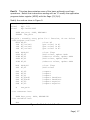
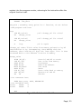
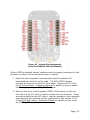
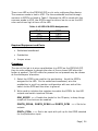
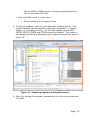
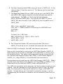
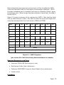
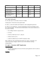
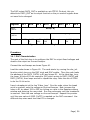
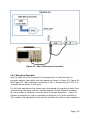
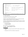
There is an LED on the FRDM-KL25Z is a tri-color red/green/blue device. The common anode is tied to VDD. The three cathodes are tied through resistors to GPIO’s as listed in Table 1. Because the LED is wired with the common anode to VDD, the GPIO’s must be driven low to run on the LED color and driven high to turn off the LED. Table 1- KL25Z LED GPIO Assignments LED Color RED GREEN BLUE GPIO PTB18 PTB19 PTD1 Required Equipment and Parts Solderless breadboard Pushbutton Jumper wires Procedure The aim of this lab is to wire a pushbutton to a GPIO on the FRDM-KL25Z, then to write software to change the color of the on-board LED when the button is pushed. The LED colors for pressed vs not pressed may be chosen at the developers’ discretion. 1. Select the GPIO to be used for the pushbutton. Avoid the GPIO’s assigned to the LED. On the solderless breadboard, wire the pushbutton in a pull-up resistor configuration with one side of the switch to the GPIO and the other to ground. 2. Write code to initialize the registers to enable the GPIO’s for the LED outputs and switch inputs as follows: SIM_SCGC5 <<< Enable the clocks for the IO ports, to keep things simple all the clock can be enabled PORTB_PCR18, PORTB_PCR19 and PORTD_PCR1 <<< Set to be outputs PORTx_PCRn <<< Set to be input with pull-up for the GPIO selected for the pushbutton input Page | 24