1
MC56F8006/MC56F8002 Reference Manual
16-Bit Digital Signal
Controllers (DSC)
MC56F8006RM
Rev. 2
11/2011
freescale.com
Freescale™ and the Freescale logo are trademarks of Freescale Semiconductor, Inc.
© Freescale Semiconductor, Inc., 2009–2011. All rights reserved.
Chapter 1
Device Overview
1.1
1.2
1.3
1.4
1.5
1.6
1.7
The MC56F8006/MC56F8002 Series . . . . . . . . . . . . . . . . . . . . . . . . . . . . . . . . . . . . . . 1-1
1.1.1 Introduction . . . . . . . . . . . . . . . . . . . . . . . . . . . . . . . . . . . . . . . . . . . . . . . . . . . . 1-1
1.1.2 MC56F8006/MC56F8002 Series Device Comparison . . . . . . . . . . . . . . . . . . . 1-2
MC56F8006/MC56F8002 Series Block Diagram . . . . . . . . . . . . . . . . . . . . . . . . . . . . . . 1-3
High Performance Core . . . . . . . . . . . . . . . . . . . . . . . . . . . . . . . . . . . . . . . . . . . . . . . . . 1-6
Operation Range . . . . . . . . . . . . . . . . . . . . . . . . . . . . . . . . . . . . . . . . . . . . . . . . . . . . . . 1-6
Memory Configuration . . . . . . . . . . . . . . . . . . . . . . . . . . . . . . . . . . . . . . . . . . . . . . . . . . 1-6
Module Configuration . . . . . . . . . . . . . . . . . . . . . . . . . . . . . . . . . . . . . . . . . . . . . . . . . . . 1-6
System Clock Generation and Distribution . . . . . . . . . . . . . . . . . . . . . . . . . . . . . . . . . 1-10
1.7.1 Clock Generation . . . . . . . . . . . . . . . . . . . . . . . . . . . . . . . . . . . . . . . . . . . . . . 1-10
1.7.2 Clock Distribution . . . . . . . . . . . . . . . . . . . . . . . . . . . . . . . . . . . . . . . . . . . . . . 1-10
1.7.3 Communication Between Peripherals . . . . . . . . . . . . . . . . . . . . . . . . . . . . . . . 1-11
Chapter 2
Analog-to-Digital Converter (ADC)
2.1
2.2
2.3
2.4
2.5
2.6
Introduction . . . . . . . . . . . . . . . . . . . . . . . . . . . . . . . . . . . . . . . . . . . . . . . . . . . . . . . . . . 2-1
2.1.1 Features . . . . . . . . . . . . . . . . . . . . . . . . . . . . . . . . . . . . . . . . . . . . . . . . . . . . . . 2-1
2.1.2 Related Material . . . . . . . . . . . . . . . . . . . . . . . . . . . . . . . . . . . . . . . . . . . . . . . . 2-1
2.1.3 Block Diagram . . . . . . . . . . . . . . . . . . . . . . . . . . . . . . . . . . . . . . . . . . . . . . . . . 2-2
External Signal Description . . . . . . . . . . . . . . . . . . . . . . . . . . . . . . . . . . . . . . . . . . . . . . 2-2
2.2.1 Analog Channel Inputs (ADn) . . . . . . . . . . . . . . . . . . . . . . . . . . . . . . . . . . . . . . 2-2
Register Definition . . . . . . . . . . . . . . . . . . . . . . . . . . . . . . . . . . . . . . . . . . . . . . . . . . . . . 2-3
2.3.1 Status and Control Register 1A and 1B (ADCn_ADCSC1A and ADCn_ADCSC1B)
2-3
2.3.2 Status and Control Register 2 (ADCn_ADCSC2) . . . . . . . . . . . . . . . . . . . . . . . 2-5
2.3.3 Data Result Registers A and B (ADCn_ADCRA and ADCn_ADCRB) . . . . . . . 2-6
2.3.4 Configuration Register (ADCn_ADCCFG) . . . . . . . . . . . . . . . . . . . . . . . . . . . . 2-6
Functional Description . . . . . . . . . . . . . . . . . . . . . . . . . . . . . . . . . . . . . . . . . . . . . . . . . . 2-8
2.4.1 Clock Select and Divide Control . . . . . . . . . . . . . . . . . . . . . . . . . . . . . . . . . . . . 2-8
2.4.2 Hardware Trigger . . . . . . . . . . . . . . . . . . . . . . . . . . . . . . . . . . . . . . . . . . . . . . . 2-8
2.4.3 Conversion Control . . . . . . . . . . . . . . . . . . . . . . . . . . . . . . . . . . . . . . . . . . . . . . 2-9
2.4.4 Temperature Sensor . . . . . . . . . . . . . . . . . . . . . . . . . . . . . . . . . . . . . . . . . . . . 2-11
2.4.5 DSC Core Wait Mode Operation . . . . . . . . . . . . . . . . . . . . . . . . . . . . . . . . . . . 2-12
2.4.6 DSC Core Stop Mode Operation . . . . . . . . . . . . . . . . . . . . . . . . . . . . . . . . . . 2-12
2.4.7 DSC Partial Power Down Mode Operation . . . . . . . . . . . . . . . . . . . . . . . . . . . 2-13
Initialization Information . . . . . . . . . . . . . . . . . . . . . . . . . . . . . . . . . . . . . . . . . . . . . . . . 2-13
2.5.1 ADC Module Initialization Example . . . . . . . . . . . . . . . . . . . . . . . . . . . . . . . . . 2-13
Application Information . . . . . . . . . . . . . . . . . . . . . . . . . . . . . . . . . . . . . . . . . . . . . . . . 2-15
2.6.1 External Pins and Routing . . . . . . . . . . . . . . . . . . . . . . . . . . . . . . . . . . . . . . . 2-15
2.6.2 Sources of Error . . . . . . . . . . . . . . . . . . . . . . . . . . . . . . . . . . . . . . . . . . . . . . . 2-16
Freescale Semiconductor
iii
Chapter 3
Programmable Gain Amplifier (PGA)
3.1
3.2
3.3
3.4
3.5
3.6
3.7
3.8
3.9
3.10
3.11
3.12
3.13
3.14
3.15
Introduction . . . . . . . . . . . . . . . . . . . . . . . . . . . . . . . . . . . . . . . . . . . . . . . . . . . . . . . . . . 3-1
3.1.1 Overview . . . . . . . . . . . . . . . . . . . . . . . . . . . . . . . . . . . . . . . . . . . . . . . . . . . . . . 3-1
Definitions . . . . . . . . . . . . . . . . . . . . . . . . . . . . . . . . . . . . . . . . . . . . . . . . . . . . . . . . . . . 3-2
Transfer Function . . . . . . . . . . . . . . . . . . . . . . . . . . . . . . . . . . . . . . . . . . . . . . . . . . . . . . 3-2
Options for On-Chip Analog Conversions . . . . . . . . . . . . . . . . . . . . . . . . . . . . . . . . . . . 3-2
PGA Prerequisites . . . . . . . . . . . . . . . . . . . . . . . . . . . . . . . . . . . . . . . . . . . . . . . . . . . . . 3-3
Analog Block Diagram . . . . . . . . . . . . . . . . . . . . . . . . . . . . . . . . . . . . . . . . . . . . . . . . . . 3-3
Dual PGA Options . . . . . . . . . . . . . . . . . . . . . . . . . . . . . . . . . . . . . . . . . . . . . . . . . . . . . 3-5
PGA Clocking . . . . . . . . . . . . . . . . . . . . . . . . . . . . . . . . . . . . . . . . . . . . . . . . . . . . . . . . 3-5
Effects on ADC Latency . . . . . . . . . . . . . . . . . . . . . . . . . . . . . . . . . . . . . . . . . . . . . . . . . 3-8
ADC Triggers . . . . . . . . . . . . . . . . . . . . . . . . . . . . . . . . . . . . . . . . . . . . . . . . . . . . . . . . . 3-9
Modes of Operation . . . . . . . . . . . . . . . . . . . . . . . . . . . . . . . . . . . . . . . . . . . . . . . . . . . 3-11
3.11.1 PGA Power Down . . . . . . . . . . . . . . . . . . . . . . . . . . . . . . . . . . . . . . . . . . . . . . 3-12
3.11.2 PGA Startup . . . . . . . . . . . . . . . . . . . . . . . . . . . . . . . . . . . . . . . . . . . . . . . . . . 3-12
3.11.3 PGA Calibration . . . . . . . . . . . . . . . . . . . . . . . . . . . . . . . . . . . . . . . . . . . . . . . 3-12
3.11.4 PGA Mission Mode . . . . . . . . . . . . . . . . . . . . . . . . . . . . . . . . . . . . . . . . . . . . . 3-14
Operation in Various Chip Operating Modes . . . . . . . . . . . . . . . . . . . . . . . . . . . . . . . . 3-15
3.12.1 Power Modes . . . . . . . . . . . . . . . . . . . . . . . . . . . . . . . . . . . . . . . . . . . . . . . . . 3-15
3.12.2 Operation During Run, Wait, and Stop . . . . . . . . . . . . . . . . . . . . . . . . . . . . . . 3-16
3.12.3 Operation During LPRun, LPWait, and LPStop . . . . . . . . . . . . . . . . . . . . . . . 3-16
3.12.4 Operation During Partial Power Down (PPD) . . . . . . . . . . . . . . . . . . . . . . . . . 3-16
Interrupts . . . . . . . . . . . . . . . . . . . . . . . . . . . . . . . . . . . . . . . . . . . . . . . . . . . . . . . . . . . 3-16
Reset Considerations . . . . . . . . . . . . . . . . . . . . . . . . . . . . . . . . . . . . . . . . . . . . . . . . . 3-16
Register Definitions . . . . . . . . . . . . . . . . . . . . . . . . . . . . . . . . . . . . . . . . . . . . . . . . . . . 3-16
3.15.1 Control Register 0 (PGAn_CNTL0) . . . . . . . . . . . . . . . . . . . . . . . . . . . . . . . . 3-17
3.15.2 Control Register 1 (PGAn_CNTL1) . . . . . . . . . . . . . . . . . . . . . . . . . . . . . . . . 3-18
3.15.3 Control Register 2 (PGAn_CNTL2) . . . . . . . . . . . . . . . . . . . . . . . . . . . . . . . . 3-19
3.15.4 Status Register (PGAn_STS) . . . . . . . . . . . . . . . . . . . . . . . . . . . . . . . . . . . . . 3-20
Chapter 4
High Speed Comparator (HSCMP)
4.1
4.2
4.3
4.4
4.5
iv
Introduction . . . . . . . . . . . . . . . . . . . . . . . . . . . . . . . . . . . . . . . . . . . . . . . . . . . . . . . . . . 4-1
Features . . . . . . . . . . . . . . . . . . . . . . . . . . . . . . . . . . . . . . . . . . . . . . . . . . . . . . . . . . . . . 4-1
Block Diagram . . . . . . . . . . . . . . . . . . . . . . . . . . . . . . . . . . . . . . . . . . . . . . . . . . . . . . . . 4-1
Pin Descriptions . . . . . . . . . . . . . . . . . . . . . . . . . . . . . . . . . . . . . . . . . . . . . . . . . . . . . . . 4-3
4.4.1 External Pins . . . . . . . . . . . . . . . . . . . . . . . . . . . . . . . . . . . . . . . . . . . . . . . . . . 4-3
Functional Description . . . . . . . . . . . . . . . . . . . . . . . . . . . . . . . . . . . . . . . . . . . . . . . . . . 4-3
4.5.1 HSCMP Functional Modes . . . . . . . . . . . . . . . . . . . . . . . . . . . . . . . . . . . . . . . . 4-4
4.5.2 Power Modes . . . . . . . . . . . . . . . . . . . . . . . . . . . . . . . . . . . . . . . . . . . . . . . . . 4-13
4.5.3 Hysteresis . . . . . . . . . . . . . . . . . . . . . . . . . . . . . . . . . . . . . . . . . . . . . . . . . . . . 4-14
Freescale Semiconductor
4.6
4.7
4.5.4 Startup and Operation . . . . . . . . . . . . . . . . . . . . . . . . . . . . . . . . . . . . . . . . . .
4.5.5 Low Pass Filter . . . . . . . . . . . . . . . . . . . . . . . . . . . . . . . . . . . . . . . . . . . . . . . .
Interrupts . . . . . . . . . . . . . . . . . . . . . . . . . . . . . . . . . . . . . . . . . . . . . . . . . . . . . . . . . . .
Memory Map and Register Definition . . . . . . . . . . . . . . . . . . . . . . . . . . . . . . . . . . . . .
4.7.1 Control Register 0 (CMPn_CR0) . . . . . . . . . . . . . . . . . . . . . . . . . . . . . . . . . .
4.7.2 Control Register 1 (CMPn_CR1) . . . . . . . . . . . . . . . . . . . . . . . . . . . . . . . . . .
4.7.3 Filter Period Register (CMPn_FPR) . . . . . . . . . . . . . . . . . . . . . . . . . . . . . . . .
4.7.4 Status and Control Register (CMPn_SCR) . . . . . . . . . . . . . . . . . . . . . . . . . . .
4-15
4-15
4-17
4-17
4-18
4-18
4-20
4-20
Chapter 5
Programmable Delay Block (PDB)
5.1
5.2
5.3
5.4
Introduction . . . . . . . . . . . . . . . . . . . . . . . . . . . . . . . . . . . . . . . . . . . . . . . . . . . . . . . . . .
5.1.1 Overview . . . . . . . . . . . . . . . . . . . . . . . . . . . . . . . . . . . . . . . . . . . . . . . . . . . . . .
5.1.2 Features . . . . . . . . . . . . . . . . . . . . . . . . . . . . . . . . . . . . . . . . . . . . . . . . . . . . . .
5.1.3 Modes of Operation . . . . . . . . . . . . . . . . . . . . . . . . . . . . . . . . . . . . . . . . . . . . .
5.1.4 Block Diagram . . . . . . . . . . . . . . . . . . . . . . . . . . . . . . . . . . . . . . . . . . . . . . . . .
Memory Map and Registers . . . . . . . . . . . . . . . . . . . . . . . . . . . . . . . . . . . . . . . . . . . . .
5.2.1 Memory Map . . . . . . . . . . . . . . . . . . . . . . . . . . . . . . . . . . . . . . . . . . . . . . . . . . .
5.2.2 Register Descriptions . . . . . . . . . . . . . . . . . . . . . . . . . . . . . . . . . . . . . . . . . . . .
5.2.3 Functional Description . . . . . . . . . . . . . . . . . . . . . . . . . . . . . . . . . . . . . . . . . . .
Resets . . . . . . . . . . . . . . . . . . . . . . . . . . . . . . . . . . . . . . . . . . . . . . . . . . . . . . . . . . . . . .
Interrupts . . . . . . . . . . . . . . . . . . . . . . . . . . . . . . . . . . . . . . . . . . . . . . . . . . . . . . . . . . . .
5-1
5-1
5-1
5-1
5-2
5-5
5-5
5-5
5-7
5-8
5-8
Chapter 6
Dual Timer (DTMR)
6.1
6.2
6.3
6.4
6.5
Introduction . . . . . . . . . . . . . . . . . . . . . . . . . . . . . . . . . . . . . . . . . . . . . . . . . . . . . . . . . . 6-1
6.1.1 Overview . . . . . . . . . . . . . . . . . . . . . . . . . . . . . . . . . . . . . . . . . . . . . . . . . . . . . . 6-1
6.1.2 Features . . . . . . . . . . . . . . . . . . . . . . . . . . . . . . . . . . . . . . . . . . . . . . . . . . . . . . 6-1
6.1.3 Mode of Operation . . . . . . . . . . . . . . . . . . . . . . . . . . . . . . . . . . . . . . . . . . . . . . 6-2
6.1.4 Block Diagram . . . . . . . . . . . . . . . . . . . . . . . . . . . . . . . . . . . . . . . . . . . . . . . . . 6-2
Memory Map and Registers . . . . . . . . . . . . . . . . . . . . . . . . . . . . . . . . . . . . . . . . . . . . . 6-3
6.2.1 Overview . . . . . . . . . . . . . . . . . . . . . . . . . . . . . . . . . . . . . . . . . . . . . . . . . . . . . . 6-3
6.2.2 Module Memory Map . . . . . . . . . . . . . . . . . . . . . . . . . . . . . . . . . . . . . . . . . . . . 6-3
6.2.3 Register Descriptions . . . . . . . . . . . . . . . . . . . . . . . . . . . . . . . . . . . . . . . . . . . . 6-4
Functional Description . . . . . . . . . . . . . . . . . . . . . . . . . . . . . . . . . . . . . . . . . . . . . . . . . 6-14
6.3.1 General . . . . . . . . . . . . . . . . . . . . . . . . . . . . . . . . . . . . . . . . . . . . . . . . . . . . . . 6-14
6.3.2 Functional Modes . . . . . . . . . . . . . . . . . . . . . . . . . . . . . . . . . . . . . . . . . . . . . . 6-15
Resets . . . . . . . . . . . . . . . . . . . . . . . . . . . . . . . . . . . . . . . . . . . . . . . . . . . . . . . . . . . . . 6-29
6.4.1 General . . . . . . . . . . . . . . . . . . . . . . . . . . . . . . . . . . . . . . . . . . . . . . . . . . . . . . 6-29
Interrupts . . . . . . . . . . . . . . . . . . . . . . . . . . . . . . . . . . . . . . . . . . . . . . . . . . . . . . . . . . . 6-29
Freescale Semiconductor
v
6.5.1 General . . . . . . . . . . . . . . . . . . . . . . . . . . . . . . . . . . . . . . . . . . . . . . . . . . . . . . 6-29
6.5.2 Description of Interrupt Operation . . . . . . . . . . . . . . . . . . . . . . . . . . . . . . . . . 6-30
Chapter 7
Pulse Width Modulator (PWM)
7.1
7.2
7.3
7.4
vi
Introduction . . . . . . . . . . . . . . . . . . . . . . . . . . . . . . . . . . . . . . . . . . . . . . . . . . . . . . . . . . 7-1
7.1.1 Overview . . . . . . . . . . . . . . . . . . . . . . . . . . . . . . . . . . . . . . . . . . . . . . . . . . . . . . 7-1
7.1.2 Features . . . . . . . . . . . . . . . . . . . . . . . . . . . . . . . . . . . . . . . . . . . . . . . . . . . . . . 7-1
7.1.3 Modes of Operation . . . . . . . . . . . . . . . . . . . . . . . . . . . . . . . . . . . . . . . . . . . . . 7-2
7.1.4 Block Diagrams . . . . . . . . . . . . . . . . . . . . . . . . . . . . . . . . . . . . . . . . . . . . . . . . . 7-3
Functional Description . . . . . . . . . . . . . . . . . . . . . . . . . . . . . . . . . . . . . . . . . . . . . . . . . . 7-4
7.2.1 Prescaler . . . . . . . . . . . . . . . . . . . . . . . . . . . . . . . . . . . . . . . . . . . . . . . . . . . . . . 7-4
7.2.2 Generator . . . . . . . . . . . . . . . . . . . . . . . . . . . . . . . . . . . . . . . . . . . . . . . . . . . . . 7-4
7.2.3 Independent or Complementary Channel Operation . . . . . . . . . . . . . . . . . . . . 7-8
7.2.4 Deadtime Generators . . . . . . . . . . . . . . . . . . . . . . . . . . . . . . . . . . . . . . . . . . . . 7-9
7.2.5 Asymmetric PWM Output . . . . . . . . . . . . . . . . . . . . . . . . . . . . . . . . . . . . . . . . 7-14
7.2.6 Variable Edge Placement PWM Output . . . . . . . . . . . . . . . . . . . . . . . . . . . . . 7-15
7.2.7 PWM Output Polarity . . . . . . . . . . . . . . . . . . . . . . . . . . . . . . . . . . . . . . . . . . . 7-16
7.2.8 Software Output Control . . . . . . . . . . . . . . . . . . . . . . . . . . . . . . . . . . . . . . . . . 7-17
7.2.9 Generator Loading . . . . . . . . . . . . . . . . . . . . . . . . . . . . . . . . . . . . . . . . . . . . . 7-19
7.2.10 Fault Protection . . . . . . . . . . . . . . . . . . . . . . . . . . . . . . . . . . . . . . . . . . . . . . . . 7-23
7.2.11 External Synchronization of PWM Counting (EXT_SYNC) . . . . . . . . . . . . . . 7-26
Signal Descriptions . . . . . . . . . . . . . . . . . . . . . . . . . . . . . . . . . . . . . . . . . . . . . . . . . . . 7-26
7.3.1 PWM0–PWM5 Pins . . . . . . . . . . . . . . . . . . . . . . . . . . . . . . . . . . . . . . . . . . . . 7-26
7.3.2 FAULT0–FAULT3 Pins . . . . . . . . . . . . . . . . . . . . . . . . . . . . . . . . . . . . . . . . . . . 7-26
7.3.3 Inter-module Connection Signals . . . . . . . . . . . . . . . . . . . . . . . . . . . . . . . . . . 7-27
Memory Map and Registers . . . . . . . . . . . . . . . . . . . . . . . . . . . . . . . . . . . . . . . . . . . . 7-27
7.4.1 Module Memory Map . . . . . . . . . . . . . . . . . . . . . . . . . . . . . . . . . . . . . . . . . . . 7-27
7.4.2 Register Descriptions . . . . . . . . . . . . . . . . . . . . . . . . . . . . . . . . . . . . . . . . . . . 7-28
7.4.3 PWM Control Register (PWM_CTRL) . . . . . . . . . . . . . . . . . . . . . . . . . . . . . . 7-28
7.4.4 PWM Fault Control Register (PWM_FCTRL) . . . . . . . . . . . . . . . . . . . . . . . . . 7-30
7.4.5 PWM Fault Status Acknowledge Register (PWM_FLTACK) . . . . . . . . . . . . . . 7-31
7.4.6 PWM Output Control Register (PWM_OUT) . . . . . . . . . . . . . . . . . . . . . . . . . 7-32
7.4.7 PWM Counter Modulo Register (PWM_CMOD) . . . . . . . . . . . . . . . . . . . . . . . 7-33
7.4.8 PWM Value Registers (PWM_VAL0–5) . . . . . . . . . . . . . . . . . . . . . . . . . . . . . 7-34
7.4.9 PWM Deadtime Registers (PWM_DTIM0, PWM_DTIM1) . . . . . . . . . . . . . . . 7-34
7.4.10 PWM Disable Mapping Registers (PWM_DMAP1-2) . . . . . . . . . . . . . . . . . . . 7-35
7.4.11 PWM Configure Register (PWM_CNFG) . . . . . . . . . . . . . . . . . . . . . . . . . . . . 7-36
7.4.12 PWM Channel Control Register (PWM_CCTRL) . . . . . . . . . . . . . . . . . . . . . . 7-37
7.4.13 PWM Port Register (PWM_PORT) . . . . . . . . . . . . . . . . . . . . . . . . . . . . . . . . . 7-39
7.4.14 PWM Internal Correction Control Register (PWM_ICCTRL) . . . . . . . . . . . . . 7-40
7.4.15 PWM Source Control Register (PWM_SCTRL) . . . . . . . . . . . . . . . . . . . . . . . 7-41
7.4.16 PWM Synchronization Window Register (PWM_SYNC) . . . . . . . . . . . . . . . . 7-42
Freescale Semiconductor
7.5
7.6
7.7
7.4.17 Fault Filter Registers (PWM_FFILT0, PWM_FFILT1, PWM_FFILT2, PWM_FFILT3)
7-43
Resets . . . . . . . . . . . . . . . . . . . . . . . . . . . . . . . . . . . . . . . . . . . . . . . . . . . . . . . . . . . . . 7-44
Clocks . . . . . . . . . . . . . . . . . . . . . . . . . . . . . . . . . . . . . . . . . . . . . . . . . . . . . . . . . . . . . 7-44
Interrupts . . . . . . . . . . . . . . . . . . . . . . . . . . . . . . . . . . . . . . . . . . . . . . . . . . . . . . . . . . . 7-45
Chapter 8
General-Purpose Input/Output (GPIO)
8.1
8.2
8.3
8.4
Overview . . . . . . . . . . . . . . . . . . . . . . . . . . . . . . . . . . . . . . . . . . . . . . . . . . . . . . . . . . . .
8.1.1 Features . . . . . . . . . . . . . . . . . . . . . . . . . . . . . . . . . . . . . . . . . . . . . . . . . . . . . .
8.1.2 Modes of Operation . . . . . . . . . . . . . . . . . . . . . . . . . . . . . . . . . . . . . . . . . . . . .
8.1.3 Block Diagram . . . . . . . . . . . . . . . . . . . . . . . . . . . . . . . . . . . . . . . . . . . . . . . . .
GPIO Interrupts . . . . . . . . . . . . . . . . . . . . . . . . . . . . . . . . . . . . . . . . . . . . . . . . . . . . . . .
Clocks and Resets . . . . . . . . . . . . . . . . . . . . . . . . . . . . . . . . . . . . . . . . . . . . . . . . . . . . .
Memory Map and Registers . . . . . . . . . . . . . . . . . . . . . . . . . . . . . . . . . . . . . . . . . . . . .
8.4.1 Module Memory Map . . . . . . . . . . . . . . . . . . . . . . . . . . . . . . . . . . . . . . . . . . . .
8.4.2 Register Descriptions . . . . . . . . . . . . . . . . . . . . . . . . . . . . . . . . . . . . . . . . . . . .
8-1
8-1
8-2
8-2
8-4
8-5
8-5
8-5
8-5
Chapter 9
Inter-Integrated Circuit (I2C)
9.1
9.2
9.3
9.4
Introduction . . . . . . . . . . . . . . . . . . . . . . . . . . . . . . . . . . . . . . . . . . . . . . . . . . . . . . . . . . 9-1
9.1.1 Features . . . . . . . . . . . . . . . . . . . . . . . . . . . . . . . . . . . . . . . . . . . . . . . . . . . . . . 9-1
9.1.2 Modes of Operation . . . . . . . . . . . . . . . . . . . . . . . . . . . . . . . . . . . . . . . . . . . . . 9-1
9.1.3 Block Diagram . . . . . . . . . . . . . . . . . . . . . . . . . . . . . . . . . . . . . . . . . . . . . . . . . 9-2
External Signal Description . . . . . . . . . . . . . . . . . . . . . . . . . . . . . . . . . . . . . . . . . . . . . . 9-2
9.2.1 SCL — Serial Clock Line . . . . . . . . . . . . . . . . . . . . . . . . . . . . . . . . . . . . . . . . . 9-2
9.2.2 SDA — Serial Data Line . . . . . . . . . . . . . . . . . . . . . . . . . . . . . . . . . . . . . . . . . . 9-2
Register Definition . . . . . . . . . . . . . . . . . . . . . . . . . . . . . . . . . . . . . . . . . . . . . . . . . . . . . 9-3
9.3.1 Module Memory Map . . . . . . . . . . . . . . . . . . . . . . . . . . . . . . . . . . . . . . . . . . . . 9-3
9.3.2 IIC Address Register 1 (I2C_ADDR) . . . . . . . . . . . . . . . . . . . . . . . . . . . . . . . . 9-4
9.3.3 IIC Frequency Divider Register (I2C_FREQDIV) . . . . . . . . . . . . . . . . . . . . . . . 9-4
9.3.4 IIC Control Register (I2C_CR1) . . . . . . . . . . . . . . . . . . . . . . . . . . . . . . . . . . . . 9-6
9.3.5 IIC Status Register (I2C_SR) . . . . . . . . . . . . . . . . . . . . . . . . . . . . . . . . . . . . . . 9-7
9.3.6 IIC Data I/O Register (I2C_DATA) . . . . . . . . . . . . . . . . . . . . . . . . . . . . . . . . . . . 9-8
9.3.7 IIC Control Register 2 (I2C_CR2) . . . . . . . . . . . . . . . . . . . . . . . . . . . . . . . . . . . 9-9
9.3.8 IIC SMBus Control and Status Register (I2C_SMB_CSR) . . . . . . . . . . . . . . . 9-10
9.3.9 IIC Address Register 2 (I2C_ADDR2) . . . . . . . . . . . . . . . . . . . . . . . . . . . . . . 9-11
9.3.10 IIC SCL Low Time Out Register High (I2C_SLT1) . . . . . . . . . . . . . . . . . . . . . 9-11
9.3.11 IIC SCL Low Time Out register Low (I2C_SLT2) . . . . . . . . . . . . . . . . . . . . . . 9-11
Functional Description . . . . . . . . . . . . . . . . . . . . . . . . . . . . . . . . . . . . . . . . . . . . . . . . . 9-12
9.4.1 IIC Protocol . . . . . . . . . . . . . . . . . . . . . . . . . . . . . . . . . . . . . . . . . . . . . . . . . . . 9-12
9.4.2 10-bit Address . . . . . . . . . . . . . . . . . . . . . . . . . . . . . . . . . . . . . . . . . . . . . . . . . 9-15
Freescale Semiconductor
vii
9.5
9.6
9.7
9.4.3 Address Matching . . . . . . . . . . . . . . . . . . . . . . . . . . . . . . . . . . . . . . . . . . . . . .
9.4.4 System Management Bus Specification . . . . . . . . . . . . . . . . . . . . . . . . . . . . .
Resets . . . . . . . . . . . . . . . . . . . . . . . . . . . . . . . . . . . . . . . . . . . . . . . . . . . . . . . . . . . . .
Interrupts . . . . . . . . . . . . . . . . . . . . . . . . . . . . . . . . . . . . . . . . . . . . . . . . . . . . . . . . . . .
9.6.1 Byte Transfer Interrupt . . . . . . . . . . . . . . . . . . . . . . . . . . . . . . . . . . . . . . . . . .
9.6.2 Address Detect Interrupt . . . . . . . . . . . . . . . . . . . . . . . . . . . . . . . . . . . . . . . . .
9.6.3 Arbitration Lost Interrupt . . . . . . . . . . . . . . . . . . . . . . . . . . . . . . . . . . . . . . . . .
9.6.4 Timeouts Interrupt in SMbus . . . . . . . . . . . . . . . . . . . . . . . . . . . . . . . . . . . . . .
Initialization/Application Information . . . . . . . . . . . . . . . . . . . . . . . . . . . . . . . . . . . . . .
9.7.1 Module Initialization (Slave) . . . . . . . . . . . . . . . . . . . . . . . . . . . . . . . . . . . . . .
9.7.2 Module Initialization (Master) . . . . . . . . . . . . . . . . . . . . . . . . . . . . . . . . . . . . .
9.7.3 Module Use . . . . . . . . . . . . . . . . . . . . . . . . . . . . . . . . . . . . . . . . . . . . . . . . . . .
9-16
9-16
9-18
9-18
9-19
9-19
9-19
9-19
9-19
9-19
9-20
9-20
Chapter 10
Serial Communications Interface (SCI)
10.1
10.2
10.3
10.4
10.5
10.6
10.7
10.8
10.9
Overview . . . . . . . . . . . . . . . . . . . . . . . . . . . . . . . . . . . . . . . . . . . . . . . . . . . . . . . . . . . 10-1
Features . . . . . . . . . . . . . . . . . . . . . . . . . . . . . . . . . . . . . . . . . . . . . . . . . . . . . . . . . . . . 10-1
Block Diagram . . . . . . . . . . . . . . . . . . . . . . . . . . . . . . . . . . . . . . . . . . . . . . . . . . . . . . . 10-1
Signal Descriptions . . . . . . . . . . . . . . . . . . . . . . . . . . . . . . . . . . . . . . . . . . . . . . . . . . . 10-2
10.4.1 Overview . . . . . . . . . . . . . . . . . . . . . . . . . . . . . . . . . . . . . . . . . . . . . . . . . . . . . 10-2
10.4.2 External Pin Descriptions . . . . . . . . . . . . . . . . . . . . . . . . . . . . . . . . . . . . . . . . 10-2
Memory Map and Registers . . . . . . . . . . . . . . . . . . . . . . . . . . . . . . . . . . . . . . . . . . . . 10-3
10.5.1 Overview . . . . . . . . . . . . . . . . . . . . . . . . . . . . . . . . . . . . . . . . . . . . . . . . . . . . . 10-3
10.5.2 Module Memory Map . . . . . . . . . . . . . . . . . . . . . . . . . . . . . . . . . . . . . . . . . . . 10-3
10.5.3 Register Descriptions . . . . . . . . . . . . . . . . . . . . . . . . . . . . . . . . . . . . . . . . . . . 10-3
Functional Description . . . . . . . . . . . . . . . . . . . . . . . . . . . . . . . . . . . . . . . . . . . . . . . . . 10-9
10.6.1 General . . . . . . . . . . . . . . . . . . . . . . . . . . . . . . . . . . . . . . . . . . . . . . . . . . . . . . 10-9
Resets . . . . . . . . . . . . . . . . . . . . . . . . . . . . . . . . . . . . . . . . . . . . . . . . . . . . . . . . . . . . 10-25
Clocks . . . . . . . . . . . . . . . . . . . . . . . . . . . . . . . . . . . . . . . . . . . . . . . . . . . . . . . . . . . . 10-25
Interrupts . . . . . . . . . . . . . . . . . . . . . . . . . . . . . . . . . . . . . . . . . . . . . . . . . . . . . . . . . . 10-25
10.9.1 General . . . . . . . . . . . . . . . . . . . . . . . . . . . . . . . . . . . . . . . . . . . . . . . . . . . . . 10-25
10.9.2 Description of Interrupt Operation . . . . . . . . . . . . . . . . . . . . . . . . . . . . . . . . 10-26
Chapter 11
Serial Peripheral Interface (SPI)
11.1 Introduction . . . . . . . . . . . . . . . . . . . . . . . . . . . . . . . . . . . . . . . . . . . . . . . . . . . . . . . . .
11.1.1 Overview . . . . . . . . . . . . . . . . . . . . . . . . . . . . . . . . . . . . . . . . . . . . . . . . . . . . .
11.1.2 Block Diagram . . . . . . . . . . . . . . . . . . . . . . . . . . . . . . . . . . . . . . . . . . . . . . . .
11.2 Signal Descriptions . . . . . . . . . . . . . . . . . . . . . . . . . . . . . . . . . . . . . . . . . . . . . . . . . . .
11.2.1 External I/O Signals . . . . . . . . . . . . . . . . . . . . . . . . . . . . . . . . . . . . . . . . . . . .
11.2.2 MISO (Master In/Slave Out) . . . . . . . . . . . . . . . . . . . . . . . . . . . . . . . . . . . . . .
11.3 Memory Map and Registers . . . . . . . . . . . . . . . . . . . . . . . . . . . . . . . . . . . . . . . . . . . .
viii
11-1
11-1
11-2
11-2
11-2
11-3
11-4
Freescale Semiconductor
11.3.1 Module Memory Map . . . . . . . . . . . . . . . . . . . . . . . . . . . . . . . . . . . . . . . . . . . 11-4
11.3.2 Register Descriptions . . . . . . . . . . . . . . . . . . . . . . . . . . . . . . . . . . . . . . . . . . . 11-5
11.4 Functional Description . . . . . . . . . . . . . . . . . . . . . . . . . . . . . . . . . . . . . . . . . . . . . . . . 11-11
11.4.1 Operating Modes . . . . . . . . . . . . . . . . . . . . . . . . . . . . . . . . . . . . . . . . . . . . . 11-11
11.4.2 Transaction Formats . . . . . . . . . . . . . . . . . . . . . . . . . . . . . . . . . . . . . . . . . . . 11-13
11.4.3 Transmission Data . . . . . . . . . . . . . . . . . . . . . . . . . . . . . . . . . . . . . . . . . . . . 11-18
11.4.4 Error Conditions . . . . . . . . . . . . . . . . . . . . . . . . . . . . . . . . . . . . . . . . . . . . . . 11-19
11.4.5 Resetting the SPI . . . . . . . . . . . . . . . . . . . . . . . . . . . . . . . . . . . . . . . . . . . . . 11-23
11.5 Interrupts . . . . . . . . . . . . . . . . . . . . . . . . . . . . . . . . . . . . . . . . . . . . . . . . . . . . . . . . . . 11-23
Chapter 12
Interrupt Controller (WINTC)
12.1 Introduction . . . . . . . . . . . . . . . . . . . . . . . . . . . . . . . . . . . . . . . . . . . . . . . . . . . . . . . . . 12-1
12.1.1 Overview . . . . . . . . . . . . . . . . . . . . . . . . . . . . . . . . . . . . . . . . . . . . . . . . . . . . . 12-1
12.1.2 Features . . . . . . . . . . . . . . . . . . . . . . . . . . . . . . . . . . . . . . . . . . . . . . . . . . . . . 12-1
12.1.3 Modes of Operation . . . . . . . . . . . . . . . . . . . . . . . . . . . . . . . . . . . . . . . . . . . . 12-2
12.1.4 Block Diagram . . . . . . . . . . . . . . . . . . . . . . . . . . . . . . . . . . . . . . . . . . . . . . . . 12-2
12.2 Functional Description . . . . . . . . . . . . . . . . . . . . . . . . . . . . . . . . . . . . . . . . . . . . . . . . . 12-3
12.2.1 Discussion of the Interrupt Controller Block Diagram . . . . . . . . . . . . . . . . . . . 12-3
12.2.2 Overview . . . . . . . . . . . . . . . . . . . . . . . . . . . . . . . . . . . . . . . . . . . . . . . . . . . . . 12-4
12.2.3 Normal Interrupt Handling . . . . . . . . . . . . . . . . . . . . . . . . . . . . . . . . . . . . . . . 12-5
12.2.4 Interrupt Nesting . . . . . . . . . . . . . . . . . . . . . . . . . . . . . . . . . . . . . . . . . . . . . . . 12-5
12.2.5 Fast Interrupt Handling . . . . . . . . . . . . . . . . . . . . . . . . . . . . . . . . . . . . . . . . . . 12-5
12.3 Memory Map and Registers . . . . . . . . . . . . . . . . . . . . . . . . . . . . . . . . . . . . . . . . . . . . 12-6
12.3.1 Interrupt Vector Table . . . . . . . . . . . . . . . . . . . . . . . . . . . . . . . . . . . . . . . . . . . 12-6
12.3.2 Module Memory Map . . . . . . . . . . . . . . . . . . . . . . . . . . . . . . . . . . . . . . . . . . 12-10
12.3.3 Register Descriptions . . . . . . . . . . . . . . . . . . . . . . . . . . . . . . . . . . . . . . . . . . 12-11
12.4 Resets . . . . . . . . . . . . . . . . . . . . . . . . . . . . . . . . . . . . . . . . . . . . . . . . . . . . . . . . . . . . 12-13
Chapter 13
On-Chip Clock Synthesis (OCCS)
13.1 Introduction . . . . . . . . . . . . . . . . . . . . . . . . . . . . . . . . . . . . . . . . . . . . . . . . . . . . . . . . .
13.1.1 Overview . . . . . . . . . . . . . . . . . . . . . . . . . . . . . . . . . . . . . . . . . . . . . . . . . . . . .
13.1.2 Features . . . . . . . . . . . . . . . . . . . . . . . . . . . . . . . . . . . . . . . . . . . . . . . . . . . . .
13.2 Modes of Operation . . . . . . . . . . . . . . . . . . . . . . . . . . . . . . . . . . . . . . . . . . . . . . . . . . .
13.2.1 Internal Clock Source . . . . . . . . . . . . . . . . . . . . . . . . . . . . . . . . . . . . . . . . . . .
13.2.2 Crystal (or Ceramic Resonator) Oscillator . . . . . . . . . . . . . . . . . . . . . . . . . . .
13.2.3 External Clock Source — Crystal Oscillator Option . . . . . . . . . . . . . . . . . . . .
13.2.4 External Clock Source — GPIO . . . . . . . . . . . . . . . . . . . . . . . . . . . . . . . . . . .
13.3 Block Diagram . . . . . . . . . . . . . . . . . . . . . . . . . . . . . . . . . . . . . . . . . . . . . . . . . . . . . . .
13.4 Pin Descriptions . . . . . . . . . . . . . . . . . . . . . . . . . . . . . . . . . . . . . . . . . . . . . . . . . . . . . .
13.4.1 External Reference . . . . . . . . . . . . . . . . . . . . . . . . . . . . . . . . . . . . . . . . . . . . .
Freescale Semiconductor
13-1
13-1
13-1
13-2
13-2
13-3
13-4
13-5
13-6
13-7
13-7
ix
13.4.2 Oscillator Inputs (XTAL, EXTAL) . . . . . . . . . . . . . . . . . . . . . . . . . . . . . . . . . . . 13-7
13.4.3 CLKO . . . . . . . . . . . . . . . . . . . . . . . . . . . . . . . . . . . . . . . . . . . . . . . . . . . . . . . 13-7
13.5 Memory Map and Registers . . . . . . . . . . . . . . . . . . . . . . . . . . . . . . . . . . . . . . . . . . . . 13-7
13.5.1 Module Memory Map . . . . . . . . . . . . . . . . . . . . . . . . . . . . . . . . . . . . . . . . . . . 13-7
13.6 Register Descriptions . . . . . . . . . . . . . . . . . . . . . . . . . . . . . . . . . . . . . . . . . . . . . . . . . 13-8
13.6.1 PLL Control Register (OCCS_CTRL) . . . . . . . . . . . . . . . . . . . . . . . . . . . . . . . 13-8
13.6.2 PLL Divide-By Register (OCCS_DIVBY) . . . . . . . . . . . . . . . . . . . . . . . . . . . . 13-9
13.6.3 OCCS Status Register (OCCS_STAT) . . . . . . . . . . . . . . . . . . . . . . . . . . . . . 13-10
13.6.4 Oscillator Control Register (OCCS_OCTRL) . . . . . . . . . . . . . . . . . . . . . . . . 13-11
13.6.5 External Clock Check (OCCS_CLKCHKR and OCCS_CLKCHKT) . . . . . . . 13-13
13.6.6 Protection Register (OCCS_PROT) . . . . . . . . . . . . . . . . . . . . . . . . . . . . . . . 13-14
13.7 Functional Description . . . . . . . . . . . . . . . . . . . . . . . . . . . . . . . . . . . . . . . . . . . . . . . . 13-15
13.8 Relaxation Oscillator . . . . . . . . . . . . . . . . . . . . . . . . . . . . . . . . . . . . . . . . . . . . . . . . . 13-19
13.8.1 Trimming Frequency on the Internal Relaxation Oscillator . . . . . . . . . . . . . . 13-19
13.9 External Reference . . . . . . . . . . . . . . . . . . . . . . . . . . . . . . . . . . . . . . . . . . . . . . . . . . 13-19
13.10Crystal Oscillator . . . . . . . . . . . . . . . . . . . . . . . . . . . . . . . . . . . . . . . . . . . . . . . . . . . . 13-19
13.10.1Switching Clock Sources . . . . . . . . . . . . . . . . . . . . . . . . . . . . . . . . . . . . . . . 13-19
13.11Phase Locked Loop . . . . . . . . . . . . . . . . . . . . . . . . . . . . . . . . . . . . . . . . . . . . . . . . . . 13-20
13.11.1PLL Recommended Range of Operation . . . . . . . . . . . . . . . . . . . . . . . . . . 13-20
13.11.2PLL Lock Time Specification . . . . . . . . . . . . . . . . . . . . . . . . . . . . . . . . . . . . 13-20
13.12PLL Frequency Lock Detector Block . . . . . . . . . . . . . . . . . . . . . . . . . . . . . . . . . . . . . 13-21
13.13Loss of Reference Clock Detector . . . . . . . . . . . . . . . . . . . . . . . . . . . . . . . . . . . . . . . 13-22
13.14Clocks . . . . . . . . . . . . . . . . . . . . . . . . . . . . . . . . . . . . . . . . . . . . . . . . . . . . . . . . . . . . 13-22
13.15Interrupts . . . . . . . . . . . . . . . . . . . . . . . . . . . . . . . . . . . . . . . . . . . . . . . . . . . . . . . . . . 13-23
Chapter 14
System Integration Module (SIM)
14.1 Introduction . . . . . . . . . . . . . . . . . . . . . . . . . . . . . . . . . . . . . . . . . . . . . . . . . . . . . . . . . 14-1
14.1.1 Overview . . . . . . . . . . . . . . . . . . . . . . . . . . . . . . . . . . . . . . . . . . . . . . . . . . . . . 14-1
14.1.2 References . . . . . . . . . . . . . . . . . . . . . . . . . . . . . . . . . . . . . . . . . . . . . . . . . . . 14-1
14.1.3 Features . . . . . . . . . . . . . . . . . . . . . . . . . . . . . . . . . . . . . . . . . . . . . . . . . . . . . 14-1
14.1.4 Modes of Operation . . . . . . . . . . . . . . . . . . . . . . . . . . . . . . . . . . . . . . . . . . . . 14-3
14.2 Memory Map and Registers . . . . . . . . . . . . . . . . . . . . . . . . . . . . . . . . . . . . . . . . . . . . 14-4
14.2.1 Module Memory Map . . . . . . . . . . . . . . . . . . . . . . . . . . . . . . . . . . . . . . . . . . . 14-4
14.2.2 Register Descriptions . . . . . . . . . . . . . . . . . . . . . . . . . . . . . . . . . . . . . . . . . . . 14-4
14.3 Functional Descriptions . . . . . . . . . . . . . . . . . . . . . . . . . . . . . . . . . . . . . . . . . . . . . . . 14-25
14.3.1 Clock Generation Overview . . . . . . . . . . . . . . . . . . . . . . . . . . . . . . . . . . . . . 14-25
14.3.2 Power-Down Modes Overview . . . . . . . . . . . . . . . . . . . . . . . . . . . . . . . . . . . 14-25
14.3.3 Stop and Wait Mode Disable Function . . . . . . . . . . . . . . . . . . . . . . . . . . . . . 14-27
14.4 Resets . . . . . . . . . . . . . . . . . . . . . . . . . . . . . . . . . . . . . . . . . . . . . . . . . . . . . . . . . . . . 14-27
14.5 Clocks . . . . . . . . . . . . . . . . . . . . . . . . . . . . . . . . . . . . . . . . . . . . . . . . . . . . . . . . . . . . 14-29
14.6 Interrupts . . . . . . . . . . . . . . . . . . . . . . . . . . . . . . . . . . . . . . . . . . . . . . . . . . . . . . . . . . 14-30
x
Freescale Semiconductor
Chapter 15
Power Management Controller (PMC)
15.1
15.2
15.3
15.4
15.5
Overview . . . . . . . . . . . . . . . . . . . . . . . . . . . . . . . . . . . . . . . . . . . . . . . . . . . . . . . . . . .
Features . . . . . . . . . . . . . . . . . . . . . . . . . . . . . . . . . . . . . . . . . . . . . . . . . . . . . . . . . . . .
Power Management Methodologies . . . . . . . . . . . . . . . . . . . . . . . . . . . . . . . . . . . . . .
Initiating and Recovering from Partial Power-Down Mode . . . . . . . . . . . . . . . . . . . . . .
Power Management Controller Functional Operation . . . . . . . . . . . . . . . . . . . . . . . . .
15.5.1 Power-On Reset Operation . . . . . . . . . . . . . . . . . . . . . . . . . . . . . . . . . . . . . . .
15.5.2 Low-Voltage Detect (LVD) System . . . . . . . . . . . . . . . . . . . . . . . . . . . . . . . . .
15.5.3 Out-of-Regulation (OOR) Interrupt Operation . . . . . . . . . . . . . . . . . . . . . . . . .
15.6 PMC Programmer’s Model . . . . . . . . . . . . . . . . . . . . . . . . . . . . . . . . . . . . . . . . . . . . . .
15.6.1 PMC Status and Control Register (PMC_SCR) . . . . . . . . . . . . . . . . . . . . . . .
15.6.2 PMC Control Register 2 (PMC_CR2) . . . . . . . . . . . . . . . . . . . . . . . . . . . . . . .
15-1
15-3
15-3
15-4
15-5
15-5
15-5
15-6
15-6
15-6
15-8
Chapter 16
Computer Operating Properly (COP)
16.1 Introduction . . . . . . . . . . . . . . . . . . . . . . . . . . . . . . . . . . . . . . . . . . . . . . . . . . . . . . . . .
16.1.1 Overview . . . . . . . . . . . . . . . . . . . . . . . . . . . . . . . . . . . . . . . . . . . . . . . . . . . . .
16.1.2 References . . . . . . . . . . . . . . . . . . . . . . . . . . . . . . . . . . . . . . . . . . . . . . . . . . .
16.2 Features . . . . . . . . . . . . . . . . . . . . . . . . . . . . . . . . . . . . . . . . . . . . . . . . . . . . . . . . . . . .
16.3 Partial Power-down Operation . . . . . . . . . . . . . . . . . . . . . . . . . . . . . . . . . . . . . . . . . . .
16.4 Block Diagram . . . . . . . . . . . . . . . . . . . . . . . . . . . . . . . . . . . . . . . . . . . . . . . . . . . . . . .
16.5 Signal Description . . . . . . . . . . . . . . . . . . . . . . . . . . . . . . . . . . . . . . . . . . . . . . . . . . . .
16.5.1 Overview . . . . . . . . . . . . . . . . . . . . . . . . . . . . . . . . . . . . . . . . . . . . . . . . . . . . .
16.6 Memory Map and Registers . . . . . . . . . . . . . . . . . . . . . . . . . . . . . . . . . . . . . . . . . . . .
16.6.1 Register Descriptions . . . . . . . . . . . . . . . . . . . . . . . . . . . . . . . . . . . . . . . . . . .
16.7 Functional Description . . . . . . . . . . . . . . . . . . . . . . . . . . . . . . . . . . . . . . . . . . . . . . . . .
16.7.1 General . . . . . . . . . . . . . . . . . . . . . . . . . . . . . . . . . . . . . . . . . . . . . . . . . . . . . .
16.7.2 Timeout Specifications . . . . . . . . . . . . . . . . . . . . . . . . . . . . . . . . . . . . . . . . . .
16.7.3 COP after Reset . . . . . . . . . . . . . . . . . . . . . . . . . . . . . . . . . . . . . . . . . . . . . . .
16.7.4 Wait Mode Operation . . . . . . . . . . . . . . . . . . . . . . . . . . . . . . . . . . . . . . . . . . .
16.7.5 Stop Mode Operation . . . . . . . . . . . . . . . . . . . . . . . . . . . . . . . . . . . . . . . . . . .
16.7.6 Partial Power Down Mode Operation . . . . . . . . . . . . . . . . . . . . . . . . . . . . . . .
16.7.7 Debug Mode Operation . . . . . . . . . . . . . . . . . . . . . . . . . . . . . . . . . . . . . . . . .
16.7.8 Loss of Reference Operation . . . . . . . . . . . . . . . . . . . . . . . . . . . . . . . . . . . . .
16-1
16-1
16-1
16-1
16-2
16-2
16-3
16-3
16-3
16-3
16-5
16-5
16-5
16-6
16-6
16-7
16-7
16-7
16-7
Chapter 17
Real-Time Counter (RTC)
17.1 Introduction . . . . . . . . . . . . . . . . . . . . . . . . . . . . . . . . . . . . . . . . . . . . . . . . . . . . . . . . . 17-1
17.1.1 Features . . . . . . . . . . . . . . . . . . . . . . . . . . . . . . . . . . . . . . . . . . . . . . . . . . . . . 17-1
Freescale Semiconductor
xi
17.2
17.3
17.4
17.5
17.1.2 Modes of Operation . . . . . . . . . . . . . . . . . . . . . . . . . . . . . . . . . . . . . . . . . . . .
17.1.3 Block Diagram . . . . . . . . . . . . . . . . . . . . . . . . . . . . . . . . . . . . . . . . . . . . . . . .
External Signal Description . . . . . . . . . . . . . . . . . . . . . . . . . . . . . . . . . . . . . . . . . . . . .
Register Definitions . . . . . . . . . . . . . . . . . . . . . . . . . . . . . . . . . . . . . . . . . . . . . . . . . . .
17.3.1 RTC Status and Control Register (RTC_SC) . . . . . . . . . . . . . . . . . . . . . . . . .
17.3.2 RTC Counter Register (RTC_CNT) . . . . . . . . . . . . . . . . . . . . . . . . . . . . . . . .
17.3.3 RTC Modulo Register (RTC_MOD) . . . . . . . . . . . . . . . . . . . . . . . . . . . . . . . .
Functional Description . . . . . . . . . . . . . . . . . . . . . . . . . . . . . . . . . . . . . . . . . . . . . . . . .
17.4.1 RTC Operation Example . . . . . . . . . . . . . . . . . . . . . . . . . . . . . . . . . . . . . . . . .
Initialization/Application Information . . . . . . . . . . . . . . . . . . . . . . . . . . . . . . . . . . . . . .
17-1
17-2
17-2
17-2
17-3
17-4
17-4
17-4
17-6
17-6
Chapter 18
Programmable Interval Timer (PIT)
18.1 Introduction . . . . . . . . . . . . . . . . . . . . . . . . . . . . . . . . . . . . . . . . . . . . . . . . . . . . . . . . .
18.1.1 Overview . . . . . . . . . . . . . . . . . . . . . . . . . . . . . . . . . . . . . . . . . . . . . . . . . . . . .
18.1.2 Features . . . . . . . . . . . . . . . . . . . . . . . . . . . . . . . . . . . . . . . . . . . . . . . . . . . . .
18.1.3 Modes of Operation . . . . . . . . . . . . . . . . . . . . . . . . . . . . . . . . . . . . . . . . . . . .
18.1.4 Block Diagram . . . . . . . . . . . . . . . . . . . . . . . . . . . . . . . . . . . . . . . . . . . . . . . .
18.2 Memory Map and Registers . . . . . . . . . . . . . . . . . . . . . . . . . . . . . . . . . . . . . . . . . . . .
18.2.1 Overview . . . . . . . . . . . . . . . . . . . . . . . . . . . . . . . . . . . . . . . . . . . . . . . . . . . . .
18.2.2 Module Memory Map . . . . . . . . . . . . . . . . . . . . . . . . . . . . . . . . . . . . . . . . . . .
18.2.3 Register Descriptions . . . . . . . . . . . . . . . . . . . . . . . . . . . . . . . . . . . . . . . . . . .
18.3 Functional Description . . . . . . . . . . . . . . . . . . . . . . . . . . . . . . . . . . . . . . . . . . . . . . . . .
18.3.1 General . . . . . . . . . . . . . . . . . . . . . . . . . . . . . . . . . . . . . . . . . . . . . . . . . . . . . .
18.3.2 Low Power Modes . . . . . . . . . . . . . . . . . . . . . . . . . . . . . . . . . . . . . . . . . . . . .
18.4 Interrupts . . . . . . . . . . . . . . . . . . . . . . . . . . . . . . . . . . . . . . . . . . . . . . . . . . . . . . . . . . .
18.4.1 General . . . . . . . . . . . . . . . . . . . . . . . . . . . . . . . . . . . . . . . . . . . . . . . . . . . . . .
18-1
18-1
18-1
18-1
18-1
18-2
18-2
18-2
18-2
18-4
18-4
18-5
18-5
18-5
Chapter 19
Flash Memory (HFM)
19.1 Introduction . . . . . . . . . . . . . . . . . . . . . . . . . . . . . . . . . . . . . . . . . . . . . . . . . . . . . . . . . 19-1
19.1.1 Overview . . . . . . . . . . . . . . . . . . . . . . . . . . . . . . . . . . . . . . . . . . . . . . . . . . . . . 19-1
19.1.2 Features . . . . . . . . . . . . . . . . . . . . . . . . . . . . . . . . . . . . . . . . . . . . . . . . . . . . . 19-1
19.1.3 Block Diagram . . . . . . . . . . . . . . . . . . . . . . . . . . . . . . . . . . . . . . . . . . . . . . . . 19-2
19.2 Memory Map and Registers . . . . . . . . . . . . . . . . . . . . . . . . . . . . . . . . . . . . . . . . . . . . 19-3
19.2.1 Overview . . . . . . . . . . . . . . . . . . . . . . . . . . . . . . . . . . . . . . . . . . . . . . . . . . . . . 19-3
19.2.2 Module Memory Map . . . . . . . . . . . . . . . . . . . . . . . . . . . . . . . . . . . . . . . . . . . 19-3
19.2.3 Register Descriptions . . . . . . . . . . . . . . . . . . . . . . . . . . . . . . . . . . . . . . . . . . . 19-5
19.3 Functional Description . . . . . . . . . . . . . . . . . . . . . . . . . . . . . . . . . . . . . . . . . . . . . . . . 19-15
19.3.1 General . . . . . . . . . . . . . . . . . . . . . . . . . . . . . . . . . . . . . . . . . . . . . . . . . . . . . 19-15
19.3.2 Flash Use . . . . . . . . . . . . . . . . . . . . . . . . . . . . . . . . . . . . . . . . . . . . . . . . . . . 19-15
19.3.3 Flash Security Operation . . . . . . . . . . . . . . . . . . . . . . . . . . . . . . . . . . . . . . . 19-24
xii
Freescale Semiconductor
19.4 Resets . . . . . . . . . . . . . . . . . . . . . . . . . . . . . . . . . . . . . . . . . . . . . . . . . . . . . . . . . . . .
19.4.1 General . . . . . . . . . . . . . . . . . . . . . . . . . . . . . . . . . . . . . . . . . . . . . . . . . . . . .
19.5 Interrupts . . . . . . . . . . . . . . . . . . . . . . . . . . . . . . . . . . . . . . . . . . . . . . . . . . . . . . . . . .
19.5.1 General . . . . . . . . . . . . . . . . . . . . . . . . . . . . . . . . . . . . . . . . . . . . . . . . . . . . .
19.5.2 Description of Interrupt Operation . . . . . . . . . . . . . . . . . . . . . . . . . . . . . . . .
19-25
19-25
19-26
19-26
19-26
Chapter 20
Joint Test Action Group Port (JTAG)
20.1
20.2
20.3
20.4
20.5
20.6
20.7
20.8
20.9
Introduction . . . . . . . . . . . . . . . . . . . . . . . . . . . . . . . . . . . . . . . . . . . . . . . . . . . . . . . . .
Features . . . . . . . . . . . . . . . . . . . . . . . . . . . . . . . . . . . . . . . . . . . . . . . . . . . . . . . . . . . .
Block Diagram . . . . . . . . . . . . . . . . . . . . . . . . . . . . . . . . . . . . . . . . . . . . . . . . . . . . . . .
Functional Description . . . . . . . . . . . . . . . . . . . . . . . . . . . . . . . . . . . . . . . . . . . . . . . . .
20.4.1 JTAG Port Architecture . . . . . . . . . . . . . . . . . . . . . . . . . . . . . . . . . . . . . . . . . .
20.4.2 Master TAP Instructions . . . . . . . . . . . . . . . . . . . . . . . . . . . . . . . . . . . . . . . . .
TAP Controller . . . . . . . . . . . . . . . . . . . . . . . . . . . . . . . . . . . . . . . . . . . . . . . . . . . . . . .
20.5.1 Operation . . . . . . . . . . . . . . . . . . . . . . . . . . . . . . . . . . . . . . . . . . . . . . . . . . . .
Memory Map . . . . . . . . . . . . . . . . . . . . . . . . . . . . . . . . . . . . . . . . . . . . . . . . . . . . . . . .
Pin Description . . . . . . . . . . . . . . . . . . . . . . . . . . . . . . . . . . . . . . . . . . . . . . . . . . . . . .
Clocks . . . . . . . . . . . . . . . . . . . . . . . . . . . . . . . . . . . . . . . . . . . . . . . . . . . . . . . . . . . . .
20.8.1 TCK . . . . . . . . . . . . . . . . . . . . . . . . . . . . . . . . . . . . . . . . . . . . . . . . . . . . . . . . .
Interrupts . . . . . . . . . . . . . . . . . . . . . . . . . . . . . . . . . . . . . . . . . . . . . . . . . . . . . . . . . . .
Freescale Semiconductor
20-1
20-1
20-2
20-2
20-2
20-3
20-4
20-5
20-7
20-7
20-8
20-8
20-8
xiii
xiv
Freescale Semiconductor
Chapter 1
Device Overview
1.1
1.1.1
The MC56F8006/MC56F8002 Series
Introduction
The 56F8006/56F8002 is a member of the 56800E core-based family of digital signal controllers (DSCs).
It combines, on a single chip, the processing power of a DSP and the functionality of a microcontroller
with a flexible set of peripherals to create an extremely cost-effective solution. Because of its low cost,
configuration flexibility, and compact program code, the 56F8006/56F8002 is well-suited for many
applications. The 56F8006/56F8002 includes many peripherals that are especially useful for cost-sensitive
applications, including:
• Industrial control
• Home appliances
• Smart sensors
• Fire and security systems
• Switched-mode power supply and power management
• Power metering
• Motor control (ACIM, BLDC, PMSM, SR, and stepper)
• Handheld power tools
• Arc detection
• Medical device/equipment
• Instrumentation
• Lighting ballast
The 56800E core is based on a dual Harvard-style architecture consisting of three execution units
operating in parallel, allowing as many as six operations per instruction cycle. The MCU-style
programming model and optimized instruction set allow straightforward generation of efficient, compact
DSP and control code. The instruction set is also highly efficient for C compilers to enable rapid
development of optimized control applications.
The 56F8006/56F8002 supports program execution from internal memories. Two data operands can be
accessed from the on-chip data RAM per instruction cycle. The 56F8006/56F8002 also offers up to 40
general-purpose input/output (GPIO) lines, depending on peripheral configuration.
Freescale Semiconductor
1-1
Device Overview
NOTE
In this manual, a reference to a register name such as PWM_VALn means
that there are multiple related registers named PWM_VAL1, PWM_VAL2,
etc.
1.1.2
MC56F8006/MC56F8002 Series Device Comparison
This table compares the devices in the MC56F8006/MC56F8002 series. The pinout configuration in these
devices is highly multiplexed – each signal pin can be programmed to perform one of several functions.
See the data sheet for details.
Table 1. MC56F8006/MC56F8002 Series Device Comparison
MC56F8006
MC56F8002
Feature
28-pin
Flash memory size (Kbytes)
48-pin
16
28-pin
12
RAM size (Kbytes)
2
Analog comparators (ACMP)
3
Analog-to-digital converters (ADC)
2
Unshielded ADC inputs
6
7
7
6
Shielded ADC inputs
9
11
17
9
Total number of ADC input pins1
15
18
24
15
4
3
Programmable gain amplifiers (PGA)
2
Pulse-width modulator (PWM) outputs
6
PWM fault inputs
1-2
32-pin
3
4
Inter-integrated circuit (IIC)
1
Serial peripheral interface (SPI)
1
High speed serial communications interface (SCI)
1
Programmable interrupt timer (PIT)
1
Programmable delay block (PDB)
1
16-bit multi-purpose timers (TMR)
2
Real-time counter (RTC)
1
Computer operating properly (COP) timer
Yes
Phase-locked loop (PLL)
Yes
1 kHz on-chip oscillator
Yes
8 MHz (400 kHz at standby mode) on-chip ROSC
Yes
Freescale Semiconductor
Device Overview
Table 1. MC56F8006/MC56F8002 Series Device Comparison
MC56F8006
MC56F8002
Feature
28-pin
48-pin
Crystal oscillator
Yes
Power management controller (PMC)
Yes
IEEE 1149.1 Joint Test Action Group (JTAG) interface
Yes
Enhanced on-chip emulator (EOnCE) IEEE 1149.1 Joint
Test Action Group (JTAG) interface
Yes
1
1.2
32-pin
28-pin
Some ADC inputs share the same pin.
MC56F8006/MC56F8002 Series Block Diagram
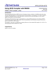
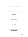
Figure 1-1 shows block diagrams of the 56800E system buses, their communication with internal
memories and the IP bus interface, and the internal connections to each unit of the 56800E core. Figure 1-2
shows the peripherals and control blocks connected to the IP bus bridge.
Freescale Semiconductor
1-3
Device Overview
DSP56800E Core
Program Control Unit
PC
LA
LA2
HWS0
HWS1
FIRA
OMR
SR
LC
LC2
FISR
Address
Generation
Unit
(AGU)
Instruction
Decoder
Interrupt
Unit
ALU1
ALU2
R0
R1
R2
R3
R4
R5
N
SP
M01
N3
Looping
Unit
Program
Memory
XAB1
XAB2
PAB
PDB
Data/
Program
RAM
CDBW
CDBR
XDB2
A2
B2
C2
D2
BitManipulation
Unit
Enhanced
OnCE™
JTAG TAP
Y
A1
B1
C1
D1
Y1
Y0
X0
MAC and ALU
A0
B0
C0
D0
IP bus
Interface
Data
Arithmetic
Logic Unit
(ALU)
Multi-Bit Shifter
Figure 1-1. 56800E Core Block Diagram
1-4
Freescale Semiconductor
Device Overview
IP bus Bridge
Port A
Port B
OCCS
Crystal
GPIOB7
GPIOB6
GPIOB5
GPIOB4
GPIOB3
GPIOB2
GPIOB1
GPIOB0
Port C
COSC
ROSC
GPIOC7
GPIOC6
GPIOC5
GPIOC4
GPIOC3
GPIOC2
GPIOC1
GPIOC0
Port D
COP
Second Clock source
System
Clock
GPIOA7
GPIOA6
GPIOA5
GPIOA4
GPIOA3
GPIOA2
GPIOA1
GPIOA0
GPIOD3
GPIOD2
GPIOD1
GPIOD0
Port E
RTC
GPIOE7
GPIOE6
GPIOE5
GPIOE4
GPIOE3
GPIOE2
GPIOE1
GPIOE0
RESET
SIM
PMC
1 kHz
INTC
SPI
SCI
Dual Timer (TMR)
PWM
PWM Synch
PWM Input Mux
CMP0
GPIO MUX
I2C
CMP1
CMP2
PDB
Trigger A
PreTrigger A
ANA15
PGA0
Trigger B
ADCB
PreTrigger B
ANB15
Port F
ADCA
GPIOF3
GPIOF2
GPIOF1
GPIOF0
PGA1
Figure 1-2. Peripheral Subsystem
Freescale Semiconductor
1-5
Device Overview
1.3
•
•
•
•
•
•
•
•
•
•
•
•
•
•
•
1.4
•
•
•
1.5
•
•
1.6
•
•
1-6
High Performance Core
Efficient 16-bit 56800E family Digital Signal Controller (DSC) engine with dual Harvard
architecture
Up to 32 Million Instructions Per Second (MIPS) at 32 MHz core frequency
155 Basic Instructions in conjunction with up to 20 address modes
Single-cycle 16 × 16-bit parallel Multiplier-Accumulator (MAC)
Four 36-bit accumulators, including extension bits
32-bit arithmetic and logic multi-bit shifter
Parallel instruction set with unique DSP addressing modes
Hardware DO and REP loops
Three internal address buses
Four internal data buses
Instruction set supports both DSP and controller functions
Controller-style addressing modes and instructions for compact code
Efficient C compiler and local variable support
Software subroutine and interrupt stack with depth limited only by memory
JTAG/Enhanced On-Chip Emulation (OnCE) for unobtrusive, processor speed-independent,
real-time debugging
Operation Range
From power-on-reset: Approximately 1.9 V to 3.6 V
Operating: 1.8 V to 3.6 V (power supplies and input/output)
Ambient temperature operating range: -40 C to 105 C
Memory Configuration
Up to 16 Kbytes program flash memory with flash security protection
2 Kbytes unified program/data RAM
Module Configuration
One 6-channel PWM module
— Up to 96 MHz PWM operating clock
— 15 bits of resolution
— Center-Aligned and edge-aligned PWM signal mode
— Four programmable fault inputs with programmable digital filter
— Double-Buffered PWM registers
Each complementary PWM signal pair allows selection of a PWM supply source from:
— PWM generator
Freescale Semiconductor
Device Overview
•
•
•
•
•
— Internal timers
— Analog comparator outputs
Two independent 12-bit analog-to-digital converters (ADCs)
— 3.042 s for first 10- or 12-bit ADC conversion
— 2.5 s for subsequent 10- or 12-bit ADC conversions
— Up to 28 analog inputs (internal and external) per ADC
— Output formatted in 12-, 10-, or 8-bit right-justified unsigned format
— Single or continuous conversion (automatic return to idle after single conversion)
— Configurable sample time and conversion speed/power
— Conversion complete flag and interrupt
— Input clock selectable from up to four sources
— Operation in wait or stop modes for lower noise operation
— Asynchronous clock source for lower noise operation
— Can be configured to take two samples (with no software reconfiguration required) based on
hardware triggers during ping-pong mode
— Support simultaneous and software-triggering conversions
— Automatic compare with interrupt for less-than, or greater-than or equal-to, programmable
value
— Temperature sensor
Two differential programmable gain amplifiers (PGA)
— Sampled PGA architecture
— Common mode noise and offset are automatically cancelled out (2–4 consecutive samples
required for noise/offset cancellation)
— Sample is able to be synchronized with PWM operation by using the PWM sync output and
programmable delay block
— Sampling time can be precisely controlled (to less than 0.1 s)
— Several programmable gains (1, 2, 4, 8, 16, and 32)
— 0.14 MSPS maximum
— Selectable tradeoff for slower/low power versus faster/more power
— Rail-to-rail input voltage range
— Single-ended output routed directly to on-chip ADCs ANA15 and ANB15
Available software and hardware triggers
Includes additional calibration features:
— Offset calibration eliminates any errors in the internal reference used to generate the VDDA/2
output center point
— Gain calibration can be used to verify the gain of the overall data path
— Both features require software correction of the ADC result
One high-speed serial communication interface (SCI) with LIN slave functionality
Freescale Semiconductor
1-7
Device Overview
•
•
•
•
•
1-8
— Max baud rate of 6 Mbit/s when using 3 system clock at up to 96 MHz.
— Full-duplex or single-wire operation
— Two receiver wake-up methods:
– Idle line
– Address mark
One serial peripheral interface (SPI)
— Full-duplex operation
— Master and slave modes
— Programmable Length Transactions (2 to 16 bits)
— Programmable transmit and receive shift order (MSB as first or last bit transmitted)
— Maximum slave module frequency = module clock frequency/2
One dual-channel 16-bit multi-purpose timer module (TMR)
— Up to 96 MHz operating clock
— Two independent 16-bit counter/timers with cascading capability
— Each timer has capture and compare capability
— Up to 12 operating modes
— Four external inputs and two external outputs
One programmable interval timer (PIT)
— 16-bit counter with programmable counter modulo
— Interrupt capability
Real-time counter (RTC) which can be used to implement a real-time clock
— 8-Bit up-counter
— Three software-selectable clock sources for input to prescaler with selectable binary-based and
decimal-based divider values
– 1 kHz internal low-power oscillator
– External crystal oscillator/external clock source
– System bus (IPBus up to 32 MHz)
One 16-bit programmable delay block (PDB)
— 16-bit counter with programmable counter modulo and delay time
— Counter is initiated by positive transition of internal or external trigger pulse
— Supports two independently controlled delay pulses used to synchronize PGA and ADC
conversions with input
— trigger event
— Two PDB outputs can be ORed together to schedule two conversions from one input trigger
event
— PDB outputs can be used to schedule precise edge placement for a pulsed output that generates
the control signal for the CMP windowing comparison
— Supports continuous or single-shot mode
Freescale Semiconductor
Device Overview
•
•
•
•
•
•
•
— Supports Bypass mode
One inter-integrated circuit (I2C) port
— Operates up to 400 kbps
— Supports both master and slave operation
— Supports both 10-bit address mode and broadcasting mode
— Supports System Management Bus (SMBus) version 2
Computer operating properly (COP)/watchdog timer capable of selecting different clock sources
— Programmable prescaler and timeout period
— Programmable wait, stop, and partial power-down mode operation
— Causes a loss of reference reset 128 cycles after a loss of the reference clock to the PLL is
detected
— Choice of clock sources from four sources in support of EN60730 and IEC61508:
– On-chip relaxation oscillator
– External crystal oscillator/external clock source
– System clock (IPBus)
– On-chip low-power 1 kHz oscillator
Clock sources
— On-chip 8 MHz relaxation oscillator
— On-chip 1 kHz clock
— External clock (32 kHz or 8 MHz): crystal oscillator, ceramic resonator, and external clock
source
Phase lock loop (PLL) provides a high-speed clock to the core and peripherals
— Provides 3x system clock to PWM, dual timer, and SCI
— Loss of lock interrupt
— Loss of reference clock interrupt
Three analog comparators (CMPs)
— Selectable input source includes external pins, internal DACs
— Programmable output polarity
— Output can drive timer input, PWM fault input, PWM source, external pin output, and trigger
ADCs
— Output falling- and rising-edge detection able to generate interrupts
Up to 40 general-purpose I/O (GPIO) pins
— Individual setting of each pin in peripheral or GPIO mode
— Individual input/output direction control for each pin in GPIO mode
— Hysteresis and configurable pullup device on all input pins
— Configurable slew rate and drive strength and optional input low-pass filters on all output pins
— 20 mA sink/source current
Power management controller (PMC)
Freescale Semiconductor
1-9
Device Overview
—
—
—
—
—
—
—
•
1.7
1.7.1
On-chip regulator for digital and analog circuitry to lower cost and reduce noise
Integrated power-on reset (POR)
Low-voltage interrupt with a user-selectable trip voltage of 1.81 V or 2.31 V
Selectable brown-out reset
RUN, WAIT, and STOP modes
Low-power RUN, WAIT, and STOP modes
Partial Power Down mode
– RAM, PMC, and COP remain powered
– Rest of the chip is shut down for extreme power savings
— Each peripheral can be individually disabled to save power
— Integrated 1 kHz oscillator
JTAG/EOnCE debug programming interface for real-time debugging
— IEEE 1149.1 Joint Test Action Group (JTAG) interface
— EOnCE interface for real-time debugging
System Clock Generation and Distribution
Clock Generation
The MC56F8006/MC56F8002 has numerous options for clock generation:
• On-chip relaxation oscillator (ROSC). This module nominally generates an 8 MHz clock signal. It
is also capable of operating at 400 kHz when the device is in low-power mode.
• Very low power (VLP) crystal oscillator (COSC). This VLP module is designed for use with a
32 kHz crystal (low range mode), or a crystal or resonator in the 1 to 16 MHz range (high range
mode). When used with the on-chip PLL, the maximum crystal/resonator frequency is 10 MHz.
• Off-chip external oscillator.
• 1 kHz low-power oscillator. This clock may be used by the COP module to wake the device from
partial power down mode.
• Asynchronous ADC clock sources. There are two, one for each ADC hard block. They may be used
to schedule ADC conversions asynchronously from the system clocks to reduce noise.
• The JTAG port is clocked asynchronously from the rest of the chip using the TCK signal supplied
from off-chip.
1.7.2
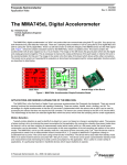
Clock Distribution
Figure 1-3 illustrates how the various clock frequencies are used on the device.
1-10
Freescale Semiconductor
Device Overview
COSC
ROSC
1 kHz
COP
2x system
clock
PMC
Flash
RTC
RAM
DSC
core &
related
SPI
IIC
PIT
div 2
1x or 3x peripheral/system clock rate
OCCS
HS Perf CLK
SIM
Note:
•
•
•
GP
Timers
PWM
SCI
CMPs
ALTCLK is an optional clock provided for ADC conversions. On this device, it is used to
cross-link the internal asynchronous ADC clocks.
All peripheral clocks can be individually gated off within the SIM
The COSC, COP, PMC and RTC all continue to operate in partial power down mode.
Both COP and RTC can signal the PMC to exit PPD mode.
ADCs
& PGAs
GPIO
ALTCLK
Figure 1-3. System Clock Distribution Diagram
The external oscillator, COSC, and ROSC can all be used as the PLL reference clock to generate 2x system
clock. This signal runs at 2 the DSC core frequency. It is divided by two within the SIM to ensure a 50%
duty cycle for clocks distributed across the chip. The external oscillator, COSC, and ROSC can also be
used as 2x system clock directly.
1.7.3
Communication Between Peripherals
Peripherals are optimized for specific applications, and in many cases, their integration on-chip is
optimized as well. This section outlines the communication between various peripherals on this device.
The two general-purpose timers can access the outputs of the three comparators (CMP0_OUT,
CMP1_OUT, and CMP2_OUT) as T0, T1, and TIN2 respectively. The muxing is controlled via the
peripheral pin enable registers in the SIM. T0 and T1 timer pins can operate as either timer input or output
pins. TIN2 and TIN3 are input pins only.
The HSCMP WINDOW/SAMPLE input can be supplied from PDB TriggerA/B or Timer 0/1 outputs.
Muxing is controlled via internal peripheral select registers in the SIM.
The SCI, SPI, IIC are stand alone communications peripherals and do not communicate with other blocks
on chip.
Each ADC contains a temperature sensor. Outputs of temperature sensors, PGAs, on-chip regulators, and
VDDA are internally routed to the ADC inputs.
• Internal PGA0 output is available on ANA15
Freescale Semiconductor
1-11
Device Overview
•
•
•
•
•
•
•
•
•
•
•
•
Internal PGA0 positive input calibration voltage is available on ANA16
Internal PGA0 negative input calibration voltage is available on ANA17
Internal PGA1 output is available on ANB15
Internal PGA1 positive input calibration voltage is available on ANB16
Internal PGA1 negative input calibration voltage is available on ANB17
ADCA temperature sensor is available on ANA26
ADCB temperature sensor is available on ANB26
Output of on-chip digital voltage regulator is routed to ANA24
Output of on-chip analog voltage regulator is routed to ANA25
Output of on-chip small voltage regulator for ROSC is routed to ANB24
Output of on-chip small voltage regulator for PLL is routed to ANB25
VDDA is routed to ANA27 and ANB27
The comparators, timers, and PWM_reload_sync output can be connected to the programmable delay
block (PDB) trigger input. The PDB pre-trigger A and trigger A outputs are connected to the ADCA and
PGA0 hardware trigger inputs. The PDB pre-trigger B and trigger B outputs are connected to the ADCB
and PGA1 hardware trigger inputs. When the input trigger of PDB is asserted, PDB trigger and pre-trigger
outputs are asserted after a delay of a pre-programmed period.
1-12
Freescale Semiconductor
Chapter 2
Analog-to-Digital Converter (ADC)
2.1
Introduction
The 12-bit analog-to-digital converter (ADC) is designed for operation with a DSC.
In this chapter, the term ADCn represents both ADC modules:
• ADC0 (n is 0) is the same as ADCA.
• ADC1 (n is 1) is the same as ADCB.
Also:
• ADCSC1 stands for ADCn_ADCSC1A and/or ADCn_ADCSC1B.
• ADCSC2 stands for ADCn_ADCSC2.
• ADCR stands for ADCn_ADCRA and/or ADCn_ADCRB.
2.1.1
Features
Features of the ADC module include:
• Input voltage values may range from VSSA to VDDA.
• Up to 28 analog inputs.
• Output formatted in 12-, 10-, or 8-bit right-justified format.
• Single or continuous conversion (automatic return to idle after single conversion).
• Configurable sample time and conversion speed/power.
• Conversion complete flag and interrupt.
• Input clock selectable from up to four sources.
• Operation in wait or stop modes for lower noise operation.
• Asynchronous clock source for lower noise operation.
• Support of simultaneous and software triggering conversions.
• Temperature sensors that are routed to ANA26 and ANB26.
• Can be configured to take two samples (with no software reconfiguration required) based on
hardware triggers during ping-pong mode.
2.1.2
Related Material
This block interfaces directly with the programmable gain amplifier and programmable delay block. See
Chapter 5, “Programmable Delay Block (PDB),” for additional information.
Freescale Semiconductor
2-1
Analog-to-Digital Converter (ADC)
2.1.3
Block Diagram
Figure 2-1 provides a block diagram of the ADC module.
ADCSC1A
ADCSC1B
ADIV
ADLPC
MODE
ADLSMP
ADTRG
complete
ADCO
AIEN
COCO
ADCH
Sample
selector
SSEL[1:0] = {PreTriggerB, PreTriggerA}
ADCCFG
ADCSC1
1 2
2
sample_select 3
1
ADICLK
0
Async
Clock Gen
ADACK
DSC
CORE
STOP
ADHWT
³2
ALTCLK
abort
transfer
convert
sample
initialize
Bus Clock
ADCK Clock
Divide
Control Sequencer
ECC
•••
AD0
AIEN1
2
COCO
ADVIN
exported clock
Interrupt
SAR Converter
AD27
VDDA
VSSA
0
ADCn_ADCRA
1
sample_select
3
ADCn_ADCRB
Figure 2-1. ADC Block Diagram
2.2
External Signal Description
The ADC module supports up to 28 separate analog inputs.
Table 2-1. Signal Properties
2.2.1
Name
Function
AD27–AD0
Analog Channel inputs
Analog Channel Inputs (ADn)
The ADC module supports up to 28 separate analog inputs. An input is selected for conversion through
the ADCH channel select bits.
2-2
Freescale Semiconductor
Analog-to-Digital Converter (ADC)
2.3
Register Definition
Memory mapped registers shown in Table 2-2 control and monitor operation of the ADC.
Table 2-2. ADC Registers
2.3.1
Register Name
Address
Offset
Description
ADCn_ADCSC1A
0x0
Status and control register 1A
ADCn_ADCSC2
0x1
Status and control register
Reserved
0x2
—
Reserved
0x3
—
Reserved
0x4
—
Reserved
0x5
—
ADCn_ADCCFG
0x6
Configuration register
Reserved
0x7
—
Reserved
0x8
—
Reserved
0x9
—
ADCn_ADCSC1B
0xA
Status and control register 1B
ADCn_ADCRA
0xB
Data result register A
ADCn_ADCRB
0xC
Data result register B
Reserved
0xD
—
Reserved
0xE
—
Status and Control Register 1A and 1B (ADCn_ADCSC1A and
ADCn_ADCSC1B)
This section describes the function of the ADC status and control registers, ADCn_ADCSC1A and
ADCn_ADCSC1B. These registers have identical fields, and are used in a “ping-pong” approach to
control ADC operation. At any one point in time, only one of ADCn_ADCSC1A and ADCn_ADCSC1B
is actively controlling the ADC analog core. It is possible to write to ADCn_ADCSC1A while
ADCn_ADCSC1B is driving a conversion, and vice-versa. Writing ADCn_ADCSC1A while it is actively
controlling a conversion aborts the current conversion and initiates a new conversion (if the ADCH bits
are equal to a value other than all 1s). The same applies to ADCn_ADCSC1B.
Address: ADCn_BASE + 0x0
R
Access: User read/write
15
14
13
12
11
10
9
8
7
0
0
0
0
0
0
0
0
COCO
0
0
0
0
0
0
0
0
0
W
Reset
6
5
4
3
AIEN ADCO
0
0
2
1
0
1
1
ADCH
1
1
1
Figure 2-2. Status and Control Register 1A (ADCn_ADCSC1A)
Freescale Semiconductor
2-3
Analog-to-Digital Converter (ADC)
Address: ADCn_BASE + 0xA
R
Access: User read/write
15
14
13
12
11
10
9
8
7
0
0
0
0
0
0
0
0
COCO
0
0
0
0
0
0
0
0
0
W
Reset
6
5
4
3
AIEN ADCO
0
0
2
1
0
1
1
ADCH
1
1
1
Figure 2-3. Status and Control Register 1B (ADCn_ADCSC1B)
Table 2-3. ADCn_ADCSC1A/B Register Field Descriptions
Field
15–8
Description
Reserved. Read and write as zero
7
COCO
Conversion Complete Flag. The COCO flag is a read-only bit that is set each time a conversion is completed
when the compare function is disabled (ACFE = 0). When the compare function is enabled (ACFE = 1) the COCO
flag is set upon completion of a conversion only if the compare result is true. This bit is cleared whenever
ADCSC1 is written or whenever ADCn_ADCRA or ADCn_ADCRB is read.
0 Conversion not completed
1 Conversion completed
6
AIEN
Interrupt Enable. AIEN is used to enable conversion complete interrupts. When COCO becomes set while AIEN
is high, an interrupt is asserted.
0 Conversion complete interrupt disabled
1 Conversion complete interrupt enabled
5
ADCO
Continuous Conversion Enable. ADCO is used to enable continuous conversions.
0 One conversion following a write to the ADCSC1 when software triggered operation is selected, or one
conversion following assertion of ADHWT when hardware triggered operation is selected.
1 Continuous conversions initiated following a write to ADCSC1 when software triggered operation is selected.
Continuous conversions are initiated by an ADHWT event when hardware triggered operation is selected.
4–0
ADCH
Input Channel Select. The ADCH bits form a 5-bit field that is used to select one of the input channels. The input
channels are detailed in Figure 2-4.
The analog-to-digital converter subsystem is turned off when the channel select bits are all set to 1. This feature
allows for explicit disabling of the ADC and isolation of the input channel from all sources. Terminating continuous
conversions this way prevents an additional, single conversion from being performed. It is not necessary to set
the channel select bits to all 1s to place the ADC in a low-power state when continuous conversions are not
enabled because the module automatically enters a low-power state when a conversion completes.
Table 2-4. Input Channel Select
2-4
ADCH
Input Select
ADCH
Input Select
00000
AD0
10000
AD16
00001
AD1
10001
AD17
00010
AD2
10010
AD18
00011
AD3
10011
AD19
00100
AD4
10100
AD20
00101
AD5
10101
AD21
00110
AD6
10110
AD22
Freescale Semiconductor
Analog-to-Digital Converter (ADC)
Table 2-4. Input Channel Select (continued)
2.3.2
ADCH
Input Select
ADCH
Input Select
00111
AD7
10111
AD23
01000
AD8
11000
AD24
01001
AD9
11001
AD25
01010
AD10
11010
AD26
01011
AD11
11011
AD27
01100
AD12
11100
Reserved
01101
AD13
11101
VREFH
01110
AD14
11110
VREFL
01111
AD15
11111
Module disabled
Status and Control Register 2 (ADCn_ADCSC2)
The ADCn_ADCSC2 register is used to control the conversion trigger and conversion active of the ADC
module
Address: ADCn_BASE + 1
R
Access: User read/write
15
14
13
12
11
10
9
8
7
0
0
0
0
0
0
0
0
ADACT
0
0
0
0
0
0
0
0
0
W
Reset
6
ADTRG
0
5
4
3
0
0
0
0
0
0
2
1
0
ECC REFSEL
0
0
0
Figure 2-4. Status and Control Register 2 (ADCn_ADCSC2)
Table 2-5. ADCn_ADCSC2 Register Field Descriptions
Field
15–8
Description
Reserved. Read and write as zero
7
ADACT
Conversion Active. ADACT indicates that a conversion is in progress. ADACT is set when a conversion is initiated
and cleared when a conversion is completed or aborted.
0 Conversion not in progress
1 Conversion in progress
6
ADTRG
Conversion Trigger Select. ADTRG is used to select the type of trigger to be used for initiating a conversion. Two
types of trigger are selectable: software trigger and hardware trigger. When software trigger is selected, a
conversion is initiated following a write to ADCn_ADCSC1A or ADCn_ADCSC1B. When hardware trigger is
selected, a conversion is initiated following the assertion of the ADHWT input.
0 Software trigger selected
1 Hardware trigger selected
5–3
Reserved. Read and write as zero
Freescale Semiconductor
2-5
Analog-to-Digital Converter (ADC)
Table 2-5. ADCn_ADCSC2 Register Field Descriptions (continued)
Field
Description
2
ECC
Enable Continuous Clock output. This bit gates the exported clock output of the ADC module. Set to zero to
conserve power if the ADC clock output is not required by other on-chip devices.
0 Output clock is forced inactive
1 Output clock is enabled
1–0
REFSEL
Voltage Reference Selection. REFSEL bits are used to select the voltage reference source used for conversions.
00 Analog supply pin pair (VDDA/VSSA)
01 Analog supply pin pair (VDDA/VSSA)
10 On-chip bandgap reference / VSSA
11 Analog supply pin pair (VDDA/VSSA)
2.3.3
Data Result Registers A and B (ADCn_ADCRA and ADCn_ADCRB)
Address: ADCn_BASE + B
R
15
14
0
ADR
11
0
0
13
Access: User read/write
12
11
10
9
8
7
6
5
4
3
ADR
ADR9 ADR8 ADR7 ADR6 ADR5 ADR4 ADR3 ADR2 ADR1 ADR0
10
2
1
0
0
0
0
0
0
0
W
Reset
0
0
0
0
0
0
0
0
0
0
0
Figure 2-5. Data Result Register (ADCn_ADCRA)
Address: ADCn_BASE + C
R
15
14
0
ADR
11
0
0
13
Access: User read/write
12
11
10
9
8
7
6
5
4
3
ADR
ADR9 ADR8 ADR7 ADR6 ADR5 ADR4 ADR3 ADR2 ADR1 ADR0
10
2
1
0
0
0
0
0
0
0
W
Reset
0
0
0
0
0
0
0
0
0
0
0
Figure 2-6. Data Result Register (ADCn_ADCRB)
In 12-bit operation, ADCR[14:3] contains the full 12-bit conversion result. In 10-bit mode, ADCR[12:3]
contains the 10-bit conversion result and ADR[14:13] are both zero. Likewise, when configured for 8-bit
mode, the result is in ADR[10:3] and ADR[14:11] are zero.
ADCR is updated each time a conversion completes.
In the case that the MODE bits are changed, any data in ADCR becomes invalid.
2.3.4
Configuration Register (ADCn_ADCCFG)
ADCCFG is used to select the mode of operation, clock source, clock divide, and configure for low power
or long sample time.
2-6
Freescale Semiconductor
Analog-to-Digital Converter (ADC)
Address: ADCn_BASE + 6
R
Access: User read/write
15
14
13
0
0
0
0
0
0
12
11
10
9
8
6
ADLP
C
W
Reset
7
0
0
0
0
0
0
5
ADLS
MP
ADIV
0
4
0
0
3
2
MODE
0
0
1
0
ADICLK
0
0
Figure 2-7. Configuration Register (ADCn_ADCCFG)
Table 2-6. ADCn_ADCCFG Register Field Descriptions
Field
Description
7
ADLPC
Low Power Configuration. ADLPC controls the speed and power configuration of the analog-to-digital converter.
This is used to optimize power consumption when higher sample rates are not required.
0 High speed configuration
1 Low power configuration: The power is reduced at the expense of maximum clock speed.
6, 5
ADIV
Clock Divide Select. ADIV select the divide ratio used by the ADC to generate the internal clock ADCK. Table 2-7
shows the available clock configurations.
4
ADLSMP
Long Sample Time Configuration. ADLSMP selects between long and short sample time. This adjusts the
sample period to allow higher impedance inputs to be accurately sampled or to maximize conversion speed for
lower impedance inputs. Longer sample times can also be used to lower overall power consumption when
continuous conversions are enabled if high conversion rates are not required.
0 Short sample time
1 Long sample time
3, 2
MODE
Conversion Mode Selection. MODE bits are used to select between 12-, 10- or 8-bit operation. See Table 2-8.
1, 0
ADICLK
Input Clock Select. ADICLK bits select the input clock source to generate the internal clock ADCK. See Table 2-9.
Table 2-7. Clock Divide Select
ADIV
Divide Ratio
Clock Rate
00
1
Input clock
01
2
Input clock 2
10
4
Input clock 4
11
8
Input clock 8
Table 2-8. Conversion Modes
Freescale Semiconductor
MODE
Mode Description
00
8-bit conversion (N=8)
01
12-bit conversion (N=12)
10
10-bit conversion (N=10)
11
Reserved
2-7
Analog-to-Digital Converter (ADC)
Table 2-9. Input Clock Select
2.4
ADICLK
Selected Clock Source
00
Bus clock
01
Bus clock divided by 2
10
Alternate clock (ALTCLK)
11
Asynchronous clock (ADACK)
Functional Description
The ADC module is disabled during reset or when the ADCH bits are all high. The module is idle when a
conversion has completed and another conversion has not been initiated. When idle, the module is in its
lowest power state.
The ADC can perform an analog-to-digital conversion on any of the software selectable channels. In 12-bit
and 10-bit mode, the selected channel voltage is converted into a 12-bit digital result. In 8-bit mode, the
selected channel voltage is converted into a 9-bit digital result.
When the conversion is completed, the result is placed in the data register. In 10-bit mode, the result is
rounded to 10 bits and placed in the data register. In 8-bit mode, the result is rounded to 8 bits and placed
in ADCR. The conversion complete flag (COCO) is then set and an interrupt is generated if the conversion
complete interrupt has been enabled (AIEN = 1).
2.4.1
Clock Select and Divide Control
One of four clock sources can be selected as the clock source for the ADC module. This clock source is
then divided by a configurable value to generate the input clock to the converter (ADCK). The clock is
selected from one of the following sources by means of the ADICLK bits.
• The bus clock, which is equal to the frequency at which software is executed. This is the default
selection following reset.
• The bus clock divided by 2. For higher bus clock rates, this allows a maximum divide by 16 of the
bus clock.
• The asynchronous clock (ADACK) — This clock is generated from a clock source within the ADC
module. When selected as the clock source this clock remains active while the DSC core is in wait
or stop mode and allows conversions in these modes for lower noise operation.
Whichever clock is selected, its frequency must fall within the specified frequency range for ADCK. If the
available clocks are too slow, the ADC does not perform according to specifications. If the available clocks
are too fast, then the clock must be divided to the appropriate frequency. This divider is specified by the
ADIV bits and can be divide-by 1, 2, 4, or 8.
2.4.2
Hardware Trigger
The ADC module has a selectable asynchronous hardware conversion trigger, ADHWT, that is enabled
when the ADTRG bit is set. See Figure 3-10 for how ADHWT is used to interface to the PGA.
2-8
Freescale Semiconductor
Analog-to-Digital Converter (ADC)
When hardware trigger is enabled (ADTRG=1), a conversion is initiated on the rising edge of ADHWT.
If a conversion is in progress when a rising edge occurs, the rising edge is ignored. In continuous convert
configuration, only the initial rising edge to launch continuous conversions is observed. The hardware
trigger function operates in conjunction with any of the conversion modes and configurations.
Figure 2-1 includes the following code segment to describe the operation of the sample select function:
if (ADTRG==0) {
// software trigger selected
sample_select=0;
} else {
// hardware trigger selected
if (posedge SSEL[0] and NOT posedge SSEL[1]) sample_select = 0;
else if (posedge SSEL[1] and NOT posedge SSEL[0]) sample_select = 1;
}
// else NO CHANGE
This implies that ADCn_ADCSC1A and ADCn_ADCRA are used whenever hardware triggering is not in
use. When hardware triggering is used, then edges on SSEL[1:0] determine which set of control/result
registers is used. A positive edge on SSEL[0] but not on SSEL[1] selects ADCn_ADCSC1A /
ADCn_ADCRA. A positive edge on SSEL[1] but not on SSEL[0] selects ADCn_ADCSC1B /
ADCn_ADCRB. Simultaneous changes on both SSEL[1] and SSEL[0] result in no change to the currently
selected control/register set.
In essence, SSEL[1:0] act as control bits to pre-specify the control/result registers to use for the next
conversion.
2.4.3
Conversion Control
Conversions can be performed in 12-bit mode, 10-bit mode, or 8-bit mode as determined by the MODE
bits. Conversions can be initiated by either a software or hardware trigger. In addition, the ADC module
can be configured for low power operation, long sample time, and continuous conversion.
2.4.3.1
Initiating Conversions
A conversion is initiated:
• Following a write to ADCSC1 (with ADCH bits not all 1s) if software triggered operation is
selected.
• Following a hardware trigger (ADHWT) event if hardware triggered operation is selected.
• Following the transfer of the result to the data registers when continuous conversion is enabled.
If continuous conversions are enabled a new conversion is automatically initiated after the completion of
the current conversion. In software triggered operation, continuous conversions begin after ADCSC1 is
written and continue until aborted. In hardware triggered operation, continuous conversions begin after a
hardware trigger event and continue until aborted.
2.4.3.2
Completing Conversions
A conversion is completed when the result of the conversion is transferred into the data result register,
ADCn_ADCRA or ADCn_ADCRB. This is indicated by setting the COCO bit in ADCn_ADCSC1A or
ADCn_ADCSC1B. An interrupt is generated if AIEN is high at the time that COCO is set.
Freescale Semiconductor
2-9
Analog-to-Digital Converter (ADC)
2.4.3.3
Aborting Conversions
Any conversion in progress is aborted when:
• A write to ADCSC1 occurs (the current conversion is aborted and a new conversion is initiated if
ADCH are not all 1s).
• A write to ADCSC2, ADCCFG, or ADCCV occurs. This indicates a mode of operation change has
occurred and the current conversion is therefore invalid. No new conversion is initiated.
• The DSC core is reset.
• The DSC core enters stop mode with ADACK not enabled.
When a conversion is aborted, the contents of the data registers, ADCn_ADCRA/B, are not altered but
continue to be the values transferred after the completion of the last successful conversion. In the case that
the conversion was aborted by a reset, ADCR returns to its reset state.
2.4.3.4
Power Control
The ADC module remains in its idle state until a conversion is initiated. If ADACK is selected as the
conversion clock source, the ADACK clock generator is also enabled.
Power consumption can be reduced by setting ADLPC. This results in a lower maximum value for fADCK.
2.4.3.5
Sample Time and Total Conversion Time
The total conversion time depends on the sample time (as determined by ADLSMP), the IP bus frequency,
the conversion mode (8-bit, 10-bit or 12-bit), and the frequency of the conversion clock (fADCK). After the
module becomes active, sampling of the input begins. ADLSMP is used to select between short (3.5
ADCK cycles) and long (23.5 ADCK cycles) sample times.When sampling is complete, the converter is
isolated from the input channel and conversion is performed to determine the digital value of the analog
signal. The result of the conversion is transferred to ADCR upon completion of the conversion.
If the bus frequency is less than the fADCK frequency, precise sample time for continuous conversions
cannot be guaranteed when short sampling is enabled (ADLSMP=0). If the bus frequency is less than
1/11th of the fADCK frequency, precise sample time for continuous conversions cannot be guaranteed when
long sampling is enabled (ADLSMP=1).
The maximum total conversion time for different conditions is summarized in Table 2-10.
Table 2-10. Total Conversion Time vs. Control Conditions
2-10
Conversion Type
ADICLK
ADLSMP
Max Total Conversion Time
Single or first continuous 8-bit
0x, 10
0
20 ADCK cycles + 5 bus clock cycles
Single or first continuous 10-bit or 12-bit
0x, 10
0
23 ADCK cycles + 5 bus clock cycles
Single or first continuous 8-bit
0x, 10
1
40 ADCK cycles + 5 bus clock cycles
Single or first continuous 10-bit or 12-bit
0x, 10
1
43 ADCK cycles + 5 bus clock cycles
Single or first continuous 8-bit
11
0
5 s + 20 ADCK + 5 bus clock cycles
Single or first continuous 10-bit or 12-bit
11
0
5 s + 23 ADCK + 5 bus clock cycles
Freescale Semiconductor
Analog-to-Digital Converter (ADC)
Table 2-10. Total Conversion Time vs. Control Conditions (continued)
Conversion Type
ADICLK
ADLSMP
Max Total Conversion Time
Single or first continuous 8-bit
11
1
5 s + 40 ADCK + 5 bus clock cycles
Single or first continuous 10-bit or 12-bit
11
1
5 s + 43 ADCK + 5 bus clock cycles
Subsequent continuous 8-bit;
fBUS fADCK
xx
0
17 ADCK cycles
Subsequent continuous 10-bit or 12-bit;
fBUS fADCK
xx
0
20 ADCK cycles
Subsequent continuous 8-bit;
fBUS fADCK/11
xx
1
37 ADCK cycles
Subsequent continuous 10-bit or 12-bit;
fBUS fADCK/11
xx
1
40 ADCK cycles
The maximum total conversion time is determined by the clock source chosen and the divide ratio selected.
The clock source is selectable by the ADICLK bits, and the divide ratio is specified by the ADIV bits. For
example, in 10-bit mode, with the bus clock selected as the input clock source, the input clock divide-by-1
ratio selected, and a bus frequency of 8 MHz, then the conversion time for a single conversion is:
Eqn. 2-1
23 ADCK Cyc
Conversion time =
8 MHz/1
5 bus Cyc
+
8 MHz
= 3.5 s
Number of bus cycles = 3.5 s x 8 MHz = 28 cycles
NOTE
The ADCK frequency must be between fADCK minimum and fADCK
maximum to meet ADC specifications.
2.4.4
Temperature Sensor
Each ADC module includes a temperature sensor whose output is connected to one of the ADC analog
channel inputs. Equation 2-2 provides an approximate transfer function of the temperature sensor.
Temp = 25 – ((VTEMP -VTEMP25) m)
Eqn. 2-2
where:
VTEMP is the voltage of the temperature sensor channel at the ambient temperature.
VTEMP25 is the voltage of the temperature sensor channel at 25C.
m is the hot or cold voltage versus temperature slope in V/C.
For temperature calculations, use the VTEMP25 and m values from the ADC Electricals table in the data
sheet.
Freescale Semiconductor
2-11
Analog-to-Digital Converter (ADC)
In application code, the user reads the temperature sensor channel, calculates VTEMP, and compares to
VTEMP25. If VTEMP is greater than VTEMP25 the cold slope value is applied in Equation 2-2. If VTEMP is
less than VTEMP25 the hot slope value is applied in Equation 2-2.
For more information on using the temperature sensor, consult AN3031.
2.4.5
DSC Core Wait Mode Operation
The WAIT instruction puts the DSC core in a lower power-consumption standby mode from which
recovery is very fast because the clock sources remain active. If a conversion is in progress when the DSC
core enters wait mode, it continues until completion. Conversions can be initiated while the DSC core is
in wait mode by means of the hardware trigger or if continuous conversions are enabled.
The bus clock, bus clock divided by two, and ADACK are available as conversion clock sources while in
wait mode.
A conversion complete event sets the COCO and generates an ADC interrupt to wake the DSC core from
wait mode if the ADC interrupt is enabled (AIEN = 1).
2.4.6
DSC Core Stop Mode Operation
The STOP instruction is used to put the DSC core in a low power-consumption standby mode during which
most or all clock sources on the DSC core are disabled.
NOTE
Use of stop mode requires the corresponding ADCn bit in SIM_SDR
register to be set.
2.4.6.1
Stop Mode with ADACK Disabled
If the asynchronous clock, ADACK, is not selected as the conversion clock, executing a STOP instruction
during an ADC conversion could result in unexpected behavior. Do not enter stop mode until all
conversions have completed when using any clock other than ADACK.
The contents of ADCR are unaffected by stop mode. After exiting from stop mode, a software or hardware
trigger is required to resume conversions.
2.4.6.2
Stop Mode with ADACK Enabled
If ADACK is selected as the conversion clock, the ADC continues operation during stop mode. The DSC’s
voltage regulator remains active during stop mode.
If a conversion is in progress when the DSC core enters stop mode, it continues until completion.
Conversions can be initiated while the DSC core is in stop mode by means of the hardware trigger or if
continuous conversions are enabled.
A conversion complete event sets the COCO and generates an ADC interrupt to wake the DSC core from
stop mode if the ADC interrupt is enabled (AIEN = 1).
2-12
Freescale Semiconductor
Analog-to-Digital Converter (ADC)
2.4.7
DSC Partial Power Down Mode Operation
The ADC module is automatically disabled when the DSC core enters PPD mode. All module registers
contain their reset values following exit from PPD mode. Therefore, the module must be re-enabled and
reconfigured following exit from PPD.
2.5
Initialization Information
This section gives an example that provides some basic direction on how a user would initialize and
configure the ADC module. The user has the flexibility of choosing between configuring the module for
8-, 10-, or 12-bit resolution, single or continuous conversion, and a polled or interrupt approach, among
many other options. Refer to Table 2-7, Table 2-8, and Table 2-9 for information used in this example.
NOTE
Hexadecimal values designated by a preceding 0x, binary values designated
by a preceding %, and decimal values have no preceding character.
2.5.1
2.5.1.1
ADC Module Initialization Example
Initialization Sequence
Before the ADC module can be used to complete conversions, an initialization procedure must be
performed. A typical sequence is as follows:
1. Update the configuration register (ADCn_ADCCFG) to select the input clock source and the
divide ratio used to generate the internal clock, ADCK. This register is also used for selecting
sample time and low-power configuration.
2. Update status and control register 2 (ADCn_ADCSC2) to select the conversion trigger (hardware
or software).
3. Update status and control register 1 (ADCn_ADCSC1) to select whether conversions are
continuous or completed only once, and to enable or disable conversion complete interrupts. The
input channel on which conversions are performed is also selected here.
2.5.1.2
Pseudo-code Example
In this example, the ADC module is set up with interrupts enabled to perform a single 10-bit conversion
at low power with a long sample time on input channel 1, where the internal ADCK clock is derived from
the bus clock divided by 1.
Freescale Semiconductor
2-13
Analog-to-Digital Converter (ADC)
Table 2-11. ADC Module Pseudo-code Example
ADC Module
ADCn_ADCCFG = 0x98 (%10011000)
ADCn_ADCSC2 = 0x00 (%00000000)
ADCn_ADCSC1A = 0x41 (%01000001)
ADCn_ADCRA = xxxx
2-14
Enabled Interrupts
Bit 7
ADLPC
1
Configures for low power (lowers
maximum clock speed)
Bit 6, 5
ADIV
00
Sets the ADCK to the input clock/1
Bit 4
ADLSMP
1
Configures for long sample time
Bit 3, 2
MODE
10
Sets mode at 10-bit conversions
Bit 1, 0
ADICLK
00
Selects bus clock as input clock source
—
ADACT
0
Flag indicates if a conversion is in
progress
Bit 6
ADTRG
0
Software trigger selected
Bit 5
—
0
Unimplemented or reserved, always
reads zero
Bit 4
—
0
Unimplemented or reserved, always
reads zero
Bit 3, 2
—
00
Unimplemented or reserved, always
reads zero
Bit 1, 0
—
00
Reserved for Freescale’s internal use;
always write zero
Bit 7
COCO
0
Read-only flag that is set when a
conversion completes
Bit 6
AIEN
1
Conversion complete interrupt enabled
Bit 5
ADCO
0
One conversion only (continuous
conversions disabled)
Bit 4–0
ADCH
00001
—
—
—
Input channel 1 selected as ADC input
channel
Holds results of conversion.
Freescale Semiconductor
Analog-to-Digital Converter (ADC)
Reset
Initialize ADC
ADCn_ADCCFG = 0x98
ADCn_ADCSC2 = 0x00
ADCn_ADCSC1 = 0x41
Check
COCO=1?
No
Yes
Read Adcr
To
Clear COCO Bit
Continue
Figure 2-8. Initialization Flowchart for Example
2.6
Application Information
This section contains information for using the ADC module in applications. The ADC has been designed
to be integrated into a DSC for use in embedded control applications.
2.6.1
External Pins and Routing
The following sections discuss the external pins associated with the ADC module and how they should be
used for best results.
2.6.1.1
Analog Input Pins
Conversions can be performed on inputs even when the pins are not configured for the ADC normal usage.
(For example, they might be configured for GPIO.) It is recommended that the pin control register bit
always be set up to use the pin as an ADC input when using a pin as an analog input. This avoids problems
with contention because the output buffer is in its high impedance state and the pullup is disabled. Also,
the input buffer draws DC current when its input is not at either VDD or VSS. Setting the pin control register
bits for all pins used as analog inputs should be done to achieve lowest operating current.
Empirical data shows that capacitors on the analog inputs improve performance in the presence of noise
or when the source impedance is high. Use of 0.01 F capacitors with good high-frequency characteristics
is sufficient. These capacitors are not necessary in all cases, but when used they must be placed as near as
possible to the package pins and be referenced to VSSA.
Freescale Semiconductor
2-15
Analog-to-Digital Converter (ADC)
For proper conversion, the input voltage must fall between VDDA and VSSA. If the input is equal to or
exceeds VREFH, the converter circuit converts the signal to 0xFFF (full scale 12-bit representation), 0x3FF
(full scale 10-bit representation) or 0xFF (full scale 8-bit representation). If the input is equal to or less
than VREFL, the converter circuit converts it to 0x000. Input voltages between VREFH and VREFL are
straight-line linear conversions. There is a brief current associated with VREFL when the sampling
capacitor is charging. The input is sampled for 3.5 cycles of the ADCK source when ADLSMP is low, or
23.5 cycles when ADLSMP is high.
For minimal loss of accuracy due to current injection, pins adjacent to the analog input pins should not be
transitioning during conversions.
2.6.2
Sources of Error
Several sources of error exist for A/D conversions. These are discussed in the following sections.
2.6.2.1
Sampling Error
For proper conversions, the input must be sampled long enough to achieve the proper accuracy. Given the
maximum input resistance of approximately 7 k and input capacitance of approximately 5.5 pF,
sampling to within 1/4LSB (at 12-bit resolution) can be achieved within the minimum sample window
(3.5 cycles @ 8 MHz maximum ADCK frequency) provided the resistance of the external analog source
(RAS) is kept below 2 k.
Higher source resistances or higher-accuracy sampling is possible by setting ADLSMP (to increase the
sample window to 23.5 cycles) or decreasing ADCK frequency to increase sample time.
2.6.2.2
Pin Leakage Error
Leakage on the I/O pins can cause conversion error if the external analog source resistance (RAS) is high.
If this error cannot be tolerated by the application, keep RAS lower than VDDAD / (2N*ILEAK) for less than
1/4LSB leakage error (N = 8 in 8-bit, 10 in 10-bit or 12 in 12-bit mode).
2.6.2.3
Noise-Induced Errors
System noise that occurs during the sample or conversion process can affect the accuracy of the
conversion. The ADC accuracy numbers are guaranteed as specified only if the following conditions are
met:
• There is a 0.1 F low-ESR capacitor from VREFH to VREFL.
• There is a 0.1 F low-ESR capacitor from VDDAD to VSSAD.
• If inductive isolation is used from the primary supply, an additional 1 F capacitor is placed from
VDDAD to VSSAD.
• VSSAD (and VREFL, if connected) is connected to VSS at a quiet point in the ground plane.
• Operate the DSC core in wait or LPstop mode before initiating (hardware triggered conversions)
or immediately after initiating (hardware or software triggered conversions) the ADC conversion.
— For software triggered conversions, immediately follow the write to the ADCSC1 with a WAIT
instruction or STOP instruction.
2-16
Freescale Semiconductor
Analog-to-Digital Converter (ADC)
•
— For LPstop mode operation, select ADACK as the clock source. Operation in LPstop reduces
VDD noise but increases effective conversion time due to stop recovery.
There is no I/O switching, input or output, on the DSC core during the conversion.
There are some situations where external system activity causes radiated or conducted noise emissions or
excessive VDD noise is coupled into the ADC. In these situations, or when the DSC core cannot be placed
in wait or LPstop or I/O activity cannot be halted, these recommended actions may reduce the effect of
noise on the accuracy:
• Place a 0.01 F capacitor (CAS) on the selected input channel to VREFL or VSSAD (this improves
noise issues but affects sample rate based on the external analog source resistance).
• Average the result by converting the analog input many times in succession and dividing the sum
of the results. Four samples are required to eliminate the effect of a 1 LSB, one-time error.
• Reduce the effect of synchronous noise by operating off the asynchronous clock (ADACK) and
averaging. Noise that is synchronous to ADCK cannot be averaged out.
2.6.2.4
Code Width and Quantization Error
The ADC quantizes the ideal straight-line transfer function into 4096 steps (in 12-bit mode). Each step
ideally has the same height (1 code) and width. The width is defined as the delta between the transition
points to one code and the next. The ideal code width for an N bit converter (in this case N can be 8, 10 or
12), defined as 1 LSB, is:
1LSB = (VREFH - VREFL) / 2N
Eqn. 2-3
There is an inherent quantization error due to the digitization of the result. For 8-bit or 10-bit conversions
the code transitions when the voltage is at the midpoint between the points where the straight line transfer
function is exactly represented by the actual transfer function. Therefore, the quantization error is 1/2 LSB
in 8- or 10-bit mode. As a consequence, however, the code width of the first (0x000) conversion is only
1/2 LSB and the code width of the last (0xFF or 0x3FF) is 1.5 LSB.
For 12-bit conversions the code transitions only after the full code width is present, so the quantization
error is -1LSB to 0LSB and the code width of each step is 1LSB.
2.6.2.5
Linearity Errors
The ADC may also exhibit non-linearity of several forms. Every effort has been made to reduce these
errors but the system should be aware of them because they affect overall accuracy. These errors are:
• Zero-scale error (EZS) (sometimes called offset) — This error is defined as the difference between
the actual code width of the first conversion and the ideal code width (1/2 LSB in 8-bit or 10-bit
modes and 1 LSB in 12-bit mode). Note, if the first conversion is 0x001, then the difference between
the actual 0x001 code width and its ideal (1 LSB) is used.
• Full-scale error (EFS) — This error is defined as the difference between the actual code width of
the last conversion and the ideal code width (1.5 LSB in 8-bit or 10-bit modes and 1 LSB in 12-bit
mode). Note, if the last conversion is 0x3FE, then the difference between the actual 0x3FE code
width and its ideal (1LSB) is used.
Freescale Semiconductor
2-17
Analog-to-Digital Converter (ADC)
•
•
•
Differential non-linearity (DNL) — This error is defined as the worst-case difference between the
actual code width and the ideal code width for all conversions.
Integral non-linearity (INL) — This error is defined as the highest-value the (absolute value of the)
running sum of DNL achieves. More simply, this is the worst-case difference of the actual
transition voltage to a given code and its corresponding ideal transition voltage, for all codes.
Total unadjusted error (TUE) — This error is defined as the difference between the actual transfer
function and the ideal straight-line transfer function, and therefore includes all forms of error.
2.6.2.6
Code Jitter, Non-Monotonicity and Missing Codes
Analog-to-digital converters are susceptible to three special forms of error. These are code jitter,
non-monotonicity, and missing codes.
Code jitter is when, at certain points, a given input voltage converts to one of two values when sampled
repeatedly. Ideally, when the input voltage is infinitesimally smaller than the transition voltage, the
converter yields the lower code (and vice-versa). However, even very small amounts of system noise can
cause the converter to be indeterminate (between two codes) for a range of input voltages around the
transition voltage. This range is normally around 1/2 LSB in 8-bit or 10-bit mode, or around 2 LSB in 12-bit
mode, and increases with noise.
This error may be reduced by repeatedly sampling the input and averaging the result. Additionally the
techniques discussed in Section 2.6.2.3, “Noise-Induced Errors,” reduce this error.
2-18
Freescale Semiconductor
Chapter 3
Programmable Gain Amplifier (PGA)
3.1
Introduction
3.1.1
Overview
The programmable gain amplifier, or PGA, is intended to operate in conjunction with the on-chip
analog-to-digital converter (ADC). By itself, the PGA has no useful function. When used to pre-process
ADC inputs, it amplifies and converts differential signals to a single-ended value, which is passed on to
the ADC for conversion to digital format.
Peripheral Bus
PGA trigger &
pre-trigger Inputs
Bus Interface
Gain & Power Controls
Sequence Control
Vin+
+
Vin-
S/H
X2
+
x4
Diff Gain Stage
+
X4
-
ADC trigger
& pre-trigger
outputs
To ADC
analog input
Diff2SE Gain Stage
Figure 3-1. Programmable Gain Amplifier Block Diagram
Features:
•
•
•
•
•
•
•
Sampled PGA architecture
Common mode noise and offset are automatically cancelled out (2–4 consecutive samples required
for noise/offset cancellation)
Sample is able to be synchronized with PWM operation using the PWM sync output and
programmable delay block
Sampling time can be precisely controlled (to less than 0.1 s)
Several programmable gains (1, 2, 4, 8, 16, and 32)
0.14 MSPS maximum
Selectable tradeoff for slower/low power versus faster/more power
Freescale Semiconductor
3-1
Programmable Gain Amplifier (PGA)
•
•
•
•
3.2
Rail-to-rail input voltage range
Single-ended output routed directly to on-chip ADCs ANA15 and ANB15
Software and hardware triggers are available
Includes additional calibration features:
— Offset calibration eliminates any errors in the internal reference used to generate the VDDA/2
output center point
— Gain calibration can be used to verify the gain of the overall datapath
— Both features require software correction of the ADC result
Definitions
Table 3-1. Definitions
Terms
3.3
Definitions
ADC
Analog-to-digital converter
PDB
Programmable delay block
PGA
Programmable gain amplifier
S/H
Sample/hold
Transfer Function
The PGA differential amplifier is a switched-capacitor (SC) circuit that amplifies a differential input signal
and converts it to single-ended output. The mathematical description of the output voltage is given by:
V DDA
V out = GAIN Vin+ - Vin- + -----------------
2
Eqn. 3-1
where (Vin+ – Vin–) is the differential input voltage, VDDA is the power supply voltage, and GAIN defines
the amplifier gain. Also, differential stages have high immunity to both virtual ground (or differential
ground) variations, and to finite gain and offset operational amplifier non-idealities.
3.4
Options for On-Chip Analog Conversions
The PGA is designed to operate as part of a larger system designed for precise conversion of analog values.
Some possible configurations of on-chip components are shown in Figure 3-2.
3-2
Freescale Semiconductor
Programmable Gain Amplifier (PGA)
Software Trigger
Hardware or
software trigger
ADC
1
single-ended
ADC Input
2
digital output
value
differential
input signal
PGA
ADC
digital output
value
single-ended
PGA output
Hardware or
Software Trigger
3
Hardware or
Software Trigger
4
PDB
differential
input signal
PDB
PGA
ADC
digital output
value
single-ended
PGA output
PGA
disabled
ADC
digital output
value
single-ended
ADC input
Figure 3-2. Analog Sub-System Configuration Options
Descriptions of the options listed in Figure 3-2:
1. ADC operating on single-ended values in isolation.
2. PGA preprocesses differential signal. Conversion initiated via software.
3. PGA preprocesses differential signal. PGA sample time is timed to either hardware or software
trigger into the programmable delay counter (PDB).
4. The PGA analog circuitry is not used. The PDB provides timing control for ADC conversions,
which the PGA passes unchanged.
In Figure 3-2, PDB stands for programmable delay block. This is a digital function designed to generate
precisely timed hardware triggers for the ADC and PGA blocks.
3.5
PGA Prerequisites
When using the PGA, you must:
• Use long ADC sample times: ADCn_ADCCFG[ADLSMP] = 1.
• Configure the ADC to use hardware triggering: ADCn_ADCSC2[ADTRG] = 1.
• Configure the ADC to export a continuous clock source for use by the PGA:
ADCn_ADCSC2[ECC] = 1.
• Configure the PGA: PGAn_CNTL2[ADIV] = ADCn_ADCCFG[ADIV]
• Not exceed sampling intervals, as specified in Table 3-2 later in this chapter.
3.6
Analog Block Diagram
Figure 3-3 illustrates the structure of the PGA analog block. A differential voltage is presented for
conversion across Vin+ and Vin–. During mission mode operation, these arrive at the sample/hold of the
PGA. The sampling window of the PGA can be precisely placed, and has a minimum sampling aperture
of 1 s.
Freescale Semiconductor
3-3
Programmable Gain Amplifier (PGA)
Figure 3-3 shows the maximum allowable gain for each stage of the PGA. Each stage also supports lower
values. The S/H stage can be programmed for gains of 1 and 2. The differential and
differential-to-single-ended gain stages can be programmed for 1, 2, 3 or 4 gain.
Clock details are provided in Section 3.8, “PGA Clocking.”
The input muxes can be used to place 0 V across (Vin+ – Vin–), which allows measurement of offset errors
associated with the S/H and virtual ground. Software can compensate for offset errors.
+
Vref
-
X2
Master clock
clk_cp
gainsel[4:3]
lpr & en
en
lpr
gainsel[4:0]
+
x4
-
+
X4
-
Diff2SE Gain Stage
To ADC
analog input
Clock
clk_gs
Clock &
clk_sh
S/H bypass
differential
ground
S/H
charge
pump
cal_vin_anlg
Vin-
Diff Gain
Stage
gainsel[2:1]
lpr & en
gainsel[0]
lpr & en
cal_vip_anlg
Vin+
VSS
VSSA
CALMODE[1:0]
VDD
VDDA
VDDcore
The charge pump is used to manage bias levels in the PGA. It is enabled automatically whenever the PGA
is enabled. The recommended frequency for the charge pump is PGA/ADC clock 4. Higher frequencies
tend to inject noise into PGA output, while lower frequencies tend to slow down PGA response time and
corrupt its output. As shown in Figure 3-3, the charge pump clock source is divided down based on the
value of PGAn_CNTL1[CPD].
Figure 3-3. Analog Block Diagram of the PGA
The charge pump clock source is the 8 MHz oscillator reference frequency into the phase-locked loop
(master clock). This frequency is divided by 2CPD; therefore PGAn_CNTL1[CPD] should be programmed
to 0x2.
3-4
Freescale Semiconductor
Programmable Gain Amplifier (PGA)
3.7
Dual PGA Options
This device includes two PGAs that share a common set of charge pumps and bias generators. If either
PGA is enabled, those circuits are enabled. The charge pump requires a 2 MHz input clock whenever either
PGA is enabled. The oscillator clock source is divided down to generate the charge pump clock based on
the value of the charge pump divisor. The divisor is specified as either PGA0_CNTL1[CPD] or
PGA1_CNTL1[CPD], based on the following criteria:
• PGA0_CNTL1[CPD] if only PGA0 is enabled.
• PGA1_CNTL1[CPD] if only PGA1 is enabled.
• PGA0_CNTL1[CPD] if both PGAs are enabled.
3.8
PGA Clocking
The clocks to the PGA sample/hold and gain stage both operate at a nominal duty cycle of 8/18, as shown
in Figure 3-4. If high, they are high for a minimum of eight PGA clocks. When low, they are low for a
minimum of ten PGA clocks. Only one of the two clocks is ever high at any one time.
The maximum PGA clock rate is 8 MHz; therefore the minimum pulse width high is 1 s.
PGA clk
Gain Stage
Clock
10 PGA Clocks
8 PGA Clocks
Figure 3-4. PGA Clock Generation
The sample/hold stage of the PGA is sampling when the PGA sample/hold stage clock is high. A high
transition on the PGA sample/hold stage clock is initiated via either a hardware or software trigger into the
PGA. The latency between the hardware trigger and the beginning of the sampling window is typically
only a few clock periods. This is minimized when the system is running at 32 MHz, and the peripheral
clock is used as the basis for the ADC/PGA clocks. In this case, latency is less than 0.1 s between trigger
event and the start of the sampling window. This allows precise placement of the sampling window.
Figure 3-5 shows one possible PGA conversion sequence. From top to bottom, waveforms are:
•
•
•
•
•
Running — indicates that the PGA is converting a signal.
PGA trigger — this is the signal to the PGA that an analog value needs to be processed. This pulse
can be the result of either hardware or software triggers.
PGA clk — the PGA clock is restarted from the off condition when a trigger event is detected. PGA
clk is derived from the same clock source used by the corresponding ADC channel. This may be
asynchronous to the standard peripheral clock.
PGA sample/hold stage clock — is high only during the sample interval for the S/H stage.
Gain stage clock — when operating with short, non-periodic signals, there are offset and noise
benefits in clocking the gain and differential to single-ended stages of the PGA multiple times for
Freescale Semiconductor
3-5
Programmable Gain Amplifier (PGA)
•
•
each sample taken by the S/H stage. In the case shown, these stages are clocked four times. During
the fourth period, the gain stage clock is held high for a total of 36 PGA clock cycles.
ADC trigger — issued at the beginning of the last gain stage clock high phase, this signal is used
as a hardware trigger to the ADC, which must sample the PGA output while the gain stage clock
remains high.
Done — signifies that the PGA has completed operation. The output of the PGA is no longer
guaranteed to be valid, and the PGA clock is shut back down.
Running
PGA trigger
PGA clk
clk_sh
PGA sample/hold stage
clock
clk_gs
Gain stage
clock
pgadatavalid
ADC trigger
Done
Figure 3-5. PGA Clock Sequencing 4:1
When operated in conjunction with the PGA, the ADC must be programmed to use its “long sampling
time.” This is 23.5 ADC clock periods long. Because the PGA and ADC clocks operate at the same
frequency (although out of phase), there is more than sufficient time for the ADC to sample the PGA
output during the final PGA gain stage clock high phase, which is 36 PGA clock periods long.
PGAn_CNTL2[NUM_CLK_GS] specifies how many times the gain and differential to single-ended
stages are clocked per conversion. Overclocking these stages results in improved offset and noise
performance when sampling waveforms such as that shown in Figure 3-6. This is an example of a
non-periodic waveform of short duration. In this case, the S/H stage can obtain a valid sample which is
centered within the 2 s signal being sampled. Clocking the gain and differential to single-ended multiple
times allows those stages to use correlated-double-sampling techniques on the output of the S/H to reduce
their offset error.
3-6
Freescale Semiconductor
Programmable Gain Amplifier (PGA)
0.5-1.5us
1us
0.5-1.5us
Noise caused by
phase commutation
1us PGA measurement window
- Minimal current pulse ~ 2-4us
- Approx. 4-8% duty cycle loss @ 20kHz PWM
Figure 3-6. Targeted Sample Window
Overclocking is not required when using the PGA/ADC to perform continuous conversions of signals that
meet the bandwidth limitations listed in the device data sheet.
A minimum of 2 overclocking should be used if not continuously sampling the input signal. This is
because two clocks are required to propagate the signal through both the gain and differential to
single-ended stages. This restriction applies even for low bandwidth signals.
Figure 3-5 illustrates the case where PGAn_CNTL2[NUM_CLK_GS] has a value of 0x3, which
corresponds to four assertions of the gain stage clock per conversion.
Running
PGA trigger
PGA clk
PGA sample/hold stageclk_sh
clock
PGA gain stageclk_gs
clock
pgadatavalid
ADC trigger
Done
Figure 3-7. PGA Clock Sequencing 3:1
Figure 3-7 illustrates the case where PGAn_CNTL2[NUM_CLK_GS] has a value of 0x2, which
corresponds to three assertions of the PGA gain stage clock per conversion.
Freescale Semiconductor
3-7
Programmable Gain Amplifier (PGA)
Running
PGA trigger
PGA clk
PGA sample/hold stageclk_sh
clock
clk_gs
PGA gain stage
clock
pgadatavalid
ADC trigger
Done
Figure 3-8. PGA Clock Sequencing 2:1
Figure 3-8 illustrates the case where PGAn_CNTL2[NUM_CLK_GS] has a value of 0x1, which
corresponds to two assertions of clk_gs per conversion.
Running
PGA trigger
PGA clk
PGA sample/hold stage clock
PGA gain stage clock
pgadatavalid
ADC trigger
Done
Figure 3-9. PGA Clock Sequencing 1:1
Figure 3-9 illustrates the case where PGAn_CNTL2[NUM_CLK_GS] has a value of 0x0, which
corresponds to one assertion of PGA gain stage clock per conversion.
3.9
Effects on ADC Latency
Inspection of Figure 3-5, Figure 3-7, Figure 3-8, and Figure 3-9 shows that the PGA adds approximately
12 + (18 NUM_CLK_GS)
Eqn. 3-2
ADC/PGA clock periods to the latency of the ADC by itself. So, at a default value of NUM_CLK_GS=3,
with an 8 MHz ADC clock rate, we have
[12 + (18 3)] 125 ns = 8.25 s additional latency
Eqn. 3-3
Assuming a 12-bit conversion with long sample times by the ADC (required), the ADC conversion time
is 43 ADC clock cycles + 5 pclk cycles. With 8 MHz ADC clock and 32 MHz pclk, this is 5.531 s. So
the total conversion time from triggerIn of the PGA to ADC conversion complete is 13.78 s.
If NUM_CLK_GS is set to zero (OK when continuously sampling bandwidth limited signals), then the
additional latency is only 12 ADC/PGA clock periods, or 1.5 s. The total conversion time from triggerIn
of the PGA to ADC conversion complete is only 7 s.
3-8
Freescale Semiconductor
Programmable Gain Amplifier (PGA)
To minimize conversion latency, NUM_CLK_GS should be set to the minimum value that yields the
accuracy required for a given application. To maximize conversion accuracy, set NUM_CLK_GS to the
maximum value allowed by the required conversion rate. Table 3-2 below summarizes latency effects and
conversion rates as a function of NUM_CLK_GS for the case when the peripheral clock rate is 32 MHz
and the ADC/PGA clock rate is 8 MHz.
Table 3-2. PGA/ADC Conversion Times and Rates (32 MHz DSC Core & 8 MHz ADC/PGA)
#
NUM_
CLK_GS
ADC
Conversion
Time in s
Additional
PGA clocks
required
Latency
Adder Due
to PGA in
s
Total
Conversion
Time
Max PGA/ADC
Conversions/Sec
1
N/A
5.53125
0
0
5.53125
180790
2
0
5.53125
12
1.5
7.03125
142222
3
1
5.53125
30
3.75
9.28125
107744
4
2
5.53125
48
6
11.53125
86721
5
3
5.53125
66
8.25
13.78125
72562
6
4
5.53125
84
10.5
16.03125
62378
7
5
5.53125
102
12.75
18.28125
54701
8
6
5.53125
120
15
20.53125
48706
9
7
5.53125
138
17.25
22.78125
43896
Conversion accuracy depends on a combination of input bandwidth and NUM_CLK_GS. Higher
bandwidth signals result in the higher variation in S/H output from one sample to another, and more clocks
are required by GS and differential to single-ended to output an accurate signal.
3.10
ADC Triggers
The PGA is designed to operate in conjunction with the programmable delay block and analog-to-digital
converter. This version of the ADC has been enhanced to allow two different conversions to be
pre-programmed into the ADC, using duplicate copies of the ADC status and control register 1.
Conversions specified by ADCn_ADCSC1A and ADCn_ADCSC1B can be executed one after the other
as a result of two sequential trigger events. Prior to each conversion, a pre-trigger input into the ADC
specifies whether ADCn_ADCSC1A or ADCn_ADCSC1B should control the next conversion. These
pre-triggers occur one peripheral clock prior to the actual hardware trigger into the ADC.
Because the PGA adds latency to each analog-to-digital conversion, ADC trigger and pre-trigger timing
must be adjusted accordingly. Figure 3-10 shows the PDB block and the two PGAs, each of which is
associated with a separate ADC module. Notice that both ADCs get both pre-triggers. This allows
simultaneous conversions on ADC 0 and ADC 1. If a PGA is not enabled for use, the associated
PDB-generated pre-trigger and trigger are passed unchanged. Likewise, use of a PGA software trigger
frees up the associated PDB pre-trigger for use by the other ADC. When the PGA is enabled for use with
hardware triggering, it consumes the PDB-generated trigger and pre-trigger, and generates new ones for
use by the ADCs. One of the ADC pre-triggers can be disabled to avoid contention with the other
pre-trigger. Disabling both ADCn_ADCSC1B pre-triggers allows parallel independent ADC conversions.
Freescale Semiconductor
3-9
Programmable Gain Amplifier (PGA)
Table 3-3 describes how to configure the PGA for the different supported ADC conversions described
above.
3URJUDPPDEOH'HOD\%ORFN
7ULJJHU$
3UH7ULJJHU$
3*$
WULJJHUIURP3'%
VZBWULJJHU
VZWHQ
SUHWULJJHU
IURP3'%
GHOD\
EDVHG
RQ
SJDFRQILJ
'
VZWHQ__aSJDHQ
3UH7ULJJHU%
VZWHQ__aSJDHQ
3:0
3*$
SUHWULJJHU
IURP3'%
$'&WULJJHU
$'+:7
VZWHQ
'
SDUPRGH
$'&SUHWULJJHU
SJDHQ
$'&SUHWULJJHU
66(/>@
$'&$
GHOD\
EDVHG
RQ
SJDFRQILJ
SDUPRGH
WULJJHUIURP3'%
VZBWULJJHU
SJDHQ
7ULJJHU%
66(/>@
$'&WULJJHU
66(/>@
aVZWHQ aVZWHQ
66(/>@
aSSGLV aSSGLV
$'&%
$'+:7
Figure 3-10. ADC Trigger/Pre-Trigger Generation
Table 3-3. PGA Configurations for Different ADC Conversion Modes
Mode
Trigger
pgaen0 pgaen1 swten0 swten1 ppdis0 ppdis1 parmode0 parmode1
One-shot
PGA’s
disabled
PDB one-shot
0
0
0
0
X
X
X
X
Ping-Pong
PGA’s
disabled
PDB two-shot
0
0
0
0
0
0
X
X
One-shot
PGA’s
enabled
PDB one-shot
1
1
0
0
1
1
X
X
Ping-Pong
PGA’s
enabled
PDB two-shot
1
1
0
0
0
0
1
1
PGA0 SW trigger, PDB
SW/HW
trigger parallel trigger B one-shot
independent
1
1
1
0
X
1
0
0
SW/HW
PGA1 SW trigger, PDB
trigger parallel trigger A one-shot
independent
1
1
0
1
1
X
0
0
3-10
Freescale Semiconductor
Programmable Gain Amplifier (PGA)
Table 3-3. PGA Configurations for Different ADC Conversion Modes (continued)
Mode
Trigger
pgaen0 pgaen1 swten0 swten1 ppdis0 ppdis1 parmode0 parmode1
PGA SW
PGA0, PGA1 SW triggers
trigger parallel
independent
1
1
1
1
X
X
0
0
PGA0 HW
trigger single
1
0
0
0
1
X
0
0
PGA0 HW, PDB one-shot
PGA1 bypass
1
0
0
0
1
1
0
0
PGA0 SW
trigger single
PGA0 SW trigger
1
0
1
0
X
1
0
0
PGA1 HW
trigger single
PDB trigger B one-shot
0
1
0
0
X
1
0
0
PGA1 HW, PDB one-shot
PGA0 bypass
0
1
0
0
1
1
0
0
PGA1 SW
trigger single
0
1
0
1
1
X
0
0
PDB trigger A one-shot
PGA1 SW trigger
Note: The control bits in Table 3-3 are defined as follows:
•
pga0en is PGA0 enable signal (PGA0_CNTL0[EN])
•
pga1en is PGA1 enable signal (PGA1_CNTL0[EN])
•
swten0 is PGA0 software trigger mode enable signal (PGA0_CNTL0[TM])
•
swten1 is PGA1 software trigger mode enable signal (PGA1_CNTL0[TM])
•
parmode0 is PGA0 parallel mode disable signal (PGA0_CNTL1[PARMODE])
•
parmode1 is PGA1 parallel mode disable signal (PGA1_CNTL1[PARMODE])
•
ppdis0 is PGA0 ping-pong disable signal (PGA0_CNTL1[PPDIS])
•
ppdis1 is PGA1 ping-pong disable signal (PGA1_CNTL1[PPDIS])
Note: The following are restrictions for the control bit settings in Table 3-3:
•
parmode bits need to be set to the same value in both PGA’s and set to 1 during ping-pong mode
•
ppdis bits are used to enable independent parallel conversions on both ADC’s
•
swten bits cannot be set on disabled PGA
•
when swten is set, the corresponding parmode bit must be set to 0
3.11
Modes of Operation
There are several modes of operation:
• Power down
• Startup
• Calibration
• Mission mode: low power
• Mission mode: high power
These, as well as implications of chip power modes on the PGA, are described in the following sections.
Freescale Semiconductor
3-11
Programmable Gain Amplifier (PGA)
3.11.1
PGA Power Down
In this mode of operation, the analog block is powered down. Trigger and pre-trigger inputs are passed
unchanged to the digital outputs of the PGA. Configuration one and configuration four in Figure 3-2 are
consistent with this mode of operation.
3.11.2
PGA Startup
There is a delay from the time the PGA is first enabled to when it is available for conversions. During the
16 PGA (PGA sample/hold stage clock)/(PGA gain stage clock) periods immediately after setting
PGAn_CNTL0[EN] to 1, the PGA samples differential ground. This is equivalent to the case where
PGAn_CNTL1[CALMODE] = 10.
At the end of this period, PGAn_STS[STCOMP] is set, and the PGA is available for use.
3.11.3
PGA Calibration
The PGA supports these calibration methods:
• Internal offset calibration by setting PGAn_CNTL1[CALMODE] to 10
• External offset calibration by connecting the PGA input pins together to the same low-noise
external DC voltage reference while setting PGAn_CNTL1[CALMODE] to 00
• External gain calibration by connecting the PGA input pins to a differential voltage, derived from
low-noise high-accuracy external DC voltage references, while setting
PGAn_CNTL1[CALMODE] to 00
Operation of the PGA/ADC is otherwise unchanged. For best performance, offset and gain calibrations
should be performed just after PGA startup. If PGA is disabled, or if any of its operating conditions are
changed (VDDA, gain, power mode, first-stage bypass, ADIV, CPD, NUM_CLK_GS, and so on), offset
and gain calibrations should be repeated.
3.11.3.1
Offset Calibration — VOffset
Offset calibration is enabled by setting PGAn_CNTL1[CALMODE] to 10. In this mode, both PGA inputs
sample differential ground (nominally VDDA/2). From Equation 3-1 we can see that this should yield a
PGA output voltage of VDDA/2. When sampled and converted to a 12-bit value by the ADC, this should
result in a binary value of 0x7FF. Any variance above or below that value represents the amount of offset
present in the PGA/ADC conversion datapath.
The value of VOffset, coupled with VGain (described in the next section), can be used in conjunction with
Equation 3-9 to cancel gain and offset errors via a simple software calculation, described in
Section 3.11.3.3, “Software Calibration.”
External offset calibration is another method for measuring PGA offset errors. In this method, both PGA
input pins are shorted together and connected to a common low-noise DC voltage reference, external to
the chip. In this method — external offset calibration — the PGA should operate in mission mode.
3-12
Freescale Semiconductor
Programmable Gain Amplifier (PGA)
3.11.3.2
Gain Calibration — VGain
Gain calibration is enabled by using the PGA/ADC to measure the resulting value, VGain. In this mode, a
reference voltage of VDDA/3 is placed between the PGA inputs.
The PGA gain must be set to 1, PGAn_CNTL1[GAINSEL] = 00000, to use this particular feature. The
reason for this limitation becomes obvious after once again evaluating Equation 3-1:
VOut = GAIN (Vin+ – Vin–) + VDDA/2
VOut = (VDDA/3) + (VDDA/2)
VOut = (5/6) VDDA = 0.83333 VDDA
If we used 2 PGA gain, the desired PGA output voltage would exceed the supply limits.
At this ADC input voltage, an ideal device, with zero offset and zero gain error, would yield 0xD54 as a
result of a 12-bit conversion.
The value of VGain, coupled with VOffset (described in the previous section), can be used in conjunction
with Equation 3-9 to cancel gain and offset errors via a simple software calculation, described in
Section 3.11.3.3, “Software Calibration.”
3.11.3.3
Software Calibration
If we take measurements for both gain and offset errors as outlined in the previous sections, we can correct
for inaccuracies in our measurement using basic interpolation.
Specific Example
Figure 3-11 illustrates both the ideal PGA/ADC transfer function, as well as a grossly exaggerated
non-ideal transfer function.
Result
ideal
actual
DV
Figure 3-11. Overall ADC/PGA Transfer Function
Assuming V = (Vin+ – Vin–), the ideal transfer function for the PGA is:
Vout = GAIN × V + VDDA/2
Eqn. 3-4
The transfer function for the ADC in 12-bit mode is:
Digital Result = 0xFFF × Vout/VDDA
Freescale Semiconductor
Eqn. 3-5
3-13
Programmable Gain Amplifier (PGA)
Setting GAIN = 1, and combining these for the overall datapath:
Result = (0xFFF/VDDA) × [ GAIN × V + VDDA/2 ]
Eqn. 3-6
Result = 0xFFF × (V/VDDA) + 0x7FF
Eqn. 3-7
Re-arranging the terms gives us:
V = VDDA × (Result – 0x7FF)/0xFFF
Eqn. 3-8
Now consider the “actual” case where we define:
V = A × Result – B
Eqn. 3-9
Given
VOffset = measurement resulting from offset calibration
VGain = measurement resulting from gain calibration
we can solve for A and B in Equation 3-9.
0 = A × VOffset – B
Eqn. 3-10
VDDA/3 = A × VGain – B
Eqn. 3-11
A = VDDA / [3 × (VGain – VOffset)]
Eqn. 3-12
B = VDDA × VOffset / [3 × (VGain – VOffset)]
Eqn. 3-13
Solving for A and B:
Generalized Example
Here is a more general calibration routine, suitable for all gain settings and external gain calibration.
For a given VDDA, any analog input voltage can be derived from:
Vinput = Vinput for gain calibration X (ADCresult – ADCoffset calibration) /
(ADCgain calibration – ADCoffset calibration)
3.11.3.4
Eqn. 3-14
Calibration
The PGA calibration features are intended for run-time use. Values for VGain and VOffset should be
measured via the ADC during device startup. Then A and B parameters for Equation 3-9 should be
pre-calculated and stored in RAM for use during operation. If the device is intended to be used in varying
environmental conditions, it may be advisable to recalibrate the coefficients on a regular basis.
3.11.4
PGA Mission Mode
The two mission modes differ as shown in Table 3-4.
3-14
Freescale Semiconductor
Programmable Gain Amplifier (PGA)
Table 3-4. PGA Features: Low Power versus Full Power
Feature
Low Power
Full Power
Voltage Supply
1.8 V to 3.6 V
VLVDH < VDD <= 3.6 V
Max Power Consumption
650 A1
340 A2
1 mA1
520 A2
Max PGA/ADC Clock Rate
4 MHz
8 MHz
Recommended Charge Pump Clock
PGA Clock 4
PGA Sampling Rate3
1 [ (12 + 18 × NUM_CLK_GS) PGA Clocks +
43 ADC Clocks + 5 Bus Clocks ] SPS
Max Input Bandwidth
PGA Sampling Rate 2
1
Two PGAs enabled
One PGA enabled
3 ADC in 12-bit mode, long sampling time
2
Mission mode encompasses a number of options. These include:
• Number of gain stage clocks per conversion: PGAn_CNTL2[NUM_CLK_GS]
• Low/full power: PGAn_CNTL0[LP]
• Choice of hardware or software trigger: PGAn_CNTL1[TM]
• Any gain setting: PGAn_CNTL0[GAINSEL]
3.12
3.12.1
Operation in Various Chip Operating Modes
Power Modes
Power modes are described in Table 3-5, which summarizes the terms that apply for each family. These
terms are used throughout the discussion.
Table 3-5. Power Modes
Power Mode
Comments
Run
Normal operating mode
Wait
Processor halted, peripherals continue to run.
LPrun
Low power run. clock frequencies are reduced, regulation is looser.
LPwait
Processor halted, peripherals continue to run. Clock frequencies are
reduced, regulation is looser.
Stop
Processor and peripheral clocks halted. Regulator is fully engaged.
LPstop
Processor and peripheral clocks halted. Regulator is loosely regulating.
PPD
(Partial Power
Down)
Most of the chip is powered down. RAM continues to be powered to
retain state. Outputs are frozen at the value they had upon entering this
mode.
N/A
Freescale Semiconductor
Full power down.
3-15
Programmable Gain Amplifier (PGA)
3.12.2
Operation During Run, Wait, and Stop
The PGA operates normally in wait and run modes. It can also be configured to work in stop mode (you
must set the appropriate bit in the SIM stop disable register, if applicable for the given chip).
3.12.3
Operation During LPRun, LPWait, and LPStop
Operation is the same as run, wait and stop, with the exception that frequency of peripheral clocks is
limited to a maximum of 1 MHz.
3.12.4
Operation During Partial Power Down (PPD)
The PGA must be disabled prior to entering partial power down (PPD). Failure to do so results in increased
power dissipation in that mode.
3.13
Interrupts
The PGA does not generate any interrupts to the DSC core. ADC conversion complete interrupts can be
used to process converted values. In the case where both ADCn_ADCSC1A and ADCn_ADCSC1B are
used to control two conversions, one after the other, it is recommended that only the second ADC
conversion should be configured to generate an interrupt. The ISR routine would then read both result
registers in one pass.
3.14
Reset Considerations
The PGA is inactive during device reset. All PGA registers are reset to their default values.
3.15
Register Definitions
Table 3-6. Module Memory Map
1
Register
Name1
Address Offset
Description
PGAn_CNTL0
0x0
Control Register 0
PGAn_CNTL1
0x1
Control Register 1
PGAn_CNTL2
0x2
Control Register 2
PGAn_STS
0x3
Status Register
Where n is 0 and/or 1.
Address offsets are in terms of 16-bit words. The eight bits of the register descriptions shown are
zero-extended to sixteen bits; bits 15 to 8 are added to the left. The resulting registers are 16-bit, with the
content of bits seven to zero shown.
3-16
Freescale Semiconductor
Programmable Gain Amplifier (PGA)
3.15.1
Control Register 0 (PGAn_CNTL0)
Address: PGAn_BASE + 0x00
7
Access: User read/write
6
5
4
3
2
1
0
LP
EN
0
0
R
TM
GAINSEL
W
Reset
0
0
0
0
0
0
Figure 3-12. PGA Control Register 0 (PGAn_CNTL0)
Table 3-7. PGA Control Register 0 (PGAn_CNTL0) Descriptions
Field
7
TM
Description
Trigger Mode
1 Software trigger mode: Writing a 1 to PGAn_CNTL2[SWTRIG] initiates a PGA conversion.
0 Hardware trigger mode: Conversions are initiated on the positive edge of the hardware trigger.
6–2
Gain Select
GAINSEL GAINSEL[0] selects the gain for the S/H stage of the PGA
GAINSEL[2:1] selects the gain for the differential gain stage of the PGA
GAINSEL[4:3] selects the gain for the differential-to-single-ended stage of the PGA
Between them, these bits select the overall gain of the PGA. Table 3-8 outlines the effects of each possible setting
of the GAINSEL field.
1
LP
Power Mode
1 Low power (performance limited)
0 High power (maximum performance)
Note: Power consideration: these blocks share common circuitry that must remain biased if either of the two PGAs
remain in high power mode.
0
EN
Enable
1 PGA is powered and enabled
0 PGA disabled and powered down (output shorted to VSSA)
Table 3-8. PGA Gain Selection
DSE
Gain
DIFF
Gain
S/H
Gain
0
1
1
1
0
1
1
1
2
0
1
0
1
2
1
0
0
1
1
1
2
2
0
0
1
0
0
1
3
1
0
0
1
0
1
1
3
2
7 Reserved
0
0
1
1
0
1
4
1
8
8x
0
0
1
1
1
1
4
2
9
2x
0
1
0
0
0
2
1
1
#
GAIN
1
1x
0
0
0
0
2
2x
0
0
0
3 Reserved
0
0
4
4x
0
5
3x
6
6x
GAINSEL[4] GAINSEL[3] GAINSEL[2] GAINSEL[1] GAINSEL[0]
Freescale Semiconductor
3-17
Programmable Gain Amplifier (PGA)
Table 3-8. PGA Gain Selection (continued)
DSE
Gain
DIFF
Gain
S/H
Gain
1
2
1
2
1
0
2
2
1
0
1
1
2
2
2
1
1
0
0
2
3
1
0
1
1
0
1
2
3
2
15 Reserved
0
1
1
1
0
2
4
1
16
16x
0
1
1
1
1
2
4
2
17
3x
1
0
0
0
0
3
1
1
18
6x
1
0
0
0
1
3
1
2
19
6x
1
0
0
1
0
3
2
1
20
12x
1
0
0
1
1
3
2
2
21
9x
1
0
1
0
0
3
3
1
22
18x
1
0
1
0
1
3
3
2
23 Reserved
1
0
1
1
0
3
4
1
24
24x
1
0
1
1
1
3
4
2
25
4x
1
1
0
0
0
4
1
1
26
8x
1
1
0
0
1
4
1
2
27
8x
1
1
0
1
0
4
2
1
28
16x
1
1
0
1
1
4
2
2
29
12x
1
1
1
0
0
4
3
1
30
24x
1
1
1
0
1
4
3
2
31 Reserved
—
—
—
—
—
—
—
—
32
1
1
1
1
1
4
4
2
#
GAIN
10
4x
0
1
0
0
11
4x
0
1
0
12
8x
0
1
13 Reserved
0
14
GAINSEL[4] GAINSEL[3] GAINSEL[2] GAINSEL[1] GAINSEL[0]
12x
32x
3.15.2
Control Register 1 (PGAn_CNTL1)
Address: PGAn_BASE + 0x01
Access: User read/write
7
6
5
PPDIS
PARMODE
0
0
0
0
4
3
2
1
0
R
CALMODE
CPD
W
Reset
0
0
0
1
0
Figure 3-13. PGA Control Register 1 (PGAn_CNTL1)
3-18
Freescale Semiconductor
Programmable Gain Amplifier (PGA)
Table 3-9. PGA Control Register 1 (PGAn_CNTL1) Descriptions
Field
7
PPDIS
Description
Ping-Pong Disable.
1 Allow only the pre-trigger to the associated ADC to be sent.
0 Allow both pre-triggers to be sent to both ADCs.
6
PARMODE PGA Parallel Mode.
1 PGA Parallel Mode is enabled. PGA passes PDB pre-triggers to ADC pre-trigger inputs.
0 PGA Parallel Mode is not enabled. PGA passes PGA generated pre-triggers to ADC pre-trigger inputs.
5
Reserved. Should always be written as 0.
4, 3
Calibration Mode.
CALMODE 00 Mission Mode
01 Reserved
10 Offset calibration — inputs sample differential ground
11 Reserved
2–0
CPD
3.15.3
Charge Pump Divisor. The programmable gain amplifier utilizes an internal charge pump for bias purposes. The
clock to that charge pump has a frequency equal to the chip oscillator frequency (nominally 8 MHz), divided by 2
raised to the CPD power. The default value of this field is 0x2, resulting in a charge pump frequency of 2 MHz when
based off an 8 MHz oscillator.
Control Register 2 (PGAn_CNTL2)
Address: PGAn_BASE + 0x02
R
Access: User read/write
7
6
5
0
0
0
4
3
2
1
NUM_CLK_GS
W
Reset
0
ADIV
SWTRIG
0
0
0
0
1
1
1
0
Figure 3-14. PGA Control Register 2 (PGAn_CNTL2)
Table 3-10. PGA Control Register 2 (PGAn_CNTL2) Descriptions
Field
7, 6
Description
Reserved.
5
Software Trigger. When software triggering has been enabled by writing PGAn_CNTL0[TM] = 1, writing a one to this
SWTRIG bit initiates a conversion. Note NUM_CLK_SEL must be set to a minimum value of 001 when using software triggers.
This is required in order for the signal to propagate through both gain stages of the PGA. This bit always reads as
zero.
Freescale Semiconductor
3-19
Programmable Gain Amplifier (PGA)
Table 3-10. PGA Control Register 2 (PGAn_CNTL2) Descriptions (continued)
Field
Description
4–2
Number of PGA gain clock pulses per conversion. This parameter controls how many times the gain and differential
NUM_CL to single-ended stages of the PGA are clocked per conversion (NUM_CLK_GS+1). The default value of this field is
K_GS
0x3. Refer to Section 3.8, “PGA Clocking,” and Section 3.9, “Effects on ADC Latency,” for additional details.
1, 0
ADIV
3.15.4
Clock Divide Select. These two bits must be set to the same value as ADCn_ADCCFG[ADIV] within the associated
ADC module. It determines the baud rate for the PGA clk. This clock runs at the same rate as the ADC clock, and is
derived from the same source (exported by the ADC module for this use). Table 3-7 shows the available clock
configurations.
ADIV
Divide Ratio
Clock Rate
00
1
Input Clock
01
2
Input Clock / 2
10
4
Input Clock / 4
11
8
Input Clock / 8
Status Register (PGAn_STS)
Address: PGAn_BASE + 0x03
R
Access: User read/write
7
6
0
0
0
0
5
4
3
2
1
0
RUNNING
STCOMP
0
0
W
Reset
0
0
0
0
Figure 3-15. PGA Status Register (PGAn_STS)
Table 3-11. PGA Status Register (PGAn_STS) Descriptions
Field
7–2
Description
Reserved.
1
PGA RUN Sequence Underway.
RUNNING 0 = The PGA state machine is inactive
1 = The PGA is performing a differential-to-single-ended conversion.
If the system bus rate is much slower than the PGA clock rate (which can occur when the PGA is clocked from the
ADC asynchronous clock), it is possible that a “1” is not seen in this bit location after initiating a conversion. The bit
is resynchronized when crossing clock domains, and may be missed due to the differences in clock rates.
0
Startup Complete.
STCOMP 0 = The PGA is disabled, or the PGA startup sequence is incomplete. The PGA is not available for conversions.
1 = The PGA is enabled and has completed its startup sequence.
3-20
Freescale Semiconductor
Chapter 4
High Speed Comparator (HSCMP)
4.1
Introduction
The high-speed comparator module (HSCMP) provides a circuit for comparing two analog input voltages.
The comparator circuit is designed to operate across the full range of the supply voltage (rail-to-rail
operation).
4.2
Features
The HSCMP has the following features:
• Operates over the entire supply range.
• Inputs may range from rail to rail.
• Less than 40 mV of input offset.
• Less than 20 mV of hysteresis.
• Selectable interrupt on rising edge, falling edge, or either rising or falling edges of comparator
output.
• Selectable inversion on comparator output.
• Comparator output may be:
— Sampled.
— Windowed (ideal for certain PWM zero-crossing-detection applications).
— Digitally Filtered.
– Filter can be bypassed.
– May be clocked via external SAMPLE signal or scaled peripheral clock.
• External hysteresis can be used at the same time that the output filter is used for internal functions.
• The positive and minus inputs of the comparator are both driven from 4-to-1 muxes that allow
additional flexibility in assigning IO as comparator inputs during PCB design.
• Two software selectable performance levels:
— Shorter propagation delay at the expense of higher power. This mode can be used only when
the VDDA rail is above the low voltage interrupt trip point.
— Low power, with longer propagation delay.
4.3
Block Diagram
The block diagram for the high speed comparator module is shown in Figure 4-1.
Freescale Semiconductor
4-1
High Speed Comparator (HSCMP)
Internal Bus
PMC[1:0] MMC[1:0]
P1
P2
P3
P4
FILT_PER
EN, PMODE COS
INV
+
Polarity
ACO Select
M1
M2
M3
M4
OPE
WE FILTER_CNTSE COUT
Window
Control
IER/F
CFR/F
Interrupt
Control
Filter
Block
IRQ
COUT
(to other SoC functions))
WINDOW/SAMPLE
1
0
peripheral clock
FILT_PER
Clock
Prescaler
0
divided
peripheral
clock
COUTA
1
CGMUX
CMPO to
PAD
SE
COS
Figure 4-1. High Speed Comparator Module Block Diagram
In Figure 4-1:
• The window control block is completely bypassed when WE = 0
• If WE = 1, the comparator output is sampled on every peripheral clock when WINDOW=1 to
generate COUTA. Sampling does NOT occur when WINDOW = 0.
• The filter block is bypassed when not in use.
FILT_PER = 0x0
OR
FILTER_CNT = 0x0
AND
bypass_Filter_Block
SE
Figure 4-2. Filter Block Bypass Logic
•
•
4-2
The filter block acts as a simple sampler if bypass_Filter_Block && FILTER_CNT == 0x1.
The filter block filters based on multiple samples when bypass_Filter_Block && FILTER_CNT >
0x1
— If SE = 1, the external SAMPLE input is used as sampling clock
— If SE = 0, the divided peripheral clock is used as sampling clock
Freescale Semiconductor
High Speed Comparator (HSCMP)
•
•
4.4
4.4.1
If enabled, the filter block incurs up to 1 IP bus additional latency penalty on COUT because
COUT (which is crossing clock domain boundaries) must be resynchronized to the peripheral
clock.
WE and SE are mutually exclusive.
Pin Descriptions
External Pins
Each HSCMP has up to eight external analog input pins and one external output pin. Each input pin can
accept an input voltage that varies across the full operating voltage range of the DSC.
Consult the data sheet to determine what functions are shared with analog inputs. As shown in the block
diagram, the Pn pins are connected to the comparator non-inverting input. Mn pins are connected to the
inverting input of the comparator.
The user can select either filtered or unfiltered comparator outputs for use on an external IO pad.
Operation of CMPn_CR1[OPE] simplified examples are shown in Figure 4-3.
alternate pin
owner 1
alt func 1
alternate pin
owner n
alt func n
Explicit I/O Muxing
I/O
Pad
HSCMP
CMPO
1
INV
0
OPE
Explicit Mux Controls
Figure 4-3. OPE Operation
4.5
Functional Description
The high-speed comparator can be used to compare two analog input voltages applied to Pn and Mn. The
analog comparator output (ACO) is high when the non-inverting input is greater than the inverting input,
and is low when the non-inverting input is less than the inverting input. This signal can be selectively
inverted by setting CMPn_CR1[INV] = 1.
The CMPn_SCR[IER] and CMPn_SCR[IEF] bits are used to select the condition that causes the
comparator module to assert an interrupt to the processor. CMPn_SCR[CFR] bit is set on a rising edge of
Freescale Semiconductor
4-3
High Speed Comparator (HSCMP)
the comparator output. CMPn_SCR[CFF] is set on a falling edge of the comparator output. The (optionally
filtered) comparator output can be read directly through the CMPn_SCR[COUT] bit.
4.5.1
HSCMP Functional Modes
There are three main sub-blocks to the comparator module: the comparator itself, the window function,
and the filter function. The filter can be clocked from an internally generated clock, or via an external
sample input. Additionally, the filter is programmable with respect to how many samples must agree
before a change on the output is registered. In the simplest case, only one sample must agree. In this case,
the filter acts as a simple sampler.
The external sample input is enabled using CMPn_CR1[SE]. When set, the output of the comparator is
sampled only on rising edges of the sample input.
The windowing mode is enabled by setting CMPn_CR1[WE]. When set, the comparator output is sampled
only when the WINDOW input signal is equal to one. This feature can be used to ignore the comparator
output during time periods in which the input voltages are not valid. This is especially useful when
implementing zero-crossing-detection for certain PWM applications.
The comparator filter and sampling features can be combined as shown in Table 4-1. Individual modes are
discussed below.
Table 4-1. Comparator Sample/Filter Controls
Mode #
EN
WE
SE
FILT_CNT
FILT_PER
1
0
X
X
X
X
Disabled
See ”Disabled Mode (# 1)” on page 5
2A
1
0
0
0x0
X
2B
1
0
0
X
0x00
Continuous Mode
See ”Continuous Mode (#s 2A & 2B)” on page 6
3A
1
0
1
0x1
X
3B
1
0
0
0x1
> 0x0
4A
1
0
1
> 0x1
X
4B
1
0
0
> 0x1
> 0x0
5A
1
1
0
0x0
X
5B
1
1
0
X
0x00
6
1
1
0
0x1
4-4
Operation
Sampled, Non-Filtered mode
See ”Sampled, Non-Filtered Mode (#s 3A & 3B)” on page 7
Sampled, Filtered mode
See ”Sampled, Filtered Mode (#s 4A & 4B)” on page 8
Windowed mode
Comparator output is sampled on every rising peripheral clock
edge when SAMPLE=1 to generate COUTA
See ”Windowed Mode (#s 5A & 5B)” on page 10
0x01 - 0xFF Windowed/Resampled mode
Comparator output is sampled on every rising peripheral clock
edge when SAMPLE=1 to generate COUTA, which is then
resampled on an interval determined by FILT_PER to generate
COUT.
See ”Windowed/Resampled Mode (# 6)” on page 12
Freescale Semiconductor
High Speed Comparator (HSCMP)
Table 4-1. Comparator Sample/Filter Controls (continued)
Mode #
EN
WE
SE
FILT_CNT
7
1
1
0
> 0x1
FILT_PER
Operation
0x01 - 0xFF Windowed/Filtered mode
Comparator output is sampled on every rising peripheral clock
edge when SAMPLE=1 to generate COUTA, which is then
resampled and filtered to generate COUT.
Section 4.5.1.7, “Windowed/Filtered Mode (#7)”
All other combinations of EN, WE, SE, FILT_CNT and FILT_PER are illegal.
For cases where a comparator is used to drive a fault input of the PWM, it should generally be configured
to operate in continuous mode, so that an external fault can immediately pass through the comparator to
the PWM fault circuitry.
CAUTION
Filtering and sampling settings should be changed only after setting SE=0
and FILTER_CNT=0x0. This has the effect of resetting the filter to a known
state.
4.5.1.1
Disabled Mode (# 1)
In disabled mode, the analog comparator is non-functional and consumes no power. The output of the
analog comparator block (ACO) is zero in this mode. It is possible to further reduce power consumed by
disabling the peripheral clock to the comparator logic. This is a function of the system integration module,
or SIM.
Freescale Semiconductor
4-5
High Speed Comparator (HSCMP)
4.5.1.2
Continuous Mode (#s 2A & 2B)
Internal Bus
PMC[1:0] MMC[1:0]
FILT_PER
EN, PMODE COS
INV
OPE
WE FILTER_CNTSE COUT
IER/F
CFR/F
0
P1
P2
P3
P4
+
-
M1
M2
M3
M4
Polarity
ACO Select
Window
Control
Interrupt
Control
Filter
Block
IRQ
COUT
(to other SoC functions))
WINDOW/SAMPLE
1
0
peripheral clock
FILT_PER
Clock
Prescaler
0
divided
peripheral
clock
COUTA
1
CGMUX
CMPO to
PAD
SE
COS
Figure 4-4. Comparator Operation in Continuous Mode
The analog comparator block is powered and active. ACO may be optionally inverted, but is not subject
to external sampling or filtering. Both window control and filter blocks are completely bypassed.
CMPn_SCR[COUT] is updated continuously. The path from comparator input pins to output pin is
operating in combinational (unclocked) mode. COUT and COUTA are identical.
See Figure 4-2 for control configurations that result in disabling the filter block.
4-6
Freescale Semiconductor
High Speed Comparator (HSCMP)
4.5.1.3
Sampled, Non-Filtered Mode (#s 3A & 3B)
Internal Bus
PMC[1:0] MMC[1:0]
FILT_PER
EN, PMODE COS
INV
OPE
WE FILTER_CNTSE COUT
0
P1
P2
P3
P4
+
-
M1
M2
M3
M4
Polarity
ACO Select
IER/F
CFR/F
0x1 1
Window
Control
Interrupt
Control
Filter
Block
IRQ
COUT
(to other SoC functions))
WINDOW/SAMPLE
1
0
peripheral clock
FILT_PER
Clock
Prescaler
0
divided
peripheral
clock
COUTA
1
CGMUX
CMPO to
PAD
SE=1
COS
Figure 4-5. Sampled, Non-Filtered (# 3A): Sampling Point Externally Driven
In sampled, non-filtered mode, the analog comparator block is powered and active. The path from analog
inputs to COUTA is combinational (unclocked). Windowing control is completely bypassed. COUTA is
sampled whenever a rising edge is detected on the filter block clock input.
The only difference in operation between Figure 4-5 and Figure 4-6 is in how the clock to the filter block
is derived.
The comparator filter has no other function than sample/hold of the comparator output in this mode.
Freescale Semiconductor
4-7
High Speed Comparator (HSCMP)
Internal Bus
PMC[1:0] MMC[1:0]
FILT_PER
EN, PMODE COS
INV
OPE
WE FILTER_CNTSE COUT
0
P1
P2
P3
P4
+
-
M1
M2
M3
M4
Polarity
ACO Select
0x1
Window
Control
IER/F
CFR/F
0
Interrupt
Control
Filter
Block
IRQ
COUT
(to other SoC functions))
WINDOW/SAMPLE
1
0
peripheral clock
FILT_PER
Clock
Prescaler
0
divided
peripheral
clock
COUTA
1
CGMUX
CMPO to
PAD
SE=0
COS
Figure 4-6. Sampled, Non-Filtered (# 3B): Sampling interval internally derived
4.5.1.4
Sampled, Filtered Mode (#s 4A & 4B)
In sampled, filtered mode, the analog comparator block is powered and active. The path from analog inputs
to COUTA is combinational (unclocked). Windowing control is completely bypassed. COUTA is sampled
whenever a rising edge is detected on the filter block clock input.
The only difference in operation between Figure 4-5 (Sampled, Non-Filtered # 3A) and Figure 4-7
(Sampled, Filtered # 4A) is that FILTER_CNT is now greater than 1, which activates filter operation.
4-8
Freescale Semiconductor
High Speed Comparator (HSCMP)
Internal Bus
PMC[1:0] MMC[1:0]
FILT_PER
EN, PMODE COS
INV
OPE
WE FILTER_CNTSE COUT
IER/F
CFR/F
>0x1
0
P1
P2
P3
P4
+
-
M1
M2
M3
M4
Polarity
ACO Select
1
Window
Control
Interrupt
Control
Filter
Block
IRQ
COUT
(to other SoC functions))
WINDOW/SAMPLE
1
0
peripheral clock
FILT_PER
Clock
Prescaler
0
divided
peripheral
clock
COUTA
1
CGMUX
CMPO to
PAD
SE=1
COS
Figure 4-7. Sampled, Filtered (# 4A): Sampling Point Externally Driven
Freescale Semiconductor
4-9
High Speed Comparator (HSCMP)
Internal Bus
PMC[1:0] MMC[1:0]
FILT_PER
EN, PMODE COS
INV
OPE
WE FILTER_CNTSE COUT
IER/F
CFR/F
>0x1
0
P1
P2
P3
P4
+
-
M1
M2
M3
M4
Polarity
ACO Select
0
Window
Control
Interrupt
Control
Filter
Block
IRQ
COUT
(to other SoC functions))
WINDOW/SAMPLE
1
0
peripheral clock
FILT_PER
Clock
Prescaler
0
divided
peripheral
clock
COUTA
1
CGMUX
CMPO to
PAD
SE=0
COS
Figure 4-8. Sampled, Filtered (# 4B): Sampling Point Internally Derived
The only difference in operation between Figure 4-6 (Sampled, Non-Filtered # 3B) and Figure 4-8
(Sampled, Filtered # 4B) is that FILTER_CNT is now greater than 1, which activates filter operation.
4.5.1.5
Windowed Mode (#s 5A & 5B)
Figure 4-9 illustrates comparator operation in the windowed mode, ignoring latency of the analog
comparator, polarity select and window control block. It also assumes that the polarity select is set to
non-inverting. Note that the analog comparator output is passed to COUTA only when the WINDOW
signal is high.
In actual operation, COUTA may lag the analog inputs by up to one peripheral clock cycle plus the
combinational path delay through the comparator and polarity select logic.
4-10
Freescale Semiconductor
High Speed Comparator (HSCMP)
WINDOW
P1 - M1
ACO
COUTA
Figure 4-9. Windowed Mode Operation
Internal Bus
PMC[1:0] MMC[1:0]
FILT_PER
EN, PMODE COS
INV
OPE
WE FILTER_CNTSE COUT
0x1
P1
P2
P3
P4
+
-
M1
M2
M3
M4
Polarity
ACO Select
IER/F
CFR/F
0
Window
Control
Interrupt
Control
Filter
Block
IRQ
COUT
(to other SoC functions))
WINDOW/SAMPLE
1
0
peripheral clock
FILT_PER
Clock
Prescaler
0
divided
peripheral
clock
COUTA
1
CGMUX
CMPO to
PAD
SE=0
COS
Figure 4-10. Windowed Mode
See Figure 4-2 for control configurations that result in disabling the filter block.
When any windowed mode is active, COUTA is clocked by the peripheral clock whenever WINDOW =
1. The last latched value is held when WINDOW = 0.
Freescale Semiconductor
4-11
High Speed Comparator (HSCMP)
4.5.1.6
Windowed/Resampled Mode (# 6)
Figure 4-11 uses the same input stimulus shown in Figure 4-9, and adds resampling of COUTA to generate
COUT. Samples are taken at the time points indicated by the arrows. Again, prop delays and latency are
ignored for clarity’s sake. This example was generated solely to demonstrate operation of the comparator
in windowing / resampled mode, and does not reflect any specific application. Depending upon the
sampling rate and window placement, COUT may not see zero-crossing events detected by the analog
comparator. Sampling period and/or window placement must be carefully considered for a given
application.
WINDOW
P1 - M1
ACO
COUTA
COUT
Figure 4-11. Windowed/Resampled Mode Operation
This mode of operation results in an unfiltered string of comparator samples where the interval between
the samples is determined by FILT_PER and the peripheral clock rate. Configuration for this mode is
virtually identical to that for the windowed/filtered mode shown in the next section. The only difference
is that the value of FILTER_CNT must be exactly one.
4.5.1.7
Windowed/Filtered Mode (#7)
This is the most complex mode of operation for the comparator block, as it uses both windowing and
filtering features. It also has the highest latency of any of the modes. This can be approximated: up to 1
peripheral clock synchronization in the window function + ((FILT_CNT X FILT_PER) + 1) X peripheral
clock for the filter function.
When any windowed mode is active, COUTA is clocked by the peripheral clock whenever WINDOW =
1. The last latched value is held when WINDOW = 0.
4-12
Freescale Semiconductor
High Speed Comparator (HSCMP)
Internal Bus
PMC[1:0] MMC[1:0]
OPE
WE FILTER_CNTSE COUT
FILT_PER
EN, PMODE COS
INV
P1
P2
P3
P4
1
+
-
M1
M2
M3
M4
>0x1
Window
Control
Polarity
ACO Select
IER/F
CFR/F
0
Interrupt
Control
Filter
Block
IRQ
COUT
(to other SoC functions))
WINDOW/SAMPLE
1
0
peripheral clock
Clock
Prescaler
FILT_PER
0
divided
peripheral
clock
COUTA
1
CGMUX
CMPO to
PAD
SE=0
COS
Figure 4-12. Windowed/Filtered Mode
4.5.2
Power Modes
Table 4-2 summarizes the terms that apply for each power mode.
Table 4-2. Power Modes
Power Mode
Comments
Run
Normal operating mode
Wait
Processor halted, peripherals continue to run.
LPrun
Low power run. Clock frequencies are reduced, regulation is looser.
LPwait
Processor halted, peripherals continue to run. Clock frequencies are
reduced, regulation is looser.
Stop
Processor and peripheral clocks halted. Regulator is fully engaged.
LPstop
Processor and peripheral clocks halted. Regulator is loosely regulating.
PPD
(Partial Power
Down)
Most of the chip is powered down. RAM continues to be powered to retain
state. Outputs are frozen at the value they had upon entering this mode.
Freescale Semiconductor
4-13
High Speed Comparator (HSCMP)
4.5.2.1
Wait Mode Operation
During wait and LPwait modes, the HSCMP, if enabled, continues to operate normally. Also, if enabled,
the interrupt can wake the DSC core.
4.5.2.2
Stop Mode Operation
LPstop and Stop Mode Operation
Subject to platform-specific clock restrictions outlined below, the DSC core is brought out of stop when a
compare event occurs and corresponding interrupt is enabled. Similarly, if CMPn_CR1[OPE] is enabled,
the comparator output operates as in the normal operating mode and comparator output is placed onto the
external pin.
If stop is exited with a reset, all comparator registers are put into their reset state.
Windowed, sampled, and filtered modes of operation continue to operate in stop and LPstop modes if the
clock to the peripheral is enabled for stop. Edge detection for compare events also requires a peripheral
clock. None of these features function correctly unless the clock to the HSCMP has been enabled for stop
(via the SIM stop disable registers).
Partial Power Down (PPD) and Stop1 Mode Operation
During either partial power down (PPD) or stop1 mode, the HSCMP module is fully powered down. Upon
waking from partial power down (PPD) or stop1 mode, the HSCMP module is in the reset state.
4.5.2.3
Debug Mode Operation
When the DSC is in debug mode, the HSCMP continues to operate normally.
4.5.3
Hysteresis
The following diagram illustrates implementation of an external hysteresis resistor bridge between the
asynchronous comparator output and the positive (+) input of the comparator. Because positive feedback
is required, INV must be set to 0 when the hysteresis resistor bridge is added to the positive (+) input of
the comparator. INV must be set to 1 when the hysteresis resistor bridge is added to the negative (–) input
of the comparator.
The option of adding an external resistor bridge for the purpose of adding hysteresis to the comparator and
the amount of hysteresis depends on the user’s individual requirements. Hysteresis can be important in
some system designs. In the absence of hysteresis, the continuous comparison of nearly identical analog
inputs may add noise and waste power by generating high-frequency oscillations at CMPO.
If external hysteresis is added to the comparator, the bridge must be designed to consider other issues than
how much hysteresis is needed. The resistor values must be sufficiently high so that they do not cause the
drive strength of the digital output driver in the CMPO IO circuitry to be exceeded. Also, if any digital
function other than CMPO must operate on the CMPO pad in the presence of such a bridge, the resistor
values must be sufficiently high so that the IO circuitry can function appropriately in its digital role.
4-14
Freescale Semiconductor
High Speed Comparator (HSCMP)
0
CMPO
PAD
1
COUTA
COS
Input 1
EXOR
+
Px
INV=0
-
Input 2
My
IO circuitry
Comparator
Figure 4-13. External Hysteresis Circuit
4.5.4
Startup and Operation
A typical startup sequence is as follows.
The time required to stabilize COUT is the power-on delay of the comparators plus the largest propagation
delay from a selected analog source through the analog comparator, windowing function, and filter. The
windowing function has a maximum of 1 peripheral bus clock period delay. Filter delay is specified in
Section 4.5.5, “Low Pass Filter.”
Interrupts should be disabled during power up, recovery from partial-power-down, and while re-enabling
the module. Failure to do so could result in spurious interrupts.
During operation, the propagation delay of the selected data paths must always be considered. It can take
many peripheral bus clock cycles for COUT and the CFR/CFF status bits to reflect an input change or a
configuration change to one of the components involved in the data path.
When programmed for filtering modes, COUT is initially equal to zero until sufficient clock cycles have
elapsed to fill all stages of the filter. This occurs even if COUTA is at a one.
4.5.5
4.5.5.1
Low Pass Filter
Introduction
The low-pass filter operates on the unfiltered, unsynchronized, and optionally-inverted comparator output
COUTA and generates the filtered and synchronized output COUT. Both COUTA and COUT can be
configured as module outputs and are used for different purposes within the system.
Synchronization and edge detection are always used to determine status register bit values. They also apply
to COUT for all sampling and windowed modes. Filtering can be performed using an internal timebase
defined by CMPn_FPR[FILT_PER], or by using an external SAMPLE input to determine sample time.
Freescale Semiconductor
4-15
High Speed Comparator (HSCMP)
The need for digital filtering and the amount of filtering is dependent on user requirements. Filtering can
become more useful in the absence of an external hysteresis circuit. Without external hysteresis, high
frequency oscillations can be generated at COUTA when the selected N and P input voltages differ by less
than the offset voltage of the differential comparator.
4.5.5.2
Enabling Filter Modes
Filter modes are enabled by setting CMPn_CR0[FILTER_CNT] greater than 0x1 and setting
CMPn_FPR[FILT_PER] to a non-zero value OR setting SE=1. If using the divided peripheral clock to
drive the filter, it takes samples of COUTA every FILT_PER peripheral bus cycles.
The filter output is at zero when first initialized and subsequently changes when FILT_CNT consecutive
samples all agree that the output value has changed. Said another way, COUT is zero for some initial
period, even when COUTA is at one.
Setting both SE and FILT_PER to 0 disables the filter and eliminates switching current associated with the
filtering process. Always switch to this setting prior to making any changes in filter parameters. This resets
the filter to a known state. Switching FILTER_CNT on the fly without this intermediate step can result in
unexpected behavior.
If SE=1, the filter takes samples of COUTA on each positive transition of the SAMPLE input. The output
state of the filter changes when FILT_CNT consecutive samples all agree that the output value has
changed.
4.5.5.3
Latency Issues
The FILT_PER value (or SAMPLE period) should be set such that the sampling period is just larger the
period of the expected noise. This way a noise spike corrupts only one sample. The FILT_CNT value
should be chosen to reduce the probability of noisy samples causing an incorrect transition to be
recognized. The probability of an incorrect transition is defined as the probability of an incorrect sample
raised to the FILT_CNT power.
Table 4-3 summarizes maximum latency values for the various modes of operation in the absence of noise.
Filtering latency restarts each time noise masks an actual output transition.
The values of FILT_PER (or SAMPLE period) and FILT_CNT must also be traded off against the desire
for minimal latency in recognizing actual comparator output transitions. The probability of detecting an
actual output change within the nominal latency is the probability of a correct sample raised to the
FILT_CNT power.
Table 4-3. Comparator Sample/Filter Maximum Latencies
Mode #
EN
WE
SE
FILT_CNT
FILT_PER
Operation
Maximum Latency1
1
0
X
X
X
X
Disabled
N/A
2A
1
0
0
0x0
X
Continuous Mode
2B
1
0
0
X
0x00
tPD
4-16
Freescale Semiconductor
High Speed Comparator (HSCMP)
Table 4-3. Comparator Sample/Filter Maximum Latencies (continued)
Mode #
EN
WE
SE
FILT_CNT
FILT_PER
Operation
Maximum Latency1
3A
1
0
1
0x1
X
tPD + tSAMPLE + tper
3B
1
0
0
0x1
> 0x0
Sampled, Non-Filtered
mode
4A
1
0
1
> 0x1
X
4B
1
0
0
> 0x1
> 0x0
5A
1
1
0
0x0
X
Sampled, Filtered
mode
tPD + (FILT_PER X tper) + tper
tPD + (FILT_CNT X tSample) + tper
tPD + (FILT_CNT X FILT_PER X tper) +
tper
tPD + tper
Windowed mode
1
5B
1
1
0
X
0x00
tPD + tper
6
1
1
0
0x1
0x01–0xFF
Windowed /
Resampled mode
tPD + (FILT_PER X tper) + 2tper
7
1
1
0
> 0x1
0x01–0xFF
Windowed / Filtered
mode
tPD + (FILT_CNT X FILT_PER X tper) +
2tper
tPD represents the intrinsic delay of the analog component plus the polarity select logic. tSample is the clock period of the
external sample clock. tper is the period of the peripheral bus clock.
4.6
Interrupts
The HSCMP module is capable of generating an interrupt on either the rising or falling edge of the
comparator output (or both). The interrupt request is asserted when both CMPn_SCR[IER] bit and
CMPn_SCR[CFR] are set. It is also asserted when both CMPn_SCR[IEF] bit and CMPn_SCR[CFF] are
set. The interrupt is deasserted by clearing CMPn_SCR[IER] and CMPn_SCR[CFR] for a rising-edge
interrupt, or CMPn_SCR[IEF] and CMPn_SCR[CFF] for a falling-edge interrupt.
4.7
Memory Map and Register Definition
Table 4-4. Module Memory Map
Address
Use
Access
CMPn_Base + 0x00
HSCMP Control Register 0 (CMPn_CR0)
Read/Write
CMPn_Base + 0x01
HSCMP Control Register 1 (CMPn_CR1)
Read/Write
CMPn_Base + 0x02
HSCMP Filter Period Register (CMPn_FPR)
Read/Write
CMPn_Base + 0x03 HSCMP Status & Control Register (CMPn_SCR)
CMPn_Base + 0x04
1
Reserved1
Read/Write
Reserved
The PCR is not present.
Address offsets are in terms of 16-bit words. The 8-bit register descriptions shown are zero-extended to
16 bits.
Freescale Semiconductor
4-17
High Speed Comparator (HSCMP)
4.7.1
Control Register 0 (CMPn_CR0)
Address: CMPn_BASE + 0x0000
7
R
6
Access: User read/write
5
4
3
2
1
0
0
FILTER_CNT
PMC
MMC
W
Reset
0
0
0
0
0
0
0
0
Figure 4-14. HSCMP Control Register 0 (CMPn_CR0)
Figure 4-15. HSCMP Control Register 0 (CMPn_CR0) Descriptions
Field
7
Description
Reserved.
6–4
Filter Sample Count. These bits represent the number of consecutive samples that must agree prior to the
FILT_CNT comparator output filter accepting a new output state.
Filter programming and latency details are described in Section 4.5.5, “Low Pass Filter.”
000 = Filter is disabled. If SE = 1, Then COUT is a zero (this is not a legal state in Table 4-1, and is not
recommended). If SE = 0, COUT = COUTA.
001 = 1 consecutive samples must agree (comparator output is simply sampled)
010 = 2 consecutive samples must agree
011 = 3 consecutive samples must agree
100 = 4 consecutive samples must agree
101 = 5 consecutive samples must agree
110 = 6 consecutive samples must agree
111 = 7 consecutive samples must agree
3, 2
PMC
Positive Input Mux Control. Determines which input is selected for the positive input of the comparator.
00 = P1
01 = P2
10 = P3
11 = P4
1, 0
MMC
Minus Input Mux Control. Determines which input is selected for the negative input of the comparator.
00 = M1
01 = M2
10 = M3
11 = M4
4.7.2
Control Register 1 (CMPn_CR1)
Address: CMPn_BASE + 0x0001
7
6
SE
WE
0
0
Access: User read/write
5
R
4
3
2
1
0
PMODE
INV
COS
OPE
EN
0
0
0
0
0
0
W
Reset
0
Figure 4-16. HSCMP Control Register 1 (CMPn_CR1)
4-18
Freescale Semiconductor
High Speed Comparator (HSCMP)
Figure 4-17. HSCMP Control Register 1 (CMPn_CR1) Descriptions
Field
Description
7
SE
Sample Enable.
1 = Sampling mode selected
0 = Sampling mode not selected
At most, one of SE and WE can be set at a time. If a write to this register attempts to set both, then SE is set and
WE is cleared. However, writing ones to both bit locations should be avoided, as the “11” case is reserved and may
change in future implementations.
6
WE
Windowing Enable.
1 = Windowing mode selected
0 = Windowing mode not selected
At most, one of SE and WE can be set at a time. If a write to this register attempts to set both, then SE is set and
WE is cleared. However, writing ones to both bit locations should be avoided, as the “11” case is reserved and may
change in future implementations.
5
4
PMODE
Reserved.
Power Mode Select.
1 = High speed comparison mode selected
0 = Power savings mode selected
3
INV
Comparator Invert. This bit allows you to select the polarity of the comparator function. It is also driven to the COUT
output (on both the device pin and as CMPn_SCR[COUT]) when OPE=0.
1 = Invert the output of the analog comparator
0 = Do not invert the comparator output
2
COS
Comparator Output Select.
0 = Set CMPO to equal COUT (filtered comparator output)
1 = Set CMPO to equal COUTA (unfiltered comparator output)
1
OPE
Comparator Output Pin Enable. OPE is used to enable the comparator output to be placed onto the external pin,
CMPO.
0 = The comparator output (CMPO) is not available on associated CMPO output pin. Instead, the INV bit is driven
IF the comparator owns the pin in question (usually a result of properly setting pin mux controls at the SoC level).
If the comparator does not own the pin, this bit has no effect.
1 = The comparator output (CMPO) is driven out on associated CMPO output pin if the comparator owns the pin.
Again, if the comparator does not own the pin, this bit has no effect.
0
EN
Comparator Module Enable. The EN bit enables the analog comparator module. When the module is not enabled, it
remains in the off state, and consumes no power.
1 = Analog comparator enabled
0 = Analog comparator disabled
NOTE
Interrupts should be disabled during power up, recovery from
partial-power-down, and while re-enabling the module. Failure to do so
could result in spurious interrupts. Refer to the device data sheet for
comparator enable times.
Freescale Semiconductor
4-19
High Speed Comparator (HSCMP)
4.7.3
Filter Period Register (CMPn_FPR)
Address: CMPn_BASE + 0x0002
7
6
Access: User read/write
5
4
3
2
1
0
0
0
0
0
R
FILT_PER
W
Reset
0
0
0
0
Figure 4-18. HSCMP Filter Period Register (CMPn_FPR)
Figure 4-19. HSCMP Filter Period Register (CMPn_FPR) Descriptions
Field
Description
7–0
Filter Sample Period. When CMPn_CR1[SE] is equal to zero, this field specifies the sampling period, in peripheral
FILT_PER clock cycles, of the comparator output filter. Setting FILT_PER to 0x0 disables the filter. Filter programming and
latency details are described in Section 4.5.5, “Low Pass Filter.”
This field has no effect when CMPn_CR1[SE] is equal to one. In that case, the external SAMPLE signal is used to
determine the sampling period.
4.7.4
Status and Control Register (CMPn_SCR)
Address: CMPn_BASE + 0x0003
R
Access: User read/write
7
6
5
0
0
0
4
3
2
1
IER
IEF
CFR
CFF
0
0
0
0
0
COUT
W
Reset
0
0
0
0
Figure 4-20. HSCMP Status and Control Register (CMPn_SCR)
Figure 4-21. HSCMP Status and Control Register (CMPn_SCR) Descriptions
Field
7, 6, 5
Description
Reserved.
4
IER
Comparator Interrupt Enable Rising. The IER bit enables the CFR interrupt from the ACM. When this bit is set, an
interrupt is asserted when the CFR bit is set.
1 = Interrupt enabled
0 = Interrupt disabled
3
IEF
Comparator Interrupt Enable Falling. The IEF bit enables the CFF interrupt from the ACM. When this bit is set, an
interrupt is asserted when the CFF bit is set.
1 = Interrupt enabled
0 = Interrupt disabled
2
CFR
Analog Comparator Flag Rising. During normal operation, the CFR bit is set when a rising edge on COUT has been
detected. The CFR bit is cleared by writing a one to the bit. During stop mode, CFR can be programmed as either
edge- or level-sensitive via the SMELB bit.1
1 = Rising edge on COUT has occurred.
0 = Rising edge on COUT has not been detected.
4-20
Freescale Semiconductor
High Speed Comparator (HSCMP)
Figure 4-21. HSCMP Status and Control Register (CMPn_SCR) Descriptions (continued)
1
Field
Description
1
CFF
Analog Comparator Flag Falling. During normal operation, the CFF bit is set when a falling edge on COUT has been
detected. The CFF bit is cleared by writing a one to the bit. During stop mode, CFF can be programmed as either
edge- or level-sensitive via the SMELB bit.1
1 = A falling edge on COUT has occurred.
0 = A falling edge on COUT has not been detected.
0
COUT
Analog Comparator Output. Reading the COUT bit returns the current value of the analog comparator output. The
register bit is reset to zero and reads as CMPn_CR1[INV] when the analog comparator module is disabled
(CMPn_CR1[EN] = 0). Writes to this bit are ignored.
Edge detection during stop is supported only on platforms that allow peripherals to be clocked during stop modes. If the CFF
and CFR flags are to be active during stop, then SMELB must be set to “0” for cases where the it is not receiving a clock during
stop.
NOTE
Interrupts must be disabled during power up, recovery from
partial-power-down and module enable sequences. The comparator output
is not guaranteed to be stable until the module has had time to reach its
stable operating point. See the tONEN, tONPOR and tONPPD electrical
specifications in the data sheet.
Freescale Semiconductor
4-21
High Speed Comparator (HSCMP)
4-22
Freescale Semiconductor
Chapter 5
Programmable Delay Block (PDB)
5.1
5.1.1
Introduction
Overview
Motor control applications often need to synchronize the time at which ADC samples are taken with
respect to the PWM period. The PWM has a SYNC output specifically for that purpose. The primary
function of the programmable delay block is simply to provide a controllable delay from the PWM SYNC
output to the sample trigger input of the programmable gain amplifiers and ADCs.
An alternate function of the PDB is to generate timing for comparator sampling windows, or to generate
a sampling/filter clock that can be used by the comparator.
5.1.2
•
•
•
•
•
•
•
5.1.3
Features
Positive transition of trigger_in initiates the counter.
Supports two trigger_out signals. Each has an independently controlled delay from sync_in.
Trigger outputs can be ORed together to schedule two conversions from one input trigger event.
Trigger outputs can be can be used to schedule precise edge placement for a pulsed output. This
feature is used to generate the control signal for the HSCMP windowing feature (see Section 5.1.3,
“Modes of Operation”).
Continuous trigger or single-shot mode supported.
Bypass mode supported.
Each trigger output is independently enabled.
Modes of Operation
Modes of operation include:
• Disabled: counter is off and both TriggerA and TriggerB are low.
• Enabled OneShot: counter is enabled & restarted at count zero upon receiving a positive edge on
the trigger input. TriggerA and TriggerB only have one output trigger per input trigger.
• Enabled Continuous: counter is enabled and restarted at count zero. The counter is rolled over to
zero again when the count reaches the value specified in the PDB_MOD register, and counting
restarted. This enables a continuous stream of triggers out as a result of a single trigger input.
• Bypassed: input trigger bypasses the PDB logic entirely. It is possible to bypass only one of the two
trigger outputs; therefore this mode can be used in conjunction with any of the above.
Freescale Semiconductor
5-1
Programmable Delay Block (PDB)
•
•
5.1.4
In Enabled OneShot and Enabled Continuous, the outputs of the Delay A and Delay B comparators
can be combined in such a way that two ADC events can be triggered from a single input event.
These are referred to as TwoShot and Continuous TwoShot modes.
In Enabled OneShot and Enabled Continuous, the outputs of the Delay A and Delay B comparators
can be combined in such a way that an output pulse(s) can be generated with precisely controlled
rising and falling times. These are referred to as single pulse and continuous pulse modes.
Block Diagram
Figure 5-4 illustrates the basic structure of the PDB block. It contains a single counter whose output is
compared against three different digital values. delayA and delayB determine the time between assertion
of the trigger input to the point at which changes in the trigger output signals are initiated. These times are
defined as:
• trigger input to Pre-TriggerA = (prescaler delayA) + 1 peripheral bus clock cycle
• trigger input to Pre-TriggerB = (prescaler delayB) + 1 peripheral bus clock cycle
Add one additional peripheral bus clock cycle to determine the time at which the trigger outputs
change.
Pre-TriggerA and Pre-TriggerB are used to precondition the PGA/ADC blocks one peripheral bus clock
period prior to the actual measurement trigger. The ADC blocks on this device contain duplicate control
and result registers, allowing them to operate in a ping-pong fashion, alternating conversions between two
different analog sources (per converter). The Pre-Trigger signals are used to specify which signal is
sampled next.
The signals shown in Figure 5-1 would be used to operate both ADC A and ADC B in one-shot mode. The
trigger delays for the ADCs are independently set via the DELAYA and DELAYB parameters.
trigger input
Pre-TriggerA
TriggerA
Pre-TriggerB
TriggerB
Figure 5-1. Decoupled A & B Trigger Generation
The two-shot mode is shown in Figure 5-2. In this case, both ADC A and ADC B are given the same
trigger. This results in a total of 4 ADC conversions (two on ADC A, and two on ADC B).
5-2
Freescale Semiconductor
Programmable Delay Block (PDB)
trigger input
Pre-TriggerA
Pre-TriggerB
TriggerA or TriggerB
Figure 5-2. Trigger Configured for Simultaneous Sampling / Ping-Pong Operation
The third digital value, modulus, is used to reset the counter back to zero at the end of the count. If
PDB_SCR[CONT] is set, the counter then resumes a new count. Otherwise, the timer operation ceases
until the next trigger input event occurs.
The pulsed modes are shown in Figure 5-3. In this case, Pre-TriggerA and Pre-Trigger B are used to
precisely schedule the rising and falling edges for the output waveform.
trigger input
Pre-TriggerA
Pre-TriggerB
Pulsed Output
Figure 5-3. Trigger Pulsed Output Operation
The third digital value, modulus, is used to reset the counter back to zero at the end of the count. If
PDB_SCR[CONT] is set, the counter then resumes a new count. Otherwise, the timer operation ceases
until the next trigger input event occurs.
Freescale Semiconductor
5-3
DELAYA
F1
F2
=
F3
F4
TriggerA
delayB
DELAYB
IP
Bus
Interface
IP bus
=
TriggerB
modulus
MOD
BOS
=
OR
PRESCALER
prescaler
F5
counter
COUNT
CONT
SET
PulseOut
Pre-TriggerA
RESET
control
logic
count complete
Pre-TriggerB
Trigger A & B are forced to zero when the
module is disabled (not shown).
TRIGSEL
TriggerIn0
TriggerIn1
TriggerIn2
TriggerIn3
TriggerIn4
TriggerIn5
Freescale Semiconductor
TriggerIn6
SWTRIG
Figure 5-4. PDB Block Diagram
Programmable Delay Block (PDB)
5-4
AOS
delayA
Programmable Delay Block (PDB)
5.2
Memory Map and Registers
5.2.1
Memory Map
Table 5-1. PDB Memory Map
5.2.2
Offset
Register
Description
0x00
PDB_SCR
PDB Status and Control
Register
0x01
PDB_DELAYA
PDB Delay A Register
0x02
PDB_DELAYB
PDB Delay B Register
0x03
PDB_MOD
PDB Counter Modulus Register
0x04
PDB_COUNT
Counter Value (READ ONLY)
Register Descriptions
5.2.2.1
PDB Status and Control Register (PDB_SCR)
This register contains status and control bits for the programmable delay block. The counter is enabled if
either ENA or ENB have been set to one.
Address: Base + 0x0000
15
R
W
Reset
14
13
12
11
PRESCALER
0
0
0
10
9
8
AOS
0
0
7
0
0
5
4
CON SW
T
TRIG
BOS
0
6
0
0
0
3
2
TRIGSEL
0
0
0
1
0
ENA
ENB
0
0
Figure 5-5. Programmable Delay Block Status and Control Register (PDB_SCR)
Table 5-2. PDB_SCR Register Field Descriptions
Field
Description
15–13
Clock Prescaler Select
PRESCALER 000 = timer uses peripheral clock
001 = timer uses peripheral clock / 2
010 = timer uses peripheral clock / 4
011 = timer uses peripheral clock / 8
100 = timer uses peripheral clock / 16
101 = timer uses peripheral clock / 32
110 = timer uses peripheral clock / 64
111 = timer uses peripheral clock / 128
12
11, 10
AOS
Reserved
Trigger A Output Select
00 = counter delay is bypassed
01 = Trigger A is function of Delay A only
10 = Trigger A is function of both Delay A and Delay B
11 = Trigger A = PulseOut
Freescale Semiconductor
5-5
Programmable Delay Block (PDB)
Table 5-2. PDB_SCR Register Field Descriptions (continued)
Field
Description
9
Reserved
8, 7
BOS
Trigger B Output Select
00 = counter delay is bypassed
01 = Trigger B is function of Delay B only
10 = Trigger B is function of both Delay A and Delay B
11 = Trigger B = PulseOut
6
CONT
Continuous Mode Enable
0 = Module is in OneShot mode
1 = Module is in continuous mode
5
SWTRIG
Software Trigger
When TRIGSEL = 7 and the module is enabled, writing a one to this field triggers a reset and restart of the
counter. Alternately, if TriggerA or TriggerB are bypassed, it propagates there immediately. This bit always reads
as zero. If passed to output triggers via the bypass mode, it has a one cycle pulse width.
4–2
TRIGSEL
Input Trigger Select
000 = TriggerIn0 is selected. This is CMP0_OUT.
001 = TriggerIn1 is selected. This is CMP1_OUT.
010 = TriggerIn2 is selected. This is CMP2_OUT.
011 = TriggerIn3 is selected. This is the PWM SYNC signal.
100 = TriggerIn4 is selected. This is ExtTrigger.
101 = TriggerIn5 is selected. This is the output of General Purpose Timer 0 (T0).
110 = TriggerIn6 is selected. This is the output of General Purpose Timer 1 (T1).
111 = SWTRIG is selected.
1
ENA
Trigger A Enable
0 = Trigger A is disabled (and forced to zero)
1 = Trigger A is enabled
ENA and ENB must be enabled during pulsed output mode. The ENA/B also enable/disable the associated
comparator, both of which are required for this mode of operation.
0
ENB
Trigger B Enable
0 = Trigger B is disabled (and forced to zero)
1 = Trigger B is enabled
Both ENA and ENB must be enabled during pulsed output mode. The enables also enable/disable the associated
comparator, both of which are required for this mode of operation.
5.2.2.2
PDB Delay A & Delay B Registers (PDB_DELAYA & PDB_DELAYB)
These registers are used to specify the delay from assertion of TriggerIn to assertion of TriggerA and
TriggerB out. This delay is only applicable if the module is enabled and the output trigger in question has
not been bypassed. In each case, the delay is in terms of peripheral clock cycles.
Address: Base + 0x0001
15
14
Access: User read/write
13
12
11
10
9
R
7
6
5
4
3
2
1
0
0
0
0
0
0
0
0
DELAYA
W
Reset
8
0
0
0
0
0
0
0
0
0
Figure 5-6. PDB Delay A Register (PDB_DELAYA)
5-6
Freescale Semiconductor
Programmable Delay Block (PDB)
Address: Base + 0x0002
15
14
Access: User read/write
13
12
11
10
9
R
7
6
5
4
3
2
1
0
0
0
0
0
0
0
0
DELAYB
W
Reset
8
0
0
0
0
0
0
0
0
0
Figure 5-7. PDB Delay B Register (PDB_DELAYB)
5.2.2.3
PDB Modulus Register (PDB_MOD)
This register specifies the period of the counter in terms of peripheral bus cycles. When the counter reaches
this value, it is reset back to all zeros. If PDB_SCR[CONT] is set to one, the count begins anew.
Address: Base + 0x0003
15
14
Access: User read/write
13
12
11
10
9
8
R
6
5
4
3
2
1
0
1
1
1
1
1
1
1
1
MOD
W
Reset
7
1
1
1
1
1
1
1
1
Figure 5-8. PDB Modulus Register (PDB_MOD)
5.2.2.4
PDB COUNT Register (PDB_COUNT)
This register can be used to read the current value of the counter. It is READ ONLY.
Address: Base + 0x0004
15
14
Access: User read/write
13
12
11
10
9
R
8
7
6
5
4
3
2
1
0
1
1
1
1
1
1
1
COUNT
W
Reset
1
1
1
1
1
1
1
1
1
Figure 5-9. PDB Count Register (PDB_COUNT)
5.2.3
Functional Description
5.2.3.1
•
•
•
•
Miscellaneous Concerns and SoC Integration
Figure 5-10 illustrates how the PDB is integrated on-chip. The sole purpose of this block is to
manage the delay between an external event and the time at which comparator, ADC, or PGA
samples are taken.
Trigger A and Trigger B are defined to be glitch free.
The PDB correctly responds to an external trigger, even if that trigger is the result of a SYNC
output on the PWM running at 3X bus speed.
Additional trigger events, after the first, but before the timer times out, cause the counter to restart.
Freescale Semiconductor
5-7
Programmable Delay Block (PDB)
6
PWM[5:0]
Any of the PSRC inputs
can be any one of the
comparator outputs.
PWM
Sync
SYNC
Fault[0]
off-chip
fault inputs
3
Fault[3:1]
PSRC[2:0]
PWM[5:0]
3
GP Timer inputs
ExtTrigger
cmpo
3
TriggerIn2,1,0
Programmable Delay Block
Comparator
output pads
3
CMP[2:0]+
polarity
select
TriggerIn3
TriggerIn3
filter
block
window
control
TriggerIn4
cout
GP Timer inputs
+
CMP[2:0]
-
time control
IP bus
PreTriggerA
PreTriggerB
3
CMP[2:0]-
3
3
TriggerA
3
polarity control
TriggerIn5,6
TriggerB
2
GP Timer Outputs
Legend:
PGA0±
PGA1±
PGA 0
shared clock
PGA 1
analog signal
ANA15 Trigger SSEL
ADCAA
ADC
SSEL Trigger ANB15
ANB0 thru ANB13
digital signal
ADC B
ANA0 thru ANA13
Figure 5-10. ADC, TIMER, PWM, and Comparator Interactions
5.2.3.2
Impacts of Using the Prescaler on Timing Resolution
Therefore, use the lowest possible prescaler for a given application.
5.3
Resets
This module has a single reset input, corresponding to the device reset.
5.4
Interrupts
This module has no interrupts.
5-8
Freescale Semiconductor
Programmable Delay Block (PDB)
Freescale Semiconductor
5-9
Programmable Delay Block (PDB)
5-10
Freescale Semiconductor
Chapter 6
Dual Timer (DTMR)
6.1
6.1.1
Introduction
Overview
The timer module (TMR) contains two identical counter/timer groups. Each 16-bit counter/timer group
contains a prescaler, a counter, a load register, a hold register, a capture register, two compare registers,
two status-and-control registers, and one control register. All of the registers except the prescaler are
read/writable. NOTE: This document uses the terms “timer,” “counter,” and “channel” interchangeably
because the counter/timers may perform either or both tasks.
Timers are numbered zero and one. Timers two and three do not exist, but pins that would be associated
with timers two and three if they did exist are called TIN2 and TIN3. These pins are for input only. (Other
DSC devices use a Quad timer that populates four identical counter/timer groups.)
The load register provides the initialization value to the counter when the counter’s terminal value has been
reached.
The hold register captures the counter’s value when other counters are being read. This feature supports
the reading of cascaded counters.
The capture register enables an external signal to take a “snapshot” of the counter’s current value.
The TMRn_COMP1 and TMRn_COMP2 registers provide the values to which the counter is compared.
If a match occurs, the OFLAG signal can be set, cleared, or toggled. At match time, an interrupt is
generated if enabled, and the new compare value is loaded into the TMRn_COMP1 or TMRn_COMP2
registers from TMRn_CMPLD1 and TMRn_CMPLD2, if enabled.
The prescaler provides different time bases useful for clocking the counter/timer.
The counter provides the ability to count internal or external events.
Within the timer module (set of two timer/counters) the input pins are shareable. These timer input pins
are T0, T1, TIN2, and TIN3. Pins T0 and T1 may also be used for output.
6.1.2
Features
The TMR module design includes these distinctive features:
• Two 16-bit counters/timers
• Count up/down
• Counters cascadable
Freescale Semiconductor
6-1
Dual Timer (DTMR)
•
•
•
•
•
•
•
•
•
•
•
•
•
•
•
•
•
•
•
6.1.3
Programmable count modulo
Max count rate equals peripheral clock/2 for external clocks
Max count rate equals peripheral clock for internal clocks
Count once or repeatedly
Counters preloadable
Compare registers preloadable (available with compare load feature)
The two counters can share available input pins
Separate prescaler for each counter
Both counters have capture and compare capability
Programmable operation during debug mode
Inputs may act as fault inputs
Programmable input filter
Counting start can be synchronized across counters
Clock Rate: this device can be clocked at two or three times the IP bus clock rate.
Compare preload registers: this device includes the compare preload registers.
Timer and stop mode: the timer can get the processor out of stop by selectively enabling timer
channels to operate in stop mode.
General-purpose timers: the general purpose timers (there are two) can access the outputs of the
three comparators (CMP0_OUT, CMP1_OUT, and CMP2_OUT) as T0, T1, and TIN2,
respectively. The peripheral pin-enable registers in the SIM control the muxing.
TMRn_ENBL: this device supports the TMRn_ENBL function that allows simultaneously starting
both timer channels. TMRn_ENBL has two enable bits.
Timer filter registers: because this device associates two channels with four inputs, the following
construct applies:
— Timer T0 filter registers also control the TIN2 filter.
— Timer T1 filter registers also control the TIN3 filter.
Mode of Operation
The various counting modes are detailed in Section 6.3.2, “Functional Modes.”
6.1.4
Block Diagram
Both of the timer/counter groups within the dual timer are shown in Figure 6-1.
6-2
Freescale Semiconductor
Dual Timer (DTMR)
IP_bus
Prescaler
TMRx_
CMPLD1
Load
TMRx_
CMPLD2
Primary
MUX
Inputs
Other cntrs
TMRx_
CSCTRL
TMRx_
COMP1
Counter
TMRx_
COMP2
Secondary
TMRx_
CTRL
Capture
Hold
ComparAtor
ComparAtor
MUX
OFLAG
Output
Figure 6-1. Dual Timer Block Diagram
6.2
Memory Map and Registers
6.2.1
Overview
The base address of the TMR module is specified in the data sheet. All memory-mapped registers
described below have their location described in relation to the base address.
6.2.2
Module Memory Map
Table 6-1. Timer Memory Map
Address
Reg Name
Access
Base + 0x0
Timer Channel 0 Compare Register 1 (TMR0_COMP1)
Read/Write
Base + 0x1
Timer Channel 0 Compare Register 2 (TMR0_COMP2)
Read/Write
Base + 0x2
Timer Channel 0 Capture Register (TMR0_CAPT)
Read/Write
Base + 0x3
Timer Channel 0 Load Register (TMR0_LOAD)
Read/Write
Base + 0x4
Timer Channel 0 Hold Register (TMR0_HOLD)
Read/Write
Base + 0x5
Timer Channel 0 Counter Register (TMR0_CNTR)
Read/Write
Base + 0x6
Timer Channel 0 Control Register (TMR0_CTRL)
Read/Write
Base + 0x7
Timer Channel 0 Status and Control Register (TMR0_SCTRL)
Read/Write
Base + 0x8
Timer Channel 0 Comparator Load Register 1 (TMR0_CMPLD1)
Read/Write
Base + 0x9
Timer Channel 0 Comparator Load Register 2 (TMR0_CMPLD2)
Read/Write
Freescale Semiconductor
6-3
Dual Timer (DTMR)
Table 6-1. Timer Memory Map (continued)
Address
Reg Name
Access
Base + 0xA
Timer Channel 0 Comparator Status and Control Register (TMR0_CSCTRL)
Read/Write
Base + 0xB
Timer Channel 0 Input Filter Register (TMR0_FILT)
Read/Write
Base + 0xC–
Base + 0xE
Reserved
Base + 0xF
Timer Channel Enable Register (TMR0_ENBL)
Read/Write
Base + 0x10
Timer Channel 1 Compare Register 1 (TMR1_COMP1)
Read/Write
Base + 0x11
Timer Channel 1 Compare Register 2 (TMR1_COMP2)
Read/Write
Base + 0x12
Timer Channel 1 Capture Register (TMR1_CAPT)
Read/Write
Base + 0x13
Timer Channel 1 Load Register (TMR1_LOAD)
Read/Write
Base + 0x14
Timer Channel 1 Hold Register (TMR1_HOLD)
Read/Write
Base + 0x15
Timer Channel 1 Counter Register (TMR1_CNTR)
Read/Write
Base + 0x16
Timer Channel 1 Control Register (TMR1_CTRL)
Read/Write
Base + 0x17
Timer Channel 1 Status and Control Register (TMR1_SCTRL)
Read/Write
Base + 0x18
Timer Channel 1 Comparator Load Register 1 (TMR1_CMPLD1)
Read/Write
Base + 0x19
Timer Channel 1 Comparator Load Register 2 (TMR1_CMPLD2)
Read/Write
Base + 0x1A
Timer Channel 1 Comparator Status and Control Register (TMR1_CSCTRL)
Read/Write
Base + 0x1B
Timer Channel 1 Input Filter Register (TMR1_FILT)
Read/Write
Base + 0x1C–
Base + 0x1F
Reserved
6.2.3
N/A
N/A
Register Descriptions
The address of a register is the sum of a base address and an address offset. The base address is defined in
the data sheet and the address offset is defined here. The base address given for each register is
TMRn_BASE.
6.2.3.1
TMR Compare Register 1 (TMRn_COMP1)
Address: TMR0_COMP1 (Timer A, Channel 0 Compare 1) — Address: TMR_BASE + 0x00
TMR1_COMP1 (Timer A, Channel 1 Compare 1) — Address: TMR_BASE + 0x10
15
14
13
12
11
10
9
R
7
6
5
4
3
2
1
0
0
0
0
0
0
0
0
COMPARISON_1
W
Reset
8
0
0
0
0
0
0
0
0
0
Figure 6-2. TMR Compare Register 1 (TMRn_COMP1)
This read/write register stores the value used for comparison with the counter value. More explanation on
the use of TMRn_COMP1 can be found in Section 6.3.2.13, “Usage of Compare Registers.”
6-4
Freescale Semiconductor
Dual Timer (DTMR)
6.2.3.2
TMR Compare Register 2 (TMRn_COMP2)
Address: TMR0_COMP2 (Timer A, Channel 0 Compare 2) — Address: TMR_BASE + 0x01
TMR1_COMP2 (Timer A, Channel 1 Compare 2) — Address: TMR_BASE + 0x11
15
14
13
12
11
10
9
R
7
6
5
4
3
2
1
0
0
0
0
0
0
0
0
COMPARISON_2
W
Reset
8
0
0
0
0
0
0
0
0
0
Figure 6-3. TMR Compare Register 2 (TMRn_COMP2)
This read/write register stores the value used for comparison with the counter value. More explanation on
the use of TMRn_COMP2 can be found in Section 6.3.2.13, “Usage of Compare Registers.”
6.2.3.3
TMR Capture Register (TMRn_CAPT)
Address: TMR0_CAPT (Timer A, Channel 0 Capture) — Address: TMR_BASE + 0x02
TMR1_CAPT (Timer A, Channel 1 Capture) — Address: TMR_BASE + 0x12
15
14
13
12
11
10
9
R
7
6
5
4
3
2
1
0
0
0
0
0
0
0
0
CAPTURE
W
Reset
8
0
0
0
0
0
0
0
0
0
Figure 6-4. TMR Capture Register (TMRn_CAPT)
This read/write register stores the value captured from the counter.
6.2.3.4
TMR Load Register (TMRn_LOAD)
Address: TMR0_LOAD (Timer A, Channel 0 Load) — Address: TMR_BASE + 0x03
TMR1_LOAD (Timer A, Channel 1 Load) — Address: TMR_BASE + 0x13
15
14
13
12
11
10
9
R
7
6
5
4
3
2
1
0
0
0
0
0
0
0
0
LOAD VALUE
W
Reset
8
0
0
0
0
0
0
0
0
0
Figure 6-5. TMR Load Register (TMRn_LOAD)
This read/write register stores the value used to initialize the counter.
6.2.3.5
TMR Hold Register (TMRn_HOLD)
Address: TMR0_HOLD (Timer A, Channel 0 Hold) — Address: TMR_BASE + 0x04
TMR1_HOLD (Timer A, Channel 1 Hold) — Address: TMR_BASE + 0x14
15
14
13
12
11
10
9
R
7
6
5
4
3
2
1
0
0
0
0
0
0
0
0
HOLD VALUE
W
Reset
8
0
0
0
0
0
0
0
0
0
Figure 6-6. TMR Hold Register (TMRn_HOLD)
Freescale Semiconductor
6-5
Dual Timer (DTMR)
This read/write register stores the counter’s values of specific channels whenever any of the four counters
within a module is read.
6.2.3.6
TMR Counter Register (TMRn_CNTR)
Address: TMR0_CNTR (Timer A, Channel 0 Cntr) — Address: TMR_BASE + 0x05
TMR1_CNTR (Timer A, Channel 1 Cntr) — Address: TMR_BASE + 0x15
15
14
13
12
11
10
9
R
7
6
5
4
3
2
1
0
0
0
0
0
0
0
0
2
1
0
COUNTER
W
Reset
8
0
0
0
0
0
0
0
0
0
Figure 6-7. TMR Counter Register (TMRn_CNTR)
This read/write register is the counter for the corresponding channel in a timer module.
6.2.3.7
TMR Control Registers (TMRn_CTRL)
Address: TMR0_CTRL (Timer A, Channel 0 Control) — Address: TMR_BASE + 0x06
TMR1_CTRL (Timer A, Channel 1 Control) — Address: TMR_BASE + 0x16
15
R
13
12
11
CM
W
Reset
14
0
0
10
9
8
PCS
0
0
0
7
0
0
5
ONC LENG
E
TH
SCS
0
6
0
0
0
4
3
DIR
Co_
INIT
0
0
OM
0
0
0
Figure 6-8. TMR Control Register (TMRn_CTRL)
6-6
Freescale Semiconductor
Dual Timer (DTMR)
Table 6-2. TMR Control Register (TMRn_CTRL) Descriptions
Field
15–13
CM
Description
Count Mode. These bits control the basic counting and behavior of the counter.
Value
Meaning
000
No operation
001
Count rising edges of primary source1
010
Count rising and falling edges of primary source2
011
Count rising edges of primary source while secondary input high active
100
Quadrature count mode, uses primary and secondary sources
101
Count primary source rising edges, secondary source specifies direction (1 = minus)3
110
Edge of secondary source triggers primary count till compare
111
Cascaded counter mode, up/down4
1
Rising edges counted only when TMRx_SCTRL[IPS] = 0. Falling edges counted when
TMRx_SCTRL[IPS] = 1. If primary count source is IP bus clock divide by 1, only rising edges are
counted regardless of TMRx_SCTRL[IPS] value.
2 IP bus clock divide by 1 cannot be used as a primary count source in edge count mode.
3 Rising edges counted only when TMRx_SCTRL[IPS] = 0. Falling edges counted when
TMRx_SCTRL[IPS] = 1.
4 Primary count source must be set to one of the counter outputs.
Freescale Semiconductor
6-7
Dual Timer (DTMR)
Table 6-2. TMR Control Register (TMRn_CTRL) Descriptions (continued)
Field
12–9
PCS
Description
Primary Count Source. These bits select the primary count source.
Value
Meaning
0000
Counter 0 input pin
0001
Counter 1 input pin
0010
Counter 2 input pin
0011
Counter 3 input pin
0100
Counter 0 output
0101
Counter 1 output
0110
Reserved
0111
Reserved
1000
IP bus clock divide by 1 prescaler
1001
IP bus clock divide by 2 prescaler
1010
IP bus clock divide by 4 prescaler
1011
IP bus clock divide by 8 prescaler
1100
IP bus clock divide by 16 prescaler
1101
IP bus clock divide by 32 prescaler
1110
IP bus clock divide by 64 prescaler
1111
IP bus clock divide by 128 prescaler
Note: A timer selecting its own output for input is not a legal choice. The result is no counting.
8, 7
SCS
6-8
Secondary Count Source. These bits identify the external input pin to be used as a count command or timer
command. The selected input can trigger the timer to capture the current value of TMRn_CNTR. The selected input
can also be used to specify the count direction. The selected signal can also be used as a fault input when
TMRn_CSCTRL[FAULT] is set. The polarity of the signal can be inverted by TMRn_SCTRL[IPS]. While Timer
Counters 2 and 3 do not exist, inputs pins exist, TIN2 and TIN3, that match up with Counter 2 input pin and Counter
3 input pins here.
Value
Meaning
00
Counter 0 input pin
01
Counter 1 input pin
10
Counter 2 input pin
11
Counter 3 input pin
Freescale Semiconductor
Dual Timer (DTMR)
Table 6-2. TMR Control Register (TMRn_CTRL) Descriptions (continued)
Field
Description
6
ONCE
Count Once. This bit selects continuous or one-shot counting mode.
1 Count until compare and then stop. If counting up, successful compare occurs when the counter reaches a
TMRn_COMP1 value. If counting down, successful compare occurs when the counter reaches a TMRn_COMP2
value. When output mode 0x4 is used, the counter re-initializes after reaching the TMRn_COMP1 value and
continues to count to the TMRn_COMP2 value, then stops.
0 Count repeatedly
5
Count Length. This bit determines whether the counter counts to the compare value and then re-initializes itself to
LENGTH the value specified in the TMRn_LOAD (or TMRn_CMPLD2) register, or the counter continues counting past the
compare value, to the binary rollover.
1 Count until compare, then reinitialize. If counting up, successful compare occurs when counter reaches
TMRn_COMP1 value. If counting down, successful compare occurs when counter reaches TMRn_COMP2
value.
When output mode 0x4 is used, alternating values of TMRn_COMP1 and TMRn_COMP2 are used to generate
successful comparisons. For example, the counter counts until TMRn_COMP1 value is reached, reinitializes,
then counts until TMRn_COMP2 value is reached, reinitializes, then counts until TMRn_COMP1 value is
reached, etc.
0 Roll Over
4
DIR
Count Direction. This bit selects either the normal count direction — up — or the reverse direction — down.
1 Count down
0 Count up
3
Co-Channel Initialization. This bit enables the other counter/timer within the module to force the reinitialization of this
Co_INIT counter/timer when it has an active compare event.
1 Co-Channel counter/timers may force a reinitialization of this counter/timer.
0 Co-Channel counter/timers cannot force a reinitialization of this counter/timer.
2–0
OM
Output Mode. These bits determine the mode of operation for the OFLAG output signal.
Freescale Semiconductor
Value
Meaning
000
Asserted while counter is active
001
Clear OFLAG output on successful compare
010
Set OFLAG output on successful compare
011
Toggle OFLAG output on successful compare
100
Toggle OFLAG output using alternating compare registers
101
Set on compare, cleared on secondary source input edge
110
Set on compare, cleared on counter rollover
111
Enable gated clock output while counter is active
6-9
Dual Timer (DTMR)
6.2.3.8
TMR Status and Control Registers (TMRn_SCTRL)
Address: TMR0_SCTRL (Timer A, Channel 0 Status and Control) — Address: TMR_BASE + 0x07
TMR1_SCTRL (Timer A, Channel 1 Status and Control) — Address: TMR_BASE + 0x17
15
14
13
12
11
10
9
R
W
Reset
TCF
TCFI
E
TOF
TOFI
E
IEF
IEFIE
IPS
0
0
0
0
0
0
0
8
INPU
T
0
7
6
CAPTURE_
MODE
0
5
4
3
MST
EEOF VAL
R
0
0
0
2
1
0
OPS
OEN
0
0
0
FOR
CE
0
0
Figure 6-9. TMR Status and Control Register (TMRn_SCTRL)
Table 6-3. TMR Status and Control Register (TMRn_SCTRL) Descriptions
Field
Description
15
TCF
Timer Compare Flag. This bit is set when a successful compare occurs. This bit is cleared by writing a zero to
this bit location.
14
TCFIE
Timer Compare Flag Interrupt Enable. This bit (when set) enables interrupts when TMRn_SCTRL[TCF] is set.
13
TOF
12
TOFIE
11
IEF
10
IEFIE
9
IPS
8
INPUT
Timer Overflow Flag. This bit is set when the counter rolls over its maximum value 0xFFFF or 0x0000 (depending
on count direction). This bit is cleared by writing a zero to this bit location.
Timer Overflow Flag Interrupt Enable. This bit (when set) enables interrupts when TMRn_SCTRL[TOF] is set.
Input Edge Flag. This bit is set when a positive input transition occurs (on an input selected as a secondary count
source) while the count mode does not equal 000. This bit is cleared by writing a zero to this bit position.
Note: Setting the input polarity select bit, (TMRn_SCTRL[IPS]), enables the detection of negative input edge
transitions. Also, the control register’s secondary count source determines which external input pin is
monitored by the detection circuitry.
Input Edge Flag Interrupt Enable. This bit (when set) enables interrupts when TMRn_SCTRL[IEF] is set.
Input Polarity Select. This bit (when set) inverts the input signal polarity.
External input signal. This read-only bit reflects the current state of the external input pin selected via the
secondary count source after application of TMRn_SCTRL[IPS] and filtering.
Input Capture Mode. These bits specify the operation of the capture register as well as the operation of the input
7, 6
CAPTURE_ edge flag. The input source is the secondary count source.
MODE
Capture Mode
IPS
Meaning
00
X
Capture function is disabled.
01
0
Load Capture register on rising edge of input.
1
Load Capture register on falling edge of input.
0
Load Capture register on falling edge of input.
1
Load Capture register on rising edge of input.
X
Load Capture register on both edges of input.
10
11
6-10
Freescale Semiconductor
Dual Timer (DTMR)
Table 6-3. TMR Status and Control Register (TMRn_SCTRL) Descriptions (continued)
Field
Description
5
MSTR
Master Mode. This bit (when set) enables the compare function’s output to be broadcast to the other
counter/timers in the module. This signal then can be used to reinitialize the other counter and/or force its OFLAG
signal output.
4
EEOF
Enable External OFLAG Force. This bit (when set) enables the compare from the other counter/timer within the
module to force the state of this counter’s OFLAG output signal.
3
VAL
Forced OFLAG Value. This bit determines the value of the OFLAG output signal when software sets
TMRn_SCTRL[FORCE].
2
FORCE
Force the OFLAG output.This write-only bit forces the current value of TMRn_SCTRL[VAL] to be written to the
OFLAG output. This bit always reads as a zero. TMRn_SCTRL[VAL] and TMRn_SCTRL[FORCE] can be written
simultaneously in a single write operation. Write to TMRn_SCTRL[FORCE] only if the counter is disabled. Setting
this bit while the counter is enabled may yield unpredictable results.
1
OPS
Output Polarity Select. This bit determines the polarity of the OFLAG output signal.
0 True polarity.
1 Inverted polarity.
0
OEN
Output Enable. This bit determines the direction of the external pin.
1 OFLAG output signal is driven on the external pin. The other timer using this external pin as input sees the
driven value. The polarity of the signal is determined by TMRn_SCTRL[OPS].
0 The external pin is configured as an input.
6.2.3.9
TMR Comparator Load Register 1 (TMRn_CMPLD1)
Address: TMR0_CMPLD1 (Timer A, Channel 0 CMPLD1) — Address: TMR_BASE + 0x08 w/Compare Load Only
TMR1_CMPLD1 (Timer A, Channel 1 CMPLD1) — Address: TMR_BASE + 0x18 w/Compare Load Only
15
14
13
12
11
10
R
8
7
6
5
4
3
2
1
0
0
0
0
0
0
0
COMPARATOR LOAD 1
W
Reset
9
0
0
0
0
0
0
0
0
0
0
Figure 6-10. TMR Comparator Load 1 (TMRn_CMPLD1)
This read/write register is the comparator one preload value for the TMRn_COMP1 register for the
corresponding channel in a timer module. More information on the use of this register can be found in
Section 6.3.2.14, “Usage of Compare Load Registers.”
6.2.3.10
TMR Comparator Load Register 2 (TMRn_CMPLD2)
Address: TMR0_CMPLD2 (Timer A, Channel 0 CMPLD2) — Address: TMR_BASE + 0x09 w/Compare Load Only
TMR1_CMPLD2 (Timer A, Channel 1 CMPLD2) — Address: TMR_BASE + 0x19 w/Compare Load Only
15
14
13
12
11
10
R
8
7
6
5
4
3
2
1
0
0
0
0
0
0
0
COMPARATOR LOAD 2
W
Reset
9
0
0
0
0
0
0
0
0
0
0
Figure 6-11. TMR Comparator Load 2 (TMRn_CMPLD2)
Freescale Semiconductor
6-11
Dual Timer (DTMR)
This read/write register is the comparator two preload value for the TMRn_COMP2 register for the
corresponding channel in a timer module. More information on the use of this register can be found in
Section 6.3.2.14, “Usage of Compare Load Registers.”
6.2.3.11
TMR Comparator Status and Control Register (TMRn_CSCTRL)
Address: TMR0_CSCTRL (Timer A, Channel 0 CSCTRL) — Address: TMR_BASE + 0x0A w/Compare Load Only
TMR1_CSCTRL (Timer A, Channel 1 CSCTRL) — Address: TMR_BASE + 0x1A w/Compare Load Only
15
R
W
Reset
14
DBG_EN
0
0
13
12
FAUL ALT_
T
LOAD
0
0
11
10
9
8
0
0
0
0
0
0
0
0
7
6
5
4
3
TCF2 TCF1
TCF2 TCF1
EN
EN
0
0
0
0
2
1
CL2
0
0
CL1
0
0
0
Figure 6-12. TMR Comparator Status and Control Register (TMRn_CSCTRL)
Table 6-4. TMR Comparator Status and Control Register (TMRn_CSCTRL) Descriptions
Field
Description
15, 14 Debug Actions Enable. These bits allow the TMR module to perform certain actions in response to the chip entering
DBG_EN debug mode.
Value
Meaning
00
Continue with normal operation during debug mode (default).
01
Halt TMR counter during debug mode.
10
Force TMR output to zero (prior to consideration of TMRx_SCTRL[OPS]).
11
Both halt counter and force output to 0 during debug mode.
13
FAULT
Fault Enable. The selected secondary input acts as a fault signal so that the timer OFLAG is cleared when the
secondary input is set.
1 Fault function enabled.
0 Fault function disabled.
12
ALT_
LOAD
Alternative Load Enable. This bit allows for an alternative method for loading the counter during modulo counting.
Normally, the counter can only be loaded with the value from the TMRn_LOAD register. When this bit is set, the
counter is loaded from the TMRn_LOAD register when counting up and a match with TMRn_COMP1 occurs, and
the counter is loaded from the TMRn_CMPLD2 register when counting down and a match with TMRn_COMP2
occurs.
1 Counter can be reinitialized with the TMRn_LOAD or TMRn_CMPLD2 registers, depending on count direction.
0 Counter can only be reinitialized with the TMRn_LOAD register.
11–8
Reserved.
7
Timer Compare 2 Interrupt Enable. An interrupt is issued when both this bit and TMRn_CSCTRL[TCF2] are set.
TCF2EN
6
Timer Compare 1 Interrupt Enable. An interrupt is issued when both this bit and TMRn_CSCTRL[TCF1] are set.
TCF1EN
5
TCF2
6-12
Timer Compare 2 Interrupt Flag. When set, this bit indicates a successful comparison of the timer and
TMRn_COMP2 register has occurred. This bit is sticky and remains set until explicitly cleared by writing a zero to
this bit location.
Freescale Semiconductor
Dual Timer (DTMR)
Table 6-4. TMR Comparator Status and Control Register (TMRn_CSCTRL) Descriptions (continued)
Field
4
TCF1
3, 2
CL2
Description
Timer Compare 1 Interrupt Flag. When set, this bit indicates a successful comparison of the timer and the
TMRn_COMP1 register has occurred. This bit is sticky and remains set until explicitly cleared by writing a zero to
this bit location.
Compare Load Control 2. These bits control when TMRn_COMP2 is preloaded with the value from TMRn_CMPLD2.
1, 0
CL1
Value
Meaning
00
Never preload
01
Load upon successful compare with the value in TMRx_COMP1
10
Load upon successful compare with the value in TMRx_COMP2
11
Reserved
Compare Load Control 1. These bits control when TMRn_COMP1 is preloaded with the value from TMRn_CMPLD1.
6.2.3.12
Value
Meaning
00
Never preload
01
Load upon successful compare with the value in TMRx_COMP1
10
Load upon successful compare with the value in TMRx_COMP2
11
Reserved
TMR Input Filter Register (TMRn_FILT)
Address: TMR0_FILT (Timer A, Channel 0 FILT) — Address: TMR_BASE + 0x0B w/Input filter option only
TMR1_FILT (Timer A, Channel 1 FILT) — Address: TMR_BASE + 0x1B w/Input filter option only
R
15
14
13
12
11
0
0
0
0
0
0
0
0
0
0
10
8
7
6
5
FILT_CNT
W
Reset
9
0
0
4
3
2
1
0
0
0
0
FILT_PER
0
0
0
0
0
0
Figure 6-13. TMR Input Filter Register (TMRn_FILT)
Table 6-5. TMR Input Filter Register (TMRn_FILT) Descriptions
Field
Description
15–11
Reserved.
10–8
FILT_
CNT
Input Filter Sample Count. These bits represent the number of consecutive samples that must agree prior to the input
filter accepting an input transition. A value of 0x0 represents 3 samples. A value of 0x7 represents 10 samples. The
value of TMRn_FILT[FILT_CNT] affects the input latency, as described in “Input Filter Considerations.”
7–0
FILT_
PER
Input Filter Sample Period. These bits represent the sampling period (in IP bus clock cycles) of the TMR input
signals. Each input is sampled multiple times at the rate specified by this field. If TMRn_FILT[FILT_PER] is 0x00
(default), then the input filter is bypassed. The value of TMRn_FILT[FILT_PER] affects the input latency, as described
in “Input Filter Considerations.”
Freescale Semiconductor
6-13
Dual Timer (DTMR)
Input Filter Considerations
The TMRn_FILT[FILT_PER] value should be set such that the sampling period is larger than the period
of the expected noise. This way a noise spike only corrupts one sample. The TMRn_FILT[FILT_CNT]
value should be chosen to reduce the probability of noisy samples causing an incorrect transition to be
recognized. The probability of an incorrect transition is defined as the probability of an incorrect sample
raised to the TMRn_FILT[FILT_CNT] + 3 power.
The values of TMRn_FILT[FILT_PER] and TMRn_FILT[FILT_CNT] must also be traded off against the
desire for minimal latency in recognizing input transitions. Turning on the input filter (setting
TMRn_FILT[FILT_PER] to a non-zero value) introduces a latency of: (((TMRn_FILT[FILT_CNT] + 3) x
TMRn_FILT[FILT_PER]) + 2) IP bus clock periods.
6.2.3.13
TMR Channel Enable Register (TMRn_ENBL)
Address: TMR0_ENBL (Timer A, Channel ENBL) — Address: TMR_BASE + 0xF w/Synchronization option only
R
15
14
13
12
11
10
9
8
7
6
5
4
3
2
0
0
0
0
0
0
0
0
0
0
0
0
0
0
0
0
0
0
0
0
0
0
0
0
0
0
1
1
1
ENBL
W
Reset
0
1
1
Figure 6-14. TMR Channel Enable Register (TMRn_ENBL)
Table 6-6. TMR Channel Enable Register (TMRn_ENBL) Descriptions
Field
Description
15–2
Reserved
1–0
ENBL
Timer Channel Enable. These bits enable the prescaler (if it is being used) and counter in each channel. Both ENBL
bits can be set at the same time to synchronize the start of both timer’s counters. If an ENBL bit is set, then the
corresponding channel starts the counter as soon as the TMRn_CTRL[CM] field has a value other than 0. When an
ENBL bit is clear, the corresponding counter maintains its current value.
1 Timer channel is enabled (default)
0 Timer channel is disabled
6.3
6.3.1
Functional Description
General
The counter/timer has two basic modes of operation: it can count internal or external events, or it can count
an internal clock source while an external input signal is asserted, thus timing the width of the external
input signal.
• The counter can count the rising, falling, or both edges of the selected input pin.
• The counter can decode and count quadrature encoded input signals.
• The counter can count up and down using dual inputs in a “count with direction” format.
• The counter’s terminal count value (modulo) is programmable.
— The value that is loaded into the counter after reaching its terminal count is programmable.
6-14
Freescale Semiconductor
Dual Timer (DTMR)
•
•
The counter can count repeatedly, or it can stop after completing one count cycle.
The counter can be programmed to count to a programmed value and then immediately reinitialize,
or it can count through the compare value until the count rolls over to zero.
The four external inputs to the counter/timers are shareable among both of the two counter/timers within
the module. The external inputs can be used:
• As count commands
• As timer commands
• To trigger the current counter value to be captured
• To generate interrupt requests
The polarity of the external inputs is selectable.
The primary output of both timer/counters is the output signal OFLAG. The OFLAG output signal can be:
• Set, cleared, or toggled when the counter reaches the programmed value.
• The OFLAG output signal may be output to an external pin instead of having that pin serve as a
timer input.
• The OFLAG output signal enables each counter to generate square waves, PWM, or pulse stream
outputs.
• The polarity of the OFLAG output signal is selectable.
Either counter/timer can be assigned as a master. A master’s compare signal can be broadcast to the other
counter/timer within the module. The other counter can be configured to reinitialize its counter and/or
force its OFLAG output signal to a predetermined value when the master’s counter/timer compare event
occurs.
6.3.2
Functional Modes
The selected external count signals are sampled at the TMR’s base clock rate and then run through a
transition detector. The maximum count rate is one-half of the TMR’s base clock rate. Internal clock
sources can be used to clock the counters at the TMR’s base clock rate.
If a counter is programmed to count to a specific value and then stop, the TMRn_CTRL[CM] field is
cleared when the count terminates.
6.3.2.1
Stop Mode
If TMRn_CTRL[CM] is set to 000, the counter is inert. No counting occurs. Stop mode also disables the
interrupts caused by input transitions on a selected input pin.
6.3.2.2
Count Mode
If TMRn_CTRL[CM] is set to 001, the counter counts the rising edges of the selected clock source. This
mode is useful for generating periodic interrupts for timing purposes, or counting external events such as
items on a conveyor belt passing a sensor. If the selected input is inverted by setting TMRn_SCTRL[IPS]
(input polarity select), then the negative edge of the selected external input signal is counted.
Freescale Semiconductor
6-15
Dual Timer (DTMR)
See Section 6.3.2.9, “Cascade Count Mode,” through Section 6.3.2.12, “Variable-Frequency PWM Mode”
for additional capabilities of this operating mode.
Example 6-1. Count Pulses from External Source
//
(See Processor Expert PulseAccumulator bean.)
// This example uses TMR1 to count pulse (actually counts rising edges of the pulse)
// from an external source (TIN3).
//
void Pulse_Init(void)
{
/* TMR1_CTRL: CM=0,PCS=3,SCS=0,ONCE=0,LENGTH=0,DIR=0,Co_INIT=0,OM=0 */
setReg(TMR1_CTRL,0x0600);
/* Set up mode */
/* TMR1_SCTRL: TCF=0,TCFIE=0,TOF=0,TOFIE=0,IEF=0,IEFIE=0,IPS=0,INPUT=0,
Capture_Mode=0,MSTR=0,EEOF=0,VAL=0,FORCE=0,OPS=0,OEN=0 */
setReg(TMR1_SCTRL,0x00);
setReg(TMR1_CNTR,0x00);
/* Reset counter register */
setReg(TMR1_LOAD,0x00);
/* Reset load register */
setRegBitGroup(TMR1_CTRL,CM,0x01); /* Run counter */
Example 6-2. Generate Periodic Interrupt By Counting Internal Clocks
//
(See Processor Expert TimerInt bean.)
// This example generates an interrupt every 100ms,
// assuming the chip is operating at 32 MHz.
//
// It does this by using the IP_bus_clk divided by 128 as the counter clock source.
// The counter then counts to 25000 where it matches the COMP1 value.
// At that time an interrupt is generated, the counter is reloaded and
// the next COMP1 value is loaded from CMPLD1.
//
void TimerInt_Init(void)
{
/* TMR0_CTRL: CM=0,PCS=0,SCS=0,ONCE=0,LENGTH=1,DIR=0,Co_INIT=0,OM=0 */
setReg(TMR0_CTRL,0x20);
/* Stop all functions of the timer */
/* TMR0_SCTRL: TCF=0,TCFIE=0,TOF=0,TOFIE=0,IEF=0,IEFIE=0,IPS=0,INPUT=0,
Capture_Mode=0,MSTR=0,EEOF=0,VAL=0,FORCE=0,OPS=0,OEN=0 */
setReg(TMR0_SCTRL,0x00);
setReg(TMR0_LOAD,0x00);
/* Reset load register */
setReg(TMR0_COMP1,25000);
/* Set up compare 1 register */
setReg(TMR0_CMPLD1,25000);
/* Also set the compare preload register */
/* TMR0_CSCTRL: ??=0,??=0,??=0,??=0,??=0,??=0,??=0,??=0,TCF2EN=0,TCF1EN=1,
TCF2=0,TCF1=0,CL2=0,CL1=1 */
setReg(TMR0_CSCTRL,0x41);
/* Enable compare 1 interrupt and */
/* compare 1 preload
*/
setRegBitGroup(TMR0_CTRL,PCS,0xF); /* Primary Count Source to IP_bus_clk / 128 */
setRegBitGroup(TMR0_CTRL,CM,1); /* Run counter to count rising edge of Primary count source */
6.3.2.3
Edge Count Mode
If TMRn_CTRL[CM] is set to 010, the counter counts both edges of the selected external clock source.
This mode is useful for counting changes in the external environment, such as a simple encoder wheel.
6-16
Freescale Semiconductor
Dual Timer (DTMR)
Example 6-3. Count Both Edges of External Source Signal
//
(See Processor Expert PulseAccumulator bean.)
// This example uses TMR1 to count pulse (actually counts rising edges of the pulse)
// from an external source (TIN3).
//
void Pulse_Init(void)
{
/* TMR1_CTRL: CM=0,PCS=3,SCS=0,ONCE=0,LENGTH=0,DIR=0,Co_INIT=0,OM=0 */
setReg(TMR1_CTRL,0x0600);
/* Set up mode */
/* TMR1_SCTRL: TCF=0,TCFIE=0,TOF=0,TOFIE=0,IEF=0,IEFIE=0,IPS=0,INPUT=0,
Capture_Mode=0,MSTR=0,EEOF=0,VAL=0,FORCE=0,OPS=0,OEN=0 */
setReg(TMR1_SCTRL,0x00);
setReg(TMR1_CNTR,0x00);
/* Reset counter register */
setReg(TMR1_LOAD,0x00);
/* Reset load register */
setRegBitGroup(TMR1_CTRL,CM,0x02); /* Run counter */
6.3.2.4
Gated Count Mode
If TMRn_CTRL[CM] is set to 011, the counter counts while the selected secondary input signal is high.
This mode is used to time the duration of external events. If the selected input is inverted by setting
TMRn_SCTRL[IPS] (input polarity select), then the counter counts while the selected secondary input is
low.
Example 6-4. Capture Duration of External Pulse
//
(See Processor Expert PulseAccumulator bean.)
// This example uses TMR1 to determine the duration of an external pulse.
//
// The IP_bus clock is used as the primary counter. If the duration of the
// external pulse is longer than 0.002 seconds one of the other IP_bus clock
// dividers can be used. If the pulse duration is longer than 0.262 seconds
// an external clock source will have to be used as the primary clock source.
//
void Pulse1_Init(void)
{
/* TMR1_CTRL: CM=0,PCS=8,SCS=1,ONCE=0,LENGTH=0,DIR=0,Co_INIT=0,OM=0 */
setReg(TMR1_CTRL,0x1080);
/* Set up mode */
/* TMR1_SCTRL: TCF=0,TCFIE=0,TOF=0,TOFIE=0,IEF=0,IEFIE=0,IPS=0,INPUT=0,
Capture_Mode=0,MSTR=0,EEOF=0,VAL=0,FORCE=0,OPS=0,OEN=0 */
setReg(TMR1_SCTRL,0x00);
setReg(TMR1_CNTR,0x00);
/* Reset counter register */
setReg(TMR1_LOAD,0x00);
/* Reset load register */
6.3.2.5
Quadrature Count Mode
If TMRn_CTRL[CM] is set to 100, the counter decodes the primary and secondary external inputs as
quadrature encoded signals. Quadrature signals are usually generated by rotary or linear sensors used to
monitor movement of motor shafts or mechanical equipment. The quadrature signals are square waves that
Freescale Semiconductor
6-17
Dual Timer (DTMR)
are ninety degrees out of phase. Decoding the quadrature signal provides both count and direction
information.
Figure 6-15 shows a timing diagram illustrating the basic operation of a quadrature incremental position
encoder.
PHASEA
PHASEB
COUNT
+1 +1 +1 +1 +1 +1 +1
+1
-1
-1
-1
-1
-1
-1
-1
-1
UP/DN
Figure 6-15. Quadrature Incremental Position Encoder
Example 6-5. Quadrature Count Mode Example
//
(See Processor Expert PulseAccumulator bean.)
// This example uses TMR0 for counting states of a quadrature position encoder.
//
// Timer input 0 is used as the primary count source (PHASEA).
// Timer input 1 is used as the secondary count source (PHASEB).
//
void Pulse_Init(void)
{
/* TMR0_CTRL: CM=0,PCS=0,SCS=1,ONCE=0,LENGTH=0,DIR=0,Co_INIT=0,OM=0 */
setReg(TMR0_CTRL,0x80);
/* Set up mode */
/* TMR0_SCTRL: TCF=0,TCFIE=0,TOF=0,TOFIE=0,IEF=0,IEFIE=0,IPS=0,INPUT=0,
Capture_Mode=0,MSTR=0,EEOF=0,VAL=0,FORCE=0,OPS=0,OEN=0 */
setReg(TMR0_SCTRL,0x00);
setReg(TMR0_CNTR,0x00);
setReg(TMR0_LOAD,0x00);
setReg(TMR0_COMP1,0xFFFF);
setReg(TMR0_COMP2,0x00);
/* Reset counter register */
/* Reset load register */
/* Set up compare 1 register */
/* Set up compare 2 register */
/* TMR0_CSCTRL: ??=0,??=0,??=0,??=0,??=0,??=0,??=0,??=0,
TCF2EN=0,TCF1EN=0,TCF2=0,TCF1=0,CL2=0,CL1=0 */
setReg(TMR0_CSCTRL,0x00);
6.3.2.6
Signed Count Mode
If TMRn_CTRL[CM] is set to 101, the counter counts the primary clock source while the selected
secondary source provides the selected count direction (up/down).
6-18
Freescale Semiconductor
Dual Timer (DTMR)
Example 6-6. Signed Count Mode Example
//
(See Processor Expert PulseAccumulator bean.)
// This example uses TMR0 for signed mode counting.
//
// Timer input 2 is used as the primary count source.
// Timer input 1 is used to determine the count direction.
//
void Pulse_Init(void)
{
/* TMR0_CTRL: CM=0,PCS=2,SCS=1,ONCE=0,LENGTH=0,DIR=0,Co_INIT=0,OM=0 */
setReg(TMR0_CTRL,0x0480);
/* Set up mode */
/* TMR0_SCTRL: TCF=0,TCFIE=0,TOF=0,TOFIE=1,IEF=0,IEFIE=0,IPS=0,INPUT=0,
Capture_Mode=0,MSTR=0,EEOF=0,VAL=0,FORCE=0,OPS=0,OEN=0 */
setReg(TMR0_SCTRL,0x1000);
setReg(TMR0_CNTR,0x00);
setReg(TMR0_LOAD,0x00);
6.3.2.7
/* Reset counter register */
/* Reset load register */
Triggered Count Mode
If TMRn_CTRL[CM] is set to 110, the counter begins counting the primary clock source after a positive
transition (negative edge if TMRn_SCTRL[IPS] = 1) of the secondary input occurs. The counting
continues until a compare event occurs or another positive input transition is detected. If a second input
transition occurs before a terminal count was reached, counting stops and TMRn_SCTRL[TCF] (timer
compare flag) is set. Subsequent secondary input transitions continue to restart and stop the counting until
a compare event occurs. If TMRn_CSCTRL[TCI] is set, then a second input transition won’t cause the
counting to stop or set TMRn_SCTRL[TCF]. Instead, the counter reloads and continues counting. When
TMRn_CSCTRL[TCI] is set, the OFLAG output mode, TMRn_CTRL[OUTMODE], should probably be
set to 101 (cleared on init, set on compare) to ensure that the output is in a known state after the second
input transition and subsequent reload takes place.
Primary
Secondary
Count
12
13
14
15
16
17
18
timer_out
TMRx_COMP1 = 18
Figure 6-16. Triggered Count Mode (TMRn_CTRL[LENGTH]=0)
Freescale Semiconductor
6-19
Dual Timer (DTMR)
Example 6-7. Triggered Count Mode Example
//
(See Processor Expert PulseAccumulator bean.)
// This example uses TMR1 for triggered mode counting.
//
// Timer input 3 is used as the primary count source.
// Timer input 2 is used for the trigger input.
//
void Pulse_Init(void)
{
/* TMR1_CTRL: CM=0,PCS=3,SCS=2,ONCE=0,LENGTH=0,DIR=0,Co_INIT=0,OM=0 */
setReg(TMR1_CTRL,0x0700);
/* Set up mode */
/* TMR1_SCTRL: TCF=0,TCFIE=0,TOF=0,TOFIE=1,IEF=0,IEFIE=0,IPS=0,INPUT=0,
Capture_Mode=0,MSTR=0,EEOF=0,VAL=0,FORCE=0,OPS=0,OEN=0 */
setReg(TMR1_SCTRL,0x1000);
setReg(TMR1_CNTR,0x00);
setReg(TMR1_LOAD,0x00);
setReg(TMR1_COMP1,0x0012);
/* Reset counter register */
/* Reset load register */
/* Set up compare 1 register */
/* TMR1_CSCTRL: ??=0,??=0,??=0,??=0,??=0,??=0,??=0,??=0,
TCF2EN=0,TCF1EN=0,TCF2=0,TCF1=0,CL2=0,CL1=0 */
setReg(TMR1_CSCTRL,0x00);
6.3.2.8
One-Shot Mode
If TMRn_CTRL[CM] is set to 110, and the counter is set to reinitialize at a compare event
(TMRn_CTRL[LENGTH]=1), and TMRn_CTRL[OUTMODE] is set to 101 (cleared on init, set on
compare), the counter works in one-shot mode. An external event causes the counter to count — when
terminal count is reached, the output is asserted. This delayed output can be used to provide timing delays.
Primary
Secondary
Count
0
1
2
3
4
0
1
2
3
timer_out
TMRx_LOAD = 0, TMRx_COMP1 = 4
Figure 6-17. One-Shot Mode (TMRn_CTRL[LENGTH]=1)
6-20
Freescale Semiconductor
Dual Timer (DTMR)
Example 6-8. One-Shot Mode Example
// (See Processor Expert PulseAccumulator bean.)
// This example uses TMR1 for one-shot mode counting.
//
// Timer input 3 is used as the primary count source.
// Timer input 2 is used for the trigger input.
//
void Pulse_Init(void)
{
/* TMR1_CTRL: CM=0,PCS=3,SCS=2,ONCE=0,LENGTH=0,DIR=0,Co_INIT=0,OM=5 */
setReg(TMR1_CTRL,0x0725);
/* Set up mode */
/* TMR1_SCTRL: TCF=0,TCFIE=0,TOF=0,TOFIE=1,IEF=0,IEFIE=0,IPS=0,INPUT=0,
Capture_Mode=0,MSTR=0,EEOF=0,VAL=0,FORCE=0,OPS=0,OEN=0 */
setReg(TMR1_SCTRL,0x1000);
setReg(TMR1_CNTR,0x00);
setReg(TMR1_LOAD,0x00);
setReg(TMR1_COMP1,0x0004);
/* Reset counter register */
/* Reset load register */
/* Set up compare 1 register */
/* TMR1_CSCTRL: ??=0,??=0,??=0,??=0,??=0,??=0,??=0,??=0,
TCF2EN=0,TCF1EN=0,TCF2=0,TCF1=0,CL2=0,CL1=0 */
setReg(TMR1_CSCTRL,0x00);
6.3.2.9
Cascade Count Mode
If TMRn_CTRL[CM] is set to 111, the counter’s input is connected to the output of another selected
counter. The counter counts up and down as compare events occur in the selected source counter. This
cascade or daisy-chained mode enables multiple counters to be cascaded to yield longer counter lengths.
When operating in cascade mode, a special high-speed signal path is used between modules rather than the
OFLAG output signal. If the selected source counter is counting up and it experiences a compare event,
the counter is incremented. If the selected source counter is counting down and it experiences a compare
event, the counter is decremented.
Up to two counters may be cascaded to create a 32-bit wide synchronous counter. Check the data sheet to
see whether there are any frequency limits for cascaded counting mode.
Whenever any counter is read within a counter module, all of the counters’ values within the module are
captured in their respective hold registers. This action supports the reading of a cascaded counter chain.
First read any counter of a cascaded counter chain, then read the hold registers of the other counters in the
chain. The cascaded counter mode is synchronous.
NOTE
It is possible to connect counters together by using the other (non-cascade)
counter modes and selecting the outputs of other counters as a clock source.
In this case, the counters are operating in a ripple mode, where higher order
counters transition a clock later than a purely synchronous design.
Freescale Semiconductor
6-21
Dual Timer (DTMR)
Example 6-9. Generate Periodic Interrupt Cascading the Two Counters
//
(See Processor Expert TimerInt bean.)
// This example generates an interrupt every 30 seconds,
// assuming the chip is operating at 32 MHz.
//
// To do this, counter 0 is used to count 32,000 IP_bus clocks, which means it
// will compare and reload every 0.001 seconds.
// Counter 1 is cascaded and used to count the 0.001 second ticks and
// generate the desired interrupt interval.
//
void TimerInt_Init(void)
{
// Set counter 0 to count IP_bus clocks
/* TMR0_CTRL: CM=0,PCS=8,SCS=0,ONCE=0,LENGTH=1,DIR=0,Co_INIT=0,OM=0 */
setReg(TMR0_CTRL,0x1020);
/* Stop all functions of the timer */
// Set counter 1 as cascaded and to count counter 0 outputs
/* TMR1_CTRL: CM=7,PCS=4,SCS=0,ONCE=0,LENGTH=1,DIR=0,Co_INIT=0,OM=0 */
setReg(TMR1_CTRL,0xE820);
/* Set up cascade counter mode */
/* TMR1_SCTRL: TCF=0,TCFIE=0,TOF=0,TOFIE=0,IEF=0,IEFIE=0,IPS=0,INPUT=0,
Capture_Mode=0,MSTR=0,EEOF=0,VAL=0,FORCE=0,OPS=0,OEN=0 */
setReg(TMR1_SCTRL,0x00);
/* TMR0_SCTRL: TCF=0,TCFIE=0,TOF=0,TOFIE=0,IEF=0,IEFIE=0,IPS=0,INPUT=0,
Capture_Mode=0,MSTR=0,EEOF=0,VAL=0,FORCE=0,OPS=0,OEN=0 */
setReg(TMR0_SCTRL,0x00);
setReg(TMR1_CNTR,0x00);
setReg(TMR0_CNTR,0x00);
setReg(TMR1_LOAD,0x00);
setReg(TMR0_LOAD,0x00);
setReg(TMR1_COMP1, 30000);
setReg(TMR1_CMPLD1,30000);
setReg(TMR0_COMP1, 32000);
setReg(TMR0_CMPLD1,32000);
/* Reset counter register */
/* Reset load register */
/* milliseconds in 30 seconds */
// Set to cycle every millisecond
/* TMR1_CSCTRL: ??=0,??=0,??=0,??=0,??=0,??=0,??=0,??=0,
TCF2EN=0,TCF1EN=1,TCF2=0,TCF1=0,CL2=0,CL1=1 */
setReg(TMR1_CSCTRL,0x41);
/* Enable compare 1 interrupt and */
/* compare 1 preload
*/
/* TMR0_CSCTRL: ??=0,??=0,??=0,??=0,??=0,??=0,??=0,??=0,
TCF2EN=0,TCF1EN=0,TCF2=0,TCF1=0,CL2=0,CL1=1 */
6.3.2.10
Pulse Output Mode
If TMRn_CTRL[CM] = 001, and TMRn_CTRL[OUTMODE] is set to 111 (gated clock output), and
TMRn_CTRL[ONCE] is set, then the counter outputs a stream of pulses that has the same frequency as
the selected clock source. The number of output pulses is equal to the compare value minus the init value.
This mode is useful for driving step motor systems.
NOTE
This does not work if TMRn_CTRL[PCS] is set to 1000 (IP_bus/1).
6-22
Freescale Semiconductor
Dual Timer (DTMR)
0
Count Mode
1
Primary
0
Count
1
2
3
4
0
timer_out
TMRx_LOAD = 0, TMRx_COMP1 = 4
Pulse Stream Init
Figure 6-18. Pulse Output Mode
Example 6-10. Pulse Outputs Using Two Counters
//
(See Processor Expert PulseStream bean.)
// This example generates six 10ms pulses, from T1 output.
// Assuming the chip is operating at 32 MHz.
//
// To do this, timer 0 is used to generate a clock with a period of 10ms.
//
// Timer 1 is used to gate these clocks and count the number of pulses that have
// been generated.
//
void PulseStream_Init(void)
{
// Select IP_bus_clk/16 as the clock source for Timer 0
/* TMR0_CTRL: CM=0,PCS=0x0C,SCS=0,ONCE=0,LENGTH=1,DIR=0,Co_INIT=0,OM=3 */
setReg(TMR0_CTRL,0x1823);
/* Set up mode */
/* TMR0_SCTRL: TCF=0,TCFIE=0,TOF=0,TOFIE=0,IEF=0,IEFIE=0,IPS=0,INPUT=0,
Capture_Mode=0,MSTR=0,EEOF=0,VAL=0,FORCE=0,OPS=0,OEN=0 */
setReg(TMR0_SCTRL,0x00);
setReg(TMR0_LOAD,0x00);
/* Reset load register */
setReg(TMR0_COMP1,20000);
/* (16 * 20000 ) / 32e6 = 0.01 sec */
/* TMR0_CSCTRL: ??=0,??=0,??=0,??=0,??=0,??=0,??=0,??=0,
TCF2EN=0,TCF1EN=0,TCF2=0,TCF1=0,CL2=0,CL1=0 */
setReg(TMR0_CSCTRL,0x00);
/* Set up comparator control register */
// Timer 0 output is the clock source for this timer.
/* TMR1_CTRL: CM=0,PCS=4,SCS=0,ONCE=1,LENGTH=1,DIR=0,Co_INIT=0,OM=7 */
setReg(TMR1_CTRL,0x0867);
/* Set up mode */
/* TMR1_SCTRL: TCF=0,TCFIE=0,TOF=0,TOFIE=0,IEF=0,IEFIE=0,IPS=0,INPUT=0,
Capture_Mode=0,MSTR=0,EEOF=0,VAL=0,FORCE=0,OPS=0,OEN=1 */
setReg(TMR1_SCTRL,0x01);
setReg(TMR1_CNTR,0x00);
/* Reset counter register */
setReg(TMR1_LOAD,0x00);
/* Reset load register */
setReg(TMR1_COMP1,0x04);
/* Set up compare 1 register */
// set to interrupt after the last pulse
/* TMR1_CSCTRL: ??=0,??=0,??=0,??=0,??=0,??=0,??=0,??=0,
TCF2EN=0,TCF1EN=1,TCF2=0,TCF1=0,CL2=0,CL1=0 */
setReg(TMR1_CSCTRL,0x40);
/* Set up comparator control register */
// Finally, start the counters running
setReg(TMR0_CNTR,0);
/* Reset counter */
Freescale Semiconductor
6-23
Dual Timer (DTMR)
6.3.2.11
Fixed-Frequency PWM Mode
If TMRn_CTRL[CM] = 001, count through roll-over (TMRn_CTRL[LENGTH]) = 0, continuous count
(TMRn_CTRL[ONCE]) = 0 and TMRn_CTRL[OUTMODE] is 110 (set on compare, cleared on counter
roll-over), then the counter output yields a pulse-width modulated (PWM) signal with a frequency equal
to the count clock frequency divided by 65,536 and a pulse-width duty cycle equal to the compare value
divided by 65,536. This mode of operation is often used to drive PWM amplifiers that power motors and
inverters.
Example 6-11. Fixed-Frequency PWM Mode Example
//
(See Processor Expert PWM bean.)
// This example uses TMR0 for Fixed-Frequency PWM mode timing.
//
// The timer will count IP_bus clocks continuously until it rolls over.
// This results in a PWM period of 65536 / 32e6 = 2048 usec
//
// Initially, an output pulse width of 46.875 usec is generated ( 1500 / 32e6 )
// giving a PWM ratio of 1500 / 65536 = 2.289%
// This pulse width can be changed by changing the COMP1 register value (using CMPLD1).
//
void PWM1_Init(void)
{
setReg(TMR0_CNTR,0);
/* Reset counter */
/* TMR0_SCTRL: TCF=0,TCFIE=0,TOF=0,TOFIE=0,IEF=0,IEFIE=0,IPS=0,INPUT=0,
Capture_Mode=0,MSTR=0,EEOF=0,VAL=0,FORCE=1,OPS=0,OEN=1 */
setReg(TMR0_SCTRL,0x05);
/* Enable output */
setReg(TMR0_COMP1,(65536-1500)); /* Store initial value to the duty-compare register */
/* TMR0_CTRL: CM=1,PCS=8,SCS=0,ONCE=0,LENGTH=0,DIR=0,Co_INIT=0,OM=6 */
setReg16(TMR0_CTRL, 0x3006U);
/* Set the Control register */
6.3.2.12
Variable-Frequency PWM Mode
If TMRn_CTRL[CM] = 001, count till compare (TMRn_CTRL[LENGTH]) = 1, continuous count
(TMRn_CTRL[ONCE]) = 0 and TMRn_CTRL[OUTMODE] is 100 (toggle OFLAG and alternate
compare registers), then the counter output yields a pulse-width modulated (PWM) signal whose
frequency and pulse width is determined by the values programmed into the TMRn_COMP1 and
TMRn_COMP2 registers, and by the input clock frequency. This method of PWM generation has the
advantage of allowing almost any desired PWM frequency and/or constant on or off periods. This mode
of operation is often used to drive PWM amplifiers that power motors and inverters. The TMRn_CMPLD1
and TMRn_CMPLD2 registers are especially useful for this mode, as they allow the programmer enough
time to calculate values for the next PWM cycle while the PWM current cycle is underway.
To set up the TMR to run in variable frequency PWM mode with compare preload, please use the
following setup for the specific counter you would like to use. When performing the setup it is suggested
that the TMRn_CTRL register be updated last, as the counter starts counting if the count mode is changed
to any value other than 000 (assuming the primary count source is already active).
• Timer Control Register (TMRn_CTRL)
— CM = 001 (count rising edges of primary source)
6-24
Freescale Semiconductor
Dual Timer (DTMR)
—
—
—
—
—
•
•
•
PCS = 1000 (IP bus clock for best granularity for waveform timing)
SCS = Any (ignored in this mode)
ONCE = 0 (want to count repeatedly)
LENGTH = 1 (want to count until compare value is reached and reinitialize counter register)
DIR = Any (user’s choice — compare register values need to be chosen carefully to account
for things like roll-under, etc.)
— COINIT = 0 (user can set it if this function is needed)
— OUTMODE = 100 (Toggle OFLAG output using alternating compare registers)
Timer Status and Control Register (TMRn_SCTRL)
— OEN = 1 (Output enable to allow OFLAG output to be put on an external pin — set this bit as
needed)
— OPS = Any (user’s choice)
— Make sure the rest of the bits are cleared for this register — enable interrupts in the comparator
status and control register instead of in this register
Comparator Status and Control Register (TMRn_CSCTRL)
— TCF2EN = 1 (allow interrupt to be issued when TMRn_CSCTRL[TCF2] is set)
— TCF1EN = 0 (do not allow interrupt to be issued when TMRn_CSCTRL[TCF1] is set)
— TCF1 = 0 (clear timer compare 1 interrupt source flag — this is set when counter register equals
compare register 1 value and OFLAG is low)
— TCF2 = 0 (clear timer compare 2 interrupt source flag — this is set when counter register equals
compare register 2 value and OFLAG is high)
— CL1 = 10 (load compare register when TMRn_CSCTRL[TCF2] is asserted)
— CL2 = 01 (load compare register when TMRn_CSCTRL[TCF1] is asserted)
Interrupt Service Routines
To service the TMRn_CSCTRL[TCF2] interrupts generated by the timer, the interrupt controller
must be configured to enable the interrupts for the particular timer being used. Additionally the
user needs to write an interrupt service routine to do at a minimum:
— Clear TMRn_CSCTRL[TCF2] and TMRn_CSCTRL[TCF1] flags.
— Calculate and write new values for both TMRn_CMPLD1 and TMRn_CMPLD2.
Timing
Figure 6-19 contains the timing for using the compare preload feature. The compare preload cycle begins
with a compare event on TMRn_COMP2 causing TMRn_CSCTRL[TCF2] to be asserted.
TMRn_COMP1 is loaded with the value in the TMRn_CMPLD1 (c3) one IP bus clock later. In addition,
an interrupt is asserted by the timer and the interrupt service routine is executed, during which both
comparator load registers are updated with new values (c4 and c5). When TMRn_CSCTRL[TCF1] is
asserted, TMRn_COMP2 is loaded with the value in TMRn_CMPLD2 (c4). And on the subsequent
TMRn_CSCTRL[TCF2] event, TMRn_COMP1 is loaded with the value in TMRn_CMPLD1 (c5). The
cycle starts over again as an interrupt is asserted and the interrupt service routine clears
TMRn_CSCTRL[TCF1] and TMRn_CSCTRL[TCF2], then calculates new values for TMRn_CMPLD1
and TMRn_CMPLD2.
Freescale Semiconductor
6-25
Dual Timer (DTMR)
Step 1
Compare Preload Cycle
Step 3
Step 4
Step 2
Step 5
CMPLD2[15:0]
c2
c4
CMPLD1[15:0]
c3
c5
c2
COMP2[15:0]
c4
c1
COMP1[15:0]
c3
c5
IP clk
counter[15:0]
c2-1
c2
0
1
c3-n
c3-1
c3
0
1
c4-1
c4
0
TCF2
TCF1
OFLAG
1.
2.
3.
4.
5.
TMRx_CNTR matches TMRx_COMP2 value. TMRx_CSCTRL[TCF2] is asserted and an interrupt request is
generated.
One clock later, OFLAG toggles, TMRx_CMPLD1 is copied to TMRx_COMP1, TMRx_LOAD is copied to
TMRx_CNTR, the counter starts counting.
The interrupt service routine clears TMRx_CSCTRL[TCF1] and TMRx_CSCTRL[TCF2], and the ISR loads
TMRx_CMPLD1 and TMRx_CMPLD2 with the values for the next cycle. The counter continues counting until
TMRx_CNTR matches TMRx_COMP1.
TMRx_CSCTRL[TCF1] is asserted. One clock later, OFLAG toggles, TMRx_CMPLD2 is copied to
TMRx_COMP2, TMRx_LOAD is copied to TMRx_CNTR, and the counter starts counting.
The counter continues counting until TMRx_CNTR matches TMRx_COMP2.
Figure 6-19. Compare Load Timing
6-26
Freescale Semiconductor
Dual Timer (DTMR)
Example 6-12. Variable Frequency PWM Mode
//
(See Processor Expert PPG [Programmable Pulse Generator] bean.)
// This example starts with an 11 msec with a 58.125 msec cycle.
// Assuming the chip is operating at 32 MHz, the timer use IP_bus_clk/32 as its
// clock source.
//
// Initial pulse period: 32e6/32 clocks/sec * 58.125 ms = 58125 total clocks in period
// Initial pulse width: 32e6/32 clocks/sec * 20.625 ms = 20625 clocks in pulse
//
//
// Once the initial values of COMP1/CMPLD1 and COMP2/CMPLD2 are set the pulse width
// can be varied by load new values of CMPLD1 and CMPLD2 on each compare interrupt.
// (See <link>Section 6.3.2.14, Usage of Compare Load Registers,.)
//
void PPG1_Init(void)
{
setReg(TMR0_LOAD,0);
/* Clear load register */
setReg(TMR0_CNTR,0);
/* Clear counter */
/* TMR0_SCTRL: TCF=0,TCFIE=0,TOF=0,TOFIE=0,IEF=0,IEFIE=0,IPS=0,INPUT=0,
Capture_Mode=0,MSTR=0,EEOF=0,VAL=0,FORCE=1,OPS=0,OEN=1 */
setReg(TMR0_SCTRL,5);
/* Set Status and Control Register */
// Set compare preload operation and enable an interrupt on compare2 events.
/* TMR0_CSCTRL: TCF2EN=1,TCF1EN=0,TCF2=0,TCF1=0,CL21=0,CL20=1,CL11=1,CL10=0 */
setReg(TMR0_CSCTRL,0x86);
/* Set Comparator Status and Control Register */
setReg(TMR0_COMP1,20625);
/*
setReg(TMR0_CMPLD1,20625);
/*
setReg(TMR0_COMP2,58125-20625);
setReg(TMR0_CMPLD2,58125-20625);
Set the pulse width of
Set the pulse width of
/* Set the pulse width
/* Set the pulse width
the off time */
the off time */
of the on time */
of the on time */
/* TMR0_CTRL: CM=1,PCS=0xD,SCS=0,ONCE=0,LENGTH=1,DIR=0,Co_INIT=0,OM=4 */
setRegBits(TMR0_CTRL,0x3A24);
/* Set variable PWM mode and run counter */
}
6.3.2.13
Usage of Compare Registers
The dual compare registers (TMRn_COMP1 and TMRn_COMP2) provide a bidirectional modulo count
capability. The TMRn_COMP1 register is used when the counter is counting up, and the TMRn_COMP2
register is used when the counter is counting down. Alternating compare mode is the only exception.
The TMRn_COMP1 register should be set to the desired maximum count value or 0xFFFF to indicate the
maximum unsigned value prior to roll-over, and the TMRn_COMP2 register should be set to the minimum
count value or 0x0000 to indicate the minimum unsigned value prior to roll-under.
If TMRn_CTRL[OUTMODE] is set to 100, the OFLAG toggles while using alternating compare registers.
In this variable frequency PWM mode, the TMRn_COMP2 value defines the desired pulse width of the
on time, and the TMRn_COMP1 register defines the off time. The variable frequency PWM mode is
defined for positive counting only.
Freescale Semiconductor
6-27
Dual Timer (DTMR)
Use caution when changing TMRn_COMP1 and TMRn_COMP2 while the counter is active. If the
counter has already passed the new value, it counts to 0xFFFF or 0x0000, rolls over, then begins counting
toward the new value. The check is: Count = CMPn, not Count > TMRn_COMP1 or Count <
TMRn_COMP2.
Comparing values with the use of the TMRn_CMPLD1 and TMRn_CMPLD2 helps minimize this
problem.
6.3.2.14
Usage of Compare Load Registers
The TMRn_CMPLD1, TMRn_CMPLD2, and TMRn_CSCTRL registers offer a high degree of flexibility
for loading compare registers with user-defined values on different compare events. To ensure correct
functionality while using these registers, we strongly suggest using the method described here.
The purpose of the compare load feature is to allow quicker updating of the compare registers. In the past,
a compare register could be updated using interrupts. However, because of the latency between an interrupt
event occurring and the service of that interrupt, there was the possibility that the counter might have
already counted past the new compare value by the time the compare register is updated by the interrupt
service routine. The counter would then continue counting until it rolled over and reached the new compare
value.
To address this problem, the compare registers are now updated in hardware in the same way the counter
register is reinitialized to the value stored in the load register. The compare load feature allows the user to
calculate new compare values and store them in the comparator load registers. When a compare event
occurs, the new compare values in the comparator load registers are written to the compare registers,
therefore eliminating the use of software to perform this operation.
The compare load feature is intended to be used in variable frequency PWM mode. The TMRn_COMP1
register determines the pulse width for the logic-low part of OFLAG, and TMRn_COMP2 determines the
pulse width for the logic-high part of OFLAG. The period of the waveform is determined by the
TMRn_COMP1 and TMRn_COMP2 values and the frequency of the primary clock source. See
Figure 6-20.
TMRx_COMP2
TMRx_COMP1
PWM Period
Figure 6-20. Variable PWM Waveform
Should we want to update the duty cycle or period of the above waveform, we would need to update the
TMRn_COMP1 and TMRn_COMP2 values, using the compare load feature.
6-28
Freescale Semiconductor
Dual Timer (DTMR)
6.3.2.15
Use of Capture Register
The capture register stores a copy of the counter’s value when an input edge (positive, negative, or both)
is detected. After a capture event occurs, no further updating of the capture register occurs until the
TMRn_SCTRL[IEF] (input edge flag) is cleared by writing a zero to TMRn_SCTRL[IEF].
6.4
Resets
6.4.1
General
The TMR module can be reset only by a system reset. This forces all registers to their reset state and clears
the OFLAG signal if it is asserted. The counter is turned off until the settings in the control register are
changed.
Table 6-7. Reset Summary
6.5
Reset
Priority
Source
Characteristics
RESET
n/a
Hardware Reset
Full System Reset
Interrupts
6.5.1
General
The TMR module can generate 10 interrupts, five for each of the two counters/channels. See Table 6-8.
Table 6-8. Interrupt Summary
Core Interrupt
TMR Channel 0
TMR Channel 1
Freescale Semiconductor
Interrupt
Description
TMR0_COMP_IRQ_B
Compare Interrupt Request for Timer Channel 0
TMR0_COMP1_IRQ_B
Compare 1 Interrupt Request for Timer Channel 0
TMR0_COMP2_IRQ_B
Compare 2 Interrupt Request for Timer Channel 0
TMR0_OVF_IRQ_B
Overflow Interrupt Request for Timer Channel 0
TMR0_EDGE_IRQ_B
Input Edge Interrupt Request for Timer Channel 0
TMR1_COMP_IRQ_B
Compare Interrupt Request for Timer Channel 1
TMR1_COMP1_IRQ_B
Compare 1 Interrupt Request for Timer Channel 1
TMR1_COMP2_IRQ_B
Compare 2 Interrupt Request for Timer Channel 1
TMR1_OVF_IRQ_B
Overflow Interrupt Request for Timer Channel 1
TMR1_EDGE_IRQ_B
Input Edge Interrupt Request for Timer Channel 1
6-29
Dual Timer (DTMR)
6.5.2
6.5.2.1
Description of Interrupt Operation
Timer Compare Interrupts
These interrupts are generated when
• A successful compare occurs between a counter and its compare registers.
• TMRn_SCTRL[TCFIE] is set.
These interrupts are cleared by writing a zero to the appropriate TMRn_SCTRL[TCF].
When a timer compare interrupt is set in TMRn_SCTRL and the compare load registers are available, one
of the following two interrupts is also asserted.
Timer Compare 1 Interrupts (Available with Compare Load Feature)
These interrupts are generated when a successful compare occurs between a counter and its
TMRn_COMP1 register while TMRn_CSCTRL[TCF1EN] is set. These interrupts are cleared by writing
a zero to the appropriate TMRn_CSCTRL[TCF1].
Timer Compare 2 Interrupts (Available with Compare Load Feature)
These interrupts are generated when a successful compare occurs between a counter and its
TMRn_COMP2 register while TMRn_CSCTRL[TCF2EN] is set. These interrupts are cleared by writing
a zero to the appropriate TMRn_CSCTRL[TCF2].
6.5.2.2
Timer Overflow Interrupts
These interrupts are generated when a counter rolls over its maximum value while
TMRn_SCTRL[TOFIE] is set. These interrupts are cleared by writing zero to the appropriate
TMRn_SCTRL[TOF].
6.5.2.3
Timer Input Edge Interrupts
These interrupts are generated by a transition of the input signal (either positive or negative depending on
IPS setting) while TMRn_SCTRL[IEFIE] is set. These interrupts are cleared by writing a zero to the
appropriate TMRn_SCTRL[IEF].
6-30
Freescale Semiconductor
Chapter 7
Pulse Width Modulator (PWM)
7.1
7.1.1
Introduction
Overview
This chapter describes the pulse width modulator (PWM) module. The PWM can be configured as three
complementary pairs, six independent PWM signals, or their combinations (such as one complementary
pair and four independent signals). Both edge- and center-aligned synchronous pulse-width control, from
zero to 100 percent modulation, are supported.
A 15-bit common PWM counter is applied to all six channels. PWM resolution is one clock period for
edge-aligned operation and two clock periods for center-aligned operation. The clock period is dependent
on clock-source frequency at either system clock or 3× system clock and a programmable prescaler.
When generating complementary PWM signals, the module features automatic deadtime insertion to
PWM output pairs. Each PWM output can be controlled manually by a PWM generator, a timer,
conversion results of the ADC, GPIO pins, or software, and separate top and bottom output-polarity
control. Asymmetric PWM output is able to change the PWM duty cycle alternatively at every half cycle
without software involvement.
7.1.2
•
•
•
•
•
•
•
Features
PWM operation clock runs at either system clock or 3× system clock
Six PWM signals
— all independent
— complementary pairs
— mix independent and complementary
Features of complementary channel operation
— separate deadtime insertions for rising and falling edges
— separate top and bottom pulse-width correction via software
— asymmetric PWM output within center align operation
— separate top and bottom polarity control
Edge- or center-aligned PWM signals
15 bits of resolution
Half-cycle reload capability
Integral reload rates from 1 to 16
Freescale Semiconductor
7-1
Pulse Width Modulator (PWM)
•
•
•
•
•
•
Individual software controlled PWM output
Programmable fault protection
PWM compare output polarity control
PWM output polarity control
Write-protected registers
Selectable PWM supply source for each complementary PWM signal pair
— PWM generator
— external GPIO pin
— internal timer channel
— ADC conversion result, taking into account values set in ADC high and low limit registers
If all three PWM pairs are driven by any one of the above sources, the following features are disabled:
• PWM sync pulse is not applicable
• PWM reload registers will have no effect
7.1.3
Modes of Operation
Care must be exercised when using this module in operating modes. Some applications require regular
software updates for proper operation. Failure to do so could result in destroying the hardware setup.
Because of this, PWM outputs are placed in their inactive states in stop mode, and optionally under wait
and EOnCE modes. PWM outputs are reactivated (assuming they were active to begin with) when these
modes are exited.
Table 7-1. Modes When PWM Operation is Restricted
7-2
Mode
Description
Stop
PWM outputs are disabled
Wait
PWM outputs disabled as a function of PWM_CNFG WAIT_EN bit.
EOnCE
PWM outputs are disabled as a function of the PWM_CNFG DBG_EN bit.
Freescale Semiconductor
Pulse Width Modulator (PWM)
7.1.4
Block Diagrams
System
Clock
3 x System
Clock
0
1
Arrow represents
PWM Operation Clock
Edge- or CenterAlign Control
Prescaler
PWM Counter
Modulus
PWM Counter
PWM Value
Register 0
PWM Value
Register 1
PWM Value
Register 2
PWM Value
Register 3
PWM Value
Register 4
PWM Value
Register 5
Compare
Unit 0
Compare
Unit 1
Compare
Unit 2
Compare
Unit 3
Alternate PWM
Sources
– ADC
– GPIO
– Timer
PWM0
MUX/SWAP
/Deadtime
Insertion and
Output Control
Fault
Protection
&
Channel
Mask
Polarity
Control
PWM2
PWM3
Compare
Unit 4
Compare
Unit 5
PWM
Compare
Output
Polarity
Control
PWM1
PWM4
PWM5
Software
Control and
Output Mode
Setting
Filters
4
Fault Inputs
Figure 7-1. PWM Block Diagram
Freescale Semiconductor
7-3
Pulse Width Modulator (PWM)
Figure 7-2 shows PWM SWAP and MASK functionality. SWAP/MASK functionality can be programmed
to DSP56F80X compatible mode (default, shown as SWAP/MASK0/MASK1), or enhanced
(SWAPx/MASK0x/MASK1x). The choice is made using the nBX bit of PWM_CCTRL.
PWM source selection is based
on a number of factors:
• state of current sense pins
• IPOL bit
• OUTCTL bit
• center vs edge aligned
• ICCx bits
• PWM counter direction
• PWM_SCTRL register
SWAP01x
Generate Complement
& Insert Deadtime
PSRC inputs
MASK0x
OUTCTL0
SWAP01
MASK0
OUT0
PAD
1
1
PWM
Generator
0
FAULT
&
Polarity
Control
INDEP01
PAD
PWM
Generator
1
1
MASK1
OUT1
1
MASK1x
OUTCTL1
nBX=0, SWAP and MASK provide PRAGUE B
compatibility shown in MAGENTA
nBX=1, SWAPx and MASKx provide new (83xx family
and later) functionality shown in RED
Figure 7-2. PWM SWAP
7.2
7.2.1
Functional Description
Prescaler
To permit lower PWM frequencies, the prescaler produces the PWM clock frequency by dividing the
PWM operation clock frequency by one, two, four, or eight. The prescaler bits, PRSC0 and PRSC1 in the
control (PWM_CTRL) register, select the prescaler divisor. This prescaler is buffered and will not be used
by the PWM generator until the LDOK bit is set and a new PWM reload cycle begins.
7.2.2
Generator
The PWM generator contains a 15-bit up/down PWM counter producing output signals with software
selectable alignment, period, duty cycle, and the inversion of PWM signal generation.
7-4
Freescale Semiconductor
Pulse Width Modulator (PWM)
7.2.2.1
Alignment and Compare Output Polarity
The edge-align (EDG) bit in the configure (PWM_CNFG) register selects either center-aligned or
edge-aligned PWM generator outputs.
PWM compare output polarity is selected by the CINVn bit field in the source control (PWM_SCTRL)
register. Please see the output operations in Figure 7-3 and Figure 7-4.
The PWM compare output is driven to high state when the value of PWM value (PWM_VALn) register is
greater than the value of PWM counter, and PWM compare is counting downwards if the corresponding
channel CINVn=0. Or, the PWM compare output is driven to low state if the corresponding channel
CINVn=1.
The PWM compare output is driven to low state when the value of PWM value (PWM_VALn) register
matches the value of PWM counter, and PWM counter is counting upwards if the corresponding channel
CINVn=0. Or, the PWM compare output is driven to high state if the corresponding channel CINVn=1.
Alignment Reference
Up/Down Counter
Modulus = 4
CINVn= 0
PWM Compare Output
Duty Cycle = 50%
CINVn = 1
Figure 7-3. Center-Aligned PWM Output
Alignment Reference
Up Counter
Modulus = 4
CINVn = 0
PWM Compare Output
Duty Cycle = 50%
CINVn = 1
Figure 7-4. Edge-Aligned PWM Output
NOTE
Because of the equals-comparator architecture of this PWM, the modulus=0
case is considered illegal. However, the deadtime constraints and fault
conditions will still be guaranteed.
Freescale Semiconductor
7-5
Pulse Width Modulator (PWM)
7.2.2.2
Period
The PWM period is determined by the value written to the counter modulo (PWM_CMOD) register. The
PWM counter is an up/down counter in a center-aligned operation. In this mode the PWM highest output
resolution is two 3 system clock cycles if the PWM clock inputs from 3 system clock. The modulus is
one-half of the PWM output period in PWM clock cycles.
PWM period = (PWM modulus) (PWM clock period) 2
Eqn. 7-1
4
3
2
Up/Down Counter Modulus = 4
1
0
PWM Clock Period
PWM Period = 8
PWM Clock Period
Figure 7-5. Center-Aligned PWM Period
The PWM counter is an up-counter during an edge-aligned operation. In this mode, the PWM highest
output resolution is one 3 system clock cycle if the PWM clock inputs from 3 system clock. The
modulus is the period of the PWM output in PWM clock cycles.
PWM period = (PWM modulus) PWM clock period)
Eqn. 7-2
4
3
2
Up Counter Modulus = 4
1
PWM Clock Period
PWM Period = 4 PWM Clock Period
Figure 7-6. Edge-Aligned PWM Period
7.2.2.3
Pulse Width Duty Cycle
The signed 16-bit number written to the PWM value registers is the pulse width in PWM clock periods of
the PWM prescaler output (or period minus the pulse width if CINVn=1).
PWM value
Duty Cycle = ------------------------------ 100
Modulus
7-6
Freescale Semiconductor
Pulse Width Modulator (PWM)
NOTE
A PWM value less than, or equal to zero deactivates the PWM output for the
entire PWM period. A PWM value greater than, or equal to the modulus
activates the PWM output for the entire PWM period when CINVn=0, and
vice versa if CINVn=1.
Table 7-2. PWM Value and Underflow Conditions
PWMVALn
Condition
PWM Value Used
$0000–$7FFF
Normal
Value in registers
$8000–$FFFF
Underflow
$0000
A center-aligned operation is illustrated in Figure 7-7. The pulse width is twice the value written to the
PWM value register with center-aligned output in PWM clock cycles.
PWM pulse width = (PWM value) (PWM clock period) 2
Eqn. 7-3
4
3
Up/Down Counter
Modulus = 4
PWM Value = 0
0/4 = 0%
2
1
0
PWM Value = 1
1/4 = 25%
PWM Value = 2
2/4 = 50%
PWM Value = 3
3/4 = 75%
PWM Value = 4
4/4 = 100%
Figure 7-7. Center-Aligned PWM Pulse Width
An edge-aligned operation is illustrated in Figure 7-8. The pulse width is the value written to the PWM
value register with edge-aligned output in PWM clock cycles.
PWM pulse width = (PWM value) (PWM clock period)
Freescale Semiconductor
Eqn. 7-4
7-7
Pulse Width Modulator (PWM)
4
3
Up Counter
Modulus = 4
2
1
PWM Value = 0
0/4 = 0%
PWM Value = 1
1/4 = 25%
PWM Value = 2
2/4 = 50%
PWM Value = 3
3/4 = 75%
PWM Value = 4
4/4 = 100%
Figure 7-8. Edge-Aligned PWM Pulse Width
7.2.3
Independent or Complementary Channel Operation
In the PWM_CNFG register, writing 1 to the independent (INDEPnn) or complement pair operation bit
configures a pair of the PWM outputs as two independent PWM channels. Each PWM output has its own
PWM value register operating independently of the other channels in independent channel operation.
Writing 0 to the INDEPnn bit configures the PWM output as a pair of complementary channels. The PWM
pins are paired in complementary channel operation, illustrated in Figure 7-9.
PWM_VAL0 PWM_VAL1
Register
Register
PWM CHANNELS 0 AND 1
TOP
BOTTOM
PWM_VAL2 PWM_VAL3
Register
Register
PWM CHANNELS 2 AND 3
TOP
BOTTOM
PWM_VAL4 PWM_VAL5
Register
Register
PWM CHANNELS 4 AND 5
TOP
BOTTOM
Figure 7-9. Complementary Channel Pairs
7-8
Freescale Semiconductor
Pulse Width Modulator (PWM)
The complementary channel operation drives top and bottom transistors in an inverter circuit, such as the
one in Figure 7-10.
PWM
0
PWM
2
PWM
4
AC
Inputs
3-Phase
Load
PWM
1
PWM
3
PWM
5
Figure 7-10. Typical 3-Phase Inverter
In complementary channel operation, there are three additional features:
• Deadtime insertion
• Separate top and bottom pulse width correction for distortions caused by deadtime inserted and
reactive load characteristics
• Separate top and bottom output polarity control
7.2.4
Deadtime Generators
While in the complementary mode, each PWM pair can be used to drive top/bottom transistors, illustrated
in Figure 7-9 and Figure 7-10. Ideally, the PWM pairs are an inversion of each other. When the top PWM
channel is active, the bottom PWM channel is inactive and vice versa.
To avoid short-circuiting between top and bottom transistor, there must be no overlap of conducting
intervals between top and bottom transistor. But the transistor’s characteristics make its switching-off time
longer than switching-on time. To avoid the conducting overlap of top and bottom transistors, deadtime
may be operationally inserted in the switching period.
Deadtime generators automatically insert software-selectable activation delays into each pair of PWM
outputs during switching. The PWM deadtime (PWM_DTIM1) register specifies the number of PWM
clock cycles to use for deadtime delay. Every time the PWM generator output changes state, deadtime is
inserted. PWM_DTIM0 controls deadtime during low state to high state transitions, while PWM_DTIM1
controls deadtime during high state to low state transitions. Deadtime forces both PWM outputs in the pair
to the inactive state. A method of correcting this inserted deadtime, adding to or subtracting from the PWM
value used, is discussed subsequently.
Freescale Semiconductor
7-9
Pulse Width Modulator (PWM)
OUT1
OUT0
MUX
Top/Bottom
Generator
Bottom (PWM1)
Deadtime
Generator
PWM0 &
PWM1
OUTCTL0
OUT3
OUT2
PWM
Generator
Current
Status
MUX
Top/Bottom
Generator
Deadtime
Generator
PWM2 &
PWM3
OUTCTL2
OUT5
OUT4
MUX
Top (PWM0)
Top/Bottom
Generator
Deadtime
Generator
Top (PWM2)
Bottom (PWM3)
Top (PWM4)
Bottom (PWM5)
PWM4 &
PWM5
OUTCTL4
Figure 7-11. Deadtime Generators
Figure 7-11, Figure 7-12, and Figure 7-13 illustrate deadtime insertion in different operation conditions.
Modulus = 4
PWM Value = 2
PWM0, No Deadtime
PWM1, No Deadtime
PWM0, Deadtime = 1
PWM1, Deadtime = 1
Figure 7-12. Deadtime Insertion, Center Alignment
7-10
Freescale Semiconductor
Pulse Width Modulator (PWM)
Modulus = 3
PWM Value = 1
PWM Value = 1
PWM Value = 3
PWM Value = 3
PWM0, No Deadtime
PWM1, No Deadtime
PWM0, Deadtime = 2
PWM1, Deadtime = 2
Figure 7-13. Deadtime at Duty Cycle Boundaries
Modulus = 3
PWM Value = 2
PWM Value = 3
PWM Value = 2
PWM
Value = 1
PWM0, No Deadtime
PWM1, No Deadtime
PWM0, Deadtime = 3
PWM1, Deadtime = 3
Figure 7-14. Deadtime and Small Pulse Widths
NOTE
The waveform at the output pin is delayed by two PWM Operation Clock
cycles for deadtime insertion.
7.2.4.1
Top/Bottom Deadtime Correction
In the complementary mode, either the top or the bottom transistor controls the output voltage. However,
deadtime has to be inserted to avoid overlap of conducting interval between the top and bottom transitions.
Both transistors in complementary mode are off during deadtime inserted, allowing the output voltage to
be determined by the current direction of load and introduce distortion in the output voltage. Please refer
to Figure 7-15. The distortion typically manifests itself as poor output waveforms with visible glitches and
harmonics.
Freescale Semiconductor
7-11
Pulse Width Modulator (PWM)
V+
Desired
Load Voltage
Deadtime
PWM To Top
Transistor
Positive
Current Direction
Negative
Current Direction
PWM To Bottom
Transistor
Positive Current
Load Voltage
Negative Current
Load Voltage
Figure 7-15. Deadtime Distortion
Load inductance distorts output voltage by keeping current flowing through the anti-body diode of
transistor during deadtime. This deadtime current flow creates a output voltage varying with current
direction. With a positive current flow, the output voltage during deadtime is equal to the bottom supply
voltage, putting the top transistor in control. With a negative current flow, the output voltage during
deadtime is equal to the top supply voltage, putting the bottom transistor in control. This results in the
original pulse widths shortened by deadtime insertion, the averaged output will be less than desired value.
However, when deadtime is inserted, it creates a distortion in load current waveform. This distortion is
aggravated by dissimilar turn-on and turn-off delays of each of the transistors. By giving the PWM
information regarding which transistor is controlling at a given time, distortion can be corrected.
For a typical circuit in complementary channel operation, only one of the transistors will be effective in
controlling the output voltage at any given time. This depends on the direction of the load current for that
pair. Please see Figure 7-15. To correct distortion one of two different factors must be added to the desired
PWM value, depending on whether the top or bottom transistor is controlling the output voltage.
Therefore, the software is responsible for calculating both compensated PWM values prior to placing them
in an odd/even numbered PWM register pair. Either the odd or the even PWM value (PWM_VALn)
registers control the pulse width at any given time. For a given PWM pair, whether the odd or even
PWM_VALn register is active depends on either:
• The state of the odd/even correction bit (IPOLn) if ICC bits in the PWM_ICCTRL register are set
to zeros
• The direction of PWM counter if ICC bits in the PWM_ICCTRL register are set to ones
To correct deadtime distortion, software can decrease or increase the value in the appropriate PWM_VALn
register.
• In edge-aligned operation, decreasing or increasing the PWM value by a correction value equal to
the deadtime typically compensates for deadtime distortion.
7-12
Freescale Semiconductor
Pulse Width Modulator (PWM)
•
In center-aligned operation, decreasing or increasing the PWM value by a correction value equal
to one-half the deadtime typically compensates for deadtime distortion.
NOTE
Assumes the user will provide current sensing circuitry to detect the current
direction.
The IPOL0–IPOL2 bits in control (PWM_CTRL) register select either the odd or the even PWM value
registers to use in the next PWM cycle in complementary mode if corresponding ICCn bit is 0.
Table 7-3. Top/Bottom Manual Correction
Bit
Logic State
IPOL0
0
PWM_VAL0 Controls PWM0/PWM1 Pair
1
PWM_VAL1 Controls PWM0/PWM1 Pair
0
PWM_VAL2 Controls PWM2/PWM3 Pair
1
PWM_VAL3 Controls PWM2/PWM3 Pair
0
PWM_VAL4 Controls PWM4/PWM5 Pair
1
PWM_VAL5 Controls PWM4/PWM5 Pair
IPOL1
IPOL2
Output Control
NOTE
IPOLn bits are buffered allowing only one PWM register to be used per
PWM cycle. If an IPOLn bit changes during a PWM period, the new value
does not take effect until the next PWM period. IPOLn bits take effect at the
end of each PWM cycle regardless of the state of the load okay (LDOK) bit.
Corrected local voltage waveforms are illustrated in Figure 7-16 and Figure 7-17.
Deadtime
Desired Load Voltage
Top PWM
Bottom PWM
Load Voltage
Figure 7-16. Correction with Positive Current
Freescale Semiconductor
7-13
Pulse Width Modulator (PWM)
Deadtime
Desired Load Voltage
Top PWM
Bottom PWM
Load Voltage
Figure 7-17. Correction with Negative Current
7.2.5
Asymmetric PWM Output
In complementary mode with center-align operation, the PWM duty cycle is able to change alternatively
at every half cycle. The count direction of the PWM counter selects either the odd or the even PWM value
registers to use in the PWM cycle. For counting up, select even PWM value registers to use in the PWM
cycle. For counting down, select odd PWM value registers to use in the PWM cycle.
Table 7-4. Top/Bottom Corrections Selected by ICCn Bits
Bit
Logic State
ICC0
0
IPOL0 Controls PWM0/PWM1 Pair
1
PWM Count Direction Controls PWM0/PWM1 Pair
0
IPOL1 Controls PWM2/PWM3 Pair
1
PWM Count Direction Controls PWM2/PWM3 Pair
0
IPOL2 Controls PWM4/PWM5 Pair
1
PWM Count Direction Controls PWM4/PWM5 Pair
ICC1
ICC2
Output Control
NOTE
If an ICCn bit in the PWM_ICCTRL register changes during a PWM period,
the new value does not take effect until the next PWM period so ICCn bits
take effect at the end of each PWM cycle regardless of the state of the load
okay (LDOK) bit.
7-14
Freescale Semiconductor
Pulse Width Modulator (PWM)
4
3
2
1
Up/Down Counter
Modulus = 4
Even PWM
Value = 1
Odd PWM
Value = 3
0
Even PWM
Value
Odd PWM
Value
Even PWM
Value
Odd PWM
Value
Even PWM
Value = 3
Odd PWM
Value = 1
Figure 7-18. Asymmetric Waveform - Phase Shift PWM Output
7.2.6
Variable Edge Placement PWM Output
In complementary mode with edge-aligned mode, the timing of both edges of the PWM output can be
controlled using the PECn bits in the PWM_ICCTRL register and the CINVn bits in the PWM_SCTRL
register. The edge aligned pulse created by the even value register and the associated CINV bit is XORed
with the pulse created by the odd value register and its associated CINV. The results of the XOR are fed
into the complement and dead-time logic. In contrast to asymmetric PWM output mode, the PWM phase
shift can pass the PWM cycle boundary, as shown in Figure 7-19.
9
8
7
6
5
4
3
Up Counter 2
Modulus = 9 1
PWM VAL0 = 3; CINV0 =0
PWM VAL0 = 3; CINV0 =0
PWM VAL0 = 3; CINV0 =0
PWM VAL1 = 6; CINV1 =0
PWM VAL1 = 7; CINV1 =0
PWM VAL0 = 7; CINV1 =1
PWM0
Figure 7-19. Variable Edge Placement Waveform - Phase Shift PWM Output
Freescale Semiconductor
7-15
Pulse Width Modulator (PWM)
7.2.7
PWM Output Polarity
Positive polarity means when the PWM is active its output is high. Conversely, negative polarity means
when the PWM is active its output is low.
Output polarity of the PWMs is determined by two options:
• TOPNEGnn controls the polarity of PWM0, PWM2 and PWM4 outputs, which typically drive the
top transistors of the pair. When TOPNEGnn is set these outputs are active-low.
• BOTNEGnn controls the polarity of PWM1, PWM3 and PWM5 outputs, which typically drive the
bottom transistors of the pair. When BOTNEGnn is set these outputs are active-low.
Both TOPNEGnn and BOTNEGnn bits are in the configure (PWM_CNFG) register. Please see
Figure 7-20.
Center-Aligned
Positive PWM Output Polarity
Edge-Aligned
Positive PWM Output Polarity
Up Counter
Modulus = 4
Up/Down Counter
Modulus = 4
PWM = 0
PWM = 0
PWM = 1
PWM = 1
PWM = 2
PWM = 2
PWM = 3
PWM = 3
PWM = 4
PWM = 4
Center-Aligned
Negative PWM Output Polarity
Up/Down Counter
Modulus = 4
Edge-Aligned
Negative PWM Output Polarity
Up Counter
Modulus = 4
PWM = 0
PWM = 0
PWM = 1
PWM = 2
PWM = 3
PWM = 1
PWM = 2
PWM = 3
PWM = 4
PWM = 4
Figure 7-20. PWM Output Polarity
7-16
Freescale Semiconductor
Pulse Width Modulator (PWM)
7.2.8
Software Output Control
Setting output control enable (OUTCTRLn) bit, the PWM outputs are driven by software rather than by
the PWM generator.
In an independent mode, with OUTCTRLn=1, the output bit OUTn, controls the PWMn channel. Setting
and clearing the OUTn bit activates and deactivates the corresponding PWM channel.
The OUTCTRLn and OUTn bits are in the PWM output control (PWM_OUT) register.
During software output control, TOPNEGnn and BOTNEGnn still control output polarity.
In complementary channel operation, odd and even OUTCTRLn must be identical and switched
concurrently for proper operation. The even-numbered OUTn bits replace the PWM generator outputs.
The deadtime generators inserts deadtime whenever an even OUTn bit toggles. Deadtime is not inserted
when the odd OUTn bit toggles. The even OUTn bit controls complementary channel pairs when the odd
OUTn bit is set. However, the even OUTn bit still controls complementary channel pairs with odd PWMn
deactivated if the odd OUTn bit is cleared. In other words, setting the odd OUTn bit makes its
corresponding PWMn the complement of its even pair, while clearing the odd OUTn bit deactivates the
odd PWMn. Please refer to Figure 7-21.
Setting the OUTCTLn bits do not disable the PWM generators. They continue to run, but no longer control
the output pins. When the OUTCTLn bits are cleared, the outputs of the PWM generator takes control of
PWM outputs at the beginning of the next PWM cycle. Please refer to Figure 7-21.
Software can drive the PWM outputs, even when the PWM Enable (PWMEN) bit is set to zero.
NOTE
Avoid an unexpected deadtime insertion by clearing the OUTn bits before
setting and after clearing the OUTCTLn bits.
Freescale Semiconductor
7-17
7-18
PWM1 with Deadtime
PWM0 with Deadtime
OUT1
OUT0
OUTCTL0
PWM 1 Generator
PWM0 Generator
Modulus = 4
PWM Value = 2
Deadtime = 1
Toggling OUT0 with OUTCTL0
Set
Toggling OUT1 with
OUTCTL0 Set and
OUT0 Clear
Figure 7-21. Software Output Control in Complementary Mode
OUTCTL0 is Cleared
Setting OUTCTL0 with OUT0 Set
Pulse Width Modulator (PWM)
Freescale Semiconductor
Pulse Width Modulator (PWM)
7.2.9
7.2.9.1
Generator Loading
Load Enable
The load okay (LDOK) bit enables loading the PWM generator with:
• A prescaler divisor from the PRSC1 and PRSC0 bits in the control (PWM_CTRL) register
• A PWM period from the PWM counter modulus (PWM_CMOD) registers
• A PWM pulse width from the all PWM value (PWM_VALn) registers
LDOK prevents reloading of these PWM parameters simultaneously. Setting LDOK allows the prescale
bits, PWM_CMOD and PWM_VALn registers to be loaded into a set of buffers. The loaded buffers are
used by the PWM generator at the beginning of the next PWM reload cycle. Set LDOK by reading it, and
then writing a 1 to it. After loading, LDOK is automatically cleared.
7.2.9.2
Load Frequency
The LDFQ3, LDFQ2, LDFQ1, and LDFQ0 bits in the PWM_CTRL register select an integral loading
frequency of one to 16-PWM reload opportunities. The LDFQ bits take effect at every PWM reload
opportunity, regardless of the state of the LDOK bit. The HALF bit in the PWM_CTRL register controls
half-cycle reloads for center-aligned PWMs. If the HALF bit is set, a reload opportunity occurs at both
beginning of the PWM cycle and at the PWM half cycle. If the HALF bit is not set, a reload opportunity
occurs only at the beginning of the cycle. Reload opportunities can only occur at the beginning of a PWM
cycle in edge-aligned mode.
NOTE
Loading a new modulus on a half cycle will force the counter to the new
modulus value minus one count on the next PWM clock cycle. Half cycle
reloads are only changes reload rate in center-aligned mode. Enabling or
disabling half cycle reloads in edge-aligned mode will have no effect on the
reload rate.
Up/Down
Counter
Reload
Change
Reload
Frequency
To Every
Two Opportunities
To Every
Four Opportunities
To Every
Opportunity
Figure 7-22. Full Cycle Reload Frequency Change
Freescale Semiconductor
7-19
Pulse Width Modulator (PWM)
Up/Down
Counter
Reload
Change
Reload
Frequency
To Every
Two Half
Opportunities
To Every
Two Half
Opportunities
To Every Half
Opportunity
To Every
Four Half
Opportunities
Figure 7-23. Half Cycle Reload Frequency Change
7.2.9.3
Reload Flag
At every reload opportunity the PWM reload flag (PWMF) bit in the PWM_CTRL register is set regardless
of the state of the LDOK bit. If the PWM reload interrupt enable (PWMRIE) bit is set, the PWMF flag
generates a core interrupt request allowing software to calculate new PWM parameters in real time. When
PWMRIE is not set, reloads still occur at the selected reload rate without generating interrupt requests.
Clear the PWMF bit by reading it then write a 0 to it.
Half = 0, LDFQ[3:0] = 0000 = Reload Every Cycle
Up/Down
Counter
LDOK = 1
Modulus = 3
PWM Value= 1
PWMF = 1
0
3
2
1
1
3
2
1
0
3
1
1
PWM
Figure 7-24. Full-Cycle Center-Aligned PWM Value Loading
Half = 0, LDFQ[3:0] = 0000 = Reload Every Cycle
3
2
Up/Down
Counter
LDOK = 1
Modulus = 2
PWM Value = 1
PWMF = 1
1
0
2
2
1
1
0
1
3
1
1
1
1
0
1
2
1
1
1
0
1
1
1
1
0
0
2
1
1
PWM
Figure 7-25. Full-Cycle Center-Aligned Modulus Loading
7-20
Freescale Semiconductor
Pulse Width Modulator (PWM)
Half = 1, LDFQ[3:0] = 0000 = Reload Every Half Cycle
Up/Down
Counter
LDOK = 1
Modulus = 3
PWM Value = 1
PWMF = 1
1
3
2
1
0
3
2
1
1
3
1
1
0
3
2
1
1
3
3
1
0
3
3
1
1
3
1
1
PWM
Figure 7-26. Half-Cycle Center-Aligned PWM Value Loading
Half = 1, LDFQ[3:0] = 0000 = Reload Every Half Cycle
Up/Down
Counter
LDOK = 1
Modulus = 2
PWM Value = 1
PWMF = 1
0
2
1
1
0
2
1
1
1
4
1
1
0
4
1
1
1
1
1
1
0
2
1
1
1
4
1
1
PWM
Figure 7-27. Half-Cycle Center-Aligned Modulus Loading
Up only
Counter
LDOK = 1
Modulus = 3
PWM Value = 1
PWMF = 1
0
3
2
1
1
3
2
1
0
3
1
1
0
3
1
1
PWM
Figure 7-28. Edge-Aligned PWM Value Loading
Freescale Semiconductor
7-21
Pulse Width Modulator (PWM)
LDFQ[3:0] = 0000 = Reload Every Cycle
Up only
Counter
LDOK = 1
Modulus = 3
PWM Value = 2
PWMF = 1
1
4
2
1
1
2
2
1
0
1
2
1
PWM
Figure 7-29. Edge-Aligned Modulus Loading
7.2.9.4
Synchronization Output
The PWM uses reload events to output a synchronization pulse, which can be used as an input to the timer
module. A high-true pulse occurs for each PWM cycle start of the PWM, regardless of the state of the
LDOK bit and load frequency.
7.2.9.5
Initialization
Initialize all registers and set the load okay (LDOK) bit before setting the ENABLE (PWMEN) bit. With
LDOK set, setting the PWMEN bit is first set, a reload will immediately occur, thereby setting the PWMF
bit. The PWMF bit generates an interrupt request if the PWMRIE bit is set. In complementary channel
operation, the combination of IPOLn bits and ICCn bits determine the even or odd numbered PWM value
registers control the outputs for the first PWM cycle.
NOTE
Even if LDOK is not set, setting PWMEN also sets the PWMF bit. To
prevent a core interrupt request, clear the PWMRIE bit before setting
PWMEN bit.
Setting PWMEN bit for the first time after reset without first setting LDOK loads a prescaler divisor of
one, a PWM value of $0000, and an unknown modulus. If the LDOK bit is not set after the PWMEN bit
is cleared, then set (without a RESET) the value last loaded will be used in the PWM generated. If the
deadtime register is changed after PWMEN or OUTCTLn bits are set, an improper deadtime insertion will
occur.
Initializing the deadtime register after setting PWMEN or OUTCTLn can cause an improper deadtime
insertion. However, the deadtime can never be shorter than the specified value.
7-22
Freescale Semiconductor
Pulse Width Modulator (PWM)
PWM
Operation Clock
PWMEN
Bit
PWM
Pins
HI-Z
Active
HI-Z
Figure 7-30. PWMEN and PWM Pins in Independent Operation (OUTCTL0–5 = 0)
PWM
Operation Clock
PWMEN
Bit
PWM
Pins
HI-Z
HI-Z
Active
Figure 7-31. PWMEN and PWM Pins in Complement Operation (OUTCTL0, 2, 4 = 0)
When the PWMEN bit is cleared:
• The PWMn pins will be in their inactive status unless OUTCTLn=1
• The PWM counter is cleared and does not count
• The PWM generator forces its outputs to zero
• The PWMF and pending interrupt requests are not cleared
• All fault circuitry remains active
• Software output control remains active if OUTCTLn=1
• Deadtime insertion continues during software output control
7.2.10
Fault Protection
Fault protection can disable any combination of PWM pins. Faults are generated by either a 1 or 0,
determined by the fault polarity control bits in the fault control (PWM_FCTRL) register on any of the
FAULT pins. Each FAULT pin can be mapped arbitrarily to any of the PWM pins. When fault protection
hardware disables PWM pins, the PWM generator continues to run, only the output pins are deactivated.
The fault decoder disables PWM pins selected by the fault logic and the disable mapping register. Please
see Figure 7-32. Each bank of four bits in the disable mapping registers (PWM_DMAPn) controls the
mapping for a single PWM pin. Please refer to Table 7-5. The fault protection is enabled even when the
PWM is not enabled; therefore, if a fault is latched in, it must be cleared prior to enabling the PWM to
prevent an unexpected interrupt. Please see Section 7.4.5, “PWM Fault Status Acknowledge Register
(PWM_FLTACK).”
Freescale Semiconductor
7-23
Pulse Width Modulator (PWM)
DISMAP3 DISMAP2 DISMAP1 DISMAP0
Fault 0
Fault 1
Disable PWM Pin 0
Fault 2
Fault 3
Figure 7-32. Fault Decoder for PWM 0
Table 7-5. Fault Mapping
PWM Pin
Controlling Register Bits
PWM0
DISMAP3–DISMAP0
PWM1
DISMAP7–DISMAP4
PWM2
DISMAP11–DISMAP8
PWM3
DISMAP15–DISMAP12
PWM4
DISMAP19–DISMAP16
PWM5
DISMAP23–DISMAP20
NOTE
For parts with less than four fault pins, the same controls apply. The
unavailable DISMAP field bits should be set to zero. For example, if fault 3
is not available as an input, set DISMAP3=0.
7.2.10.1
Fault Pin Filter
Each fault pin has a filter to test for fault conditions. A fault input transition to a high state is not declared
until the input is sampled high on two consecutive PWM operation clocks. Only then FFLAGn and FPINn
are set. The FPINn bit will remain set until the fault input is detected low on two consecutive PWM
operation clocks. Clear FFLAGn by writing a 1 to the corresponding fault acknowledge (FTACKn) bit. If
the FIEn, FAULTn pin interrupt enable bit is set, the FFLAGn flag generates an interrupt request. The
interrupt request latch remains set until one of the following actions occur:
• Software clears the FFLAGn flag by writing a 1 to the FTACKn bit
• Software clears the FIEn bit by writing a 0 to it
• A reset occurs
7-24
Freescale Semiconductor
Pulse Width Modulator (PWM)
7.2.10.2
Automatic Fault Clearing
In automatic mode, when FMODEn is set, disabled PWM pins are enabled when the FAULTn pin returns
to 0 and a new PWM half cycle begins. Please refer to Figure 7-33. Clearing the FFLAGn flag does not
affect disabled PWM pins when FMODEn is set.
PWM Output
Fault Input
PWM Enabled
Disabled Enabled PWM Disabled PWM Enabled
Figure 7-33. Automatic Fault Clearing
7.2.10.3
Manual Fault Clearing
In manual mode, the fault pins are grouped in pairs, each pair sharing common functionality. A fault
condition on Fault pins 0 and 2 can be cleared by software clearing the corresponding FFLAG bit, allowing
the PWM(s) to enable at the next PWM half cycle regardless of the logic level at the fault pin. The PWM
outputs will remain enabled even if the logic level of the fault pin is still high. The fault pin must go low
and then back high to register a new fault and disable the PWM outputs. Figure 7-34. A fault condition on
fault pins 1 and 3 can be cleared only by software clearing corresponding FFLAGn bit, allowing the
PWM(s) to enable if a logic low at the fault pin is detected at the start of the next PWM half cycle
boundary. Please see Figure 7-35.
Fault 0
or Fault 2
PWMS Enabled
PWMS Disabled
PWMS Enabled
PWMS Disabled
FFLAGn
Cleared
Figure 7-34. Manual Fault Clearing (Example 1)
Fault 1
or Fault 3
PWMS Enabled
PWMS Disabled
PWMS Enabled
FFLAGn
Cleared
Figure 7-35. Manual Fault Clearing (Example 2)
Freescale Semiconductor
7-25
Pulse Width Modulator (PWM)
NOTE
PWM half-cycle boundaries occur at both the PWM cycle start and when
the counter equals the modulus, so in edge-aligned operation full cycles and
half cycles are equal.
NOTE
Fault protection also applies during software output control when the
OUTCTLn bits are set. Fault clearing still occurs at half PWM cycle
boundaries while the PWM generator is engaged where PWMEN=1.
However, the OUTn bits can also control the PWM pins while the PWM
generator is off where PWMEN=0. Thus, fault clearing occurs at PWM
operation clock cycles while the PWM generator is off and at the start of
PWM cycles when the generator is engaged.
7.2.11
External Synchronization of PWM Counting (EXT_SYNC)
When not being used as a fault input, the FAULT2 pin may be used for external synchronization. If
SYNC_OUT_EN is set, then a positive pulse is put out on FAULT2 at the start of every cycle. This pulse
can be used to synchronize other PWMs.
If SYNC_OUT_EN is clear and SYNC_WINDOW has a value other than 0, then input synchronization is
enabled. FAULT2 is the external sync input and must not be used as a fault input. The PWM_DMAPn
register should be cleared so that FAULT2 does not disable any of the PWM outputs. Filtering of the
external sync input is controlled with the PWM_FFILT2 register and polarity is controlled by FPOL2.
Upon recognizing an incoming pulse, the PWM counter is reset to 0 if the current counter value is within
the window defined by SYNC_WINDOW.
7.3
Signal Descriptions
The pulse width modulator has external pins named PWM0–PWM5 and FAULT0–FAULT3.
7.3.1
PWM0–PWM5 Pins
PWM0–PWM5 are the output pins of the six PWM channels.
7.3.2
FAULT0–FAULT3 Pins
FAULT0–FAULT3 are input pins for disabling selected PWM outputs.
The FAULT2 pin can also be used as the external sync (EXT_SYNC) input when not used as a fault input.
This sync input is used to reset the counter to 0 if it occurs during the period defined by the
SYNC_WINDOW field. FAULT2 can also be used as the external sync output. This signal is the PWM
reload sync pulse slightly stretched so that it won’t be filtered by the I/O of the chip. External
synchronization only works at cycle boundaries so half cycle reloads do not show up on the external sync
signal.
7-26
Freescale Semiconductor
Pulse Width Modulator (PWM)
7.3.3
Inter-module Connection Signals
There are three inputs which allow for external control of the complementary PWM pairs. The muxing to
determine the driving signal is controlled by bits in the SIM_IPSn registers as well as the PWM_SCTRL
register.
TMR outputs can be connected to these inputs to allow different frequencies for each PWM pair. The
resulting ADC register outputs can be used to control PWM turn-on and turn-off timing and allow
hysteresis control based on the values in the ADC high limit and low limit registers. These pins can also
be driven by external GPIO inputs or internal comparator outputs.
7.4
7.4.1
Memory Map and Registers
Module Memory Map
Table 7-6. PWM Registers
Address
Reg Name
Description
PWM_BASE + 0x19
PWM_FFILT3
Fault3 filter register
PWM_BASE + 0x18
PWM_FFILT2
Fault2 filter register
PWM_BASE + 0x17
PWM_FFILT1
Fault1 filter register
PWM_BASE + 0x16
PWM_FFILT0
Fault0 filter register
PWM_BASE + 0x15
PWM_SYNC
PWM synchronization window register
PWM_BASE + 0x14
PWM_SCTRL
PWM source control register
PWM_BASE + 0x13
PWM_ICCTRL
PWM internal correction control register
PWM_BASE + 0x12
PWM_PORT
PWM port register
PWM_BASE + 0x11
PWM_CCTRL
PWM channel control register
PWM_BASE + 0x10
PWM_CNFG
PWM config register
PWM_BASE + 0x0F
PWM_DMAP2
PWM disable mapping register two
PWM_BASE + 0x0E
PWM_DMAP1
PWM disable mapping register one
PWM_BASE + 0x0D
PWM_DTIM1
PWM deadtime register 1
PWM_BASE + 0x0C
PWM_DTIM0
PWM deadtime register 0
PWM_BASE + 0x0B
PWM_VAL5
PWM value register 5
PWM_BASE + 0x0A
PWM_VAL4
PWM value register 4
PWM_BASE + 0x09
PWM_VAL3
PWM value register 3
PWM_BASE + 0x08
PWM_VAL2
PWM value register 2
PWM_BASE + 0x07
PWM_VAL1
PWM value register 1
PWM_BASE + 0x06
PWM_VAL0
PWM value register 0
PWM_BASE + 0x05
PWM_CMOD
PWM counter modulo register
Freescale Semiconductor
7-27
Pulse Width Modulator (PWM)
Table 7-6. PWM Registers (continued)
Address
Reg Name
Description
PWM_BASE + 0x04
PWM_CNTR
PWM counter register
PWM_BASE + 0x03
PWM_OUT
PWM output control register
PWM_BASE + 0x02
PWM_FLTACK
PWM fault status acknowledge
PWM_BASE + 0x01
PWM_FCTRL
PWM fault control register
PWM_BASE + 0x00
PWM_CTRL
PWM control register
7.4.2
Register Descriptions
The address of a register is the sum of a base address and an address offset. The base address is defined at
the device level and the address offset is defined at the module level.
7.4.3
PWM Control Register (PWM_CTRL)
Address: PWM_BASE+0x0
15
14
R
12
LDFQ
W
Reset
13
0
0
11
HALF
0
0
0
10
9
8
IPOL IPOL IPOL
2
1
0
0
0
0
7
6
PRSC
0
0
5
4
PWM
PWMF
RIE
0
0
3
2
Reserved
0
0
1
0
LDOK
PWM
EN
0
0
Figure 7-36. PWM Control Register (PWM_CTRL)
7-28
Freescale Semiconductor
Pulse Width Modulator (PWM)
Table 7-7. PWM Control Register (PWM_CTRL) Descriptions
Field
Description
15–12
LDFQ
Load Frequency Bits. These buffered read/write bits select the PWM load frequency according to the table below.
Reset clears the LDFQ bits, selecting loading every PWM opportunity. A PWM opportunity is determined by the half
bit.
Note: The LDFQn bits take effect when the current load cycle is complete, regardless of the state of the load okay
bit, LDOK. Reading the LDFQn bits reads the buffered values and not necessarily the values currently in effect.
LDFQ[3:0]
PWM reload frequency
LDFQ[3:0]
PWM reload frequency
0000
Every PWM opportunity
1000
Every 9 PWM opportunities
0001
Every 2 PWM opportunities
1001
Every 10 PWM opportunities
0010
Every 3 PWM opportunities
1010
Every 11 PWM opportunities
0011
Every 4 PWM opportunities
1011
Every 12 PWM opportunities
0100
Every 5 PWM opportunities
1100
Every 13 PWM opportunities
0101
Every 6 PWM opportunities
1101
Every 14 PWM opportunities
0110
Every 7 PWM opportunities
1110
Every 15 PWM opportunities
0111
Every 8 PWM opportunities
1111
Every 16 PWM opportunities
11
HALF
Half Cycle Reload. This read/write bit enables half-cycle reloads in center-aligned PWM mode. This bit has no effect
on edge-aligned PWMs.
0 = Half-cycle reloads disabled
1 = Half-cycle reloads enabled
10
IPOL2
Current Polarity Bit 2. This buffered read/write bit selects the PWM value register for the PWM4 and PWM5 pins in
top/bottom software correction. Reset clears IPOL2.
0 = PWM value register PWM_VAL4 in next PWM cycle
1 = PWM value register PWM_VAL5 in next PWM cycle
Note: The IPOLn bits take effect at the beginning of the next load cycle, regardless of the state of the load okay bit,
LDOK. Select top/bottom software correction by writing 00 or 01 to the current select bits, ISENS[1:0], in the
PWM control register. Reading the IPOLn bits reads the buffered values and not necessarily the values
currently in effect.
9
IPOL1
Current Polarity 1. This buffered read/write bit selects the PWM value register for the PWM2 and PWM3 pins in
top/bottom software correction. Reset clears IPOL1.
0 = PWM value register PWM_VAL2 in next PWM cycle
1 = PWM value register PWM_VAL3 in next PWM cycle
8
IPOL0
Current Polarity 0. This buffered read/write bit selects the PWM value register for the PWM0 and PWM1 pins in
top/bottom software correction. Reset clears IPOL0.
0 = PWM value register PWM_VAL0 in next PWM cycle
1 = PWM value register PWM_VAL1 in next PWM cycle
Freescale Semiconductor
7-29
Pulse Width Modulator (PWM)
Table 7-7. PWM Control Register (PWM_CTRL) Descriptions (continued)
Field
7, 6
PRSC
Description
Prescaler. These buffered read/write bits select the PWM clock frequency illustrated in the table below.
PRSC[1:0]
PWM clock frequency
00
fIPBus
01
fIPBus/2
10
fIPBus/4
11
fIPBus/8
Note: Reading the PRSCn bits reads the buffered values and not necessarily the values currently in effect. The
PRSCn bits take effect at the beginning of the next PWM cycle and only when the load okay bit, LDOK, is set.
5
PWM Reload Interrupt Enable. This read/write bit enables the PWMF flag to generate interrupt requests. Reset
PWMRIE clears PWMRIE.
0 = PWMF interrupt requests disabled
1 = PWMF interrupt requests enabled
4
PWMF
3, 2
PWM Reload Flag. his read/write flag is set at the beginning of every reload cycle regardless of the state of the LDOK
bit. Clear PWMF by reading PWM control register with PWMF set and then writing a zero to the PWMF bit. If another
reload occurs before the clearing sequence is complete, writing zero to PWMF has no effect. Reset clears PWMF.
0 = No new reload cycle since last PWMF clearing
1 = New reload cycle since last PWMF clearing
Note: Clearing PWMF clears pending PWMF interrupt requests.
Reserved.
1
LDOK
Load Okay. This read/write bit loads the prescaler bits of PWM_CTRL and the entire PMMCM and VAL registers into
a set of buffers. The buffered prescaler divisor, PWM counter modulus value, and PWM pulse width take effect at the
next PWM reload. Set LDOK by writing a one to it. LDOK is automatically cleared after the new values are loaded,
or can be manually cleared before a reload by writing a zero to it. Reset clears LDOK.
0 = Do not load new modulus, prescaler, and PWM values
1 = Load prescaler, modulus, and PWM values
Note: For proper initialization of the LDOK and PWMEN bits, see Section 7.2.9.5, “Initialization.”
0
PWM Enable. This read/write bit enables the PWM generator and the PWM pins. When PWMEN equals zero, the
PWMEN PWM pins are in their inactive states unless OUTCTLn equals one. A reset clears PWMEN.
0 = PWM generator and PWM pins disabled unless OUTCTL = 1
1 = PWM generator and PWM pins enabled
For proper initialization of the LDOK and PWMEN bits, see Section 7.2.9.5, “Initialization.”
7.4.4
PWM Fault Control Register (PWM_FCTRL)
Address: PWM_BASE+0x1
R
15
14
13
12
0
0
0
0
0
0
0
0
W
Reset
11
10
9
8
7
FPOL FPOL FPOL FPOL
FIE3
3
2
1
0
0
0
0
0
0
6
5
4
3
2
1
0
FMO
DE3
FIE2
FMO
DE2
FIE1
FMO
DE1
FIE0
FMO
DE0
0
0
0
0
0
0
0
Figure 7-37. PWM Fault Control Register (PWM_FCTRL)
7-30
Freescale Semiconductor
Pulse Width Modulator (PWM)
Table 7-8. PWM Fault Control Register (PWM_FCTRL) Descriptions
Field
Description
15–12
Reserved.
11–8
FPOLn
FAULTn Polarity Control. These read/write bits control the polarity of the FAULTn pin inputs. A reset clears FPOLn.
FPOL2 is also used to control the polarity of the external sync input and output.
0 = A 1 on FAULTn indicates a fault condition
1 = A 0 on FAULTn indicates a fault condition
7, 5, 3, 1 FAULTn Pin Interrupt Enable. This read/write bit enables interrupt requests generated by the filtered FAULTn pin. A
FIEn
reset clears FIEn.
0 = FAULTn interrupt requests disabled
1 = FAULTn interrupt requests enabled
Note: The fault protection circuit is independent of the FIEn bits and is always active. If a fault is detected, the PWM
pins are disabled according to the PWM disable mapping register.
6, 4, 2, 0 FAULTn Pin Clearing Mode. This read/write bit selects automatic or manual clearing of FAULTn pin faults. A reset
FMODE clears FMODEn.
0 = Manual fault clearing of FAULTn pin faults
n
1 = Automatic fault clearing of FAULTn pin faults
7.4.5
PWM Fault Status Acknowledge Register (PWM_FLTACK)
Address: PWM_BASE+0x2
15
R
14
13
12
11
10
9
8
FPIN FFLA FPIN FFLA FPIN FFLA FPIN FFLA
3
G3
2
G2
1
G1
0
G0
7
6
0
0
FTAC
K3
W
Reset
5
0
0
0
0
0
0
0
0
0
0
4
3
FTAC
K2
0
0
2
1
FTAC
K1
0
0
0
FTAC
K0
0
0
Figure 7-38. PWM Fault Status Acknowledge Register (PWM_FLTACK)
NOTE
After enabling clock to PWM, but before enabling any PWM interrupt, clear
all flags in PWM_FLTACK.
Table 7-9. PWM Fault Status Acknowledge Register (PWM_FLTACK) Descriptions
Field
Description
15, 13,
11, 9
FPINn
FAULTn Pin. This read-only bit reflects the current state of the filtered FAULTn pin. A reset has no effect on FPINn.
0 = an invalid fault state on the FAULTn pin
1 = a valid fault state on the FAULTn pin
14, 12, FAULTn Pin. This read-only flag is set within two CPU cycles after a rising edge on the filtered FAULTn pin. Clear
10, 8
FFLAGn by writing a one to the FTACKn bit in this register (PWM_FLTACK). A reset clears FFLAGn.
FFLAGn 0 = No fault on the FAULTn pin
1 = Fault on the FAULTn pin
7
Reserved.
Freescale Semiconductor
7-31
Pulse Width Modulator (PWM)
Table 7-9. PWM Fault Status Acknowledge Register (PWM_FLTACK) Descriptions (continued)
Field
Description
6, 4, 2, 0 FAULTn Pin Acknowledge. Writing a one to FTACKn clears FFLAGn. Writing a zero has no effect. Reset clears
FTACKn FTACKn. The fault protection is enabled even when the PWM is not enabled; therefore, a fault is latched in, requiring
it to be cleared in order to prevent an interrupt when the PWM is enabled.
1, 3, 5
Reserved.
7.4.6
PWM Output Control Register (PWM_OUT)
Address: PWM_BASE+0x3
R
W
Reset
15
14
PAD_
EN
0
0
0
13
12
11
10
9
8
OUT OUT OUT OUT OUT OUT
CTL5 CTL4 CTL3 CTL2 CTL1 CTL0
0
0
0
0
0
0
7
6
0
0
0
0
5
4
3
2
1
0
OUT5 OUT4 OUT3 OUT2 OUT1 OUT0
0
0
0
0
0
0
Figure 7-39. PWM Output Control Register (PWM_OUT)
Table 7-10. PWM Output Control Register (PWM_OUT) Descriptions
Field
Description
15
Output Pad Enable. The PWMn output pads can be enabled or disabled by setting the PAD_EN bit. The power-up
PAD_EN default has the pads disabled. This bit does not affect the functionality of the PWM, so the PWM module can be
energized with the output pads disabled. This enable is to power-up with a safe default value for the PWM drivers.
0 = Output pads disabled
1 = Output pads enabled
14
Reserved.
13–8
Output Control Enables. These read/write bits enable software control of their corresponding PWM pin. When
OUTCTL OUTCTLn is set, the OUTn bit activates and deactivates the PWMn output or the SRCn bits of the PWM source
5–0
control register is used to select an alternate control of the PWM outputs. A reset clears the OUTCTL bits.
0 = Software control disabled (normal PWM operation)
1 = Software control enabled
7-32
Freescale Semiconductor
Pulse Width Modulator (PWM)
Table 7-10. PWM Output Control Register (PWM_OUT) Descriptions (continued)
Field
7, 6
Description
Reserved.
5–0
When the corresponding OUTCTL bit is set, these read/write bits control the PWM pins, illustrated in the table below.
OUT5–0
Complementary Channel
OUTn bit
Independent Channel Operation
Operation
OUT0
0—PWM0 is inactive
1—PWM0 is active
0—PWM0 is inactive
1—PWM0 is active
OUT1
0—PWM1 is inactive
1—PWM1 is complement of PWM 0
0—PWM1 is inactive
1—PWM1 is active
OUT2
0—PWM2 is inactive
1—PWM2 is active
0—PWM2 is inactive
1—PWM2 is active
OUT3
0—PWM3 is inactive
1—PWM3 is complement of PWM 2
0—PWM3 is inactive
1—PWM3 is active
OUT4
0—PWM4 is inactive
1—PWM4 is active
0—PWM4 is inactive
1—PWM4 is active
OUT5
0—PWM5 is inactive
1—PWM5 is complement of PWM 4
0—PWM5 is inactive
1—PWM5 is active
Note: OUT1, OUT3, and OUT5 must be set during complementary operation even if the SRCn fields of the PSRC
reg indicate an alternate control signal is being used in place of software control.
7.4.6.1
PWM Counter Register (PWM_CNTR)
This read-only register displays the state of the 15-bit PWM counter. Reserved bit 15, cannot be modified.
It is read as zero.
Address: PWM_BASE+0x4
15
R
14
13
12
11
10
9
8
0
7
6
5
4
3
2
1
0
0
0
0
0
0
0
0
CR
W
Reset
0
0
0
0
0
0
0
0
0
Figure 7-40. PWM Counter Register (PWM_CNTR)
7.4.7
PWM Counter Modulo Register (PWM_CMOD)
The 15-bit unsigned value written to this buffered, read/write register defines the PWM period in PWM
clock periods. Reserved bit 15 cannot be modified. It is read as zero.
NOTE
The PWM counter modulo register is buffered. The value written does not
take effect until the LDOK bit is set and the next PWM load cycle begins.
Reading PWM_CMOD reads the value in a buffer. It is not necessarily the
value the PWM generator is currently using.
Freescale Semiconductor
7-33
Pulse Width Modulator (PWM)
Address: PWM_BASE+0x5
15
R
14
13
12
11
10
9
8
0
6
5
4
3
2
1
0
0
0
0
0
0
0
0
PWMCM
W
Reset
7
0
0
0
0
0
0
0
0
0
Figure 7-41. PWM Counter Modulo Register (PWM_CMOD)
7.4.8
PWM Value Registers (PWM_VAL0–5)
The 16-bit signed value in these buffered, read/write registers defines the PWM pulse width in PWM clock
periods for each PWM output channel.
Address: PWM_BASE+0x6 (PMVAL0)
PWM_BASE+0x7 (PMVAL1)
PWM_BASE+0x8 (PMVAL2)
PWM_BASE+0x9 (PMVAL3)
PWM_BASE+0xA (PMVAL4)
PWM_BASE+0xB (PMVAL5)
15
14
13
12
11
10
9
R
7
6
5
4
3
2
1
0
0
0
0
0
0
0
0
PMVAL
W
Reset
8
0
0
0
0
0
0
0
0
0
Figure 7-42. PWM Value Register (PWM_VAL0-5)
NOTE
The PWM value registers are buffered. The value written does not take
effect until the LDOK bit is set and the next PWM load cycle begins.
Reading VALn reads the value in a buffer and not necessarily the value the
PWM generator is currently using.
A PWM value less than or equal to zero deactivates the PWM output for the entire PWM period. A PWM
value greater than, or equal to the modulus, activates the PWM output for the entire PWM period. Please
see Table 7-2.
NOTE
The terms activate and deactivate refer to the high and low logic states of
the PWM outputs.
7.4.9
PWM Deadtime Registers (PWM_DTIM0, PWM_DTIM1)
Deadtime operation is only applicable to complementary channel operation. The 12-bit values written to
these write-protected registers are in terms of PWM clock cycles. Reset sets the PWM deadtime registers
to a default value of 0x0FFF, selecting a deadtime of 4096-PWM clock cycles minus one PWM clock
cycle. These registers are write protected after the WP bit in the PWM configuration register is set. Please
refer to Section 7.4.11, “PWM Configure Register (PWM_CNFG).” Reserved bits 15–12 cannot be
modified. They are read as zero.
7-34
Freescale Semiconductor
Pulse Width Modulator (PWM)
NOTE
Deadtime is affected by changes to the prescaler value. The deadtime
duration is determined as follows: DT = P PWMDT – 1, where DT is
deadtime, P is the prescaler value, PWMDT is the programmed value of
dead time. For example: if the prescaler is programmed for a divide-by-two
and PWMDT is set to five, then P = 2 and the deadtime value is equal to
DT = 2 5 – 1 = 9 PWM clock cycles. A special case exists when the P =
1, DT = PWMDT
Address: PWM_BASE+0xC
R
15
14
13
12
0
0
0
0
0
0
0
0
11
10
9
8
7
5
4
3
2
1
0
1
1
1
1
1
4
3
2
1
0
1
1
1
1
1
PWMDT0
W
Reset
6
1
1
1
1
1
1
1
Figure 7-43. PWM Deadtime Register 0 (PWM_DTIM0)
Address: PWM_BASE+0xD
R
15
14
13
12
0
0
0
0
0
0
0
0
11
10
9
8
7
5
PWMDT1
W
Reset
6
1
1
1
1
1
1
1
Figure 7-44. PWM Deadtime Register 1 (PWM_DTIM1)
The PWMDT0 field is used to control the deadtime during 0 to 1 transitions of the even PWM output
(assuming normal polarity). The PWMDT1 field is used to control the deadtime during 0 to 1 transitions
of the odd PWM output.
PWM_DTIM1 is not present on the 80X and 83XX families. In these cases, PWM_DTIM0 controls
deadtime for all transitions.
7.4.10
PWM Disable Mapping Registers (PWM_DMAP1-2)
These write-protectable registers determine which PWM pins are affected by the fault protection inputs,
illustrated in Table 7-5 in Section 7.2.10, “Fault Protection.” Reset sets all of the bits used in the PWM
disable mapping registers. These registers are write protected after the WP bit in the PWM configure
register is set. Reserved bits 15-8 in the PWM_DMAP2 register cannot be modified. The bits are read as
zero.
Address: PWM_BASE+0xE
15
14
13
12
11
10
9
R
7
6
5
4
3
2
1
0
1
1
1
1
1
1
1
DISMAP_15_0
W
Reset
8
1
1
1
1
1
1
1
1
1
Figure 7-45. PWM Disable Mapping Register (PWM_DMAP1)
Freescale Semiconductor
7-35
Pulse Width Modulator (PWM)
Address: PWM_BASE+0xF
R
15
14
13
12
11
10
9
8
0
0
0
0
0
0
0
0
0
0
0
0
0
0
0
0
7
6
5
3
2
1
0
1
1
1
DISMAP_23_16
W
Reset
4
1
1
1
1
1
Figure 7-46. PWM Disable Mapping Register 2 (PWM_DMAP2)
7.4.11
PWM Configure Register (PWM_CNFG)
This write-protectable register contains the configuration bits determining PWM modes of operation
detailed below. This register cannot be modified after the WP bit is set.
Address: PWM_BASE+0x10
15
R
0
W
Reset
0
14
13
12
DBG_ WAIT
EDG
EN
_EN
0
0
0
11
10
9
8
7
6
5
0
TOP
NEG
45
TOP
NEG
23
TOP
NEG
01
0
BOT
NEG
45
BOT
NEG
23
0
0
0
0
0
0
0
4
3
2
1
BOT
INDEP INDEP INDEP
NEG
45
23
01
01
0
0
0
0
0
WP
0
Figure 7-47. PWM Configure Register (PWM_CNFG)
Table 7-11. PWM Configure Register (PWM_CNFG) Descriptions
Field
15
Description
Reserved.
14
Debug Enable. When set to one, the PWM continues to run while the chip is in EOnCE debug mode. If the device
DBG_EN enters EOnCE mode and this bit is zero, then the PWM outputs are switched to their inactive state until EOnCE mode
is exited. At that point the PWM pins resume operation as programmed in the PWM registers.
For certain types of motors (such as 3-phase AC), it is imperative that this bit be left in its default state (in which the
PWM is disabled in EOnCE mode). Failure to do so could result in damaging the motor. For other types of motors
(example: DC motors), this bit might safely be set to one, enabling the PWM in debug mode. The key point is PWM
parameter updates do not occur in debug mode. Any motors requiring such updates should be disabled during
EOnCE mode. If in doubt, leave this bit cleared to zero.
13
Wait Enable. When set to one, the PWM continues to run while the chip is in wait mode. In this mode, the peripheral
WAIT_EN clock continues to run but the DSC clock does not. If the device enters wait mode and this bit is zero, then the PWM
outputs are switched to their inactive state until wait mode is exited. At that point the PWM pins resume operation as
programmed in the PWM registers.
For certain types of motors (such as 3-phase AC), it is imperative that this bit be left in its default state (in which the
PWM is disabled in wait mode). Failure to do so could result in damaging the motor. For other types of motors
(example: DC motors), this bit might safely be set to one, enabling the PWM in wait mode. The key point is PWM
parameter updates do not occur in this mode. Any motors requiring such updates should be disabled during wait
mode. If in doubt, leave this bit set to zero.
12
EDG
11
7-36
Edge-Aligned or Center-Aligned PWMs. This write-protectable bit determines whether all PWM channels use
edge-aligned or center-aligned waveforms.
0 = Center-aligned PWMs
1 = Edge-aligned PWMs
Reserved.
Freescale Semiconductor
Pulse Width Modulator (PWM)
Table 7-11. PWM Configure Register (PWM_CNFG) Descriptions (continued)
Field
Description
10–8
Top-side PWM Polarity Bit. This write-protectable bit determines the polarity for the top-side PWMs.
TOPNEG 0 = Positive top-side polarity
1 = Negative top-side polarity
Note: Each pair of PWM channels can be configured: channel zero to one, channel two to three, and channel four
to five.
7
Reserved.
6–4
Bottom-side PWM Polarity Bit. This write-protectable bit determines the polarity for the bottom-side PWMs.
BOTNEG 0 = Positive bottom-side polarity
1 = Negative bottom-side polarity
Note: Each pair of PWM channels can be configured: channel zero to one, channel two to three, and channel four
to five.
3–1
INDEP
Independent or Complimentary Pair Operation. This write-protectable bit determines if the motor control PWM
channels are independent PWMs or complementary PWM pairs.
0 = Complementary PWM pair
1 = Independent PWMs
Note: Each pair of PWM channels can be configured: channel zero to one, channel two to three, and channel four
to five.
0
WP
Write Protect. This write-protectable bit enables write protection to be used for all write-protectable registers. While
clear, WP allows write-protectable registers to be written. When set, WP prevents any further writes to
write-protectable registers. After it is set, WP can be cleared only by a reset. Write-protectable registers include
PWM_SCTRL, PWM_DMAP1–PWM_DMAP2, PWM_DTIM0 and PWM_DTIM1, PWM_CNFG, PWM_SYNC,
PWM_FFILTn, and the ENHA bit in the PWM_CCTRL register. The VLMODE[1:0], SWP0, SWP1, and SWP2 bits in
the PWM_CCTRL register are protected when the ENHA bit is set to zero in the PWM_CCTRL register. ENHA is in
turn protected by setting WP in the PWM_CNFG register.
0 = Write-protectable registers may written to
1 = Write-protectable registers are read only
Note: The write to the PWM_CNFG register that sets the WP bit is the last write accepted to that register until the
part is reset.
7.4.12
PWM Channel Control Register (PWM_CCTRL)
Address: PWM_BASE+0x11
15
R
W
Reset
14
13
12
11
10
9
8
ENHA nBX MSK5 MSK4 MSK3 MSK2 MSK1 MSK0
0
0
0
0
0
0
0
0
7
6
0
0
0
0
5
4
VLMODE[1:0]
0
0
3
0
0
2
1
0
SWP SWP SWP
45
23
01
0
0
0
Figure 7-48. PWM Channel Control Register (PWM_CCTRL)
This write-protectable register contains the configuration bits that determine PWM modes of operation as
detailed below. The ENHA bit cannot be modified after the WP bit in the PWM_CNFG register is set.
ENHA in turn provides protection for the nBX, VLMODE[1:0], SWP45, SWP23 and SWP01 bits. The
Mask bits are not write protectable.
Freescale Semiconductor
7-37
Pulse Width Modulator (PWM)
NOTE
For DSP56F80X-compatible PWM channel mode, the PWM output pair are
first swapped and then masked before complementary logic and dead time
insertion logic if the corresponding swap and mask feature are set. However,
for new/enhanced functionality of PWM channel operation mode, the PWM
output pair are swapped and masked after complementary logic and dead
time insertion logic, but before fault & polarity control. The new
functionality (PWM_CCTRL[nBX]=1) is recommended for
complementary channel operation mode.
Table 7-12. PWM Channel Control Register (PWM_CCTRL) Descriptions
Field
15
ENHA
14
nBX
Description
Enable Hardware Acceleration. This bit enables writing to the nBX, VLMODE[1:0], SWP45, SWP23, and SWP01
bits. The bit is write protected by the PWM_CNFG register WP bit.
0 = Disable writing to nBX, VLMODE[1:0], SWP45, SWP23, and SWP01 bits
1 = Enable writing to nBX, VLMODE[1:0], SWP45, SWP23, and SWP01 bits
MC56F80X Compatibility. This bit is used to enable/disable improved SWAP and MASK operations. In one case,
SWAP/MASK operates identical to the DSP56F80X version of this module. In the other case, these functions have
been moved to an improved location in the PWM data flow. If the later is chosen, the MC56F80X compatible features
are not supported. See Figure 7-2 for details.
0 = SWAP and MASK provide DSP56F80X compatible operation
1 = SWAPn and MASKn provide new functionality as shown in Figure 7-2
This bit is write protected when ENHA is zero.
Note: This bit must be set to 0 in order to use SWAP in INDEPENDENT mode.
13–8
Mask. These six bits determine the mask for each of the PWM logical channels.
MSK[5:0] 0 = Unmasked
1 = Masked, channel set to a value of zero percent duty cycle
The SWAP and MASK functions have two different modes of operation controlled by the nBX bit in the PWM_CCTRL
register. Figure 7-49 is somewhat of a simplification. See Figure 7-1 and Section 7.3, “Signal Descriptions,” for
details.
7, 6
Reserved.
5, 4
Value Register Load Mode. These two bits determine the way the value registers are being loaded.
VLMODE 00 = Each value register is accessed independently
01 = Writing to value register zero also writes to value registers one to five
10 = Writing to value register zero also writes to value registers one to three
11 = Reserved
These bits are write protected when ENHA is zero.
3
2
SWP45
7-38
Reserved.
The SWAP and MASK functions have two different modes of operation controlled by the nBX bit in the PWM_CCTRL
register. Figure 7-49 is somewhat of a simplification. See Figure 7-1 and Section 7.3, “Signal Descriptions,” for
details.
0 = No swap
1 = Channel four and channel five are swapped
This bit is write protected when ENHA is zero.
Freescale Semiconductor
Pulse Width Modulator (PWM)
Table 7-12. PWM Channel Control Register (PWM_CCTRL) Descriptions (continued)
Field
Description
1
SWP23
The SWAP and MASK functions have two different modes of operation controlled by the nBX bit in the PWM_CCTRL
register. Figure 7-49 is somewhat of a simplification. See Figure 7-1 and Section 7.3, “Signal Descriptions,” for
details.
0 = No swap
1 = Channel two and channel three are swapped
This bit is write protected when ENHA is zero.
0
SWP01
The SWAP and MASK functions have two different modes of operation controlled by the nBX bit in the PWM_CCTRL
register. Figure 7-49 is somewhat of a simplification. See Figure 7-1 and Section 7.3, “Signal Descriptions,” for
details.
0 = No swap
1 = Channel zero and one are swapped
This bit is write protected when ENHA is zero.
MSK0
PWM 0
PWM0 Generator
PWM 1
PWM1 Generator
PWM 2
PWM 3
PWM 4
MSK5
PWM 5
PWM5 Generator
SWAP
MASK
Figure 7-49. Channel Swapping
7.4.13
PWM Port Register (PWM_PORT)
Address: PWM_BASE+0x12
R
15
14
13
12
11
10
9
8
7
0
0
0
0
0
0
0
0
0
0
0
0
0
0
0
0
0
0
6
5
4
3
2
1
0
U
U
U
PORT
W
Reset
U
U
U
U
Figure 7-50. PWM Port Register (PWM_PORT)
This register contains values of the three current status inputs, bits six, five, and four, as well as the four
fault inputs, bits three, two, one, and zero. This is a read-only register, therefore, any writes to the register
do not affect it. This register may be read while the PWM is active. Reserved bits 15–7 cannot be modified.
They are read as zero.
Freescale Semiconductor
7-39
Pulse Width Modulator (PWM)
7.4.14
PWM Internal Correction Control Register (PWM_ICCTRL)
Address: PWM_BASE+0x13
R
15
14
13
12
11
10
9
8
7
6
0
0
0
0
0
0
0
0
0
0
0
0
0
0
0
0
0
0
0
0
W
Reset
5
4
3
2
1
0
PEC2 PEC1 PEC0 ICC2 ICC1 ICC0
0
0
0
0
0
0
Figure 7-51. PWM Internal Correction Control Register (PWM_ICCTRL)
This register is used to control PWM pulse generation for various applications, such as a power-supply
phase-shifting application.
ICCn bits apply only in center-aligned operation during complementary mode. These control bits
determine whether values set in the IPOLn bits control which VALn register is used, or whether PWM
count direction controls which PWM value register is used.
The PECn bits only apply in edge-aligned operation during complementary mode. Setting the PECn bits
overrides the ICCn settings. These control bits allow the PWM pulses generated by both the odd and even
VAL regs to be XORed together prior to the complementary logic and deadtime insertion.
NOTE
The PECn bits are buffered. The value written does not take effect until the
LDOK bit is set and the next PWM load cycle begins. Reading PECn reads
the value in a buffer and not necessarily the value the PWM generator is
currently using.
Figure 7-52. PWM Internal Correction Control Register (PWM_ICCTRL) Descriptions
Field
Description
15–6
Reserved.
5
PEC2
Pulse Edge Control. This bit controls PWM4/PWM5 pair.
0 = Normal operation.
1 = Allow one of PWM_VAL4 and PWM_VAL5 to activate the PWM pulse and the other to deactivate the pulse.
4
PEC1
Pulse Edge Control. This bit controls PWM2/PWM3 pair.
0 = Normal operation.
1 = Allow one of PWM_VAL2 and PWM_VAL3 to activate the PWM pulse and the other to deactivate the pulse.
3
PEC0
Pulse Edge Control.This bit controls PWM0/PWM1 pair.
0 = Normal operation.
1 = Allow one of PWM_VAL0 and PWM_VAL1 to activate the PWM pulse and the other to deactivate the pulse.
2
ICC2
Internal Current Control. This bit controls PWM4/PWM5 pair.
0 = IPOL2 setting determines whether to use the PWM_VAL4 or PWM_VAL5 register.
1 = Use PWM_VAL4 register when the PWM counter is counting up. Use PWM_VAL5 register when counting down.
7-40
Freescale Semiconductor
Pulse Width Modulator (PWM)
Figure 7-52. PWM Internal Correction Control Register (PWM_ICCTRL) Descriptions (continued)
Field
Description
1
ICC1
Internal Current Control, This bit controls PWM2/PWM3 pair.
0 = IPOL1 setting determines whether to use the PWM_VAL2 or PWM_VAL3 register.
1 = Use PWM_VAL2 register when the PWM counter is counting up. Use PWM_VAL3 register when counting down.
0
ICC0
Internal Current Control. This bit controls PWM0/PWM1 pair.
0 = IPOL0 setting determines whether to use the PWM_VAL0 or PWM_VAL1 register.
1 = Use PWM_VAL0 register when the PWM counter is counting up. Use PWM_VAL1 register when counting down.
7.4.15
PWM Source Control Register (PWM_SCTRL)
This register contains the control bits that are used to determine the signals to be used as the source signals
for the complementary PWM outputs. This register is affected by the WP bit in the PWM_CNFG register.
It can only be written when that bit is clear.
Address: PWM_BASE+0x14
R
15
14
0
0
0
0
W
Reset
13
12
11
10
9
8
CINV CINV CINV CINV CINV CINV
5
4
3
2
1
0
0
0
0
0
0
0
7
6
0
0
5
SRC2
0
4
3
0
0
0
2
SRC1
0
1
0
0
0
0
SRC0
0
Figure 7-53. PWM Source Control Register (PWM_SCTRL)
Table 7-13. PWM Source Control Register (PWM_SCTRL) Descriptions
Field
Description
15, 14
Reserved.
13
CINV5
PWM Compare Invert 5. This bit controls the polarity of PWM compare output 5. Please see the output operations
in Figure 7-3 and Figure 7-4.
0 = PWM output 5 is high when PWM_CNTR is less than PWM_VAL5
1 = PWM output 5 is high when PWM_CNTR is greater than PWM_VAL5
12
CINV4
PWM Compare Invert 4. This bit controls the polarity of PWM compare output 4. Please see the output operations
in Figure 7-3 and Figure 7-4.
0 = PWM output 4 is high when PWM_CNTR is less than PWM_VAL4
1 = PWM output 4 is high when PWM_CNTR is greater than PWM_VAL4
11
CINV3
PWM Compare Invert 3. This bit controls the polarity of PWM compare output 3. Please see the output operations
in Figure 7-3 and Figure 7-4.
0 = PWM output 3 is high when PWM_CNTR is less than PWM_VAL3
1 = PWM output 3 is high when PWM_CNTR is greater than PWM_VAL3
10
CINV2
PWM Compare Invert 2. This bit controls the polarity of PWM compare output 2. Please see the output operations
in Figure 7-3 and Figure 7-4.
0 = PWM output 2 is high when PWM_CNTR is less than PWM_VAL2
1 = PWM output 2 is high when PWM_CNTR is greater than PWM_VAL2
9
CINV1
PWM Compare Invert 1. This bit controls the polarity of PWM compare output 1. Please see the output operations
in Figure 7-3 and Figure 7-4.
0 = PWM output 1 is high when PWM_CNTR is less than PWM_VAL1
1 = PWM output 1 is high when PWM_CNTR is greater than PWM_VAL1
Freescale Semiconductor
7-41
Pulse Width Modulator (PWM)
Table 7-13. PWM Source Control Register (PWM_SCTRL) Descriptions (continued)
Field
Description
8
CINV0
PWM Compare Invert 0. This bit controls the polarity of PWM compare output 0. Please see the output operations
in Figure 7-3 and Figure 7-4.
0 = PWM output 0 is high when PWM_CNTR is less than PWM_VAL0
1 = PWM output 0 is high when PWM_CNTR is greater than PWM_VAL0
7
Reserved.
6, 5
SRC2
4
PWM 2 Source. This field controls the PWM5/PWM4 pair. Make sure OUTCTL4 and OUTCTL5 (bits 12 and 13 of
the PWM Output Control register) are set when using these bits
00 = Use PWM generator as PWM source (operation is consistent with 80x and 83xx devices).
01 = Use PSRC2 input as PWM source. The specific signal driving this input is based on muxing controlled by the
SIM IPS register. This information can be found in the device data sheet.
1x = Use the value selected in SRC0 as the PWM source.
Reserved.
3, 2
SRC1
1
PWM 1 Source. This field controls the PWM2/PWM3 pair. Make sure OUTCTL2 and OUTCTL3 (bits 10 and 11 of
the PWM Output Control register) are set when using these bits
00 = Use PWM generator as PWM source (operation is consistent with 80x and 83xx devices).
01 = Use PSRC1 input as PWM source. The specific signal driving this input is based on muxing controlled by the
SIM IPS register. This information can be found in the device data sheet.
1x = Use the value selected in SRC0 as the PWM source.
Reserved.
0
SRC0
PWM 0 Source. This bit controls the PWM0/PWM1 pair. Make sure OUTCTL0 and OUTCTL1 (bits 8 and 9 of the
PWM Output Control register) are set when using these bits.
0 = Use PWM generator as PWM source (operation is consistent with 80x and 83xx devices).
1 = Use PSRC0 input as PWM source. The specific signal driving this input is based on muxing controlled by the
SIM IPS register. This information can be found in the device data sheet.
7.4.16
PWM Synchronization Window Register (PWM_SYNC)
This register is used to define the window of time during which the external sync can reset the PWM
counter. This register is affected by the WP bit in the PWM_CNFG register. It can only be written when
that bit is clear.
Address: PWM_BASE+0x15
15
14
13
12
11
10
9
R SYNC
W _OUT
_EN
Reset
0
8
7
6
5
4
3
2
1
0
0
0
0
0
0
0
SYNC_WINDOW
0
0
0
0
0
0
0
0
0
Figure 7-54. PWM Synchronization Window Register (PWM_SYNC)
7-42
Freescale Semiconductor
Pulse Width Modulator (PWM)
Table 7-14. PWM Synchronization Window Register (PWM_SYNC) Descriptions
Field
Description
15
Synchronization Output Enable — Bit 15
SYNC_ This bit controls the enable for the sync output. Do not set this bit when the FAULT2 pin is to be used as a fault input.
OUT_EN 0 = Synchronization output pulse disabled.
1 = Synchronization output pulse enabled on FAULT2 pin (EXT_SYNC).
14–0
Synchronization Window — Bits 14-0
SYNC_ This field defines the window off opportunity for the external sync signal to reset the PWM counter. For center
WINDOW aligned operation (EDG=0) if the value of the PWM counter is less than the value of SYNC_WINDOW, then external
synchronization is enabled. This means that for a SYNC_WINDOW value of 0 that external synchronizing can never
take place (i.e., it is disabled). For a SYNC_WINDOW value of 0x7FFF, the external sync can occur at any time (i.e.,
always enabled). For edge aligned operation (EDG=1) if the value of the PWM counter is less that the value of the
SYNC_WINDOW or if the difference between the value of the PWM counter and the PWM counter modulo value is
less than the value of SYNC_WINDOW, then external synchronization is enabled.
SYNC_WINDOW should be set to 0 when SYNC_OUT_EN is set to 1. This enables the sync output on the FAULT2
pin (EXT_SYNC) and disable the sync input on that same pin.
7.4.17
Fault Filter Registers (PWM_FFILT0, PWM_FFILT1, PWM_FFILT2,
PWM_FFILT3)
These registers are used to program the characteristics of the filters for the fault inputs. These registers are
affected by the WP bit in the PWM_CNFG register. They can only be written when that bit is clear.
Address: PWM_BASE+0x16
15
R GSTR
0
W
Reset
0
14
13
12
11
0
0
0
0
0
0
0
0
10
9
8
7
6
5
FILT0_CNT
0
0
4
3
2
1
0
FILT0_PER
0
0
0
0
0
0
0
0
0
4
3
2
1
0
Figure 7-55. Fault0 Filter Register (PWM_FFILT0)
Address: PWM_BASE+0x17
15
R GSTR
1
W
Reset
0
14
13
12
11
0
0
0
0
0
0
0
0
10
9
8
7
6
5
FILT1_CNT
0
0
FILT1_PER
0
0
0
0
0
0
0
0
0
4
3
2
1
0
0
0
0
Figure 7-56. Fault1 Filter Register (PWM_FFILT1)
Address: PWM_BASE+0x18
15
R GSTR
2
W
Reset
0
14
13
12
11
0
0
0
0
0
0
0
0
10
9
8
7
6
5
FILT2_CNT
0
0
FILT2_PER
0
0
0
0
0
0
Figure 7-57. Fault2 Filter Register (PWM_FFILT2)
Freescale Semiconductor
7-43
Pulse Width Modulator (PWM)
Address: PWM_BASE+0x19
15
R GSTR
3
W
Reset
0
14
13
12
11
0
0
0
0
0
0
0
0
10
9
8
7
6
5
FILT3_CNT
0
0
4
3
2
1
0
0
0
0
FILT3_PER
0
0
0
0
0
0
Figure 7-58. Fault3 Filter Register (PWM_FFILT3)
Table 7-15. Fault3 Filter Register (PWM_FFILT3) Descriptions
Field
Description
15
GSTRn
Fault Glitch Stretch Enable.This bit is used to enabled the fault input glitch stretching logic. This logic ensures that
narrow fault glitches are stretched to be at least 2 PWM clock cycles wide. In some cases a narrow fault input can
cause problems do to the short PWM output shutdown/re-activation time. The stretching logic insures that a glitch
on the fault input when the fault filter is disabled is registered in the fault flags.
0 = Fault input glitch stretching is disabled.
1 = Active input fault signal edge is stretched to at least 2 PWM clocks.
10–8
Input Filter Sample Count. These bits represent the number of consecutive samples that must agree prior to the input
FILTn_C filter accepting an input transition. A value of 0x0 represents 3 samples. A value of 0x7 represents 10 samples. The
NT
value of FILT_CNT affects the input latency as described in Section 7.4.17.1, “Input Filter Considerations.”
7–0
Input Filter Sample Period. These bits represent the sampling period (in PWM clock cycles) of the fault input signals.
FILTn_P Each input is sampled multiple times at the rate specified by FILT_PER. If FILT_PER is 0x00 (default), then the input
ER
filter is bypassed. The value of FILT_PER affects the input latency as described in Section 7.4.17.1, “Input Filter
Considerations.”
7.4.17.1
Input Filter Considerations
The FILT_PER value should be set such that the sampling period is larger the period of the expected noise.
This way a noise spike corrupts only one sample. The FILT_CNT value should be chosen to reduce the
probability of noisy samples causing an incorrect transition to be recognized while keeping latency to a
minimum. The probability of an incorrect transition is defined as the probability of an incorrect sample
raised to the FILT_CNT + 3 power.
The values of FILT_PER and FILT_CNT must also be traded off against the desire for minimal latency in
recognizing input transitions. Turning on the input filter (setting FILT_PER to a non-zero value) introduces
a latency of: (((FILT_CNT + 3) x FILT_PER + 2) PWM clock periods. Even when the filter is enabled,
there is a combinational path to disable the PWM outputs. This is to ensure rapid response to fault
conditions and also to ensure fault response if the PWM module loses its clock. The latency induced by
the filter is seen in the time to set the FFLAG and FPIN bits of the PWM_FLTACK register.
7.5
Resets
All PWM registers are reset to their default values upon any system reset.
7.6
Clocks
The PWM operation clock runs at either system clock or 3× system clock, which is selected in the SIM
module.
7-44
Freescale Semiconductor
Pulse Width Modulator (PWM)
7.7
Interrupts
PWM sources can generate CPU interrupt requests:
• Reload flag (PWMF)—PWMF is set at the beginning of every reload cycle. The reload interrupt
enable bit, PWMRIE, enables PWMF to generate CPU interrupt requests. PWMF and PWMRIE
are in PWM control register (PWM_CTRL)
• Fault flags (FFLAG0–FFLAG3)—The FFLAGn bit is set when a logic one occurs on the FAULTn
pin. The fault pin interrupt enable bits, FIE0–FIE3, enable the FFLAGn flags to generate CPU
interrupt requests. FFLAG0–FFLAG3 are in the fault status register. FIE0–FIE3 are in the fault
control register
Freescale Semiconductor
7-45
Pulse Width Modulator (PWM)
7-46
Freescale Semiconductor
Chapter 8
General-Purpose Input/Output (GPIO)
8.1
Overview
The general-purpose input/output (GPIO) module allows direct read or write access to pin values, or the
ability to assign a pin to be used as an external interrupt. GPIO pins are multiplexed with other peripherals
on the package. The device data sheet specifies the assigned GPIO ports and the multiplexed pin package.
A GPIO pin may be configured in three ways:
• As GPIO input with, or without, pullup
• As GPIO output with push-pull mode
• As a peripheral pin when multiplexed with another module
GPIOs are placed on the chip in groups of one to sixteen bits, called ports and designated as A, B, C, etc.
Please refer to the data sheet for the specific definition of each of the GPIO ports on the chip.
NOTE
The GPIO module does not function during stop mode. It cannot be used to
wake the core.
8.1.1
Features
The GPIO module design includes these features:
• Individual control for each pin to be in either peripheral mode or GPIO mode
• Individual direction control for each pin in GPIO mode
• Individual pullup enable control for each pin in either peripheral mode or GPIO mode
• Individual output drive strength control (high-power mode or low-power mode) for each pin
• Individual output edge slew-rate control for each pin to reduce switch noise
• Individual input filter control for each pin
• Ability to monitor pin logic values even when GPIO mode is not enabled, by using the
GPIO_n_RAWDATA register
• Ability for each pin to generate an interrupt with programmable rising or falling edge
Freescale Semiconductor
8-1
General-Purpose Input/Output (GPIO)
8.1.2
Modes of Operation
The GPIO module design contains two major modes of operation:
• Peripheral Mode — The pin is controlled by the peripheral module, but if the pin is not configured
as analog input then output drive strength, edge slew rate control, input filter, and pullup enable are
still controlled by GPIO registers.
• GPIO Mode — In this mode the GPIO module controls the pins. Any data output and input can be
written to or read from GPIO data registers. GPIO pins can generate the edge interrupt.
8.1.3
Block Diagram
Figure 8-1 illustrates the logic associated with just one of the bits in each GPIO register. Each GPIO pin
can be configured as:
• An input, with or without pullup functions
• A low-pass input filter
• An edge interrupt
• An output
A low-pass input filter pullup or input edge interrupt would be controlled by the respective register.
The GPIO’s pullup is configured by writing the Pullup Enable (GPIO_n_PUR) Register. When the pin is
configured as a peripheral function, the pullups are controlled by the GPIO_n_PUR register and the
direction is specified by the peripheral used. If the I/O is set to be an output, the pullup is disabled.
A pin may have several peripheral functions, one of which may be an analog function. To access its analog
function, the pin must be in peripheral mode with an analog input enabled. Selecting between an analog
peripheral or a digital peripheral is controlled by the GPIO Peripheral Select Register (GPSn) in the SIM
module. When the GPIO is in peripheral mode and its analog peripheral function is selected, the digital
output buffer and pullup are disabled. The digital input buffer is also disconnected from the pin so that the
digital input is not responding to analog voltages on the pad.
8-2
Freescale Semiconductor
General-Purpose Input/Output (GPIO)
To DSC Core
Interrupt
Controller
IPR
IAR
IPOLR
edge
detection
circuit
IESR
PER
IO circuitry
IENR
IFE
PAD
PER
LPF
RAWDATA
DDR
PER
0
PPMODE
DR_in
1
On-Chip Peripheral
peripheral data out
DR_out
0
1
peripheral data in
PER
PUR
peripheral out disable
1
DDR
0
Figure 8-1. Bit View of the GPIO Logic with Mux of Analog Input
Freescale Semiconductor
8-3
General-Purpose Input/Output (GPIO)
To/From Analog
To DSC Core
Interrupt
Controller
PER
IPR
IAR
IPOLR
IESR
edge
detection
circuit
IENR
LPF
Digital Input
PAD
IFE
Digital Output
IO circuitry
PER and AEN
Figure 8-2. GPIO Multiplexed With Analog
8.2
GPIO Interrupts
The GPIO supports the hardware interrupt from the input pin. To enable a GPIO interrupt, the
corresponding bit in the Interrupt Enable Register (GPIO_n_IENR) must be set to one. The Interrupt
Polarity Register (GPIO_n_IPOLR) controls the edge polarity of the input that is able to generate an
interrupt. When an edge detection circuit detects an edge input, the corresponding bit in the Interrupt Edge
Sensitive Register (GPIO_n_IESR) is set to one. The interrupt request is recorded in a corresponding bit
in the Interrupt Pending Register (GPIO_n_IPR) if a corresponding GPIO interrupt is enabled. The
GPIO_n_IPR register can be cleared by writing ones into the GPIO_n_IESR register bits.
The interrupt signals in each port are OR’ed together to present only a single interrupt per port to the
interrupt controller. The interrupt service routine must then check the contents of the interrupt pending
register to determine which pin(s) caused the interrupt.
Table 8-1. GPIO Interrupt Assert Functionality
8-4
IPOLR
Interrupt Asserted
Remark
0
Rising edge
If the IENR is set to one, as the input goes
to high an interrupt is recorded by the
GPIO_n_IPR register.
1
Falling edge
If the IENR is set to one, as the input goes
to low an interrupt is recorded by the
GPIO_n_IPR register.
Freescale Semiconductor
General-Purpose Input/Output (GPIO)
8.3
Clocks and Resets
The GPIO module runs at standard system bus speeds and assumes reset states as defined in the device
data sheet. Reset occurs whenever any source of system reset occurs (POR, external reset, COP reset, etc.).
8.4
Memory Map and Registers
8.4.1
Module Memory Map
Each GPIO module has up to twelve registers.
Register names, addresses and descriptions are shown in Table 8-2. The peripheral and register naming
convention is that the occurrences of “_n_” in the register names below are replaced with “_A_”, “_B_”,
“_C_”, ... in the peripheral memory map.
Table 8-2. Module Memory Map
1
Address
Reg Name
Description
GPIO_n_BASE + 0x0000
GPIO_n_PUR
Pullup Enable Register
GPIO_n_BASE + 0x0001
GPIO_n_DR
Data Register
GPIO_n_BASE + 0x0002
GPIO_n_DDR
Data Direction Register
GPIO_n_BASE + 0x0003
GPIO_n_PER
Peripheral Enable Register1
GPIO_n_BASE + 0x0004
Reserved
—
GPIO_n_BASE + 0x0005
GPIO_n_IENR
Interrupt Enable Register
GPIO_n_BASE + 0x0006
GPIO_n_IPOLR
Interrupt Polarity Register
GPIO_n_BASE + 0x0007
GPIO_n_IPR
Interrupt Pending Register
GPIO_n_BASE + 0x0008
GPIO_n_IESR
Interrupt Edge Sensitive Register
GPIO_n_BASE + 0x0009
Reserved
—
GPIO_n_BASE + 0x000A
GPIO_n_RAWDATA
Provides an unclocked version of the data values currently
present on each GPIO pin - even when not in GPIO mode.
GPIO_n_BASE + 0x000B
GPIO_n_DRIVE
Drive Strength Control Register
GPIO_n_BASE + 0x000C
GPIO_n_IFE
Input Filter Control Register
GPIO_n_BASE + 0x000D
GPIO_n_SLEW
Slew Rate Control Register
Reset values of the peripheral enable register vary from port to port. Please see the data sheet for specific values.
8.4.2
Register Descriptions
Each GPIO register contains up to 16 bits, each of which performs an identical function for one of the
GPIO pins controlled by that GPIO port. The only difference that arises is with regard to initial operating
conditions at reset, as some GPIO modes are on by default, and some are not. Some pullup resistors may
be enabled, others not. Please see the data sheet for the reset state of each register.
Freescale Semiconductor
8-5
General-Purpose Input/Output (GPIO)
NOTE
The reset value of these registers may be different depending on the reset
function of specific pins. Please see the data sheet.
8.4.2.1
GPIO_Pullup Enable Register (GPIO_n_PUR)
The PUR register is for internal pullup enabling and disabling. If the pin is configured as an output, the
PUR is not used. This register is read and write. Unimplemented bits read as 0. Please see the data sheet
for details.
Address: GPIO_n_BASE + 0x0000
15
14
13
12
11
10
9
8
R
6
5
4
3
2
1
0
1
1
1
1
1
1
1
1
PUR
W
Reset
7
1
1
1
1
1
1
1
1
Figure 8-3. GPIO Pullup Enable Registers
Table 8-3. GPIO_Pullup Enable Register (GPIO_n_PUR) Descriptions
Field
15–0
PUR
Description
0 Pullup is disabled
1 Pullup is enabled
8.4.2.2
Data Register (GPIO_n_DR)
The DR register is for holding data that comes either from the pin or the IP bus. In other words, the DR
register is the data interface between the pin and the IP bus.
Address: GPIO_n_BASE + 0x0001
15
14
13
12
11
10
9
8
R
6
5
4
3
2
1
0
0
0
0
0
0
0
0
0
DR
W
Reset
7
0
0
0
0
0
0
0
0
Figure 8-4. GPIO Data Register
Data written to this register appears on the pins if the pins are configured as GPIO output. Data read from
this register is the same as the read state on the pins if those pins are configured as GPIO input.
8.4.2.3
Data Direction Register (GPIO_n_DDR)
This read/write register configures the state of the pin as either input or output when the PER bit is set to
zero. When DDR is set to zero, the pin is an input. When DDR is set to one, the pin is an output.
8-6
Freescale Semiconductor
General-Purpose Input/Output (GPIO)
Address: GPIO_n_BASE + 0x0002
15
14
13
12
11
10
9
8
R
6
5
4
3
2
1
0
0
0
0
0
0
0
0
0
DDR
W
Reset
7
0
0
0
0
0
0
0
0
Figure 8-5. GPIO Data Direction Register
Table 8-4. Data Direction Register (GPIO_n_DDR) Description
Field
15–0
DDR
Description
0 Pin is an input
1 Pin is an output
8.4.2.4
Peripheral Enable Register (GPIO_n_PER)
This read/write register determines the configuration of the GPIO pins.
When the PER value is one, the GPIO module is configured for peripheral mode. In this mode, a peripheral
controls the GPIO pin where the data transfer direction depends on the function of the peripheral.
When the PER value is zero, the pin is configured for GPIO mode. In this case, the corresponding bit in
the GPIO_n_DDR register controls the data flow direction.
If write protection (via the SIM PROT register) is implemented on an individual chip, then this register
value cannot be changed after the write protect signal has been asserted.
Address: GPIO_n_BASE + 0x0003
15
14
13
12
11
10
9
8
R
6
5
4
3
2
1
0
1
0
0
0
0
0
0
0
PER
W
Reset
7
0
0
0
0
0
0
0
0
Figure 8-6. GPIO Peripheral Enable Registers
Table 8-5. Peripheral Enable Register (GPIO_n_PER) Description
Field
15–0
PER
8.4.2.5
Description
0 Pin is for GPIO (GPIO mode)
1 Pin is for peripheral (Peripheral mode)
Interrupt Enable Register (GPIO_n_IENR)
This read/write register enables or disables the edge interrupt from each GPIO pin. Set a bit to one to
enable interrupt for the associated GPIO pin. The interrupt is recorded in the GPIO_n_IPR register.
Freescale Semiconductor
8-7
General-Purpose Input/Output (GPIO)
Address: GPIO_n_BASE + 0x0005
15
14
13
12
11
10
9
8
R
6
5
4
3
2
1
0
0
0
0
0
0
0
0
0
IENR
W
Reset
7
0
0
0
0
0
0
0
0
Figure 8-7. GPIO Interrupt Enable Register
Table 8-6. Interrupt Enable Register (GPIO_n_IENR) Description
Field
15–0
IENR
Description
0 Interrupt is disabled
1 Interrupt is enabled
8.4.2.6
Interrupt Polarity Register (GPIO_n_IPOLR)
This read/write register is used for polarity detection caused by any external interrupts. The interrupt at the
pin is active low when this register is set to one (falling edge causes the interrupt). The interrupt seen at
the pin is active high when this register is set to zero (rising edge causes the interrupt). This is true only
when the IENR is set at one. There is no effect on the interrupt if the IENR is set to zero.
Address: GPIO_n_BASE + 0x0006
15
14
13
12
11
10
9
R
7
6
5
4
3
2
1
0
0
0
0
0
0
0
0
IPOLR
W
Reset
8
0
0
0
0
0
0
0
0
0
Figure 8-8. GPIO Interrupt Polarity Register
Table 8-7. Interrupt Polarity Register (GPIO_n_IPOLR) Description
Field
15–0
IPOLR
Description
0 Interrupt occurred on rising edge
1 Interrupt occurred on falling edge
8.4.2.7
Interrupt Pending Register (GPIO_n_IPR)
This read-only register is used to record any incoming interrupts. The user can read this register to
determine which pin has caused the interrupt. This register can be cleared by writing ones into the IESR
(Interrupt Edge Sensitive Register) register.
Address: GPIO_n_BASE + 0x0007
15
14
13
12
11
10
9
8
R
7
6
5
4
3
2
1
0
0
0
0
0
0
0
0
0
IPR
W
Reset
0
0
0
0
0
0
0
0
Figure 8-9. GPIO Interrupt Pending Register
8-8
Freescale Semiconductor
General-Purpose Input/Output (GPIO)
Table 8-8. Interrupt Pending Register (GPIO_n_IPR) Description
Field
15–0
IPR
Description
0 No Interrupt
1 Interrupt occurred
8.4.2.8
Interrupt Edge Sensitive Register (GPIO_n_IESR)
When an edge is detected by the edge detector circuit, and the IENR is set to one, the IESR records the
interrupt. This read/write register clears the corresponding IPR bit field by writing one to the appropriate
IESR bit. Writing zero to an IESR bit is ignored.
Address: GPIO_n_BASE + 0x0008
15
14
13
12
11
10
9
8
R
6
5
4
3
2
1
0
0
0
0
0
0
0
0
0
IESR
W
Reset
7
0
0
0
0
0
0
0
0
Figure 8-10. GPIO Interrupt Edge Sensitive Register
Table 8-9. Interrupt Edge Sensitive Register (GPIO_n_IESR) Description
Field
Description
15–0
IESR
0 No edge detected if read; no effect if writing one
1 An edge detected if read; clear corresponding IPR bit if writing one
8.4.2.9
Raw Data Register (GPIO_n_RAWDATA)
This read-only register allows the CPU direct access to the logic values on each GPIO pin, even when pins
are not in the GPIO mode. The value at reset is unknown. Values are not clocked and are subject to change
at any time. Read several times to ensure a stable value.
Address: GPIO_n_BASE + 0x000A
15
14
13
12
11
10
9
R
8
7
6
5
4
3
2
1
0
0
0
0
0
0
0
0
RAWDATA
W
Reset
0
0
0
0
0
0
0
0
0
Figure 8-11. GPIO Raw Data Register
Table 8-10. Raw Data Register (GPIO_n_RAWDATA) Description
Field
Description
15–0
0 0 present on GPIO pin
RAWDATA 1 1 present on GPIO pin
Freescale Semiconductor
8-9
General-Purpose Input/Output (GPIO)
8.4.2.10
Drive Strength Control Register (GPIO_n_DRIVE)
This register can be used to explicitly set the drive strength of each output driver. If write protection (via
the SIM PROT register) is implemented, then this register value cannot be changed after the write protect
signal has been asserted.
Address: GPIO_n_BASE + 0x000B
15
14
13
12
11
10
9
R
8
7
6
5
4
3
2
1
0
0
0
0
0
0
0
0
DRIVE
W
Reset
0
0
0
0
0
0
0
0
0
Figure 8-12. GPIO Drive Strength Control Register
Table 8-11. GPIO Drive Strength Control Register Descriptions
Field
15–0
DRIVE
Description
0 = Low drive strength
1 = High drive strength
Consult the device data sheet to see how this parameter affects output timing.
8.4.2.11
Input Filter Control Register (GPIO_n_IFE)
This register can be used to enable/disable the low pass filter associated with each GPIO pin. If write
protection (via the SIM PROT register) is implemented, then this register value cannot be changed after
the write protect signal has been asserted.
Address: GPIO_n_BASE + 0x000C
15
14
13
12
11
10
9
8
R
7
6
5
4
3
2
1
0
1
1
1
1
1
1
1
1
IFE
W
Reset
0
0
0
0
0
0
0
0
Figure 8-13. GPIO Input Filter Control Register
Table 8-12. GPIO Input Filter Control Register Descriptions
Field
15–0
IFE
Description
0 = Input filter disabled
1 = Input filter enabled
8.4.2.12
Slew Rate Control Register (GPIO_n_SLEW)
This register can be used to enable/disable slew rate control for each output driver. This allows the user to
trade off fast output edges versus improved EMC performance for a given application. If write protection
(via the SIM PROT register) is implemented, then this register value cannot be changed after the write
protect signal has been asserted.
8-10
Freescale Semiconductor
General-Purpose Input/Output (GPIO)
Address: GPIO_n_BASE + 0x000D
15
14
13
12
11
10
9
R
7
6
5
4
3
2
1
0
0
0
0
0
0
0
0
SLEW
W
Reset
8
0
0
0
0
0
0
0
0
0
Figure 8-14. GPIO Slew Rate Control Register
Table 8-13. GPIO Slew Rate Control Register Descriptions
Field
15–0
SLEW
Description
0 = Output edges are slew rate controlled.
1 = Fast Output Edges (slew rate control is disabled)
Consult the device data sheet to see how this parameter affects output timing.
Freescale Semiconductor
8-11
General-Purpose Input/Output (GPIO)
8-12
Freescale Semiconductor
Chapter 9
Inter-Integrated Circuit (I2C)
9.1
Introduction
The inter-integrated circuit (IIC) provides a method of communication between a number of devices. The
interface is designed to operate up to 100 kb/s with maximum bus loading and timing. The device is
capable of operating at higher baud rates, up to a maximum of 480 kb/s, with reduced bus loading. The
maximum communication length and the number of devices that can be connected are limited by a
maximum bus capacitance of 400 pF. Compatible with System Management Bus Specification (SMBus),
version2.
9.1.1
Features
The IIC includes these distinctive features:
• Compatible with IIC bus standard
• Multi-master operation
• Software programmable for one of 64 different serial clock frequencies
• Software selectable acknowledge bit
• Interrupt driven byte-by-byte data transfer
• Arbitration lost interrupt with automatic mode switching from master to slave
• Calling address identification interrupt
• START and STOP signal generation/detection
• Repeated START signal generation/detection
• Acknowledge bit generation/detection
• Bus busy detection
• General call recognition
• 10-bit address extension
• Compatible with System Management Bus Specification (SMBus), version2
9.1.2
Modes of Operation
A brief description of the IIC in the various DSC core modes is given here.
• Run mode. This is the basic mode of operation. To conserve power in this mode, disable the
module.
• Wait mode. The module continues to operate while the DSC core is in wait mode and can provide
a wake-up interrupt.
Freescale Semiconductor
9-1
Inter-Integrated Circuit (I2C)
•
9.1.3
Stop mode. The IIC is inactive in LPstop mode for reduced power consumption. The STOP
instruction does not affect IIC register states. Partial power down (PPD) resets the register contents.
Block Diagram
Figure 9-1 is a block diagram of the IIC.
ADDRESS
DATA BUS
INTERRUPT
ADDR_DECODE
CTRL_REG
DATA_MUX
FREQ_REG
ADDR_REG
STATUS_REG
DATA_REG
INPUT FILTER
SYNC
CLOCK
CONTROL
START
STOP
ARBITRATION
ACK/NACK
TIMEOUTS
CONTROL
IN/OUT
DATA
SHIFT
REGISTER
ADDRESS
COMPARE
SCL
SDA
Figure 9-1. IIC Functional Block Diagram
9.2
External Signal Description
This section describes each user-accessible pin signal.
9.2.1
SCL — Serial Clock Line
The bidirectional SCL is the serial clock line of the IIC system.
9.2.2
SDA — Serial Data Line
The bidirectional SDA is the serial data line of the IIC system.
9-2
Freescale Semiconductor
Inter-Integrated Circuit (I2C)
9.3
9.3.1
Register Definition
Module Memory Map
The IIC has ten 8-bit registers that are zero-extended with bits 15 to 8 into 16-bit registers. The base
address of the module is in the data sheet. The IIC register map is fixed and begins at the module’s base
address. Table 9-1 summarizes the IIC module’s address space. The following section describes the
bit-level arrangement and functionality of each register. Addresses are 16-bit word addresses, as each
register is 16 bits including the zero extension bits, bits 15 to 8.
Table 9-1. Module Memory Map
Address
Use
Access
Base +
0x0000
IIC Address Register 1 (I2C_ADDR)
Read/write
Base +
0x0001
IIC Frequency Divider Register (I2C_FREQDIV)
Read/write
Base +
0x0002
IIC Control Register 1 (I2C_CR1)
Read/write
Base +
0x0003
IIC Status Register (I2C_SR)
Read
Base +
0x0004
IIC Data IO Register (I2C_DATA)
Read/write
Base +
0x0005
IIC Control Register 2 (I2C_CR2)
Read/write
Base +
0x0006
SMBUS IIC Control and Status Register
(I2C_SMB_CSR)
Read/write
Base +
0x0007
IIC Address Register 2 (I2C_ADDR2)
Read/write
Base +
0x0008
IIC SCL Low Time Out Register High (I2C_SLT1)
Read/write
Base +
0x0009
IIC SCL Low Time Out Register Low (I2C_SLT2)
Read/write
This section consists of the IIC register descriptions in address order.
Refer to the direct-page register summary in the Memory chapter of this data sheet for the absolute address
assignments for all IIC registers. This section refers to registers and control bits only by their names. A
Freescale-provided equate or header file is used to translate these names into the appropriate absolute
addresses.
Freescale Semiconductor
9-3
Inter-Integrated Circuit (I2C)
9.3.2
IIC Address Register 1 (I2C_ADDR)
7
6
5
4
3
2
1
AD7
AD6
AD5
AD4
AD3
AD2
AD1
0
0
0
0
0
0
0
0
0
R
W
Reset
0
Figure 9-2. IIC Address Register 1 (I2C_ADDR)
Table 9-2. I2C_ADDR Field Descriptions
Field
Description
7–1
AD
Slave Address 1. The AD field contains the slave address to be used by the IIC module. This field is used on the
7-bit address scheme and the lower seven bits of the 10-bit address scheme.
0
9.3.3
Reserved.
IIC Frequency Divider Register (I2C_FREQDIV)
7
6
5
4
3
2
1
0
0
0
0
R
MULT
ICR
W
Reset
0
0
0
0
0
Figure 9-3. IIC Frequency Divider Register (I2C_FREQDIV)
Table 9-3. I2C_FREQDIV Field Descriptions
Field
Description
7, 6
MULT
IIC Multiplier Factor. The MULT bits define the multiplier factor mul. This factor is used along with the SCL divider
to generate the IIC baud rate. The multiplier factor mul as defined by the MULT bits is provided below.
00 mul = 01
01 mul = 02
10 mul = 04
11 Reserved
5–0
ICR
IIC Clock Rate. The ICR bits are used to prescale the bus clock for bit rate selection. These bits and the MULT
bits are used to determine the IIC baud rate, the SDA hold time, the SCL Start hold time and the SCL Stop hold
time. Table 9-5 provides the SCL divider and hold values for corresponding values of the ICR.
The SCL divider multiplied by multiplier factor mul is used to generate IIC baud rate.
IIC baud rate = bus speed (Hz)/(mul * SCL divider)
Eqn. 9-1
SDA hold time is the delay from the falling edge of SCL (IIC clock) to the changing of SDA (IIC data).
SDA hold time = bus period (s) * mul * SDA hold value
Eqn. 9-2
SCL Start hold time is the delay from the falling edge of SDA (IIC data) while SCL is high (Start
condition) to the falling edge of SCL (IIC clock).
9-4
Freescale Semiconductor
Inter-Integrated Circuit (I2C)
SCL Start hold time = bus period (s) * mul * SCL Start hold value
Eqn. 9-3
SCL stop hold time is the delay from the rising edge of SCL (IIC clock) to the rising edge of SDA
SDA (IIC data) while SCL is high (stop condition).
SCL Stop hold time = bus period (s) * mul * SCL Stop hold value
Eqn. 9-4
For example if the bus speed is 8 MHz, the table below shows the possible hold time values with different
ICR and MULT selections to achieve an IIC baud rate of 100 kb/s.
Table 9-4. I2C_FREQDIV Field Hold Times
Hold times (s)
MULT
ICR
SDA
SCL Start
SCL Stop
0x2
0x00
3.500
3.000
5.500
0x1
0x07
2.500
4.000
5.250
0x1
0x0B
2.250
4.000
5.250
0x0
0x14
2.125
4.250
5.125
0x0
0x18
1.125
4.750
5.125
Table 9-5. IIC Divider and Hold Values
ICR
(hex)
SCL
Divider
SDA Hold
Value
SCL Hold
(Start)
Value
SCL Hold
(Stop)
Value
ICR
(hex)
SCL
Divider
SDA Hold
Value
SCL Hold
(Start)
Value
SCL Hold
(Stop)
Value
00
20
7
6
11
20
160
17
78
81
01
22
7
7
12
21
192
17
94
97
02
24
8
8
13
22
224
33
110
113
03
26
8
9
14
23
256
33
126
129
04
28
9
10
15
24
288
49
142
145
05
30
9
11
16
25
320
49
158
161
06
34
10
13
18
26
384
65
190
193
07
40
10
16
21
27
480
65
238
241
08
28
7
10
15
28
320
33
158
161
09
32
7
12
17
29
384
33
190
193
0A
36
9
14
19
2A
448
65
222
225
0B
40
9
16
21
2B
512
65
254
257
0C
44
11
18
23
2C
576
97
286
289
0D
48
11
20
25
2D
640
97
318
321
0E
56
13
24
29
2E
768
129
382
385
Freescale Semiconductor
9-5
Inter-Integrated Circuit (I2C)
Table 9-5. IIC Divider and Hold Values (continued)
ICR
(hex)
SCL
Divider
SDA Hold
Value
SCL Hold
(Start)
Value
SCL Hold
(Stop)
Value
ICR
(hex)
SCL
Divider
SDA Hold
Value
SCL Hold
(Start)
Value
SCL Hold
(Stop)
Value
0F
68
13
30
35
2F
960
129
478
481
10
48
9
18
25
30
640
65
318
321
11
56
9
22
29
31
768
65
382
385
12
64
13
26
33
32
896
129
446
449
13
72
13
30
37
33
1024
129
510
513
14
80
17
34
41
34
1152
193
574
577
15
88
17
38
45
35
1280
193
638
641
16
104
21
46
53
36
1536
257
766
769
17
128
21
58
65
37
1920
257
958
961
18
80
9
38
41
38
1280
129
638
641
19
96
9
46
49
39
1536
129
766
769
1A
112
17
54
57
3A
1792
257
894
897
1B
128
17
62
65
3B
2048
257
1022
1025
1C
144
25
70
73
3C
2304
385
1150
1153
1D
160
25
78
81
3D
2560
385
1278
1281
1E
192
33
94
97
3E
3072
513
1534
1537
1F
240
33
118
121
3F
3840
513
1918
1921
9.3.4
IIC Control Register (I2C_CR1)
7
6
5
4
3
2
IICEN
IICIE
MST
TX
TXAK
RSTA
0
0
0
0
0
0
R
1
0
0
0
0
0
W
Reset
Figure 9-4. IIC Control Register (I2C_CR1)
Table 9-6. I2C_CR1 Field Descriptions
Field
9-6
Description
7
IICEN
IIC Enable. The IICEN bit determines whether the IIC module is enabled.
0 IIC is not enabled.
1 IIC is enabled.
6
IICIE
IIC Interrupt Enable. The IICIE bit determines whether an IIC interrupt is requested.
0 IIC interrupt request not enabled.
1 IIC interrupt request enabled.
Freescale Semiconductor
Inter-Integrated Circuit (I2C)
Table 9-6. I2C_CR1 Field Descriptions (continued)
Field
Description
5
MST
Master Mode Select. When the MST bit is changed from a 0 to a 1, a START signal is generated on the bus and
master mode is selected. When this bit changes from a 1 to a 0 a STOP signal is generated and the mode of
operation changes from master to slave.
0 Slave mode.
1 Master mode.
4
TX
Transmit Mode Select. The TX bit selects the direction of master and slave transfers. In master mode this bit
should be set according to the type of transfer required. Therefore, for address cycles, this bit is always high.
When addressed as a slave this bit should be set by software according to the SRW bit in the status register.
0 Receive.
1 Transmit.
3
TXAK
Transmit Acknowledge Enable. This bit specifies the value driven onto the SDA during data acknowledge cycles
for both master and slave receivers.
0 An acknowledge signal is sent out to the bus on the following receiving data byte.
1 No acknowledge signal response is sent to the bus on the following receiving data byte.
2
RSTA
Repeat START. Writing a 1 to this bit generates a repeated START condition provided it is the current master.
Attempting a repeat at the wrong time results in loss of arbitration.
0 No repeat start detected in bus operation.
1 Repeat start generated.
Write Only read always 0.
1, 0
9.3.5
Reserved.
IIC Status Register (I2C_SR)
7
R
6
TCF
5
4
BUSY
IAAS
3
2
0
SRW
ARBL
1
0
RXAK
IICIF
W
Reset
1
0
0
0
0
0
0
0
Figure 9-5. IIC Status Register (I2C_SR)
Table 9-7. I2C_SR Field Descriptions
Field
Description
7
TCF
Transfer Complete Flag. This bit is set on the completion of a byte and acknowledge bit transfer. Note that this
bit is only valid during or immediately following a transfer to the IIC module or from the IIC module.The TCF bit
is cleared by reading the I2C_DATA register in receive mode or writing to the I2C_DATA in transmit mode.
0 Transfer in progress.
1 Transfer complete.
6
IAAS
Addressed as a Slave. The IAAS bit is set when one of the following conditions is met
• When the calling address matches the programmed slave address,
• If the GCAEN bit is set and a general call is received.
• If SIICAEN bit is set, when the calling address matches the 2nd programmed slave address
• This bit is set before ACK bit. The DSC core needs to check the SRW bit and set TX/RX bit accordingly. Writing
the I2C_CR1 register with any value clears this bit.
0 Not addressed.
1 Addressed as a slave.
Freescale Semiconductor
9-7
Inter-Integrated Circuit (I2C)
Table 9-7. I2C_SR Field Descriptions (continued)
Field
Description
5
BUSY
Bus Busy. The BUSY bit indicates the status of the bus regardless of slave or master mode. The BUSY bit is set
when a START signal is detected and cleared when a STOP signal is detected.
0 Bus is idle.
1 Bus is busy.
4
ARBL
Arbitration Lost. This bit is set by hardware when the arbitration procedure is lost. The ARBL bit must be cleared
by software, by writing a 1 to it.
0 Standard bus operation.
1 Loss of arbitration.
3
Reserved
2
SRW
Slave Read/Write. When addressed as a slave the SRW bit indicates the value of the R/W command bit of the
calling address sent to the master.
0 Slave receive, master writing to slave.
1 Slave transmit, master reading from slave.
1
IICIF
IIC Interrupt Flag. The IICIF bit is set when an interrupt is pending. This bit must be cleared by software, by writing
a 1 to it in the interrupt routine. One of the following events can set the IICIF bit:
• One byte transfer including ACK/NACK bit completes
• Match of slave addresses to calling address (primary slave address, general call address, and second slave
address)
• Arbitration lost
• Timeouts in SMBus mode except high timeout
0 No interrupt pending.
1 Interrupt pending.
0
RXAK
Receive Acknowledge. When the RXAK bit is low, it indicates an acknowledge signal has been received after the
completion of one byte of data transmission on the bus. If the RXAK bit is high it means that no acknowledge
signal is detected.
0 Acknowledge received.
1 No acknowledge received.
9.3.6
IIC Data I/O Register (I2C_DATA)
7
6
5
4
3
2
1
0
0
0
0
0
R
DATA
W
Reset
0
0
0
0
Figure 9-6. IIC Data I/O Register (I2C_DATA)
Table 9-8. I2C_DATA Field Descriptions
9-8
Field
Description
7–0
DATA
Data. In master transmit mode, when data is written to the I2C_DATA, a data transfer is initiated. The most
significant bit is sent first. In master receive mode, reading this register initiates receiving of the next byte of data.
Freescale Semiconductor
Inter-Integrated Circuit (I2C)
NOTE
When transitioning out of master receive mode, the IIC mode should be
switched before reading the I2C_DATA register to prevent an inadvertent
initiation of a master receive data transfer.
In slave mode, the same functions are available after an address match has occurred.
Note that the TX bit in IICC must correctly reflect the desired direction of transfer in master and slave
modes for the transmission to begin. For instance, if the IIC is configured for master transmit but a master
receive is desired, then reading the I2C_DATA does not initiate the receive.
Reading the I2C_DATA returns the last byte received while the IIC is configured in either master receive
or slave receive modes. The I2C_DATA does not reflect every byte that is transmitted on the IIC bus, nor
can software verify that a byte has been written to the I2C_DATA correctly by reading it back.
In master transmit mode, the first byte of data written to I2C_DATA following assertion of MST (Start bit)
or assertion of RSTA bit (repeated Start) is used for the address transfer and should comprise of the calling
address (in bit 7 to bit 1) concatenated with the required R/W bit (in position bit 0).
9.3.7
IIC Control Register 2 (I2C_CR2)
7
6
GCAEN
ADEXT
0
0
5
4
3
2
1
0
AD10
AD9
AD8
0
0
0
R
W
Reset
0
0
0
Figure 9-7. IIC Control Register (I2C_CR2)
Table 9-9. I2C_CR2 Field Descriptions
Field
Description
7
GCAEN
General Call Address Enable. The GCAEN bit enables or disables general call address.
0 General call address is disabled
1 General call address is enabled.
6
ADEXT
Address Extension. The ADEXT bit controls the number of bits used for the slave address.
0 7-bit address scheme
1 10-bit address scheme
5–3
Reserved.
2–0
AD
Slave Address. The AD field contains the upper three bits of the slave address in the 10-bit address scheme. This
field is valid only when the ADEXT bit is set.
Freescale Semiconductor
9-9
Inter-Integrated Circuit (I2C)
9.3.8
IIC SMBus Control and Status Register (I2C_SMB_CSR)
7
6
5
4
3
SIICAEN
TCKSEL
SLTF
0
0
0
R
2
1
0
0
0
SHTF
W
Reset
0
0
0
Figure 9-8. IIC SMBus Control and Status Register (I2C_SMB_CSR)
NOTE
Table 9-10. I2C_SMB_CSR Field Descriptions
Field
Description
7
Reserved. This bit must be written 0.
6
Reserved. This bit must be written 0.
5
SIICAEN
Second IIC Address Enable. The SIICAEN bit enables or disable SMBus device default address.
0 IIC Address Register 2 matching is disabled.
1 IIC Address Register 2 matching is enabled.
4
TCKSEL
Time Out Counter Clock Select. This bit selects the clock sources of Time Out Counter
0 Time Out Counter counts at bus/64 frequency
1 Time Out Counter counts at the bus frequency
3
SLTF
SCL Low Timeout Flag. This read-only bit is set to 1 when IICSLT loaded non zero value (LoValue) and a SCL
Low Time Out occurs. This bit is cleared by software, by writing a 1 to it
0 No LOW TIME OUT occurs.
1 A LOW TIME OUT occurs.
Note: LOW TIME OUT function is disabled when IIC SCL LOW TIMER OUT register is set to zero
2
SHTF
SCL High Timeout Flag. This read-only bit is set to 1 when SCL and SDA are held high more than clock *
LoValue/512, which indicates the bus free. This bit is cleared automatically.
0 No HIGH TIMEOUT occurs.
1 An HIGH TIMEOUT occurs.
1, 0
Reserved, must be written 0.
NOTE
A master can assume that the bus is free if it detects that the clock and data
signals have been high for greater than tHIGH_MAX, however, the SHTF rises
in bus transmission process but bus idle state.
When TCKSEL=1 there is no meaning to monitor SHTF because the bus
speed is too high to match the protocol of SMBus.
9-10
Freescale Semiconductor
Inter-Integrated Circuit (I2C)
9.3.9
IIC Address Register 2 (I2C_ADDR2)
7
6
5
4
3
2
1
SAD7
SAD6
SAD5
SAD4
SAD3
SAD2
SAD1
0
0
0
0
0
0
0
0
0
R
W
Reset
0
Figure 9-9. IIC Address Register 2 (I2C_ADDR2)
Table 9-11. IIC Address Register 2 (I2C_ADDR2) Descriptions
Field
7–1
SAD[7:1]
0
9.3.10
Description
SMBUs Address. The AD field contains the slave address to be used by the SMBus. This field is used on the
device default address or other related address
Reserved.
IIC SCL Low Time Out Register High (I2C_SLT1)
7
6
5
4
3
2
1
0
SSLT15
SSLT14
SSLT13
SSLT12
SSLT11
SSLT10
SSLT9
SSLT8
0
0
0
0
0
0
0
0
R
W
Reset
Figure 9-10. IIC SCL Low Time Out Register High (I2C_SLT1)
Table 9-12. IIC SCL Low Time Out Register High (I2C_SLT1) Descriptions
Field
Description
7–0
SSLT
The value in this register is the most significant byte of SCL low time out value that determines the time-out period
of SCL low.
9.3.11
IIC SCL Low Time Out register Low (I2C_SLT2)
7
6
5
4
3
2
1
0
SSLT7
SSLT6
SSLT5
SSLT4
SSLT3
SSLT2
SSLT1
SSLT0
0
0
0
0
0
0
0
0
R
W
Reset
Figure 9-11. IIC SCL Low Time Out register Low (I2C_SLT2)
Table 9-13. IIC SCL Low Time Out register Low (I2C_SLT2) Descriptions
Field
Description
7–0
SSLT
The value in this register is the least significant byte of SCL low time out value that determines the time-out period
of SCL low.
Freescale Semiconductor
9-11
Inter-Integrated Circuit (I2C)
9.4
Functional Description
This section provides a complete functional description of the IIC module.
9.4.1
IIC Protocol
The IIC bus system uses a serial data line (SDA) and a serial clock line (SCL) for data transfer. All devices
connected to it must have open drain or open collector outputs. A logic AND function is exercised on both
lines with external pull-up resistors. The value of these resistors is system dependent.
Normally, a standard communication is composed of four parts:
• START signal
• Slave address transmission
• Data transfer
• STOP signal
The STOP signal should not be confused with the DSC core STOP instruction. The IIC bus system
communication is described briefly in the following sections and illustrated in Figure 9-12.
MSB
SCL
SDA
1
LSB
2
3
4
5
6
7
Calling Address
Start
Signal
1
XXX
3
4
5
6
7
8
AD7 AD6 AD5 AD4 AD3 AD2 AD1 R/W
Calling Address
1
2
3
D7
D6 D5
4
5
6
7
8
D4
D3
D2 D1
No Stop
ACK Signal
bit
MSB
1
9
XX
9
D0
Data Byte
LSB
2
LSB
READ/ ACK
WRITE bit
MSB
SDA
9
AD7 AD6 AD5 AD4 AD3 AD2 AD1 R/W
Start
Signal
SCL
8
MSB
LSB
2
3
4
5
6
7
8
9
AD7 AD6 AD5 AD4 AD3 AD2 AD1 R/W
READ/ ACK Repeated
Start
WRITE bit
Signal
New Calling Address
READ/ No Stop
Signal
WRITE ACK
bit
Figure 9-12. IIC Bus Transmission Signals
9.4.1.1
START Signal
When the bus is free; i.e., no master device is engaging the bus (both SCL and SDA lines are at logical
high), a master may initiate communication by sending a START signal. As shown in Figure 9-12, a
START signal is defined as a high-to-low transition of SDA while SCL is high. This signal denotes the
beginning of a new data transfer (each data transfer may contain several bytes of data) and brings all slaves
out of their idle states.
9-12
Freescale Semiconductor
Inter-Integrated Circuit (I2C)
9.4.1.2
Slave Address Transmission
The first byte of data transferred immediately after the START signal is the slave address transmitted by
the master. This is a seven-bit calling address followed by a R/W bit. The R/W bit tells the slave the desired
direction of data transfer.
1 = Read transfer, the slave transmits data to the master.
0 = Write transfer, the master transmits data to the slave.
Only the slave with a calling address that matches the one transmitted by the master responds by sending
back an acknowledge bit. This is done by pulling the SDA low at the 9th clock (see Figure 9-12).
No two slaves in the system may have the same address. If the IIC module is the master, it must not
transmit an address that is equal to its own slave address. The IIC cannot be master and slave at the same
time. However, if arbitration is lost during an address cycle, the IIC reverts to slave mode and operate
correctly even if it is being addressed by another master.
9.4.1.3
Data Transfer
Before successful slave addressing is achieved, the data transfer can proceed byte-by-byte in a direction
specified by the R/W bit sent by the calling master.
All transfers that come after an address cycle are referred to as data transfers, even if they carry sub-address
information for the slave device
Each data byte is 8 bits long. Data may be changed only while SCL is low and must be held stable while
SCL is high as shown in Figure 9-12. There is one clock pulse on SCL for each data bit, the MSB being
transferred first. Each data byte is followed by a 9th (acknowledge) bit, which is signalled from the
receiving device. An acknowledge is signalled by pulling the SDA low at the ninth clock. In summary, one
complete data transfer needs nine clock pulses.
If the slave receiver does not acknowledge the master in the 9th bit time, the SDA line must be left high
by the slave. The master interprets the failed acknowledge as an unsuccessful data transfer.
If the master receiver does not acknowledge the slave transmitter after a data byte transmission, the slave
interprets this as an end of data transfer and releases the SDA line.
In either case, the data transfer is aborted and the master does one of two things:
• Relinquishes the bus by generating a STOP signal.
• Commences a new calling by generating a repeated START signal.
9.4.1.4
STOP Signal
The master can terminate the communication by generating a STOP signal to free the bus. However, the
master may generate a START signal followed by a calling command without generating a STOP signal
first. This is called repeated START. A STOP signal is defined as a low-to-high transition of SDA while
SCL at logical 1 (see Figure 9-12).
The master can generate a STOP even if the slave has generated an acknowledge at which point the slave
must release the bus.
Freescale Semiconductor
9-13
Inter-Integrated Circuit (I2C)
9.4.1.5
Repeated START Signal
As shown in Figure 9-12, a repeated START signal is a START signal generated without first generating
a STOP signal to terminate the communication. This is used by the master to communicate with another
slave or with the same slave in different mode (transmit/receive mode) without releasing the bus.
9.4.1.6
Arbitration Procedure
The IIC bus is a true multi-master bus that allows more than one master to be connected on it. If two or
more masters try to control the bus at the same time, a clock synchronization procedure determines the bus
clock, for which the low period is equal to the longest clock low period and the high is equal to the shortest
one among the masters. The relative priority of the contending masters is determined by a data arbitration
procedure, a bus master loses arbitration if it transmits 1 while another master transmits 0. The losing
masters immediately switch over to slave receive mode and stop driving SDA output. In this case, the
transition from master to slave mode does not generate a STOP condition. Meanwhile, a status bit is set by
hardware to indicate loss of arbitration.
9.4.1.7
Clock Synchronization
Because wire-AND logic is performed on the SCL line, a high-to-low transition on the SCL line affects all
the devices connected on the bus. The devices start counting their low period and after a device’s clock has
gone low, it holds the SCL line low until the clock high state is reached. However, the change of low to
high in this device clock may not change the state of the SCL line if another device clock is still within its
low period. Therefore, synchronized clock SCL is held low by the device with the longest low period.
Devices with shorter low periods enter a high wait state during this time (see Figure 9-13). When all
devices concerned have counted off their low period, the synchronized clock SCL line is released and
pulled high. There is then no difference between the device clocks and the state of the SCL line and all the
devices start counting their high periods. The first device to complete its high period pulls the SCL line
low again.
Delay
Start counting high period
SCL1
SCL2
SCL
Internal counter reset
Figure 9-13. IIC Clock Synchronization
9-14
Freescale Semiconductor
Inter-Integrated Circuit (I2C)
9.4.1.8
Handshaking
The clock synchronization mechanism can be used as a handshake in data transfer. Slave devices may hold
the SCL low after completion of one byte transfer (9 bits). In such case, it halts the bus clock and forces
the master clock into wait states until the slave releases the SCL line.
9.4.1.9
Clock Stretching
The clock synchronization mechanism can be used by slaves to slow down the bit rate of a transfer. After
the master has driven SCL low the slave can drive SCL low for the required period and then release it. If
the slave SCL low period is greater than the master SCL low period then the resulting SCL bus signal low
period is stretched.
9.4.2
10-bit Address
For 10-bit addressing, 0x11110 is used for the first 5 bits of the first address byte. Various combinations of
read/write formats are possible within a transfer that includes 10-bit addressing.
9.4.2.1
Master-Transmitter Addresses a Slave-Receiver
The transfer direction is not changed (see Table 9-14). When a 10-bit address follows a START condition,
each slave compares the first seven bits of the first byte of the slave address (11110XX) with its own
address and tests whether the eighth bit (R/W direction bit) is 0. It is possible that more than one device
finds a match and generate an acknowledge (A1). Each slave that finds a match compares the eight bits of
the second byte of the slave address with its own address, but only one slave finds a match and generate
an acknowledge (A2). The matching slave remains addressed by the master until it receives a STOP
condition (P) or a repeated START condition (Sr) followed by a different slave address.
S
Slave Address first 7
bits
R/W
11110 + AD10 + AD9
0
A1
Slave Address second
byte
A2
Data
A
...
Data
A/A
P
AD[8:1]
Figure 9-14. Master-Transmitter Addresses Slave-Receiver with a 10-bit Address
After the master-transmitter has sent the first byte of the 10-bit address, the slave-receiver sees an IIC
interrupt. User software must ensure that for this interrupt, the contents of I2C_DATA are ignored and not
treated as valid data.
9.4.2.2
Master-Receiver Addresses a Slave-Transmitter
The transfer direction is changed after the second R/W bit (see Table 9-15). Up to and including
acknowledge bit A2, the procedure is the same as that described for a master-transmitter addressing a
slave-receiver. After the repeated START condition (Sr), a matching slave remembers that it was addressed
before. This slave then checks whether the first seven bits of the first byte of the slave address following
Sr are the same as they were after the START condition (S), and tests whether the eighth (R/W) bit is 1. If
there is a match, the slave considers that it has been addressed as a transmitter and generates acknowledge
Freescale Semiconductor
9-15
Inter-Integrated Circuit (I2C)
A3. The slave-transmitter remains addressed until it receives a STOP condition (P) or a repeated START
condition (Sr) followed by a different slave address.
After a repeated START condition (Sr), all other slave devices also compare the first seven bits of the first
byte of the slave address with their own addresses and test the eighth (R/W) bit. However, none of them
are addressed because R/W = 1 (for 10-bit devices), or the 11110XX slave address (for 7-bit devices) does
not match.
Slave Address first
7 bits
R/W
A1
S
11110 + AD10 +
AD9
0
Slave
Address
second byte
AD[8:1]
Slave Address
first 7 bits
A2
R/W
A3
Sr
11110 + AD10 +
AD9
Data
A
...
Data
A
P
1
Figure 9-15. Master-Receiver Addresses a Slave-Transmitter with a 10-bit Address
After the master-receiver has sent the first byte of the 10-bit address, the slave-transmitter sees an IIC
interrupt. User software must ensure that for this interrupt, the contents of I2C_DATA are ignored and not
treated as valid data.
9.4.3
Address Matching
All received addresses can be requested in 7-bit or 10-bit address format. IIC address register 1, which
contains the IIC primary slave address, always participates in the address matching process. If the GCAEN
bit is set, general call participates in the address matching process. If SIICAEN bit is set, the IIC address
register 2 participates in the address matching process.
When the IIC responds to one of the above mentioned addresses, it acts as a slave-receiver and the IAAS
bit is set after the address cycle. Software must read the I2C_DATA register after the first byte transfer to
determine with which the address matches.
9.4.4
System Management Bus Specification
SMBus provides a control bus for system and power management related tasks. A system may use SMBus
to pass messages to and from devices instead of tripping individual control lines. Removing the individual
control lines reduces pin count. Accepting messages ensures future expandability.With the system
management bus, a device can provide manufacturer information, tell the system what its model/part
number is, save its state for a suspend event, report different types of errors, accept control parameters, and
return its status.
9.4.4.1
Timeouts
The TTIMEOUT,MIN parameter allows a master or slave to conclude that a defective device is holding the
clock low indefinitely or a master is intentionally trying to drive devices off the bus. It is highly
recommended that a slave device release the bus (stop driving the bus and let SCL and SDA float high)
when it detects any single clock held low longer than TTIMEOUT,MIN. Devices that have detected this
condition should reset their communication and be able to receive a new START condition in no later than
TTIMEOUT,MAX.
9-16
Freescale Semiconductor
Inter-Integrated Circuit (I2C)
SMBus defines a clock low time-out, TTIMEOUT of 35 ms and specifies TLOW: SEXT as the cumulative clock
low extend time for a slave device and specifies TLOW: MEXT as the cumulative clock low extend time for
a master device.
SCL Low Timeout
If the SCL line is held low by a slave device on the bus, no further communication is possible.
Furthermore, the master cannot force the SCL line high to correct the error condition. To solve this
problem, the SMBus protocol specifies that devices participating in a transfer must detect any clock cycle
held low longer than a timeout value condition. Devices that have detected the timeout condition must reset
the communication. When active master, if the IIC detects that SMBCLK low has exceeded the value of
tTimeout_min it must generate a stop condition within or after the current data byte in the transfer process.
When slave, upon detection of the tTimeout_min condition, the IIC resets its communication and be able to
receive a new START condition.
SCL High (SMBus Free) Timeout
The IIC assumes that the bus is idle when it has determined that the SMBCLK and SMBDAT signals have
been high for at least tHigh_max. HIGH timeout can occur in two ways: 1) HIGH timeout detected after a
STOP condition appears on the bus; 2) HIGH timeout detected after a START condition, but before a
STOP condition appears on the bus. Any master detecting either scenario can assume the bus is free then
SHTF rises. HIGH timeout occurred in scenario 2 if it ever detects that both the following is true: BUSY
bit is high and SHTF is high.
CSMBCLK TIMEOUT MEXT
Figure1-10: Timeout measurement intervals illustrates the definition of the timeout intervals, tLow_SEXT
and tLow_MEXT. When master mode, the I2C must not cumulatively extend its clock cycles for a period
greater than tLow_MEXT within a byte, where each byte is defined as START-to-ACK, ACK-to-ACK, or
ACK-to-STOP. When CSMBCLK TIMEOUT MEXT occurs, SMBus MEXT rises and also trigger the
SLTF.
CSMBCLK TIMEOUT SEXT
A master is allowed to abort the transaction in progress to any slave that violates the tLow_SEXT or
tTimeout_min specifications. This can be accomplished by the master issuing a STOP condition at the
conclusion of the byte transfer in progress. When slave, the I2C must not cumulatively extend its clock
cycles for a period greater than tLow_SEXT during any message from the initial START to the STOP. When
CSMBCLK TIMEOUT SEXT occurs SEXT rises and also trigger SLTF.
Freescale Semiconductor
9-17
Inter-Integrated Circuit (I2C)
TLOW:SEXT
Start
ClkAck
tLow_MEXT
Stop
ClkAck
tLow_MEXT
tLow_MEXT
SCL
SDA
Figure 9-16. Timeout Measurement Intervals
NOTE
CSMBCLK TIMEOUT SEXT and MEXT are optional functions that are
implemented in a second step.
9.5
Resets
The IIC is disabled after reset. The IIC cannot cause a DSC core reset.
9.6
Interrupts
The IIC generates a single interrupt.
An interrupt from the IIC is generated when any of the events in Table 9-14 occur, provided the IICIE bit
is set. The interrupt is driven by bit IICIF (of the IIC status register) and masked with bit IICIE (of the IIC
control register). The IICIF bit must be cleared by software by writing a 1 to it in the interrupt routine. The
user can determine the interrupt type by reading the status register. For SMBus timeouts interrupt, the
interrupt is driven by SLTF and masked with bit IICIE. The SLTF bit must be cleared by software by
writing a 1 to it in the interrupt routine. The user can determine the interrupt type by reading the status
register.
NOTE
In master receive mode the FACK should be set zero before the last byte
transfer.
Table 9-14. Interrupt Summary
9-18
Interrupt Source
Status
Flag
Local Enable
Complete 1-byte transfer
TCF
IICIF
IICIE
Match of received calling address
IAAS
IICIF
IICIE
Arbitration Lost
ARBL
IICIF
IICIE
SMBus Timeout Interrupt Flag
SLTF
IICIF
IICIE
Freescale Semiconductor
Inter-Integrated Circuit (I2C)
9.6.1
Byte Transfer Interrupt
The TCF (transfer complete flag) bit is set at the falling edge of the ninth clock to indicate the completion
of byte transfer.
9.6.2
Address Detect Interrupt
When the calling address matches the programmed slave address (IIC address register) or when the
GCAEN bit is set and a general call is received, the IAAS bit in the status register is set. The DSC core is
interrupted, provided the IICIE is set. The DSC core must check the SRW bit and set its Tx mode
accordingly.
9.6.3
Arbitration Lost Interrupt
The IIC is a true multi-master bus that allows more than one master to be connected on it. If two or more
masters try to control the bus at the same time, the relative priority of the contending masters is determined
by a data arbitration procedure. The IIC module asserts this interrupt when it loses the data arbitration
process and the ARBL bit in the status register is set.
Arbitration is lost in the following circumstances:
• SDA sampled as a low when the master drives a high during an address or data transmit cycle.
• SDA sampled as a low when the master drives a high during the acknowledge bit of a data receive
cycle.
• A START cycle is attempted when the bus is busy.
• A repeated START cycle is requested in slave mode.
• A STOP condition is detected when the master did not request it.
This bit must be cleared by software by writing a 1 to it.
9.6.4
Timeouts Interrupt in SMbus
When IICIE is set, the IIC asserts a timeout interrupt output SLTF upon detection of any of the mentioned
timeout conditions, with one exception. The HIGH TIMEOUT mechanism shall not be used to influence
the timeout interrupt output, because the HIGH TIMEOUT indicates an idle condition on the bus. SLTF
rises when it matches the HIGH TIMEOUT and fall automatically to just indicate the bus status.
9.7
9.7.1
•
•
Initialization/Application Information
Module Initialization (Slave)
Write: I2C_CR2
— To enable or disable general call
— To select 10-bit or 7-bit addressing mode
Write: I2C_ADDR
Freescale Semiconductor
9-19
Inter-Integrated Circuit (I2C)
•
•
•
9.7.2
•
•
•
•
•
•
•
9.7.3
— To set the slave address
Write: I2C_CR1
— To enable IIC and interrupts
Initialize RAM variables (IICEN = 1 and IICIE = 1) for transmit data
Initialize RAM variables used to achieve the routine
Module Initialization (Master)
Write: I2C_FREQDIV
— To set the IIC baud rate (example provided in this chapter)
Write: I2C_CR1
— To enable IIC and interrupts
Initialize RAM variables (IICEN = 1 and IICIE = 1) for transmit data
Initialize RAM variables used to achieve the routine
Write: I2C_CR1
— To enable TX
Write: I2C_CR1
— To enable MST (master mode)
Write: I2C_DATA
— With the address of the target slave. The LSB of this byte determines whether the
communication is master receive or transmit.
Module Use
The routine can handle both master and slave IIC operations. For slave operation, an incoming IIC
message that contains the proper address begins IIC communication. For master operation, communication
must be initiated by writing to the I2C_DATA register.
I2C_SLT1
SSLT[15:8]
IIC SCL Low Time Out Register High
SSLT[7:0]
I2C_SLT2
IIC SCL Low Time Out Register Low
Figure 9-17. High and Low Registers
9-20
Freescale Semiconductor
Inter-Integrated Circuit (I2C)
AD[7:1]
I2C_ADDR
0
Address to which the module responds when addressed as a slave (in slave mode)
MULT
I2C_FREQDIV
ICR
Baud rate = BUSCLK / (2 x MULT x (SCL DIVIDER))
I2C_CR1
IICEN
IICIE
MST
TX
TXAK
RSTA
0
0
BUSY
ARBL
0
SRW
IICIF
RXAK
AD9
AD8
0
0
Module configuration
I2C_SR
TCF
IAAS
Module status flags
DATA
I2C_DATA
Data register; Write to transmit IIC data read to read IIC data
I2C_CR2 GCAEN ADEXT
0
0
0
AD10
Address configuration
I2C_SMB_CSR
0
0
SIICAEN TCKSEL SLTF
SLHF
IIC SMBus Control and Status Register
0
I2C_ADDR
IIC Address Register 2
Figure 9-18. Register Model
Freescale Semiconductor
9-21
Inter-Integrated Circuit (I2C)
Clear
IICIF
Master
Mode
?
Y
TX
N
Y
RX
Tx/Rx
?
Arbitration
Lost
?
N
Last Byte
Transmitted
?
N
Clear ARBL
Y
RXAK=0
?
Last
Byte to Be Read
?
N
N
N
Y
Y
IAAS=1
?
Y
IAAS=1
?
Y
Address Transfer
See Note 1
End of
Addr Cycle
(Master Rx)
?
Y
Y
Y
(Read)
2nd Last
Byte to Be Read
?
N
SRW=1
?
Write Next
Byte to I2C_DATA
Set TXACK =1
TX/RX
?
Generate
Stop Signal
(MST = 0)
Y
Set TX
Mode
RX
TX
N (Write)
N
N
Data Transfer
See Note 2
ACK from
Receiver
?
N
Tx Next
Byte
Write Data
to I2C_DATA
Switch to
Rx Mode
Dummy Read
from I2C_DATA
Generate
Stop Signal
(MST = 0)
Read Data
from I2C_DATA
and Store
Read Data
from I2C_DATA
and Store
Set RX
Mode
Switch to
Rx Mode
Dummy Read
from I2C_DATA
Dummy Read
from I2C_DATA
RTI
Note: If general call is enabled, a check must be done to determine whether the received address was a general call address (0x00). If the
received address was a general call address, then the general call must be handled by user software.
Note: When 10-bit addressing is used to address a slave, the slave sees an interrupt following the first byte of the extended address. User
software must ensure that for this interrupt, the contents of I2C_DATA are ignored and not treated as a valid data transfer.
Figure 9-19. Typical IIC Interrupt Routine
9-22
Freescale Semiconductor
Chapter 10
Serial Communications Interface (SCI)
10.1
Overview
The SCI allows asynchronous serial communications with peripheral devices.
10.2
•
•
•
•
•
•
•
•
•
•
•
•
10.3
Features
Full-duplex or single-wire operation
Standard mark/space non-return-to-zero (NRZ) format
13-bit integer and 3-bit fractional baud rate selection
Programmable 8-bit or 9-bit data format
Separately enabled transmitter and receiver
Separate receiver and transmitter CPU interrupt requests
Programmable polarity for transmitter and receiver
Two receiver wakeup methods: idle line or address mark
Interrupt-driven operation with seven flags:
— Transmitter empty
— Transmitter idle
— Receiver full
— Receiver overrun
— Noise error
— Framing error
— Parity error
Receiver framing error detection
Hardware parity checking
1/16 bit-time noise detection
Block Diagram
The following is the block diagram of the SCI module.
Freescale Semiconductor
10-1
Serial Communications Interface (SCI)
SCI Data
Register
RIDLE
Receive
Shift Register
RXD
PIN
Receive
And Wakeup
Control
RWU
FE
LOOP
NF
Peripheral
Bus Clock
LSE
RERR
RSRC
OR
Rate Reload
M
RDRF/OR
Interrupt
Request
RDRF
WAKE
SBR15–SBR0
RERR
Interrupt
Request
PF
RE
LIN
Auto Baud
REIE
RAF
Data Format
Control
RFIE
POL
PE
Baud Rate
Generator
PT
TE
Transmit
Control
/16
LOOP
TEIE
SBK
TDRE
TDRE
Interrupt
Request
RSRC
Transmit
Shift Register
TIDLE
TIIE
TIDLE
Interrupt
Request
SCI Data
Register
TXD
PIN
Figure 10-1. SCI Block Diagram
10.4
Signal Descriptions
10.4.1
Overview
Table 10-1. Signal Properties
10.4.2
10.4.2.1
Name
I/O Type
Function
Reset State
TXD
Output
Transmit Data Pin
1
RXD
Input
Receive Data Pin
—
External Pin Descriptions
TXD — Transmit Data
The Transmit Data Pin (TXD) is the SCI transmitter pin.
10-2
Freescale Semiconductor
Serial Communications Interface (SCI)
RXD — Receiver Data
10.4.2.2
The Receiver Data Pin (RXD) is the SCI receiver pin.
10.5
Memory Map and Registers
10.5.1
Overview
There are five user-accessible registers on the SCI:
• SCI Baud Rate Register (RATE)
• SCI Control Register (CTRL1)
• SCI Control Register2 (CTRL2)
• SCI Status Register (STAT)
• SCI Data Register (DATA)
10.5.2
Module Memory Map
Table 10-2 shows the five user-accessible registers on the SCI.
Table 10-2. Module Memory Map
Address
Reg Name
Access
BASE + 0x0000
SCI Baud Rate Register (RATE)
Read/Write
BASE + 0x0001
SCI Control Register (CTRL1)
Read/Write
SCI Control Register 2 (CTRL2)
Read/Write
BASE + 0x0003
SCI Status Register (STAT)
Read Only
BASE + 0x0004
SCI Data Register (DATA)
Read/Write
BASE +
1
10.5.3
0x00021
Only included if DMA, LIN, or FIFO is included on the chip.
Register Descriptions
10.5.3.1
SCI Baud Rate Register
Read: anytime
Write: anytime
Address: Base + 0x0
15
14
13
12
11
10
R
8
7
6
5
4
3
2
SBR
W
Reset
9
0
0
0
0
0
0
1
1
0
FRAC_SBR
0
0
0
0
0
0
0
0
0
Figure 10-2. SCI Baud Rate Register (RATE)
Freescale Semiconductor
10-3
Serial Communications Interface (SCI)
Table 10-3. SCI Baud Rate Register (RATE) Descriptions
Field
15–3
SBR
2–0
FRAC_
SBR
Description
SCI Baud Rate, a value from 1 to 8191.
Fractional SCI Baud Rate, a value from 0/8ths to 7/8ths. These two fields combine to form the divider to determine
the baud rate of the SCI. RATE[SBR] represents the integer portion of the baud rate divider and RATE[FRAC_SBR]
represents the fractional portion. The RATE[FRAC_SBR] field can only be used when RATE[SBR] is greater than 1.
Therefore, the range of the divide iis 1.000 and from 2.000 to 8191.875. The formula for calculating baud rate is:
peripheral bus clock
SCI baud rate = ------------------------------------------------------------------------16 (SBR+(FRAC_SBR/8))
Note: The baud rate generator is disabled until CTRL1[TE] or CTRL1[RE] is set for the first time after reset. The baud
rate generator is disabled when RATE[SBR] and RATE[FRAC_SBR] = 0.
Note: If CTRL2[LINMODE] is set, the value of this register is automatically adjusted to match the data rate of the LIN
master device. Reading this register yields the auto-baud value set.
10.5.3.2
SCI Control Register
Read: anytime
Write: anytime
Address: Base + 0x1
15
14
13
R
RSR
LOOP SWAI
C
W
Reset
0
0
0
12
11
10
9
8
7
6
M
WAK
E
POL
PE
PT
TEIE
TIIE
0
0
0
0
0
0
0
5
4
RFIE REIE
0
0
3
2
1
0
TE
RE
RWU
SBK
0
0
0
0
Figure 10-3. SCI Control Register (CTRL1)
10-4
Freescale Semiconductor
Serial Communications Interface (SCI)
Table 10-4. SCI Control Register (CTRL1) Descriptions
Field
Description
15
LOOP
Loop Select. This bit enables loop operation (“Loop Operation”). In loop operation the RXD pin is disconnected from
the SCI, and the transmitter output goes into the receiver input. Both the transmitter and the receiver must be enabled
to use the internal loop function as opposed to single-wire operation (“Single-Wire Operation”) which only requires
one or the other to be enabled.
1 Loop operation enabled
0 Normal operation enabled
The receiver input is determined by CTRL1[RSRC]. The transmitter output is controlled by CTRL1[TE].
If CTRL1[TE] is set and CTRL1[LOOP] = 1, the transmitter output appears on the TXD pin. If CTRL1[TE] is clear and
CTRL1[LOOP] = 1, the TXD pin is high-impedance.
LOOP
RSRC
Function
0
X
Normal operation
1
0
Loop mode with internal TXD fed back to RXD
1
1
Single-wire mode with TXD output fed back to RXD
14
SWAI
Stop in Wait Mode. This bit disables the SCI in wait mode “Wait Mode”.
1 SCI disabled in wait mode
0 SCI enabled in wait mode
13
RSRC
Receiver Source. When CTRL1[LOOP] = 1, CTRL1[RSRC] determines the internal feedback path for the receiver,
as indicated in Table 10-1.
1 Receiver input connected to TXD pin
0 Receiver input connected internally to transmitter output
12
M
Data Format Mode. This bit determines whether data characters are eight or nine bits long.
1 One start bit, nine data bits, one stop bit
0 One start bit, eight data bits, one stop bit
11
WAKE
Wakeup Condition. This bit determines which condition wakes up the SCI: a logic one (address mark) in the most
significant bit position of a received data character or an idle condition on the RXD pin.
1 Address mark wakeup
0 Idle line wakeup
10
POL
Polarity. This bit determines whether or not to invert the data as it goes from the transmitter to the TXD pin and from
the RXD pin to the receiver. All bits (start, data, and stop) are inverted as they leave the transmit shift register and
before they enter the receive shift register.
1 Invert transmit and receive data bits (inverted mode)
0 Don’t invert transmit and receive data bits (normal mode)
Note: It is recommended that CTRL1[POL] be toggled only when CTRL1[TE]=0 and CTRL1[RE]=0.
9
PE
Parity Enable. This bit enables the parity function. When enabled, the parity function replaces the most significant
bit of the data character with a parity bit.
1 Parity function enabled
0 Parity function disabled
8
PT
Parity Type. This bit determines whether the SCI generates and checks for even parity or odd parity of the data bits.
With even parity, an even number of ones clears the parity bit and an odd number of ones sets the parity bit. With
odd parity, an odd number of ones clears the parity bit and an even number of ones sets the parity bit.
1 Odd parity
0 Even parity
Freescale Semiconductor
10-5
Serial Communications Interface (SCI)
Table 10-4. SCI Control Register (CTRL1) Descriptions (continued)
Field
Description
7
TEIE
Transmitter Empty Interrupt Enable. This bit enables the transmit data register empty flag, STAT[TDRE], to generate
interrupt requests.
1 STAT[TDRE] interrupt requests enabled
0 STAT[TDRE] interrupt requests disabled
6
TIIE
Transmitter Idle Interrupt Enable. This bit enables the transmitter idle flag, STAT[TIDLE], to generate interrupt
requests.
1 STAT[TIDLE] interrupt requests enabled
0 STAT[TIDLE] interrupt requests disabled
5
RFIE
Receiver Full Interrupt Enable. This bit enables the receive data register full flag, STAT[RDRF], or the overrun flag,
STAT[OR], to generate interrupt requests.
1 STAT[RDRF] and STAT[OR] interrupt requests enabled
0 STAT[RDRF] and STAT[OR] interrupt requests disabled
4
REIE
Receive Error Interrupt Enable. This bit enables the receive error flags (STAT[NF], STAT[PF], STAT[FE], and
STAT[OR]) to generate interrupt requests.
1 Error interrupt requests enabled
0 Error interrupt requests disabled
3
TE
Transmitter Enable. This bit enables the SCI transmitter and configures the TXD pin as the SCI transmitter output.
CTRL1[TE] can be used to queue an idle preamble.
1 Transmitter enabled
0 Transmitter disabled
2
RE
Receiver Enable. This bit enables the SCI receiver.
1 Receiver enabled
0 Receiver disabled
1
RWU
Receiver Wakeup. This bit enables the wakeup function and inhibits further receiver interrupt requests. See
“Receiver Wakeup” for a description of receiver wakeup operation. Normally, hardware wakes the receiver by
automatically clearing CTRL1[RWU].
1 Standby state
0 Normal operation
0
SBK
Send Break. Toggling this bit sends one break character (10 or 11 logic zeroes). As long as this bit is set, the
transmitter sends logic zeroes.
1 Transmit break characters
0 No break characters
10.5.3.3
SCI Control Register 2
Read: anytime
Write: anytime
10-6
Freescale Semiconductor
Serial Communications Interface (SCI)
Address: BASE + 0x2
R
15
14
13
12
11
10
9
8
7
6
5
4
3
2
1
0
0
0
0
0
0
0
0
0
0
0
0
0
LIN
MOD
E
0
0
0
0
0
0
0
0
0
0
0
0
0
0
0
0
0
0
0
W
Reset
Figure 10-4. SCI Control Register 2 (CTRL2)
Table 10-5. SCI Control Register 2 (CTRL2) Descriptions
Field
Description
15–4
Reserved
3
LIN
MODE
Enable LIN Slave Mode. This bit should only be used in Local Interconnect Network (LIN) applications.
1 Enable LIN slave functionality. This includes a search for the break character followed by sync character (0x55)
from the master LIN device. When the break is detected (11 consecutive samples of logic zero) the subsequent
sync character is used to measure the baud rate of the transmitting master and the RATE register is automatically
reloaded with the value needed to “match” that baud rate.
0 The LIN auto baud feature is disabled and the RATE register maintains whatever value the processor writes to it.
Note: During initialization the RATE register should be loaded to a value that is within 15% of the actual master data
rate; otherwise 0x00 data may be misinterpreted as a break.
Note: If the first character following a break is not the LIN sync character (0x55) the RATE register is not adjusted
and STAT[LSE] is set.
2-0
Reserved
10.5.3.4
SCI Status Register
Read: anytime
Write: this register is not writable
Address: BASE + 0x3
15
R
14
13
12
TIDL
RIDL
TDRE
RDRF
E
E
11
10
9
8
7
6
5
4
3
2
1
0
OR
NF
FE
PF
0
0
0
0
LSE
0
0
RAF
0
0
0
0
0
0
0
0
0
0
0
0
W
Reset
1
1
0
0
Figure 10-5. SCI Status Register (STAT)
Freescale Semiconductor
10-7
Serial Communications Interface (SCI)
Table 10-6. SCI Status Register (STAT) Descriptions
Field
Description
15
TDRE
Transmit Data Register Empty Flag. This bit is set when the Transmit Shift register receives a character from the Data
register.
Clear TDRE by reading the SCI_STAT register, then write to the SCI_DATA register.
14
TIDLE
Transmitter Idle Flag. This bit is set when the TDRE flag is set and no data, preamble, or break character is being
transmitted. When TIDLE is set, the TXD pin becomes idle (1). Clear TIDLE by reading the SCI_STAT register, then
write to the SCI_DATA register.
1 No transmission in progress
0 Transmission in progress
13
RDRF
Receive Data Register Full Flag. This bit is set when the data in the Receive Shift register transfers to the Data
register. Clear RDRF by reading the SCI_STAT register, then read the SCI_DATA register.
1 Received data available in the SCI_DATA register
0 Data not available in the SCI_DATA register
Note: When using the CodeWarriorTM debugger STAT[RDRF] may be erased when a breakpoint is reached. If a
memory window which includes the SCI registers is open when a breakpoint is reached, then these memory
addresses are read to update the memory window. If STAT[RDRF] is set at this time, then these reads satisfy
the requirements for clearing STAT[RDRF] in that the status register is read with STAT[RDRF] set and then the
data register is read which causes STAT[RDRF] to clear.
12
RIDLE
Receiver Idle Line Flag. This bit is set when 10 consecutive logic ones (if CTRL1[M] = 0) or 11 consecutive logic ones
(if CTRL1[M] = 1) appear on the receiver input. After the RIDLE flag is cleared by the receiver detecting a 0, a valid
frame must again set the RDRF flag before an idle condition can set the RIDLE flag.
1 Receiver input has become idle (after receiving a valid fame)
0 Receiver input is either active now or has never become active since STAT[RIDLE] was last cleared
Note: When the receiver wakeup bit (CTRL1[RWU]) is set, an idle line condition does not set STAT[RIDLE].
11
OR
Overrun Flag. This bit is set when software fails to read the SCI_DATA register before the Receive Shift register
receives the next frame. The data in the Shift register is lost, but the data already in the SCI_DATA register is not
affected. Clear OR by reading the SCI_STAT register, then write the SCI_STAT register with any value.
1 Overrun
0 No overrun
10
NF
Noise Flag. This bit is set when the SCI detects noise on the receiver input. STAT[NF] is set during the same cycle
as STAT[RDRF] but does not get set in the case of an overrun. Clear STAT[NF] by reading STAT and then writing the
SCI status register with any value.
1 Noise
0 No noise
9
FE
Framing Error Flag. This bit is set when a logic zero is accepted as the stop bit. STAT[FE] is set during the same
cycle as STAT[RDRF] but does not get set in the case of an overrun. Clear STAT[FE] by reading STAT with STAT[FE]
set and then writing the SCI status register with any value.
1 Framing error
0 No framing error
8
PF
Parity Error Flag. This bit is set when the parity enable bit, CTRL1[PE], is set and the parity of the received data does
not match its parity bit. Clear STAT[PF] by reading STAT and then writing the SCI status register with any value.
1 Parity error
0 No parity error
7–4
Reserved.
10-8
Freescale Semiconductor
Serial Communications Interface (SCI)
Table 10-6. SCI Status Register (STAT) Descriptions
Field
Description
3
LSE
LIN Sync Error. This bit is active only when LIN MODE is set. When LSE is set, an RERR interrupt will occur if REIE
is set. LSE is set when a LIN sync search detects a non-sync character (anything other than 0x55). Having this bit
set indicates either a protocol error was detected from the Master LIN device or there is a gross mismatch in data
rates. This bit is cleared by reading the SCI_STAT register with LSE set and then writing the SCI_STAT register with
any value.
1 A sync error prevented loading of the RATE register with a revised value after the break was detected.
0 No error has occurred since CTRL2[LIN MODE] was enabled or the bit was last cleared.
2-1
Reserved.
0
RAF
Receiver Active Flag. This bit is set when the receiver detects a logic zero during the RT1 time period of the start bit
search. STAT[RAF] is cleared when the receiver detects false start bits (usually from noise or baud rate mismatch)
or when the receiver detects a preamble.
1 Reception in progress
0 No reception in progress
10.5.3.5
SCI Data Register
Read: anytime; reading accesses SCI receive data register
Write: anytime; writing accesses SCI transmit data register
Address: BASE + 0x4
15
14
13
12
11
10
9
8
7
6
5
R
W
Reset
4
3
2
1
0
0
0
0
RECEIVE_DATA
TRANSMIT_DATA
0
0
0
0
0
0
0
0
0
0
0
0
0
Figure 10-6. SCI Data Register (DATA)
Table 10-7. SCI Data Register (DATA) Descriptions
Field
15–9
Description
Reserved
8–0
Writing to these bits loads the transmit data. Reading these bits accesses the receive data.
RECEIVE/ Note: When configured for 8-bit data, bits 7 to 0 contain the data received.
TRANSMIT
DATA
10.6
10.6.1
Functional Description
General
Figure 10-1 shows the structure of the SCI module. The SCI allows full duplex, asynchronous, NRZ serial
communication between the DSP and remote devices, including other DSPs. The SCI transmitter and
receiver operate independently, although they use the same baud rate generator. The CPU monitors the
status of the SCI, writes the data to be transmitted, and processes received data.
Freescale Semiconductor
10-9
Serial Communications Interface (SCI)
When initializing the SCI, be sure to set the proper peripheral enable bits in the GPIO as well as any pullup
enables.
10.6.1.1
Data Frame Format
The SCI uses the standard NRZ mark/space data frame format illustrated in Figure 10-7.
PARITY
OR DATA
BIT
8-BIT DATA FORMAT
BIT M IN CTRL1 CLEAR
START
BIT
BIT 0
BIT 2
BIT 1
BIT 3
BIT 4
BIT 5
BIT 6
BIT 1
BIT 2
BIT 3
BIT 4
BIT 5
NEXT
START
BIT
PARITY
OR DATA
BIT
9-BIT DATA FORMAT
BIT M IN CTRL1 SET
START
BIT
BIT 0
STOP
BIT
BIT 7
BIT 6
BIT 8 STOP
BIT
BIT 7
NEXT
START
BIT
Figure 10-7. SCI Data Frame Formats
Each data character is contained in a frame that includes a start bit, eight or nine data bits, and a stop bit.
Clearing CTRL1[M] configures the SCI for 8-bit data characters. A frame with eight data bits has a total
of 10 bits, with formats as shown in Table 10-8.
Table 10-8. Example 8-Bit Data Frame Formats
Start Bit
Data Bits
Address Bit
Parity Bit
Stop Bit
1
8
0
0
1
1
7
0
1
1
7
1
0
1
1
1
1
The address bit identifies the frame as an address character.
See “Receiver Wakeup.”
Setting CTRL1[M] configures the SCI for 9-bit data characters. A frame with nine data bits has a total of
11 bits with formats as shown in Table 10-9.
Table 10-9. Example 9-Bit Data Frame Formats
Start Bit
1
10.6.1.2
Data Bits Address Bit Parity Bit
Stop Bit
1
9
0
0
1
1
8
0
0
2
1
8
0
1
1
1
8
11
0
1
The address bit identifies the frame as an address
character. See “Receiver Wakeup.”
Baud Rate Generation
A 13-bit modulus counter in the baud rate generator derives the baud rate for both the receiver and the
transmitter. The value written to the RATE[SBR] and RATE[FRAC_SBR] bits determines the peripheral
10-10
Freescale Semiconductor
Serial Communications Interface (SCI)
bus clock divisor. The baud rate clock is synchronized with the IPBus clock and drives the receiver. The
baud rate clock divided by 16 drives the transmitter. The receiver has an acquisition rate of 16 samples per
bit time.
Baud rate generation is subject to two sources of error:
• Integer division of the peripheral bus clock may not give the exact target frequency.
• Synchronization with the bus clock can cause phase shift.
Table 10-10 lists some examples of achieving target baud rates with a peripheral bus clock frequency of
60 MHz.
Table 10-10. Example Baud Rates (Peripheral Bus Clock = 60 Mhz)
SBR Bits
Receiver Clock
(Hz)
Transmitter Clock
(Hz)
Target Baud Rate
Error (%)
32.5
1,846,154
115,385
115,200
0.16
65.125
921,305
57,582
57,600
–0.03
97.625
614,597
38,412
38,400
0.03
195.25
307,298
19,206
19,200
0.03
390.625
153,600
9,600
9600
0.00
781.25
76,800
4,800
4800
0.00
1562.5
38,400
2,400
2400
0.00
3125
19,200
1,200.0
1200
0.00
6250
9,600
600.0
600
0.00
Table 10-11 lists some examples of achieving target baud rates with a peripheral bus clock frequency of
32 MHz.
Table 10-11. Example Baud Rates (Peripheral Bus Clock = 32 Mhz)
SBR Bits
Receiver Clock
(Hz)
Transmitter Clock
(Hz)
Target Baud Rate
Error (%)
17.375
1,841,727
115,108
115,200
–0.08
34.75
920,863
57,554
57,600
–0.08
52.125
613,909
38,369
38,400
–0.08
104.125
307,323
19,208
19,200
0.04
208.375
153,569
9,598
9,600
–0.02
416.625
76,808
4,800
4,800
0.01
833.375
38,398
2,400
2,400
–0.01
1666.625
19,200
1,200
1,200
0.00
3333.375
9,600
600
600
0.00
Freescale Semiconductor
10-11
Serial Communications Interface (SCI)
NOTE
Maximum baud rate is peripheral bus clock rate divided by 16. System
overhead may preclude processing the data at this speed.
10.6.1.3
Transmitter
Figure 10-8 shows the block diagram of the transmitter functions. Detailed discussion of the transmitter
functions is in the following sections.
Internal Bus
/16
Baud Divider
STOP
SBR15–SBR0
SCI Data Register
H
11-bit Transmit Shift Register
8
7
6
5
4
3
2
1
0
L
TXD
MSB
M
START
Module
Clock
Loop
Control
Break (All 0s)
PT
Preamble (All Ones)
Parity
Generation
Shift Enable
PE
Load From Data
Pol
To
Receiver
Loop
RSRC
Transmitter Control
TIDLE Interrupt Request
TIDLE
TE
SBK
TIIE
TDRE
TDRE Interrupt Request
TEIE
Figure 10-8. SCI Transmitter Block Diagram without DMA
Character Length
The SCI transmitter can accommodate either 8-bit or 9-bit data characters. The state of CTRL1[M]
determines the length of data characters.
Character Transmission
During a SCI transmission, the transmit shift register shifts a frame out to the TXD pin. The SCI data
register (DATA) is the write-only buffer between the internal data bus and the transmit shift register.
10-12
Freescale Semiconductor
Serial Communications Interface (SCI)
To initiate an SCI transmission:
1. Enable the transmitter by writing a logic one to the transmitter enable bit (CTRL1[TE]).
2. Clear the transmit data register empty flag, STAT[TDRE], by first reading the SCI status register
(STAT) and then writing to the SCI data register (DATA).
3. Repeat step 2 for each subsequent transmission.
Writing CTRL1[TE] bit from 0 to a 1 automatically loads the transmit shift register with a preamble of 10
logic ones (if CTRL1[M] = 0) or 11 logic ones (if CTRL1[M] = 1). After the preamble shifts out, control
logic automatically transfers the data from the SCI data register into the transmit shift register. A logic zero
start bit automatically goes into the least significant bit position of the transmit shift register. A logic one
stop bit goes into the most significant bit (MSB) position of the frame.
Hardware supports odd or even parity. When parity is enabled, the MSB of the data character is replaced
by the parity bit.
The transmit data register empty flag, STAT[TDRE], becomes set when the SCI data register transfers a
character to the transmit shift register. STAT[TDRE] indicates that the SCI data register can accept new
data from the internal data bus. If the transmitter empty interrupt enable bit, CTRL1[TEIE], is also set,
STAT[TDRE] generates a transmitter interrupt request.
When the transmit shift register is not transmitting a frame and CTRL1[TE]=1, the TXD pin goes to the
idle condition, logic one. If at any time software clears CTRL1[TE], the transmitter relinquishes control
of the port I/O pin upon completion of the current transmission, causing the TXD pin to go to a high z state.
If software clears CTRL1[TE] while a transmission is in progress (STAT[TIDLE] = 0), the frame in the
transmit shift register continues to shift out. Then transmission stops even if there is data pending in the
SCI data register. To avoid accidentally cutting off the last frame in a message, always wait for
STAT[TDRE] to go high after the last frame before clearing CTRL1[TE].
To separate messages with preambles with minimum idle line time, use this sequence between messages:
1. Write the last character of the first message to DATA.
2. Wait for STAT[TDRE] to go high, indicating the transfer of the last frame to the transmit shift
register.
3. Queue a preamble by clearing and then setting CTRL1[TE].
4. Write the first character of the second message to DATA.
Break Characters
Writing a logic one to the send break bit, CTRL1[SBK], loads the transmit shift register with a break
character. A break character contains all logic zeroes and has no start, stop, or parity bit. Break character
length depends on CTRL1[M]. As long as CTRL1[SBK] is at logic one, transmitter logic continuously
loads break characters into the transmit shift register. After software clears CTRL1[SBK], the shift register
finishes transmitting the last break character and then transmits at least one logic one. The automatic logic
one at the end of the last break character guarantees the recognition of the start bit of the next frame.
The SCI recognizes a break character when a start bit is followed by eight or nine logic zero data bits and
a logic zero where the stop bit should be. Receiving a break character has these effects on SCI registers:
• Sets the framing error flag, STAT[FE]
Freescale Semiconductor
10-13
Serial Communications Interface (SCI)
•
•
•
Sets the receive data register full flag, STAT[RDRF]
Clears the SCI data register (DATA)
May set the overrun flag, STAT[OR], noise flag, STAT[NF], parity error flag, STAT[PF], or the
receiver active flag, STAT[RAF]. See Section 10.5.3.4, “SCI Status Register.”
Preambles
A preamble contains all logic ones and has no start, stop, or parity bit. Preamble length depends on
CTRL1[M]. The preamble is a synchronizing mechanism that begins the first transmission initiated after
writing CTRL1[TE] from 0 to 1.
If CTRL1[TE] is cleared during a transmission, the TXD pin goes to a high impedance state after
completion of the transmission in progress. Clearing and then setting CTRL1[TE] during a transmission
queues a preamble to be sent after the frame currently being transmitted.
NOTE
Toggle CTRL1[TE] for a queued preamble when STAT[TDRE] becomes set
and immediately before writing the next character to the DATA register.
When queueing a preamble, return CTRL1[TE] to logic one before the stop
bit of the current frame shifts out to the TXD pin. Setting CTRL1[TE] after
the stop bit appears on TXD causes data previously written to the SCI data
register to be lost.
10.6.1.4
Receiver
Figure 10-9 shows the block diagram of the SCI receiver. Detailed discussion of the receiver function is
in the paragraphs that follow.
10-14
Freescale Semiconductor
Serial Communications Interface (SCI)
Internal Bus
SBR15–SBR0
POL
Data
Recovery
Loop
Control
RE
7
6
5
4
3
2
1
0
START
11-bit Receive Shift Register
H 8
All Ones
RXD
From TXD Pin
Or Transmitter
STOP
Baud Divider
L
MSB
Module
Clock
SCI Data Register
RAF
Loop
RSRC
M
RWU
WAKE
Wake Up
Logic
PE
Parity
Checking
PT
RERR Interrupt Request
FE
NF
PF
RERR
OR
REIE
RDRF
RDRF/or Interrupt Request
RFIE
Figure 10-9. SCI Receiver Block Diagram without DMA
Character Length
The SCI receiver can accommodate either 8-bit or 9-bit data characters. The state of CTRL1[M]
determines the length of data characters.
Character Reception
During an SCI reception, the receive shift register shifts a frame in from the RXD pin. The SCI data
register is the read-only buffer between the internal data bus and the receive shift register.
After a complete frame shifts into the receive shift register, the data portion of the frame along with the
STAT[FE], STAT[NF], STAT[PF], and STAT[LSE] status flags transfer to the SCI data register. The
receive data register full flag, STAT[RDRF], becomes set, indicating that a received character can be read.
If the receive interrupt enable bit, CTRL1[RFIE], is also set, STAT[RDRF] generates a Receiver Full
interrupt request.
The STAT[FE], STAT[NF], STAT[PF], and STAT[LSE] flags are associated with the current character to
be read from the receive data register.
Data Sampling
The receiver samples the RXD pin at the RT clock rate. The RT clock is an internal signal with a frequency
16 times the baud rate. To adjust for baud rate mismatch, the RT clock (Figure 10-10) is resynchronized:
Freescale Semiconductor
10-15
Serial Communications Interface (SCI)
•
•
After every start bit
After the receiver detects a data bit change from logic one to logic zero (after the majority of data
bit samples at RT8, RT9, and RT10 returns a valid logic one, and the majority of the next RT8, RT9,
and RT10 samples returns a valid logic zero)
To locate the start bit, data recovery logic does an asynchronous search for a logic zero preceded by three
logic ones. When the falling edge of a possible start bit occurs, the RT clock begins to count to 16.
Start Bit
LSB
RXD
Samples
1
1
1
1
1
1
1
1 0
0
Start Bit
Qualification
0
0
Start Bit
Verification
0
0
0
Data
Sampling
RT4
RT3
RT2
RT1
RT16
RT15
RT14
RT13
RT12
RT11
RT10
RT9
RT8
RT7
RT6
RT5
RT4
RT3
RT2
RT1
RT1
RT1
RT1
RT1
RT1
RT1
RT1
RT Clock Count
RT1
RT Clock
Reset RT Clock
Figure 10-10. Receiver Data Sampling
To verify the start bit and to detect noise, data recovery logic takes samples at RT3, RT5, and RT7.
Table 10-12 summarizes the results of the start bit verification samples.
Table 10-12. Start Bit Verification
RT3, RT5, and
Start Bit Verification
RT7 Samples
Noise Flag
000
Yes
0
001
Yes
1
010
Yes
1
011
No
0
100
Yes
1
101
No
0
110
No
0
111
No
0
If start bit verification is not successful, the RT clock is reset and a new search for a start bit begins.
To determine the value of a data bit and to detect noise, recovery logic takes samples at RT8, RT9, and
RT10. Table 10-13 summarizes the results of the data bit samples.
10-16
Freescale Semiconductor
Serial Communications Interface (SCI)
Table 10-13. Data Bit Recovery
RT8, RT9, and
Data Bit Determination
RT10 Samples
Noise Flag
000
0
0
001
0
1
010
0
1
011
1
1
100
0
1
101
1
1
110
1
1
111
1
0
NOTE
The RT8, RT9, and RT10 samples do not affect start bit verification. If any
or all of the RT8, RT9, and RT10 start bit samples are logic ones following
a successful start bit verification, the noise flag (STAT[NF]) is set and the
receiver assumes that the bit is a start bit (logic zero).
To verify a stop bit and to detect noise, recovery logic takes samples at RT8, RT9, and RT10. Table 10-14
summarizes the results of the stop bit samples.
Table 10-14. Stop Bit Recovery
RT8, RT9, and
Framing Error Flag
RT10 Samples
Noise Flag
000
1
0
001
1
1
010
1
1
011
0
1
100
1
1
101
0
1
110
0
1
111
0
0
In Figure 10-11 the verification samples RT3 and RT5 determine that the first low detected was noise and
not the beginning of a start bit. The RT clock is reset and the start bit search begins again. The noise flag
is not set because the noise occurred before the start bit was found.
Freescale Semiconductor
10-17
Serial Communications Interface (SCI)
Start Bit
LSB
1
0
0
0
0
0
0 0
RT10
RT1
1
RT8
RT1
1
RT7
0
RT1
1
RT1
1
RT5
1
RT1
Samples
RT1
RXD
RT3
RT2
RT1
RT16
RT15
RT14
RT13
RT12
RT11
RT9
RT6
RT5
RT4
RT3
RT2
RT4
RT3
RT Clock Count
RT2
RT Clock
Reset RT Clock
Figure 10-11. Start Bit Search Example 1
In Figure 10-12 noise is perceived as the beginning of a start bit because the verification sample at RT3 is
high. The RT3 sample sets the noise flag. Although the perceived bit time is misaligned, the data samples
RT8, RT9, and RT10 are within the bit time and data recovery is successful.
Perceived Start Bit
Actual Start Bit
LSB
1
RT1
RT1
RT1
0
1
0
0
0
0
0
RT10
1
RT9
1
RT8
1
RT7
1
RT1
Samples
RT1
RXD
RT7
RT6
RT5
RT4
RT3
RT2
RT1
RT16
RT15
RT14
RT13
RT12
RT11
RT6
RT5
RT4
RT3
RT2
RT Clock Count
RT1
RT Clock
Reset RT Clock
Figure 10-12. Start Bit Search Example 2
In Figure 10-13 a large burst of noise is perceived as the beginning of a start bit, although the test sample
at RT5 is high. The RT5 sample sets the noise flag. Although this is a worst-case misalignment of
perceived bit time, the data samples RT8, RT9, and RT10 are within the bit time, and data recovery is
successful.
10-18
Freescale Semiconductor
Serial Communications Interface (SCI)
Perceived Start Bit
Actual Start Bit
LSB
RT1
RT1
0
1
0
0
0
0
RT10
0
RT9
1
RT8
1
RT7
1
RT1
Samples
RT1
RXD
RT9
RT8
RT7
RT6
RT5
RT4
RT3
RT2
RT1
RT16
RT15
RT14
RT13
RT12
RT11
RT6
RT5
RT4
RT3
RT Clock Count
RT2
RT Clock
Reset RT Clock
Figure 10-13. Start Bit Search Example 3
Figure 10-14 shows the effect of noise early in the start bit time. Although this noise does not affect proper
synchronization with the start bit time, it does set the noise flag.
Perceived And Actual Start Bit
LSB
RT1
RT1
RT1
1
1
1
1
0
RT1
1
RT1
1
RT1
1
RT1
1
RT1
1
RT1
Samples
RT1
RXD
1
0
RT3
RT2
RT1
RT16
RT15
RT14
RT13
RT12
RT11
RT9
RT10
RT8
RT7
RT6
RT5
RT4
RT3
RT Clock Count
RT2
RT Clock
Reset RT Clock
Figure 10-14. Start Bit Search Example 4
Figure 10-15 shows a burst of noise near the beginning of the start bit that resets the RT clock. The sample
after the reset is low but is not preceded by three high samples that would qualify as a falling edge.
Depending on the timing of the start bit search and on the data, the frame may be missed entirely or it may
set the framing error flag.
Freescale Semiconductor
10-19
Serial Communications Interface (SCI)
1 0
0
0
0
0
0
0
0
RT1
1
RT1
0
RT1
0
RT1
RT1
1
RT1
RT1
1
RT1
RT1
1
RT1
RT1
1
RT1
1
RT1
1
RT1
1
RT1
1
RT1
1
RT1
Samples
LSB
RT7
Start Bit
No Start Bit Found
RXD
RT1
RT1
RT1
RT1
RT1
RT6
RT5
RT4
RT3
RT Clock Count
RT2
RT Clock
Reset RT Clock
Figure 10-15. Start Bit Search Example 5
In Figure 10-16 a noise burst makes the majority of data samples RT8, RT9, and RT10 high. This sets the
noise flag but does not reset the RT clock. In start bits only, the RT8, RT9, and RT10 data samples are
ignored.
Start Bit
LSB
RT1
1
1
0
0
0
0 1
0
1
RT9
RT1
1
RT10
RT1
1
RT1
1
RT1
1
RT1
1
RT1
1
RT1
1
RT1
Samples
RT1
RXD
RT3
RT2
RT1
RT16
RT15
RT14
RT13
RT12
RT11
RT8
RT7
RT6
RT5
RT4
RT3
RT Clock Count
RT2
RT Clock
Reset RT Clock
Figure 10-16. Start Bit Search Example 6
Framing Errors
If the data recovery logic does not detect a logic one where the stop bit should be in an incoming frame, it
sets the framing error flag, STAT[FE]. A break character also sets STAT[FE] because a break character has
no stop bit. STAT[FE] is set at the same time that STAT[RDRF] is set.
Baud Rate Tolerance
A transmitting device may be operating at a baud rate below or above the receiver baud rate. Accumulated
bit time misalignment can cause one of the three stop bit data samples to fall outside the actual stop bit.
Then a noise error occurs. If more than one of the samples is outside the stop bit, a framing error occurs.
In most applications, the baud rate tolerance is much more than the degree of misalignment that is likely
to occur.
As the receiver samples an incoming frame, it resynchronizes the RT clock on any valid falling edge within
the frame. Resynchronization within frames corrects misalignments between transmitter bit times and
receiver bit times.
10-20
Freescale Semiconductor
Serial Communications Interface (SCI)
Slow Data Tolerance
Figure 10-17 shows how much a slow received frame can be misaligned without causing a noise error or
a framing error. The slow stop bit begins at RT8 instead of RT1 but arrives in time for the stop bit data
samples at RT8, RT9, and RT10.
RT16
RT15
RT14
RT13
RT12
RT11
RT10
RT9
RT8
RT7
RT6
STOP
RT5
RT4
RT3
RT2
Receiver
RT Clock
RT1
MSB
Data Samples
Figure 10-17. Slow Data
For an 8-bit data character, data sampling of the stop bit takes the receiver
9 bit 16 RT cycles + 10 RT cycles = 154 RT cycles.
Eqn. 10-1
With the misaligned character shown in Figure 10-17, the receiver counts 154 RT cycles at the point when
the count of the transmitting device is 9 bit times 16 RT cycles + 3 RT cycles = 147 RT cycles.
The maximum percent difference between the receiver count and the transmitter count of a slow 8-bit data
character with no errors is:
154 – 147
------------------------ 100 = 4.54%
154
Eqn. 10-2
For a 9-bit data character, data sampling of the stop bit takes the receiver
10 bit 16 RT cycles + 10 RT cycles = 170 RT cycles.
Eqn. 10-3
With the misaligned character shown in Figure 10-17, the receiver counts 170 RT cycles at the point when
the count of the transmitting device is
10 bit 16 RT cycles + 3 RT cycles = 163 RT cycles.
Eqn. 10-4
The maximum percent difference between the receiver count and the transmitter count of a slow 9-bit
character with no errors is:
170 – 163
------------------------ 100 = 4.12%
170
Eqn. 10-5
Fast Data Tolerance
Figure 10-18 shows how much a fast received frame can be misaligned without causing a noise error or a
framing error. The fast stop bit ends at RT10 instead of RT16 but is still sampled at RT8, RT9, and RT10.
Freescale Semiconductor
10-21
Serial Communications Interface (SCI)
RT16
RT15
RT14
RT13
RT12
RT11
RT10
RT9
RT8
Idle Or Next Frame
RT7
RT6
RT5
RT4
RT3
RT2
Receiver
RT Clock
RT1
STOP
Data Samples
Figure 10-18. Fast Data
For an 8-bit data character, data sampling of the stop bit takes the receiver
9 bit 16 RT cycles + 10 RT cycles = 154 RT cycles.
Eqn. 10-6
With the misaligned character shown in Figure 10-18, the receiver counts 154 RT cycles at the point when
the count of the transmitting device is
10 bit 16 RT cycles = 160 RT cycles.
Eqn. 10-7
The maximum percent difference between the receiver count and the transmitter count of a fast 8-bit
character with no errors is:
154 – 160
------------------------ 100 = 3.90%
154
Eqn. 10-8
For a 9-bit data character, data sampling of the stop bit takes the receiver
10 bit 16 RT cycles + 10 RT cycles = 170 RT cycles.
Eqn. 10-9
With the misaligned character shown in Figure 10-18, the receiver counts 170 RT cycles at the point when
the count of the transmitting device is
11 bit 16 RT cycles = 176 RT cycles.
Eqn. 10-10
The maximum percent difference between the receiver count and the transmitter count of a fast 9-bit
character with no errors is:
170 – 176
------------------------ 100 = 3.53%
170
Eqn. 10-11
Receiver Wakeup
So that the SCI can ignore transmissions intended only for other receivers in multiple-receiver systems,
the receiver can be put into a standby state. Setting the receiver wakeup bit, CTRL1[RWU], puts the
receiver into a standby state during which receiver interrupts are disabled.
The transmitting device can address messages to selected receivers by including addressing information
in the initial frame or frames of each message.
CTRL1[WAKE] determines how the SCI is brought out of the standby state to process an incoming
message. CTRL1[WAKE] enables either idle line wakeup or address mark wakeup:
• Idle input line wakeup (CTRL1[WAKE = 0) — In this wakeup method, an idle condition on the
RXD pin clears CTRL1[RWU] and wakes up the SCI. The initial frame or frames of every message
10-22
Freescale Semiconductor
Serial Communications Interface (SCI)
•
contain addressing information. All receivers evaluate the addressing information, and receivers
for which the message is addressed process the frames that follow. Any receiver for which a
message is not addressed can set its CTRL1[RWU] bit and return to the standby state.
CTRL1[RWU] remains set and the receiver remains on standby until another preamble appears on
the RXD pin.
Idle line wakeup requires that messages be separated by at least one preamble and that no message
contain preambles.
The preamble that wakes a receiver does not set the receiver idle bit, STAT[RIDLE], or the receive
data register full flag, STAT[RDRF].
Address mark wakeup (CTRL1[WAKE] = 1) — In this wakeup method, a logic one in the most
significant bit (MSB) position of a frame clears CTRL1[RWU] and wakes up the SCI. The logic
one in the MSB position marks a frame as an address frame that contains addressing information.
All receivers evaluate the addressing information, and the receivers for which the message is
addressed process the frames that follow. Any receiver for which a message is not addressed can
set its RWU bit and return to the standby state. CTRL1[RWU] remains set and the receiver remains
on standby until another address frame appears on the RXD pin.
The logic one MSB of an address frame clears the receiver’s CTRL1[RWU] bit before the stop bit
is received and sets STAT[RDRF].
Address mark wakeup allows messages to contain preambles but requires that the MSB be reserved
for use in address frames.
NOTE
With CTRL1[WAKE] clear, setting CTRL1[RWU] after the RXD pin has
been idle can cause the receiver to wake immediately.
Single-Wire Operation
Normally, the SCI uses two pins for transmitting and receiving. In single-wire operation, the RXD pin is
disconnected from the SCI and is available as a general-purpose I/O pin. The SCI uses the TXD pin for
both receiving and transmitting.
Setting CTRL1[TE] configures TXD as the output for transmitted data. Clearing CTRL1[TE] configures
TXD as the input for received data.
Transmitter
TXD
TE
Receiver
RXD
GPI/O
Figure 10-19. Single-Wire Operation (CTRL1[LOOP] = 1, CTRL1[RSRC] = 1)
Enable single-wire operation by setting CTRL1[LOOP] and the receiver source bit, CTRL1[RSRC].
Setting CTRL1[LOOP] disables the path from the RXD pin to the receiver. Setting CTRL1[RSRC]
connects the receiver input to the output of the TXD pin driver.
Freescale Semiconductor
10-23
Serial Communications Interface (SCI)
Loop Operation
In loop operation the transmitter output goes to the receiver input. The RXD pin is disconnected from the
SCI and is available as a general-purpose I/O pin.
Setting CTRL1[TE] connects the transmitter output to the TXD pin. Clearing CTRL1[TE] disconnects the
transmitter output from the TXD pin.
Transmitter
TXD
TE
Receiver
RXD
GPI/O
Figure 10-20. Loop Operation (CTRL1[LOOP] = 1, CTRL1[RSRC] = 0)
Enable loop operation by setting CTRL1[LOOP] and clearing CTRL1[RSRC]. Setting CTRL1[LOOP]
disables the path from the RXD pin to the receiver. Clearing CTRL1[RSRC] connects the transmitter
output to the receiver input. Both the transmitter and receiver must be enabled (CTRL1[TE] = 1 and
CTRL1[RE] = 1).
10.6.1.5
LIN Slave Operation
LIN slave operation occurs when CTRL2[LIN MODE] is set. The receiver searches for a break character
(a start bit, 8 bits of data all 0, and a 0 in the stop bit location). Once a break character is detected
(11 consecutive samples of logic zero), the next field to be received is the sync field. The sync field is a
word with 0x55 data which produces an alternating 0 and 1 pattern. The receiver detects the falling edge
at the beginning of the start bit and starts counting system clocks until the falling edge at the beginning of
data bit 7 is detected, at which point it stops counting. This count is divided by 8 (for the 8-bit periods that
have passed) and further divided by 16 to provide new RATE[SBR] and RATE[FRAC_SBR] values. If the
data value of the sync field is 0x55, then these new RATE[SBR] and RATE[FRAC_SBR] values are placed
in the Baud Rate register. Then the slave is considered synced to the master and further data words are
received properly. If the data value of the sync field isn’t 0x55, then the LIN sync error (STAT[LSE]) bit
is set and subsequent received data bytes should be ignored.
In order for the break character to successfully detected, the initial baud rate for this slave device must be
within 15% of the nominal baud rate for the LIN master device.
10.6.1.6
Low-Power Options
Run Mode
Clearing the transmitter enable or receiver enable bits (CTRL1[TE] or CTRL1[RE]) reduces power
consumption in run mode. SCI registers are still accessible when CTRL1[TE] or CTRL1[RE] is cleared,
but clocks to the core of the SCI are disabled.
Wait Mode
SCI operation in wait mode depends on the state of CTRL1[SWAI].
• If CTRL1[SWAI] is clear, the SCI operates normally when the CPU is in wait mode.
10-24
Freescale Semiconductor
Serial Communications Interface (SCI)
•
If CTRL1[SWAI] is set, SCI clock generation ceases and the SCI module enters a
power-conservation state when the CPU is in wait mode. In this condition, SCI registers are not
accessible. Setting CTRL1[SWAI] does not affect the state of the receiver enable bit, CTRL1[RE],
or the transmitter enable bit, CTRL1[TE].
If CTRL1[SWAI] is set, any transmission or reception in progress stops at wait mode entry. The
transmission or reception resumes when either an internal or external interrupt brings the DSP out
of wait mode. Exiting wait mode via reset will abort any transmission or reception in progress and
will reset the SCI.
Stop Mode
SCI operation in stop mode depends on the state of the SCI stop disable bit in the SIM's applicable stop
disable register.
• If the SCI stop disable bit is clear, the SCI is inactive in stop mode to reduce power consumption.
The STOP instruction does not affect the SCI registers' states. SCI operation resumes after an
interrupt brings the CPU out of stop mode. Exiting stop mode by reset aborts any transmission or
reception in progress and resets the SCI.
• If the SCI stop disable bit is set, the SCI operates normally in stop mode.
10.7
Resets
Any system reset completely resets the SCI.
10.8
Clocks
All timing is derived from the IP bus clock which is the main clock for this module. Section 10.6.1.2,
“Baud Rate Generation” for a description of how the data rate is determined.
10.9
10.9.1
Interrupts
General
Table 10-15. Interrupt Summary
Interrupt
Source
Description
TDRE
Transmitter
Transmit Data Register Empty Interrupt
TIDLE
Transmitter
Transmit Idle Interrupt
RERR
Receiver
Receive Error (FE, NF, PF, or OR) Interrupt
RDRF/OR
Receiver
Receive Data Register Full / Overrun interrupt
Freescale Semiconductor
10-25
Serial Communications Interface (SCI)
10.9.2
10.9.2.1
Description of Interrupt Operation
Interrupt Sources
Table 10-16. SCI Interrupt Sources
Interrupt Source
Flag
Local Enable
Description
Transmitter
STAT[TDRE]
CTRL1[TEIE]
Transmit Data Register Empty Interrupt
Transmitter
STAT[TIDLE]
CTRL1[TIIE]
Transmit Idle Interrupt
Receiver
STAT[RDRF]
CTRL1[RFIE]
Receive Data Register Full / Overrun interrupt
CTRL1[REIE]
Receive Error (FE, NF, PF, or OR) Interrupt
STAT[OR]
Receiver
STAT[FE]
STAT[PE]
STAT[NF]
STAT[OR]
Transmitter Empty Interrupt
This interrupt is enabled by setting CTRL1[TEIE]. When this interrupt is enabled, an interrupt is generated
when data is transferred from the SCI Data Register to the Transmit Shift Register. The interrupt service
routine should read STAT and verify that STAT[TDRE] is set, and then write the next data to be transmitted
to DATA, which clears STAT[TDRE].
Transmitter Idle Interrupt
This interrupt is enabled by setting CTRL1[TIIE]. This interrupt indicates that STAT[TIDLE] is set and
the transmitter is no longer sending data, preamble, or break characters. The interrupt service routine
should read STAT and verify STAT[TIDLE] is set, and then initiate a preamble, break, or write a data
character to DATA. Any of these actions clear STAT[TIDLE] since the transmitter is then busy.
Receiver Full Interrupt
This interrupt is enabled by setting CTRL1[RFIE]. This interrupt indicates that receive data is available in
DATA. The interrupt service routine should read STAT and verify that STAT[RDRF] is set, and then read
the data from DATA register, which clears STAT[RDRF].
Receive Error Interrupt
This interrupt is enabled by setting CTRL1[REIE]. This interrupt indicates that any of the listed errors was
detected by the receiver:
• Noise flag (STAT[NF]) set
• Parity Error flag (STAT[PF]) set
• Framing Error flag (STAT[FE]) set
• OverRun flag (STAT[OR]) set
10-26
Freescale Semiconductor
Serial Communications Interface (SCI)
The interrupt service routine should read STAT to determine which of the error flags was set. The error
flag is cleared by writing (anything) to STAT. Then the appropriate action should be taken by the software
to handle the error condition.
Recover from Wait and Stop Mode
Any enabled SCI interrupt request can bring the CPU out of wait mode or stop mode (if the SCI module
is enabled in stop mode).
Freescale Semiconductor
10-27
Serial Communications Interface (SCI)
10-28
Freescale Semiconductor
Chapter 11
Serial Peripheral Interface (SPI)
11.1
11.1.1
Introduction
Overview
This document describes the serial peripheral interface module. The SPI module allows full-duplex,
synchronous, serial communication between the DSC and peripheral devices, including other DSCs and
MCUs. Software can poll the SPI status flags or SPI operation can be interrupt-driven. The block contains
four 16-bit memory-mapped registers for control parameters, status, and data transfer.
Features of the SPI module include the following:
• Full-duplex operation
• Master and slave modes
• Double-buffered operation with separate transmit and receive registers
• Programmable length transactions (2 to 16 bits)
• Programmable transmit and receive shift order (MSB or LSB first)
• 12 master mode frequencies (maximum = bus frequency 2)
• Maximum slave mode frequency = bus frequency 4
• Serial clock with programmable polarity and phase
• Two separately enabled interrupts:
— SPRF (SPI receiver full)
— SPTE (SPI transmitter empty)
• Mode fault error flag with DSC interrupt capability
• Overflow error flag with DSC interrupt capability
• Wired OR mode functionality enabling connection to multiple SPIs
Maximum SPI data rates are limited by I/O pad performance as specified in the data sheet.
Freescale Semiconductor
11-1
Serial Peripheral Interface (SPI)
11.1.2
Block Diagram
IP bus PERIPHERAL BUS
clk
(From IP bus)
TRANSMIT DATA REGISTER
SHIFT REGISTER
³ 2,4
CLOCK
DIVIDER
MISO
2 - 16 BITS
³ 4,8
.
.
.
MOSI
RECEIVE DATA REGISTER
³ 128,256
PIN
CONTROL
LOGIC
enable³ 256,512
BD2X
CLOCK
SELECT
SCLK
M_clk
CLOCK
LOGIC
S_clk
SPR[3:0]
SPMSTR
TRANSMITTER
INTERRUPT REQUEST
CPHA
SS
CPOL
MODFEN
ERRIE
RECEIVER / ERROR
INTERRUPT REQUEST
SPTIE
TX_REQ
SPI
CONTROL
SPRIE
DSO
RX/ERR
REQ
SPE
DS[3:0]
SSB_AUTO
SSB_DATA
SPRF
SSB_ODM
SPTE
SSB_DDR
OVRF
SSB_IN
MODF
SSB_STRB
Figure 11-1. SPI Block Diagram
11.2
11.2.1
Signal Descriptions
External I/O Signals
The following are external I/O signals at the chip interface.
11-2
Freescale Semiconductor
Serial Peripheral Interface (SPI)
Table 11-1. External I/O
11.2.2
Signal Name
Description
Direction
MOSI
Master-out Slave-in Pad Pin
Bidirectional
MISO
Master-in Slave-out Pad Pin
Bidirectional
SCLK
Slave Clock Pad Pin
Bidirectional
SS
Slave Select Pad Pin (Active Low)
Bidirectional
MISO (Master In/Slave Out)
MISO is one of the two SPI module pins that transmits serial data. In full duplex operation, the MISO pin
of the master SPI module is connected to the MISO pin of the slave SPI module. The master SPI
simultaneously receives data on its MISO pin and transmits data from its MOSI pin.
Slave output data on the MISO pin is enabled only when the SPI is configured as a slave. The SPI is
configured as a slave when its SPMSTR bit (see Section 11.3.2.1, “SPI Status and Control Register
(SPI_SCTRL)”) is logic zero and its SS pin is at logic zero. To support a multiple-slave system, a logic
one on the SS pin puts the MISO pin in a high-impedance state.
11.2.2.1
MOSI (Master Out/Slave In)
MOSI is one of the two SPI module pins that transmits serial data. In full-duplex operation, the MOSI pin
of the master SPI module is connected to the MOSI pin of the slave SPI module. The master SPI
simultaneously transmits data from its MOSI pin and receives data on its MISO pin.
11.2.2.2
SCLK (Serial Clock)
The serial clock synchronizes data transactions between master and slave devices. In a master DSC, the
SCLK pin is the clock output. In a slave DSC, the SCLK pin is the clock input. In full duplex operation,
the master and slave DSC exchange data in the same number of clock cycles as the number of bits of
transmitted data.
11.2.2.3
SS (Slave Select)
The SS pin has various functions depending on the current state of the SPI. For an SPI configured as a
slave, the SS is used to select a slave. For CPHA = 0, the SS is used to define the start of a transaction.
Because it is used to indicate the start of a transaction, the SS must be toggled high and low between each
full length set of data transmitted for the CPHA = 0 format. However, it can remain low between
transactions for the CPHA = 1 format. See Figure 11-9.
When an SPI is configured as a slave, the SS pin is always configured as an input. The MODFEN bit can
prevent the state of the SS from creating a MODF error.
Freescale Semiconductor
11-3
Serial Peripheral Interface (SPI)
NOTE
A logic one voltage on the SS pin of a slave SPI puts the MISO pin in a
high-impedance state. The slave SPI ignores all incoming SCLK clocks,
even if it was already in the middle of a transaction. A mode fault occurs if
the SS pin changes state during a transaction.
When an SPI is configured as a master, the SS input can be used in conjunction with the MODF flag to
prevent multiple masters from driving MOSI and SCLK. For the state of the SS pin to set the MODF flag,
the MODFEN bit in the SCLK register must be set.
Table 11-2. SPI IO Configuration
1
SPE
SPMSTR
MODFEN
SPI Configuration
0
X1
X
Not Enabled
1
0
X
Slave
1
1
0
Master without MODF
1
1
1
Master with MODF
State of SS Logic
SS ignored by SPI
Input-only to SPI
SS input ignored by SPI, SS output
may be activated under software or
hardware control to select slave
devices.
Input-only to SPI
X = don’t care
11.3
11.3.1
Memory Map and Registers
Module Memory Map
Four registers control and monitor SPI operation. These registers should be accessed only with word
accesses. Accesses other than word lengths result in undefined results. The SPI bit in the SIM module’s
SIM_PCE register must be 1 before the SPI registers can be changed.
Table 11-3. SPI Module Address Map
11-4
Address
Name
Description
SPI_BASE + 0x0
SPI_SCTRL
SPI Status and Control Register
SPI_BASE + 0x1
SPI_DSCTRL
SPI Data Size and Control Register
SPI_BASE + 0x2
SPI_DRCV
SPI Data Receive Register
SPI_BASE + 0x3
SPI_DXMIT
SPI Data Transmit Register
SPI_BASE + 0x4
—
Reserved for FIFO compatibility
SPI_BASE + 0x5
—
Reserved for FIFO compatibility
Freescale Semiconductor
Serial Peripheral Interface (SPI)
11.3.2
Register Descriptions
11.3.2.1
SPI Status and Control Register (SPI_SCTRL)
The SPI_SCTRL does the following:
• Selects master SPI baud rate
• Determines data shift order
• Enables SPI module interrupt requests
• Configures SPI module as master or slave
• Selects serial clock polarity and phase
NOTE
Using BFCLR or BFSET instructions on the SPI_SCTRL register can cause
unintended side effects on the status bits.
Address: SPI_BASE + 0x0
15
R
13
SPR
W
Reset
14
0
1
1
12
11
DSO
ERRIE
0
0
10
9
8
7
6
SPMS
MODF
CPOL CPHA
SPRIE
TR
EN
0
0
1
0
1
5
4
SPE
SPTIE
0
0
3
2
1
0
SPRF OVRF MODF SPTE
0
0
0
1
Figure 11-2. SPI Status and Control Register (SPI_SCTRL)
Freescale Semiconductor
11-5
Serial Peripheral Interface (SPI)
Table 11-4. SPI Status and Control Register (SPI_SCTRL) Descriptions
Field
15–13
SPR
Description
SPI Baud Rate Select. In master mode, these read/write bits select one of eight baud rates as shown in the table
below. SPR2, SPR1 and SPR0 have no effect in slave mode. Reset sets SPR[2:0] to b011.
Use the following formula to calculate the SPI baud rate:
clk
Baud rate = -------BD
where:
clk = peripheral bus clock
BD = baud rate divisor
Baud Rate Divisor (BD)
SPR[2:0]
BD2X=0,
SPR3=0
BD2X=1,
SPR3=0
BD2X=0,
SPR3=1
BD2X=1,
SPR3=1
000
2
4
512
1024
001
4
8
1024
2048
010
8
16
2048
4096
011
16
32
4096
4096
100
32
64
4096
4096
101
64
128
4096
4096
110
128
256
4096
4096
111
256
512
4096
4096
Note: The maximum data transmission rate for the SPI is typically limited by the bandwidth of the I/O drivers on the
chip and can be found in the device data sheet.
12
DSO
11
ERRIE
Data Shift Order. This read/write bit determines which bit is transmitted or received first, either the MSB or LSB. Both
master and slave SPI modules need to transmit and receive the same length packets. Regardless of how this bit is
set, when reading the from the SPI_DRCV register or writing to the SPI_DXMIT the LSB is always at bit location 0
and the MSB is at the correct bit position. If the data length is less than 16 bits, the data is zero padded on the upper
bits.
1 LSB transmitted first (LSB -> MSB)
0 MSB transmitted first (MSB -> LSB)
Error Interrupt Enable. This read/write bit enables the MODF (if MODFEN is also set) and OVRF bits to generate
DSC interrupt requests. Reset clears the ERRIE bit.
1 MODF and OVRF can generate DSC interrupt requests
0 MODF and OVRF cannot generate DSC interrupt requests
10
Mode Fault Enable. This read/write bit, when set to 1, allows the MODF flag to be set. If the MODF flag is set, clearing
MODFE the MODFEN does not clear the MODF flag.
N
0 The level of the SS pin does not affect the operation of an enabled SPI configured as a master.
1 If configured as a master, a transaction in progress stops if SS goes low.
For an enabled SPI configured as a slave, having MODFEN low only prevents the MODF flag from being set. It does
not affect any other part of SPI operation.
11-6
Freescale Semiconductor
Serial Peripheral Interface (SPI)
Table 11-4. SPI Status and Control Register (SPI_SCTRL) Descriptions (continued)
Field
Description
9
SPRIE
SPI Receiver Interrupt Enable. This read/write bit enables interrupt requests generated by the SPRF bit or the
receive FIFO watermark register.
1 SPRF interrupt requests enabled
0 SPRF interrupt requests disabled
8
SPMST
R
SPI Master. This read/write bit selects master mode operation or slave mode operation.
1 Master mode
0 Slave mode
7
CPOL
Clock Polarity. This read/write bit determines the logic state of the SCLK pin between transactions. To transmit data
between SPI modules, the SPI modules must have identical CPOL values.
1 Falling edge of SCLK starts transaction
0 Rising edge of SCLK starts transaction
6
CPHA
Clock Phase. This read/write bit controls the timing relationship between the serial clock and SPI data. See
Figure 11-8 and Figure 11-10. To transmit data between SPI modules, the SPI modules must have identical CPHA
values. When CPHA = 0, the SS pin of the slave SPI module must be set to logic one between data words, as shown
in Figure 11-9.
DO NOT use CPHA = 0 while in DMA mode.
5
SPE
SPI Enable. This read/write bit enables the SPI module. Clearing SPE causes a partial reset of the SPI. When
changing the SPE bit, you must change only the SPE bit. Use a separate write statement to change any other bits.
In master mode the SPE bit can be cleared by a mode fault condition.
1 SPI module enabled
0 SPI module disabled
4
SPTIE
SPI Transmit Interrupt Enable. This read/write bit enables interrupt requests generated by the SPTE bit or the
transmit FIFO watermark register.
1 SPTE interrupt requests enabled
0 SPTE interrupt requests disabled
3
SPRF
SPI Receiver Full. This clearable, read-only flag is set each time data is transferred from the shift register to the
receive data register and there is no space available in the Rx queue to receive new data (Rx FIFO is full). SPRF
generates an interrupt request if the SPRIE bit in the SPI control register is set. This bit automatically clears after
reading the SPI_DRCV register.
1 Receive data register or FIFO is full
0 Receive data register or FIFO is not full (if using the FIFO, then read the RFCNT register to determine the number
of valid words available)
2
OVRF
Overflow. This clearable, read-only flag is set if software does not read the data in the receive data register before
the next full data enters the shift register. In an overflow condition, the data already in the receive data register is
unaffected, and the data shifted in last is lost. Clear the OVRF bit by reading the SPI status and control register with
OVRF set, and then reading the receive data register.
1 Overflow
0 No overflow
Freescale Semiconductor
11-7
Serial Peripheral Interface (SPI)
Table 11-4. SPI Status and Control Register (SPI_SCTRL) Descriptions (continued)
Field
Description
1
MODF
Mode Fault. This clearable, read-only flag is set in a slave SPI if the SS pin goes high during a transaction with the
MODFEN bit set. In a master SPI, the MODF flag is set if the SS pin goes low at any time with the MODFEN bit set.
Clear the MODF bit by writing a one to the MODF bit when it is set.
1 SS pin at inappropriate logic level
0 SS pin at appropriate logic level
0
SPTE
SPI Transmitter Empty. This clearable, read-only flag is set each time the transmit data register transfers data into
the shift register and there is no more new data available in the Tx queue (Tx FIFO is empty). SPTE generates an
interrupt request if the SPTIE bit in the SPI control register is set. SPTE is cleared by writing to the SPI_DXMIT
register.
1 Transmit data register or FIFO is empty.
0 Transmit data register or FIFO is not empty. If using the FIFO, then read the TFCNT register to determine how
many words can be written safely.
Note: Do not write to the SPI data register unless the SPTE bit is high. Otherwise, data may be lost.
11.3.2.2
SPI Data Size and Control Register (SPI_DSCTRL)
This read/write register determines the data length for each transaction. The master and slave must transfer
the same size data on each transaction. A new value takes effect only at the time the SPI is enabled (SPE
bit in SPI_SCTRL register set from a zero to a one). To have a new value take effect, first disable the SPI,
then re-enable it with the new value in the register.
To use the SS control functions in master mode, the appropriate bit must be set in GPIO_n_PER register
to enable peripheral control of the SS pin.
Address: SPI_BASE + 0x1
15
R
WOM
14
13
0
0
0
0
W
Reset
0
12
11
10
9
8
7
6
5
4
3
2
SSB_
SSB_ SSB_ SSB_ SSB_ SSB_ SSB_
BD2X IN
SPR3
DATA ODM AUTO DDR STRB OVER
0
0
0
0
0
0
0
0
0
1
0
1
1
DS
1
1
Figure 11-3. SPI Data Size and Control Register
Table 11-5. Abbreviation Field Descriptions
Field
Description
15
WOM
Wired-OR Mode. The wired-OR mode (WOM) control bit is used to select the nature of the SPI pins.
1 The SPI pins are configured as open-drain drivers with the pullups disabled.
0 The SPI pins are configured as push-pull drivers.
14, 13
Reserved.
12
BD2X
Baud Divisor Times 2. When set the baud rate divisor is multiplied by 2. (See the description of the SPR field in
Table 11-4.)
11
SSB_IN
11-8
SS Input. This read only bit shows the current state of the SS pin in all modes.
Freescale Semiconductor
Serial Peripheral Interface (SPI)
Table 11-5. Abbreviation Field Descriptions (continued)
Field
Description
SS Data. This read/write bit is the value to drive on the SS pin. This bit is disabled when SSB_AUTO = 1 or
10
SSB_DAT SSB_STRB = 1.
1 SS pin is driven high if SSB_DDR = 1
A
0 SS pin is driven low if SSB_DDR = 1
9
SS Open Drain Mode. This read/write bit enables open drain mode on the SS pin in master mode.
SSB_OD 1 SS is configured as an open drain pin (only drives low output level). This mode is useful for multiple master
systems.
M
0 SS is configured for high and low drive. This mode is generally used in single master systems.
8
SS Automatic Mode. This read/write bit enables hardware control of the SS pin in master mode. (The legacy design
SSB_AUT requires software to control the SS output pin.)
O
The initial falling edge of SS is generated and SS is held low until the Tx buffer or FIFO is empty. This bit may be
used alone or in combination with the SS_STRB to generate the required SS signal.
1 SS output signal is hardware-generated to create the initial falling edge and final rising edge. The idle state of
the SS is high.
0 SS output signal is software-generated by directly manipulating the various bits in this register or the GPIO
registers (compatible with legacy SPI software).
7
SS Data Direction Register. This read/write bit controls input/output mode on the SS pin in master mode.
SSB_DD 1 SS is configured as an output pin. Use this setting in master mode with MODFEN = 0.
0 SS is a configured as an input pin. Use this setting in slave mode or in master mode with MODFEN = 1.
R
6
SSB_ST
RB
SS Strobe Mode. This read/write bit enables hardware pulse of the SS pin in master mode between words. This bit
may be used alone or in combination with the SS_AUTO to generate the required SS signal. Pulses are generated
between words irrespective of the setting of CPHA.
1 SS output signal is pulsed high between words. This adds 1.5 baud clocks to the total word period. The idle state
of the SS is low unless SSB_AUTO is high — in that case the idle state is high.
0 No SS pulse between words.
5
SS Override Register. This read/write bit overrides the internal SS signal input from the I/O pad and replaces it with
SSB_OV a level equal to the setting of the SPMSTR bit. This allows the SPI to function in slave mode, CPHA = 1, without
ER
committing a GPIO pin to be tied low. This bit should not be used in multi-slave systems or when CPHA = 0. In
master mode a mode fault error cannot be generated, so this bit should not be used in a multi-master system.
1 SS internal module input is selected to be equal to SPMSTR
0 SS internal module input is selected to be connected to a GPIO pin
Freescale Semiconductor
11-9
Serial Peripheral Interface (SPI)
Table 11-5. Abbreviation Field Descriptions (continued)
Field
4
SPR3
Description
SPI Baud Rate Select. See the description of the SPR field in Table 11-4.
3–0
Transaction data size.
DS3–DS0
11.3.2.3
DS3–DS0
Size of Transaction
0000
Not Allowed
0001
2 bits
0010
3 bits
0011
4 bits
0100
5 bits
0101
6 bits
0110
7 bits
0111
8 bits
1000
9 bits
1001
10 bits
1010
11 bits
1011
12 bits
1100
13 bits
1101
14 bits
1110
15 bits
1111
16 bits
SPI Data Receive Register (SPI_DRCV)
The SPI data receive register consists of a read-only data register. Reading data from the register shows
the last data received after a complete transaction. The SPRF bit is set when new data is transferred to this
register.
Address: SPI_BASE + 0x2
15
R R15
14
13
12
11
10
9
8
7
6
5
4
3
2
1
0
R14
R13
R12
R11
R10
R9
R8
R7
R6
R5
R4
R3
R2
R1
R0
0
0
0
0
0
0
0
0
0
0
0
0
0
0
0
W
Reset
0
Figure 11-4. SPI Data Receive Register
11-10
Freescale Semiconductor
Serial Peripheral Interface (SPI)
Table 11-6. SPI Data Receive Register Descriptions
Field
15–0
R
Description
Receive Data
11.3.2.4
SPI Data Transmit Register (SPI_DXMIT)
The SPI data transmit register consists of a write-only data register. Writing data to this register writes the
data to the transmit data buffer. When the SPTE bit is set, new data should be written to this register. If new
data is not written while in master mode, a new transaction does not begin until this register is written.
When selected in slave mode, the old data is retransmitted. When not selected and in slave mode, transmit
data remains unchanged. All data should be written with the LSB at bit 0. This register can only be written
when the SPI is enabled, in other words when SPE = 1.
Address: SPI_BASE + 0x3
15
14
13
12
11
10
9
8
7
6
5
4
3
2
1
0
T14
T13
T12
T11
T10
T9
T8
T7
T6
T5
T4
T3
T2
T1
T0
0
0
0
0
0
0
0
0
0
0
0
0
0
0
0
R
W T15
Reset
0
Figure 11-5. SPI Data Transmit Register
Table 11-7. SPI Data Transmit Register Descriptions
Field
15–0
T
11.4
Description
Transmit Data
Functional Description
11.4.1
11.4.1.1
Operating Modes
Master Mode
The SPI operates in master mode when the SPI master bit, SPMSTR, is set.
NOTE
Configure the SPI module as master or slave before enabling the SPI.
Enable the master SPI before enabling the slave SPI. Disable the slave SPI
before disabling the master SPI.
Only a master SPI module can initiate transactions. With the SPI enabled, software begins the transaction
from the master SPI module by writing to the transmit data register. If the shift register is empty, the data
immediately transfers to the shift register, setting the SPI transmitter empty bit, SPTE. The data begins
shifting out on the MOSI pin under the control of the SPI serial clock, SCLK.
Freescale Semiconductor
11-11
Serial Peripheral Interface (SPI)
The SPR2, SPR1, and SPR0 bits in the SPI_SCTRL register control the baud rate generator and determine
the speed of the shift register. Through the SCLK pin, the baud rate generator of the master also controls
the shift register of the slave peripheral.
As the data shifts out on the MOSI pin of the master, external data shifts in from the slave on the master’s
MISO pin. The transaction ends when the receiver full bit, SPRF, becomes set. At the same time that SPRF
becomes set, the data from the slave transfers to the data receive register, SPI_DRCV. In normal operation,
SPRF signals the end of a transaction. Software clears SPRF by reading the SPI_DRCV. Writing to the SPI
data transmit register, SPI_DXMIT, clears the SPTE bit.
Figure 11-6 is an example configuration for a full-duplex master-slave configuration. Having the SS bit of
the master DSC held high is only necessary if MODFEN = 1. Tying the slave DSC SS bit to ground should
only be done if CPHA = 1.
Master DSC
Shift Register
Baud Rate
Generator
Slave DSC
MISO
MISO
MOSI
MOSI
SCLK
SCLK
SS
VDD
Shift Register
SS
Figure 11-6. Full-Duplex Master-Slave Connections
11.4.1.2
Slave Mode
The SPI operates in slave mode when the SPMSTR bit is clear. In slave mode the SCLK pin is the input
for the serial clock from the master DSC. Before a data transaction occurs, the SS pin of the slave SPI must
be at logic zero. SS must remain low until the transaction is complete or a mode fault error occurs.
NOTE
The SPI must be enabled (SPE = 1) for slave transactions to be received.
Data in the transmitter shift register is unaffected by SCLK transitions in the
event that the SPI is operating as a slave but is deselected (SS = 1).
In a slave SPI module, data enters the shift register under the control of the serial clock, SCLK, from the
master SPI module. After a full data word enters the shift register of a slave SPI, it transfers to the receive
data register, SPI_DRCV, and the SPRF bit is set. To prevent an overflow condition, slave software then
must read the receive data register before another full data word enters the shift register.
The maximum frequency of the SCLK for an SPI configured as a slave is less than 1/2 the bus clock
frequency. The frequency of the SCLK for an SPI configured as a slave does not have to correspond to any
SPI baud rate as defined by the SPR bits. The SPR bits control only the speed of the SCLK generated by
an SPI configured as a master.
11-12
Freescale Semiconductor
Serial Peripheral Interface (SPI)
When the master SPI starts a transaction, the data in the slave shift register begins shifting out on the MISO
pin. The slave can load its shift register with new data for the next transaction by writing to its transmit
data register. The slave must write to its transmit data register at least one bus cycle before the master starts
the next transaction. Otherwise the data that was last transmitted is reloaded into the slave shift register
and shifts out on the MISO pin again. Data written to the slave shift register during a transaction remains
in a buffer until the end of the transaction.
When the clock phase bit (CPHA) is set, the first edge of SCLK starts a transaction. When CPHA is clear,
the falling edge of SS starts a transaction.
NOTE
SCLK must be in the proper idle state before the slave is enabled to preserve
the proper SCLK, MISO, and MOSI timing relationships.
11.4.1.3
Wired-OR Mode
Wired-OR functionality is provided to permit the connection of multiple SPIs. Figure 11-7 illustrates the
sharing of a single master device between multiple slave SPIs. When the WOM bit is set, the outputs
switch from conventional complementary CMOS output to open drain outputs. This lets the internal pullup
resistor bring the line high, and whichever SPI drives the line pulls it low as needed.
Master Device
MISO
MOSI
MISO
MOSI
SCLK
SCLK
Slave Device 1
SS
SS
VDD
SS1
GPIO
{
pins
SS2
MISO
MOSI
SCLK
Slave Device 2
SS
Figure 11-7. Master With Two Slaves
11.4.2
Transaction Formats
During an SPI transaction, data is simultaneously transmitted (shifted out serially) and received (shifted in
serially). A serial clock synchronizes shifting and sampling on the two serial data lines. A slave select line
allows selection of an individual slave SPI device; slave devices that are not selected do not interfere with
SPI bus activities. On a master SPI device, the slave select line can optionally be used to indicate
multiple-master bus contention.
Freescale Semiconductor
11-13
Serial Peripheral Interface (SPI)
11.4.2.1
Data Transaction Length
The SPI can support data lengths of two to sixteen bits. This can be configured in the data size register,
SPI_DSCTRL. When the data length is less than sixteen bits, the receive data register pads the upper bits
with zeros.
NOTE
Data can be lost if the data length is not the same for both master and slave
devices.
11.4.2.2
Data Shift Ordering
The SPI can be configured to transmit or receive the MSB of the desired data first or last. This is controlled
by the data shift order, DSO, bit in the SPI_SCTRL. Regardless of which bit is transmitted or received first,
the data shall always be written to the data transmit register, SPI_DXMIT, and read from the receive data
register, SPI_DRCV, with the LSB in bit 0 and the MSB in correct position depending on the data
transaction size.
11.4.2.3
Clock Phase and Polarity Controls
Software can select any of four combinations of serial clock (SCLK) phase and polarity using two bits in
the SPI control register (SPI_SCTRL). The clock polarity is specified by the CPOL control bit, which
selects an active high or low clock and has no significant effect on the transaction format.
The clock phase (CPHA) control bit selects one of two fundamentally different transaction formats. The
clock phase and polarity should be identical for the master SPI device and the communicating slave device.
In some cases, the phase and polarity are changed between transactions to allow a master device to
communicate with peripheral slaves having different requirements.
NOTE
Before writing to the CPOL bit or the CPHA bit, disable the SPI by clearing
the SPI enable bit (SPE).
11.4.2.4
Transaction Format When CPHA = 0
Figure 11-8 shows an SPI transaction in which CPHA is logic zero. The figure should not be used as a
replacement for data sheet parametric information. Two waveforms are shown for SCLK: one for
CPOL = 0 and another for CPOL = 1. The diagram may be interpreted as a master or slave timing diagram
since the serial clock (SCLK), master in/slave out (MISO), and master out/slave in (MOSI) pins are
directly connected between the master and the slave. The MISO signal is the output from the slave, and
the MOSI signal is the output from the master. When CPHA = 0, the first SCLK edge is the MSB capture
strobe. Therefore the slave must begin driving its data before the first SCLK edge, and a falling edge on
the SS pin is used to start the slave data transaction. The slave’s SS pin must be toggled back to high and
then low again between each data word transmitted, as shown in Figure 11-9.
When CPHA = 0 for a slave, the falling edge of SS indicates the beginning of the transaction. This causes
the SPI to leave its idle state and begin driving the MISO pin with the first bit of its data. After the
transaction begins, no new data is allowed into the shift register from the transmit data register. Therefore,
11-14
Freescale Semiconductor
Serial Peripheral Interface (SPI)
the SPI data register of the slave must be loaded with transmit data before the falling edge of SS. Any data
written after the falling edge is stored in the transmit data register and transferred to the shift register after
the current transaction. Also for correct operation of the slave, SPE must be active before the negative edge
of SS to correctly send/receive the first word. The SS line is the slave select input to the slave. The slave
SPI drives its MISO output only when its slave select input (SS) is at logic zero, so that only the selected
slave drives to the master.
When CPHA = 0 for a master, normal operation would begin by the master initializing the SS pin of the
slave high. A transfer would then begin by the master setting the SS pin of the slave low and then writing
the SPI_DXMIT register. After completion of a data transfer, the SS pin would be put back into the high
state by the master device. While MODFEN = 1, the SS pin of the master must be high or a mode fault
error occurs. If MODFEN = 0, the state of the SS pin is ignored.
NOTE
Figure 11-8 assumes 16-bit data lengths and the MSB shifted out first.
SCLK Cycle #
(For Reference)
1
2
3
4
5
6
7
8
MSB
BIT 14
BIT 13
...
BIT 3
BIT 2
BIT 1
LSB
BIT 14
BIT 13
...
BIT 3
BIT 2
BIT 1
LSB
SCLK (CPOL = 0)
SCLK (CPOL =1)
MOSI
(From Master)
MISO
(From Slave)
MSB
SS (To Slave)
Capture Strobe
Figure 11-8. Transaction Format (CPHA = 0)
MISO/MOSI
DATA 1
DATA 2
DATA 3
Master SS
Slave SS
(CPHA = 0)
Slave SS
(CPHA = 1)
Figure 11-9. CPHA / SS Timing
11.4.2.5
Transaction Format When CPHA = 1
Figure 11-10 shows an SPI transaction in which CPHA is logic one. The figure should not be used as a
replacement for data sheet parametric information. Two waveforms are shown for SCLK: one for
CPOL = 0 and another for CPOL = 1. The diagram may be interpreted as a master or slave timing diagram
since the serial clock (SCLK), master in/slave out (MISO), and master out/slave in (MOSI) pins are
Freescale Semiconductor
11-15
Serial Peripheral Interface (SPI)
directly connected between the master and the slave. The MISO signal is the output from the slave, and
the MOSI signal is the output from the master.
When CPHA = 1 for a slave, the first edge of the SCLK indicates the beginning of the transaction. This
causes the SPI to leave its idle state and begin driving the MISO pin with the first bit of its data. After the
transaction begins, no new data is allowed into the shift register from the transmit data register. Therefore,
the SPI data register of the slave must be loaded with transmit data before the first edge of SCLK. Any
data written after the first edge is stored in the transmit data register and transferred to the shift register
after the current transaction. The SS line is the slave select input to the slave. The slave SPI drives its MISO
output only when its slave select input (SS) is at logic zero, so that only the selected slave drives to the
master.
When CPHA = 1 for a master, the MOSI pin begins being driven with new data on the first SCLK edge.
If MODFEN = 0 the SS pin of the master is ignored. Otherwise the SS pin of the master must be high or
a mode fault error occurs. The SS pin can remain low between transactions. This format may be preferable
in systems having only one master and only one slave driving the MISO data line.
NOTE
The following figure assumes 16-bit data lengths and the MSB shifted out
first.
SCLK CYCLE #
(For Reference)
1
2
3
4
5
6
7
8
MOSI
(From Master)
MSB
BIT 14
BIT 13
...
BIT 3
BIT 2
BIT 1
LSB
MISO
(From Slave)
MSB
BIT 14
BIT 13
...
BIT 3
BIT 2
BIT 1
SCLK (CPOL = 0)
SCLK (CPOL =1)
LSB
SS (To Slave)
Capture Strobe
Figure 11-10. Transaction Format (CPHA = 1)
11.4.2.6
Transaction Initiation Latency
When the SPI is configured as a master (SPMSTR = 1), writing to the SPI_DXMIT starts a transaction.
CPHA has no effect on the delay to the start of the transaction, but it does affect the initial state of the
SCLK signal. When CPHA = 0, the SCLK signal remains inactive for the first half of the first SCLK cycle.
When CPHA = 1, the first SCLK cycle begins with an edge on the SCLK line from its inactive to its active
level. The SPI clock rate (selected by SPR2, SPR1, and SPR0) affects the delay from the write to
SPI_DXMIT and the start of the SPI transaction. The internal baud clock in the master is a derivative of
the internal DSC clock. To conserve power, it is enabled only after the SPMSTR bit is set and there is a
new word written to the SPI_DXMIT. If the SPI_DXMIT has no new word when the current transaction
11-16
Freescale Semiconductor
Serial Peripheral Interface (SPI)
completes, the internal baud clock is stopped. The initiation delay is a single SPI bit time as shown in
Figure 11-11. That is, the delay is four DSC bus cycles for DIV4, eight DSC bus cycles for DIV8, sixteen
DSC bus cycles for DIV16, thirty-two DSC bus cycles for DIV32, etc.
NOTE
Figure 11-11 assumes 16-bit data lengths and the MSB shifted out first.
Write
To DXMIT
Initiation Delay
Bus
Clock
MOSI
(CPHA = 1)
MSB
MOSI
(CPHA = 0)
BIT 15
MSB
BIT 15
SCLK
(CPOL = 1)
SCLK
(CPOL = 0)
Figure 11-11. Transaction Start Delay (Master)
11.4.2.7
SS Hardware Generated Timing in Master Mode
If the SSB_STRB bit is set in master mode, the SPI generates a word strobe pulse on SS for a slave device
(see Figure 11-12).
SCLK CYCLE #
(For Reference)
1
2
3
1
2
SCLK (CPOL = 0)
SCLK (CPOL =1)
SS (To Slave)
Figure 11-12. SS Strobe Timing (CPHA = 0)
SCLK CYCLE #
(For Reference)
1
2
3
1
2
SCLK (CPOL = 0)
SCLK (CPOL =1)
SS (To Slave)
Figure 11-13. SS Strobe Timing (CPHA = 1)
Freescale Semiconductor
11-17
Serial Peripheral Interface (SPI)
If the SSB_AUTO bit is set in master mode, the SPI generates the initial falling edge and the final rising
edge of SS for a slave device. The SS output has a falling edge one bit time before the first edge of SCLK
(see Figure 11-14).
SCLK CYCLE #
(For Reference)
1
2
3
n-1
n
SCLK (CPOL = 0)
SCLK (CPOL =1)
SS (To Slave)
Figure 11-14. SS Auto Timing (CPHA = 1)
11.4.3
Transmission Data
The double-buffered data transmit register allows data to be queued and transmitted. For an SPI configured
as a master, the queued data is transmitted immediately after the previous transaction has completed. The
SPI transmitter empty flag (SPTE) indicates when the transmit data buffer is ready to accept new data.
Write to the data transmit register only when the SPTE bit is high. Figure 11-15 shows the timing
associated with doing back-to-back transactions with the SPI (SCLK has CPHA = 1; CPOL = 0).
NOTE
The following figure assumes 16-bit data lengths and the MSB shifted out
first.
11-18
Freescale Semiconductor
Serial Peripheral Interface (SPI)
WRITE TO DXMIT
1
3
SPTE
8
5
2
10
SCLK (CPHA:CPOL = 1:0)
MSBBIT BIT BIT BIT BIT BIT LSB MSBBIT BIT BIT BIT BIT BIT LSB MSBBIT BIT BIT
14 13 ... 3
2
1
14 13 ... 3
2
14 13 ...
1
DATA 1
DATA 2
DATA 3
MOSI
9
4
SPRF
6
READ SCTRL
11
7
READ DRCV
12
7
DSC READS DRCV, CLEARING SPRF BIT.
8
DSC WRITES DATA 3 TO DXMIT, QUEUEING
DATA 3 AND CLEARING SPTE BIT.
9
SECOND INCOMING DATA TRANSFERS FROM SHIFT
REGISTER TO RECEIVE DATA REGISTER, SETTING
SPRF BIT.
1
DSC WRITES DATA 1 TO DXMIT, CLEARING
SPTE BIT.
2
DATA 1 TRANSFERS FROM TRANSMIT DATA
REGISTER TO SHIFT REGISTER, SETTING SPTE BIT.
3
DSC WRITES DATA 2 TO DXMIT, QUEUEING
DATA 2 AND CLEARING SPTE BIT.
4
FIRST INCOMING WORD TRANSFERS FROM SHIFT 10 DATA 3 TRANSFERS FROM TRANSMIT DATA
REGISTER TO SHIFT REGISTER, SETTING SPTE BIT.
REGISTER TO RECEIVE DATA REGISTER, SETTING
SPRF BIT.
11 DSC READS SCTRL WITH SPRF BIT SET.
DATA 2 TRANSFERS FROM TRANSMIT DATA
12
DSC READS DRCV, CLEARING SPRF BIT.
REGISTER TO SHIFT REGISTER, SETTING SPTE BIT.
5
6
DSC READS SCTRL WITH SPRF BIT SET.
Figure 11-15. SPRF / SPTE DSC Interrupt Timing
The transmit data buffer allows back-to-back transactions without the slave precisely timing its writes
between transactions, as occurs in a system with a single data buffer. Also, in slave mode, if no new data
is written to SPI_DXMIT, the last value contained in SPI_DXMIT is retransmitted if the external master
starts a new transaction.
For an idle master that has no data loaded into its transmit buffer and no word currently being transmitted,
the SPTE is set again no more than two bus cycles after SPI_DXMIT is written. This allows the user to
queue up at most a 32-bit value to send. For an SPI operating in slave mode, the load of the shift register
is controlled by the external master, and back-to-back writes to the transmit data register are not possible.
The SPTE bit indicates when the next write can occur.
11.4.4
Error Conditions
The following flags signal SPI error conditions:
• Overflow (OVRF) — Failing to read the SPI_DRCV register before the next data word completes
entering the shift register sets the OVRF bit. The new data word does not transfer to the receive
data register, and the unread data word can still be read. OVRF is in the SPI status and control
register.
• Mode fault error (MODF) — The MODF bit indicates that the voltage on the slave select pin (SS)
is inconsistent with the mode of the SPI. MODF is in the SPI status and control register.
Freescale Semiconductor
11-19
Serial Peripheral Interface (SPI)
11.4.4.1
Overflow Error
The overflow flag (OVRF) becomes set if the receive data register still has unread data from a previous
transaction when the capture strobe of bit 1 of the next transaction occurs. The bit 1 capture strobe occurs
in the middle of SCLK when the data length equals transaction data length – 1. If an overflow occurs, all
data received after the overflow and before the OVRF bit is cleared does not transfer to the receive data
register and does not set the SPI receiver full bit (SPRF). The unread data that is transferred to the receive
data register before the overflow occurred can still be read. Therefore, an overflow error always indicates
the loss of data. Clear the overflow flag by reading the SPI status and control register and then reading the
SPI data register.
OVRF generates a receiver/error DSC interrupt request if the error interrupt enable bit (ERRIE) is also set.
It is not possible to enable MODF or OVRF individually to generate a receiver/error DSC interrupt request.
However, leaving MODFEN low prevents MODF from being set.
If the DSC SPRF interrupt is enabled and the OVRF interrupt is not, watch for an overflow condition.
Figure 11-16 shows how it is possible to miss an overflow. The first part of the figure shows how it is
possible to read the SPI_SCTRL and SPI_DRCV to clear the SPRF without problems. However, as
illustrated by the second transaction example, the OVRF bit can be set in between the time that
SPI_SCTRL and SPI_DRCV are read.
DATA 1
DATA 2
DATA 3
DATA 4
1
4
6
8
SPRF
OVRF
2
READ SCTRL
5
3
READ DRCV
7
1
DATA 1 SETS SPRF BIT.
5
2
DSC READS SCTRL WITH SPRF BIT SET
AND OVRF BIT CLEAR.
DSC READS SCTRL WITH SPRF BIT SET
AND OVRF BIT CLEAR.
6
DATA 3 SETS OVRF BIT. DATA 3 IS LOST.
3
DSC READS DATA 1 IN DRCV,
CLEARING SPRF BIT.
7
4
DATA 2 SETS SPRF BIT.
DSC READS DATA 2 IN DRCV, CLEARING SPRF BIT,
BUT NOT OVRF BIT.
8
DATA 4 FAILS TO SET SPRF BIT BECAUSE
OVRF BIT IS NOT CLEARED. DATA 4 IS LOST.
Figure 11-16. Missed Read of Overflow Condition
In this case, an overflow can easily be missed. Since no more SPRF interrupts can be generated until this
OVRF is serviced, it is not obvious that data is being lost as more transactions are completed. To prevent
this, either enable the OVRF interrupt or do another read of the SPI_SCTRL following the read of the
SPI_DRCV. This ensures that the OVRF was not set before the SPRF was cleared and that future
transactions can set the SPRF bit. Figure 11-17 illustrates this process. Generally, to avoid this second
SPI_SCTRL read, enable the OVRF to the DSC by setting the ERRIE bit.
11-20
Freescale Semiconductor
Serial Peripheral Interface (SPI)
DATA 1
DATA 2
DATA 3
DATA 4
1
5
7
11
SPI RECEIVE
COMPLETE
SPRF
OVRF
2
READ SCTRL
4
6
9
3
READ DRCV
8
12
10
1
DATA 1 SETS SPRF BIT.
8
2
DSC READS SCTRL WITH SPRF BIT SET
AND OVRF BIT CLEAR.
DSC READS DATA 2 IN DRCV,
CLEARING SPRF BIT.
9
3
DSC READS DATA 1 IN DRCV,
CLEARING SPRF BIT.
DSC READS SCTRL AGAIN
TO CHECK OVRF BIT.
10
4
DSC READS SCTRL AGAIN
TO CHECK OVRF BIT.
DSC READS DATA 2 DRCV,
CLEARING OVRF BIT.
11
DATA 4 SETS SPRF BIT.
5
DATA 2 SETS SPRF BIT.
12
DSC READS SCTRL.
6
DSC READS SCTRL WITH SPRF BIT SET
AND OVRF BIT CLEAR.
13
DSC READS DATA 4 IN DRCV,
CLEARING SPRF BIT.
7
DATA 3 SETS OVRF BIT. DATA 3 IS LOST.
14
DSC READS SCTRL AGAIN
TO CHECK OVRF BIT.
14
13
Figure 11-17. Clearing SPRF When OVRF Interrupt Is Not Enabled
11.4.4.2
Mode Fault Error
Setting the SPMSTR bit selects master mode and configures the SCLK and MOSI pins as outputs and the
MISO pin as an input. Clearing SPMSTR selects slave mode and configures the SCLK and MOSI pins as
inputs and the MISO pin as an output. The mode fault bit, MODF, becomes set any time the state of the
slave select pin, SS, is inconsistent with the mode selected by SPMSTR. To prevent SPI pin contention
and damage to the DSC, a mode fault error occurs if:
• The SS pin of a slave SPI goes high during a transaction.
• The SS pin of a master SPI goes low at any time.
For the MODF flag to be set, the mode fault error enable bit (MODFEN) must be set. Clearing the
MODFEN bit does not clear the MODF flag but does prevent MODF from being set again after MODF is
cleared.
MODF generates a receiver/error DSC interrupt request if the error interrupt enable bit (ERRIE) is also
set. It is not possible to enable MODF or OVRF individually to generate a receiver/error DSC interrupt
request. However, leaving MODFEN low prevents MODF from being set.
Master Mode Fault
In a master SPI with the mode fault enable bit (MODFEN) set, the mode fault flag (MODF) is set if SS
goes to logic zero. A mode fault in a master SPI causes the following events to occur:
• If ERRIE = 1, the SPI generates an SPI receiver/error DSC interrupt request.
Freescale Semiconductor
11-21
Serial Peripheral Interface (SPI)
•
•
•
The SPE bit is cleared (SPI disabled).
The SPTE bit is set.
The SPI state counter is cleared.
NOTE
Setting the MODF flag does not clear the SPMSTR bit. The SPMSTR bit
has no function when SPE = 0. Reading SPMSTR when MODF = 1 shows
the difference between a MODF occurring when the SPI is a master and
when it is a slave.
When CPHA = 0, a MODF occurs if a slave is selected (SS is at logic zero)
and later unselected (SS is at logic one) after the first bit of data has been
received (SCLK is toggled at least once). This happens because SS at logic
zero indicates the start of the transaction (MISO driven out with the value
of MSB) for CPHA = 0. When CPHA = 1, a slave can be selected and then
later unselected with no transaction occurring. Therefore, MODF does not
occur since a transaction was never begun.
In a master SPI, the MODF flag is not cleared until the SS pin is at a logic one or the SPI is configured as
a slave.
Slave Mode Fault
When configured as a slave (SPMSTR = 0), the MODF flag is set if the SS goes high during a transaction.
When CPHA = 0, a transaction begins when SS goes low and ends after the incoming SCLK goes back to
its idle level following the shift of the last data bit. When CPHA = 1, the transaction begins when the SCLK
leaves its idle level and SS is already low. The transaction continues until the SCLK returns to its idle level
following the shift of the last data bit.
In a slave SPI (SPMSTR = 0), the MODF bit generates an SPI receiver/error DSC interrupt request if the
ERRIE bit is set. The MODF bit does not clear the SPE bit or reset the SPI in any way. Software can abort
the SPI transaction by clearing the SPE bit of the slave.
NOTE
A logic one voltage on the SS pin of a slave SPI puts the MISO pin in a high
impedance state. Also, the slave SPI ignores all incoming SCLK clocks,
even if it was already in the middle of a transaction. A mode fault occurs if
the SS pin changes state during a transaction.
In a slave SPI, if the MODF flag is not cleared by writing a one to the MODF bit, the condition causing
the mode fault still exists. In this case, the interrupt caused by the MODF flag can be cleared by disabling
the ERRIE or MODFEN bits (if set) or by disabling the SPI. Disabling the SPI using the SPE bit causes a
partial reset of the SPI and may cause the loss of a message currently being received or transmitted.
To clear the MODF flag, write a one to the MODF bit in the SPI_SCTRL register. The clearing mechanism
must occur with no MODF condition existing or else the flag is not cleared.
11-22
Freescale Semiconductor
Serial Peripheral Interface (SPI)
11.4.5
Resetting the SPI
Any system reset completely resets the SPI. Partial resets occur whenever the SPI enable bit (SPE) is low.
Whenever SPE is low, the following occurs:
1. The SPTE flag is set.
2. Any slave mode transaction currently in progress is aborted.
3. Any master mode transaction currently in progress is continued to completion.
4. The SPI state counter is cleared, making it ready for a new complete transaction.
5. All the SPI port logic is disabled.
Items 4 and 5 occur after 2 when in slave mode, or after 3 when in master mode.
The following items are reset only by a system reset:
• The SPI_DXMIT and SPI_DRCV registers
• All control bits in the SPI_SCTRL register (MODFEN, ERRIE, SPR2, SPR1, and SPR0)
• The status flags SPRF, OVRF, and MODF
By not resetting the control bits when SPE is low, the user can clear SPE between transactions without
having to set all control bits again when SPE is set back high for the next transaction.
By not resetting the SPRF, OVRF, and MODF flags, the user can still service these interrupts after the SPI
has been disabled. The user can disable the SPI by writing 0 to the SPE bit. The SPI is also disabled by a
mode fault occurring in an SPI that was configured as a master.
11.5
Interrupts
Four SPI status flags can be enabled to generate DSC interrupt requests.
Table 11-8. SPI Interrupts
Flag
Interrupt Enabled By
Description
SPTE
(Transmitter Empty)
SPI Enable
SPI Transmitter Interrupt Enable
(SPTIE = 1, SPE = 1)
The SPI transmitter interrupt enable bit (SPTIE) enables the SPI
transmitter empty (SPTE) flag or TFWM to generate transmitter
interrupt requests, provided that the SPI is enabled (SPE = 1).
The SPTE bit becomes set every time data transfers from the
transmit data register (SPI_DXMIT) to the shift register and there
is no more new data available in the Tx queue. The clearing
mechanism for the SPTE flag is a write to the SPI_DXMIT.
SPRF
(Receiver Full)
SPI Receiver Interrupt Enable
(SPRIE = 1)
The SPI receiver interrupt enable bit (SPRIE) enables the SPI
receiver full (SPRF) bit or RFWM to generate receiver interrupt
requests. The SPRF is set every time data transfers from the shift
register to the receive data register (SPI_DRCV) and there is no
more room available in the RX queue to receive new data. The
clearing mechanism for the SPRF flag is to read the SPI_DRCV.
Freescale Semiconductor
11-23
Serial Peripheral Interface (SPI)
Table 11-8. SPI Interrupts (continued)
Flag
Interrupt Enabled By
OVRF
(Overflow)
SPI Receiver/Error Interrupt Enable
(ERRIE = 1)
The error interrupt enable bit (ERRIE) enables both the MODF
and OVRF bits to generate a receiver/error interrupt request.
MODF
(Mode Fault)
SPI Receiver/Error Interrupt Enable
MODF Enable
(ERRIE = 1, MODFEN = 1)
The mode fault enable bit (MODEFEN) enables the mode fault
(MODF) bit to generate the receiver/error interrupt request
regardless of the state of the SPE bit. The mode fault enable bit
(MODFEN) can prevent the MODF flag from being set, so that
only the OVRF bit is enabled by the ERRIE bit to generate
receiver/error DSC interrupt requests
SPTE
SPTIE
SPE
Description
SPI TRANSMITTER
INTERRUPT REQUEST
SPRF
SPRIE
SPI RECEIVER/ERROR
ERRIE
INTERRUPT REQUEST
MODF
OVRF
Figure 11-18. SPI Interrupt Request Generation
11-24
Freescale Semiconductor
Chapter 12
Interrupt Controller (WINTC)
12.1
12.1.1
Introduction
Overview
The interrupt controller (WINTC) module arbitrates the various interrupt requests (IRQs). The WINTC
notifies the 56800E core when an interrupt of sufficient priority exists and tells the core where (at what
address in p-memory space) to service the interrupt.
12.1.2
Features
The WINTC module design includes these distinctive features:
• All interrupt priority levels are initialized upon reset:
— Level 3
– Unmaskable level 3 interrupts include:
Illegal instruction
Hardware stack overflow
Misaligned data access
SWI3 instruction
– Maskable level 3 interrupts include:
EOnCE step counter
EOnCE breakpoint unit
EOnCE trace buffer
EOnCE transmit register empty
EOnCE receive register full
— Level 2 — SWI2, USER4, USER5, USER6
— Level 1 — SWI1, USER1, USER2, USER3
— Level 0 — PMC, OCCS, ADCs, PWM, CMPs, HFM, PIT, timers, SPI, SCI, GPIO, I2C, RTC
— Level LP — SWILP
• Up to three level 0 interrupts may be re-assigned as level 1 interrupts (USER1, USER2, USER3).
• Up to three level 0 interrupts may be re-assigned as level 2 interrupts (USER4, USER5, USER6).
One of these can act as a fast interrupt.1
• Performs edge detection on 56800E-generated interrupts.
Freescale Semiconductor
12-1
Interrupt Controller (WINTC)
•
•
•
•
Clears 56800E interrupts upon receiving the hardware interrupt acknowledge from the core
(software is not responsible for clearing 56800E-generated interrupts).
Notification to SIM module to restart clocks out of wait and stop modes.
Drives initial address on the address bus after reset.
Interrupt enable/disable controls
— The following interrupt sources are always enabled: illegal instruction, hardware stack
overflow, misaligned data access, SWI3 instruction
— EOnCE interrupts can be enabled/disabled via the INTC_ICSR register
— All peripheral interrupts are enabled/disabled via the control registers for each peripheral
12.1.3
12.1.3.1
Modes of Operation
Functional Mode
The WINTC is in this mode by default.
12.1.3.2
Wait and Stop Mode Operation
From the WINTC perspective, wait and LPwait are identical. Similarly, stop and LPstop are identical. The
interrupt asserted output of the WINTC is routed to the power management controller, which is responsible
for bringing the part out of low power mode if an interrupt is received while the LPWUI control bit is set.
During wait, LPwait, stop, and LPstop modes, the system clocks and the core are turned off. The WINTC
signals a pending IRQ to the system integration module (SIM) to restart the clocks and service the IRQ.
An IRQ can wake the core only if the IRQ is enabled prior to entering the wait or stop mode.
12.1.4
Block Diagram
Figure 12-1 is the block diagram of the WINTC module. Talking points for the functional description
(Section 12.2, Functional Description) are labeled with circled numbers for easy identification.
1. Freescale recommends that customers refrain from assigning both normal interrupts and the fast interrupt to
level 2 using this mechanism. If software requires a fast interrupt, assign the fast interrupt to priority level 2 and
set the others to level 1. This gives the fast interrupt priority over the normal interrupts.
12-2
Freescale Semiconductor
Interrupt Controller (WINTC)
1
level 3 int asserted
int_enA
INT_A
AND
rst_b
Level 3
(L3)
Priority
Encoder
swi3
2
cop_rst_b
3
2
Level 2
(L2)
Priority
Encoder
swi2
3
swi1
ETRE_en
ETRE
3
AND
ERRF_en
ERRF
AND
5
30
Level 1
(L1)
Priority
Encoder
This block can
reroute up to
three interrupt
inputs to each
of L1 and L2
INT
level 2 int asserted
VAB
Arbitration
and Control
2
IPIC
level 1 int asserted
7
2
3
level 0int asserted
30
Level 0
(L0
Priority
Encoder
4
5
6
swi0
iack
sr[9:8]
pic_en
Figure 12-1. Interrupt Controller Block Diagram
12.2
12.2.1
Functional Description
Discussion of the Interrupt Controller Block Diagram
The 56800E DSC core is designed to handle interrupt levels LP, 0, 1, 2, and 3. One function of this module
is to allocate each on-chip interrupt source to one of these levels. The numbered sections that follow
correspond to the labels shown in Figure 12-1.
1. Level three interrupts are used for 56800E generated interrupts:
— Always enabled are:
– Illegal_op
– Stack_overflow
– Misaligned
– Swi3
Freescale Semiconductor
12-3
Interrupt Controller (WINTC)
2.
3.
4.
5.
6.
7.
— Those that can be enabled/disabled are:
– Eonce_step_counter
– Eonce_breakpoint_unit
– Eonce_trace_buffer
Enable controls for EOnCE interrupts are located in INTC_ICSR, and are described in
Section 12.3.3.1, Control & Status Register (INTC_ICSR).
Software interrupts are generated within the 56800E core and are always enabled.
Abbreviations used here are:
— ETRE = EOnCE transmit register empty
— ERRF = EOnCE receiver register full
The enable bits for these interrupt sources are in the INTC_ICSR register.
This block redirects up to three interrupts to each of the priority level 1 and 2 decode blocks. These
are selected from any of those interrupts preassigned to level zero, or to the EOnCE transmit
register empty or receiver register full interrupts (which are initially assigned to level 3).
These interrupt sources are pre-assigned to level zero, but can be reassigned as discussed above.
— PMC
— OCCS
— ADCs: adca, adcb
— PWM
— Comparators: cmp0, cmp1, cmp2
— Timers: tmr0, tmr1
— HFM
— SPI: receiver, transmitter
— SCI: receiver, transmitter
— I2C — PIT
— GPIO: gpioa, gpiob, gpioc, gpiod, gpioe, gpiof
— RTC
The level priority encoders are responsible for arbitrating between multiply asserted interrupts and
presenting the highest priority to the general arbiter. If multiple interrupts within a level are
asserted, the interrupt with the lowest vector number in the vector table is asserted. Outputs of the
block are a single bit signal indicating that an interrupt of that level is pending, plus a multibit
signal that identifies which of the possible interrupts is being given priority at that level.
The arbitration and control block is responsible for arbitrating between the various levels of
interrupts, as well as other control functions performed by the WINTC.
12.2.2
Overview
The interrupt controller is a slave on the IP bus. It contains registers that allow any peripheral interrupt to
be mapped to any of interrupt levels 0, 1, and 2. Next, all of the interrupt requests of a given level are
12-4
Freescale Semiconductor
Interrupt Controller (WINTC)
priority encoded to determine the lowest numerical value of the active interrupt requests for that level.
Within a given priority level, the interrupt associated with the lowest vector number is the highest priority.
12.2.3
Normal Interrupt Handling
After the WINTC has determined that an interrupt is to be serviced and which interrupt has the highest
priority, an interrupt vector address is generated. Normal interrupt handling concatenates the INTC_VBA
and the vector number to determine the vector address. In this way an offset into the vector table is
generated for each interrupt.
12.2.4
Interrupt Nesting
Interrupt exceptions may be nested to allow an IRQ of higher priority than the current exception to be
serviced. The following tables define the nesting requirements for each priority level.
Table 12-1. Interrupt Mask Bit Definition
SR[9]
SR[8]
Exceptions
Permitted
Exceptions
Masked
0
0
Priorities 0, 1, 2, 3
None
0
1
Priorities 1, 2, 3
Priority 0
1
0
Priorities 2,3
Priorities 0, 1
1
1
Priority 3
Priorities 0, 1, 2
Table 12-2. Interrupt Priority Encoding
12.2.5
IPIC_LEVEL[1:0]
Current Interrupt
Priority Level
Required Nested
Exception Priority
00
No interrupt or SWILP
Priorities 0, 1, 2, 3
01
Priority 0
Priorities 1, 2, 3
10
Priority 1
Priorities 2, 3
11
Priorities 2 or 3
Priority 3
Fast Interrupt Handling
Fast interrupts are described in section 9.3.2.2 of the DSP56800E Reference Manual (DSP56800ERM).
The interrupt controller recognizes fast interrupts before the 56800E core does.
A fast interrupt is defined (to the WINTC) by:
• Assigning an interrupt source to USER6
• Locating the associated interrupt service routine at the USER6 vector, and ensuring that the first
instruction in the ISR routine is not a JSR or BSR.
Freescale Semiconductor
12-5
Interrupt Controller (WINTC)
12.3
Memory Map and Registers
This module arbitrates, telling the processor when to react to an interrupt, and to which vector in the
interrupt vector table program control should be transferred. Control registers for the WINTC are located
in the IP bus space.
12.3.1
Interrupt Vector Table
Table 12-3 provides the reset and interrupt priority structure for this device, including on-chip peripherals.
All level 3 interrupts are serviced before level 2, which are serviced before level 1, and so on. For a selected
priority level, the lowest vector number has the highest priority. All interrupt priorities are pre-assigned as
shown in the table. Up to three level 0 interrupts can be re-assigned as level 1 interrupts: USER1, USER2,
and USER3. When an interrupt is re-assigned, its original vector becomes inactive, and the ISR address
must be placed in USER1/2/3 instead.
In a similar fashion, up to three level 0 interrupts can be re-assigned as level 2 interrupts: USER4, USER5,
and USER6. If activated, USER6 can act as a fast interrupt. A fast interrupt is actually a level 2 interrupt
in which the first instruction fetched from the vector table is not a JSR or BSR instruction. By placing the
ISR routine for the assigned device directly at USER6, and configuring the ISR as a fast interrupt, the
hardware automatically treats the interrupt as fast.
The location of the vector table is determined by the INTC_VBA. See Section 12.3.3.2, Vector Base
Address Register (INTC_VBA), for the reset value of the INTC_VBA.
In some configurations, the reset address and COP reset address correspond to vector 0 and 1 of the
interrupt vector table. In these instances, the first two locations in the vector table must contain branch or
jmp instructions. All other entries must contain jsr instructions.
Table 12-3. Interrupt Vector Table Contents1
Module
Vector
USER
Priority
No.
Encoding Level
Vector
Base
Address
SIM
N/A
P:0x00
Reserved for Reset overlay2
COP
N/A
P:0x02
Reserved for COP Reset overlay
Core
2
N/A
3
P:0x04
Core
3
N/A
3
P:0x06
12-6
Source
56800E
non-recoverable
Enable
Description
Unmaskable
Illegal Instruction
Unmaskable
HW Stack Overflow
Freescale Semiconductor
Interrupt Controller (WINTC)
Table 12-3. Interrupt Vector Table Contents1 (continued)
Module
Vector
USER
Priority
No.
Encoding Level
Vector
Base
Address
Source
Enable
Description
56800E
automatically
cleared by core
after the interrupt
has been
accepted
Unmaskable
Misaligned Long Word Access
INTC_ICSR
[STPCNT]
EOnCE Step Counter
INTC_ICSR[BK
PT]
EOnCE Breakpoint Unit
Core
4
N/A
3
P:0x08
Core
5
N/A
3
P:0x0A
Core
6
N/A
3
P:0x0C
Core
7
N/A
3
P:0x0E
INTC_ICSR[TR
BUF]
EOnCE Trace Buffer
Core
8
0x08
3
P:0x10
INTC_ICSR[ET
RE]
EOnCE Transmit Register Empty
Core
9
0x09
3
P:0x12
INTC_ICSR[ER
RF]
EOnCE Receive Register Full
PMC
10
0x0A
0
P:0x14
PMC_SCR
[OORF]
PMC_SCR
[OORIE]
Out of Regulation
PMC_SCR
[LVDF]
PMC_SCR
[LVDIE]
Low Voltage Detect
OCCS_STAT
[LOLI1]
OCCS_CTRL
[PLLIE1]
PLL / OCCS Loss of Lock1
OCCS_STAT
[LOLI0]
OCCS_CTRL
[PLLIE0]
PLL / OCCS Loss of Lock0
OCCS_STAT
[LOCI]
OCCS_CTRL
[LOCIE]
PLL / OCCS Loss of Reference
Clock
OCCS
11
0x0B
0
P:0x16
ADCA
12
0x0C
0
P:0x18
ADCSC1A
[COCO]
ADCSC1A
[AIEN]
ADCA Conversion Complete
ADCB
13
0x0D
0
P:0x1A
ADCSC1B
[COCO]
ADCSC1B
[AIEN]
ADCB Conversion Complete
PWM
14
0x0E
0
P:0x1C
PWM_CTRL
[PWMF]
PWM_CTRL
[PWMRIE]
Reload PWM
PWM_FLTAK
[FFLAG[3:0]]
PWM_FCTRL
[FIE[3:0]]
PWM Fault[3:0]
CMP0_SR [CFR]
CMP0_CR1
[IER]
Comparator 0
Comparator Flag Rising
CMP0_SR [CFF]
CMP0_CR1
[IEF]
Comparator 0
Comparator Flag Falling
CMP1_SR [CFR]
CMP1_CR1
[IER]
Comparator 1
Comparator Flag Rising
CMP1_SR [CFF]
CMP1_CR1
[IEF]
Comparator 1
Comparator Flag Falling
CMP0
CMP1
15
16
0x0F
0x10
Freescale Semiconductor
0
0
P:0x1E
P:0x20
12-7
Interrupt Controller (WINTC)
Table 12-3. Interrupt Vector Table Contents1 (continued)
Module
CMP2
HFM
SPI
Vector
USER
Priority
No.
Encoding Level
17
18
19
0x11
0x12
0x13
0
0
0
Vector
Base
Address
Source
Enable
Description
P:0x22
CMP2_SR [CFR]
CMP2_CR1
[IER]
Comparator 2
Comparator Flag Rising
CMP2_SR [CFF]
CMP2_CR1
[IEF]
Comparator 2
Comparator Flag Falling
FM_USTAT
[ACCERR]
FM_CNFG
[AEIE]
HFM Access Error Interrupt
FM_USTAT
[CCIF]
FM_CNFG
[CCIE]
HFM Command Complete
FM_USTAT
[CBEIF]
FM_CNFG
[CBEIE]
HFM Command, Data, and
Address Buffers Empty
SPI_SCTRL
[SPRF]
SPI_SCTRL
[SPRIE]
SPI Receiver Full Interrupt
SPI_SCTRL
[OVRF]
SPI_SCTRL
[ERRIE]
SPI Receiver Overflow Interrupt
P:0x24
P:0x26
SPI_SCTRL
[MODF]
SCI
20
0x14
0
P:0x28
SPI_SCTRL
[SPTE]
SPI_SCTRL
[SPTIE]
SPI Transmitter Empty
21
0x15
0
P:0x2A
SCI_STAT
[TDRE]
SCI_CTRL1
[TEIE]
SCI Transmitter Empty
SCI_STAT
[TIDLE]
SCI_CTRL1
[TIIE]
SCI Transmitter Idle
SCI_STAT [FE]
SCI_CTRL1
[REIE]
SCI Receiver Error (Framing error)
22
0x16
0
P:0x2C
SCI_STAT [PE]
SCI Receiver Error (Parity error)
SCI_STAT [NF]
SCI Receiver Error (Noise Flag)
SCI_STAT [OR]
SCI Receiver Error (Overrun Flag)
SCI_STAT [LSE]
SCI Receiver Error (LIN Sync
Error)
[RDRF] [OR]
12-8
SPI Receiver Mode Fault Interrupt
SCI_CTRL1
[RFIE]
SCI Receiver Full/Overrun
Freescale Semiconductor
Interrupt Controller (WINTC)
Table 12-3. Interrupt Vector Table Contents1 (continued)
Module
I2C
Vector
USER
Priority
No.
Encoding Level
23
0x17
0
Vector
Base
Address
P:0x2E
Source
Enable
Description
I2C_SR
[TCF,IICIF]
I2C_CR1 [IICIE]
I2C Complete 1-byte Transfer
I2C_SR
[IIAS,IICIF]
I2C Match of Received Calling
Addr
I2C_SR [ARBL,
IICIF]
I2C Arbitration Lost
I2C_SR2[STIF]
I2C_CR2
[SMBEN] &
I2C_CR1 [IICIE]
I2C SMBus Timeout
PIT
24
0x18
0
P:0x30
PIT_CTRL [PRF]
PIT_CTRL
[PRIE]
Programmable Interval Timer
Timer 0
25
0x19
0
P:0x32
TMR0_SCTRL
[TCF]
TMR0_SCTRL
[TCFIE]
Timer Channel 0 Compare
TMR0_SCTRL
[TOF]
TMR0_SCTRL
[TOFIE]
Timer Channel 0 Overflow
TMR0_SCTRL
[IEF]
TMR0_SCTRL
[IEFIE]
Timer Channel 0 Input Edge
TMR0_CSCTRL
[TCF1]
TMR0_CSCTR
L [TCF1EN]
Timer Channel 0 Compare 1
TMR0_CSCTRL
[TCF2]
TMR0_CSCTR
L [TCF2EN]
Timer Channel 0 Compare 2
TMR1_SCTRL
[TCF]
TMR1_SCTRL
[TCFIE]
Timer Channel 1 Compare
TMR1_SCTRL
[TOF]
TMR1_SCTRL
[TOFIE]
Timer Channel 1 Overflow
TMR1_SCTRL
[IEF]
TMR1_SCTRL
[IEFIE]
Timer Channel 1 Input Edge
TMR1_CSCTRL
[TCF1]
TMR1_CSCTR
L [TCF1EN]
Timer Channel 1 Compare 1
TMR1_CSCTRL
[TCF2]
TMR1_CSCTR
L [TCF2EN]
Timer Channel 1 Compare 2
Timer 1
26
0x1A
0
P:0x34
GPIO A
27
0x1B
0
P:0x36
GPIO_A_IESR
GPIO_A_IENR
GPIO A
GPIO B
28
0x1C
0
P:0x38
GPIO_B_IESR
GPIO_B_IENR
GPIO B
GPIO C
29
0x1D
0
P:0x3A
GPIO_C_IESR
GPIO_C_IENR
GPIO C
GPIO D
30
0x1E
0
P:0x3C
GPIO_D_IESR
GPIO_D_IENR
GPIO D
GPIO E
31
0x1F
0
P:0x3E
GPIO_E_IESR
GPIO_E_IENR
GPIO E
GPIO F
32
0x20
0
P:0x40
GPIO_F_IESR
GPIO_F_IENR
GPIO F
RTC
33
0x21
0
P:0x42
RTCSC[RTIF]
RTCSC[RTIE]
Real Time Counter
Freescale Semiconductor
12-9
Interrupt Controller (WINTC)
Table 12-3. Interrupt Vector Table Contents1 (continued)
Module
Vector
USER
Priority
No.
Encoding Level
Vector
Base
Address
Source
Enable
Description
RESERV
ED
34-39
0x22 to
0x27
0
P:0x44 to
P:0x4E
RESERVED
RESERVED
RESERVED
Core
40
N/A
0
P:0x50
56800E CCPL
SW interrupt 0
Core
41
N/A
1
P:0x52
Software
Interrupt
Core
42
N/A
2
P:0x54
Core
43
N/A
3
P:0x56
Unmaskable
SW interrupt 3
SWILP
44
N/A
-1
P:0x58
56800E CCPL
SW interrupt Low Priority
USER1
45
N/A
1
P:0x5A
USER13
User programmable L1 Interrupt
User programmable L1 Interrupt
SW interrupt 1
SW interrupt 2
Programmable
USER2
46
N/A
1
P:0x5C
USER23
USER3
47
N/A
1
P:0x5E
USER33
User programmable L1 Interrupt
User programmable L2 Interrupt
USER4
48
N/A
2
P:0x60
USER43
USER5
49
N/A
2
P:0x62
USER53
User programmable L2 Interrupt
P:0x64
USER63
User programmable L2 Interrupt
MAY BE FAST INTERRUPT
USER6
50
N/A
2
1
Two words are allocated for each entry in the vector table. This does not allow the full address range to be referenced from the
vector table; providing only 19 bits of address.
2 If the INTC_VBA is set to 0x0000 (for MC56F8006) or 0x0800 (for MC56F8002) the first two locations of the vector table overlay
the chip reset addresses since the reset address would match the base of this vector table.
3 This interrupt is not enabled unless the corresponding USERN field is programmed. In which case, the controls for the
programmed function take precedence.
12.3.2
Module Memory Map
In the table above, the user encoding is simply the hex value of the unmapped vector number.
All WINTC registers are memory mapped on the IP bus. See the Memory Map chapter of this document
for the base address of this module.
Table 12-4. Module Memory Map
12-10
Address
Reg Name
Description
Base + 0
INTC_ICSR
Interrupt Control and Status Register
Base + 1
INTC_VBA
Vector Base Address Register
Base + 2
INTC_IAR0
Interrupt Assignment Register 0
Base + 3
INTC_IAR1
Interrupt Assignment Register 1
Base + 4
INTC_IAR2
Interrupt Assignment Register 2
Freescale Semiconductor
Interrupt Controller (WINTC)
12.3.3
Register Descriptions
12.3.3.1
Control & Status Register (INTC_ICSR)
Address: +0
15
R
14
INT
13
12
11
10
IPIC
9
8
7
6
VAB
0
0
0
0
0
0
0
4
3
2
1
0
INT_
TRBU
STPC
ERRF ETRE
BKPT
DIS
F
NT
W
Reset
5
0
0
0
0
0
0
0
0
0
Figure 12-2. Control and Status Register (INTC_ICSR)
Figure 12-3. Control and Status Register (INTC_ICSR) Descriptions
Field
15
INT
14, 13
IPIC
12–6
VAB
Description
Interrupt. This bit reflects the state of the interrupt to the core.
1 = An interrupt is being sent to the core
0 = No interrupt is being sent to the core
Interrupt Priority Level. These bits reflect the new interrupt priority level bits being sent to the core. These bits indicate
the priority level needed for a new IRQ to interrupt the current interrupt being sent to the Core. This field is updated
only when the DSC core jumps to a new interrupt service routine.
Value
Meaning
00
Required nested exception priority levels are 0, 1, 2, or 3.
01
Required nested exception priority levels are 1, 2, or 3.
10
Required nested exception priority levels are 2 or3.
11
Required nested exception priority level is 3.
Vector number. This field shows bits [7:1] of the vector address bus used at the time the last IRQ was taken. This
field is updated only when the DSC core jumps to a new interrupt service routine.
5
Interrupt disable. This bit allows the user to disable all interrupts that can be disabled.
INT_DIS 1 = All interrupts disabled.
0 = Normal operation. (default)
4
ERRF
EOnCE Receive Register Full Interrupt Enable
3
ETRE
EOnCE Transmit Register Empty Interrupt Enable
2
TRBUF
1
BKPT
EOnCE Trace Buffer Interrupt Enable
EOnCE Breakpoint Unit Interrupt Enable
0
EOnCE Step Counter Interrupt Enable. These fields are used to enable/disable interrupts for certain IRQs. Possible
STPCNT values are:
1 = Interrupt(s) Enabled
0 = Interrupt(s) Disabled
Freescale Semiconductor
12-11
Interrupt Controller (WINTC)
12.3.3.2
Vector Base Address Register (INTC_VBA)
Address: +1
Access: User read/write
15
14
0
0
Reset
MC56F
8006
0
0
0
0
0
0
0
0
0
0
Reset
MC56F
8002
0
0
0
0
0
0
0
0
0
0
R
13
12
11
10
9
8
7
6
5
4
3
2
1
0
0
0
0
0
0
0
0
1
0
0
0
0
VECTOR_BASE_ADDRESS
W
Figure 12-4. Vector Base Address Register (INTC_VBA)
Table 12-5. Abbreviation Field Descriptions
Field
15, 14
13–0
VECTOR
_BASE_
ADDRE
SS
Description
Reserved.
Interrupt Vector Base Address. The value in this register is used as the upper 14 bits of the interrupt vector VAB[20:0].
The lower seven bits are determined based on the highest priority interrupt and are then appended onto INTC_VBA
before presenting the full VAB to the core.
Table 12-6 shows two different reset values for INTC_VBA, depending on part number.
Table 12-6. INTC_VBA Reset Values and Associated Parametrics by Part Number
12.3.3.3
Part Number
Program Flash
Size
Boot
Address
Reset value of
INTC_VBA
MC56F8006
16 KB
0x00 0000
0x0000
MC56F8002
12 KB
0x00 0800
0x0010
Interrupt Assignment Registers (INTC_IAR0, INTC_IAR1, INTC_IAR2)
Address: +2
R
Access: User read/write
15
14
0
0
0
0
13
12
10
9
8
USER2
W
Reset
11
0
0
0
0
0
0
7
6
0
0
0
0
5
4
3
2
1
0
0
0
USER1
0
0
0
0
Figure 12-5. Interrupt Assignment Register 0 (INTC_IAR0)
Address: +3
R
Access: User read/write
15
14
0
0
0
0
13
12
10
9
8
USER4
W
Reset
11
0
0
0
0
0
0
7
6
0
0
0
0
5
4
3
2
1
0
0
0
USER3
0
0
0
0
Figure 12-6. Interrupt Assignment Register 1 (INTC_IAR1)
12-12
Freescale Semiconductor
Interrupt Controller (WINTC)
Address: +4
R
Access: User read/write
15
14
0
0
0
0
13
12
10
9
8
USER6
W
Reset
11
0
0
0
0
0
0
7
6
0
0
0
0
5
4
3
2
1
0
0
0
USER5
0
0
0
0
Figure 12-7. Interrupt Assignment Register 2 (INTC_IAR2)
These three registers are used to define the interrupt sources to be used for the USER1–3 (level 1) and
USER4–6 (level 2) interrupts. Note that USER6 can be used to implement a level 2 fast interrupt. Possible
values for USER1 through USER6 fields are:
0x00 =NOT ASSIGNED
0x0A through 0x27 (inclusive) = USER encoding value (from the third column of Table 12-3) for
the interrupt source to be remapped to the USER-assigned interrupt in question. The user encoding
is simply the hex value of the unmapped vector number for a given interrupt source.
all other values = RESERVED.
12.4
Resets
This module consumes the core asynchronous reset. It also receives a control signal from the SIM that
indicates whether the reset was the result of a COP timeout. WINTC registers are reset to their default
values on any reset event. The WINTC directs the processor to vector 0 or vector 1 depending upon
whether the reset resulted from a COP. See Section 12.3.3.2, “Vector Base Address Register
(INTC_VBA),” for more information about reset sources.
The WINTC provides the core with a reset vector address on the VAB pins whenever RST_B is asserted
from the SIM. The reset vector is presented until the first rising clock edge after RST_B is released.
After reset all of the WINTC registers are in their default states. This means that all interrupts are disabled
except the core IRQs with fixed priorities (illegal instruction, SW interrupt 3, HW stack overflow,
misaligned long word access, SW interrupt 2, SW interrupt 1, SW interrupt 0, and SW interrupt LP), which
are enabled at their fixed priority levels.
Freescale Semiconductor
12-13
Interrupt Controller (WINTC)
12-14
Freescale Semiconductor
Chapter 13
On-Chip Clock Synthesis (OCCS)
13.1
13.1.1
Introduction
Overview
This module provides the 2X system clock frequency to the system integration module (SIM), which uses
it to generate the various chip clocks.
The on-chip clock synthesis module allows product design using an internal relaxation oscillator to run the
device at user selectable frequencies up to 32 MHz bus clock.
13.1.2
Features
The on-chip clock synthesis (OCCS) module interfaces to the oscillator and PLL. This device has more
options for clock generation than do the other members of the MC56F8000 family. OCCS clock sources
include:
• On-Chip Relaxation Oscillator (ROSC). This module nominally generates an 8 MHz clock signal.
It is also capable of operating at 400 kHz when the device is in low power mode.
• VLP Crystal Oscillator (COSC). This very low power module is designed for use with a 32 kHz
crystal (low range mode), or a crystal or resonator in the 1 to 16 MHz range (high range mode).
When used with the on-chip PLL of this device, the maximum crystal/resonator frequency is
10 MHz.
• Off chip external clock source
Additional OCCS module features are as follows:
• Ability to power down internal relaxation oscillator
• Ability to put the internal relaxation oscillator into a 400 kHz standby mode
• Ability to power down external oscillator
• 8-bit postscaler operates on either the PLL output or, in the case where the PLL is not in use, one
of the oscillators or the external clock source
• Ability to power down the internal PLL
• Provides 2X master clock frequency and 3X high-speed peripheral clock signals.1
• Can be driven from an external clock source
• Support for partial power down mode. Control signals to the relaxation oscillator and crystal
oscillator are latched / kept safe during partial power down mode of the DSC.
1. The PLL must be used for generation of high-speed peripheral clocks.
Freescale Semiconductor
13-1
On-Chip Clock Synthesis (OCCS)
The clock generation module provides the programming interface for the PLL and internal relaxation
oscillator and crystal oscillator.
Key features of the very-low-power crystal oscillator module are:
• Supports 32 kHz crystals (low range mode)
• Supports 1–16 MHz crystals and resonators (high range mode)
• Automatic gain control (AGC) to optimize power consumption in both frequency ranges using
low-power mode
• High gain option in both frequency ranges
• Voltage and frequency filtering to guarantee clock frequency and stability
13.2
Modes of Operation
An internal relaxation oscillator, crystal oscillator, or external frequency source can be used to provide a
reference clock (sys_clk_x2) to the SIM.
The 2X system clock source output from the OCCS can be described by one of the following equations:
2X system frequency = oscillator frequency / (postscaler)
2X system frequency = (oscillator frequency X 8) / (postscaler)
where:
postscaler = 1, 2, 4, 8, 16, 32, 64, 128, or 256 = PLL output divider
The SIM is responsible for further dividing these frequencies by two, which lends a 50% duty cycle in the
system clock output.
The on-chip clock synthesis module of this device has the following registers:
• PLL control register (OCCS_CTRL)
• Divide-by register (OCCS_DIVBY)
• OCCS status register (OCCS_STAT)
• Oscillator control register (OCCS_OCTRL)
• External clock check reference register (OCCS_CLKCHKR)
• External clock check target register (OCCS_CLKCHKT)
• Protection register (OCCS_PROT)
For more information on these registers, refer to Section 13.6, “Register Descriptions.”
13.2.1
Internal Clock Source
The internal relaxation oscillator is optimized for accuracy and programmability while providing several
different power saving configurations to accommodate different operating conditions. The internal
oscillator has very little variability with temperature and voltage, but it does vary as much as 20% as a
function of wafer fabrication process. It also is very fast in reaching a stable frequency (well under 1 s).
13-2
Freescale Semiconductor
On-Chip Clock Synthesis (OCCS)
Under typical conditions, the circuit provides an 8 MHz clock at the center of its tuning range. The tuning
range is controlled by 10 bits. To optimize power, the architecture supports a standby state and a
power-down state. During the reset sequence, the internal relaxation oscillator is enabled by default.
Application code can then switch to the external source or crystal oscillator and power down the internal
relaxation oscillator if desired.
13.2.2
Crystal (or Ceramic Resonator) Oscillator
The internal crystal oscillator circuit is designed to interface with a parallel-resonant crystal resonator in
the frequency range, specified for the external crystal, of either 32 kHz or 1–16 MHz. A ceramic resonator
can be substituted for the 1–16 MHz range. When used to supply a source to the internal PLL, the
crystal/resonator must be in the 4 MHz to 8 MHz range. Oscillator circuits are shown in Figure 13-1,
Figure 13-2, and Figure 13-3. Follow the crystal supplier’s recommendations when selecting a crystal,
because crystal parameters determine the component values required to provide maximum stability and
reliable start-up. The load capacitance values used in the oscillator circuit design should include all stray
layout capacitances. The crystal and associated components should be mounted as near as possible to the
EXTAL and XTAL pins to minimize output distortion and minimize startup stabilization time.
When using low-frequency, low-power mode, the only external component is the crystal itself. In the other
oscillator modes, load capacitors (Cx, Cy) and feedback resistor (RF) are required. In addition, a series
resistor (RS) may be used in high-gain modes.
VLP Oscillator (OSC_VLP) Module
XTAL
Vss
EXTAL
Crystal
Figure 13-1. Crystal Connections — Low-Frequency, Low-Power Mode
Freescale Semiconductor
13-3
On-Chip Clock Synthesis (OCCS)
VLP Oscillator (OSC_VLP) Module
XTAL
Vss
Cx
EXTAL
Cy
RF
Crystal or Resonator
Figure 13-2. Crystal/Resonator Connections — High-Frequency, Low-Power Mode
VLP Oscillator (OSC_VLP) Module
XTAL
Vss
EXTAL
RS
Cx
Cy
RF
Crystal or Resonator
Figure 13-3. Crystal/Resonator Connections — High-Gain Modes
13.2.3
External Clock Source — Crystal Oscillator Option
Figure 13-4 illustrates how to connect an external clock circuit with an external oscillator module source
using XTAL as the input. Such a module could have a lower voltage than the IO voltage used on the GPIO
pins.
13-4
Freescale Semiconductor
On-Chip Clock Synthesis (OCCS)
DSP56F800xx
CLKMODE = 1
XTAL
External Clock
(< 8 MHz)
EXTAL
Not used for clock
generation
Figure 13-4. Connecting an External Clock Signal Using XTAL
13.2.4
External Clock Source — GPIO
The recommended method of connecting an external clock is given in Figure 13-5. In this case the clock
would have a voltage magnitude of VDD, as would be typical of a GPIO signal. See the data sheet for which
GPIO can support this function.
MC56F8006
GPIO
External Clock
Figure 13-5. Connecting an External Clock Signal Using GPIO
Freescale Semiconductor
13-5
On-Chip Clock Synthesis (OCCS)
13.3
Block Diagram
XTAL @
32 kHz OR
TARGET_CNT
CLKIN
8 MHz
CHK_ENA
MUX
REF_CNT
XTAL
400 kHz or 8 MHz
Crystal
OSC
EXT_SEL
Relaxation
OSC
count done
osc controls &
bias signals
EXTAL
TRIM[9:0]
ROSB
ROPD
to COP and CLKO mux
Frosc
to COP and
CLKO mux
PRECS
GB-MUX
Fcosc
ZSRC
master clock
X24
GB-MUX
PLL
192 MHz
Fpll
/3
Postscaler
64 MHz
(1, 2, 4, 8, 16,
32, 64, 128, 256)
(64 MHz max)
sys_clk_x2
source to the
SIM
COD
FEEDBACK
96 MHz
/2
Postscaler
HS PERF CLK
(96 MHz max)
(1, 2, 4, 8, 16,
32, 64, 128, 256)
Lock
Detector
LORTP[3:0]
Bus
Interface
Fpll/2
Bus Interface
and Control
LCK
Loss of
Reference
Clock
Detector
Loss of reference
clock interrupt
Figure 13-6. OCCS Block Diagram with Crystal Oscillator
13-6
Freescale Semiconductor
On-Chip Clock Synthesis (OCCS)
Figure 13-6 shows the block diagram of the clock generation module. This block differs from that found
on the MC56F802x/3x series of devices in the following ways:
• The postscaler divisor now can be as large as 256
• The postscaler can now also be used to divide down an external clock or one of the oscillator
outputs for use as sys_clk_x2.
• The crystal oscillator now has the option to run with a 32 kHz watch crystal.
13.4
13.4.1
Pin Descriptions
External Reference
The relaxation oscillator is always included on chip and the reset mode is to use this as the clock source
for the chip. The customer then has the option of switching to an external clock reference if desired.
13.4.2
Oscillator Inputs (XTAL, EXTAL)
The oscillator inputs can be used to connect an external crystal, ceramic resonator, or to directly drive the
chip with an external clock source, thus bypassing the internal crystal oscillator circuit. Design
considerations for the external clock mode of operation are discussed in Section 13.2, “Modes of
Operation.”
13.4.3
CLKO
This family of DSCs has two CLKO pins that can be programmed to bring out any of a number of internal
clock signals to this device pin. CLKO functionality is selected in the system integration module as (SIM).
It is mentioned here because a number of OCCS clocks are made available for use on that pin.
CAUTION
There is no defined phase or registered clock domain relationship between
the signals present on CLKO and their internal counterparts. CLKO is
useful for observing internal frequencies, but cannot be used to sequence
data onto or off of the chip.
13.5
13.5.1
Memory Map and Registers
Module Memory Map
The address of a peripheral module register is the sum of its base address and its address offset. The base
address is defined at the SOC system level and the address offset is defined at the SOC peripheral module
level.
Freescale Semiconductor
13-7
On-Chip Clock Synthesis (OCCS)
Table 13-1. Module Memory Map
13.6
Address
Reg Name
Description
OCCS_BASE + 0x0000
OCCS_CTRL
PLL control register
OCCS_BASE + 0x0001
OCCS_DIVBY
Divide-by register
OCCS_BASE + 0x0002
OCCS_STAT
OCCS status register
OCCS_BASE + 0x0003
Reserved
Reserved or blank
OCCS_BASE + 0x0004
OCCS_OCTRL
Oscillator control register
OCCS_BASE + 0x0005
OCCS_CLKCHKR External clock check reference register
OCCS_BASE + 0x0006
OCCS_CLKCHKT
External clock check target register
OCCS_BASE + 0x0007
OCCS_PROT
Protection register
Register Descriptions
13.6.1
PLL Control Register (OCCS_CTRL)
12
10
9
8
7
6
5
4
3
2
0
0
0
0
0
0
0
1
0
0
PLLIE1
PLLIE0
0
0
0
0
R
W
Reset
11
PRECS
13
PLLPD
14
LOCIE
15
Access: User read/write
LCKON
Address: OCCS_BASE + 0x0000
0
0
0
0
0
0
1
0
ZSRC
0
1
Figure 13-7. PLL Control Register (OCCS_CTRL)
Table 13-2. PLL Control Register (OCCS_CTRL) Descriptions
Field
Description
PLLIE1
[15:14]
PLL Interrupt Enable 1. An optional interrupt can be generated when the PLL lock status bit (LCK1) in the OCCS
status register (OCCS_STAT) changes:
11 Enable interrupt on any edge change of LCK1
10 Enable interrupt on falling edge of LCK1
01 Enable interrupt on any rising edge of LCK1
00 Disable interrupt
PLLIE0
[13:12]
PLL Interrupt Enable 0. An optional interrupt can be generated if the PLL lock status bit (LCK0) in the OCCS status
register (OCCS_STAT) changes:
11 = Enable interrupt on any edge change of LCK0
10 = Enable interrupt on falling edge of LCK0
01 = Enable interrupt on any rising edge of LCK0
00 = Disable interrupt
LOCIE
[11]
Loss of Reference Clock Interrupt Enable. The loss of reference clock circuit monitors the output of the on-chip
oscillator circuit. In the event of loss of reference clock, an optional interrupt can be generated.
An optional interrupt can be generated if the oscillator circuit output clock is lost.
0 Interrupt disabled
1 Interrupt enabled
13-8
Freescale Semiconductor
On-Chip Clock Synthesis (OCCS)
Table 13-2. PLL Control Register (OCCS_CTRL) Descriptions
Field
Description
Reserved These reserved bits are read/write as zero, ensuring future compatibility.
[10:8]
LCKON
[7]
Lock Detector On.
0 Lock detector disabled
1 Lock detector enabled
Reserved These reserved bits cannot be modified and are read/write as zero, ensuring future compatibility.
[6:5]
PLLPD
[4]
PLL Power Down. The PLL can be turned off by setting the PLLPD bit. There is a four IPbus clock delay from
changing the bit to signaling the PLL. When the PLL is powered down, the gear shifting logic automatically switches
to ZSRC[1:0] = 01b to prevent loss of reference clock to the core.
0 PLL enabled
1 PLL powered down
Reserved This is a reserved bit and cannot be modified. It is read as zero.
[3]
PRECS
[2]
Prescaler Clock Select. This bit is used to select between (the external clock source or oscillator) and the internal
relaxation oscillator.
0 Relaxation oscillator selected (reset value).
1 External reference selected.
Note: This bit should not be set unless the external reference is enabled in the GPIO/SIM/KTR.
ZSRC
[1:0]
CLOCK Source. The CLOCK source determines the sys_clk_x2 source to the SIM module, which generates divided
down versions of this signal for use by memories and IP bus. ZSRC is automatically set to 01b during STOP_MODE,
or if PLLPD is set to prevent loss of reference clock to the core. For this device, ZSRC may have the following values
(see ZSRCS[1:0] — CLOCK source status - bits 1–0).
00 Reserved
01 master clock
10 PLL output
11 Reserved
13.6.2
PLL Divide-By Register (OCCS_DIVBY)
Address: OCCS_BASE + 0x001
15
14
13
Access: User read/write
12
11
10
9
8
R
LORTP
7
6
5
4
3
2
1
0
0
0
0
0
0
0
0
0
0
0
0
0
0
0
0
0
COD
W
Reset
0
0
1
0
0
0
0
0
Figure 13-8. PLL Divide-By Register (OCCS_DIVBY)
Freescale Semiconductor
13-9
On-Chip Clock Synthesis (OCCS)
Table 13-3. PLL Divide-By Register (OCCS_DIVBY) Descriptions
Field
Description
LORTP
[15:12]
Loss of Reference Clock Trip Point. These bits control the amount of time required for the loss of reference clock
interrupt to be generated. this failure detection time is ([LORTP + 1] × 10) × (reference clock period)/(PLL
Multiplier/2). The PLL Multiplier is fixed at 24.
COD
[11:8]
Clock Output Divide or Postscaler. The PLL output clock can be divided down by a 4-bit postscaler. The input of the
postscaler is a selectable clock source for the DSP core as determined by the ZSRC[1:0] in the OCCS_CTRL
register.
The output of the postscaler is guaranteed to be glitch free, even when COD has been changed. This device supports
dynamic power management via on the fly changes to the COD field.
COD[3:0]
Clock Output Divider
0000
Divide by 1
0001
Divide by 2
0010
Divide by 4
0011
Divide by 8
0100
Divide by 16
0101
Divide by 32
0110
Divide by 64
0111
Divide by 128
1xxx
Divide by 256
Note: This field has been expanded by one bit from that found on prior devices. Encoding is slightly different.
Reserved These are reserved bits and cannot be modified. They are read as zero.
[7:0]
13.6.3
OCCS Status Register (OCCS_STAT)
A PLL interrupt is generated if any of the LOLI or LOCI bits are set and the respective interrupt enable is
set in the OCCS_CTRL register.
Address: OCCS_BASE + 0x0002
15
14
13
Access: User read/write
12
11
10
9
8
7
0
0
0
0
0
0
0
0
0
0
0
0
6
5
R
LCK1 LCK0
LOLI1 LOLI0 LOCI
4
3
2
PLLP
DN
0
COS
C_RD
Y
1
0
1
1
0
ZSRCS
W
Reset
0
0
0
0
0
0
1
Figure 13-9. OCCS Status Register (OCCS_STAT)
13-10
Freescale Semiconductor
On-Chip Clock Synthesis (OCCS)
Table 13-4. OCCS Status Register (OCCS_STAT) Descriptions
Field
Description
LOLI1
[15]
LOLI1 shows the status of the lock detector state from LCK1 circuit. This bit is cleared by writing a one to LOLI1.
1 = PLL not locked
0 = PLL locked
This bit is not set (by the hardware) if the corresponding OCCS_CTRL PLLIE1 bit is cleared (set to zero).
LOLI0
[14]
LOLI0 shows the status of the lock detector state from LCK0 circuit. This bit is cleared by writing a one to LOLI0.
1 = PLL not locked
0 = PLL locked
This bit is not set (by the hardware) if the corresponding OCCS_CTRL PLLIE0 bit is cleared (set to zero).
LOCI
[13]
Loss of Reference Clock Interrupt. LOCI shows the status of the reference clock detection circuit. This bit is
cleared by writing a one to LOCI.
1 = Lost of oscillator clock detected
0 = Oscillator clock normal
Reserved
[12:7]
These reserved bits cannot be modified. They are read as zero.
LCK1
[6]
Loss of Lock 1.
1 = PLL is locked (fine)
0 = PLL is unlocked
LCK0
[5]
Loss of Lock 0.
1 = PLL is locked (coarse)
0 = PLL is unlocked
PLLPDN
[4]
PLL Power Down. PLL power down status is delayed by four IPbus clocks from the PLLPD bit in the OCCS_CTRL
register.
1= PLL powered down
0 = PLL not powered down
Reserved
[3]
These reserved bits cannot be modified. They are read as zero.
COSC_RDY Oscillator Ready. Indicates that the crystal oscillator has completed its power up sequence and is stable.
[2]
1 = The crystal oscillator is powered, enabled and ready for use
0 = The crystal oscillator is not ready for use
Note: See CNT_DONE_4096 signal in the OSC_VLP_BUG
ZSRCS
[1:0]
13.6.4
CLOCK Source Status. ZSRCS indicates the current sys_clk_x2 clock source. Because the synchronizing circuit
switches the system clock source, ZSRCS takes more than one IPBUS clock to indicate the new selection.
00 = Synchronizing in progress
01 = master clock
10 = PLL output
11 = Synchronizing in progress
Oscillator Control Register (OCCS_OCTRL)
This register controls aspects of both the internal relaxation oscillator and the crystal/resonator oscillator,
as shown in Figure 13-10.
Freescale Semiconductor
13-11
On-Chip Clock Synthesis (OCCS)
13
R
W ROPD ROSB COHL
Reset
0
0
0
12
11
10
EXT_SEL
14
RANGE
15
CLK_MODE
Address: OCCS_BASE + 0x0004
1
0
1
9
8
7
6
5
4
3
2
1
0
1
0
0
0
1
TRIM
1
0
0
0
0
Figure 13-10. Oscillator Control (OCCS_OCTRL) with Crystal Oscillator
Table 13-5. Oscillator Control (OCCS_OCTRL) with Crystal Oscillator Descriptions
Field
Description
ROPD
[15]
Relaxation Oscillator Power Down. This bit is used to power down the relaxation oscillator. The user may power
down the relaxation oscillator if the external reference is being used. To prevent loss of clock to the core or the
PLL, this bit should be asserted only if the clock source has been changed to the external source by setting the
PRECS bit in OCCS_CTRL.
1 = Relaxation oscillator powered down
0 = Relaxation oscillator enabled
ROSB
[14]
Relaxation Oscillator Standby. This bit is used to control the power usage and gross frequency of the relaxation
oscillator. It is reset to the more accurate but higher power state.
1 = Standby mode. The relaxation oscillator output frequency is reduced to 400 kHz (50%). The PLL should be
disabled in this mode and master clock should be selected as the output clock.
0 = Normal mode. The relaxation oscillator output frequency is 8 MHz.
COHL
[13]
Crystal Oscillator High/Low Power Level. This bit is used to control the power usage of the crystal oscillator. It is
reset to the high power state, which allows either a crystal or resonator to be used.
1 = Low power mode. This is the desired mode when a crystal is used.
0 = High power mode. This mode is required when a resonator is used.
CLK_MODE Crystal Oscillator Clock Mode. This bit is used to control the crystal/resonator clock selection. When direct clock
[12]
mode is selected, this bit also turns off the crystal oscillator for power savings.
1 = Direct clock mode. Setting this bit shuts down the crystal oscillator and allows an external clock source on
the XTAL pin of the device to drive the clock input to the chip directly.
0 = Crystal oscillator enabled.
Note: If the crystal oscillator is turned off and then turned on again, the clock should not be switched back to the
oscillator until after the crystal has had time to stabilize. See the crystal data sheet to determine this time
duration.
RANGE
[11]
EXT_SEL
[10]
TRIM
[9:0]
13-12
This bit is used to select to the frequency range of the crystal oscillator
0 = A 32 kHz crystal must be attached to the oscillator pins
1 = A crystal in the range of 1 MHz to 16 MHz must be attached to the oscillator pins.
PRECS should be 0 before changing the value of RANGE to avoid glitches on the system clock.
This bit is used to select to source of the external clock input.
0 = Use XTAL as the external clock input
1 = Use CLKIN as the external clock input
PRECS should be 0 before changing the value of EXT_SEL to avoid glitches on the system clock.
Internal Relaxation Oscillator TRIM. These bits change the size of the internal capacitor used by the internal
relaxation oscillator. By testing the frequency of the internal clock and changing this trim accordingly, the
accuracy of the internal clock can be improved by 40%. Incrementing these bits by one increases the clock period
by 0.078% of the unadjusted value. Decrementing this register by one decreases the clock period by 0.078%.
Reset sets these bits to 0x200.
Freescale Semiconductor
On-Chip Clock Synthesis (OCCS)
13.6.5
External Clock Check (OCCS_CLKCHKR and OCCS_CLKCHKT)
These registers are used in applications to verify the activity of an external clock source or
crystal/resonator oscillator before it is selected as the active system clock source, as shown in Figure 13-11
and Figure 13-12. PRECS must be 0 to use this function.
Address: OCCS_BASE + 0x0005
W
CHK_ENA
15
Reset
0
R
14
13
12
11
10
9
8
7
6
5
4
3
2
1
0
0
0
0
0
0
0
REFERENCE_CNT
0
0
0
0
0
0
0
0
0
Figure 13-11. External Clock Check Reference (OCCS_CLKCHKR)
Table 13-6. External Clock Check Reference (OCCS_CLKCHKR) Descriptions
Field
Description
CHK_ENA Check Enable. This bit is used to start and stop the clock checking function. Allow enough time after the CLK_ENA
[15]
is cleared to allow for two ROSC clock periods before attempting to start another verification cycle.
1 = Writing a one clears the REF_CNT and TARGET_CNT registers and starts the clock checking function. The
CLK_ENA bit remains high while the operation is in progress.
0 = Writing a low while the clock checking operation is in progress stops the check in its current state. Reading a
low after a check has been started indicates that the check operation is complete and the final values are valid
in the REF_CNT and TARGET_CNT registers.
REF_COU Reference Count. Number of ROSC clock cycles that have been counted. This count is initialized to zero on the
NT
positive transition of CHK_ENA.
[14:0]
The test is terminated when:
RANGE = 0: When REF_COUNT = 0x7FFF
RANGE = 1: When REF_COUNT = 0x0080
Note: This counter value is not synchronized to the bus clock and any value read while CHK_ENA is high should
not be considered accurate.
Address: OCCS_BASE + 0x0006
15
14
13
R
12
11
10
9
8
7
6
5
RESERVED
4
3
2
1
0
0
0
TARGET_CNT
W
Reset
0
0
0
0
0
0
0
0
0
0
0
0
0
0
Figure 13-12. External Clock Check Target (OCCS_CLKCHKT)
Freescale Semiconductor
13-13
On-Chip Clock Synthesis (OCCS)
Table 13-7. External Clock Check Target (OCCS_CLKCHKT) Descriptions
Field
Description
RESERVED Reserved.
[15:7]
TARGET_
CNT
[6:0]
13.6.6
OCCS_CLKCHKT Target Count. Number of external clock cycles that have been counted.
Note: This counter value is not synchronized to the bus clock and any value read while CHK_ENA is high should
not be considered accurate.
Protection Register (OCCS_PROT)
This register provides features for runaway code protection of safety-critical register fields. By choosing
an appropriate subset of protection registers the end user can define the trade-off between power
management and protection of the OCCS operating configuration.
Flexibility is provided so that write protection control values may themselves be optionally locked (write
protected). To this end, protection controls in this register have two bit values. The right bit determines the
setting of the control, and the left bit determines whether the value is locked. When a protection control is
set to a locked value, it can be altered only by a chip reset that restores its default non-locked value. While
a protection control remains set to non-locked values, it can be rewritten to any new value.
Address: OCCS_BASE + 0x0007
R
15
14
13
12
11
10
9
8
7
6
0
0
0
0
0
0
0
0
0
0
5
4
3
2
1
0
FRQEP
OSCEP
PLLEP
0
0
0
W
Reset
0
0
0
0
0
0
0
0
0
0
0
0
0
Figure 13-13. Protection Register (OCCS_PROT)
13-14
Freescale Semiconductor
On-Chip Clock Synthesis (OCCS)
Table 13-8. Protection Register (OCCS_PROT) Descriptions
Field
Description
RESERVED Reserved.
[15:6]
FRQEP
[5:4]
Frequency Enable Protection. Enables write protection of the COD and ZSRC fields.
00 - Write protection off (default)
01 - Write protection on
10 - Write protection off and locked until chip reset
11 - Write protection on and locked until chip reset
OSCEP
[3:2]
Oscillator Enable Protection. Enables write protection of the OCCS_OCTRL register and its PRECS field.
00 - Write protection off (default)
01 - Write protection on
10 - Write protection off and locked until chip reset
11 - Write protection on and locked until chip reset
PLLEP
[1:0]
PLL Enable Protection. Enables write protection of the PLLPDN, LOCIE, and LORTP fields. By write protecting
these registers (PLLPD=0, LOCIE=1) the loss of reference detector can not be disabled.
00 - Write protection off (default)
01 - Write protection on
10 - Write protection off and locked until chip reset
11 - Write protection on and locked until chip reset
13.7
Functional Description
A block diagram of the OCCS module is shown in Figure 13-6.
Possible clock source choices are:
• Internal relaxation oscillator
• External ceramic resonator
• External crystal
• External clock source on either XTAL or a GPIO port (GPIOB6 for this device)
Each of these clock sources can be selected to drive the remainder of the clock generation circuitry. This
circuitry allows direct use of the clock, or the clock can be used as an input to the PLL that generates a
higher frequency clock for use within the chip.
The clock multiplexer (ZSRC MUX) selects the direct clock on power up. A different clock source can be
selected by writing to the PLL control register (OCCS_CTRL). After a new clock source is selected, the
new clock is activated within four clock periods of the new clock after the clock selection request is
re-clocked by the current IPbus clock.
The postscaler output is guaranteed by design to be glitch-free when changing the divide ratio.
Transitions to/from direct to postscaler frequencies are guaranteed to be glitch-free by design on the
sys_clk_x2 clock. Before switching to the PLL, the PLL must be locked. The OCCS status register
(OCCS_STAT) shows the status of the DSP core clock source. Because the synchronizing circuit changes
modes to avoid any glitches, the OCCS_STAT ZCLOCK source (ZSRC) shows overlapping modes as an
intermediate step. After PLL lock is detected the DSP core clock can be switched to the PLL by writing to
the ZSRC bits in the OCCS_CTRL register.
Freescale Semiconductor
13-15
On-Chip Clock Synthesis (OCCS)
Special consideration must be given to the HS_PERF_CLK (3X peripheral clock). High speed peripheral
clocking is available only when the phase locked loop is used as the clock source for the system. 3X clock
modes should be disabled in the SIM peripheral clock rate register (SIM_PCR) until after the ZSRCS[1:0]
status bits (see Section 13.6.3, “OCCS Status Register (OCCS_STAT)) signal that the switch to the PLL
is complete. The 3X mode should be disabled before switching back to master clock. 3X mode is not
available when using master clock. Failure to abide by the restrictions above can result in glitches on the
HS_PERF_CLK during switchover to the phase locked loop output. This may adversely affect device
operation.
Frequencies going out of the OCCS are controlled by the postscaler, and/or the divide-by ratio within the
PLL. For proper operation of the PLL, the user must keep the VCO, within the PLL, in its operational range
of 120–240 MHz, the output of the VCO is depicted as Fpll in Figure 13-6. The input frequency multiplied
by the divide-by ratio is the frequency at which the VCO is running.
The PLL lock time is 10 ms or less when coming from a powered down state to a power up state. It is
recommended when powering down, or powering up, the PLL be deselected as the clocking source. Only
after lock is achieved should the PLL be used as a valid clocking source.
Table 13-9 shows the possible clock sources and configurations.
Table 13-9. Clock Choices Without Crystal Oscillator
Clock Source
Clock Selected
Configuration Steps
Relaxation Oscillator
Direct
Relaxation Oscillator
Postscaler
1.
2.
3.
4.
5.
Change TRIM as needed to obtain the desired clock rate
Change COD, if desired
Enable the PLL (PLLPD=0)
Wait for PLL lock (LCK1=1 and LCK0=1)
Change ZSRC to select the postscaler clock (ZSRC=10).
External Clock Source
Direct
1.
The clock source (CLKIN) should be enabled in the GPIO and SIM as
necessary.
Select CLKIN as the source clock (PRECS=1, EXT_SEL=1).
Wait 6 NOPs for the synchronizing circuit to change clocks.
The relaxation oscillator can be powered down (ROPD=1) to conserve
power.
Default.
Change TRIM as needed to obtain the desired clock rate
2.
3.
4.
External Clock Source
Postscaler
1.
2.
3.
4.
5.
6.
7.
8.
13-16
The clock source (CLKIN) should be enabled in the GPIO and SIM as
necessary.
Select CLKIN as the source clock (PRECS=1, EXT_SEL=1).
Wait 6 NOPs for the synchronizing circuit to change clocks.
The relaxation oscillator can be powered down (ROPD=1) to conserve
power
Change COD, if desired
Enable the PLL (PLLPD=0)
Wait for PLL lock (LCK1=1 and LCK0=1)
Change ZSRC to select the postscaler clock (ZSRC=10).
Freescale Semiconductor
On-Chip Clock Synthesis (OCCS)
Table 13-10. Clock Choices with Crystal Oscillator
Clock Source
Clock Selected
Relaxation Oscillator
Direct
Relaxation Oscillator
Postscaler
Configuration Steps
Default.
1. The crystal oscillator should be powered down (CLK_MODE=1) to
conserve power. Default state
2. Change TRIM as needed to obtain the desired clock rate
1.
2.
3.
4.
5.
6.
Ceramic Resonator
Direct
1.
2.
3.
4.
5.
6.
Ceramic Resonator
Postscaler
1.
2.
Crystal
Direct
1.
2.
3.
4.
The crystal oscillator should be powered up (CLK_MODE=0).
Select high frequency RANGE (RANGE=1) and high power mode
(COHL=0).
Wait for the oscillator to stabilize (up to 10 ms)
The clock source should be changed to the crystal oscillator
(EXT_SEL=0, PRECS=1, in that order)
Wait 6 NOPs for the synchronizing circuit to change clocks.
The relaxation oscillator can be powered down (ROPD=1) to conserve
power
The crystal oscillator should be powered up (CLK_MODE=0).
Select high frequency RANGE (RANGE=1) and high power mode
(COHL=0).
3. Wait for the crystal oscillator to stabilize (up to 10ms)
4. The clock source should be changed to the crystal oscillator
(EXT_SEL=0, PRECS=1, in that order)
5. Wait 6 NOPs for the synchronizing circuit to change clocks.
6. The relaxation oscillator can be powered down (ROPD=1) to conserve
power
7. Change COD, if desired
8. Enable the PLL (PLLPD=0)
9. Wait for PLL lock (LCK1=1 and LCK0=1)
10. Change ZSRC to select the postscaler clock (ZSRC=10).
5.
6.
Freescale Semiconductor
The crystal oscillator should be powered down (CLK_MODE=1) to
conserve power.
Change TRIM as needed to obtain the desired clock rate
Change COD, if desired
Enable the PLL (PLLPD=0)
Wait for PLL lock (LCK1=1 and LCK0=1)
Change ZSRC to select the postscaler clock (ZSRC=10).
The crystal oscillator should be powered up (CLK_MODE=0).
Change the oscillator to low power mode (COHL=1)
Wait for the crystal oscillator to stabilize (up to 10ms)
The clock source should be changed to the crystal oscillator
(EXT_SEL=0, PRECS=1, in that order)
Wait 6 NOPs for the synchronizing circuit to change clocks.
The relaxation oscillator can be powered down (ROPD=1) to conserve
power
13-17
On-Chip Clock Synthesis (OCCS)
Table 13-10. Clock Choices with Crystal Oscillator (continued)
Clock Source
Clock Selected
Configuration Steps
Crystal
Postscaler
1.
2.
3.
4.
External Clock Source
Direct
1.
The crystal oscillator should be powered up (CLK_MODE=0).
Change the oscillator to low power mode (COHL=1)
Wait for the crystal oscillator to stabilize (up to 10 ms)
The clock source should be changed to the crystal oscillator
(EXT_SEL=0, PRECS=1, in that order)
5. Wait 6 NOPs for the synchronizing circuit to change clocks.
6. The relaxation oscillator can be powered down (ROPD=1) to conserve
power
7. Change COD, if desired
8. Enable the PLL (PLLPD=0)
9. Wait for PLL lock (LCK1=1 and LCK0=1)
10. Change ZSRC to select the postscaler clock (ZSRC=10).
2.
3.
4.
5.
6.
7.
8.
External Clock Source
13-18
Postscaler
The clock source (CLKIN) should be enabled in the GPIO and SIM as
necessary.
Set the CLK_MODE bit in OCCS_OCTRL register to 1.
Select CLKIN as the source clock (PRECS=1).
The clock source should be changed to the crystal oscillator
(EXT_SEL=1, PRECS=1, in that order).
Wait 6 NOPs for the synchronizing circuit to change clocks.
The relaxation oscillator can be powered down (ROPD=1) to conserve
power.
Change PLLCID, if desired.
At this point the EXTAL pin can be used as a GPIO by deasserting the
appropriate PE bit in the GPIO_X_PER.
1.
The clock source (CLKIN) should be enabled in the GPIO and SIM as
necessary.
2. Set the CLK_MODE bit in OCCS_OCTRL register to 1.
3. Select CLKIN as the source clock (PRECS=1).
4. The clock source should be changed to the crystal oscillator
(EXT_SEL=1, PRECS=1, in that order)
5. Wait 6 NOPs for the synchronizing circuit to change clocks.
6. The relaxation oscillator can be powered down (ROPD=1) to conserve
power
7. Change COD, if desired
8. Enable the PLL (PLLPD=0)
9. Wait for PLL lock (LCK1=1 and LCK0=1)
10. Change ZSRC to select the postscaler clock (ZSRC=10).
11. At this point the EXTAL pin can be used as a GPIO by deasserting the
appropriate PE bit in the GPIO_X_PER.
Freescale Semiconductor
On-Chip Clock Synthesis (OCCS)
13.8
Relaxation Oscillator
13.8.1
Trimming Frequency on the Internal Relaxation Oscillator
The internal relaxation oscillator frequency varies as much as 20% due to process, temperature, and
voltage dependencies. The voltage and temperature dependencies have been designed to be a maximum
of approximately 2% error. The process dependencies account for the rest.
For an individual part, the process dependencies are constant. An individual part can operate at
approximately 2% variance from its unadjusted operating point over the entire spec range of the
application. If the unadjusted operating point can be changed, the entire variance can be limited to 2%.
The method of changing the unadjusted operating point is by changing the trim factor (TRIM) in the
OCCS_OCTRL. The default value for TRIM is 0x200. The clock period of the relaxation oscillator clock
can be changed enough to cancel the process variability mentioned before. The factory determines the best
setting for this TRIM value and makes that value available to the application program to change the default
of 0x200 to this factory value during the startup code.
13.9
External Reference
If higher clock precision is required the chip can be operated from an external clock source.
13.10 Crystal Oscillator
The crystal oscillator is designed to operate with either an external crystal or an external ceramic oscillator.
If a crystal above 8 MHz is used, the COHL bit must be set to 0. If an 8 MHz or lower crystal/resonator is
used on the board the power level of this oscillator can be lowered to reduce power consumption (see the
COHL bit in the OCCS_OCTRL register).
13.10.1 Switching Clock Sources
To robustly switch between the internal relaxation oscillator clock, external oscillator clock and CLKIN,
the changeover switch assumes the clocks are completely asynchronous, so a synchronizing circuit is
provided to make the transition. When the select input (PRECS) is changed, the switch continues to
operate off the original clock for between 1 and 2 cycles as the select input is transitioned through one side
of the synchronizer. Next, the output is held low for between 1 and 2 cycles of the new clock as the select
input transitions through the other side. Then the output starts switching at the new clock’s frequency. This
transition guarantees by design that no glitches are seen on the output even though the select input may
change asynchronously to the clocks. The unpredictably of the transition period is a necessary result of the
asynchronicity. The switch automatically selects the internal relaxation oscillator clock during reset.
Switching from the internal relaxation oscillator clock to the crystal oscillator clock source or vice-versa
requires both clock sources to be enabled and stable. A simple flow follows:
•
•
If switching to the crystal oscillator, make sure that it has been enabled by way of GPIO and is
powered up (CLK_MODE=0). Check the value of the COSC_RDY bit.
If switching to the relaxation oscillator, make sure that it is powered up (ROPD is clear).
Freescale Semiconductor
13-19
On-Chip Clock Synthesis (OCCS)
•
•
•
•
Wait for a few cycles for the clock to become active.
Switch clocks.
Execute 4 NOP instructions.
Disable the previous clock source (that is, power down the relaxation oscillator if crystal is
selected).
The key point to remember in this flow is that the clock source should not be switched unless the desired
clock is on and stable.
When a new DSC core clock is selected, the clock generation module synchronizes the request and selects
the new clock. The OCCS status register (OCCS_STAT) shows the status of the DSC core clock source.
Because the synchronizing circuit changes modes as to avoid any glitches, the ZSRCS bits in OCCS_STAT
show overlapping modes as an intermediate step.
EXTAL
XTAL
Mux
OSC_CLK
EXTAL_EN
REFS
OSC_EN
Low-Power
Oscillator
RANGE
LP_EN
OSC_EN
XTL_CLK
EN
High Gain
Oscillator
4096
Counter
CNT_DONE_4096
Figure 13-14. Simplified Block Diagram of Clock Sources
13.11 Phase Locked Loop
13.11.1 PLL Recommended Range of Operation
The voltage controlled oscillator (VCO) within the PLL has a characterized operating range extending
from 120 MHz to 240 MHz. Chip level limitations may restrict using the PLL at its maximum operating
frequency, refer to the chip level specification for specific guidance. The output of the PLL, Fpll, is fed to
the input of the postscaler.
13.11.2 PLL Lock Time Specification
In many applications, the lock time of the PLL is the most critical PLL design parameter. Proper design
and use of the PLL ensures the highest stability and lowest lock time.
13-20
Freescale Semiconductor
On-Chip Clock Synthesis (OCCS)
13.11.2.1 Lock Time Definition
Typical control systems refer to the lock time as the reaction time, within specified tolerances, of the
system to a step input. In a PLL, the step input occurs when the PLL is turned on or when it suffers a noise
hit. The tolerance is usually specified as a percent of the step input or when the output settles to the desired
value plus or minus a percent of the frequency change. Therefore, the reaction time is constant in this
definition, regardless of the size of the step input.
When the PLL is coming from a powered down state, PLL_PDN high, to a powered up condition,
PLL_PDN low, the maximum lock time, with a divide by count of 16 or less, is 10 ms. Other systems refer
to lock time as the time the system takes to reduce the error between the actual output and the desired
output to within specified tolerances. Therefore, the lock time varies according to the original error in the
output. Minor errors may be shorter or longer in many cases.
13.11.2.2 Parametric Influences on Reaction Time
Lock time is designed to be as short as possible while still providing the highest possible stability. The
reaction time is not constant, however. Many factors directly and indirectly affect the lock time.
The most critical parameter affecting the reaction time of the PLL is the reference frequency, master clock,
illustrated in Figure 13-6. This frequency is the input to the phase detector and controls how often the PLL
makes corrections. For stability, it is desirable for the corrections to be small and frequent. Therefore, a
higher reference frequency provides optimal performance; 8 MHz is preferred.
13.12 PLL Frequency Lock Detector Block
This digital block monitors the VCO output clock and sets the LCK[1:0] bits in the OCCS status register
(OCCS_STAT) based on its frequency accuracy. The lock detector is enabled with the LCKON bit of the
PLL control register (OCCS_CTRL), as well as the PLL_PDN bit of OCCS_CTRL. After it is enabled,
the detector starts two counters whose outputs are periodically compared. The input clocks to these
counters are the VCO output clock divided by 24, called feedback, and the PLL input clock, shown as
master clock in Figure 13-6. The period of the pulses being compared cover one whole period of each
clock. This is due to the feedback clock not guaranteeing a 50 percentage duty cycle. The design of this
block was accomplished with the assumption the feedback clock transitions high on the rising edge of
master clock.
Feedback and master clock clocks are compared after 16, 32, and 64 cycles. If, after 32 cycles, the clocks
match, the LCK0 bit is set to one. If, after 64 cycles of master clock, there is the same number of master
clock clocks as feedback clocks, the LCK1 bit is also set. An LCK bit will stay set until:
• Clocks fail to match
• On reset caused by LCKON, PLL_PDN
• Chip_level reset
When the circuit sets the LCK1, the two counters are reset and start the count again. The lock detector is
designed so if LCK1 is reset to zero because clocks did not match, LCK0 can stay high. This provides the
processor information about the accuracy of the two clocks with respect to each other.
Freescale Semiconductor
13-21
On-Chip Clock Synthesis (OCCS)
13.13 Loss of Reference Clock Detector
The loss of reference clock detector is designed to generate an interrupt when the reference clock to the
PLL is interrupted. An LOR interrupt should occur after (LORTP + 1) 10 2 (PLL output clock period)
reference clocks. Figure 13-15 illustrates the general operation of the LOR detector, which relies on the
fact that the phase locked loop can continue running for a time after its reference clock has been disturbed.
This provides time for detection of the problem and an orderly system shutdown.
LORTP
4
LORTP
pre-load
master clock
edge
detector
reset
0 to 10 Gray
Code
Up-Counter
Down Counter
4
10
=
decrement
4
Fpll/2
=
0
LOR
Dflop
Figure 13-15. Simplified Block Diagram of the Loss Of Reference Clock Detector
13.14 Clocks
Table 13-11 summarizes the various clock signals pertaining to the OCCS module. All clocks are
ultimately derived from the oscillator output.
Table 13-11. Clock Summary
Clock
Source
IP Bus Clock
IP Bus Bridge
sys_clk_x2
This module
Feedback
PLL
frosc
Relaxation
oscillator
fcosc
fpll
13-22
Characteristics
Derived from sys_clk and has the same frequency
Used for all peripheral register reads & writes
Primary source for all on-chip clocks excluding the oscillator clock used
by the ADC module. This signal is divided by two in the SIM to generate
the master system frequency.
Feedback pin of the PLL
Nominally this is 8 MHz. 400 kHz in standby.
Crystal oscillator Nominally this is 32 kHz or 8 MHz.
This module
Output of the PLL
Freescale Semiconductor
On-Chip Clock Synthesis (OCCS)
13.15 Interrupts
The interrupts listed in Table 13-12 are OR’ed into a single processor core interrupt, the OCCS interrupt,
which uses vector 11 (base 10).
Table 13-12. Interrupt Summary
Interrupt
Source
Description
Reference
LOLI1
OCCS_STAT
Lock 1 Interrupt
Section 13.6.1
LOLI0
OCCS_STAT
Lock 2 Interrupt
Section 13.6.1
LOCI
OCCS_STAT
Loss of Reference Clock Interrupt
Section 13.6.1
If the LOCI interrupt is enabled and the PLL is enabled then the LOCI is permitted to wake the system
from some stop modes.
Freescale Semiconductor
13-23
On-Chip Clock Synthesis (OCCS)
13-24
Freescale Semiconductor
Chapter 14
System Integration Module (SIM)
14.1
Introduction
This specification describes the operation and functionality of the system integration module for this
device.
14.1.1
Overview
The SIM is a system catchall for the glue logic that ties together the system-on-chip. It controls distribution
of resets and clocks and provides a number of control features.
The system integration module is responsible for the following functions:
• Reset sequencing
• Clock generation and distribution
• Implementation of stop and wait low power modes
• System status registers
• Registers for software access to the JTAG ID of the chip
• Short addressing controls
• Test registers
• External and internal peripheral signal muxing control
These are discussed in more detail in the sections that follow.
14.1.2
References
Due to its nature as glue logic, the SIM interacts with a variety of other on-chip resources. The following
references may be helpful when reading this chapter.
• Chapter 16, “Computer Operating Properly (COP)”
• Chapter 15, “Power Management Controller (PMC)”
14.1.3
Features
The SIM has the following features:
•
System bus clocks with pipeline holdoff support
— Data RAM clock with holdoff control
— Program flash clocks
Freescale Semiconductor
14-1
System Integration Module (SIM)
•
•
•
•
•
•
•
•
•
•
•
•
•
•
•
14-2
— IP bus interface clock with holdoff control
— HFM IP bus interface clock and PCLK
— DSC core system clock
— General-purpose system clock (both standard and inverted versions)
System clocks for non-pipelined interfaces
— PCLK clock for DSC core
— NCLK clock for DSC core
— A continuously running system clock
— A continuously running system clock with enable for HFM
Peripheral clocks including high speed option for TMR, PWM, and SCI
ITCK clock to the DSC core interface
Power Saving Clock gating for peripherals.
Three power modes (run, wait, stop) to control power use
— Stop mode shuts down DSC core, system clock, and peripheral clock.
— Wait mode shuts down DSC core and unnecessary system clock operation.
— Run mode supports full part operation.
— The three modes above may be combined with the low power mode of the power management
controller to generate LPstop, LPwait, and LPrun modes.
Controls with write protection to enable/disable the DSC core WAIT and STOP instructions.
Partial power-down mode cannot be entered if the STOP instruction is disabled.
Controls to permit selected peripherals to run in stop mode to generate stop recovery interrupts.
Controls for programmable peripheral and GPIO connections.
Manages internal reset deassertion sequence.
Software initiated reset.
A holdoff output to abort peripheral bus transactions when the system bus pipeline is held off.
Short addressing base location control.
Peripheral protection control to provide runaway code protection for safety critical applications.
Features to support testing of the SIM and the IC.
— Internal derived clocks and clock outputs disabled or controlled by scan clock input for scan
mode
— Internal derived resets and reset outputs asserted or controlled by reset pad input for scan mode
— Power-on reset input can be disabled and replaced with reset pin input for test
— Clock to DSC core can be disabled (stalled) for test
— Regulator standby control disabled for scan mode
Registers containing the JTAG ID of the chip
Freescale Semiconductor
System Integration Module (SIM)
14.1.4
Modes of Operation
Because the SIM is responsible for distributing clocks and resets across the chip, it must understand the
various chip operating modes and take appropriate action. These include:
14.1.4.1
Reset Mode
There are actually three submodes:
• Clock Reset Mode — The core, all peripherals, and the CLKGEN module are all in reset.
clkgen_rst_b, perip_rst_b, and core_rst_b are active.
• System Reset Mode — Core and all peripherals are reset. perip_rst_b and core_rst_b are active.
• Core-Only Reset Mode — Core in reset, peripherals are active (perip_rst_b inactive, core_rst_b
active).
The latter mode is required to provide the on-chip flash interface units to load data from flash into HFM
registers.
Note that the interrupt controller must present the boot address one cycle before the reset is de-asserted.
14.1.4.2
Run Mode
This is the primary mode of operation for this device. In this mode, the DSC core controls chip operation.
LPrun is identical to run from the DSC core and SIM perspective.
14.1.4.3
Debug Mode
DSC core is in debug mode (controlled via JTAG/EOnCE). All peripherals with the exception of the COP
and PWM’s continue to run. COP is disabled and PWM outputs are optionally switched off (see the PWM
spec for details) to disable any motor from being driven.
14.1.4.4
Wait Mode
In wait mode, the core clk and memory clocks are disabled. The COP can optionally be stopped. Similarly,
the PWM outputs can optionally be switched off to disable any motor from being driven. All other
peripherals continue to run.
LPwait is identical to wait from the DSC core and SIM perspective.
14.1.4.5
Stop Mode
DSC core, memory and most peripheral clocks are shut down. The COP can optionally be stopped. The
PLL must be explicitly shut down prior to entering stop mode if desired. Selected peripherals can
optionally continue to run in stop mode for the purpose of generating interrupts to wake the part from stop
mode.
LPstop is identical to stop from the DSC core and SIM perspective.
Freescale Semiconductor
14-3
System Integration Module (SIM)
14.2
Memory Map and Registers
14.2.1
Module Memory Map
A write to an address without an associated register is an NOP. A read from an address without an
associated register returns unknown data.
Table 14-1. Module Memory Map
Address
Reg Name
Description
SIM_BASE + 0x0000
SIM_CTRL
SIM Control Register
SIM_BASE + 0x0001
SIM_RSTAT
SIM Reset Status Register
SIM_BASE + 0x0002
SIM_MSHID
SIM Most Significant Half JTAG ID
SIM_BASE + 0x0003
SIM_LSHID
SIM Least Significant Half JTAG ID
SIM_BASE + 0x0004
Reserved
—
SIM_BASE + 0x0005
SIM_CLKOUT
SIM Clock Output Select Register
SIM_BASE + 0x0006
SIM_PCR
SIM Peripheral Clock Rate Register
SIM_BASE + 0x0007
SIM_PCE
SIM Peripheral Clock Enable Register
SIM_BASE + 0x0008
SIM_SDR
SIM Stop Disable Register
SIM_BASE + 0x0009
SIM_ISAL
SIM I/O Short Address Location Register
SIM_BASE + 0x000A
SIM_PROT
SIM Protection Register
SIM_BASE + 0x000B
SIM_GPSA
SIM GPIO Peripheral Select Register for GPIOA
SIM_BASE + 0x000C
SIM_GPSB0
SIM GPIO Peripheral Select Register 0 for GPIOB
SIM_BASE + 0x000D
SIM_GPSB1
SIM GPIO Peripheral Select Register 1 for GPIOB
SIM_BASE + 0x000E
SIM_GPSC
SIM GPIO Peripheral Select Register for GPIOC
SIM_BASE + 0x000F
SIM_GPSD
SIM GPIO Peripheral Select Register for GPIOD
SIM_BASE + 0x0010
SIM_IPS0
SIM Internal Peripheral Select Register 0
SIM_BASE + 0x0011
SIM_IPS1
SIM Internal Peripheral Select Register 1
14.2.2
Register Descriptions
14.2.2.1
Control Register (SIM_CTRL)
Address: SIM_BASE + 0x0000
R
15
14
13
12
11
10
9
8
7
6
0
0
0
0
0
0
0
0
0
0
0
0
0
0
0
0
0
0
0
0
W
Reset
5
4
ONC SWR
EEBL ST
0
0
3
2
1
0
STOP_
DISABLE
WAIT_
DISABLE
0
0
0
0
Figure 14-1. Control Register (SIM_CTRL)
14-4
Freescale Semiconductor
System Integration Module (SIM)
Figure 14-2. Control Register (SIM_CTRL) Descriptions
Field
15–6
Description
Reserved
5
OnCE Enable
ONCEE 0 = OnCE clock to DSC core enabled when core is enabled
BL
1 = OnCE clock to DSC core is always enabled
4
Software Reset — Writing a 1 to this field causes the part to reset.
SWRST
3, 2
STOP_
DISABL
E
Stop Disable
00 Stop mode is entered when the DSC core executes a STOP instruction
01 The STOP instruction does not cause entry into stop mode
10 Stop mode is entered when the DSC core executes a STOP instruction and the STOP_disable field is
write-protected until the next reset
11 The STOP instruction does not cause entry into stop mode and the STOP_disable field is write-protected until the
next reset
Partial power-down mode cannot be entered if the STOP instruction is disabled.
1, 0
WAIT_
DISABL
E
Wait Disable
00 Wait mode is entered when the DSC core executes a WAIT instruction
01 The WAIT instruction does not cause entry into wait mode
10 Wait mode is entered when the DSC core executes a WAIT instruction and the WAIT_disable field is
write-protected until the next reset
11 The WAIT instruction does not cause entry into wait mode and the WAIT_disable field is write-protected until the
next reset
14.2.2.2
Reset Status Register (SIM_RSTAT)
This register is updated upon any system reset and indicates the cause of the most recent reset. It also
controls whether the COP reset vector or regular reset vector in the vector table is used. This register is
asynchronously reset during power-on reset (see Chapter 15, “Power Management Controller (PMC)) and
subsequently is synchronously updated based on the level of the external reset, software reset, or COP reset
inputs. It is one-hot encoded, and only one source is ever indicated. In the event that multiple reset sources
assert simultaneously, the highest precedence source is indicated. The precedence from highest to lowest
is (POR/PPD/LVDR)1, EXTR, COP_LOR, COP_CPU, and SWR. POR is always set during a power-on
reset; however, POR is cleared and EXTR is set if the external reset pin is asserted or remains asserted after
the power-on reset has deasserted.
Address: SIM_BASE + 0x0001
15
R
14
13
12
11
10
9
8
7
0
0
0
0
0
0
0
0
0
0
0
0
0
0
0
0
0
0
6
5
4
3
2
1
COP_ COP_
SWR
EXTR LVDR PPD
CPU LOR
0
POR
W
Reset
0
0
0
0
0
0
1
Figure 14-3. Reset Status Register (SIM_RSTAT)
1. Only one of PPD, POR, or LVDR is asserted. Any of the three take precedence in the one-hot encoding of RTSTAT.
Freescale Semiconductor
14-5
System Integration Module (SIM)
Table 14-2. Reset Status Register (SIM_RSTAT)Descriptions
Field
Description
15–7
Reserved.
6
SWR
Software Reset. When set, this bit indicates that the previous system reset occurred as a result of a software reset
(wrote 1 to SW Rst bit in the SIM_CTRL register). It is not set if a COP, external, or POR reset also occurred.
5
COP_
CPU
COP DSC Core Time-out Reset. When set, this bit indicates that the previous system reset was caused by the
computer operating properly (COP) module signalling a DSC core time-out reset. It is not set if an external reset,
POR reset, or COP loss of reference reset also occurred. If COP_CPU is set as code starts executing then the COP
reset vector in the vector table is used. Otherwise the normal reset vector is used.
4
COP_
LOR
COP Loss of Reference Reset. When set, this bit indicates that the previous system reset was caused by the
computer operating properly (COP) module signalling a loss of reference clock reset. It is not set if an external or
POR reset also occurred. If COP_LOR is set as code starts executing then the COP reset vector in the vector table
is used. Otherwise the normal reset vector is used.
3
EXTR
External Reset. When set, this bit indicates that the previous system reset was caused by an external reset. It is set
only if the external reset pin was asserted or remained asserted after the power-on reset de-asserted.
2
LVDR
Low Voltage Detect Reset. This bit is set when the PMC forces a reset upon detecting a low-voltage event.
1
PPD
Partial Power Down. This bit is set as a result of the reset that occurs during recovery from partial power down. It is
a snapshot of PMC_SCR[PPDF] upon exit from reset.
0
POR
Power on Reset. This bit is set during a power on reset.
14.2.2.3
Most Significant Half of JTAG ID (SIM_MSHID)
This read-only register returns the most significant half of the JTAG ID for the chip. This register reads
0x1F2.
Address: SIM_BASE + 0x0002
15
14
13
12
11
10
9
R
8
7
6
5
4
3
2
1
0
1
1
1
0
0
1
0
SIM_MSH_ID
W
Reset
0
0
0
0
0
0
0
1
1
Figure 14-4. Most Significant Half of JTAG_ID (SIM_MSHID)
14.2.2.4
Least Significant Half of JTAG ID (SIM_LSHID)
This read-only register returns the least significant half of the JTAG ID for the chip. This register reads
0x601D.
Address: SIM_BASE + 0x0003
15
14
13
12
11
10
9
R
8
7
6
5
4
3
2
1
0
0
0
1
1
1
0
1
SIM_LSH_ID
W
Reset
0
1
1
0
0
0
0
0
0
Figure 14-5. Least Significant Half of JTAG_ID (SIM_LSHID)
14-6
Freescale Semiconductor
System Integration Module (SIM)
14.2.2.5
Clock Output Select Register (SIM_CLKOUT)
The clock output select register can be used to multiplex out selected clocks generated inside the clock
generation, SIM, and ADC modules onto the CLKO_0 and CLKO_1 clock output signals. Glitches may
be produced when the clock is enabled or switched. The delay from the clock source to the output is
unspecified. The observability of the CLKO_0 and CLKO_1 clock output signals is subject to the
frequency limitations of the associated I/O cell.
Address: SIM_BASE + 0x0005
R
15
14
13
12
11
0
0
CLKD
IS1
0
0
0
0
1
0
0
W
Reset
10
9
8
CLKOSEL1
0
0
0
7
6
5
0
0
4
CLKD
IS0
0
0
1
3
2
1
0
0
0
CLKOSEL0
0
0
0
Figure 14-6. Clock Output Select Register (SIM_CLKOUT)
Table 14-3. Clock Output Select Register (SIM_CLKOUT) Descriptions
Field
15, 14
Description
Reserved
13
Disable
CLKDIS 0 CLKO_n output is enabled and outputs the signal indicated by CLKOSELn
1
1 SIM_CLKOUT is 0
12, 11
Reserved
10–8
CLKO_1 Select. Selects clock to be muxed out on the CLKO_1 pin as defined in the following table. Internal delay
CLKOSE to CLKO_1 output is unspecified. Signal at the output pad is undefined when CLKO_1 signal frequency exceeds
L1
rated frequency of IO circuitry. CLKO_1 may glitch when CLKDIS1 and CLKOSEL1 settings are changed.
Note: CLKDIS1 and CLKOSEL1 define what CLKO_1 is. Propagation of CLKO_1 to external pad requires proper
setting of related GPSn and GPIO_X_PER fields.
CLKOSEL1
USER/TEST
FUNCTION
NOTES
x0
USER
Continuous System Clock
System frequency,
continuous after POR
x1
USER
Peripheral Clock
Peripheral frequency,
continuous when not in
reset
x2
USER
High-Speed Peripheral Clock
3x system frequency,
continuous only while PLL
selected
x3
USER
Master Clock
Master clock source before
PLL (ROSC, OSC or
external clock) continuous
x4
USER
1kHz Low Power Oscillator
—
x5
USER
Crystal Oscillator Output
—
x6
USER
Relaxation Oscillator Output
—
x7
TEST
Reserved
—
Freescale Semiconductor
14-7
System Integration Module (SIM)
Table 14-3. Clock Output Select Register (SIM_CLKOUT) Descriptions (continued)
Field
7, 6
Description
Reserved
5
Disable.
CLKDIS 0 CLKO_n output is enabled and outputs the signal indicated by CLKOSELn
0
1 = SIM_CLKOUT is 0
4–0
CLKO_0 Select. Selects clock to be muxed out on the CLKO_0 pin as defined in the following table. Internal delay
CLKOSE to CLKO_0 output is unspecified. Signal at the output pad is undefined when CLKO_0 signal frequency exceeds
L0
rated frequency of IO circuitry.
CLKDIS0 and CLKOSEL0 define what CLKO_0 is. Propagation of CLKO_0 to external pad requires proper setting
of related GPSn and GPIO_X_PER fields.
Table 14-4. SIM_CLKOUT Selection Using CLKOSEL0
CLKOSEL0 USER/TEST
14.2.2.6
FUNCTION
NOTES
x00
USER
Continuous System Clock
System frequency,
continuous after POR
x01
USER
Peripheral Clock
Peripheral frequency,
continuous when not in
reset
x02
USER
High-speed Peripheral Clock
3x system frequency,
continuous only while PLL
selected
x03
USER
Master Clock
Master clock source before
PLL (ROSC, OSC or
external clock) continuous
x04
USER
1 kHz Low Power Oscillator
—
x05
USER
Crystal Oscillator Output
—
x06
USER
Relaxation Oscillator Output
—
x07-0x1F
TEST
Reserved
—
Peripheral Clock Rate Register (SIM_PCR)
All peripherals by default are clocked at the system clock rate, which is a maximum of 32 MHz. Selected
peripherals clocks have the option to be clocked at three times this normal rate, which is a maximum of
96 MHz. This register is used to enable high-speed clocking for those peripherals that support it.
High-speed peripheral clocking is dependent on the 3x master clock output of the PLL. When the PLL is
not selected in OCCS, its 3x master clock output is held low. All SIM_PCR bits should therefore be set to
zero during any period in which the PLL is not on and selected in OCCS.
Peripherals should not be left in an enabled or operating mode while reconfiguring their clocks using the
controls in SIM or OCCS. SIM_PCR bits should therefore be changed only while the respective peripheral
is disabled. Refer to the peripheral user guide for further details.
14-8
Freescale Semiconductor
System Integration Module (SIM)
When a peripheral is operated in high-speed mode, the I/O rate to the peripheral remains limited to the
system clock rate because that is the rate that the DSC core processor operates. For peripherals with a
single clock input, that clock is operated at the high-speed rate and a high-speed I/O gasket is used to
coordinate I/O with the processor. For peripherals with separate I/O and “run” clocks, the I/O clock is
operated at the normal peripheral clock rate and only the “run” clock is operated at the 3x high-speed rate.
Address: SIM_BASE + 0x0006
15
14
R TMR_
W CR
Reset
0
0
13
12
PWM SCI_
_CR
CR
0
0
0
11
10
9
8
7
6
5
4
3
2
1
0
0
0
0
0
0
0
0
0
0
0
0
0
0
0
0
0
0
0
0
0
0
0
0
0
Figure 14-7. Peripheral Clock Rate Register (SIM_PCR)
Table 14-5. Peripheral Clock Rate Register (SIM_PCR) Descriptions
Field
15
TMR_
CR
14
13
PWM_
CR
Description
General Purpose Timer Clock Rate. This bit selects the clock speed for the General Purpose Timer module.
0 Timer clock rate equals core clock rate, maximum 32 MHz (default)
1 Timer clock rate equals 3X core clock rate
Note: TMR_CR must be set to 0 if the PLL is not on and selected in OCCS. The timer should be disabled prior to
altering TMR_CR. See peripheral user guide for details.
Reserved
PWM Clock Rate. This bit selects the clock speed for the PWM module.
0 PWM peripheral bus clock rate equals core clock rate, maximum 32 MHz (default)
1 PWM peripheral bus clock rate equals 3X core clock rate
Note: PWM_CR must be set to 0 if the PLL is not on and selected in OCCS. The PWM should be disabled prior to
altering PWM_CR. See peripheral user guide for details.
12
SCI Clock Rate. This bit selects the clock speed for the SCI module.
SCI_CR 0 SCI clock rate equals core clock rate, maximum 32 MHz (default)
1 SCI clock rate equals 3X core clock rate
Note: SCI_CR must be set to 0 if the PLL is not on and selected in OCCS. The SCI should be disabled prior to
altering SCI_CR. See peripheral user guide for details.
11–0
Reserved.
14.2.2.7
Peripheral Clock Enable Register (SIM_PCE)
The peripheral clock enable register is used to enable or disable clocking of individual peripherals as a
power savings feature. Significant power savings is achieved by enabling only the clocks of peripherals
that are in use. When a peripheral’s clock is disabled, no functionality is available to that peripheral,
including I/O.
Peripherals should not be left in an enabled or operating mode while their clocks are disabled or while
reconfiguring their clocks using the controls in SIM or OCCS. SIM_PCE bits should therefore be changed
only while the respective peripheral is disabled. Refer to the peripheral user guide for further details.
Setting the SIM_PCE bit does not guarantee the peripheral’s clock is running. Enabled peripheral clocks
become disabled in stop mode unless the peripheral’s STOP disable control in the SDn registers is set to 1.
Freescale Semiconductor
14-9
System Integration Module (SIM)
Address: SIM_BASE + 0x0007
15
R
W
Reset
14
13
12
11
10
9
CMP2 CMP1 CMP0 ADCB ADCA PGA1 PGA0
0
0
0
0
0
0
0
8
7
6
I2C
SCI
SPI
0
0
0
5
4
PWM COP
0
0
3
2
1
0
PDB
PIT
TA1
TA0
0
0
0
0
Figure 14-8. Peripheral Clock Enable Register 0 (SIM_PCE)
Table 14-6. Peripheral Clock Enable Register (SIM_PCE) Descriptions
Field
Description
15
CMP2
CMP2 IP bus Clock Enable
14
CMP1
CMP1 IP bus Clock Enable
13
CMP0
CMP0 IP bus Clock Enable
12
ADCB
ADCB IP bus Clock Enable
11
ADCA
ADCA IP bus Clock Enable
10
PGA1
PGA1 IP bus Clock Enable
9
PGA0
PGA0 IP bus Clock Enable
8
I2C
I2C IP bus Clock Enable
7
SCI
SCI IP bus Clock Enable
6
SPI
SPI IP bus Clock Enable
5
PWM
PWM IP bus Clock Enable
4
COP
COP Timer IP bus Clock Enable
3
PDB
Programmable Delay Block IP bus Clock Enable
2
PIT
Programmable Interval Timer IP bus Clock Enable
1
TA1
Quad Timer A Channel 1 IP bus Clock Enable
0
TA0
Quad Timer A Channel 0 IP bus Clock Enable. Each bit enables peripheral clocking to the indicated peripheral.
0 The corresponding peripheral is not clocked
1 The corresponding peripheral is clocked
14-10
Freescale Semiconductor
System Integration Module (SIM)
14.2.2.8
Stop Disable Register (SIM_SDR)
By default, peripheral clocks are disabled during stop mode in order to maximize power savings. The stop
disable controls in SD act to override the individual peripheral clocks so that they continue to operate in
stop mode. Because asserting an interrupt causes the system to return to run mode, this feature is provided
so that selected peripherals can be left operating in stop mode for the purpose of generating a wakeup
interrupt.
For power-conscious applications it is recommended that only a minimum set of peripherals be configured
to remain operational during stop mode.
Peripherals should be put in a non-operating (disabled) configuration prior to entering stop mode unless
their corresponding stop disable control is set to 1. Refer to the peripheral user guide for further details. IP
bus reads and writes cannot be made to a module that has its clock disabled.
The SD register controls have lower precedence than the SIM_PCE (peripheral clock enable) register
controls. If the peripheral’s SIM_PCE control is set to 0, the peripheral clock is disabled in all modes
including stop mode.
Address: SIM_BASE + 0x0008
15
R
W
Reset
14
13
12
11
10
9
CMP2 CMP1 CMP0 ADCB ADCA PGA1 PGA0
0
0
0
0
0
0
0
8
7
6
I2C
SCI
SPI
0
0
0
5
4
PWM COP
0
0
3
2
1
0
PDB
PIT
TA1
TA0
0
0
0
0
Figure 14-9. Stop Disable Register (SIM_SDR)
Table 14-7. Stop Disable Register (SIM_SDR) Descriptions
Field
Description
15
CMP2
CMP2 IP bus Stop Disable
14
CMP1
CMP1 IP bus Stop Disable
13
CMP0
CMP0 IP bus Stop Disable
12
ADCB
ADCB IP bus Stop Disable
11
ADCA
ADCA IP bus Stop Disable
10
PGA1
PGA1 IP bus Stop Disable
9
PGA0
PGA0 IP bus Stop Disable
8
I2C
I2C IP bus Stop Disable
7
SCI
SCI IP bus Stop Disable
Freescale Semiconductor
14-11
System Integration Module (SIM)
Table 14-7. Stop Disable Register (SIM_SDR) Descriptions (continued)
Field
6
SPI
Description
SPI IP bus Stop Disable
5
PWM
PWM IP bus Stop Disable
4
COP
COP Timer IP bus Stop Disable
3
PDB
Programmable Delay Block IP bus Stop Disable
2
PIT
Programmable Interval Timer IP bus Stop Disable
1
TA1
Quad Timer A Channel 1 IP bus Stop Disable
0
TA0
Quad Timer A Channel 0 IP bus Stop Disable. Each bit enables peripheral clocking to the indicated peripheral.
0 The corresponding peripheral is not clocked.
1 The corresponding peripheral is clocked during stop.
14.2.2.9
I/O Short Address Location Register (SIM_ISAL)
The I/O short address location registers are used to specify the memory referenced via the I/O short address
mode. The I/O short address mode allows the instruction to specify the lower six bits of address and the
upper address bits are not directly controllable. This register allows limited control of the full address, as
shown in Figure 14-10.
Hard Coded Address Portion
Instruction Portion
6 bits from I/O short address mode instruction
10 ADDR bits from SIM_ISAL register
8 bits of ZERO
Full 24-bit short I/O Address
Figure 14-10. I/O Short Address Determination
With this register set, an interrupt driver can set the SIM_ISAL register to point to its peripheral registers
and then use the I/O short addressing mode to reference them. The ISR should restore this register to its
previous contents prior to returning from interrupt.
14-12
Freescale Semiconductor
System Integration Module (SIM)
NOTE
The default value of this register points to the beginning of the on-chip
peripheral region at 0xF000.
The pipeline delay between setting this register set and using short I/O
addressing with the new value is 5 cycles.
Address: SIM_BASE + 0x0009
15
14
13
12
11
R
9
8
7
6
ADDR_15_6
W
Reset
10
1
1
1
1
0
0
0
0
0
0
5
4
3
2
1
0
0
0
0
0
0
0
0
0
0
0
0
0
Figure 14-11. I/O Short Address Location Register (SIM_ISAL)
Table 14-8. I/O Short Address Location Register (SIM_ISAL)Descriptions
Field
Description
15–6
ADDR_
15_6
The I/O short address is calculated as shown below. For instance, to point to 0xF400 (the HFM on this device), write
0xF400 to SIM_ISAL.
Below is a calculation of the base address for short I/O addressing.
23 22 21 20 19 18 17 16 15 14 13 12 11 10 9 8 7 6 5 4 3 2 1 0
0
5–0
0
0
0
0
0
0
0
ADDR[15:6]
0 0 0 0 0 0
Reserved
14.2.2.10 Protection Register (SIM_PROT)
This register provides write protection of selected control fields for safety critical applications. The
primary purpose is to prevent unsafe conditions due to the unintentional modification of these fields in the
time between the onset of a code runaway and a reset by the COP watchdog. GPIO and internal peripheral
select protection (GIPSP) write-protect the registers in the SIM and GPIO modules that control
inter-peripheral signal muxing and I/O cell configuration. Peripheral clock enable protection (PCEP)
write-protects the SIM registers that contain peripheral-specific clock controls. Some peripherals provide
additional safety features. Refer to peripheral specifications for details.
GIPSP protects the contents of the SIM registers that control muxing of peripheral signals onto GPIO
(GPSn) and the SIM registers that select between optional peripheral inputs (IPSn). GIPSP also
write-protects some registers in the GPIO module. These include the GPIO_X_PER registers that select
between peripheral or GPIO ownership of the I/O cell, the GPIO_X_PPMODE registers that control the
I/O cell’s push/pull mode, and GPIO_X_DRIVE registers that control the I/O cell’s drive strength.
PCEP write-protects the SIM peripheral clock enable registers (PCEn), the SIM peripheral stop disable
registers (SDn), and the SIM peripheral clock rate registers (SIM_PCR).
Flexibility is provided so that write-protection control values may themselves be optionally locked
(write-protected). To this end, protection controls in this register have two bit values. The right bit
determines the setting of the control, and the left bit determines whether the value is locked. While a
Freescale Semiconductor
14-13
System Integration Module (SIM)
protection control remains unlocked, protection can be disabled and re-enabled at will. After a protection
control is locked, its value can be altered only by a chip reset that restores its default non-locked value.
Address: SIM_BASE + 0x000A
R
15
14
13
12
11
10
9
8
7
6
5
4
0
0
0
0
0
0
0
0
0
0
0
0
0
0
0
0
0
0
0
0
0
0
0
0
W
Reset
3
2
PCEP
0
0
1
0
GIPSP
0
0
Figure 14-12. Protection Register (SIM_PROT)
Table 14-9. Protection Register (SIM_PROT) Descriptions
Field
Description
15–4
Reserved
3, 2
PCEP
Peripheral Clock Enable Protection. Enables write protection of all fields in the PCEn, SDn, and SIM_PCR registers.
00 — Write protection off (default)
01 — Write protection on
10 — Write protection off and locked until chip reset
11 — Write protection on and locked until chip reset
1, 0
GIPSP
GPIO and Internal Peripheral Select Protection. Enables write protection of GPSn and IPSn registers. Also
write-protects all GPIO_X_PER, GPIO_X_PPMODE, GPIO_X_DRIVE, GPIO_X_SLEW and GPIO_X_IFE registers.
00 — Write protection off (default)
01 — Write protection on
10 — Write protection off and locked until chip reset
11 — Write protection on and locked until chip reset
14.2.2.11 GPIO Peripheral Select Registers (SIM_GPSn)
Most I/Os have an associated GPIO that, when enabled, can control and observe the I/O pad. In addition
to the GPIO function, many I/Os can be configured to control one of several peripheral functions. To select
between peripheral or GPIO control of the I/O, one must program the GPIO_X_PER register within the
GPIO module. When the GPIO_X_PER bit for the I/O is 0, the GPIO has control of the I/O. When the
GPIO_X_PER bit of the GPIO is 1, the fields in the GPSn registers select which peripheral function has
control of the I/O. The output path to an I/O pad for the case where an I/O has two peripheral functions is
illustrated in Figure 14-13. Similar muxing is required on peripheral function inputs to receive input from
the properly selected I/O.
14-14
Freescale Semiconductor
System Integration Module (SIM)
GPIO_A3_PER register
GPIO A3 output
0
To I/O Pad A3
GPS register
1
PWM PWM3 output
0
SCI TXD output
1
Figure 14-13. Overall Control of I/O Pads Using GPS Control
In some cases, the user must choose between several I/Os, each of which has the option to be programmed
to control a specific peripheral function. If the user wishes to use that function, it is required that one and
only one of these I/Os be configured to control that peripheral function. If more than one I/O is configured
to control the peripheral function, the peripheral output signal fans out to each I/O but the peripheral input
signal is the logical OR or AND of all the I/O signals. The user may, of course, opt not to use a function.
If no I/O is configured to control a peripheral function, then the peripheral output signal is inaccessible and
the peripheral input signal is tied to an application-appropriate constant value.
The registers that follow are organized by GPIO bank. A field is provided to select the peripheral function
of each I/O in that GPIO bank that has more than one alternative peripheral function. Inputs specific to one
peripheral function do not have a select list in the GPIO. Complete lists of GPIO-to-peripheral and
peripheral-to-peripheral connections are provided in the module details section of the chip specification.
GPSn settings should not be altered while an affected peripheral is in an enabled (operational)
configuration.
Address: SIM_BASE + 0x000B
R
15
14
13
12
11
10
9
0
0
0
0
0
0
0
0
0
0
0
0
0
0
8
6
GPS_A6
W
Reset
7
0
0
0
5
4
3
2
1
0
GPS_A5
GPS_A4
GPS_A3
0
0
0
0
0
0
Figure 14-14. GPIO Peripheral Select Register for GPIOA (SIM_GPSA)
Freescale Semiconductor
14-15
System Integration Module (SIM)
Table 14-10. GPIO Peripheral Select Register for GPIOA (SIM_GPSA) Descriptions
Field
15–9
Description
Reserved
8–6
Configure GPIO A6.
GPS_A6
Field Value
Function
Peripheral
Direction
000
FAULT0
PWM
Input
001
ANA1 & ANB1
ADC A, ADC B
Analog Input
010
SCL
2
I C
Input / Output
011
TXD
SCI
Output
100
CLKO_1
SIM
Output
101, 110, 111
5–4
Configure GPIO A5.
GPS_A5
Field Value
Reserved
Function
Peripheral
Direction
00
PWM5
PWM
Output
01
FAULT2/EXT_SYNC
PWM
Input / Output
10
TIN3
General Purpose Timer
Input
11
3, 2
Configure GPIO A4.
GPS_A4
Field Value
RESERVED
Function
Peripheral
Direction
PWM4
PWM
Output
01
SDA
2C
Input / Output
10
FAULT1
PWM
Input
11
TIN2
General Purpose Timer
Input
00
I
1, 0
Configure GPIO A3. This field selects the alternate function for GPIO A3.
GPS_A3
Field Value
Function
Peripheral
00
PWM3
PWM
Output
01
TXD
SCI
Output
10
EXTAL
Crystal Oscillator
Analog Input
11
14-16
Direction
RESERVED
Freescale Semiconductor
System Integration Module (SIM)
Address: SIM_BASE + 0x000C
15
R
W
Reset
14
13
GPS_B5
0
0
12
11
10
GPS_B4
0
0
9
8
GPS_B3
0
0
0
7
6
5
0
GPS_B2
0
0
0
0
4
3
2
GPS_B1
0
1
0
GPS_B0
0
0
0
0
Figure 14-15. GPIO Peripheral Select Register 0 for GPIOB (SIM_GPSB0)
Table 14-11. GPIO Peripheral Select Register 0 for GPIOB (SIM_GPSB0) Descriptions
Field
Description
15, 14 Configure GPIO B5.
GPS_B5
Field Value
Function
Peripheral
Direction
00
T1
General Purpose Timers
Input / Output
01
FAULT3
PWM
Input
10
SCLK
SPI
Input / Output
11
13–11 Configure GPIO B4.
GPS_B4
Field Value
Reserved
Function
Peripheral
Direction
000
T0
General Purpose Timers
Input / Output
001
CLKO_0
SIM
Output
010
MISO
SPI
Input / Output
011
SDA
I2C
Input / Output
100
RXD
SCI
Input
101
ANA0 & ANB0
ADC A & ADC B
Analog Input
110, 111
10–8
Configure GPIO B3.
GPS_B3
Field Value
Function
Peripheral
Direction
000
MOSI
SPI
Input / Output
001
TIN3
General Purpose Timers
Input
010
ANA3 & ANB3
ADC A & ADC B
Analog Input
011
PWM5
PWM
Output
100
CMP1_OUT
Comparator 1
Output
101, 110, 111
Freescale Semiconductor
Reserved
RESERVED
14-17
System Integration Module (SIM)
Table 14-11. GPIO Peripheral Select Register 0 for GPIOB (SIM_GPSB0) Descriptions (continued)
Field
Description
7, 6
Configure GPIO B2
GPS_B2
Field Value
5
Function
Peripheral
Direction
00
MISO
SPI
Input / Output
01
TIN2
General Purpose Timers
Input
10
ANA2 & ANB2
ADC A & ADC B
Analog Input
11
CMP0_OUT
Comparator 0
Output
Function
Peripheral
Direction
SS
SPI
Input / Output
01
SDA
I2C
Input / Output
10
ANA12 / CMP2_P3
ADC A / Comparator 2
Analog Input
Reserved.
4, 3
Configure GPIO B1
GPS_B1
Field Value
00
11
Reserved
2–0
Configure GPIO B0
GPS_B0
Field Value
Function
Peripheral
Direction
SCLK
SPI
Input / Output
001
SCL
I2C
Input / Output
010
ANB13
ADC B
Analog Input
011
PWM3
PWM
Output
100
T1
General Purpose Timers
Input / Output
000
101, 110, 111
Reserved
Address: SIM_BASE + 0x000D
R
15
14
13
12
11
10
9
0
0
0
0
0
0
0
0
0
0
0
0
0
0
8
7
6
5
4
0
0
0
0
0
0
0
0
W
Reset
0
3
2
1
0
GPS_B7
GPS_B6
0
0
0
0
Figure 14-16. GPIO Peripheral Select Register 1 for GPIOB (SIM_GPSB1)
14-18
Freescale Semiconductor
System Integration Module (SIM)
Table 14-12. GPIO Peripheral Select Register 1 for GPIOB (SIM_GPSB1) Descriptions
Field
15–4
Description
Reserved
3, 2
Configure GPIO B7.
GPS_B7
Field Value
Function
Peripheral
Direction
00
TXD
SCI
Output
01
SCL
I2C
Input / Output
10
CMP2_M3 / ANA11
Comparator 2 / ADC A
Analog Input
11
RESERVED
0, 1
Configure GPIO B6.
GPS_B6
Field Value
Function
Peripheral
Direction
00
RXD
SCI
Input
01
SDA
I2C
Input / Output
10
CMP0_P2 / ANA13
Comparator 0 / ADC A
Analog Input
11
CLKIN
—
Input
Address: SIM_BASE + 0x000E
R
15
14
13
12
11
10
9
8
7
6
5
4
3
2
0
0
0
0
0
0
0
0
0
0
0
0
0
0
0
0
0
0
0
0
0
0
0
0
0
0
0
0
W
Reset
1
0
GPS_ GPS_
C6
C0
0
0
Figure 14-17. GPIO Peripheral Select Register for GPIOC (SIM_GPSC)
Table 14-13. GPIO Peripheral Select Register for GPIOC (SIM_GPSC) Descriptions
Field
15–2
Description
Reserved
Freescale Semiconductor
14-19
System Integration Module (SIM)
Table 14-13. GPIO Peripheral Select Register for GPIOC (SIM_GPSC) Descriptions (continued)
Field
Description
1
Configure GPIO C6.
GPS_C6
Field Value
Function
Peripheral
Direction
0
ANB4 / CMP1_P1
ADC B / Comparator 1
Analog Input
1
PWM2
PWM
Output
Function
Peripheral
Direction
0
ANA5 / CMP1_M1
ADC A / Comparator 1
Analog Input
1
FAULT0
PWM
Input
0
Configure GPIO C0.
GPS_C0
Field Value
Address: SIM_BASE + 0x000F
R
15
14
13
12
11
10
9
0
0
0
0
0
0
0
0
0
0
0
0
0
0
W
Reset
8
7
6
5
4
3
GPS_D3
GPS_D2
GPS_D1
0
0
0
0
0
2
1
0
GPS_D0
0
0
0
0
Figure 14-18. GPIO Peripheral Select Register for GPIOD (SIM_GPSD)
Table 14-14. GPIO Peripheral Select Register for GPIOD (SIM_GPSD) Descriptions
Field
15–9
Description
Reserved
8, 7
Configure GPIO D3.
GPS_D3
Field Value
14-20
Function
Peripheral
Direction
00
TMS
JTAG
Input
01
ANB11
ADC B
Analog Input
10
T1
General Purpose Timers
Input / Output
11
CMP1_OUT
Comparator 1
Output
Freescale Semiconductor
System Integration Module (SIM)
Table 14-14. GPIO Peripheral Select Register for GPIOD (SIM_GPSD) Descriptions (continued)
Field
Description
6, 5
Configure GPIO D2.
GPS_D2
Field Value
Function
Peripheral
Direction
00
TCK
JTAG
Input
01
ANA4/CMP1_P2
ADC A / Comparator 1
Analog Input
10
CMP2_OUT
Comparator 2
Output
11
RESERVED
In some packages, D2 is not usable as TCK.
4, 3
Configure GPIO D1.
GPS_D1
Field Value
Function
Peripheral
Direction
00
TDO
JTAG
Output
01
ANB10
ADC B
Analog Input
10
T0
General Purpose Timers
Input / Output
11
CMP2_OUT
Comparator 2
Output
Function
Peripheral
Direction
000
TDI
JTAG
Input
001
ANB12
ADC B
Analog Input
010
SS
SPI
Input / Output
011
TIN2
General Purpose Timers
Input
100
CMP0_OUT
Comparator 0
Output
2–0
Configure GPIO D0.
GPS_D0
Field Value
101, 110, 111
RESERVED
14.2.2.12 Internal Peripheral Select Registers (SIM_IPSn)
The internal integration of peripherals provides situations where an input to a peripheral can be fed from
one of several sources. These registers are organized by peripheral type and provide a selection list for
every peripheral input that has more than one alternative source to indicate which source is selected.
In cases where one of the alternative sources is GPIO, the setting in these registers must be made
consistently with the settings in the GPSn and GPIO_X_PER registers. Specifically, whenever an IPSn
field is configured to select GPIO as the source, then GPSn register settings must configure one (and only
one) GPIO to feed this peripheral input function. Also, the GPIO_X_PER bit for that GPIO must be set to
1 to enable peripheral control (and disable GPIO control) of the I/O.
Freescale Semiconductor
14-21
System Integration Module (SIM)
Peripheral inputs that only come from one source do not have a select list in this register because the
connection is implicit. Likewise, when a GPIO connects to a single peripheral function, then the
connection is again implicit and GPSn does not include a selection field for that GPIO. Complete tables of
GPIO-to-peripheral and peripheral-to-peripheral connections, including any such implicit connections, are
provided in the module details section of this specification.
If a peripheral input function is configured in IPSn to be fed from GPIO (or implicitly comes from GPIO)
but no GPIO is configured using GPSn to feed this peripheral input (or implicitly feeds it), then an
appropriate constant signal is applied to the input.
IPSn settings should not be altered while an affected peripheral is in an enabled (operational)
configuration. See the peripheral user guide for further details.
Address: SIM_BASE + 0x0010
R
15
14
13
12
0
0
0
0
W
Reset
0
0
0
0
11
10
9
8
IPS_ IPS_ IPS_
FAUL FAUL FAUL
T3
T2
T1
0
0
0
7
6
5
IPS_PSRC2
0
0
4
3
2
IPS_PSRC1
0
0
0
1
0
IPS_PSRC0
0
0
0
0
Figure 14-19. Internal Peripheral Select Register 0 (SIM_IPS0)
Table 14-15. Internal Peripheral Select Register 0 (SIM_IPS0) Descriptions
Field
15–12
Description
Reserved
11
Select the alternate input source to feed PWM FAULT3 input.
IPS_
FAULT3
Field Value
Function
0
Package Pin
GPIO B5
1
CMP2_OUT
Comparator 2
10
Select the alternate input source to feed PWM FAULT2 input.
IPS_
FAULT2
Field Value
Function
Peripheral
0
Package Pin
GPIO A5
1
CMP1_OUT
Comparator 1
9
Select the alternate input source to feed PWM FAULT1 input.
IPS_
FAULT1
Field Value
Function
14-22
Peripheral
Peripheral
0
Package Pin
GPIO A4
1
CMP0_OUT
Comparator 0
Freescale Semiconductor
System Integration Module (SIM)
Table 14-15. Internal Peripheral Select Register 0 (SIM_IPS0) Descriptions (continued)
Field
8–6
IPS_
PSRC2
Description
Select alternate input source to feed the PWM PSRC[2] input.
Field Value
Function
Peripheral
000
CMP0_OUT
Comparator 0
001
CMP1_OUT
Comparator 1
010
CMP2_OUT
Comparator 2
011
T0
General Purpose Timer Channel 0
100
T1
General Purpose Timer Channel 1
101, 110, 111
5–3
IPS_
PSRC1
Reserved
Select alternate input source to feed the PWM PSRC[1] input.
Field Value
Function
Peripheral
000
CMP0_OUT
Comparator 0
001
CMP1_OUT
Comparator 1
010
CMP2_OUT
Comparator 2
011
T0
General Purpose Timer Channel 0
100
T1
General Purpose Timer Channel 1
101, 110, 111
2–0
IPS_
PSRC0
Reserved
Select alternate input source to feed the PWM PSRC[0] input.
Field Value
Function
Peripheral
000
CMP0_OUT
Comparator 0
001
CMP1_OUT
Comparator 1
010
CMP2_OUT
Comparator 2
011
T0
General Purpose Timer Channel 0
100
T1
General Purpose Timer Channel 1
101, 110, 111
Reserved
Address: SIM_BASE + 0x0011
15
R
14
0
0
12
11
IPS_C2_WS
W
Reset
13
0
0
10
9
8
IPS_C1_WS
0
0
0
7
6
5
IPS_C0_WS
0
0
0
4
3
2
IPS_T1
0
0
0
1
0
IPS_T0
0
0
0
0
Figure 14-20. Internal Peripheral Select Register 1 (SIM_IPS1)
Freescale Semiconductor
14-23
System Integration Module (SIM)
Table 14-16. Internal Peripheral Select Register 1 (SIM_IPS1) Descriptions
Field
15
14–6
IPS_
Cn_WS
5–3
IPS_T1
Description
Reserved
IPS_C2_WS, IPS_C1_WS, IPS_C0_WS — Select the WINDOW/SAMPLE input for comparators 2, 1, and 0
respectively. Each of the three fields has the same options, as described below.
Field Value
Function
Peripheral
000
T0
General Purpose Timer 0 output
001
T1
General Purpose Timer 1 output
010
TriggerA
PDB
011
TriggerB
PDB
1XX
Logic Zero
Tied Low
Select alternate input source to feed the Timer T1 input.
Field Value
Function
Peripheral
000
Package Pin
GPIO B0, B5 or D3 as defined in
Section 14.2.2.11, GPIO
Peripheral Select Registers
(SIM_GPSn)
001
CMP0_OUT
Comparator 0
010
CMP1_OUT
Comparator 1
011
CMP2_OUT
Comparator 2
100
Reload-Sync
PWM
Note: If PWM_CR is set then TMR_CR must also be set in order for TMR to detect the Reload-Sync signal.
Note: In order to detect the Reload-Sync signal, TMR1_FILT[FILT_PERP] bits must be set to zero.
2–0
IPS_T0
Select alternate input source to feed the Timer T0 input.
Field Value
Function
Peripheral
000
Package Pin
GPIO B4 or D1 as defined in
Section 14.2.2.11, GPIO
Peripheral Select Registers
(SIM_GPSn)
001
CMP0_OUT
Comparator 0
010
CMP1_OUT
Comparator 1
011
CMP2_OUT
Comparator 2
100
Reload-Sync
PWM
Note: If PWM_CR is set then TMR_CR must also be set in order
R for TMR
d to detect the Reload-Sync signal.
Note: In order to detect the Reload-Sync singal, TMR0_FILT[FILT_PERP] bits must be set to zero.
14-24
Freescale Semiconductor
System Integration Module (SIM)
14.3
14.3.1
Functional Descriptions
Clock Generation Overview
The SIM uses master clocks from the OCCS module to produce the peripheral and system (DSC core and
memory) clocks. A 3x master clock input from OCCS operates at three times the system and peripheral
bus rate and therefore a maximum of 96 MHz. A 2x(_b) clock input from OCCS operates two times the
system and peripheral bus rate and therefore a maximum of 64 MHz. Peripheral and system clocks are
generated at a maximum of 32 MHz by dividing the 2x master clock by 2 and gating it with appropriate
power mode and clock gating controls. The PWM, TMR, and SCI peripheral clocks can optionally be
generated at three times the normal rate at a maximum 96 MHz. These clocks are generated by gating the
3x master clock with appropriate power mode and clock gating controls.
The OCCS configuration controls the operating frequency of the SIM master clocks. In the OCCS, either
an external clock (CLKIN), a crystal oscillator, or the relaxation oscillator can be selected as the master
clock source (master clock). An external clock can be operated at any frequency up to 64 MHz. The crystal
oscillator can only be operated at 8 MHz. The relaxation oscillator can be operated at full speed (8 MHz),
standby speed (400 kHz using ROSB), or powered down (using ROPD). An 8 MHz master clock can be
multiplied to 192 MHz using the PLL and post-scaled to provide a variety of high speed clock rates. Either
the post-scaled PLL output or master clock signal can be selected to produce the master clocks to the SIM.
When the PLL is selected, the 3x clock is the post-scaled PLL/2 and the 2x clock is the post-scaled PLL/3.
When the PLL is not selected, the 3x clock is disabled and the 2x clock is master clock.
In combination with the OCCS module, the SIM provides power modes (see next section), clock enables
(PCEn registers, SDn registers, CLK_DIS, ONCE_EBL), and clock rate controls (TMR_CR, PWM_CR,
SCI_CR) to provide flexible control of clocking and power use. The SIM’s PCEn peripheral clock enable
controls can be used to disable individual peripheral clocks when not needed. The clock rate controls
enable the high speed clocking option for the general purpose timers (TMR), the PWM, and the serial
communications interface (SCI), but require the PLL to be on and selected. See the OCCS manual and
other peripheral manuals for further details.
14.3.2
Power-Down Modes Overview
The 56800E DSC core operates in one of the power-down modes shown in Table 14-17.
Table 14-17. Clock Operation In Power-Down Modes
Mode
System Clocks
Peripheral Clocks
Description
Run
Core and memory
clocks enabled.
Peripheral clocks
enabled
Device is fully functional.
Freescale Semiconductor
14-25
System Integration Module (SIM)
Table 14-17. Clock Operation In Power-Down Modes (continued)
Mode
Wait
Stop
System Clocks
Core and memory
clocks disabled.
Peripheral Clocks
Description
Peripheral clocks
enabled.
Core executes WAIT instruction to enter this mode. Wait
mode is typically used for power-conscious applications.
Possible recoveries from wait mode to run mode are:
• Any interrupt.
• Executing a debug mode entry command using the DSC
core JTAG interface.
• Any reset (See Section 14.4, “Resets,” for details.).
Core executes STOP instruction to enter this mode. Possible
recoveries from stop mode to run mode are:
• Interrupt from any peripheral configured in SD register to
Master clock generation in the OCCS remains
operate in stop mode. See Section 14.2.2.8, “Stop
operational, but the SIM disables the generation
Disable Register (SIM_SDR),” for details.
of system and peripheral clocks.
• Low voltage interrupt.
• Executing a debug mode entry command using the DSC
core JTAG interface.
• Any reset. See Section 14.4, “Resets” for details.
Run, wait, and stop modes provide means of enabling/disabling the peripheral and/or core clocking as a
group. Stop disable controls in the SDn registers to override the default behavior of stop mode. By
asserting a peripherals STOP disable bit, the peripheral clock continues to operate in stop mode. This is
useful to generate interrupts that recover the part from stop mode to run mode.
On-chip peripherals (with the possible exception of the COP/watchdog timer and ADCs/PGAs) run at the
IP bus clock (peripheral bus) frequency1, which is the same as the main processor frequency in this
architecture. The maximum frequency of operation is sys_clk = 32 MHz. The only exceptions are the
general purpose timers PWM and SCI, which can be configured to operate at three times the system bus
rate using TMR_CR, SCI_CR, and PWM_CR controls, provided the PLL is active and selected.
Run, wait, and stop modes may be combined with the low-power modes of the PMC and choice of clocks
to provide a broad palette of power control techniques. See and Chapter 15, “Power Management
Controller (PMC),” for additional details.
1. The TMR and PWM modules can be operated at three times the IP bus clock frequency.
14-26
Freescale Semiconductor
System Integration Module (SIM)
14.3.3
Stop and Wait Mode Disable Function
Permanent
disable
D
Q
D-FLOP
56800E
>CLK
R
RESET
Re-programmable disable
D
Q
stop_dis
D-FLOP
Clock
Select
>CLK
R
RESET
Figure 14-21. STOP Disable Circuit1
The DSP56800E core contains both STOP and WAIT instructions. Both put the DSC core to sleep. The
peripheral bus continues to run in wait mode, but in stop mode, only peripherals whose SDn control has
been asserted continue to run. Entry into stop mode or wait mode does not affect the OCCS configuration
and affects only the generation of system and peripheral clocks from the master clocks from the OCCS.
The OCCS may be reconfigured prior to entering stop mode or wait mode, if desired, to reduce master
clock frequencies and thus the power use within the OCCS.
Some applications require the 56800E STOP/WAIT instructions to be disabled. Control fields are provided
in the SIM_CTRL register to disable wait mode and/or stop mode. This procedure can be on either a
permanent (until reset) or temporary basis.
If the stop mode is disabled via this mechanism, the user is unable to enter partial power-down mode.
14.4
Resets
The SIM supports seven sources of reset as shown in Table 14-18 and Figure 14-22.
Table 14-18. Sources of Reset
Label
Source of Reset
Timing
EXTR
External Reset
Asynchronous
POR
Power-On-Reset (PMC)
Asynchronous
1. WAIT disable circuit is similar
Freescale Semiconductor
14-27
System Integration Module (SIM)
Table 14-18. Sources of Reset (continued)
Label
Source of Reset
Timing
PPD
Recovery from Partial Power-Down Mode (PMC)
Asynchronous
COP_CPU
COP DSC core reset
Synchronous
COP_LOR
COP Loss of Reference reset
Synchronous
LVDR
Low voltage detect reset (PMC)
Synchronous
SWR
Software reset (SIM)
Synchronous
The reset generation module has three reset detectors that resolve into four primary resets (excluding test
modes). These are outlined in Table 14-19. The first column lists the four primary resets that are
calculated. The JTAG circuitry is reset by the power-on reset. Columns two through four indicate what
reset sources trigger these signals. The last column provides additional detail.
Table 14-19. Primary System Resets
Reset Signal
POR
PPD
EXTR
SWR
COP_CPU
COP_LOR
LVDR
extended_por_b
X
—
—
Stretched version of por_b released 64
OSC_CLK cycles after POR deasserts.
clkgen_rst_b
X
X
X
Releases 32 OSC_CLK cycles after all reset
sources including extend POR have
released.
perip_rst_b
X
X
X
Releases 32 SYS_CLK cycles after the
clkgen_rst_b is released.
core_rst_b
X
X
X
Releases 32 SYS_CLK cycles after
perip_rst_b is released.
Comments
Figure 14-22 provides a graphic illustration of the details in Table 14-19. Note that the POR_Delay blocks
use osc_clk as their time base, because other system clocks are inactive during this phase of reset.
14-28
Freescale Semiconductor
System Integration Module (SIM)
System Integration Module (SIM)
extended_por_b
Power on
reset and
PPD
(active low)
JTAG
por_b
pulse shaper
Delay 64
master clock
clocks
External
reset_b in
Memory
Sub-system
clkgen_rst_b
OCCS
combined_rst_b
reset_b
(active low)
Delay 32
master clock
clocks
pulse shaper
perip_rst_b_
Peripherals
Delay 32
sys clocks
COP_CPU
COP_LOR
LVDR
(active low)
SW Reset
pulse shaper
Delay blocks assert immediately and
de-assert only after the programmed number
of clock cycles.
DSC Core
Delay 32
sys clocks
pulse shaper
core_rst_b
Figure 14-22. Sources of Reset Functional Diagram (Test Modes Not Included)
POR resets are extended 64 master clocks to stabilize the power supply and clock source. All resets are
subsequently extended for an additional 32 master clocks and 64 system clocks as the various internal reset
controls are released. Given the normal relaxation oscillator rate of 8 MHz, the duration of a POR reset
from power on to code running is 28 s. An external reset generation chip may also be used. Resets may
be asserted asynchronously, but they are always released internally on a rising edge of the system clock.
A description of how these resets are used to initialize the clocking system and system modules is included
in section Section 14.5, “Clocks”.
14.5
Clocks
The memory, peripheral, and DSC core clocks all operate at the same frequency (32 MHz max) with the
exception of the peripheral clocks for general-purpose timers, PWM and SCI, which have the option (using
TMR_CR, SCI_CR, and PWM_CR) to operate three times faster. The SIM is responsible for stalling
individual clocks as a response to holdoff requests from system bus slaves, low power modes, and other
configuration parameters. The SIM has access to the following signals from the OCCS module:
• Master clock. This comes from the input clock source mux of the OCCS. It is the output of the
crystal oscillator, the relaxation oscillator, or the external clock source depending on PRECS. It is
not guaranteed to be at 50% duty cycle (10% can probably be assumed for design purposes). This
clock runs continuously, even during reset. It is used for reset generation.
• 3x master clock. The PLL multiplies the master clock by 24 to a maximum 192 MHz. The ZSRC
field in OCCS selects the active source to be the PLL. This is divided by two and postscaled to
Freescale Semiconductor
14-29
System Integration Module (SIM)
•
produce this maximum 96 MHz clock. It is used without further division to produce the high speed
(3x system bus rate) variants of the TMRA, SCI, and PWM peripheral clocks. This clock is
disabled when ZSRC is selecting master clock.
2x(_b). The PLL can multiply the master clock by 24 to a maximum 192 MHz. When the PLL is
selected by the OCCS ZSRC field, the PLL is divided by three and postscaled to produce this
maximum 64 MHz clock. When the master clock is selected by the OCCS ZSRC field, the master
clock feeds the 2x master clock directly. The SIM takes this clock and divides it by two to generate
all the normal (1x system bus rate) peripheral and system clocks.
The deassertion sequence of internal resets is used to coordinate the startup of the part, including the
startup of the clocking system. The sequence is described in the next steps.
1. As power is applied, the relaxation oscillator starts to operate. When a valid operating voltage is
reached, the POR reset releases.
2. The release of POR reset permits operation of the POR reset extender. The POR extender generates
an extended POR reset, which is released 64 OSC_CLK cycles after POR reset. This provides an
additional time period for the clock source and power to stabilize.
3. A combined reset consists of the OR of the extended POR reset and other reset sources. The entire
part, except for the POR extender, is held reset as long as combined reset is asserted. The release
of combined reset permits operation of the SIM_CTRL register, the synchronous reset generator,
and the Clkgen reset extender.
4. The synchronous reset generator generates a reset to the software and COP reset logic. The COP
and software reset logic is released three OSC_CLK cycles after combined reset deasserts. This
provides a reasonable minimum duration to the reset for these specialized functions.
5. The Clkgen reset extender generates the Clkgen reset used by the clock generation logic. The
Clkgen reset is released 32 OSC_CLK cycles after combined reset deasserts. This provides a
window in which the SIM stabilizes the master clock inputs to the clock generator.
6. The release of Clkgen reset permits operation of the clock generation logic and the peripheral reset
extender. The peripheral reset extender generates the peripheral reset, which is released
32 SYS_CLK cycles after Clkgen reset. This provides a window in which peripheral and core logic
remain clocked but in reset, so that synchronous resets can be resolved.
7. The release of peripheral reset permits operation of the peripheral logic and the core reset extender.
The core reset extender generates the core reset, which is released 32 SYS_CLK cycles after the
peripheral reset. This provides a window in which critical peripheral startup functions such as flash
security in the hfm can be implemented.
8. The release of Core reset permits execution of code by the DSC core and marks the end of the
system startup sequence.
14.6
Interrupts
The SIM generates no interrupts.
14-30
Freescale Semiconductor
Chapter 15
Power Management Controller (PMC)
15.1
Overview
A sophisticated power management controller (PMC) provides regulated output voltages for consumption
by both digital and analog blocks. A partial power-down mode (PPD) is provided to place the device into
a state that consumes approximately 1 A at 3 V VDD, while still preserving key state information in the
RAM. In PPD mode, the I/O, RAM, PMC, and COP remain powered. The ROSC and COSC remain
powered, but may be shut off if desired. All other logic and analog supplies are switched to zero volts
during PPD mode.
Figure 15-1 illustrates the various power modes available on this device, along with the allowable
transitions between them.
NOTE
If the ROSC is used as the clock source, the low power modes LPrun,
LPwait, and LPstop cannot be entered, but wait and stop modes can be
entered.
Freescale Semiconductor
15-1
Power Management Controller (PMC)
Low voltage detection must be disabled prior to
entering PPD or LPRUN modes. DSC
core rate must be <= 1MHz.
CPU
power-on
reset
PPDE = 1
PPDE = 0
fully regulated to
passthrough
WAIT
COP timeout or
external wakeup
fully regulated to
passthrough
STOP or WAIT
STOP
interrupt
RUN
fully regulated to
passthrough
fully regulated to
passthrough
STOP
interrupt
(LPWUI=1)
clear LPR or
interrupt (LPWUI=1)
STOP
PPD
LPRUN
loose regulation to
passthrough
STOP or WAIT
LPSTOP
loose regulation to
passthrough
partial power down
LPWAIT
set LPR
loose regulation to
passthrough
interrupt
(LPWUI=0)
Figure 15-1. MC56F8006 Power Modes
Table 15-1 lists the various modes, PMC settings required for entry, clock settings, and switched power
settings.
.
Table 15-1. PMC-Based DSC Core / Power Mode Selections1
LVDE
LPR
PPDE
DSC Core and
Peripheral Clocks
Switched
Power
Run mode - processor and peripherals clocked
normally.
x
0
x
On
On
LPrun mode with low voltage detect disabled
— processor and peripherals clocked at low
frequency2.
Low voltage detects are not active.
0
1
x
Low freq required
Loose
Reg
Wait mode — processor clock nominally inactive,
but peripherals are clocked.
x
0
x
Periph clocks on
DSC core clock off
On
LPwait mode — processor clock is inactive,
peripherals are clocked at low frequency and the
PMC is loosely regulating.
Low voltage detects must not be enabled.
0
1
x
Low freq required
Periph clocks on
DSC core clock off
Loose
Reg
Stop — Low power modes have not been
requested, low voltage detects may be enabled.
x
0
0
Off, but clock source
at any frequency
On
Mode of Operation
15-2
Freescale Semiconductor
Power Management Controller (PMC)
Table 15-1. PMC-Based DSC Core / Power Mode Selections1 (continued)
•
•
•
•
•
•
•
•
•
15.3
0
Off
Low freq clock
source required
Loose
Reg
1
N/A
Off
LPR
PPDE
LPstop — Low voltage detect in stop is not
enabled. Clocks must be at low frequency and are
gated. The regulator is in loose regulation.
0
1
Partial power-down mode
0
x
2
•
•
Switched
Power
LVDE
1
15.2
DSC Core and
Peripheral Clocks
Mode of Operation
It is the responsibility of the user software to enforce LVDE restrictions shown in this table.
1 MHz maximum system clock frequency in LPrun, LPwait, and LPstop.
Features
Separate digital (regulated) and analog (referenced to digital) supply outputs.
Both analog and digital supply outputs are available in switched and unswitched versions. The
unswitched versions are always powered. Switched versions go to zero volts during PPD mode.
No output supply decoupling capacitors required.
Programmable power saving modes.
Available wakeup from PPD mode via external input or COP timeout.
Integrated power-on reset (POR).
Integrated out-of-regulation detection with interrupt capability.
Integrated low voltage detect (LVD) with reset (brownout) or interrupt capability.
Programmable LVD trip points.
Buffered bandgap reference voltage output.
Integrated 1 kHz oscillator.
Power Management Methodologies
This device supports a broad range of power management methodologies that can be used singly, or in
combination:
• The 56800E core instruction set includes WAIT and STOP instructions:
— During wait mode, the processor clocks are disabled. Peripheral clocks continue to run.
— During stop mode, both peripheral and DSC core clocks are normally disabled.
• Individual peripheral clocks can be enabled/disabled via the peripheral clock enable (PCE)
registers in the system integration module (SIM).
• The following analog functions can be powered down when not in use:
— Relaxation oscillator
— Crystal oscillator
— ADCs
— PGAs
— PLL
Freescale Semiconductor
15-3
Power Management Controller (PMC)
•
•
•
•
•
15.4
— Comparators
— Bandgap references
— LVD functions
The relaxation oscillator, crystal oscillator, comparators, and programmable gain amplifier can be
programmed for low power operation.
Frequency control: run current for CMOS logic is directly proportional to frequency of operation.
The OCCS module is capable of generating a large variety of system clock frequencies in order to
precisely control run time power. See Chapter 13, “On-Chip Clock Synthesis (OCCS)”, for details.
Power consumption can be reduced simply by lowering the supply voltage. This affects maximum
frequency of operation.
Use PMC_SCR[LPR] to place the PMC in low-power mode. Again, observe limitations on system
frequencies.
Use PMC_SCR[PPDE], coupled with the STOP command, to place the device in partial
power-down mode.
Initiating and Recovering from Partial Power-Down Mode
During partial power-down mode, most of the logic on the chip is powered down. Output signals are
latched at the value that they had when PPD mode was entered. RAM continues to be powered, and retains
its contents. RESET must be configured as input-only prior to entering partial power-down mode.
The overall sequence is as follows:
• Disable the following peripherals and place corresponding output pins in a safe state: PWM,
general purpose timers, SPI, SCI, I2C.
• If not done already, configure RESET as an input-only function.
• Store I/O state information and any other configuration data that must be restored upon exiting PPD
mode in RAM.
• If you plan to use the COP to recover from PPD mode, then:
— Configure and enable the clock source you wish to use for the COP (crystal oscillator or 1 kHz
oscillator).
— Program the COP to time out after a desired interval based upon the clock source configured
above.
• Set PMC_SCR[PPDE] and clear PMC_SCR[LVDE].
• Assert STOP to enter partial power-down mode. I/O outputs are latched, and COP, RAM, PMC,
and oscillator inputs placed into safe states for PPD mode.
• PPD mode can be exited via:
— COP timeout already configured
— RTC wakeup
— External wakeup signal asserted on the RESET pin
15-4
Freescale Semiconductor
Power Management Controller (PMC)
•
•
•
Device reboots. The boot vector at location 0x00 0000 is used as the entry point of the program.
The COP vector (0x00 0002) is not taken, even if the COP timeout is used as the mechanism for
existing PPD mode.
If PMC_SCR[PPDF] is clear, boot normally. The PPD recovery sequence stops here.
If PMC_SCR[PPDF] is set, then the code must initiate recovery from PPD process. All registers
excluding the PMC_SCR have returned to their reset state as a result of the partial power-down.
— Program GPIO based upon I/O state information previously loaded into RAM.
— Re-initialize clocks, low voltage detects, etc. If the RTC is running from an external oscillator,
it is especially important to re-initialize OCCS registers that configure that oscillator before
clearing PMC_SCR[PPDF]. Also set SIM_GPSA[GPS_A3] to allocate GPIO A3 for use as the
EXTAL pin.
— If the RTC is being used to maintain a continuous timebase, check to see if RTC_SC[RTIF] has
been set. If so, increment associated software-based time variables and clear RTIF.
— Open the I/O latches by clearing PMC_SCR[PPDF].
— Re-initialize peripherals and continue operation.
15.5
Power Management Controller Functional Operation
15.5.1
Power-On Reset Operation
When power is initially applied to the MCU, or when the supply voltage drops below the power-on reset
re-arm voltage level, VPOR, the POR circuit causes a reset condition. As the supply voltage rises, the LVD
circuit holds the MCU in reset until the supply has risen above the LVD low threshold, VLVDL
(approximately 1.8 V). Both PMC_SCR[PORF] and the PMC_SCR[LVDF] are set following a POR.
15.5.2
Low-Voltage Detect (LVD) System
This device includes a system to protect against low-voltage conditions to protect memory contents and
control MCU system states during supply voltage variations. The system is comprised of a power-on reset
(POR) circuit and an LVD circuit with a user-selectable trip voltage, either high (VLVDH) or low (VLVDL).
The LVD circuit is enabled when PMC_SCR[LVDE] bit is set and the trip voltage is selected by
PMC_SCR[LVDV]. The LVD circuit must be disabled when entering LPrun or partial power-down
modes.
15.5.2.1
LVD Reset Operation
The LVD can be configured to generate a reset upon detection of a low-voltage condition by setting
PMC_SCR[LVDRE] to 1. The low-voltage detection threshold is determined by the PMC_SCR[LVDV]
bit. After an LVD reset has occurred, the LVD system holds the MCU in reset until the supply voltage has
risen above the low-voltage detection threshold. PMC_SCR[LVDF] is set following either an LVD reset
or POR.
Freescale Semiconductor
15-5
Power Management Controller (PMC)
15.5.2.2
LVD Interrupt Operation
When a low voltage condition is detected and the LVD circuit is configured using PMC_SCR for interrupt
operation (LVDE set, LVDIE set, and LVDRE clear), then LVDF in PMC_SCR is set and an LVD interrupt
request occurs. Assuming the low voltage condition no longer exists, PMC_SCR[LVDF] can be cleared
by writing a “1” to it.
There are two user-selectable trip voltages for the LVDF, one high (VLVDH) and one low (VLVDL). The trip
voltage is selected by PMC_SCR[LVLS].
15.5.3
Out-of-Regulation (OOR) Interrupt Operation
PMC_SCR[OORF] is an Out-of-Regulation flag that indicates to the user that the supply voltage is
approaching, but is above, the LVD voltage. It acts as a low voltage warning flag. The OORF also has an
interrupt associated with it, enabled by setting the PMC_SCR[OORIE] bit. If enabled, an OORF interrupt
request occurs when PMC_SCR[OORF] is set. Assuming the out-of-regulation condition no longer exists,
PMC_SCR[OORF] can be cleared by writing a 1 to it.
15.6
PMC Programmer’s Model
Table 15-2. PMC Module Memory Map
15.6.1
Address
Register Name
Access
PMC_BASE + 0
Status and control register (PMC_SCR)
Read/Write
PMC_BASE + 1
Control register 2 (PMC_CR2)
Read/Write
PMC Status and Control Register (PMC_SCR)
This register contains status and control bits for the power management controller. It supports low-voltage
warning and detect functions, partial power-down mode, low-power modes, and enable of the bandgap
voltage reference used by the ADC and other modules.
PMC_SCR is not reset when exiting from partial power-down mode.
NOTE
A 6 microsecond delay occurs between the time the LPR bit is cleared (set
to 0) and the time LVD logic is enabled (LVDE bit is set to 1). This delay is
required to pass through the voltage drop condition as the regulator returns
to full regulation.
Base
0x0000
15
14
13
12
11
R OOR
OOR
LVDF PPDF PORF
F
IE
W
Reset
0
0
0
0
0
10
LVD
IE
0
9
8
7
6
5
4
3
2
LPRS LPW
LVD
PPDE LPR
BGBE LVDE LVLS
RE
UI
1
0
0
0
0
0
1
0
1
0
PROT
0
0
Figure 15-2. PMC Status and Control Register
15-6
Freescale Semiconductor
Power Management Controller (PMC)
Table 15-3. PMC_SCR Register Field Descriptions
Field
Description
15
OORF
Out of Regulation Flag. Provided LVDE = 1, this status bit indicates that the external supply has dropped to the
point where the internal voltage regulator is no longer in full regulation mode. This bit is “sticky.” It remains set
until cleared by writing a “1” to this bit. The bit can not be cleared until the supply is high enough for the regulator
to be fully engaged. This bit reads as zero if LVDE = 0 and is cleared if LVDE is set to 0.
14
LVDF
Low-Voltage Detect Flag. Provided LVDE = 1, this status bit indicates that the low-voltage detection circuit has
been triggered. This bit is “sticky.” It remains set until cleared by writing a “1” to this bit. The bit is not cleared if
the supply is still below low-voltage detection threshold. This bit is also set as a result of a power-on-reset
sequence. This bit reads as zero if LVDE = 0 and is cleared if LVDE is set to 0.
13
PPDF
Partial Power-Down Flag. This bit indicates that the previous reset operation was associated with a recovery from
partial power-down mode. This bit resets to zero under all other reset conditions. This bit should be cleared by
writing a “1” to it. This bit must be cleared upon exiting PPD mode. Clearing this bit opens the I/O latches that
were asserted when entering PPD mode.
12
PORF
Power-On Reset Flag. This bit indicates that the previous reset operation was the result of a power-on reset
operation. This bit resets to zero under all other reset conditions. This bit should be cleared by writing a “1” to it.
This bit is not set as a result of a recovery from the partial power-down mode.
11
OORIE
Out-of-Regulation Interrupt Enable. This bit enables hardware interrupt requests for OORF.
0 Hardware interrupt disabled (use polling).
1 Request a hardware interrupt when OORF = 1.
10
LVDIE
Low-Voltage Detect Interrupt Enable. This bit enables hardware interrupt requests for LVDF.
0 Hardware interrupt disabled (use polling).
1 Request a hardware interrupt when LVDF = 1.
9
LVDRE
Low-Voltage Detect Reset Enable. This bit enables LVDF events to generate a hardware reset (provided
LVDE = 1).
0 LVDF does not generate hardware resets.
1 Force an MCU reset when LVDF = 1.
8
PPDE
Partial Power-Down Enable. This bit configures the Power Management Controller to enter partial power-down
mode the next time that the STOP command is executed.
0 PPD mode is disabled.
1 PPD mode is enabled.
7
LPR
Low Power Regulator Control. The LPR bit controls entry into the low-power run and low-power wait modes in
which the voltage regulator is put into standby. LPR is cleared when an interrupt occurs in low-power mode and
the LPWUI bit is 1.
0 Low-power run and low-power wait modes are disabled.
1 Low-power run and low-power wait modes are requested.
6
LPRS
Low-Power Regulator Status. This read-only status bit indicates that the voltage regulator has entered into
standby for the low-power run or wait mode.
0 The voltage regulator is not currently in standby.
1 The voltage regulator is currently in standby.
5
LPWUI
Low-Power Wakeup on Interrupt. This bit controls whether or not the voltage regulator exits standby when any
active MCU interrupt occurs.
0 The voltage regulator remains in standby on an interrupt.
1 The voltage regulator exits standby on an interrupt. LPR is cleared.
4
BGBE
Bandgap Buffer Enable. This bit enables an internal buffer for the bandgap voltage reference for use by the ADC
module on one of its internal channels or as a voltage reference for on-chip comparators.
0 Bandgap buffer disabled.
1 Bandgap buffer enabled.
Freescale Semiconductor
15-7
Power Management Controller (PMC)
Table 15-3. PMC_SCR Register Field Descriptions (continued)
Field
Description
3
LVDE
Low-Voltage Detect Enable. This bit enables low-voltage detect logic and qualifies the operation of other bits in
this register. Clearing LVDE also clears OORF and LVDF.
0 LVD logic disabled.
1 LVD logic enabled.
2
LVLS
Low-Voltage Detect Level Select. The LVDV bit selects the LVD trip point voltage (VLVD). See Table 15-4 for
definition of these voltages.
0 VLVDL selected (VLVD = VLVDL).
1 VLVDH selected (VLVD = VLVDH).
1,0
PROT
Register Protection. Enables write protection of all other fields in the SCR and TRIM registers.
00 — Write protection off (default).
01 — Write protection on.
10 — Write protection off and locked until chip reset or recovery from PPD mode.
11 — Write protection on and locked until chip reset or recovery from PPD mode.
Table 15-4. LVD Trip Point Typical Values1
1
LVLS
LVD Trip Point
0
VLVDL = 1.84
1
VLVDL = 2.3
See the Data Sheet for minimum and maximum values.
NOTE
When LVDF bit gets set and LVLS = 1 (VLVDH is selected), the
recommended procedure is:
1.Stop programming the flash.
2.Slow down the system frequency to below 16 MHz.
3.Shut down all peripherals in an orderly manner.
4.Loop to check this bit.
5.If this bit is set, clear it, wait for a few clock cycles, and go to step 4; otherwise, go to
step 6.
6.Restore the system frequency.
7.Resume operations in all peripherals.
When the LVDF bit gets set and LVLS = 0 (VLVDL is selected), it is best that
hardware reset the chip or shut down the entire system. This feature is not
recommended for devices with temperature range of –40 C to 125 C.
15.6.2
PMC Control Register 2 (PMC_CR2)
The regulator and low power oscillator are trimmed for accuracy during manufacturing. Those trim values
are stored in a protected area of flash and should be loaded (via application code) into this register during
the boot sequence.
15-8
Freescale Semiconductor
Power Management Controller (PMC)
Base + 0x0001
15
14
13
12
11
10
9
8
0
0
0
0
0
0
0
LPO_
EN
R
W
7
6
5
4
3
LPO_TRIM
2
1
0
PMC_TRIM
POR
0
0
0
0
0
0
0
0
1
1
1
1
1
1
1
1
Reset
0
0
0
0
0
0
0
0
1
1
1
NC
NC
NC
NC
NC
Figure 15-3. PMC Control Register 2
Table 15-5. PMSC Register Field Descriptions
Field
15–9
Description
Reserved.
8
LPO_EN
1 kHz Oscillator Enable. This bit determines whether or not the 1 kHz oscillator is enabled or not. If not enabled,
the oscillator draws only leakage current.
1 1 kHz oscillator is enabled.
0 1 kHz oscillator is disabled.
7–5
LPO_TRIM
1 kHz Oscillator Trim Bits. The PMC includes an integrated low power oscillator (LPO). The LPO is designed to
have a nominal clock period of 1ms, but has a wide spread in manufacturing. These three bits are used to adjust
the raw frequency closer to the 1 kHz target. Freescale records a nominal trim value for this field in flash memory
during factory test. Startup code should retrieve this value from FM_OPT0 and copy it to this location.
The value varies from device to device, and is set during final manufacturing. Consult the device data sheet to
determine accuracy of the LPO before and after trim.
Frequency Increment
TRIM value
+24.75%
100
+16.5%
101
+8.25%
110
Center (untrimmed, erased device)
111
–8.25%
000
–16.5%
001
–24.75%
010
–33%
011
The user can affect the frequency of the LPO by writing to these bits; but that value does not persist past any
reset.
4–0
Regulator Trim Bits. The regulator PMC_TRIM value for this particular device. This number changes from unit to
PMC_TRIM unit. Convert this number to a trim_increment value using Table 15-7.
A value written to this register by software is not stored in nonvolatile storage and does not persist past
reset. Extreme care should be taken in writing to this register. Unpredictable results may occur for the case
where VDD is near any of the thresholds listed in Table 15-6.
Freescale Semiconductor
15-9
Power Management Controller (PMC)
Changing the TRIM field has the effect of changing the POR, LVD, and regulation voltages by an amount
equal to:
deltaV = trim_increment X (nominal_voltage/1.17) 3.77 mV.
Eqn. 15-1
In the equation above, “nominal_voltage” is defined as one of the values in Table 15-6.
Table 15-6. PMC Nominal Voltages
Parameter
Value
VLVDL
1.86 V
VLVDH
2.33 V
Regulator Output
2.6 V
The “trim_increment” variable is defined in Table 15-7 as a function of the TRIM bit field value.
Table 15-7. Effects of LVD Trim Bits
15-10
TRIM<4:0>
Trim_Increment
10001
+14
10010
+13
10011
+12
10100
+11
10101
+10
10110
+9
10111
+8
11000
+7
11001
+6
11010
+5
11011
+4
11100
+3
11101
+2
11110
+1
11111
Center (erased IFR)
00000
–1
00001
–2
00010
–3
00011
–4
00100
–5
00101
–6
Freescale Semiconductor
Power Management Controller (PMC)
Table 15-7. Effects of LVD Trim Bits (continued)
Freescale Semiconductor
TRIM<4:0>
Trim_Increment
00110
–7
00111
–8
01000
–9
01001
–10
01010
–11
01011
–12
01100
–13
01101
–14
01110
–15
01111
–16
10000
–16
15-11
Power Management Controller (PMC)
15-12
Freescale Semiconductor
Chapter 16
Computer Operating Properly (COP)
16.1
Introduction
16.1.1
Overview
The computer operating properly (COP) module is used to help software recover from runaway code. The
COP is a free-running down counter that, once enabled, is designed to generate a reset upon reaching zero.
Software must periodically service the COP in order to reload the counter and prevent a reset.
This module is derived from the COP module used on the MC56F802x/3x DSC family, but adds:
• Programmable prescaler
• Integrated 1 kHz oscillator
• Support for switched power modes
16.1.2
•
•
16.2
References
DSP56F801/803/805/807 16-Bit Digital Signal Processor User’s Manual, Rev 2
(Document #: DSP56F801-7UM/D)
DSPF801X Peripheral Reference Manual, Rev. 3
(Document #: MC56F800RM)
Features
The COP module design includes these distinctive features:
• Programmable prescaler
• Programmable timeout period = (cop_prescaler*(TIMEOUT + 1)) clock cycles, where TIMEOUT
can be from 0x0000 to 0xFFFF.
• Programmable wait and stop and partial power-down mode operation.
• COP registers do NOT reset when the device recovers from partial power-down operation. In this
instance, COP control inputs (such as chip reset) are ignored.
• COP timer is disabled while DSC is in debug mode.
• Causes loss of reference reset 128 cycles after loss of reference clock to the PLL is detected.
• Choice of clock sources for counter.
• The COP integrates a 1 kHz oscillator in support of EN60730 and IEC61508.
• Unswitched power domain.
Freescale Semiconductor
16-1
Computer Operating Properly (COP)
16.3
•
•
16.4
Partial Power-down Operation
The COP sits on the unswitched digital supply, and can continue operation while the SoC is in
partial power down mode. The CLKSEL bits must be set to select one of the oscillator outputs, and
that oscillator must be enabled. When asserted, the COP_RST_B signal causes the on-chip voltage
regulator to exit partial power-down mode (PPD) and initiate a partial-power-on-reset sequence.
The PSS and TIMEOUT fields should be programmed to yield the desired wakeup time prior to
entering PPD mode.
As noted above, COP registers do NOT reset when the device recovers from partial power-down
operation. In this instance, COP control inputs (such as chip reset) are ignored.
Block Diagram
The following is the block diagram of the COP module.
Reset Device Due to
COP Loss of Reference
7-bit
Loss of Reference
Counter
CLOREN && ~PPD
OCCS Loss of Reference
Detected — Start Counter
ROSC
COSC
IP bus CLK
1 kHz
oscillator
1
2
CLKSEL
IP bus
I/F
Gear-Box Mux
3
LPO_ENABLE
IP bus
0
Registers
16 bit
Counter
with
Prescaler
Reset Device
Due to COP
Figure 16-1. COP Module Block Diagram and Interface Signals
16-2
Freescale Semiconductor
Computer Operating Properly (COP)
16.5
Signal Description
16.5.1
Overview
The COP module primarily interfaces to the IP bus. There are no chip I/O interfaces driven directly by this
module.
16.6
Memory Map and Registers
Table 16-1. COP Module Memory Map
16.6.1
Address
Register Name
Access
COP_BASE + 0
Control Register (COP_CTRL)
Read/Write
COP_BASE + 1
Timeout Register (COP_TOUT)
Read/Write
COP_BASE + 2
Counter Register (COP_CNTR)
Read/Write
Register Descriptions
16.6.1.1
COP Control Register (COP_CTRL)
Address: COP_BASE + 0
R
15
14
13
12
11
10
0
0
0
0
0
0
0
0
0
0
0
0
9
1
7
0
PSS
W
Reset
8
1
0
6
5
CLKSEL
0
4
3
2
CLOR
CWE
CSEN
EN
N
0
0
0
0
1
0
CEN
CWP
1
0
Figure 16-2. COP Control Register (COP_CTRL)
Table 16-2. COP Control Register (COP_CTRL) Descriptions
Field
15–10
9, 8
PSS
7
Description
Reserved
Prescaler Select. This two bit field determines the value of the clock divider (prescaler). You may divide the source
clock by 1, 16, 256, or 1024. Generally, you use a lower prescaler value for lower frequency clock sources, but any
combination of PSS and timeout may be used so long as they yield the desired timeout value. This field can be
changed only when CWP is set to zero.
00 = No division : suggested setting when using 1 kHz or 32 kHz clocks
01 = Divide by 16 : suggested setting when using 400 kHz ROSC clock
10 = Divide by 256 : suggested setting when using 8 MHz COSC or 8 MHz ROSC source
11 = Divide by 1024 : suggested setting when using 32 MHz IP bus clock
Reserved
Freescale Semiconductor
16-3
Computer Operating Properly (COP)
Table 16-2. COP Control Register (COP_CTRL) Descriptions (continued)
Field
Description
6, 5
Clock Source Select. This bit field selects the clock source for the COP counter. Some safety applications require
CLKSEL the watchdog counter to use a different clock source than the system clock. This field can be changed only when
CWP is set to zero. It also should be changed only when CEN is clear.
00 = the relaxation oscillator output (ROSC) is used to clock the counter. (default)
01 = the crystal oscillator output (COSC) is used to clock the counter.
10 = IP bus clock is used to clock the counter
11 = Low speed oscillator (1kHz oscillator from PMC) is used to clock the counter
4
CLORE
N
COP Loss of Reference Enable. This bit enables the operation of the COP loss of reference counter. This bit can be
changed only when CWP is set to zero.
0 = COP Loss of Reference counter is disabled. (default)
1 = COP Loss of Reference counter is enabled.
3
CSEN
COP Stop Mode Enable. This bit controls the operation of the COP counter in stop mode. This bit can be changed
only when CWP is set to zero.
0 = COP counter stops in stop mode. (default)
1 = COP counter runs in stop mode if CEN is set to one.
Because partial power down (PPD) mode on the SoC is entered via a STOP command, the CSEN also controls
whether or not the COP continues to operate during PPD mode.
It is recommended that if an external wakeup signal is being used to recover from PPD (and not the COP), that the
COP be explicitly disabled (CEN=0) prior to entering PPD. Otherwise, the COP starts counting again when the
device reboots from PPD. This may result in a premature COP reset during the reboot sequence.
2
CWEN
COP Wait Mode Enable. This bit controls the operation of the COP counter in wait mode. This bit can be changed
only when CWP is set to zero.
0 = COP counter stops in wait mode. (default)
1 = COP counter runs in wait mode if CEN is set to one.
1
CEN
COP Enable. This bit controls the operation of the COP counter. This bit can be changed only when CWP is set to
zero. This bit always reads as zero when the chip is in debug mode.
0 = COP counter is disabled.
1 = COP counter is enabled. (default)
0
CWP
COP Write Protect. This bit controls the write protection feature of the COP Control register (COP_CTRL) and the
COP timeout register (COP_TOUT). After it is set, this bit can be cleared only by resetting the module.
0 = COP_CTRL and COP_TOUT are readable and writable. (default)
1 = COP_CTRL and COP_TOUT are read only.
16.6.1.2
COP Timeout Register (COP_TOUT)
Address: COP_BASE + 1
15
14
13
12
11
10
9
R
7
6
5
4
3
2
1
0
1
1
1
1
1
1
1
TIMEOUT
W
Reset
8
1
1
1
1
1
1
1
1
1
Figure 16-3. COP Timeout Register (COP_TOUT)
16-4
Freescale Semiconductor
Computer Operating Properly (COP)
Table 16-3. COP Timeout Register (COP_TOUT) Descriptions
Field
Description
15–0
COP Timeout Period. The value in this register determines the timeout period of the COP counter. TIMEOUT should
TIMEOUT be written before the COP is enabled. After the COP has been enabled, the recommended procedure for changing
TIMEOUT is to disable the COP, write to COP_TOUT, and then re-enable the COP. This ensures that the new
TIMEOUT is loaded into the counter. Alternatively, the DSC core can write to COP_TOUT and then write the proper
patterns to COP_CNTR to cause the counter to reload with the new TIMEOUT value. Changing TIMEOUT while the
COP is enabled results in a timeout period that differs from the expected value. These bits can be changed only when
CWP is set to zero.
16.6.1.3
COP Counter Register (COP_CNTR)
Address: COP_BASE + 2
15
14
13
12
11
10
9
8
7
R
COUNT
W
SERVICE
Reset
1
1
1
1
1
1
1
1
1
6
5
4
3
2
1
0
1
1
1
1
1
1
1
Figure 16-4. COP Counter Register (COP_CNTR)
Table 16-4. COP Counter Register (COP_CNTR) Descriptions
Field
Description
15–0
COP Count. This is the current value of the COP counter as it counts down from the timeout value to zero. A reset
COUNT/ is issued when this count reaches zero.
SERVICE
COP Service. When enabled, the COP requires that a service sequence be performed periodically in order to clear
the COP counter and prevent a reset from being issued. This routine consists of writing 0x5555 to COP_CNTR
followed by writing 0xAAAA before the timeout period expires. The writes to COP_CNTR must be performed in the
correct order, but any number of other instructions (and writes to other registers) may be executed between the two
writes.
16.7
16.7.1
Functional Description
General
When the COP is enabled, each positive edge of the prescaled clock (COSC, ROSC, peripheral, or low
speed oscillator) causes the counter to decrement by one. If the count reaches a value of 0x0000, then the
chip is reset. For the DSC core to show that it is operating properly, it must perform a service routine prior
to the count reaching 0x0000. The service routine consists of writing 0x5555 followed by 0xAAAA to
COP_CNTR.
16.7.2
Timeout Specifications
The COP uses a 16-bit counter that is being clocked by either COSC, ROSC or a low speed oscillator,
prescaled by the COP prescaler. This value is set by COP_CTRL[PSS].
Freescale Semiconductor
16-5
Computer Operating Properly (COP)
Table 16-5. Minimum COP Timeout Values as a Function of Oscillator Frequency and Prescaler
Source Clock Frequency
Prescaler
32000
400000
8.00E+06
3.20E+07
Units
X1
31.25
2.5
0.125
0.03125
us
X16
500
40
2
0.5
us
X256
8000
640
32
8
us
X1024
32000
2560
128
32
us
Table 16-6. Maximum COP Timeout Values as a Function of Oscillator Frequency and Prescaler
Source Clock Frequency
Prescaler
32000
400000
8.00E+06
3.20E+07
Units
X1
2048
163.84
8.192
2.048
ms
X16
32768
2621.44
131.072
32.768
ms
X256
524288
41943.04
2097.152
524.288
ms
X1024
2097152
167772.16
8388.608
2097.152
ms
Table 16-5 and Table 16-6 present the range of timeout values supported as a function of oscillator
frequency and COP_CTRL[PSS].
If using an 8 MHz crystal oscillator as its source, the clock to the COP counter can be scaled as low as
8 MHz/210 = 7.8125 kHz. The value of the COP_TOUT register can be programmed from 1 to 65535
giving a timeout period as long as 8.4 s maximum.
16.7.3
COP after Reset
CEN is set out of reset. Thus the counter is enabled by default. In addition, COP_TOUT is set to its
maximum value of 0xFFFF and PRESCALER to 1024 (COP_CTRL[PSS]=11) during reset so the counter
is loaded with a maximum timeout period when reset is released.
If the IP bus clock to the COP is not enabled by default after reset, then allow two clock cycles to occur
after enabling it before performing a write access to the COP.
16.7.4
Wait Mode Operation
If wait mode is entered with both CEN and CWEN set to 1, then the COP counter continues to count down.
If either CEN or CWEN is set to 0 when wait mode is entered, then the counter is disabled and reloads
using the value in the COP_TOUT register.
16-6
Freescale Semiconductor
Computer Operating Properly (COP)
16.7.5
Stop Mode Operation
If stop mode is entered with both CEN and CSEN set to 1, then the COP counter continues to count down.
If either CEN or CSEN is set to 0 when stop mode is entered, then the counter is disabled and reloads using
the value in the COP_TOUT register.
16.7.6
Partial Power Down Mode Operation
If partial power down mode is entered with both CEN and CSEN set to 1, then the COP counter continues
to count down. If either CEN or CSEN is set to 0 when stop mode is entered, then the counter is disabled.
If enabled to run in stop, then when the COP times out, it sends COP_RST_ to the PMC to wake the part
from partial power down mode. The sequence is:
• Assert COP_RST_B
• CEN is set to zero (COP inactive)
• PMC asserts POR
• POR deasserts (peripheral RESET continues)
• Peripheral RESET deasserts
• PMC deasserts PPD
• On deassert of safing (ram_safe deassertion), set CEN
• Chip boots
• SW restores states
• SW opens I/Os
The intent is to keep the COP inactive after it has initiated wakeup, and the PMC is still powering back up.
After the supply is stable, re-enable the COP and boot.
NOTE
Care must be exercised if using both the COP and the external wakeup
signal as options to wake the part from PPD. If the external wakeup initiates
a reboot before the COP times out, the application is at risk of hitting the
COP timeout early in the boot sequence, resetting the device a second time,
and effectively losing all saved state information.
16.7.7
Debug Mode Operation
The COP counter is not allowed to count when the chip is in debug mode. In addition, the CEN bit in the
COP_CTRL always reads as zero when the chip is in debug. The actual value of CEN is unaffected by
debug, however, and resumes its previously set value upon exiting debug.
16.7.8
Loss of Reference Operation
When the OCCS signals the COP that a loss of the reference clock has occurred and the CLOREN bit is
set, then the COP starts a 7-bit counter that runs off of the IP bus clock (which continues to be produced
by the PLL for at least 1000 cycles upon losing its reference). The counter continues to count once started
Freescale Semiconductor
16-7
Computer Operating Properly (COP)
counting. When this counter reaches 0x7F it causes a loss of reference reset that resets the entire chip. If
the software has safely shut down the chip and does not want a full reset, then the loss of reference timeout
count can be delayed by servicing the COP counter in the standard manner of writing 0x5555 followed by
0xAAAA or stopped by setting CLOREN to zero.
Because the PLL is not enabled in PPD mode, this function is not applicable to that mode of operation.
16-8
Freescale Semiconductor
Chapter 17
Real-Time Counter (RTC)
17.1
Introduction
The real-time counter (RTC) module consists of one 8-bit counter, one 8-bit comparator, several
binary-based and decimal-based prescaler dividers, two clock sources, and one programmable periodic
interrupt. This module can be used for time-of-day, calendar, or any task scheduling functions. It can also
serve as a cyclic wakeup from low power modes without the need of external components.
17.1.1
Features
Features of the RTC module include:
• 8-bit up-counter
— 8-bit modulo match limit
— Software controllable periodic interrupt on match
• Three software selectable clock sources for input to prescaler with selectable binary-based and
decimal-based divider values
— 1 kHz internal low-power oscillator (LPO)
— External crystal oscillator or COSC circuit (ERCLK)
— System bus (IP bus up to 32 MHz) (IRCLK)
17.1.2
Modes of Operation
This section defines the operation in stop, wait, and background debug modes.
17.1.2.1
Wait Mode
The RTC continues to run in wait mode if enabled before executing the appropriate instruction. Therefore,
the RTC can bring the DSC core out of wait mode if the real-time interrupt is enabled. For lowest possible
current consumption, the RTC should be stopped by software if not needed as an interrupt source during
wait mode.
17.1.2.2
Stop Modes
The RTC continues to run in partial power down (PPD) or LPstop mode if the RTC is enabled before
executing the STOP instruction. Therefore, the RTC can bring the DSC core out of stop modes with no
external components, if the real-time interrupt is enabled.
Freescale Semiconductor
17-1
Real-Time Counter (RTC)
The LPO clock can be used in partial power down (PPD) and LPstop modes. ERCLK and IRCLK clocks
are available only in LPstop mode.
Power consumption is lower when all clock sources are disabled, but in that case, the real-time interrupt
cannot wake the DSC core.
17.1.2.3
Debug Mode
The RTC suspends all counting during debug mode until the DSC returns to normal user operating mode.
Counting resumes from the suspended value as long as the RTC_MOD register is not written and the
RTCPS and RTCLKS bits are not altered.
17.1.3
Block Diagram
The block diagram for the RTC module is shown in Figure 17-1.
LPO
Clock
Source
Select
ERCLK
IRCLK
8-Bit Modulo
(MOD)
RTCLKS
Debug
Mode
RTCLKS[0]
RTC
Clock
8-Bit Comparator
8-Bit Counter
(CNT)
RTIF
Q
D
RTCPS
Prescaler
Divide-By
VDD
RTC
Interrupt
Request
E
R
Write 1 to
RTIF
RTIE
Figure 17-1. Real-Time Counter (RTC) Block Diagram
17.2
External Signal Description
The RTC does not include any off-chip signals.
17.3
Register Definitions
The RTC includes a status and control register, an 8-bit counter register, and an 8-bit modulo register.
This section refers to registers and control bits only by their names and relative address offsets. Offsets are
word offsets, and the 8-bit registers are extended to 16 bits by the addition of bits 15 to 8 on the left. They
can only be accessed by word address.
Table 17-1 is a summary of RTC registers.
17-2
Freescale Semiconductor
Real-Time Counter (RTC)
Table 17-1. RTC Register Summary
Address
Name
7
6
5
4
3
2
1
0
R
RTC_BASE + 0
RTC_SC
RTIF
RTCLKS
RTIE
RTCPS
W
R
RTC_BASE + 1
RTCCNT
RTC_CNT
W
R
RTC_BASE + 2
RTC_MOD
RTCMOD
W
17.3.1
RTC Status and Control Register (RTC_SC)
RTC_SC contains the real-time interrupt status flag (RTIF), the clock select bits (RTCLKS), the real-time
interrupt enable bit (RTIE), and the prescaler select bits (RTCPS).
7
6
5
4
3
2
1
0
0
0
R
RTIF
RTCLKS
RTIE
RTCPS
W
Reset
0
0
0
0
0
0
Figure 17-2. RTC Status and Control Register (RTC_SC)
Table 17-2. RTC_SC Field Descriptions
Field
Description
7
RTIF
Real-Time Interrupt Flag. This status bit indicates that the RTC counter register reached the value in the RTC
modulo register. Writing a zero has no effect. Writing a one clears the bit and the real-time interrupt request.
Reset clears RTIF.
0 RTC counter has not reached the value in the RTC modulo register.
1 RTC counter has reached the value in the RTC modulo register.
6–5
RTCLKS
Real-Time Clock Source Select. These two read/write bits select the clock source input to the RTC prescaler.
Changing the clock source clears the prescaler and RTCCNT counters. When selecting a clock source, ensure
that the clock source is properly enabled (if applicable) to ensure correct operation of the RTC. Reset clears
RTCLKS.
00 Real-time clock source is the 1 kHz low power oscillator (LPO)
01 Real-time clock source is the external clock (ERCLK)
1x Real-time clock source is the internal system clock (IRCLK)
4
RTIE
Real-Time Interrupt Enable. This read/write bit enables real-time interrupts. If RTIE is set, then an interrupt is
generated when RTIF is set. Reset clears RTIE.
0 Real-time interrupt requests are disabled. Use software polling.
1 Real-time interrupt requests are enabled.
3–0
RTCPS
Real-Time Clock Prescaler Select. These four read/write bits select binary-based or decimal-based divide-by
values for the clock source. See Table 17-3. Changing the prescaler value clears the prescaler and RTCCNT
counters. Reset clears RTCPS.
Freescale Semiconductor
17-3
Real-Time Counter (RTC)
Table 17-3. RTC Prescaler Divide-By Values
RTCPS
RTCLKS[0]
0
1
2
3
4
5
6
7
8
9
10
11
12
13
14
15
0
Off
23
25
26
27
28
29
210
1
2
22
10
24
102
5x10²
103
1
Off
210
211
212
213
214
215
216
103
105
2x10⁵
17.3.2
2x10³ 5x10³
104
2x10⁴ 5x10⁴
RTC Counter Register (RTC_CNT)
RTC_CNT is the read-only value of the current RTC count of the 8-bit counter.
7
6
5
4
R
3
2
1
0
0
0
0
0
RTCCNT
W
Reset
0
0
0
0
Figure 17-3. RTC Counter Register (RTC_CNT)
Table 17-4. RTC_CNT Field Descriptions
Field
Description
7–0
RTCCNT
RTC Count. These eight read-only bits contain the current value of the 8-bit counter. Writes have no effect to this
register. Reset, writing to RTCMOD, or writing different values to RTCLKS and RTCPS clear the count to 0x00.
17.3.3
RTC Modulo Register (RTC_MOD)
7
6
5
4
3
2
1
0
0
0
0
0
R
RTCMOD
W
Reset
0
0
0
0
Figure 17-4. RTC Modulo Register (RTC_MOD)
Table 17-5. RTC_MOD Field Descriptions
Field
Description
7–0
RTC Modulo. These eight read/write bits contain the modulo value used to reset the count to 0x00 upon a compare
RTCMOD match and to set the RTIF status bit. A value of 0x00 sets the RTIF bit on each rising edge of the prescaler output.
Writing to RTCMOD resets the prescaler and the RTCCNT counters to 0x00. Reset sets the modulo to 0x00.
17.4
Functional Description
The RTC is composed of a main 8-bit up-counter with an 8-bit modulo register, a clock source selector,
and a prescaler block with binary-based and decimal-based selectable values. The module also contains
software selectable interrupt logic.
17-4
Freescale Semiconductor
Real-Time Counter (RTC)
After any DSC reset, the counter is stopped and reset to 0x00, the modulus register is set to 0x00, and the
prescaler is off. The 1 kHz internal oscillator clock is selected as the default clock source. To start the
prescaler, write any value other than zero to the prescaler select bits (RTCPS).
Three clock sources are software selectable: the low power oscillator clock (LPO), the external clock
(ERCLK), and the internal clock (IRCLK). The RTC clock select bits (RTCLKS) select the desired clock
source. If a different value is written to RTCLKS, the prescaler and RTCCNT counters are reset to 0x00.
RTCPS and the RTCLKS[0] bit select the desired divide-by value. If a different value is written to RTCPS,
the prescaler and RTCCNT counters are reset to 0x00. Table 17-6 shows different prescaler period values.
Table 17-6. Prescaler Period
RTCPS
1 kHz Internal Clock
(RTCLKS = 00)
1 MHz External Clock 32 MHz Internal Clock 32 MHz Internal Clock
(RTCLKS = 01)
(RTCLKS = 10)
(RTCLKS = 11)
0000
Off
Off
Off
Off
0001
8 ms
1.024 ms
250 ns
32 s
0010
32 ms
2.048 ms
1 s
64 s
0011
64 ms
4.096 ms
2 s
128 s
0100
128 ms
8.192 ms
4 s
256 s
0101
256 ms
16.4 ms
8 s
512 s
0110
512 ms
32.8 ms
16 s
1.024 ms
0111
1.024 s
65.5 ms
32 s
2.048 ms
1000
1 ms
1 ms
31.25 ns
31.25 s
1001
2 ms
2 ms
62.5 ns
62.5 s
1010
4 ms
5 ms
125 ns
156.25 s
1011
10 ms
10 ms
312.5 ns
312.5 s
1100
16 ms
20 ms
0.5 s
0.625 ms
1101
0.1 s
50 ms
3.125 s
1.5625 ms
1110
0.5 s
0.1 s
15.625 s
3.125 ms
1111
1s
0.2 s
31.25 s
6.25 ms
The RTC modulo register (RTC_MOD) allows the compare value to be set to any value from 0x00 to 0xFF.
When the counter is active, the counter increments at the selected rate until the count matches the modulo
value. When these values match, the counter resets to 0x00 and continues counting. The real-time interrupt
flag (RTIF) is set when a match occurs. The flag sets on the transition from the modulo value to 0x00.
Writing to RTC_MOD resets the prescaler and the RTCCNT counters to 0x00.
The RTC allows for an interrupt to be generated when RTIF is set. To enable the real-time interrupt, set
the real-time interrupt enable bit (RTIE) in RTC_SC. RTIF is cleared by writing a 1 to RTIF.
Freescale Semiconductor
17-5
Real-Time Counter (RTC)
17.4.1
RTC Operation Example
This section shows an example of the RTC operation as the counter reaches a matching value from the
modulo register.
Internal 1 kHz
Clock Source
RTC Clock
(RTCPS = 0xA)
RTC CNT
0x52
0x53
0x54
0x55
0x00
0x01
RTIF
RTC MOD
0x55
Figure 17-5. RTC Counter Overflow Example
In the example of Figure 17-5, the selected clock source is the 1 kHz internal oscillator clock source. The
prescaler (RTCPS) is set to 0xA or divide-by-4. The modulo value in the RTC_MOD register is set to 0x55.
When the counter, RTCCNT, reaches the modulo value of 0x55, the counter overflows to 0x00 and
continues counting. The real-time interrupt flag, RTIF, sets when the counter value changes from 0x55 to
0x00. A real-time interrupt is generated when RTIF is set, if RTIE is set.
17.5
Initialization/Application Information
This section provides example code to give some basic direction to a user on how to initialize and
configure the RTC module. The example software is implemented in C language.
The example below shows how to implement time of day with the RTC using the 1 kHz clock source to
achieve the lowest possible power consumption. Because the 1 kHz clock source is not as accurate as a
crystal, software can be added for any adjustments. For accuracy without adjustments at the expense of
additional power consumption, the external clock (ERCLK) or the internal clock (IRCLK) can be selected
with appropriate prescaler and modulo values.
/* Initialize the elapsed time counters */
Seconds = 0;
Minutes = 0;
Hours = 0;
Days=0;
/* Configure RTC to interrupt every 1 second from 1 kHz clock source */
MOD.byte = 0x00;
SC.byte = 0x1F;
/**********************************************************************
Function Name : RTC_ISR
Notes : Interrupt service routine for RTC module.
Warning : Sample code only.
17-6
Freescale Semiconductor
Real-Time Counter (RTC)
**********************************************************************/
#pragma interrupt
void RTC_ISR(void)
{
/* Clear the interrupt flag */
SC.byte = SC.byte | 0x80;
/* RTC interrupts every 1 Second */
Seconds++;
/* 60 seconds in a minute */
if (Seconds > 59){
Minutes++;
Seconds = 0;
}
/* 60 minutes in an hour */
if (Minutes > 59){
Hours++;
Minutes = 0;
}
/* 24 hours in a day */
if (Hours > 23){
Days ++;
Hours = 0;
}
}
Freescale Semiconductor
17-7
Real-Time Counter (RTC)
17-8
Freescale Semiconductor
Chapter 18
Programmable Interval Timer (PIT)
18.1
18.1.1
Introduction
Overview
The programmable interval timer module (PIT) contains a 16-bit up counter, a modulo register, and a
control register. The modulo and control registers are read/writable. The counter is read only.
The modulo register is loaded with a value to count to and the prescaler is set to determine the counting
rate. When enabled, the counter counts up to the modulo value and set a flag (and an interrupt request if
enabled), reset to 0x0000, and resume counting.
18.1.2
Features
The PIT module design includes these distinctive features:
• 16-bit counter/timer.
• Programmable count modulo.
• Max count rate equals peripheral clock rate.
• Slave mode allows synchronization of multiple PIT count enables.
18.1.3
Modes of Operation
The PIT module design operates in only a single mode of operation: functional mode.
18.1.4
Block Diagram
The block diagram of the PIT is shown in Figure 18-1.
Freescale Semiconductor
18-1
Programmable Interval Timer (PIT)
PRESCALER bits
Prescaler
IP bus clock
Counter
SYNC_OUT
PRF
CNT_EN
=
interrupt
MSTR_CNT_EN
Modulo
SLAVE
PRIE
Figure 18-1. Programmable Interval Timer Block Diagram
18.2
18.2.1
Memory Map and Registers
Overview
The base address of the PIT module differs from chip to chip. All memory mapped registers described
below have their location described in relation to the base address.
18.2.2
Module Memory Map
Table 18-1. Timer Memory Map
18.2.3
Address
Register Name
Access
Base + 0x0
PIT Control Register (PIT_CTRL)
Read/Write
Base + 0x1
PIT Modulo Register (PIT_MOD)
Read/Write
Base + 0x2
PIT Counter Register (PIT_CNTR)
Read
Register Descriptions
The address of a register is the sum of a base address and an address offset. The base address is defined at
the DSC core level and the address offset is defined at the module level. The base address given for each
register is PIT_BASE.
18-2
Freescale Semiconductor
Programmable Interval Timer (PIT)
18.2.3.1
PIT Control Register (PIT_CTRL)
Address: Base + 0x0
R
Access: User read/write
15
14
13
12
11
10
9
8
7
0
0
0
0
0
0
0
0
0
0
0
0
0
0
0
0
0
0
6
4
3
PRESCALER
W
Reset
5
0
0
0
0
2
1
0
PRF
PRIE
CNT_
EN
0
0
0
Figure 18-2. PIT Control Register (PIT_CTRL)
Table 18-2. Abbreviation Field Descriptions
Field
15–7
Description
Reserved
6–3
This field is used to select the prescaling of the IP bus clock to determine the counting rate of the PIT.
PRE
SCALER
Value
Clocking rate
2
PRF
0000
IPBus_clock
0001
IPBus_clk divided by 2
0010
IPBus_clk divided by 4
0011
IPBus_clk divided by 8
0100
IPBus_clk divided by 16
0101
IPBus_clk divided by 32
0110
IPBus_clk divided by 64
0111
IPBus_clk divided by 128
1000
IPBus_clk divided by 256
1001
IPBus_clk divided by 512
1010
IPBus_clk divided by 1024
1011
IPBus_clk divided by 2048
1100
IPBus_clk divided by 4096
1101
IPBus_clk divided by 8192
1110
IPBus_clk divided by 16384
1111
IPBus_clk divided by 32768
PIT Roll-Over Flag. This bit is set when the counter rolls over to 0x0000 after matching the value in the PIT compare
register. This bit is cleared by reading the PIT_CTRL register with PRF set and then writing a zero to this bit position.
This bit can also be cleared by setting the CNT_EN bit to 0. Writing a one to the PRF bit position has no effect.
1 = PIT counter has reached the modulo value.
0 = PIT counter has not reached the modulo value. (default)
Freescale Semiconductor
18-3
Programmable Interval Timer (PIT)
Table 18-2. Abbreviation Field Descriptions (continued)
Field
1
PRIE
Description
PIT Roll-Over Interrupt Enable. This bit enables the PIT roll-over interrupt when the PRF bit becomes set.
1 = PIT roll-over interrupt enabled.
0 = PIT roll-over interrupt disabled (default).
0
Count Enable. This bit enables the PIT prescaler and counter. When this bit is clear, the counter remains at/returns
CNT_EN to a 0x0000 value. The PRF bit is also reset when CNT_EN is clear. This field is ignored when the SLAVE bit is set
and the count enable signal from the master PIT is used instead.
1 = PIT counter active.
0 = PIT counter reset (default).
18.2.3.2
PIT Modulo Register (PIT_MOD)
Address: Base + 0x1
15
14
Access: User read/write
13
12
11
10
R
9
8
7
6
5
4
3
2
1
0
0
0
0
0
0
0
MODULO_VALUE [15:0]
W
Reset
0
0
0
0
0
0
0
0
0
0
Figure 18-3. PIT Modulo Register (PIT_MOD)
This read/write register stores the modulo value for the PIT counter. When the PIT counter rolls over to
0x0000 from this value, the PRF bit becomes set and the PIT counter resumes counting from 0x0000.
18.2.3.3
PIT Counter Register (PIT_CNTR)
Address: Base + 0x2
15
14
Access: User read
13
12
11
10
9
R
8
7
6
5
4
3
2
1
0
0
0
0
0
0
0
0
COUNTER_VALUE
W
Reset
0
0
0
0
0
0
0
0
0
Figure 18-4. PIT Counter Register (PIT_CNTR)
This read only register contains the current value of the PIT counter. Clearing CNT_EN resets the counter
to 0x0000. When the PIT counter rolls over the modulo value, the PRF bit becomes set and the PIT counter
resumes counting from 0x0000.
18.3
18.3.1
Functional Description
General
The purpose of the PIT is to create a repeated interrupt request at a programmable time interval. The
periodic rate is determined based on the peripheral clock rate, the prescaler value, and the modulo value
as shown in the following equation:
interrupt rate = peripheral clock rate / ((2^prescaler) * modulo value)
18-4
Eqn. 18-1
Freescale Semiconductor
Programmable Interval Timer (PIT)
When using the PIT, set the prescaler and modulo values prior to setting CNT_EN. Changing prescaler or
modulo settings with CNT_EN set may cause unexpected operation.
The roll-over flag is set upon rolling over the modulo value back to 0x0000. See Figure 18-5 for an
example of PRF timing using a prescaler of 0x2 (IP bus clock divided by 4).
IP clk
counter[15:0]
modulo-1
modulo
0
1
PRF
SYNC_OUT
Figure 18-5. Example POF Timing
The roll-over flag can be cleared by writing a zero to the PRF bit position or by clearing CNT_EN.
18.3.2
Low Power Modes
18.3.2.1
Wait Mode
If the CNT_EN bit is set prior to entering wait mode, then the PIT continues to count and can wake the
chip by asserting its interrupt upon reaching the modulo value.
18.3.2.2
Stop Mode
Stop mode operation depends on whether the system integration module (SIM) is set to allow the PIT to
be clocked in stop mode. If not, the PIT counter does not operate during stop mode, but does retain its
current settings. If CNT_EN is set, then the counter resumes counting upon exit of stop mode assuming
the exit isn’t caused by a reset. If the PIT does receive clocks while the chip is in stop mode, then operation
continues normally.
18.3.2.3
Debug Mode
If the CNT_EN bit is set prior to the chip entering debug mode, then the PIT continues to count during
debug mode.
18.4
18.4.1
Interrupts
General
The PIT module can generate a single interrupt when the counter reaches the modulo value.
Freescale Semiconductor
18-5
Programmable Interval Timer (PIT)
18-6
Freescale Semiconductor
Chapter 19
Flash Memory (HFM)
19.1
Introduction
19.1.1
Overview
The flash (HFM) module is a nonvolatile memory module that operates with the program and IP buses.
The programming voltage required to program and erase the flash is generated internally by on-chip charge
pumps. Program and erase operations are performed by a command driven interface from the 56800E core
using an internal state machine. It is not possible to read from a block while it is being programmed or
erased.
19.1.2
•
•
•
•
•
•
•
•
•
•
Features
12 KB or 16 KB of program flash memory
32 MHz single cycle operation for all flash accesses.
Automated program and erase operation
Interrupts on command completion, command buffer empty and access error
Fast page erase with the smallest page size of 256 words to allow EEPROM emulation
Single power supply program and erase
Security feature
Sector protection system
The HFM supports byte and word read operations by the 56800E core
Code integrity check using built-in data signature calculation
Freescale Semiconductor
19-1
Flash Memory (HFM)
19.1.3
Block Diagram
System Bus
Read Data
Address and Write Data
pdb[15:0]
Program Read Interface
D[15:0]
ARRAY BLOCK
Oscillator
Clock
Clock
DIVIDER
FLASH INTERFACE
pab[15:0]/cdbw[15:0]
Data/Add/Stat/Cntrl etc.
Registers
IP BUS INTERFACE
IP Bus
Figure 19-1. HFM Block Diagram
An erased bit reads 1 and a programmed bit reads 0.
All registers are easily accessed to control program and erase operation. Table 19-1 shows the verified
configurations described in Table 19-2
19-2
Freescale Semiconductor
Flash Memory (HFM)
19.2
19.2.1
Memory Map and Registers
Overview
This section describes the HFM’s memory map and registers.
19.2.2
Module Memory Map
Figure 19-2 shows the HFM memory map. The HFM Program flash memory array for the various
configurations is shown in table Table 19-1.
Table 19-1. Program Flash Page Structure and Address Range
Program
Memory Size
(Bytes)
Page
Structure
12K
8kx12
0x0800 to
0x1FFF
16K
8kx16
0x0000 to
0x1FFF
Address Range
The HFM configuration field has eighteen bytes, located at the top of program flash as defined in
Table 19-2. The memory map for the 12K and 16K configurations is shown in Figure 19-2.
Program Memory Maps
(0x1FF7) Config Field
16 KB
12 KB
(0x00_0000)
(0x00_0800)
Figure 19-2. HFM Array Memory Maps
The configuration field contains data to facilitate both security and protection features. Protection refers
to undesired core access while security refers to undesired external access. The configuration field is
composed of 18 bytes of reserved memory space and contains information that determines the module’s
protection and access restriction scheme out of reset. The protection word in the configuration field is
transferred into the protection register at reset. The security words in the configuration field are transferred
into the security registers upon reset. A description of each value in the configuration field is given in
Table 19-8
See the protection and security register descriptions for further details.
Freescale Semiconductor
19-3
Flash Memory (HFM)
Table 19-2. HFM Configuration Field
Address
Size
(bytes)
Description
Word Name
0x1FFF
2
Backdoor Comparison Key 3
BACK_KEY_3_VALUE
0x1FFE
2
Backdoor Comparison Key 2
BACK_KEY_2_VALUE
0x1FFD
2
Backdoor Comparison Key 1
BACK_KEY_1_VALUE
0x1FFC
2
Backdoor Comparison Key 0
BACK_KEY_0_VALUE
0x1FFB
2
Not Used
Not Used
0x1FFA
2
Protection Word
PROT_VALUE
0x1FF9
2
Not Used
Not Used
0x1FF8
2
Security Word upper
(See Section 19.2.3.3,
“FM_SECHI-FM_SECLO —
HFM Security Registers”)
SECH_VALUE
0x1FF7
2
Security Word low
(See Section 19.2.3.3,
“FM_SECHI-FM_SECLO —
HFM Security Registers”)
SECL_VALUE
The HFM contains a set of control and status registers located at the HFM register base address. A
summary of these registers is given in Table 19-3. In flash BIST mode, these registers are not accessible.
Table 19-3. HFM Register Address Map
Offset from Register Base
Address1
7:0
HFM_BASE + 0x1E-0x3C
RESERVED
HFM_BASE + 0x1D
FM_TSTSIG
HFM_BASE + 0x1C
RESERVED
HFM_BASE + 0x1B
FM_OPT1
HFM_BASE + 0x1A
FM_OPT0
HFM_BASE + 0x19
RESERVED
HFM_BASE + 0x18
FM_DATA
HFM_BASE + 0x17
RESERVED
HFM_BASE + 0x16
RESERVED
HFM_BASE + 0x15
RESERVED
RESERVED
HFM_BASE + 0x14
RESERVED
FM_CMD
HFM_BASE + 0x13
RESERVED
FM_USTAT
HFM_BASE + 0x12
RESERVED
RESERVED
HFM_BASE + 0x11
19-4
15:8
RESERVED
Freescale Semiconductor
Flash Memory (HFM)
Table 19-3. HFM Register Address Map (continued)
Offset from Register Base
Address1
15:8
HFM_BASE + 0x10
FM_PROT
HFM_BASE+0x06-0x0F
RESERVED
HFM_BASE + 0x05
RESERVED
HFM_BASE + 0x04
FM_SECLO
HFM_BASE + 0x03
FM_SECHI
HFM_BASE + 0x02
RESERVED
HFM_BASE + 0x01
HFM_BASE + 0x00
1
2
19.2.3
19.2.3.1
7:0
RESERVED
FM_CNFG
FM_CLKDIV2
RESERVED
Absolute address is equal to the offset plus the base address.
Writes to reserved address locations have no effect and reads return
zeros.
Register Descriptions
FM_CLKDIV — HFM Clock Divider Register
The FM_CLKDIV register is used to control the period of the FCLK clock used for timed events in
program and erase algorithms within the FI (flash interface). While the FI operates at system bus
frequency, FCLK must operate in the range 150-200 kHz. FCLK is generated by dividing the oscillator
clock (MSTR_OSC in OCCS) by a prescaler and a divider.
NOTE
Debuggers write to flash to set breakpoints, single step, and other functions.
If you reduce the MSTR_OSC clock, you must also adjust this divisor prior
to using the debugger.
Register address HFM_BASE + 0x00
7
R
6
5
4
3
2
1
0
0
0
0
DIVLD
PRDIV8
DIV
W
Reset
0
0
0
0
0
Figure 19-3. HFM Clock Divider Register (FM_CLKDIV)
All bits in the FM_CLKDIV register are readable and writable in all modes except bit 7, which is a
status-only bit and is not writable in any mode.
Freescale Semiconductor
19-5
Flash Memory (HFM)
Table 19-4. HFM Clock Divider Register (FM_CLKDIV) Descriptions
Field
7
DIVLD
6
PRDIV8
DIV
5–0
Description
Clock Divider Loaded.
1 = Register has been written to since the last reset.
0 = Register has not been written.
Enable Prescaler by 8.
1= Prescaler divides oscillator clock by 8.
0 = Prescaler divides oscillator clock by 1.
Clock Divider Bits.
The divider divides the prescaler output by DIV+1.
Note: DIV must not be load with all zeroes. Please use clock divider values >= 1.
The PRDIV8 and DIV fields must be set with appropriate values before programming or erasing the HFM
array. Because FCLK is re-timed into the system clock domain, the values of PRDIV8 and DIV are
affected by the system bus frequency as well. Refer to the functional description of writing the
FM_CLKDIV register for the detailed algorithm for determining the settings for DIV and PRDIV8.
FM_CNFG — HFM Configuration Register
19.2.3.2
The FM_CNFG register is used to configure and control the operation of the HFM array.
Address: HFM_BASE + 0x01
R
15
14
13
12
11
0
0
0
0
0
10
9
8
0
LOCK
AEIE
W
Reset
0
0
0
0
0
0
0
0
7
6
5
CBEI
KEYA
CCIE
E
CC
0
0
0
4
3
2
0
0
0
1
0
LBTS BTS
0
0
0
0
0
Figure 19-4. HFM Configuration Register (FM_CNFG)
Table 19-5. HFM Configuration Register (FM_CNFG) Descriptions
Field
Description
15–11
Reserved
10
LOCK
Write lock control
The LOCK bit is always readable. In user mode, it is a set-once field. After it is set, it can’t be cleared except by
reset. In test mode, the LOCK bit is always writable. This bit provides additional security for the flash array by
disabling writes to the protection register.
1 = The FM_PROT register is write-locked.
0 = The FM_PROT register is writable.
9
8
AEIE
19-6
Reserved.
Access Error Interrupt Enable. The AEIE bit is readable and writable in all modes.The AEIE bit enables an
interrupt in case of an the ACCERR flag being set
1 = An interrupt is requested whenever the ACCERR flag is set.
0 = ACCERR interrupts disabled.
Freescale Semiconductor
Flash Memory (HFM)
Table 19-5. HFM Configuration Register (FM_CNFG) Descriptions
Field
7
CBEIE
Description
Command Buffer Empty Interrupt Enable. The CBEIE bit is readable and writable in all modes.The CBEIE bit
enables an interrupt in case of an empty command buffer in the flash.
1 = An interrupt is requested whenever the CBEIF flag is set.
0 = Command Buffer Empty interrupts disabled.
6
CCIE
Command Complete Interrupt Enable. The CCIE bit is readable and writable in all modes.The CCIE bit enables
an interrupt in case of all commands being completed in the Flash.
1 = An interrupt is requested whenever the CCIF flag is set.
0 = Command Complete interrupts disabled.
5
KEYACC
Enable Security Key Writing. The KEYACC bit is readable in all modes and writable only if the KEYEN bit in the
FM_SECHI register is set.
1 = Writes to Flash array are interpreted as keys to open the backdoor.
0 =Flash writes are interpreted as the start of a program or erase sequence.
4–2
Reserved
1
LBTS
BTS lock control. The LBTS bit is always readable. It is a set-once field. After it is set, it cannot be cleared except
by reset. This bit provides additional security for the flash array by disabling writes to the BTS bit.
1 = The BTS bit is write-locked.
0 = The BTS bit is writable.
0
BTS
Enable Branch To Self feature.
1= A read to the flash array when it is unavailable due to program/erase operations results in 0xA97F being
placed on the data bus, in place of actual flash data. 0xA97F corresponds to a BRANCH to self instruction.This
is a PC relative instruction, which can occur anywhere within a 56800E program sequence. All interrupts to
the DSC core must be disabled prior to setting the BTS bit to one and remain disabled until BTS is cleared.
Attempting an interrupt while the BTS feature is engaged corrupts the stack.
0 = An access to the flash during program/erase returns non valid data and the ACCERR flag is not set.
NOTE
The branch-to-self feature is intended to be enabled only during controlled
program/erase sequences. It should be disabled during normal operation.
Failure to do so could result in being unable to recover from or detect an
illegal access. The intention is, after the program/erase is initiated, the
56800E continues to program execution, fetching these NOPs from flash.
When the HFM begins its program/erase sequence, it no longer returns
reads from flash, but instead returns 0xA97F, which is a branch to self
command. Because the processor is currently doing no active calculations
(because of the NOPs), it runs in place until the flash array is again
available.
19.2.3.3
FM_SECHI-FM_SECLO — HFM Security Registers
The FM_SECHI and FM_SECLO registers are used to store the Flash Security Word defined in Table 19-2
Freescale Semiconductor
19-7
Flash Memory (HFM)
Address: HFM_BASE + 0x03
R
15
14
13
12
11
10
9
8
7
6
5
4
3
2
1
0
KEYEN
SECS
TAT
0
0
0
0
0
0
0
0
0
0
0
0
0
0
F1
S2
0
0
0
0
0
0
0
0
0
0
0
0
0
0
1
0
W
Reset
1
Reset state loaded from flash array during reset.
Reset state determined by security state of module
2
Figure 19-5. FM_SECHI Security Register
Table 19-6. FM_SECHI Security Register Descriptions
Field
15
KEYEN
Description
Enable backdoor key to security.
1 = backdoor to Flash is enabled.
0 = backdoor to Flash is disabled.
14
Flash Security Status.
SECSTAT 1 = Flash Security is enabled.
0 = Flash Security is disabled.
13–0
Reserved
Address: HFM_BASE + 0x04
R
15
14
13
12
11
10
9
8
7
6
5
4
3
2
0
0
0
0
0
0
0
0
0
0
0
0
0
0
0
0
0
0
0
0
0
0
0
0
0
0
0
0
SEC
W
Reset
1
F1
F1
Reset state loaded from flash array during reset operation.
Figure 19-6. FM_SECLO Security Register
19-8
Freescale Semiconductor
Flash Memory (HFM)
Table 19-7. FM_SECLO Security Register Descriptions
Field
Description
15–2
Reserved.
1–0
SEC
Memory Security Bits. The value loaded into SEC from the configuration field at reset in turn determines the state
of flash security at reset (SECSTAT) This table. outlines the single code that enables the security feature in the
HFM
SEC[1:0]
Description
0x2
Flash Secured
All other combinations
Flash Unsecured
Bits 15, 14 of FM_SECHI and bits 0-1 of FM_SECLO are readable. The FM_SECHI and FM_SECLO
registers are not writable.
The FM_SECLO register is initialized at reset using SECL_VALUE from the configuration field.
Likewise, the FM_SECHI register is initialized at reset using SECH_VALUE from the flash configuration
field. The flash configuration field in the flash array is described in Table 19-2.The value F in the reset
value in Figure 19-6. indicates bits that are copied directly from the corresponding configuration field bit.
The reset value of SECSTAT is determined by the value loaded into the SEC field at reset as described
below. The value of SECSTAT can be modified at runtime as described under flash security in Section
19.3.3.
NOTE
If security is enabled then in order to perform product analysis either it must
be disabled by the backdoor key or the array must be totally erased either by
performing the lockout recovery sequence or by performing a mass erase
followed by a read-verify.
FM_PROT — HFM Protection Register
19.2.3.4
The FM_PROT register defines which flash pages or sectors are protected against program and erase.
Address: HFM_BASE + 0x10
15
14
13
12
11
10
9
8
7
6
5
4
3
2
1
0
F
F
F
F
F
F
F
R
PROTECT
W
Reset1
1
F
F
F
F
F
F
F
F
F
Reset state loaded from flash array during reset
Figure 19-7. HFM Protection Register (FM_PROT)
Freescale Semiconductor
19-9
Flash Memory (HFM)
Table 19-8. HFM Protection Register (FM_PROT) Descriptions
Field
Description
15–0
Each HFM array sector can be protected from program and erase by setting PROTECT[M] bit.
PROTECT PROTECT[M] = 1: Array sector M is protected.
PROTECT[M] = 0: Array sector M is not protected.
The FM_PROT register is always readable and writable only when LOCK=0.
The FM_PROT value is reset to the PROT_VALUE in the configuration field as defined in Table 19-2
HFM sector protection can be modified at runtime by writing new values to the FM_PROT register,
however, this is possible only if the LOCK bit in FM_CNFG is 0. To change the flash protection loaded
on reset, sector[15] of program flash must first be unprotected as just described, then the protection word
in the configuration field at addresses defined in Table 19-2 must be programmed with the desired value.
On the MC56F8002 for which some sectors of the array are not implemented, the bits of the FM_PROT
register corresponding to the unimplemented sectors are read-only with value 0. The other bits continue to
define protection status for the implemented sectors of the flash array.
The FM_PROT register controls the protection of sixteen 1 KB sectors in a 16 KB section of program
memory Figure 19-8 outlines the association between each bit in the FM_PROT register and the
corresponding HFM sector within the program flash.
Protection scheme is operational only for user commands (PGM, PGERS and MASERS) launched by
array writes.
16K
(0x1FFF)
PROTECT[15]
SECTOR 15
(0x00_1E00)
All addresses are
Word addresses
•
•
•
}
1KB Sector
PROTECT[2]
SECTOR 2
(0x400)
SECTOR 1
(0x200)
SECTOR 0
(0x000)
Figure 19-8. FM_PROT Program Protection Diagram
19-10
Freescale Semiconductor
Flash Memory (HFM)
19.2.3.5
FM_USTAT — HFM User Status Register
The FM_USTAT register defines the flash state machine command status and flash array access, protection
and blank verify status.
FM_USTAT register bits 7, 5, 4, and 2 are readable and writable while bits 3, 1, and 0 read zero and are
not writable. Bit 6 in the FM_USTAT register is a read-only bit.
Register address HFM_BASE + 0x13
7
R
6
5
4
3
PVIOL
ACCERR
0
0
CCIF
CBEIF
2
0
1
0
0
0
0
0
BLANK
W
Reset
1
1
0
0
Figure 19-9. HFM User Status Register (FM_USTAT)
Table 19-9. HFM User Status Register (FM_USTAT) Descriptions
Field
Description
7
CBEIF
Command Buffer Empty Interrupt Flag. The CBEIF flag indicates that the address, data and command buffers
are empty so that a new command sequence can be started. The CBEIF flag is cleared by writing a 1 this results
in the FM_CMD and FM_DATA registers being transferred to the FI for launch of a command. Writing a 0 has no
effect on CBEIF but can be used to abort a command sequence. The CBEIF bit can generate an interrupt if the
CBEIE bit in the FM_CNFG is set. While CBEIF flag is clear the FM_CMD and FM_DATA registers are not
writable.
1 = Buffers are ready to accept a new command.
0 = Buffers are full.
6
CCIF
5
PVIOL
Command Complete Interrupt Flag. The CCIF flag indicates that there are no more commands pending. The
CCIF flag is set and cleared automatically upon start and completion of a command. Writing to CCIF has no
effect. The CCIF bit can generate an interrupt if the CCIE bit in the FM_CNFG is set.
1 = All commands are completed.
0 = Command in progress.
Protection Violation. The PVIOL flag indicates an attempt was made to program or erase an address in a
protected Flash memory area. The PVIOL flag is cleared by writing a 1. Writing a 0 has no effect on PVIOL. While
the PVIOL flag is set, it is not possible to launch another command.
1 = A protection violation has occurred.
0 = No failure.
4
Access Error. The ACCERR flag indicates an illegal access to the HFM array or registers caused by a bad
ACCERR program or erase sequence. The ACCERR flag is cleared by writing a 1. Writing a 0 to ACCERR bit has no effect.
While the ACCERR flag is set, it is not possible to launch another command. The ACCERR relates to HFM array
writes from the 56800E core buses and is not set by writing directly to the data and address registers from the
IPbuses. See Section 19.3.2.7 for details on what sets the ACCERR flag.
1 = Access error has occurred.
0 = No failure.
3
Reserved.
Freescale Semiconductor
19-11
Flash Memory (HFM)
Table 19-9. HFM User Status Register (FM_USTAT) Descriptions
Field
Description
2
BLANK
Flash block has been verified as erased. The BLANK flag indicates that an erase verify command (RDARY1) has
checked the flash block and found it to be blank. The BLANK flag is cleared by writing a 1. Writing a 0 has no
effect.
1 = Flash block verifies as erased.
0 = If an erase verify command has been requested, and the CCIF flag is set, then a zero in BLANK indicates
that the block is not erased.
1, 0
19.2.3.6
Reserved.
FM_CMD — HFM Command Register
The FM_CMD register defines the flash commands used during user and test modes. All FM_CMD
register bits are readable and writable except bit 7.
Register address HFM_BASE + 0x14
7
R
6
5
4
3
2
1
0
0
0
0
0
CMD
W
Reset
0
0
0
0
0
Figure 19-10. HFM Command and Buffer Register (FM_CMD)
Table 19-10. HFM Command and Buffer Register (FM_CMD) Descriptions
Field
7
6–0
CMD
Description
Reserved.
Valid commands are shown in Table 19-11. Writing a command other than those listed in Table 19-11 causes the
ACCERR flag in the FM_USTAT register to set.
Table 19-11. FM_CMD Commands
19-12
Command
Name
Description
0x05
RDARY1
Erase Verify (All Ones)
0x06
RDARYM
Data Compress Flash Unit Data
0x20
PGM
Word Program
0x40
PGERS
Page Erase
0x41
MASERS
Mass Erase
0x66
RDARYMI
Data Compress Factory Stored
Configuration Data
Freescale Semiconductor
Flash Memory (HFM)
FM_DATA — HFM 16-Bit Data Buffer and Register
19.2.3.7
The FM_DATA is the 16-bit flash data register. Only read access is permitted to the FM_DATA register.
Address: HFM_BASE + 0x18
15
14
13
12
11
10
9
8
7
6
5
4
3
2
1
0
0
0
0
0
0
0
0
0
R
FMDATA
W
Reset
0
0
0
0
0
0
0
0
Figure 19-11. HFM Data Register (FM_DATA)
19.2.3.8
FM_OPT0 — HFM IFR Option0 Register
The FM_OPT0 register is used to store trim data for the PMC and LPO that is read and used by the startup
application code.
Address: HFM_BASE + 0x1A
15
14
13
R
12
11
10
9
8
7
Reserved
6
5
4
3
LPO_TRIM
2
1
0
F2
F2
PMC_TRIM
W
Reset
1
2
X1
X1
X1
X1
X1
X1
X1
X1
F2
F2
F2
F2
F2
F2
Reset value is not specified.
Reset state is loaded during reset.
Figure 19-12. FM_OPT0 Register
All bits are readable. The FM_OPT0 register is not writable.
Table 19-12. HFM IFR Option0 Register (FM_OPT0) Descriptions
Field
15–8
Description
Reserved.
7–5
These bits are copied into the PMC trim bits by the application startup code. See Chapter 15, “Power
LPO_TRIM Management Controller (PMC).
4–0
These bits are copied into the PMC trim bits by the application startup code. See Chapter 15, “Power
PMC_TRIM Management Controller (PMC).
19.2.3.9
FM_OPT1 — HFM IFR Option1 Register
The FM_OPT1 register is used to store trim data for the ROSC that is read and used by the startup
application code to trim the ROSC of the OCCS.
Freescale Semiconductor
19-13
Flash Memory (HFM)
Address: HFM_BASE + 0x1B
15
14
13
R
12
11
10
9
8
7
6
Reserved
5
4
3
2
1
0
F2
F2
F2
F2
ROSC_TRIM
W
Reset
1
2
X1
X1
X1
X1
X1
X1
F2
F2
F2
F2
F2
F2
Reset value is not specified.
Reset state is loaded during reset.
Figure 19-13. FM_OPT1 Register
All bits are readable.The FM_OPT1 register is not writable..
The FM_OPT1 register is loaded at reset with factory-determined trim data.
Table 19-13. HFM IFR Option1 Register (FM_OPT1) Descriptions
Field
15–10
Description
Reserved.
9–0
These bits are copied into the OCCS ROSC trim bits by the application startup code. See Chapter 13, “On-Chip
ROSC_TRIM Clock Synthesis (OCCS).
19.2.3.10 FM_TSTSIG — HFM Test Array Signature
The FM_TSTSIG register is used to store the checksum for the factory-stored configuration data for the
device as generated by the RDARYMI command during factory test. The value in the FM_TSTSIG
register can be compared to the result of the RDARYMI through out the life of the part to confirm that
factory-stored configuration data, required for proper device operation, has not been compromised.
Address: HFM_BASE + 0x1D
15
14
13
12
11
10
R
9
8
7
6
5
4
3
2
1
0
F
F
F
F
F
F
F
TST_AREA_SIG
W
Reset1
1
F
F
F
F
F
F
F
F
F
Reset state loaded from flash array during reset.
Figure 19-14. FM_TSTSIG Register
All bits are readable. The FM_TSTSIG register is not writable.
The FM_TSTSIG register is loaded at reset with the factory-supplied value.
19-14
Freescale Semiconductor
Flash Memory (HFM)
19.3
19.3.1
Functional Description
General
The purpose of this section is to detail the HFM’s operation. Figure 19-15 outlines all the available modes
of operation.
HFM Operating Modes
Flash User
Flash Test
DSP-Command
Flash BIST
DSP-Direct
Figure 19-15. HFM modes of operation
The following operations are described in the next sub-sections:
• Array Read Operation
• Array Write Operation
• Program and Erase Operation
• Wait/Stop Mode
• Data Compress within Main Array.
• Data Compress of Flash Information Block.
• Flash BIST Mode
• Flash Security Operation
19.3.2
Flash Use
The 56800E core can perform read and write operations on HFM registers (Table 19-3) via the peripheral
bus interface, perform read and write operations on the HFM memory array (Figure 19-2) via the system
bus interface, and perform commands for programming, erasing, and verifying array content.
Register read and write operations are performed by using word-length (16-bit) 56800E core instructions
to read/write the respective register data-space addresses.
Array read and write operations are formed by using word-length DSP program memory accesses to
read/write addresses in the HFM memory array. While an array read transfers one word from the HFM
memory array to the 56800E core, an array write merely registers (remembers for subsequent use, in an
internally available register) the address and transfers the data value to the FM_DATA register. Modifying
a word in the HFM array requires the execution of a program command.
The program command is one of several commands available. Command execution requires the execution
of a specific sequence of register and array reads and writes. The execution sequence of these IO is
Freescale Semiconductor
19-15
Flash Memory (HFM)
monitored by a state machine and the basic algorithm is shared by all commands. Deviation from the
required protocol can result in the flagging of an access error and rejection of the command.
The command execution protocol incorporates an array write followed by writing the command code to
the FM_CMD register. The address and data conveyed to the HFM by this array write during the execution
of the command is used differently by different commands.
19.3.2.1
Commands
Table 19-14 summarizes the valid flash commands.
Table 19-14. Flash Commands
FM_CMD
CMD
Meaning
Description
Array Write Address/Data Usage
0x05
Erase Verify
Verify that the flash array is erased. If the array
is verified to be blank, the BLANK bit sets in
the FM_USTAT register, Figure 19-9, upon
command completion.
The registered address must be any
address within the array. Data is
ignored.
0x06
Data Compress
Compress a user-specified range of words in
the flash array. The resulting signature is
returned in the FM_DATA register at the
completion of the command.
The registered array write address
specifies the starting address and
data specifies the number of words
to compress.
0x20
Program
Program a 16-bit word.
The registered address and data
specify the address and value to
program.
0x40
Page Erase
Erase a specific page (sector) of the flash
array. A page erase is possible only when the
PROTECT bit for the selected page is not set.
The registered address must be any
address within the page to be
erased. Data is ignored.
0x41
Mass Erase
Erase all flash memory. A mass erase is
possible only when no PROTECT bits are set.
The registered address must be any
address within the array. Data is
ignored.
0x66
Data Compress
Test Area
Compress the flash information row (IFR) of
the flash array. The resulting signature is
returned in the FM_DATA register at the
completion of the command. The entire IFR
row 1 is compressed except the last word that
contains the expected compress result. The
flash information row contains proprietary
data set at the factory that is required for
proper operation of the device.
The registered address must be any
address within the array. Data is
ignored.
19.3.2.2
Array Read Operation
A valid array read occurs whenever the program address bus (PAB) address is equal to an address within
the valid range of their HFM memory space and the read/write control indicates a program read cycle. Data
is returned to the core via the program data bus (PDB). Array reads require word-length reads to program
space within the address range of the array.
19-16
Freescale Semiconductor
Flash Memory (HFM)
19.3.2.3
Array Write Operation
A valid array write operation occurs whenever the program address bus (PAB) address is equal to an
address within the valid range of the HFM array and the read/write controls indicate a program write cycle.
Write data is provided by the 56800E core via the write data bus (cdbw[15:0]). The action taken on a valid
flash array write depends on the subsequent user command issued as part of a valid command sequence
operation. Array writes require word-length writes to program space within the address range of the array.
19.3.2.4
Command Sequence Operation
This section describes how to perform a command sequence. Commands that alter HFM content
(programming and erasing) must be properly timed to insure a successful update without damage. The
algorithm for performing commands involves the use of an array write operation as described above as
well as writes and reads of HFM registers (see Section 19.3.2.6, “Command Sequence Protocol). The
algorithm is controlled by a state machine whose time base (FCLK) is derived from the chip’s master clock
input from the OCCS module (MSTR_OSC) using a programmable prescaler and divider controlled by
fields in the FM_CLKDIV register to produce an FCLK frequency between 150 kHz and 200 kHz (see
Section 19.3.2.5, “Writing the FM_CLKDIV Register). A table of commonly used PRDIV8 and FDIV
values is provided (see Section Table 19-15., “PRDIV8 and FDIV Values for Various Operating
Conditions). The rising edges of FCLK, are sampled in the peripheral clock domain, counted, and
compared to the appropriate timing to achieve the proper duration. Buffer empty as well as command
completion are signalled by flags in the HFM status register. Interrupts are generated if enabled.
NOTE
Because of the impact of clock synchronization on the accuracy of the
functional timings, programming or erasing the flash memory cannot be
performed while the HFM peripheral clock frequency (same as system bus
frequency) is less than 1 MHz. This limitation does not apply to array reads.
While the algorithm can be used to process commands to completion one at a time, the command register
as well as the address and data registers operate as a buffer and a register (2-stage FIFO), so that a new
command along with the necessary data and address can be stored to the buffer while the previous
command is still in progress. This technique can be applied to all commands except RDARYM and
RDARYMI.
The next four sections describe:
• How to write the FM_CLKDIV register,
• Command sequence protocol,
• Errors resulting from illegal operations,
• Effects of wait/stop mode
19.3.2.5
Writing the FM_CLKDIV Register
Prior to issuing any flash command after a reset, the user is required to write the FM_CLKDIV register.
This register contains factors that divide the oscillator clock (MSTR_OSC) to generate FCLK. FCLK is
an internal timing clock for the HFM that must operate in the 150 kHz to 200 kHz range. Because FCLK
Freescale Semiconductor
19-17
Flash Memory (HFM)
is re-timed into the peripheral clock domain, the FM_CLKDIV determination involves both the oscillator
and HFM peripheral clock frequencies. The HFM peripheral clock frequency is the same as the system
clock frequency, which can be as high as 32 MHz.
If we define:
• FCLK as the frequency in MHz of the clock to the flash control block
• tBus as the largest period in s of the system bus clock used during program/erase operations,
NOTE
The CodeWarrior debugger reprograms flash when SW breakpoints are
used, which can occur prior to PLL activation. Hence while debugging with
CodeWarrior, the value of tBus should typically reflect the period of the
system bus when clocked by the oscillator (fosc/2) rather than the period of
the system bus when clocked by the PLL (post-scaled PLL/6).
•
•
Oscillator clock (fosc) as the frequency in MHz of MSTR_OSC (MSTR_OSC is selectable in
OCCS module to be either the external clock source or the output of the relaxation oscillator)
INT(x) as taking the integer part of x (e.g. INT(4.323)=4),
then FM_CLKDIV register bits PRDIV8 and FDIV[5:0] are to be set so as to produce FLCK in the
required range, above.
NOTE
Program and erase command execution time increase proportionally with
the period of fCLK.
Programming or erasing the flash memory with fCLK < 150 kHz should be
avoided. Setting FM_CLKDIV to a value such that fCLK < 150 kHz can
damage the flash memory due to overstress. Setting FM_CLKDIV to a
value such that (1/fCLK – tBus/4) < 5s can result in incomplete
programming or erasure of the flash memory cells.
If the FM_CLKDIV register is written, the DIVLD bit is set automatically. If the DIVLD bit is zero, the
FM_CLKDIV register has not been written since the last reset. If the FM_CLKDIV register has not been
written to, the flash command loaded during a command write sequence does not execute and the
ACCERR flag in the FM_USTAT register sets.
Unlike the 56F8300 Series, FM_CLKDIV’s DIV is not write-protected after they’re written. These bits
can be modified even after their initialization.
19-18
Freescale Semiconductor
Flash Memory (HFM)
START
no
fosc - freq of MSTR_OSC clock in MHz
fadj - fosc divided by PRDIV8 prescaler
fclk - fadj divided by FDIV divider the freq of the clock to the
flash control block in MHz
tBus - largest used period of
system bus clock during HFM
prog/erase operations in ms.
INT() - integer truncation
tBus < 1 ms?
yes
ALL COMMANDS IMPOSSIBLE
fosc
12.8MHz?
no
yes
PRDIV8 = 1
fadj = fosc/8
PRDIV8 = 0 (reset)
fadj = fosc
FDIV[5:0]=INT(fadj[MHz]*(5+tBus[ms]/4))-1
fclk=(fadj)/(1+FDIV[5:0])
no
1/fclk[MHz] – tBus[ms]/4 > 5
tBus
fclk > 0.15 MHz
?
yes
Increase FDIV[5:0} by 1
END*
A FDIV[5:0] > 4 requirement exists and
is always met because
of the tBus < 1 ms requirement.
Figure 19-16. Determination Procedure for PRDIV8 and FDIV Bits
Freescale Semiconductor
19-19
Flash Memory (HFM)
Table 19-15. PRDIV8 and FDIV Values for Various Operating Conditions
fosc
Min. System Bus
Freq. Used for
Program/Erase
tBus
PRDIV8
FDIV
fclk
2 MHz
1 MHz
1 s
0
10
181.8 kHz
4 MHz
2 MHz
0.5 s
0
20
190.5 kHz
8 MHz
1 MHz
1 s
0
41
190.5 kHz
8 MHz
2 MHz
0.5 s
0
40
195.1 kHz
8 MHz
4 MHz
0.25 s
0
40
195.1 kHz
8 MHz
8 MHz
0.125 s
0
40
195.1 kHz
8 MHz
16 MHz
0.0625 s
0
40
195.1 kHz
8 MHz
32 MHz
0.03125 s
0
40
195.1 kHz
16 MHz
8 MHz
0.125 s
1
10
181.8 kHz
32 MHz
16 MHz
0.0625 s
1
20
190.5 kHz
64 MHz
32 MHz
0.03125 s
1
40
195.1 kHz
19.3.2.6
Command Sequence Protocol
A command state machine is used to supervise the sequencing of I/O during a command sequence. To
prepare for a command execution, the CBEIF flag should be tested to ensure that the registered address,
data and command buffers are empty. If the CBEIF flag is set, the command sequence can be started.
The following three-step command write sequence must be strictly followed with no intermediate writes
to the HFM permitted between the three steps. The command write sequence is as follows:
1. Perform a 16-bit array write to the desired HFM address (see Section 19.2.2, “Module Memory
Map”).
2. Write the numeric code for the command to the command buffer, FM_CMD. These commands are
described in Table 19-14.
3. Write a 1 to the CBEIF flag to clear it, thereby launching the command. After the CBEIF flag is
cleared, the CCIF flag is cleared by hardware indicating that the command was successfully
launched. The hardware then sets the CBEIF flag again, indicating that the address, data, and
command buffers are ready for a new command write sequence to begin.
The completion of the command operation occurs when the hardware sets the CCIF flag.
The command state machine flags errors in program- or erase-write sequences by means of the ACCERR
(access error) and PVIOL (protection violation) flags in the FM_USTAT register. An erroneous
command-write sequence aborts the operation and sets the appropriate flag. If set, the user must clear the
ACCERR or PVIOL flags before commencing another command-write sequence.
19-20
Freescale Semiconductor
Flash Memory (HFM)
NOTE
By writing a 0 to the CBEIF flag the command sequence can be aborted after
the word write to the flash address space or after writing a command to the
FM_CMD register and before the command is launched. The ACCERR flag
is set on aborted commands and must be cleared before a new command is
launched.
A flow chart of the entire command sequence is shown in Figure 19-17
Freescale Semiconductor
19-21
Flash Memory (HFM)
NOTE:
Run the 566800E program code out of
the RAM area to avoid conflicting the
inputs to the HFM during such procedures.
START
Read: Register FM_CLKDIV
DIVLD bit
not set, or need to
change DIV?
yes
Write: Register FM_CLKDIV
no
Read: Register FM_USTAT
Bit
CBEIF
Set?
yes
no
Write: Register FM_CNFG
Write data to address
(Array Write)
NOTE: command sequence
aborted by writing 0x00 to
FM_USTAT register.
NOTE: command sequence
aborted by writing 0x00 to
FM_USTAT register.
1.
2.
Write: Register FM_CMD
(e.g.Program Command 0x20)
Write: Register FM_USTAT
Clear bit CBEIF 0x80
3.
Read: Register FM_USTAT
Bit
PVIOL
Set?
Protection
Violation Check
yes Write: Register FM_USTAT
Clear bit PVIOL 0x20
no
Bit
ACCERR
Set?
no
Access
Error Check
Address, Data,
Command
Buffer Empty Check
Bit
CBEIF
Set?
yes Write: Register FM_USTAT
Clear bit ACCERR 0x10
yes
yes
Next Write?
no
no
Read: Register FM_USTAT
Bit Polling for
Command
Completion Check
Bit
CCIF
Set?
•
no
õ
yes
EXIT
Figure 19-17. Command Sequence Flow Chart
19-22
Freescale Semiconductor
Flash Memory (HFM)
19.3.2.7
HFM Illegal Operations
The ACCERR flag is set during the command write sequence if any of the following illegal operations are
performed. Such operations cause the command sequence to immediately abort. Writes to the HFM
address space refers to writes via the 56800E core buses not the IP register bus.
• Writing to the HFM address space before initializing FM_CLKDIV.
• Writing to the HFM address space while CBEIF is not set.
• Writing a second word to the HFM address space.
• Writing an invalid user command to the FM_CMD register.
• Writing to any HFM register other than FM_CMD after writing a word to the HFM address space.
• Writing a second command to the FM_CMD register before executing the previously written
command.
• Writing to any HFM register other than FM_USTAT (to clear CBEIF) after writing to the command
register, FM_CMD.
• The part enters stop or wait mode and a program or erase command is in progress. The command
is aborted.
• Aborting a command sequence by writing a 0 to the CBEIF flag after the word write to the flash
address space or after writing a command to the FM_CMD register and before the command is
launched.
• Writing to the array while a data compress command (also known as a calculate signature
command) is running.
The PVIOL flag is set during the command write sequence after the word write to the HFM address space
if any of the following illegal operations are performed. Such operations cause the command sequence to
immediately abort:
• Writing an HFM address to program in a protected area.
• Writing an HFM address to erase in a protected area.
• Writing a mass erase command to CMD while any protection is enabled for that block (see
Section 19.2.3.4, “FM_PROT — HFM Protection Register).
If a flash block is read during execution of an algorithm on that block (i.e., CCIF is low), the read returns
non-valid data and the ACCERR flag is not set.
19.3.2.8
Data Compress (Signature) Commands RDARYM and RDARYMI
The RDARYM command compresses flash-block data into a checksum. The RDARYMI command
performs a similar function for the factory configuration data stored in the device.
The data compression uses a MISR algorithm with the polynomial p(x) = x + x2 + x4 + x15.
If the length passed as argument to the data compression commands (except RDARYMI) is greater than
the array capacity, addresses keep wrapping (either around the block limits or the row limits, in case of the
IFR) until the length count is reached. Any address can be used in the signature calculation more than once
if that configuration is set.
Freescale Semiconductor
19-23
Flash Memory (HFM)
If the length passed as argument to data compression commands (except RDARYMI) is zero, the algorithm
runs the maximum number of cycles that can be generated by the circuit counter. It happens regardless of
the array maximum address, or the row limits in case of the IFR, it continues wrapping around the address
limits.
19.3.2.9
Effects of Wait/Stop Mode
If a command is active (CCIF = 0) when the DSP enters wait or stop mode, the command is aborted, and
the data being programmed or erased is lost. The high voltage circuitry to the flash is switched off and a
pending command (CBEIF = 0) is not executed after the DSC exits wait or stop mode. The CCIF and
ACCERR flags are set if a command is active when the DSC enters wait or stop mode.
When entering wait or stop mode, the HFM hardware immediately (within the next clock period) sets an
ACCERR, regardless of the operation being executed at the moment, i.e., it is not necessary to finish the
current operation (e.g., a command sequence) for checking the ACCERR being set.
NOTE
As active commands are immediately aborted when the device enters wait
mode, it is strongly recommended that the user does not execute the WAIT
instruction during program and erase execution.
19.3.3
Flash Security Operation
Flash security provides a means to protect the embedded code within the flash array from unauthorized
external access. The state of flash security is reflected in the state of the SECSTAT bit in the FM_SECHI
register. The value of the SECSTAT bit at reset is determined by the values in the security words stored in
the flash configuration field. Thus, by appropriately programming the configuration field, the part can be
forced into secure mode at reset or power-up.
Flash security prevents unauthorized external access by the JTAG/EONCE port. After flash security is set,
an external user is unable to view or change embedded software and is thus unable to introduce code
sequences to undo security or export code.
There are three methods of disabling flash security at run time:
• Executing a back-door-access scheme built into the application
• Pass an erase-verify check
• Execute the JTAG lockout-recovery routine to mass erase the flash
Only the first method preserves the content of flash memory.
19.3.3.1
Back Door Access
Flash security can be disabled at run-time (by a program executing on the 56800E core and running out of
the RAM address space) by following the directions below. The KEYEN bit in the FM_SECHI register
must be set to enable back door key access.
1. Set the KEYACC bit in the configuration (FM_CNFG) register.
19-24
Freescale Semiconductor
Flash Memory (HFM)
2. Write the correct four word (64-bit) back door comparison key to the flash memory configuration
field. For example, the addresses for a 16 KB block would be $1FFC–$1FFF. This operation must
be composed of four word writes starting with the smallest address. For example, write to address
$1FFC, $1FFD, $1FFE, and $1FFF (in that order) for a 16 KB block. The four write cycles can be
separated by any number of other operations.
3. Clear the KEYACC bit.
If all four words written match the flash content in the configuration field, security is bypassed until the
next reset. In the unprotected state, the 56800E core has full control of flash memory. The value of the flash
security words $1FF7–$1FF8 is not changed by the back door method of unsecuring the device.
After the next reset sequence, the device is secured again and the same back door key is in effect, unless
the configuration field is changed by program or erase. Flash security (see the bits defined as SEC in the
FM_SECLO register) must be changed directly by reprogramming the flash security words in memory
when the highest sector is unprotected.
The back door method of unsecuring the device has no effect on the program and erase protections defined
in the protection (FM_PROT) register.
19.3.3.2
JTAG Lockout Recovery
To unsecure a secured FM:
• Mass erase the flash memory by using a sequence of JTAG commands, and then on the next reset,
the part will be unsecured.
• See the device data sheet section on security features.
The JTAG lockout recovery sequence is initiated by activating input signal jtag_lockout_recovery_sec,
facilitating the load of jtag_fm_data[6:0] into the FM_CLKDIV register from the JTAG register within the
platform. A mass erase command write sequence is then executed. If the mass erase is successful, the next
reset results in an unsecured part.
19.4
19.4.1
Resets
General
The FM module uses the early reset signal (16 clocks in advance of the 56800E core’s reset signal)
supplied by the SIM module to load the reset state of bit fields within the FM_PROT and FM_SECHI
registers with data from the flash memory area. The early reset signal is also used to trigger the read of the
security word and the enabling of chip security if it is so configured. The flash array is not accessible for
any operations, from the address and data buses, during early reset. If a reset occurs while any command
is in progress, that command will be immediately aborted. The state of the word being programmed or the
page/block being erased is not guaranteed.
Freescale Semiconductor
19-25
Flash Memory (HFM)
19.5
19.5.1
Interrupts
General
The HFM module can generate an interrupt when any one of these conditions is met:
• All flash commands are completed.
• The address, data, and command buffers are empty.
• An access error occurs.
Table 19-16. HFM Interrupt Sources
Global Mask
(SR)
Interrupt Source
Interrupt Flag
Local Enable
Flash Command, data and
address Buffers Empty
CBEIF
(FM_USTAT)
CBEIE
(FM_CNFG)
I1/I0 Bit
All Commands are
Completed on Flash
CCIF
(FM_USTAT)
CCIE
(FM_CNFG)
I1/I0 Bit
ACCERR Generated
ACCERR
(FM_USTAT)
AEIE
(FM_CNFG)
I1/I0 Bit
Vector addresses and their relative interrupt priority are described in
Chapter 12, “Interrupt Controller (WINTC).”
19.5.2
Description of Interrupt Operation
Figure 19-18. outlines the operation of the interrupt request generated by this module. During chip
integration, the HFM interrupt request line can be disconnected from the chip interrupt controller. In this
case software must be used to poll the CCIF, CBEIF, and ACCERR flags.
This system uses the CBEIE, CCIE, and AEIE to enable interrupt generation.
19-26
Freescale Semiconductor
Flash Memory (HFM)
CBEIF
CBEIE
CCIF
HFM Interrupt
Buffer Empty
Request
HFM Interrupt
Command Complete
Request
CCIE
ACCERR
HFM Interrupt
ACCERR Generated
Request
AEIE
Figure 19-18. HFM Interrupt Implementation
Freescale Semiconductor
19-27
Flash Memory (HFM)
19-28
Freescale Semiconductor
Chapter 20
Joint Test Action Group Port (JTAG)
20.1
Introduction
Because this device also has a 56800E core containing its own test access port (TAP), or core TAP, a TAP
linking module (TLM) is included to manage the TAP access. Normal operation of this part will use the
chip TAP as the master TAP controller, thereby disabling the 56800E TAP (core TAP) controller. This
chapter discusses the master TAP only.
20.2
Features
TAP characteristics include:
• Provide a means of accessing the EOnCE module controller and circuits to control a target system
• Query the IDCODE from any TAP in the system
• Force test data onto the peripheral outputs while replacing its Boundary Scan Register (BSR) with
a single bit register
• Enable/disable pullup devices on peripheral boundary scan pins
Freescale Semiconductor
20-1
Joint Test Action Group Port (JTAG)
20.3
Block Diagram
Bypass Register
IDCode Register
Boundary Scan Register
TDI
TLM TAP Select
TDO
FM Erase Register
Instruction Decode
Instruction Register
TMS
TAP
Controller
TCK
Figure 20-1. JTAG Block Diagram
20.4
Functional Description
The master TAP consists of a synchronous finite 16-bit state machine, an eight-bit instruction register, a
bypass register, and an identification code register.
20.4.1
JTAG Port Architecture
The TAP controller is a simple state machine used to sequence the JTAG port through its varied operations:
• Serially shift in or out a JTAG port command
• Update and decode the JTAG port Instruction Register (IR)
• Serially input or output a data value
• Update a JTAG port or EOnCE module register
NOTE
The JTAG port supervises the shifting of data into and out of the EOnCE
module through the TDI and TDO pins, respectively. In this case, the
shifting is guided by the same controller used when shifting JTAG
information.
20-2
Freescale Semiconductor
Joint Test Action Group Port (JTAG)
A block diagram of the JTAG port is provided in Figure 20-1. The JTAG port has four read/write registers:
1. Instruction Register (JTAGIR)
2. Chip Identification (CID) register
3. Bypass Register (JTAGBR)
4. Boundary Scan Register (BSR)
Access to the EOnCE registers is described in the device data sheet.
20.4.2
Master TAP Instructions
The eight-bit master TAP Instruction register is in support of all JTAG functions. It is described in
Table 20-1. This register includes all IEEE 1149.1 required instructions plus several additional instruction
registers accommodating debug and BIST testing.
Table 20-1. Master TAP Instructions Opcode
Instruction
Target Register
Opcode
BYPASS
BYPASS
11111111
IDCODE
IDCODE
00000010
Reserved
00000011
Reserved
00000100
TLM_SEL
TLM
00000101
Lock Out Recovery (Flash_Erase)
FLASH_ERASE
00001000
20.4.2.1
Bypass Instruction (BYPASS)
The BYPASS instruction is a required JTAG instruction, selecting the TAP Bypass register.
This register is a single stage shift register providing a serial path between the TDI and the TDO pins
illustrated in Figure 20-2. This instruction enhances test efficiency by shortening the overall path between
TDI and TDO when no test operation of a component is required.
TDI
D
SHIFT_DR
CLOCK_DR
Q
To TDO MUX
CK
Figure 20-2. Bypass Register Diagram
20.4.2.2
IDCODE
The IDCODE instruction is an optional JTAG instruction enabling the Chip Identification (CID) register
between TDI and TDO. This 32-bit register identifies the manufacturer, part, and version numbers.
Freescale Semiconductor
20-3
Joint Test Action Group Port (JTAG)
20.4.2.3
TLM_SEL
The TLM_SEL instruction is a user-defined JTAG instruction, disabling the master TAP and enabling the
TAP linking module, or TLM. The TLM then selects the 56800E core TAP or the master TAP as the
enabled TAP.
20.5
TAP Controller
The TAP controller is a synchronous 16-bit finite state machine illustrated in Figure 20-3. The TAP
controller responds to changes at the TMS and TCK pins. Transitions from one state to another occur on
the rising edge of TCK. The value shown adjacent to each state transition represents the signal present on
TMS at the time of a rising edge of TCK.
The TDO pin remains in the high impedance state except during the shift-DR and shift-IR TAP controller
states. In shift-DR and shift-IR controller states, TDO updates on the falling edge of TCK. TDI is sampled
on the rising edge of TCK.
The TAP controller executes the last instruction decoded until a new instruction is entered at the update-IR
state, or test-logic-reset is entered.
Test-Logic-Reset F
1
0
Run-Test/Idle C
1
Select-DR-Scan
0
7
1
Select-IR-Scan 4
0
1
0
Capture-DR
1
6
Capture-IR E
0
0
Shift-DR
2
Shift-IR
0
1
Exit1-DR
1
Exit2-DR
1
Exit1-IR
3
Pause-IR
0
1
9
0
B
0
1
Exit2-IR
8
0
1
1
Update-DR
0
0
1
0
A
1
0
Pause-DR
1
5
0
Update-IR
1
D
0
Figure 20-3. TAP Controller State Diagram
20-4
Freescale Semiconductor
Joint Test Action Group Port (JTAG)
20.5.1
Operation
All state transitions of the TAP controller occur based on the value of TMS at the time of a rising edge of
TCK. Actions of the instructions occur on the falling edge of TCK in each controller state illustrated in
Figure 20-3.
20.5.1.1
Test Logic Reset (pstate = F)
During test-logic-reset, all JTAG test logic is disabled so the chip can operate in normal mode. This is
achieved by initializing the instruction register (IR) with the IDCODE instruction. By holding TMS high
for five rising edges of TCK, the device always remains in test-logic-reset no matter what state the TAP
controller was in previously.
20.5.1.2
Run-Test-Idle (pstate = C)
Run-test-idle is a controller state between scan operations. When EOnCE is entered, the controller remains
in run-test-idle mode as long as TMS is held low. When TMS is high and a rising edge of TCK occurs, the
controller moves to the select-DR state.
20.5.1.3
Select Data Register (pstate = 7)
The select-DR state is a temporary state. In this state, all test data registers selected by the current
instruction retain their previous states. If TMS is held low and a rising edge of TCK occurs when the
controller is in this state, the controller moves into the capture-DR state and a scan sequence for the
selected test date register is initiated. If TMS is held high and a rising edge of TCK occurs, the controller
moves to the select-IR state.
20.5.1.4
Select Instruction Register (pstate = 4)
The select-IR state is a temporary state. In this state, all test data registers selected by the current
instruction retain their previous states. If TMS is held low and a rising edge of TCK occurs when the
controller is in this state, the controller moves into the capture-IR state and a scan sequence for the
instruction register is initiated. If TMS is held high and a rising edge of TCK occurs, the controller moves
to the test-logic-reset state.
20.5.1.5
Capture Data Register (pstate = 6)
In this controller state, data may be parallel loaded into test registers selected by the current instruction on
the rising edge of TCK. If a test data register selected by the current instruction does not have a parallel
input, the register retains its previous value.
20.5.1.6
Shift Data Register (pstate = 2)
In this controller state, the test data register is connected between TDI and TDO. This data is then shifted
one stage towards its serial output on each rising edge of TCK. The TAP controller remains in this state
while TMS is held at low. When 1 is applied to TMS and a positive edge of TCK occurs, the controller
will move to the exit1-DR state.
Freescale Semiconductor
20-5
Joint Test Action Group Port (JTAG)
20.5.1.7
Exit1 Data Register (pstate = 1)
This is a temporary controller state. If TMS is held high, and a rising edge is applied to TCK while in this
state, the controller advances to the update-DR state. This terminates the scanning process.
20.5.1.8
Pause Data Register (pstate = 3)
This controller state permits shifting of the test data register in the serial path between TDI and TDO to be
temporarily halted. All test data registers selected by the current instruction retain their previous state
unchanged. The controller remains in this state while TMS is held low. When TMS goes high and a rising
edge is applied to TCK, the controller advances to the exit2-DR state.
20.5.1.9
Exit2 Data Register (pstate = 0)
This is a temporary controller state. If TMS is held high, and a rising edge is applied to TCK while it is in
this state, the scanning process terminates and the TAP controller advances to the update-DR state. If TMS
is held low and a rising edge of TCK occurs, the controller advances to the shift-DR state.
20.5.1.10 Update Data Register (pstate = 5)
All boundary scan registers contain a two-stage data register. It isolates the shifting and capturing of data
on the peripheral from what is applied to internal logic during scan mode. This register is the second stage,
or parallel output, and applies a stimulus to internal logic. Data is latched on the parallel output of these
test data registers from the shift register path on the falling edge of TCK in the update-DR state. On a rising
edge of TCK, the controller advances to the select_dr state if TMS is held high or the run-test-idle state if
TMS is held low.
20.5.1.11 Capture Instruction Register (pstate = E)
When the TAP controller is in this state and a rising edge of TCK occurs, the controller advances to the
exit1-IR state if TMS is held at one, or the shift-IR state if TMS is held at zero.
20.5.1.12 Shift Instruction Register (pstate = A)
In this controller state, the shift register contained in the instruction register is connected between TDI and
TDO and shifts data one stage toward its serial output on each rising edge of TCK. When the TAP
controller is in this state and a rising edge of TCK occurs, the controller advances to the exit1-IR state if
TMS is held at one or remains in the shift-IR state if TMS is held at zero.
20.5.1.13 Exit1 Instruction Register (pstate = 9)
This is a temporary controller state. If TMS is held high, and a rising edge is applied to TCK while in this
state, the controller advances to the update-IR state. This terminates the scanning process. If TMS is held
low and a rising edge of TCK occurs the controller advances to the pause-IR state.
20-6
Freescale Semiconductor
Joint Test Action Group Port (JTAG)
20.5.1.14 Pause Instruction Register (pstate = B)
This controller state allows shifting of the instruction register in the serial path between TDI and TDO to
be temporarily halted. All test data registers selected by the current instruction retain their previous state
unchanged. The controller remains in this state while TMS is held low. When TMS goes high and a rising
edge is applied to TCK, the controller advances to the exit2-IR state.
20.5.1.15 Exit2 Instruction Register (pstate = 8)
This is a temporary controller state. If TMS is held high, and a rising edge is applied to TCK while in this
state, the scanning process terminates and the TAP controller advances to the update-IR state. If TMS is
held low and a rising edge of TCK occurs, the controller advances to the shift-IR state.
20.5.1.16 Update Instruction Register (pstate = D)
During this state, the instruction shifted into the instruction register is latched from the shift register path
on the falling edge of TCK and into the instruction latch. It becomes the current instruction. On a rising
edge of TCK, the controller advances to the selector state if TMS is held high, or the run-test-idle state if
TMS is held low.
20.6
Memory Map
JTAG has no memory mapped registers.
20.7
Pin Description
The signal summaries for the JTAG are located in Table 20-2.
Table 20-2. JTAG Pin Description
Pin Name
Pin Description
TCK
Test Clock Input — This input pin provides the clock to synchronize the test logic and shift serial
data to and from all TAP controllers and the TLM. If the EOnCE module is not being accessed using
the master or 56800E core TAP controllers, the maximum TCK frequency is 1/4 the maximum
frequency for the 56800E core. When accessing the EOnCE module through the 56800E core TAP
controller, the maximum frequency for TCK is 1/8 the maximum frequency for the 56800E core. The
TCK pin has a pulldown non-disabled resistor.
TDI
Test Data Input — This input pin provides a serial input data stream to the TAP and the TLM. It is
sampled on the rising edge of TCK. TDI has an on-chip pullup resistor that can be disabled through
PUPEN register in the GPIO module.
TMS
Test Mode Select Input — This input pin is used to sequence the TAP controller’s TLM state
machine. It is sampled on the rising edge of TCK. TMS has an on-chip pullup resistor that can be
disabled through PUPEN register in the GPIO module.
Note: Always tie the TMS pin to VDD through a 2.2K resistor.
TDO
Test Data Output — This three-state output pin provides a serial output data stream from the master
TAP, or 56800E core TAP controller. It is driven in the shift-IR and shift-DR controller states of the TAP
controller state machines. Output data changes on the falling edge of TCK.
Freescale Semiconductor
20-7
Joint Test Action Group Port (JTAG)
20.8
Clocks
20.8.1
TCK
This is the sole clock used by the master TAP module. If the EOnCE module is not being accessed using
the master or 56800E core TAP controllers, the maximum TCK frequency is one-quarter the maximum
frequency for the 56800E core. When accessing the EOnCE module through the 56800E core TAP
controller, the maximum frequency for TCK is one eighth the maximum frequency for the 56800E core.
Table 20-3. Clock Summary
20.9
Clock
Priority
Source
Characteristics
TCK
1
External
This user-provided clock shifts data and controls the state machine.
Interrupts
This module has no interrupt capabilities.
20-8
Freescale Semiconductor
Appendix A
Revision History
This appendix lists major changes between versions of the MC56F8006RM document.
A.1
Changes Between Revisions 0 and 1
Table A-1. Changes Between Revisions 0 and 1
Chapter
Device Overview
Description
Updated routing details for ANB24 and ANB25.
Removed “Digital Signal Processing” figure and descriptive paragraph.
Removed “Key DSC Attributes” and “Advantages of DSC” sections.
ADC
Clarified terminology: ADC0 is the same as ADCA, and ADC1 is the same as ADCB. ADCn
represents both.
Added description and setting values for ADCn_ADCSC2[REFSEL].
In Eqn. 2-1, corrected unit symbol (microseconds).
PGA
Clarified terminology: PGAn represents either or both PGAs, and ADCn represents either or both
ADCs.
Changed the PGA trigger generation logic as shown in the “ADC Trigger/Pre-Trigger Generation”
figure.
Clarified that PGAn_CNTL1[5] is reserved.
HSCMP
PDB
Dual Timer
GPIO
Freescale Semiconductor
Clarified terminology: CMPn represents either or both HSCMPs.
Corrected a setting value description for PDB_SCR[BOS].
Clarified presence of only two timers and terminology for them: TMR0 and TMR1.
Corrected read/write status of TMRn_CSCTRL[FAULT].
Corrected width of TMRn_ENBL[ENBL] field.
In Example 6-2, corrected assumed operating frequency and counter value.
In Example 6-4, corrected time lengths of external pulse.
Removed “Quadrature Count Mode with Index Input” section.
In “Cascade Count Mode” section, corrected width of synchronous counter.
In Example 6-10, corrected assumed operating frequency, number of IP bus clocks, counter number
designations, value of PCS, and values written to TMR1_CTRL, TMR0_COMP1, and
TMR0_CMPLD1.
In Example 6-11, corrected assumed operating frequency, counter number designations, value of
PCS, and values written to TMR1_CTRL and TMR0_COMP1.
In Example 6-12, corrected assumed operating frequency and PWM period length, counter number
designations, length of output pulse width, and value written to TMR0_COMP1. Also added line
to set TMR0_CTRL.
In Example 6-13, corrected assumed operating frequency, cycle length, and initial pulse period and
width as well as counter number designations. Also added lines to set TMR0_CTRL.
Clarified descriptions of GPIO_n_PER and GPIO_n_IENR.
A-1
Revision History
Table A-1. Changes Between Revisions 0 and 1 (continued)
Chapter
I2C
OCCS
Corrected register mnemonics.
Corrected description and setting values for I2C_CR1[TXAK] and description of I2C_SR[IICIF].
Clarified that I2C_SMB_CSR[7] is reserved.
Removed “FAST ACK and NACK” section and “Typical IIC SMBus Interrupt Routine” figure.
Corrected definitions of setting values for OCCS_OSCTL[ROSB].
SIM
Corrected bit mnemonics of SIM_PCE[ADCA], SIM_PCE[ADCB], SIM_SDR[ADCA], and
SIM_SDR[ADCB].
PMC
Clarified description of PMC_SCR.
Flash Memory
A.2
Description
Added Note to description of FM_CLKDIV.
Changes Between Revisions 1 and 2
Table A-2. Changes Between Revisions 1 and 2
Chapter
A-2
Description
ADC
Added additional explanatory material to “Introduction” section.
PGA
Added table “PGA Configurations for Different ADC Conversion Modes” and its notes.
In section 3.15.2, “Control Register 1 (PGAn_CNTL1),” changed bit 7 from Reserved to PPDIS and
bit 6 from Reserved to PARMODE, then added relevant information to associated bit field
description table.
In table 3-4, “PGA Features: Low Power versus Full Power,” removed motor control mode
information and general purpose mode information.
In section 3.11.4, “PGA Mission Mode,” removed optional use of the sample/hold:
PGAn_CNTL1[BP]).
In table 3-8, “PGA Gain Selection,” simplified Gain choices.
PWM
In section 7.1.2, “Features,” removed features push-pull and open drain modes available on PWM
pins.
In section 7.1.4, “Block Diagrams,” added new figure 7-2, “PWM SWAP” with explanatory paragraph
preceding it.
in section 7.4.5, “PWM Fault Status Acknowledge Register (PWM_FLTACK),” added note to clarify
bit use sequence for PWM interrupt.
In table 7-9, “PWM Fault Status Acknowledge Register (PWM_FLTACK) Descriptions,” corrected
description of FPINn bits. 0 = invalid fault state, 1= valid fault state.
In section 7.4.12, “PWM Channel Control Register (PWM_CCTRL),” added note that makes
recommendation for complementary channel operation mode.
In table 7-12, “PWM Channel Control Register (PWM_CCTRL) Descriptions,” changed field nBX
description to point to new figure 7-2, “PWM SWAP.”
SIM
In table 14-16, “Internal Peripheral Select Register 1 (SIM_IPS1) Descriptions,” in IPS_T1 and
IPS_T0 fields added note: In order to detect the Reload-Sync signal, TMRx_FILT[FILT_PERP]
bits must be set to zero.
PMC
In section 15.5.3, “Out-of-Regulation (OOR) Interrupt Operation,” clarified that PMC_SCR[OORF]
acts as a low voltage warning flag.
In table 15-4, “LVD Trip Point Typical Values,” changed values as follows: VLVDL = 1.84, VLVDL = 2.3.
in section 15.6.1, “PMC Status and Control Register (PMC_SCR),” added note giving recommended
procedures for trip point corners.
Freescale Semiconductor
Revision History
A-3
Freescale Semiconductor
Revision History
A-4
Freescale Semiconductor
Revision History
A-5
Freescale Semiconductor
Freescale Semiconductor
6
How to Reach Us:
Home Page:
www.freescale.com
Web Support:
http://www.freescale.com/support
USA/Europe or Locations Not Listed:
Freescale Semiconductor, Inc.
Technical Information Center, EL516
2100 East Elliot Road
Tempe, Arizona 85284
+1-800-521-6274 or +1-480-768-2130
www.freescale.com/support
Europe, Middle East, and Africa:
Freescale Halbleiter Deutschland GmbH
Technical Information Center
Schatzbogen 7
81829 Muenchen, Germany
+44 1296 380 456 (English)
+46 8 52200080 (English)
+49 89 92103 559 (German)
+33 1 69 35 48 48 (French)
www.freescale.com/support
Information in this document is provided solely to enable system and software implementers to use
Freescale Semiconductor products. There are no express or implied copyright licenses granted
hereunder to design or fabricate any integrated circuits or integrated circuits based on the information
in this document.
Freescale Semiconductor reserves the right to make changes without further notice to any products
herein. Freescale Semiconductor makes no warranty, representation or guarantee regarding the
Japan:
Freescale Semiconductor Japan Ltd.
Headquarters
ARCO Tower 15F
1-8-1, Shimo-Meguro, Meguro-ku,
Tokyo 153-0064
Japan
0120 191014 or +81 3 5437 9125
[email protected]
suitability of its products for any particular purpose, nor does Freescale Semiconductor assume any
liability arising out of the application or use of any product or circuit, and specifically disclaims any
and all liability, including without limitation consequential or incidental damages. “Typical” parameters
which may be provided in Freescale Semiconductor data sheets and/or specifications can and do
vary in different applications and actual performance may vary over time. All operating parameters,
including “Typicals” must be validated for each customer application by customer’s technical experts.
Asia/Pacific:
Freescale Semiconductor China Ltd.
Exchange Building 23F
No. 118 Jianguo Road
Chaoyang District
Beijing 100022
China
+86 10 5879 8000
[email protected]
Freescale Semiconductor does not convey any license under its patent rights nor the rights of others.
For Literature Requests Only:
Freescale Semiconductor Literature Distribution
Center
1-800-441-2447 or +1-303-675-2140
Fax: +1-303-675-2150
LDCForFreescaleSemiconductor@hibbertgroup.
com
distributors harmless against all claims, costs, damages, and expenses, and reasonable attorney
MC56F8006RM, Rev. 2
11/2011
Freescale Semiconductor products are not designed, intended, or authorized for use as components
in systems intended for surgical implant into the body, or other applications intended to support or
sustain life, or for any other application in which the failure of the Freescale Semiconductor product
could create a situation where personal injury or death may occur. Should Buyer purchase or use
Freescale Semiconductor products for any such unintended or unauthorized application, Buyer shall
indemnify and hold Freescale Semiconductor and its officers, employees, subsidiaries, affiliates, and
fees arising out of, directly or indirectly, any claim of personal injury or death associated with such
unintended or unauthorized use, even if such claim alleges that Freescale Semiconductor was
negligent regarding the design or manufacture of the part.
Freescale™ and the Freescale logo are trademarks of Freescale Semiconductor, Inc. All other
product or service names are the property of their respective owners.
© Freescale Semiconductor, Inc. 2009–2011.