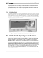
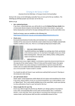
1
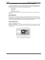
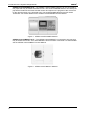
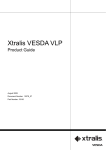
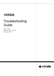
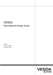
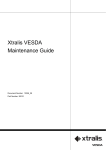
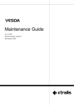
Introduction to the
System Design
Manual
September 2007
Document Number: 10270_05
Part: 30003
Introduction to the System Design Manual
ii
VESDA®
VESDA®
Introduction to the System Design Manual
Intellectual Property and Copyright
This document includes registered and unregistered trademarks. All trademarks displayed are the trademarks of their respective owners.
Your use of this document does not constitute or create a licence or any other right to use the name and/or trademark and/or label.
This document is subject to copyright owned by Xtralis AG (“Xtralis”). You agree not to copy, communicate to the public, adapt, distribute,
transfer, sell, modify or publish any contents of this document without the express prior written consent of Xtralis.
Disclaimer
The contents of this document is provided on an “as is” basis. No representation or warranty (either express or implied) is made as to the
completeness, accuracy or reliability of the contents of this document. The manufacturer reserves the right to change designs or
specifications without obligation and without further notice. Except as otherwise provided, all warranties, express or implied, including
without limitation any implied warranties of merchantability and fitness for a particular purpose are expressly excluded.
General Warning
This product must only be installed, configured and used strictly in accordance with the General Terms and Conditions, User Manual and
product documents available from Xtralis. All proper health and safety precautions must be taken during the installation, commissioning
and maintenance of the product. The system should not be connected to a power source until all the components have been installed.
Proper safety precautions must be taken during tests and maintenance of the products when these are still connected to the power source.
Failure to do so or tampering with the electronics inside the products can result in an electric shock causing injury or death and may cause
equipment damage. Xtralis is not responsible and cannot be held accountable for any liability that may arise due to improper use of the
equipment and/or failure to take proper precautions. Only persons trained through an Xtralis accredited training course can install, test and
maintain the system.
Liability
You agree to install, configure and use the products strictly in accordance with the User Manual and product documents available from
Xtralis.
Xtralis is not liable to you or any other person for incidental, indirect, or consequential loss, expense or damages of any kind including
without limitation, loss of business, loss of profits or loss of data arising out of your use of the products. Without limiting this general
disclaimer the following specific warnings and disclaimers also apply:
Fitness for Purpose
You agree that you have been provided with a reasonable opportunity to appraise the products and have made your own independent
assessment of the fitness or suitability of the products for your purpose. You acknowledge that you have not relied on any oral or written
information, representation or advice given by or on behalf of Xtralis or its representatives.
Total Liability
To the fullest extent permitted by law that any limitation or exclusion cannot apply, the total liability of Xtralis in relation to the products is
limited to:
(i) in the case of services, the cost of having the services supplied again; or
(ii) in the case of goods, the lowest cost of replacing the goods, acquiring equivalent goods or having the goods repaired.
Indemnification
You agree to fully indemnify and hold Xtralis harmless for any claim, cost, demand or damage (including legal costs on a full indemnity
basis) incurred or which may be incurred arising from your use of the products.
Miscellaneous
If any provision outlined above is found to be invalid or unenforceable by a court of law, such invalidity or unenforceability will not affect the
remainder which will continue in full force and effect. All rights not expressly granted are reserved.
Document Conventions
The following typographic conventions are used in this document.
Convention
Description
Bold
Used to denote: emphasis
Used for names of menus, menu options, toolbar buttons
Italics
Used to denote: references to other parts of this document or
other documents. Used for the result of an action.
The following icons are used in this document
Convention
Description
Caution: This icon is used to indicate that there is a danger to
equipment. The danger could be loss of data, physical damage,
or permanent corruption of configuration details.
Warning: This icon is used to indicate that there is a danger of
electric shock. This may lead to death or permanent injury.
iii
VESDA®
Introduction to the System Design Manual
Warning: This icon is used to indicate that there is a danger of
inhaling dangerous substances. This may lead to death or
permanent injury.
Contact Us
The Americas
+1 781 740 2223
Asia
+8 52 2297 2438
Australia and New Zealand
+61 3 9936 7000
Continental Europe
+41 55 285 99 99
UK and the Middle East
+44 1442 242 330
www.xtralis.com
Codes and Standards Information for Air Sampling Smoke Detection
We strongly recommend that this document is read in conjunction with the appropriate local codes and standards for smoke detection and
electrical connections. This document contains generic product information and some sections may not comply with all local codes and
standards. In these cases, the local codes and standards must take precedence. The information below was correct at time of printing but
may now be out of date, check with your local codes, standards and listings for the current restrictions.
FCC Compliance Statement
This equipment has been tested and found to comply with the limits for a Class B digital device, pursuant to part 15 of the FCC Rules.
These limits are designed to provide reasonable protection against harmful interference in a residential installation. This equipment
generates, uses and can radiate radio frequency energy and, if not installed and used in accordance with the instruction, may cause
harmful interference to radio communications. However, there is no guarantee that interference will not occur in a particular installation. If
this equipment does cause harmful interference to radio or television reception, the user is encouraged to try to correct the interference by
one or more of the following measures; re-orientate or relocate the receiving antenna, increase the separation between the equipment and
receiver, connect the equipment to a power outlet which is on a different power circuit to the receiver or consult the dealer or an
experienced radio/television technician for help.
FDA
This VESDA product incorporates a laser device and is classified as a Class 1 laser product that complies with FDA regulations 21 CFR
1040.10. The laser is housed in a sealed detector chamber and contains no serviceable parts. The laser emits invisible light and can be
hazardous if viewed with the naked eye. Under no circumstances should the detector chamber be opened.
FM Hazardous Applications
3611 Hazardous Approval Warning: Exposure to some chemicals may degrade the sealing of relays used on the detector. Relays used on
the detector are marked “TX2-5V”, “G6S-2-5V” or “EC2-5NU”.
VESDA detectors must not be connected or disconnected to a PC while the equipment is powered in an FM Division 2 hazardous
(classified) location (defined by FM 3611).
FM Approved Applications
The product must be powered from VPS-100US-120, VPS-100US-220 or VPS-220 only.
ONORM F3014
ONORM F3014, transport times for all tubes (including capillaries) must not exceed 60 seconds from any hole. This means that the predesigned pipe networks that include capillaries cannot be used.
AS1603.8
The performance of this product is dependent upon the configuration of the pipe network. Any extensions or modifications to the pipe
network may cause the product to stop working correctly. You must check that ASPIRE2 approves alterations before making any changes.
ASPIRE2 is available from your VESDA ASD distributor.
AS1851.1 2005
Maintenance Standards. Wherever this document and the AS1851.1 differ, AS1851.1 should be followed in preference to this document.
European Installations
The product must use a power supply conforming to EN54: Part 4.
Document Number:10270_05
Part Number: 30003
iv
VESDA®
Introduction to the System Design Manual
Contents
Scope ................................................................................................................................................1
Introduction .....................................................................................................................................1
Introduction to Aspirating Smoke Detection ................................................................................1
Introduction to Obscuration ...........................................................................................................2
Introduction to the VESDA Laser System .....................................................................................3
Pipe Network ...........................................................................................................................3
Laser Detectors .......................................................................................................................3
VESDA PC Software ...............................................................................................................5
Communications Network .......................................................................................................6
Connecting the VESDA Systems to External Systems ...........................................................6
Approvals ................................................................................................................................6
vii
Introduction to the System Design Manual
viii
VESDA®
VESDA®
Introduction to the System Design Manual
1.1 Scope
The System Design Manual provides an overview of the VESDA Laser Detection Systems. It
briefly explains concepts of Aspirating Smoke Detection and Smoke Obscuration.
This manual is written for those involved with the management and purchase of VESDA Laser
systems, consultants, specifiers and any one requiring an overview of the VESDA Laser
Detection Systems.
1.2 Introduction
The VESDA Laser System is an Aspirating Smoke Detection (ASD) System capable of detecting
smoke at low obscuration levels. This enabling detection of smoke at the incipient stage. VESDA
Laser Systems are successfully operating in applications ranging from ultra clean to harsh dirty
environments. The laser detectors have a variety of alarm levels. The thresholds for each alarm
level can be set to suit specific site conditions.
Figure 1 - Detectors sensitivity to detect smoke at various stages of a Fire
1.3 Introduction to Aspirating Smoke Detection
An Aspirating Smoke Detection System such as the VESDA Laser System, incorporates a
network of pipes with sampling holes continuously collecting air samples from the area being
protected. The sample air in the pipe network is drawn to the detector by a high efficiency
aspirator. The detector can detect minute concentrations of smoke, this is expressed as % obs
per meter or foot.
The success of an ASD system is dependent upon the smoke reaching the sampling holes and
being efficiently transported to a detector. A well designed pipe network takes into account the
natural and mechanically induced airflows within a customer site to ensure that air travels in the
direction of the sampling holes. The length of the pipe and the number of changes in direction of
the pipe will impact on the efficiency of an ASD System. Refer to the VESDA Pipe Network
Design, Pipe Network Installation and the ASPIRE2 User Guide for information on proper pipe
network design and installation.
1
VESDA®
Introduction to the System Design Manual
The versatility of the VESDA Aspirating Smoke Detection System means that it can be
successfully used in a diverse range of industry sectors and application environments. For
information on designing systems to meet the requirements of a specific application environment
contact your nearest VESDA Laser Detector Sales Office for copies of the Application Design
Guides.
1.4 Introduction to Obscuration
Smoke obscuration is the effect of smoke on visibility. It is the most widely accepted measure for
expressing the concentration of smoke and refers to the percentage of light that is blocked, or
obscured over a specified length (meter/foot). Increase in obscuration levels decreases visibility,
hence an obscuration of 10% obs/m (3.13% obs/ft.) will reduce visibility to 90%.
Typically pure oxygen has an obscuration rate of 0% obs/m (0% obs/ft.). At 0.01% obs/m
(0.003% obs/ft.) visibility levels are in the order of approximately 40 Km.
Incipient smoke, invisible to the naked eye in ordinary conditions has an obscuration range of
0.1% obs/m to 1% obs/m (0.03125% obs/ft. to 0.3125% obs/ft.). The figure below shows the
relationship between increase in obscuration and decrease in visibility. Obscuration is used to
define the sensitivity level of a smoke detector. The alarm sensitivity range for VESDA laser
detectors can begin at 0.005% obs/m (0.0015% obs/ft.), allowing detection of smoke at the
incipient stage from overheating wires or equipment.
3.3%/m
1%/ft
6.6%/m
2%/ft
10%/m
3.125%/ft
13%/m
4%ft
Figure 2 - Relationship between increase in obscuration and decrease in
visibility
2
VESDA®
Introduction to the System Design Manual
1.5 Introduction to the VESDA Laser System
The VESDA Laser System incorporates a network of pipes, detectors and supporting devices,
and a communications network. It is a versatile modular system that can be designed to meet
site specific requirements. The system can be broadly divided into:
•
•
•
•
Pipe Network
Laser Detectors
Software
Communications Network
The System Design Manual also covers topics such as Commissioning, Troubleshooting and
Accessories.
Pipe Network
Each detector is connected to a pipe network. The pipe network collects air samples through
sampling holes from a designated protected area and transports the sample air to the detector.
The VESDA Pipe Network Design Guide and the VESDA Pipe Network Installation Guide explain
in detail the design and installation requirements for an efficient pipe network.
Laser Detectors
There are four standard detectors:
VESDA LaserPLUS (VLP) - The VESDA LaserPLUS detector can be connected to four pipes,
each of these can be further branched into two. For further details see the VESDA LaserPLUS
Product Manual.
Figure 3 - VESDA LaserPLUS Detector
3
Introduction to the System Design Manual
VESDA®
VESDA LaserSCANNER (VLS) - The VESDA LaserSCANNER Detector can be connected to
four pipes that may be further branched into two. The Laser SCANNER Detector can identify the
pipe which introduces the smoke and will monitor and report on the progress of the occurrence
for the relevant sector in the protected area. The LaserSCANNER Detector has four Alarm
Thresholds. For further details see the VESDA LaserSCANNER Product Manual.
Figure 4 - VESDA LaserSCANNER Detector
VESDA LaserCOMPACT (VLC) - The VESDA LaserCOMPACT is connected to one pipe that
may be branched into two. The LaserCOMPACT has three Alarm Thresholds. For further details
see the VESDA LaserCOMPACT Product Manual.
Figure 5 - VESDA LaserCOMPACT Detector
4
VESDA®
Introduction to the System Design Manual
VESDA LaserFOCUS (VLF) - The VESDA LaserFOCUS is connected to one pipe that comes
with a number of preconfigured pipe layouts. The LaserCOMPACT has four alarm thresholds.
For further details see the VESDA LaserFOCUS Product Manual.
Figure 6 - VESDA LaserFOCUS Detector
An aspirator in each detectors draws air through the pipe network into a pipe inlet manifold to a
two stage air filter cartridge. The two stage air filter cartridge filters the sampled air, which then
flows on to the laser chamber. Most of the filtered air sample is used to detect the presence of
smoke, the remaining air is used to protect the optical surfaces in the laser chamber. The laser
chamber can detect smoke at minute levels of obscuration. If smoke is detected it is reported
through the CPU card to the display assigned to the detector. Presence of smoke can also be
displayed on a LCD Programmer or through a VESDA PC Software. The detector can be
configured to raise alarms at different levels and/or report events through a Fire Alarm Control
Panel (FACP).
VESDA PC Software
VESDA PC Software has been developed to configure, manage and maintain a VESDA Laser
System. The software packages allow varying degree of functions to the System.
Communications Network
VESDA Laser System communicates over a fault tolerant, bidirectional VESDAnet
communications network. Each VESDA Laser Product in the system is connected to VESDAnet.
Details on VESDAnet can be found in the VESDA Communications Guide.
Figure 7 - An example of VESDAnet
5
Introduction to the System Design Manual
VESDA®
Connecting the VESDA Systems to External Systems
The VESDA Laser System can be integrated to external Fire Alarm Control Panels and other
building management systems to raise pre-alarm and alarm conditions, action automatic
emergency procedures, and shut down ventilation systems. It can also be integrated into an
automatic fire suppressant release system.
Approvals
VESDA Laser Products have been approved by all internationally recognized approvals
agencies. Following is a listing of the approvals received for some VESDA Laser Products:
•
•
•
•
•
•
•
•
•
•
•
•
•
UL - Underwriters Laboratories
SSL - Australia
CSIRO - Australia
FM - Factory Mutual
ULC - Underwriters Laboratories Canada
LPC - Loss Prevention Council - United Kingdom
VdS - Germany
NTC - Mainland China
CSFM - California State Fire Marshall
New York - MEA
AFNOR - France
SMA C-tick
CE Mark
For details on the approvals visit the VESDA web site at www.vesda.com
6
VESDA®
Introduction to the System Design Manual
Index
A
O
ASD .....................................................
Obscuration ..........................................
1
Aspirating Smoke Detection .................... 1
2
S
C
Software ...............................................
iv
Conventions ......................................... iii
V
D
VESDA LaserCOMPACT .........................
5
Contact Us ............................................
Detectors sensitivity ..............................
1
4
VESDA LaserFOCUS .............................. 5
VESDA LaserPLUS ................................ 3
VLC...................................................... 4
VLF ......................................................
5
VLP ...................................................... 3
7
Introduction to the System Design Manual
8
VESDA®