1
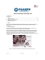
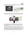
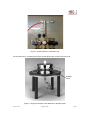
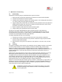
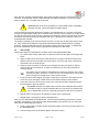
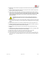
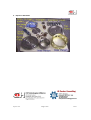
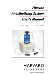
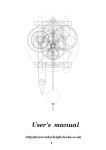
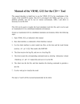
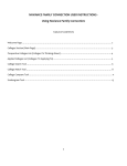
Modular Rodent Exposure Unit
Operation and Maintenance
User Manual
MODULAR RODENT EXPOSURE UNIT
CONTENTS
1
2
3
4
5
Scope .................................................................................................................................
General Description ............................................................................................................
Operation of the Exposure Unit ...........................................................................................
Maintenance and Cleaning ..................................................................................................
Exposure Unit Parts .............................................................................................................
2
2
5
6
9
1. Scope
This section of the ONARES User Manual describes the operation and maintenance methods for
the CH Technologies (Jaeger-NYU) Modular Nose-Only Directed-Flow Rodent Inhalation
Exposure Unit.
2. General Description
The CH Technologies Nose-Only Directed-Flow Rodent Inhalation Exposure Unit is modular
system for nose-only exposure of mice, hamsters, rats, and guinea pigs.
The modular exposure unit consists of stackable exposure tiers (Figure 1) plus top and bottom
sections or plates for introduction and exhaust of test article. Each tier has 12 exposure ports
which can be used for exposing up to 12 animals or sampling of test atmosphere. Each tier is
made of an inner plenum and an outer plenum that are connected to each other through
rectangular trumpets (tubes) and connector cones. All parts (except O-ring seals) are constructed
of stainless steel.
Exposure Tier
Connector
Cone
Trumpet
Figure 1. Partial View of Exposure Tier Showing Trumpet and Connector Cone
Exposure Unit
Page 2 of 9
5/16/07
The test animals are confined in polycarbonate containment tubes (examples shown in Figure 2)
which are attached to the exposure ports by friction fit. Both sealed and vented containment tubes
are available for mice, hamsters, rats, and guinea pigs.
Vented Containment Tubes
Sealed Containment Tube
Figure 2. Examples of Animal Containment Tubes
Fresh test atmosphere is provided to each animal from the inner plenum and exhausted into the
space between the inner and the outer plenum (Figure 3). The test aerosol, gas, or vapor that
flows through the inner plenum is distributed uniformly to the test animals through the trumpet.
Exhaust (Upper swivel)
Connector cone
Trumpet
Outer plenum
Inner plenum
Fresh Aerosol
Exhaled Breath
Test article inlet (Bottom swivel)
Figure 3
The chamber is equipped with a bottom inlet section (plate) and a top exhaust section. Both
sections are designed to connect easily to other equipment through swivels. Venturi tubes to
measure the exposure unit inlet and exhaust flows may be included with the system. These
attach at the inlet and exhaust of the unit. The venturi tubes are attached to pressure gauges
which are calibrated to flow.
If vented tubes are used, the chamber should be operated at a slightly positive pressure (i.e., the
inlet flow should slightly exceed the exhaust flow) to assure that the test atmosphere is not diluted
by air entering the animal containment tube. However, operating the system at a positive
pressure may result in escape of test article from the exposure unit into the hood. If sealed animal
containment tubes are used, the exhaust flow should be slightly higher than the inlet flow of the
chamber. This will assure no escape of test article from the exposure unit. When the system is
run with sealed animal containment tubes, the exhaust section is equipped with an air inlet (small
filter) in order to make up for the flow difference between inlet and exhaust (Figure 4).
Exposure Unit
Page 3 of 9
5/16/07
Figure 4. Exhaust Section of Exposure Unit
The chamber sits on a rotating table (Figure 5) that allows easy access to all nose ports.
Rotating
Table
Figure 5. Single Tier Exposure Unit Mounted on Rotating Table
Exposure Unit
Page 4 of 9
5/16/07
3.
Operation of the Exposure Unit
3.1.
System Assembly
1. Refer to Section 4.3 for instructions on assembly of the exposure unit.
2. If inlet and exhaust flow venturi tubes are to be used, attach these to the inlet and
exhaust of the exposure unit making sure that the inlet venturi is on the inlet of the
exposure unit. Connect the venturi pressure tubes to the appropriate venturi tubes,
making sure that they are in the proper order. They are color coded.
3. Connect the supply air tubing to the inlet of the exposure unit.
4. Connect the exhaust air tubing to the exhaust of the exposure unit.
5. Turn on the Off Exposure Air to a flow of about 500 ml/min for each test animal and
sampler on the system. For a 24 port system, this amounts to a total off exposure air flow
of 12 L/min If use rate of test article is an issue, the flow rate can be reduced to 250
ml/min for mice only.
3.2.
Mounting Animals on Exposure Unit
1. Load animals into containment tubes and tighten pusher just tight enough to prevent the
animal from turning around in the tube. If the pusher is too tight, it will impede the
breathing of the animal.
!
WARNING: Do NOT mount containment tubes with animals onto the exposure
unit until Off-Exposure or Exposure Air has been turned on and adjusted to the
proper flow. To do so may result in suffocation of the animals.
2. Mount the containment tubes onto the exposure unit exposure ports by pushing them
slowly forward until the nose of the containment tube rests firmly against the internal wall
of the connecter cone.
!
!
WARNING: Do not use excessive force while pushing the tubes into the
connector cone as this may cause tubes to crack or may damage the O-rings.
WARNING: Make sure you plug all unused ports before starting exposure.
Keep all the ports plugged after cleaning the chamber until the next round of
exposure begins.
Test article (either gas or particulate) has been shown to be evenly distributed to all nose
ports of the exposure unit. Therefore, there is no specific recommendation of distribution
of animals if fewer than the total number of ports are to be used. However it is preferable
that the tubes be evenly spaced around the perimeter of the chamber. Any of the ports
may be used for taking grab samples or for on-line aerosol concentration monitoring and
temperature/relative humidity monitoring.
TIP
3.3.
Tip: When you expose the animals to aerosols, begin daily exposures with the
control group of animals and progress from low dose groups to high dose
groups. This exposure pattern limits cleaning of the exposure unit to only once
at the end of exposure of all animal groups.
Exposure Control
The exposure unit is operated from the control panel. Three flow meters and flow controllers on
the Flow Panel regulate the amount of air passing through the chamber and chamber pressure:
The Vaporizer Air, Dilution Air, and Off Exposure Air). For operation of the test article generation
devices, refer to the section of the manual pertaining to the particular generator being used.
Exposure Unit
Page 5 of 9
5/16/07
4. Maintenance and Cleaning
4.1.
Disassembly
Implement the following steps to disassemble the exposure chamber:
1. Disconnect the venturi tubes (if present) and swivels from inlet and exhaust plates.
2. Unscrew the exhaust tube from the top plate.
3. Carefully lift the exposure chamber from its resting place on the rotating table and place it
on a clean working surface prepared beforehand.
4. Apply the lifting tool provided with your toolkit around the perimeter of the outer plenum to
partially lift the top plate, then remove it by pulling it up with both hands. Use the same
procedure to remove the inner plenum cap.
5. Flip the chamber upside-down and remove the bottom plate.
6. Using the lifting tool, separate the tiers from each-other.
The tiers can be further disassembled into their constituent parts for deep cleaning or
maintenance purposes. However, this process requires specialized personnel and it is not
recommended to be performed on a routine basis. If a total disassembly is needed, please
consult the CH Technologies technical support staff first.
To totally disassemble the tiers do the following:
7. Unscrew the connector cones from their holes in the outer plenums of both tiers.
8. Unscrew all the trumpets from the inner plenums of both tiers using the special socket
wrench provided with the toolkit.
9. Remove all the O-rings from inner plenums, outer plenums, connector cones, and the
plates.
4.2.
Cleaning
The cleaning schedule of the exposure unit will depend on their utilization regimen. If the system
is used for vapor inhalation, it is not necessary to clean the chamber daily, but a thorough
cleaning should be performed before starting the exposure with a new/different test article.
However, if powders, liquid aerosols or cigarette smoke are used, cleaning is required at the end
of every exposure day. A thorough daily cleaning is particularly required after exposure to
cigarette smoke.
Cleaning with a mild soap solution in warm water is generally adequate. Depending on the test
article used, special solvents may be used in certain cases. Be sure that the O-rings are
compatible with any solvents used. Special chemical resistant O-rings are available from CH
Technologies. Clean the lumen of the trumpets with a cotton swab. Distilled water is a good
choice for the final rinse; warm tap water may work also. You must judge the success of your
cleaning/rinsing with your own QA/QC wipe tests or similar assessments.
While it is not recommended that chamber parts be cleaned in a dishwasher or cage washer, it is
possible to use such a procedure if you desire. However, if you opt for automatic cleaning, you
should first contact CH Technologies in order to establish appropriate guidelines for cleaning
under high pressure and hot water at alkaline pH.
!
Exposure Unit
WARNING! If automatic washing is not carried out properly, it may cause
mechanical damage and/or chemical corrosion to the sealing surfaces of
various system parts.
Page 6 of 9
5/16/07
Each time the chamber is disassembled, the threads should be cleaned, inspected for wear or
corrosion, and taped with Teflon or lubricated with the sealant materials; e.g. vacuum grease,
Teflon emulsion, etc., provided with your toolkit.
!
WARNING! Be aware of the possibility of cross threading when assembling
parts with threads. Check all threads for hidden debris.
O-rings should be inspected during each cleaning. The slightest tear or cut on the O-rings will
result in an inappropriate sealing of the chamber parts, and may result in leaking of the test article
into the air. Even when the O-rings don’t appear to be damaged, used O-rings should be changed
at frequent intervals because they deteriorate with time. Lubricate them as required when you
reassemble the chamber.
The cleaned chamber parts should be allowed to air dry or they may be dried with warm forced
air. They should be lubricated as required and reassembled with careful attention to sealing
surfaces. Pressure tests (leak checks) and system integrity should be verified. A detailed log
should be maintained with the cleaning schedule and results of the leak tests.
4.3.
Reassembly
Follow these steps to reassemble the chamber from a total disassembled state:
1. On a clean work surface, place the inner plenum inside the outer plenum and align their
holes.
2. Apply a small amount of lubricant to the threads of a trumpet, and with the help of the
special socket wrench provided, insert it through a connector hole in the outer plenum
and screw it into the inner plenum.
3. Using the same procedure, insert two more trumpets into the inner plenum, spaced
evenly around its circumference, to make sure that the inner and outer plenums are
correctly aligned.
TIP
The fingers may be needed to manipulate the trumpet into position and to begin
screwing it in place. However, once this is done, the socket wrench can be used
finish screwing the trumpet into the inner plenum quickly.
4. Insert two of the small, slightly more rigid O-rings into the grooves in the inside of three
connector cones and apply a small amount of lubrication directly to their threads.
5. Screw the connector cones into the holes in the outer plenum that are aligned with the
three trumpets in the inner plenum.
!
WARNING: Do NOT over tighten the connector cones! Simple hand pressure
is usually enough to properly assemble the unit. The amount of pressure that
can be applied with a wrench is generally greater than that which is required.
6. Repeat steps 2 through 5 for the remaining 9 ports of the exposure tier.
7. Repeat steps 1 through 6 for all other exposure tiers.
After you have assembled the individual tiers, continue with the following procedure to put the
exposure unit together. If you have not totally disassembled your exposure unit, you may start
here with the reassembling procedure:
8. Using a cotton swab, lubricate the top and bottom ridges of the inner and outer plenum of
the assembled tiers.
9. Lubricate the grooves in the bottom plate in the same manner.
Exposure Unit
Page 7 of 9
5/16/07
10. Remove any excess lubricant by wiping the mentioned surfaces with a paper towel or a
clean cloth.
11. Place one large O-ring into the groove in the outer plenum and a smaller O-ring into the
groove of the inner plenum on both tiers.
12. Using another cotton swab, apply a small amount of lubrication to the surface of the Oring of one of the tiers to allow the rings to rotate freely with respect to each other. Gently
rest the first tier in the proper grooves in the base plate WITHOUT pushing down. Rotate
the tier several times while resting it on the grooves to assure that both surfaces are
properly lubricated.
!
WARNING: Do not push the tier down onto the bottom plate without first
rotating it several times. If you do so, you will risk cutting or pinching the Orings.
13. Next, firmly press the tier down into the bottom plate, making sure that the O-rings remain
in the groove to avoid cutting it. A click should be heard, indicating that the tier is properly
seated.
14. Repeat steps 8 through 13 to connect the subsequent tiers on top of the previous one.
15. Applying the laboratory grade silicone sealant with a cotton swab, lubricate the portion of
the inner plenum cap that will connect to the inner plenum.
16. Next, place the O-ring in the groove in the inner plenum cap and lubricate the O-ring
surface.
17. Position the cap in place and press down firmly until the click is heard. Once again, make
sure that the O-ring remains in the groove to avoid cutting it.
18. Apply silicone sealant to the ridge of the top plate with another cotton swab.
19. Place the second large O-ring into the groove in the top plate's ridge.
20. Lubricate the surface of the O-ring and remove the excess. Place in proper position and
press down firmly, once again making sure not to cut the O-ring. The click will indicate a
secure fit.
Exposure Unit
Page 8 of 9
5/16/07
5. Exposure Unit Parts
Exposure Unit
Page 9 of 9
5/16/07