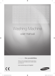
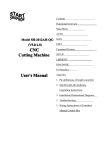
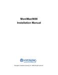
1
www.bgareballing.ro
Manual GM490
1. BGA Rework Station Setting Up
2. BGA Rework Station Safety Precautions
3. BGA Rework Station Main Specification
1
www.bgareballing.ro
4. BGA Rework Station Operation Steps
5. BGA Rework Station Touch Screen Operation
6. BGA Rework Station Handling Precautions
Enclose: Packing List
1. BGA Rework Station Setting Up
a. Installation Location
In order to ensure the service life of rework station, the installation must meet
the following conditions:
1.
2.
3.
4.
5.
6.
7.
8.
Away from flammable, explosive materials
Don’t spilled by water and other liquid
Well-ventilated and Dry Place
Stable, Smooth, less vibrate place
Little dusty place
Don’t put anything on control box
Away from the place affected by the direct flow of air condition, heater and fan
For upper part easy move and turn, More than 30cm Match at the back of rework station
b. Power supply requirements:
Use small fluctuant voltage power supply.
Voltage: 220V±10
Frequency: 50Hz±3
2. BGA Rework Station Safety Precautions
1. Don’t blow the rework station directly when it work, or will lead the negative differential
of the surface of the heating plate, burned the parts
2. After starting up, high temperature heat area cannot contact anything directly, or may
cause fire or explosion, PCB board should be put on the PCB board support
3. Don’t shake rework station, move lightly.
2
www.bgareballing.ro
4. After starting up, do not use flammable spray, liquid gas.
5. Don’t try to redo the rework station, or will cause fire or electric shock.
6. There are high-voltage parts in electric box, don’t take part or remove without
permission
7. If there is metallic object or liquid fall into rework station, shut off the power immediately,
unplug power line, and completely remove the object and dirt after the station get cooling. If
having residue, will emit odor after rework.
8. When rework station abnormal heating-up or smoke, shut off the power immediately,
notify the technician repair, partly shut off power when move electric box or machine, hold
the plug when unplug the wire, otherwise will cause poor contact, cannot work.
9. Shut off the power when stop use.
10. Rework station do not press or run over line or communication cable of other
equipments power otherwise may cause equipment malfunction or cause fire or electric
shock
11. Before operating the rework station, must read this introduction manual carefully.
3. BGA Rework Station Main Specification
3
www.bgareballing.ro
4
www.bgareballing.ro
NO
Name
1
Up-Down Adjustment
For adjusting up and
Handle
down the top heater
Front-Back
For adjusting front and
Adjustment Handle
back the top heater
Top Heater
For adjusting the fan
Adjustment
speed of the top heater
Cooling Fan
For cooling after
2
3
4
Function
Method
Remark
Set by touch screen
heating
5
6
7
Temp. sensor
Touch Screen
LED Button
For checking the real
Plug in the
temperature of the PCB
temperature test wire
For operating the
Look the follow user
machine
manual
For turning on and off
the LED
8
Knob Screw
For locking the platform
9
PCB Supporting Pole
For supporting the PCB
10
LED Light
For lighting
11
Top Heater
For heating the chipset
Set by touch screen
Main parameter:
1. Total Power:
4300W
2. Top heater:
1000W
3. Bottom heater:
2nd heater 1000W, 3rd Infrared Radiation heater 2300W
4. Power supply:
AC 220V/230V
5. Dimensions:
L600mmⅹW600mmⅹH610mm
5
50/60HZ
www.bgareballing.ro
6. Temperature Control:
High-precision K-type thermocouple
7. Positioning:
V-shaped slot PCB positioning
8. PCB size:
Max PCB size 450*500mm; Min PCB size 40*40mm
9. Electrical material:
Highly sensitive temperature control/Touch screen/PLC
10. Machine Weight:
45kg
Description:
1. This product adopt 7.0” HD touch screen Human–Machine Interaction(HMI), PLC
Control, real-time display five temperature curve, temperature precision be controlled in ±
degree.
2. 6 section temperature controls, can further refine the temperature of each solder
segment, to better ensure the welding effect.
3. Can save 0-49 group of temperature curve setting, analyze the curve and change the
setting on touch screen anytime.
4. There are 3 heating zones to heating separately, can control multi-group, multi-section
temperature in the 3 heating zones at same time, ensure achieve the best welding effect in
different heating zones. Heating temperature, time, slope, cooling, vacuum, all can be set
on HMI.
5. Select high-precision K-Type thermocouple closed-loop control, detect temperature
precisely through the external temperature testing interface.
6. Have alarm function after finish unsolder, have over-temperature protection circuit
around the whole machine, stop heating and alarm when abnormal over-temperature
7. Use High Cross-flow Fan cool PCB board promptly, in case the deformation of PCB
board, ensure the welding effect.
7. Use V Shape groove address the PCB, Flexible removable have the function of protect
PCB
8. For large thermal capacity PCB and other high temperature requirements, both
lead-free BGA/CSP and column BGA can deal with easily.
9. Hot air nozzles can 360 degree rotation, easy to replace. With a variety size of hot air
6
www.bgareballing.ro
nozzle, special requirements can be customized.
4. BGA Rework Station Operation Steps
1. Pre-heating:
Pre-heat PCB and BGA before rework, in case of bursting while rework, temperature of
constant temperature oven is generally set at 80 ℃ -100 ℃, time often are 12-24hours.
2. Disassembly:
Put PCB on the position support of rework station, select the appropriate hot air reflow
nozzle, set proper welding temperature curve, pull the start switch, when procedure run
over, move the hot air manually, use vacuum suction pen remove BGA.
3. Clean the welding:
Cleaning of PCB and BGA welding pad, one is use the suction tin line tow to same
level, another is use soldering iron drag smooth directly. It is best remove soldering tin in a
short time after remove BGA, while BGA not cooling totally, less damage of temperature
difference to welding pad; Use soldering flux in the process of removing solder, can
improve the solder activity, conducive to the removal of solder. Especially pay attention to
do not damage the welding pad of PCB, for ensuring reliability of BGA welding, try to use
some strong volatile solvent, washer, industrial alcohol during clean the remain solder
paste on solder pad.
4. BGA REBALLING
Evenly coated solder paste on BGA pad with a brush, select the corresponding
REBALLING steel mesh, use REBALLING STATION plant BGA tin sweat on corresponding
BGA pad.
5. BGA Tin Sweat Welding
Heating the bottom of Tin sweat station and rework station heating zone, solder the tin
sweat on BGA pad
6. Spread soldering flux
Spread a layer of solder flux on PCB pad with a brush, too much will cause soldering
7
www.bgareballing.ro
together, on the other hand, too less will cause missing soldering, thus for clean the dirt on
BGA tin sweat, enhance soldering effect, solder paste must be spread appropriately.
7. Mount
Mount BGA on PCB, when counterpoint by hand, use silk screen print frame line helps
counterpoint, confirming whether mount BGA in counterpoint by hand touch feeling of
surface of Tim Sweat and soldering pad.
8. Welding
Put PCB on the position support of rework station, select the appropriate hot air reflow
nozzle, set proper welding temperature curve, start heating inching switch, run soldering
procedure, stop running, front BGA cooling fan start cool BGA, improve hot air point, make
hot air nozzle above on surface of BGA 8-10mm. and keep cooling 30-40 seconds, or after
the start switch light power off, move hot air head, and then take away the PCB board from
bottom heating area position stably.
a. Missing Solder; because of manually counterpoint will make deviation between chips
and solder pad, Tension of tin sweat surface will make a process of correct the place
between BGA chips and pad automatically.
Because of uneven heating, leading the
chip fall unevenly, if stopping reflowing now, the chip will not fall normally, resulting in
non-co planarity phenomenon and then cause missing solder and cold solder, so need
extend the time of temperature of third and forth section THERMATICS, our enhance
the pre-heating temperature at bottom, melt tin sweat and fall evenly.
b. Short Circuit: The tin sweat is liquid when get melting point, the extension and
support function of tin sweat support will be damaged when suffer over-time, over heat
temperature or over press, and then lead short circuit because of chip fall on the PCB
pad completely while reflowing, Hence, we need decrease temperature and time of the
third and forth heating section, or decrease the preheating temperature at bottom.
Note: Will appear small quantity ozone when reword station using, in order to
ensure a comfortable, healthy and safe operating environment, please keep
good air circulation.
8
www.bgareballing.ro
5. BGA Rework Station Touch Screen Operation
Operation Introduction:
A. Open the control power supply, rework station is powered. You will see like the
below interface.
And then will appear top target temperature, top actual temperate, bottom actual
temperature, actual thermostatic temperature of the third THERMATIC (preheating
temperature at bottom), outer actual temperature from up to down at the right side of the
touch screen.
9
www.bgareballing.ro
Curves on image are: Tope target temperature (blue), top target actual temperature
(red), bottom actual temperature (green), infrared actual temperature (purple), out tested
actual temperature
Click
enter into each asked specification of running after start heating
These specifications are the target temperature, holding temperature time, heating-up
speed
Second is the unit of heating-up speed, three THERMATIC of Top, infrared can set 6
section heating-up, 6section temperature-holding curve model, at this interface, also can
modify the specifications, but this specification will not be saved in inner of procedure, only
be used in the heating curve after start at this specification. To save, please read formula
setting content!
Click
Click
, return to curve interface
, the whole machine get into start heating, the running heating
curve is specification as above described specification, meantime clean out last curve show
on screen.
Under normal operation, when top target temperature and heating speed is zero, the
whole process finished, machine stop work, hear Roar sound., if have set cooling and
vacuum state in cooling vacuum interface, the output of cooling and vacuum will run.
Click
,when running, the whole machine will stop.
is the
current state
Click
,when running, this button will shine, notify that the whole machine
go into temperature-holding state, the three group of heating temperature output will remain
10
www.bgareballing.ro
at present temperature, running in constant temperature, till to re-click
return to normal heating state.
Click
1. Click
2.
Clock
popup function select interface
return to Chinese-English interface
popup “enter code “window
11
,
www.bgareballing.ro
The default pass word is 8888, after enter the code, and enter into PID specification
setting;
All specifications have been set before leave factory, no need change
3. Click
will appear follow image:
12
www.bgareballing.ro
Modify and save temperature curve often used
Set the heating temperature, constant temperature time, heating speed required by
production craft, this product can store the temperature curve up to 50 groups. Save
various production craft specifications in system, call it directly when meet different
production craft.
Means the Formula stored in system, because the heating temperature is different
while different products using. We could save different specification in different formula.
When change the product, do not modify the specification much, just click call the
corresponding formula
Click the Enter key numerical value at the pop-up
Enter the modified data, press
,
specification of Three THERMATICS, click
Finished setting Temperature
then all specification set just now have
13
www.bgareballing.ro
stored under the name(serial number) of present formula.
. Also can get the asked temperature curve directly through
(The formula noted)
two buttons.
(0-49) enter corresponding serial NO. Click
restart
the running temperature curve of heating
Or save the modified temperature specification in present interface through
4. Click
ot following interface:
Heating finished, System will run cooling and vacuum as
(Counting by second), or manually control cooling and vacuum state by
14
.
www.bgareballing.ro
after went into manual, whether heating or not, vacuum suction always worked, click
cooling manual button, only stop heating, then output, heating start, output stop, for having
enough time take away the suction pen, suggest that when remove chip, set the cooling to
zero.
This machine can real-time monitor the rotating speed of cooling fan of up-down hot air,
also can set the min rotating speed. Fan stop work or rotating speed less than set data
during heating, and up-down hot air data high than 300 degree, system will stop heating
immediately, alarm at same time, whole machine turn to cooling state, will show where is
the trouble on main interface, can help worker find the trouble in a short time.
Caution!
While alarm due to trouble, all functional button will be locked! It cannot work
still after deal with the trouble, power off.
Temperature specification often used as following:
Lead solder temperature curve
41*41 BGA Solder temperatures setting:
15
www.bgareballing.ro
Top
Heating
Constant
Temperat
ure
Time
Bottom
Heating
Constant
Temperat
ure
Time
Infrared
Time
Constant
Temperat
ure
Time
Slope
38*38
Preheating
section
Temperature-h
olding section
Heating-up
section
Solder
section
1
160
185
210
220
30
30
35
40
165
195
215
230
30
30
35
60
110
120
130
140
30
30
35
60
2.0
2.0
2.0
2.0
BGA Solder Temperature Setting:
16
Solder
section
2
Temperaturedrop section
www.bgareballing.ro
Top
Heating
Constant
Temperat
ure
Time
Bottom
Heating
Constant
Temperat
ure
Time
Infrared
Time
Constant
Temperat
ure
Time
Slope
31*31
Preheatin
g section
Temperatureholding
section
Heating-up
section
Solder
section
1
160
185
210
225
30
30
35
40
165
190
215
230
30
30
35
40
110
120
130
140
30
30
35
40
2
2
2
2
Temperaturedrop section
BGA Solder Temperature Setting:
Preheatin
g section
Top
Heating
Constant
Temperat
ure
Time
Bottom
Heating
Constant
Temperat
ure
Time
Infrared
Time
Constant
Temperat
ure
Time
Slope
Solder
section
2
Temperature-h Heating-u
olding section p section
Solder
sectio
n1
160
180
200
215
30
30
35
40
160
180
200
215
30
30
35
40
110
120
130
140
30
30
35
40
2
2
2
2
17
Solder
section
2
Temperaturedrop section
www.bgareballing.ro
Above is reference for lead BGA temperature Curve
Lead-free temperature curve solder
41*41
Top
Heating
Constant
Temperat
ure
Time
Bottom
Heating
Constant
Temperat
ure
Time
Infrared
Time
Constant
Temperat
ure
Time
Slope
BGA Solder temperatures setting:
Preheating
section
Temperature-h
olding section
Heating-up
section
Solder
section
1
Solder
section
2
165
190
225
245
255
30
30
35
55
25
165
190
225
245
255
30
30
35
55
25
120
130
140
150
160
30
30
35
55
25
2
2
2
2
2
18
Temperaturedrop section
www.bgareballing.ro
38*38 BGA Solder temperatures setting:
Top
Heating
Constant
Temperat
ure
Time
Bottom
Heating
Constant
Temperat
ure
Time
Infrared
Time
Constant
Temperat
ure
Time
Slope
Preheating
section
Temperature
-holding
section
Heating-up
section
Solder
section
1
Solder
section
2
165
190
225
245
250
30
30
35
45
25
165
190
225
245
250
30
30
35
45
25
120
130
140
150
160
30
30
35
45
25
2
2
2
2
2
19
Temperature
-drop
section
www.bgareballing.ro
31*31 BGA Solder Temperature Setting
Prehea
ting
section
Temperature
-holding
section
Heating
-up
section
Solder
section
1
Solder
section
2
165
190
220
240
245
30
30
35
40
20
165
190
220
240
245
30
30
35
40
20
120
130
140
150
160
30
30
35
40
20
2
2
2
2
2
Top
Heating
Constant
Temperatu
re
Time
Bottom
Heating
Constant
Temperatu
re
Time
Infrared
Time
Constant
Temperatu
re
Time
Slope
Temperature
-drop
section
Above is reference for lead-free BGA temperature Curve
If you want to dismantle BGA, it is enough to set the value of temperature-drop
section as 0.
6. BGA Rework Station Handling Precautions
1. Open repair station power switch, first check whether there is cold wind blowing in
the upper hot lips and lower hot lips. If no wind blowing out, don’t use the start switch,
20
www.bgareballing.ro
otherwise it will burn the up and bottom main heater; the bottom of the all infrared heating
area is controlled with the switch. You can choose the bottom of the infrared heating area
according to the size of PCB board.
2. Rework different BGA, it needs to set different temperature curve, the maximum
temperature of each segment setting cannot exceed 300 ℃. When rework with lead-free,
one can set according to welding temperature curve reference of BGA solder beads.
3. When dismantle BGA, first transfer cooling fan and vacuum gear to the automatic
gear, when the temperature curve operation is end, the buzzer alarms automatically, at this
time quickly suck away BGA from the PCB board with vacuum suction pen, and then
remove PCB board holder from the location grid.
4. While soldering the BGA, first transfer cooling fan is to the manual gear, turn off the
vacuum. When the temperature curve operation is end, buzzer alarms automatically, the
cooling fan starts to cool the heating area BGA and the down heating zone. Hot air chills
cold wind at the same time. Then upgrade the main heater at the top, so that the bottom of
hot air nozzle is 3 ~ 5MM up to the upper surface of BGA, and keep cool for 30 to 40
seconds, or remove the main heater after turning off the start switch lights, , then remove
the PCB board from the rack pan.
5. Before BGA installation, you must check whether the PCB board by chip and BGA
solder ball pad is good; BGA chip must be carried out by visual inspection after soldering. If
something is unusual, one should stop the installation of BGA and test the temperature, one
cannot weld it before it is adjusted properly, otherwise it may damage the BGA or the PCB
board.
6. The surface of the machine should be cleaned regularly; in particular, keep the clean
of Infrared heating board to prevent dirt accumulating in the top which will affect the normal
heat radiation, resulting in poor welding quality, and shortening the life of infrared heater.
If the heating unit is burned due to this reason, the Company will not be responsible for
free replacement!
Concluding Remarks
In production areas of electronic products, especially computer and communications
electronics products, the component is developing to the miniaturization, multi-function,
21
www.bgareballing.ro
green orientation, various packaging technologies continue to emerge, BGA / CSP is the
mainstream of packaging technology nowadays.
To meet the rapidly growing demand of circuit assembly of BGA devices,
manufacturers need to choose safer, more convenient and more efficient assembly and
rework equipment technology.
Enclose Packing List:
No.
Item
Description
QTY
Remark
GM490
1
Touch
screen
CE
1
BGA Rework Station
2
Vacuum pen
1
3
Vacuum sucker
3
4
Omega
Thermometric wire
1
5
User manual
1
6
Hot air nozzle
7
Abnormity clip
6
8
Plum knob sticks
6
9
Supporting pole
2
10
Supporting screws
8
30*30-48*51
22
5
CE