1
Connecting the Sockets
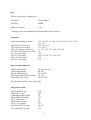
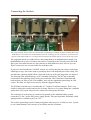
The top four output sockets. These are Switchcraft 112APCX types normally used for soldering direct into
PCBs but here used with wires and heatshrink. Note the earth lugs of each socket have been connected
together with 0.9mm solid core wire and connected back to the board with one wire from the top socket.
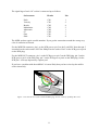
The suggested layout uses eight sockets, and wiring them up is straightforward enough. Use
multistrand hook up wire to connect each socket’s signal lug to the relevant pad on the PCB.
Keep your wires short but not too short and use as many different colour wires as you can.
There is no need to use screened cable for such short runs.
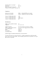
If you have used Switchcraft 112APCX sockets you will see that they have three connections
called lugs or tags. One is the earth or ground tag next to the diagonal part of the casing. The
second is the signal tag which will be connected to the tip of the jack plug when it is inserted.
The third tag is the normalised tag, or NC (normally closed) lug. The NC lug is internally
connected to the signal tag when a jack is not connected. This connection is automatically
broken when you insert a jack. The midiDAC uses only the signal and ground lugs on each
socket. The other two lugs are not used at all in the suggested layout.
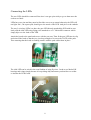
The PCB has been laid out to accommodate 0.1” headers for all interconnects. This is very
useful for taking the board in and out for servicing. However, for a panel fitting into a modular
synth, there is no reason why you can’t solder wires directly into the holes.
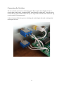
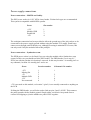
The earth lugs of each socket are connected to ground via the standard Oakley ground
connection, ie. Pin 3 on the PSU power supply header. This special ground, sometimes called
'panel ground' is available at pin 5 on CN1.
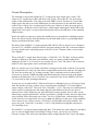
The sockets' ground lugs can be connected together with one piece of solid core wire. I prefer
to use 0.9mm diameter wire because of its stiffness and low resistance.
10