1
Allen-Bradley
2-D Hand-Held
Bar Code
Scanners
(Cat. No. 2755-HTG-4)
Bar Code
Programming
Guide
Important User Information
The illustrations, charts, sample programs and layout examples
shown in this guide are intended solely for purposes of example.
Since there are many variables and requirements associated with any
particular installation, Allen-Bradley does not assume responsibility
or liability (to include intellectual property liability) for actual use
based upon the examples shown in this publication.
Allen-Bradley publication SGI-1.1, Safety Guidelines for the
Application, Installation, and Maintenance of Solid-State Control
(available from your local Allen-Bradley office), describes some
important differences between solid-state equipment and
electromechanical devices that should be taken into consideration
when applying products such as those described in this publication.
Reproduction of the contents of this copyrighted publication, in
whole or in part, without written permission of Allen-Bradley
Company, Inc., is prohibited.
Throughout this manual we use notes to make you aware of safety
considerations:
!
ATTENTION: Identifies information about practices
or circumstances that can lead to personal injury or
death, property damage or economic loss.
Attention statements help you to:
• identify a hazard
• avoid the hazard
• recognize the consequences
Important:
Identifies information that is critical for successful
application and understanding of the product.
Table of Contents
Preface
Configuration Bar Code Symbols . . . . . . . . . . . . . . . . . . . . . . . .
How to Use this Guide . . . . . . . . . . . . . . . . . . . . . . . . . . . . . . . .
Chapter 1
P–1
P–2
Scanner Configuration
Set Default Parameters . . . . . . . . . . . . . . . . . . . . . . . . . . . . . . .
Select the Symbologies You Want to Enable or Disable . . . . . . . .
Select Code 39 Options . . . . . . . . . . . . . . . . . . . . . . . . . . . . . . .
Transmit UPC-A / UPC-E Check Digit . . . . . . . . . . . . . . . . . . . . .
Convert UPC-E to UPC-A . . . . . . . . . . . . . . . . . . . . . . . . . . . . .
Decode UPC/EAN Supplements . . . . . . . . . . . . . . . . . . . . . . . . .
Convert EAN-8 to EAN-13 . . . . . . . . . . . . . . . . . . . . . . . . . . . . .
Select UPC-A Preamble . . . . . . . . . . . . . . . . . . . . . . . . . . . . . .
Select UPC-E Preamble . . . . . . . . . . . . . . . . . . . . . . . . . . . . . .
Select Code 39 – Code Lengths . . . . . . . . . . . . . . . . . . . . . . . . .
Select Codabar Code Lengths . . . . . . . . . . . . . . . . . . . . . . . . . .
Select Interleaved 2 of 5 Code Lengths . . . . . . . . . . . . . . . . . . . .
Select Prefix / Suffix Options . . . . . . . . . . . . . . . . . . . . . . . . . . .
Data Transmission Format . . . . . . . . . . . . . . . . . . . . . . . . . . . . .
Transmit No-Read Message . . . . . . . . . . . . . . . . . . . . . . . . . . . .
Transmit LRC Checksum . . . . . . . . . . . . . . . . . . . . . . . . . . . . . .
Transmit Code ID Character . . . . . . . . . . . . . . . . . . . . . . . . . . . .
Beeper After Good Decode / Beeper Tone . . . . . . . . . . . . . . . . . .
Decode Buffering . . . . . . . . . . . . . . . . . . . . . . . . . . . . . . . . . . .
Pause Duration . . . . . . . . . . . . . . . . . . . . . . . . . . . . . . . . . . . . .
Decode Attempt Duration . . . . . . . . . . . . . . . . . . . . . . . . . . . . . .
Time Delay to Low Power Mode . . . . . . . . . . . . . . . . . . . . . . . . .
Timeout Between Decode Values, Same/Different Symbols . . . . .
Smart Raster . . . . . . . . . . . . . . . . . . . . . . . . . . . . . . . . . . . . . .
Hand-Held Options . . . . . . . . . . . . . . . . . . . . . . . . . . . . . . . . . .
1–1
1–3
1–6
1–7
1–7
1–8
1–8
1–9
1–9
1–10
1–11
1–12
1–14
1–16
1–17
1–17
1–18
1–19
1–19
1–20
1–20
1–22
1–22
1–24
1–24
Publication 2755-6.7
Publication 2755-6.7
toc–ii
Table of Contents
Chapter 2 RS-232 Synapse Cable
(Communication Setup)
RS-232 Synapse Cable Defaults . . . . . . . . . . . . . . . . . . . . . . . . 2–2
Fixed Format Hosts . . . . . . . . . . . . . . . . . . . . . . . . . . . . . . . . . . 2–3
Baud Rate . . . . . . . . . . . . . . . . . . . . . . . . . . . . . . . . . . . . . . . . 2–4
Parity Options . . . . . . . . . . . . . . . . . . . . . . . . . . . . . . . . . . . . . . 2–5
Stop and Data Bits . . . . . . . . . . . . . . . . . . . . . . . . . . . . . . . . . . 2–6
Hardware Handshaking . . . . . . . . . . . . . . . . . . . . . . . . . . . . . . . 2–8
Software Handshaking . . . . . . . . . . . . . . . . . . . . . . . . . . . . . . . . 2–7
Beep on <BEL> . . . . . . . . . . . . . . . . . . . . . . . . . . . . . . . . . . . . 2–9
Unknown Characters . . . . . . . . . . . . . . . . . . . . . . . . . . . . . . . . . 2–9
Response Timeout . . . . . . . . . . . . . . . . . . . . . . . . . . . . . . . . . . 2–10
Advanced Features . . . . . . . . . . . . . . . . . . . . . . . . . . . . . . . . . . 2–12
Chapter 3 IBM Keyboard Wedge Synapse Cable
(Communication Setup)
IBM Keyboard Wedge Synapse Cable Defaults . . . . . . . . . . . . . .
Host . . . . . . . . . . . . . . . . . . . . . . . . . . . . . . . . . . . . . . . . . . . . .
Country Selection . . . . . . . . . . . . . . . . . . . . . . . . . . . . . . . . . . .
Unknown Characters . . . . . . . . . . . . . . . . . . . . . . . . . . . . . . . . .
Intercharacter Delay . . . . . . . . . . . . . . . . . . . . . . . . . . . . . . . . .
Advanced Features . . . . . . . . . . . . . . . . . . . . . . . . . . . . . . . . . .
3–1
3–2
3–3
3–4
3–4
3–5
Chapter 4 DEC VT520 Keyboard Wedge Synapse Cable
(Communication Setup)
DEC VT520 Keyboard Wedge Synapse Cable Defaults . . . . . . . .
Host . . . . . . . . . . . . . . . . . . . . . . . . . . . . . . . . . . . . . . . . . . . . .
Country Selection . . . . . . . . . . . . . . . . . . . . . . . . . . . . . . . . . . .
Unknown Characters . . . . . . . . . . . . . . . . . . . . . . . . . . . . . . . . .
Intercharacter Delay . . . . . . . . . . . . . . . . . . . . . . . . . . . . . . . . .
Advanced Features . . . . . . . . . . . . . . . . . . . . . . . . . . . . . . . . . .
Publication 2755-6.7
4–1
4–2
4–2
4–4
4–4
4–5
Table of Contents
toc–iii
Chapter 5 DEC VT220/320/420 Keyboard Wedge Synapse Cable
(Communication Setup)
DEC VT220/320/420 Keyboard Wedge Synapse Cable Defaults . .
Host . . . . . . . . . . . . . . . . . . . . . . . . . . . . . . . . . . . . . . . . . . . . .
Country Selection . . . . . . . . . . . . . . . . . . . . . . . . . . . . . . . . . . .
Unknown Characters . . . . . . . . . . . . . . . . . . . . . . . . . . . . . . . . .
Intercharacter Delay . . . . . . . . . . . . . . . . . . . . . . . . . . . . . . . . .
Advanced Features . . . . . . . . . . . . . . . . . . . . . . . . . . . . . . . . . .
5–1
5–2
5–2
5–4
5–4
5–5
Chapter 6 Scanner Emulation Synapse Cable
(Communication Setup)
Scanner Emulation Synapse Cable Defaults . . . . . . . . . . . . . . . .
Host . . . . . . . . . . . . . . . . . . . . . . . . . . . . . . . . . . . . . . . . . . . . .
Variable Leading Margin . . . . . . . . . . . . . . . . . . . . . . . . . . . . . .
Check for Decode LED . . . . . . . . . . . . . . . . . . . . . . . . . . . . . . .
Timeout . . . . . . . . . . . . . . . . . . . . . . . . . . . . . . . . . . . . . . . . . .
Polarity . . . . . . . . . . . . . . . . . . . . . . . . . . . . . . . . . . . . . . . . . . .
Unknown Characters . . . . . . . . . . . . . . . . . . . . . . . . . . . . . . . . .
Convert All to Code 39 . . . . . . . . . . . . . . . . . . . . . . . . . . . . . . . .
Code 39 to Code 39 Full ASCII . . . . . . . . . . . . . . . . . . . . . . . . . .
Advanced Features . . . . . . . . . . . . . . . . . . . . . . . . . . . . . . . . . .
6–1
6–2
6–3
6–3
6–4
6–5
6–5
6–6
6–6
6–7
Publication 2755-6.7
Publication 2755-6.7
toc–iv
Table of Contents
Appendix A Advanced Data Formatting Codes
Special Commands . . . . . . . . . . . . . . . . . . . . . . . . . . . . . . . . . .
Start/Save Rule . . . . . . . . . . . . . . . . . . . . . . . . . . . . . . . . . . .
Erase/Quit Rule . . . . . . . . . . . . . . . . . . . . . . . . . . . . . . . . . . .
Disable Rule Sets . . . . . . . . . . . . . . . . . . . . . . . . . . . . . . . . .
Criteria . . . . . . . . . . . . . . . . . . . . . . . . . . . . . . . . . . . . . . . . . . .
Code Types . . . . . . . . . . . . . . . . . . . . . . . . . . . . . . . . . . . . .
Code Lengths . . . . . . . . . . . . . . . . . . . . . . . . . . . . . . . . . . . .
Specific Data String / Numeric Keypad . . . . . . . . . . . . . . . . . .
Rule Belongs to Set . . . . . . . . . . . . . . . . . . . . . . . . . . . . . . . .
Actions . . . . . . . . . . . . . . . . . . . . . . . . . . . . . . . . . . . . . . . . . . .
Send Characters / Data . . . . . . . . . . . . . . . . . . . . . . . . . . . . .
Skip Ahead / Back . . . . . . . . . . . . . . . . . . . . . . . . . . . . . . . . .
Spaces and Zeros . . . . . . . . . . . . . . . . . . . . . . . . . . . . . . . . .
Send Value . . . . . . . . . . . . . . . . . . . . . . . . . . . . . . . . . . . . . .
Beeps . . . . . . . . . . . . . . . . . . . . . . . . . . . . . . . . . . . . . . . . .
Pad Spaces . . . . . . . . . . . . . . . . . . . . . . . . . . . . . . . . . . . . .
Pad Zeros . . . . . . . . . . . . . . . . . . . . . . . . . . . . . . . . . . . . . . .
Send Control Characters . . . . . . . . . . . . . . . . . . . . . . . . . . . .
Send Keyboard Characters . . . . . . . . . . . . . . . . . . . . . . . . . .
AlphaNumeric Keyboard . . . . . . . . . . . . . . . . . . . . . . . . . . . .
Turn on Rule Set . . . . . . . . . . . . . . . . . . . . . . . . . . . . . . . . . .
A–2
A–2
A–3
A-4
A–5
A–5
A–7
A–10
A-13
A–14
A-14
A–18
A–22
A–23
A–24
A-25
A–29
A–33
A–37
A-49
A–60
Appendix B Enhanced Decoder Application
Hardware Connections . . . . . . . . . . . . . . . . . . . . . . . . . . . . . . .
Scanner Configuration . . . . . . . . . . . . . . . . . . . . . . . . . . . . . . . .
Configuration Codes for Enhanced Decoder Application . . . . . . . .
Enhanced Decoder Setup for Scanner Input . . . . . . . . . . . . . . . .
Enhanced Decoder Setup for Auxiliary Port Pass Through . . . . . .
Publication 2755-6.7
B–2
B–2
B–3
B–4
B–5
Table of Contents
toc–v
Appendix C Flexible Interface (RB) Module Application
Hardware Connections . . . . . . . . . . . . . . . . . . . . . . . . . . . . . . .
Scanner Configuration . . . . . . . . . . . . . . . . . . . . . . . . . . . . . . . .
Configuration Codes for Flexible Interface Module Application . . . .
Flexible Interface Module Setup . . . . . . . . . . . . . . . . . . . . . . . . .
C–2
C–2
C–3
C–4
Appendix D SLC 5/03, 5/04 Application
Hardware Connections . . . . . . . . . . . . . . . . . . . . . . . . . . . . . . .
Scanner Configuration . . . . . . . . . . . . . . . . . . . . . . . . . . . . . . . .
Configuration Codes for SLC Application . . . . . . . . . . . . . . . . . . .
SLC 5/03, 5/04 Setup . . . . . . . . . . . . . . . . . . . . . . . . . . . . . . . .
SLC Program . . . . . . . . . . . . . . . . . . . . . . . . . . . . . . . . . . . . . .
D–2
D–2
D–3
D–5
D–7
Appendix E PLC-5 Controller Application
Hardware Connections . . . . . . . . . . . . . . . . . . . . . . . . . . . . . . .
Scanner Configuration . . . . . . . . . . . . . . . . . . . . . . . . . . . . . . . .
Configuration Codes for PLC Application . . . . . . . . . . . . . . . . . . .
PLC Setup . . . . . . . . . . . . . . . . . . . . . . . . . . . . . . . . . . . . . . . .
PLC Program . . . . . . . . . . . . . . . . . . . . . . . . . . . . . . . . . . . . . .
E–2
E–2
E–3
E–5
E–7
Appendix F DTAM Plus DeviceNet Application
Hardware Connections . . . . . . . . . . . . . . . . . . . . . . . . . . . . . . .
Configuration Codes for DTAM Plus DeviceNet Application . . . . . .
DTAM Plus Setup . . . . . . . . . . . . . . . . . . . . . . . . . . . . . . . . . . .
DeviceNet Operation . . . . . . . . . . . . . . . . . . . . . . . . . . . . . . . . .
F–2
F–3
F–5
F–6
Appendix G ASCII Chart
Publication 2755-6.7
Publication 2755-6.7
Preface
Read this First
This guide provides the configuration bar codes for the following:
• 2-D Hand-Held Bar Code Scanners
•
•
•
•
(Catalog No. 2755-HTG-4)
RS-232 Synapse Cables
(Catalog No. 2755-HFC-SR2-01, 2755-HFC-SR3-01)
IBM or Compatible Keyboard Wedge Synapse Cables
(Catalog No. 2755-HFC-SP1-01, 2755-HFC-SP2-01)
DEC Keyboard Wedge Synapse Cables
(Catalog No. 2755-SV1–01, 2755-SV2-01)
Scanner Emulation Synapse Cable
(Catalog No. 2755-HFC-SA1-01)
Configuration Bar Code Symbols
The configuration bar code symbols are all Code 128. The scanner
is always enabled to read Code 128 symbols. Default settings are
indicated by an asterisk.
9600 *
Indicates this Symbol
is the Default Setting
Refer to the user manual for the 2-D Hand-Held Bar Code Scanners
(Publication 2755-6.4) for descriptions of the configuration settings.
Publication 2755-6.7
Publication 2755-6.7
P–2
Preface
How to Use this Guide
The following shows a typical sequence for configuring a scanner.
1. Connect scanner to host and apply power.
2. Configure scanner.
3. Configure communications. Is the scanner
connected to an Allen-Bradley host device?
Yes
Refer to Application Specific Setups:
Enhanced Decoder, refer to Appendix B
Flexible Interface (RB) Module, refer to Appendix C
SLC Processor, refer to Appendix D
PLC Processor, refer to Appendix E
DTAM Plus DeviceNet, refer to Appendix F
No
Scan setup codes for cable:
RS–232 Synapse Cable, refer to Chapter 2
IBM PC Wedge Cable, refer to Chapter 3
DEC VT520 Wedge Cable, refer to Chapter 4
DEC VT220/320/420 Wedge Cable, refer to Chapter 5
Scanner Emulation Cable, refer to Chapter 6
5. If the decoded data needs to be modified before
being transmitted to a host device, scan Advanced
Data Format codes in Appendix A.
4. Scanner is ready for operation. Use the test codes
found on the inside back cover of this guide.
Publication 2755-6.7
Chapter
1
Scanner Configuration
Set Default Parameters
Scan the following labels to set the scanner to default settings.
The table on the next page lists the defaults.
Set Defaults
Publication 2755-6.7
1–2
Scanner Configuration
The scanner is now set to these defaults:
Scanner Configuration Parameters
Default Setting
Set Default Parameters
Symbologies
Code on
Page:
1–1
All Enabled
1–3
Code 39 Full ASCII
Enabled
1–6
Transmit Code 39 Check Digit
Enabled
1–6
Transmit UPC-A Check Digit
Enabled
1–7
Transmit UPC-E Check Digit
Enabled
1–7
Convert UPC-E to UPC-A
Disabled
1–7
Decode UPC / EAN Supplements
Disabled
1–8
Convert EAN-8 to EAN-13
Disabled
1–9
UPC-A Preamble
System Character
1–9
UPC-E Preamble
System Character
1–9
Code 39 Code Lengths
1-55
1–10
Codabar Code Length
2-55
1–11
Interleaved 2 of 5 Code Length
14
1–12
Enter
1-17
Data Transmission Format
Data As Is
1–16
Transmit No-Read Message
Disabled
1–17
Transmit LRC Checksum
Disabled
1–17
Transmit Code ID Character
Disabled
1–18
Beep After Good Decode
Enabled
1–19
High
1–19
Prefix/Suffix
Beeper Tone
Decode Buffering
Disabled
1–19
Pause Duration
0.0 seconds
1–20
Decode Attempt Duration
0.5 seconds
1–20
Time Delay to Power Mode
30 seconds
NO TAG
Timeout Between Decodes - Same Symbol
0.6 seconds
NO TAG
Timeout Between Decodes - Different Symbols
0.0 seconds
NO TAG
Enabled
1–22
Slab Raster
1–22
Smart Raster
Hand-Held Options
Publication 2755-6.7
Scanner Configuration
1–3
Select The Symbologies You Want
to Enable or Disable
Enable Code 39*
Disable Code 39
Enable UPC-A*
Disable UPC-A
Enable UPC-E*
Disable UPC-E
Publication 2755-6.7
1–4
Scanner Configuration
Enable Codabar
Disable Codabar*
Enable EAN 8*
Disable EAN 8
Enable EAN 13*
Disable EAN 13
Publication 2755-6.7
Scanner Configuration
1–5
Select The Symbologies You Want
to Enable or Disable
Enable Interleaved 2 of 5
Disable Interleaved 2 of 5*
Enable UCC/EAN-128*
Disable UCC/EAN-128
Enable
Code
128*
Enable
Code
128*
Disable Code 128
Note: The scanner is always enabled to read Code 128 configuration codes.
Publication 2755-6.7
1–6
Scanner Configuration
Enable PDF417 *
Disable PDF417
Select Code 39 Options
Enable Code 39 Full ASCII*
Disable Code 39 Full ASCII
Enable Code 39 Check Digit*
Disable Code 39 Check Digit
Publication 2755-6.7
Scanner Configuration
1–7
Transmit UPC-A / UPC-E Check Digit
Transmit UPC-A Check Digit*
Do Not Transmit UPC-A Check Digit
Transmit UPC-E Check Digit*
Do Not Transmit UPC-E Check Digit
Convert UPC-E to UPC-A
Convert UPC-E to UPC-A
Do Not Convert UPC-E to UPC-A*
Publication 2755-6.7
1–8
Scanner Configuration
Decode UPC / EAN Supplements
Decode UPC / EAN Supplemental
Ignore UPC / EAN With Supplementals*
Autodiscriminate UPC / EAN with Supplementals
Convert EAN-8 to EAN-13
Convert EAN-8 to EAN-13
Disable Convert EAN-8 to EAN-13*
Publication 2755-6.7
Scanner Configuration
1–9
Select UPC-A Preamble
No UPC-A Preamble
UPC-A System Character Preamble*
UPC-A System Character and Country Code Preamble
Select UPC-E Preamble
No UPC-E Preamble
UPC-E System Character Preamble*
UPC-E System Character and Country Code Preamble
Publication 2755-6.7
1–10
Scanner Configuration
Select Code 39 – Code Lengths
Code 39 Any Length
Code 39 Length Within Range
(Range 01-55*)
Code 39 – One Discrete Length
(Range 01-55) Default is None
Code 39 – Two Discrete Lengths
(Range 01-55) Default is None
Publication 2755-6.7
Scanner Configuration
1–11
Select Codabar Code Lengths
Codabar Any Length
Codabar Length Within Range
(Range 01-55) Default is 02 –55
Codabar – One Discrete Length
(Range 01-55) Default is None
Codabar – Two Discrete Lengths
(Range 01-55) Default is None
Publication 2755-6.7
1–12
Scanner Configuration
Select Interleaved 2 of 5 Code Lengths
Interleaved 2 of 5 Any Length
Interleaved 2 of 5 – Length Within Range
(Range 02-55) Default is None
Interleaved 2 of 5 – One Discrete Length
(Range 02-54) Default is 14
Interleaved 2 of 5 – Two Discrete Lengths
(Range 02-54) Default is None
Publication 2755-6.7
Scanner Configuration
1–13
Scan 2 Digit Code Length
0
1
2
3
4
5
6
7
8
9
Cancel (Clears Code Length)
Publication 2755-6.7
1–14
Scanner Configuration
Select Prefix/Suffix Options
To set a suffix or prefix, scan the appropriate label below and then
scan the 4 digit ASCII equivalent for the character you want to use
as the prefix or suffix. See the ASCII Chart in Appendix G.
Prefix
Suffix
Publication 2755-6.7
Scanner Configuration
1–15
Prefix/Suffix – 4 Digit ASCII Equivalent Value
0
1
2
3
4
5
6
7
8
9
Cancel (Clears Code Length)
Publication 2755-6.7
1–16
Scanner Configuration
Data Transmission Format
Scan this Symbol First
Send <Data> As Is*
(No Prefix or Suffix)
Send <Prefix> <Data>
Send <Data> <Suffix>
Send <Prefix> <Data> <Suffix>
Scan Enter after Scanning Option
Cancel
Publication 2755-6.7
Scanner Configuration
1–17
Transmit No-Read Message
Send NR Message When Symbol Does Not Decode
Do Not Send NR Message
Transmit LRC Checksum
Enable LRC Checksum
Disable LRC Checksum
Publication 2755-6.7
1–18
Scanner Configuration
Transmit Code ID Character
Transmit Symbol Code ID Character
Transmit AIM Code ID Character
Do Not Transmit Code ID Character
Publication 2755-6.7
Scanner Configuration
1–19
Beeper After Good Decode / Beeper Tone
Beep After Good Decode*
Do Not Beep After Good Decode
Low Tone
Medium Tone
High Tone
Decode Buffering
Enable Decode Buffering
Disable Decode Buffering
Publication 2755-6.7
1–20
Scanner Configuration
Pause Duration
Enter a Pause Duration
Default is 0.0 Seconds
Decode Attempt Duration
Enter a Decode Atttempt Duration
Default is 5.0 seconds
Publication 2755-6.7
Scanner Configuration
1–21
Pause/Decode Attempt Duration Values
0
1
2
3
4
5
6
7
8
9
Cancel
Publication 2755-6.7
1–22
Scanner Configuration
Smart Raster
Enable Smart Raster*
Disable Smart Raster
Hand-Held Options
Slab Raster*
Aiming Dot (Normal Timeout)
Enable Always Raster
Publication 2755-6.7
Aiming Dot (Extended Timeout)
Disable Always Raster
Chapter
2
RS-232 Synapse Cable
(Communication Setup)
This chapter provides the configuration bar codes for the following
RS-232 Synapse cables:
• (Catalog No. 2755-HFC-SR2-01)
• (Catalog No. 2755-HFC-SR3-01)
Publication 2755-6.7
2–2
RS-232 Synapse Cable
Set RS-232 Synapse Cable Defaults
Scan this label to set the default settings for the RS-232 Synapse
cable. Defaults are indicated with an asterisk.
Set RS-232 Synapse Cable Defaults
Scan this label to set the RS-232 Synapse cable to the default settings
shown below.
RS-232 Synapse Cable Parameters
Host
Baud Rate
Parity
Standard RS-232
Code on
Page:
2–3
9600
2–4
Default Setting
None
2–5
Enabled
2–5
1
2–6
Data Bits
8
2–6
RTS State
Low
2–7
Hardware Handshaking
None
2–7
Software Handshaking
None
2–8
Disabled
2–9
Send Bar Codes With Unknown
Characters
2–9
2 Seconds
2–10
Set #1
2–12
Check Parity
Stop Bits
Beep on BEL
Unknown Characters
Response Timeout
Parameter Set
Scan the bar code symbols for the settings you need to change.
Publication 2755-6.7
RS-232 Synapse Cable
2–3
RS-232 Synapse Cable Fixed Format Hosts
Currently only one option for fixed format hosts is available. Scan
the Standard RS-232 host bar code symbol. Additional hosts may be
added at a future date.
Standard RS-232 *
Publication 2755-6.7
2–4
RS-232 Synapse Cable
RS-232 Synapse Cable Baud Rate
110
300
600
1200
2400
4800
9600 *
19200
Publication 2755-6.7
RS-232 Synapse Cable
2–5
RS-232 Synapse Cable Parity Options
None *
Odd
Even
Mark
Space
Check Parity*
Do Not Check Parity
Publication 2755-6.7
2–6
RS-232 Synapse Cable
RS-232 Synapse Cable Stop and Data Bits
One Stop Bit *
Two Stop Bits
8 Data Bits *
7 Data Bits
Publication 2755-6.7
RS-232 Synapse Cable
2–7
RS-232 Synapse Cable Hardware Handshaking
No Hardware Handshaking*
RTS / CTS Enable
RTS Low *
RTS High
Publication 2755-6.7
2–8
RS-232 Synapse Cable
RS-232 Synapse Cable Software Handshaking
No Software Handshaking*
ACK / NAK
ENQ Only
ACK / NAK with ENQ
XON / XOFF
Publication 2755-6.7
RS-232 Synapse Cable
2–9
RS-232 Synapse Cable Beep On <BEL>
Do Not Beep on <BEL> *
Beep on <BEL>
RS-232 Synapse Cable Unknown Characters
Send Bar Codes with Unknown Characters *
Do Not Send Bar Codes with Unknown Characters
Publication 2755-6.7
2–10
RS-232 Synapse Cable
RS-232 Synapse Cable Response Timeout
Scan the following symbol followed by the two digit timeout from
0.0 to 9.9 (default is 2.0 seconds).
Enter Response Timeout
0
1
2
3
4
Publication 2755-6.7
RS-232 Synapse Cable
2–11
5
6
7
8
9
Cancel (Clears Entry)
Publication 2755-6.7
2–12
RS-232 Synapse Cable
RS-232 Synapse Cable Advanced Features
Scan the following symbols to select the current parameter set and/or
set the defaults for each parameter set.
Parameter Set 1 *
Parameter Set 2
Set Cable Defaults Current Parameter Set
Set Cable Defaults Both Parameter Sets
Publication 2755-6.7
Chapter
3
IBM Keyboard Wedge
(Communication Setup)
This chapter provides the configuration bar codes for the IBM
Keyboard Wedge Synapse cables:
• (Catalog No. 2755-HFC-SP1-01)
• (Catalog No. 2755-HFC-SP2-01)
IBM Keyboard Wedge Synapse Cable Defaults
Scan the following bar code to set the IBM Keyboard Wedge Cables
to their default values. Defaults are indicated with an asterisk *.
Set PC Wedge Synapse Cable Defaults
Scan this label to set the IBM PC Wedge Synapse cable to the default
settings shown below.
IBM Keyboard Wedge
Parameters
Default Setting
Code on
Page:
Host
IBM PC/AT
IBM PS/2-50, 55SX, 60, 70, 80
3–2
Country
North American
3–3
Bar Codes with Unknown
Characters
Send Bar Codes With Unknown
Characters
3–4
Intercharacter Delay
5 milliseconds
3–4
Parameter Set
Parameter Set 1
3–5
Scan the bar code symbols for the settings you need to change.
Publication 2755-6.7
3–2
IBM Keyboard Wedge
IBM Keyboard Wedge Cable Host
IBM PC / AT *
IBM PS/2-50, 55SX, 60, 70,80
IBM PC / XT
IBM PS/2-30
NCR 7052
Publication 2755-6.7
IBM Keyboard Wedge
3–3
IBM Keyboard Wedge Country Selection
North American *
German
French
French International
Spanish
Italian
Swedish
British
Publication 2755-6.7
3–4
IBM Keyboard Wedge
IBM Keyboard Wedge Unknown Characters
Send Bar Codes with Unknown Characters *
Do Not Send Bar Codes with Unknown Characters
IBM Keyboard Wedge Intercharacter Delay
Short 5 Millisecond Delay *
Medium 50 Millisecond Delay
Long 99 Millisecond Delay
Publication 2755-6.7
IBM Keyboard Wedge
3–5
IBM Keyboard Wedge Cable Advanced Features
Parameter Set 1 *
Parameter Set 2
Set Cable Defaults Current Parameter Set
Set Cable Defaults Both Parameter Sets
Publication 2755-6.7
Chapter
4
DEC VT520 Keyboard Wedge
(Communication Setup)
This chapter provides the configuration bar codes for the DEC
keyboard Synapse cable:
• (Catalog No. 2755-HFC-SV2-01)
DEC VT520 Keyboard Wedge Synapse Cable Defaults
Scan the following bar code to set the IBM Keyboard Wedge Cables
to their default values. Defaults are indicated with an asterisk.
Set DEC VT520 Keyboard Wedge Synapse Cable Defaults
Scan this label to set the DEC VT520 Synapse cable to the default
settings shown below.
DEC VT520 Keyboard
Wedge Cable Parameters
Host
DEC VT520
Country
North American
4–2
Bar Codes with Unknown
Characters
Send Bar Codes With Unknown
Characters
4–4
Intercharacter Delay
5 milliseconds
4–4
Parameter Set
Parameter Set 1
4–5
Default Setting
Code on
Page:
4–2
Scan the bar code symbols for the settings you need to change.
Publication 2755-6.7
4–2
DEC VT520 Keyboard Wedge
DEC VT520 Wedge Synapse Cable Host
DEC VT520 *
DEC VT520 with PS/2 Keyboard
DEC VT520 Keyboard Wedge Country Selection
North American *
German
Publication 2755-6.7
DEC VT520 Keyboard Wedge
4–3
French
French International
Spanish
Italian
Swedish
British
Publication 2755-6.7
4–4
DEC VT520 Keyboard Wedge
DEC VT520 Cable Unknown Characters
Send Bar Codes with Unknown Characters *
Do Not Send Bar Codes with Unknown Characters
DEC VT520 Keyboard Wedge Intercharacter Delay
Short 5 Millisecond Delay *
Medium 50 Millisecond Delay
Long 99 Millisecond Delay
Publication 2755-6.7
DEC VT520 Keyboard Wedge
4–5
DEC VT520 Keyboard Wedge Synapse Cable Advanced Features
Scan the following symbols to select the current parameter set and/or
set the defaults for each parameter set.
Parameter Set 1 *
Parameter Set 2
Set Cable Defaults Current Parameter Set
Set Cable Defaults Both Parameter Sets
Publication 2755-6.7
Chapter
5
DEC VT220/320/420
Keyboard Wedge Cable
(Communication Setup)
This chapter provides the configuration bar codes for the DEC
VT220/320/420 keyboard wedge Synapse cable:
• (Catalog No. 2755-HFC-SV1-01)
DEC VT220/320/420 Keyboard Wedge Interface Cable Defaults
Scan the following bar code to set the DEC VT220/320/420
Keyboard Wedge Cables to their default values. Defaults are
indicated with an asterisk *.
Set DEC VT220/320/420 Wedge Synapse Cable Defaults
Scan this label to set the DEC VT220/320/420 Synapse cable to the
default settings shown below.
DEC VT220/320/420
Keyboard Wedge Cable
Host
DEC VT220 / 320
Country
North American
5–2
Bar Codes with Unknown
Characters
Send Bar Codes With Unknown
Characters
5–4
Intercharacter Delay
5 milliseconds
5–4
Parameter Set
Parameter Set 1
5–5
Default Setting
Code on
Page:
5–2
Scan the bar code symbols for the settings you need to change.
Publication 2755-6.7
5–2
DEC VT220/320/420
DEC VT220 / 320 / 420 Keyboard Wedge Synapse Cable Host
DEC VT220 / 320 *
DEC VT420
DEC VT220 / 320 / 420 Keyboard Wedge Country Selection
North American *
German
Publication 2755-6.7
DEC VT220/320/420
5–3
French
French International
Spanish
Italian
Swedish
British
Publication 2755-6.7
5–4
DEC VT220/320/420
DEC VT220/320/420 Keyboard Wedge Unknown Characters
Send Bar Codes with Unknown Characters *
Do Not Send Bar Codes with Unknown Characters
DEC VT220/320/420 Keyboard Wedge Intercharacter Delay
Short 5 Millisecond Delay *
Medium 50 Millisecond Delay
Long 99 Millisecond Delay
Publication 2755-6.7
DEC VT220/320/420
5–5
DEC VT220/320/420 Keyboard Wedge Advanced Features
Scan the following symbols to select the current parameter set and/or
set the defaults for each parameter set.
Parameter Set 1 *
Parameter Set 2
Set Cable Defaults Current Parameter Set
Set Cable Defaults Both Parameter Sets
Publication 2755-6.7
Chapter
6
Scanner Emulation Cable
(Communication Setup)
This chapter provides the configuration bar codes for the scanner
emulation Synapse cable:
• (Catalog No. 2755-HFC-SA1-01)
Scanner Emulation Synapse Cable Defaults
Scan the following bar code to set the scanner emulation cable to its
default values. Defaults are indicated with an asterisk *.
Set Scanner Emulation Cable Defaults
Scan this label to set the Scanner Emulation Synapse cable to the
default settings shown below.
Scanner Emulation
Synapse Cable
Emulation
Standard
Leading Margin
80 Millisecond
6–3
Decode LED
Enabled
6–3
Emulation Timeout
3 Seconds
6–4
Polarity
Margin Low / Bar High
6–5
Unknown Characters
Send Bar Codes with Unknown
Characters
6–5
Convert All to Code 39
Disabled
6–6
Code 39 to Code 39 Full ASCII
Disabled
6–6
Parameter Set
Parameter Set 1
6–7
Default Setting
Code on
Page:
6–2
Publication 2755-6.7
6–2
Scanner Emulation Cable
Scanner Emulation Host
Standard Wand Emulation *
MSI Wand Emulation
Telxon Wand Emulation
Norand Wand Emulation
Publication 2755-6.7
Scanner Emulation Cable
6–3
Scanner Emulation Variable Leading Margin
80 Millisecond *
140 Millisecond
200 Millisecond
Scanner Emulation Check for Decode LED
Check for Decode LED *
Do Not Check for Decode LED
Publication 2755-6.7
6–4
Scanner Emulation Cable
Scanner Emulation Timeout
3 Second Timeout *
4 Second Timeout
5 Second Timeout
10 Second Timeout
30 Second Timeout
Publication 2755-6.7
Scanner Emulation Cable
6–5
Scanner Emulation Polarity
Margin Low / Bar High *
Margin High / Bar Low
Send Bar Codes with Unknown Characters
Send Bar Codes with Unknown Characters *
Do Not Send Bar Codes with Unknown Characters
Publication 2755-6.7
6–6
Scanner Emulation Cable
Scanner Emulation Convert All to Code 39
Do Not Convert All to Code 39 *
Convert All to Code 39
Scanner Emulation Code 39 to Code 39 Full ASCII
Do Not Do Not Convert Code 39 to Code 39 Full ASCII *
Convert Code 39 to Code 39 Full ASCII
Publication 2755-6.7
Scanner Emulation Cable
6–7
Scanner Emulation Cable Advanced Features
Scan the following symbols to select the current parameter set and/or
set the defaults for each parameter set.
Parameter Set 1 *
Parameter Set 2
Set Cable Defaults Current Parameter Set
Set Cable Defaults Both Parameter Sets
Publication 2755-6.7
Appendix
A
ADF Bar Codes
This Appendix contains all of the bar codes for Advanced Data
Formatting (ADF). The table below lists the group of ADF codes
and their corresponding page numbers. See Appendix E in the
Scanner Configuration manual for a description of the ADF codes.
ADF Bar Codes
Page
Special Commands
Start/Save Rule
A–2
Erase/Quit Rule
A–3
Disable Rule Sets
A–4
Criteria
Code Types
A–5
Code Lengths
A–7
Specific Data String / Numeric Keypad
A–10
Rule Belongs to Set
A–13
Actions
Send Characters/Data
A–14
Skip Ahead/Back
A–18
Spaces and Zeros
A–22
Send Value
A–23
Beeps
A–24
Pad Spaces
A–25
Pad Zeros
A–29
Send Control Characters
A–33
Send Keyboard Characters
A–37
AlphaNumeric Keyboard
A–49
Turn on Rule Set
A–60
Publication 2755-6.7
A–2
ADF Bar Codes
Special Commands – Start/Save Rules
Start New Rule
Save Rule
Publication 2755-6.7
ADF Bar Codes
A–3
Special Commands – Erase/Quit Rules
Erase Criteria and Start Again
Erase Actions and Start Again
Quit Entering Rules
Erase Previously Saved Rule
Erase All Rules
Publication 2755-6.7
A–4
ADF Bar Codes
Special Commands – Disable Rule Sets
Disable Rule Set 1
Disable Rule Set 2
Disable Rule Set 3
Disable Rule Set 4
Disable All Rule Sets
Publication 2755-6.7
ADF Bar Codes
A–5
Criteria – Code Types
You must scan code types before scanning other criteria.
Code 39
Codabar
Code 128
Interleaved 2 of 5
EAN 128
Publication 2755-6.7
A–6
ADF Bar Codes
Criteria – Code Types
You must scan code types before scanning other criteria.
UPC-A
UPC-E
EAN-8
EAN-13
PDF417
Publication 2755-6.7
ADF Bar Codes
A–7
Criteria – Code Lengths
This is not a keypad. Select one length per rule.
1
2
3
4
5
6
7
8
9
10
Publication 2755-6.7
A–8
ADF Bar Codes
Criteria – Code Lengths
11
12
13
14
15
16
17
18
19
20
Publication 2755-6.7
ADF Bar Codes
A–9
Criteria – Code Lengths
21
22
23
24
25
26
27
28
29
30
Publication 2755-6.7
A–10
ADF Bar Codes
Criteria – Specific Data String
Specific String at Start
1. Go to Alphanumeric Keyboard (page A–49) to enter string
2. Scan End of Message bar code (page A–56).
Specific String Any Location
1. Scan 2-digit length on Numeric Keypad (page A–11) to enter location.
2. Go to Alphanumeric Keyboard (page A–49) to enter string.
2. Scan End of Message bar code (page A–56).
Publication 2755-6.7
ADF Bar Codes
A–11
Criteria – Numeric Keypad
0
1
2
3
4
5
6
7
8
9
Cancel
Publication 2755-6.7
A–12
ADF Bar Codes
Criteria – Specific Data String
Send Up to Character ➀
Note: If there is no match when the
rule is interpreted and the rule fails,
the next rule is checked.
Move to Character ➀
Note: If there is no match when the
rule is interpreted and the rule fails,
the next rule is checked.
Move Past Character ➀
➀ Enter character using AlphaNumeric Keyboard (page A–49).
Publication 2755-6.7
ADF Bar Codes
A–13
Criteria – Rules Belongs to Sets
Rule Belongs to Set 1
Rule Belongs to Set 2
Rule Belongs to Sets 3
Rule Belongs to Set 4
Publication 2755-6.7
A–14
ADF Bar Codes
Actions – Send Characters / Data
Send Pause
Send All Remaining Data
Send Next Character
Send Next 2 Characters
Send Next 3 Characters
Send Next 4 Characters
Send Next 5 Characters
Send Next 6 Characters
Send Next 7 Characters
Publication 2755-6.7
ADF Bar Codes
A–15
Actions – Send Characters / Data
Send Next 8 Characters
Send Next 9 Characters
Send Next 10 Characters
Send Next 11 Characters
Send Next 12 Characters
Send Next 13 Characters
Publication 2755-6.7
A–16
ADF Bar Codes
Actions – Send Characters / Data
Send Next 14 Characters
Send Next 15 Characters
Send Next 16 Characters
Send Next 17 Characters
Send Next 18 Characters
Send Next 19 Characters
Publication 2755-6.7
ADF Bar Codes
A–17
Actions – Send Characters / Data
Send Next 20 Characters
Send Next 50 Characters
Send Next 100 Characters
Send Next 150 Characters
Send Next 200 Characters
Send Next 250 Characters
Publication 2755-6.7
A–18
ADF Bar Codes
Actions – Skip Ahead / Back
Skip Ahead 1 Character
Skip Ahead 2 Characters
Skip Ahead 3 Characters
Skip Ahead 4 Characters
Skip Ahead 5 Characters
Skip Ahead 6 Characters
Skip Ahead 7 Characters
Skip Ahead 8 Characters
Publication 2755-6.7
ADF Bar Codes
A–19
Actions – Skip Ahead / Back
Skip Ahead 9 Characters
Skip Ahead 10 Characters
Skip Ahead 50 Characters
Skip Ahead 100 Characters
Skip Ahead 150 Characters
Skip Ahead 200 Characters
Skip Ahead 250 Characters
Publication 2755-6.7
A–20
ADF Bar Codes
Actions – Skip Ahead / Back
Skip Back 1 Character
Skip Back 2 Characters
Skip Back 3 Characters
Skip Back 4 Characters
Skip Back 5 Characters
Skip Back 6 Characters
Skip Back 7 Characters
Skip Back 8 Characters
Publication 2755-6.7
ADF Bar Codes
A–21
Actions – Skip Ahead / Back
Skip Back 9 Characters
Skip Back 10 Characters
Skip Back 50 Characters
Skip Back 100 Characters
Skip Back 150 Characters
Skip Back 200 Characters
Skip Back 250 Characters
Skip to Start of Data
Publication 2755-6.7
A–22
ADF Bar Codes
Actions – Spaces and Zeross
Remove All Spaces
Crunch All Spaces
Stop Space Removal
Remove Leading Zeroes
Stop Zero Removal
Publication 2755-6.7
ADF Bar Codes
A–23
Actions – Send Value
Send Value 1
Send Value 2
Publication 2755-6.7
A–24
ADF Bar Codes
Actions – Beeps
Beep Once ➀
Beep Twice ➁
Beep Three Times ➁
➁ Choose only one beep sequence per AFD Rule
Publication 2755-6.7
ADF Bar Codes
A–25
Actions – Pad Spaces
Pad Spaces to Length 1
Pad Spaces to Length 2
Pad Spaces to Length 3
Pad Spaces to Length 4
Pad Spaces to Length 5
Pad Spaces to Length 6
Pad Spaces to Length 7
Pad Spaces to Length 8
Publication 2755-6.7
A–26
ADF Bar Codes
Actions – Pad Spaces
Pad Spaces to Length 9
Pad Spaces to Length 10
Pad Spaces to Length 11
Pad Spaces to Length 12
Pad Spaces to Length 13
Pad Spaces to Length 14
Pad Spaces to Length 15
Pad Spaces to Length 16
Publication 2755-6.7
ADF Bar Codes
A–27
Actions – Pad Spaces
Pad Spaces to Length 17
Pad Spaces to Length 18
Pad Spaces to Length 19
Pad Spaces to Length 20
Pad Spaces to Length 21
Pad Spaces to Length 22
Pad Spaces to Length 23
Pad Spaces to Length 24
Publication 2755-6.7
A–28
ADF Bar Codes
Actions – Pad Spaces
Pad Spaces to Length 25
Pad Spaces to Length 26
Pad Spaces to Length 27
Pad Spaces to Length 28
Pad Spaces to Length 29
Pad Spaces to Length 30
Stop Pad Spaces
Publication 2755-6.7
ADF Bar Codes
A–29
Actions – Pad Zeros
Pad Zeros to Length 1
Pad Zeros to Length 2
Pad Zeros to Length 3
Pad Zeros to Length 4
Pad Zeros to Length 5
Pad Spaces to Length 6
Pad Spaces to Length 7
Pad Spaces to Length 8
Publication 2755-6.7
A–30
ADF Bar Codes
Actions – Pad Zeros
Pad Zeros to Length 9
Pad Zeros to Length 10
Pad Zeros to Length 11
Pad Zeros to Length 12
Pad Zeros to Length 13
Pad Spaces to Length 14
Pad Spaces to Length 15
Pad Spaces to Length 16
Publication 2755-6.7
ADF Bar Codes
A–31
Actions – Pad Zeros
Pad Zeros to Length 17
Pad Zeros to Length 18
Pad Zeros to Length 19
Pad Zeros to Length 20
Pad Zeros to Length 21
Pad Spaces to Length 22
Pad Spaces to Length 23
Pad Spaces to Length 24
Publication 2755-6.7
A–32
ADF Bar Codes
Actions – Pad Zeros
Pad Zeros to Length 25
Pad Zeros to Length 26
Pad Zeros to Length 27
Pad Zeros to Length 28
Pad Zeros to Length 29
Pad Spaces to Length 30
Stop Pad Zeros
Publication 2755-6.7
ADF Bar Codes
A–33
Actions – Send Control Characters
Send Control 2
Send Control A
Send Control B
Send Control C
Send Control D
Send Control E
Send Control F
Send Control G
Publication 2755-6.7
A–34
ADF Bar Codes
Actions – Send Control Characters
Send Control H
Send Control I
Send Control J
Send Control K
Send Control L
Send Control M
Send Control N
Send Control O
Publication 2755-6.7
ADF Bar Codes
A–35
Actions – Send Control Characters
Send Control P
Send Control Q
Send Control R
Send Control S
Send Control T
Send Control U
Send Control V
Send Control W
Publication 2755-6.7
A–36
ADF Bar Codes
Actions – Send Control Characters
Send Control X
Send Control Y
Send Control Z
Send Control [
Send Control \
Send Control ]
Send Control 6
Send Control –
Publication 2755-6.7
ADF Bar Codes
A–37
Actions – Send Keyboard Characters
Send Space
Send !
Send “
Send #
Send $
Send %
Send &
Send ‘
Publication 2755-6.7
A–38
ADF Bar Codes
Actions – Keyboard Characters
Send (
Send )
Send *
Send +
Send ,
Send -
Send .
Send /
Publication 2755-6.7
ADF Bar Codes
A–39
Actions – Send Keyboard Characters
Send 0
Send 1
Send 2
Send 3
Send 4
Send 5
Send 6
Send 7
Publication 2755-6.7
A–40
ADF Bar Codes
Actions – Send Keyboard Characters
Send 8
Send 9
Send :
Send ;
Send <
Send =
Send >
Send ?
Publication 2755-6.7
ADF Bar Codes
A–41
Actions – Send Keyboard Characters
Send @
Send A
Send B
Send C
Send D
Send E
Send F
Send G
Publication 2755-6.7
A–42
ADF Bar Codes
Actions – Send Keyboard Characters
Send H
Send I
Send J
Send K
Send L
Send M
Send N
Send O
Publication 2755-6.7
ADF Bar Codes
A–43
Actions – Send Keyboard Characters
Send P
Send Q
Send R
Send S
Send T
Send U
Send V
Send W
Publication 2755-6.7
A–44
ADF Bar Codes
Actions – Send Keyboard Characters
Send X
Send Y
Send Z
Send [
Send \
Send ]
Send ^
Send _
Publication 2755-6.7
ADF Bar Codes
A–45
Actions – Send Keyboard Characters
Send ‘
Send a
Send b
Send c
Send d
Send e
Send f
Send g
Publication 2755-6.7
A–46
ADF Bar Codes
Actions – Send Keyboard Characters
Send h
Send i
Send j
Send k
Send l
Send m
Send n
Send o
Publication 2755-6.7
ADF Bar Codes
A–47
Actions – Send Keyboard Characters
Send p
Send q
Send r
Send s
Send t
Send u
Send v
Send w
Publication 2755-6.7
A–48
ADF Bar Codes
Actions – Send Keyboard Characters
Send x
Send y
Send z
Send {
Send |
Send }
Send –
Publication 2755-6.7
ADF Bar Codes
A–49
Actions – AlphaNumeric Keyboard
SPACE
#
$
%
*
+
-
.
Publication 2755-6.7
A–50
ADF Bar Codes
Actions – AlphaNumeric Keyboard
/
!
“
&
‘
(
)
:
Publication 2755-6.7
ADF Bar Codes
A–51
Actions – AlphaNumeric Keyboard
;
<
=
>
?
@
[
\
Publication 2755-6.7
A–52
ADF Bar Codes
Actions – AlphaNumeric Keyboard
]
^
–
‘
Publication 2755-6.7
ADF Bar Codes
A–53
Actions – AlphaNumeric Keyboard
Do not confuse these bar codes with those on the numeric keypad.
0
1
2
3
4
5
6
7
8
9
Publication 2755-6.7
A–54
ADF Bar Codes
Actions – AlphaNumeric Keyboard
A
B
C
D
E
F
G
H
I
J
Publication 2755-6.7
ADF Bar Codes
A–55
Actions – AlphaNumeric Keyboard
K
L
M
N
O
P
Q
R
S
T
Publication 2755-6.7
A–56
ADF Bar Codes
Actions – AlphaNumeric Keyboard
U
V
W
X
Y
Z
CANCEL
END OF MESSAGE
Publication 2755-6.7
ADF Bar Codes
A–57
Actions – AlphaNumeric Keyboard
a
b
c
d
e
f
g
h
i
j
Publication 2755-6.7
A–58
ADF Bar Codes
Actions – AlphaNumeric Keyboard
k
l
m
n
o
p
q
r
s
t
Publication 2755-6.7
ADF Bar Codes
A–59
Actions – AlphaNumeric Keyboard
u
v
w
x
y
z
{
|
}
~
Publication 2755-6.7
A–60
ADF Bar Codes
Actions – Turn of Rule Set
Turn on Rule Set 1
Turn on Rule Set 2
Turn on Rule Set 3
Turn on Rule Set 4
Turn off Rule Set 1
Turn off Rule Set 2
Turn off Rule Set 3
Turn off Rule Set 4
Publication 2755-6.7
Appendix
B
Enhanced Decoder Application
This appendix describes how to configure and operate the scanner
when connected to an Allen-Bradley Enhanced Decoder (Catalog
No. 2755-DD/DS).
• using the RS-232 port for output
• using the AUX port for Pass-Through
This section also provides configuration information for an Auxiliary
Port Pass Through application for the enhanced decoder.
!
ATTENTION: Do not install the scanner emulation
Synapse cable with power applied to either the Synapse
cable or enhanced decoder. Failure to follow this
caution may result in damage to the scanner, Synapse
cable, or enhanced decoder.
For additional reference you should refer to the following
publications:
• DS/DS Enhanced Decoder User Manual (Publication No.
2755-833)
• Gun Adapter Product Data Sheet (Publication No. 2755-2.37)
Publication 2755-6.7
B–2
Enhanced Decoder Application
Enhanced Decoder Application using Scanner Port
Hardware Connections for Scanner Output
The scanner connects to an input port on the Enhanced Decoder with
a Scanner Emulation Synapse cable (Catalog No.
2755-HFC-SA1-01) and Gun Adapter (Catalog No. 2755-NC16).
Power Supply
Scanner Cable
Scanner
Scanner Emulation Synapse Cable
(2755-HFC-SA1-01)
Note: The power supply
should be connected last.
Gun Adapter
(Catalog No. 2755-NC16)
Allen-Bradley
Enhanced Decoder
(2755-DS1/DD1)
Scanner Configuration for Scanner Emulation Output
You will need to setup the scanner for operation with the cable and
configure the cable as described on the next page.
Publication 2755-6.7
Enhanced Decoder Application
B–3
Configuration Codes for Scanner Emulation Output
1. After making the necessary connections, scan the following
following bar code symbol to set the scanner to its default
settings.
Set Scanner Defaults
2. Set the scanner emulation cable to defaults by scanning the
following:
Set Scanner Cable Defaults
3. The Scanner Emulation Synapse cable defaults will work with the
enhanced decoder. Your application may have specific
requirements. Chapter 7 lists the settings that can be modified.
Publication 2755-6.7
B–4
Enhanced Decoder Application
Enhanced Decoder Setup for Scanner Input
You will need to configure the Allen-Bradley Enhanced decoder.
Refer to the Enhanced Decoder user manual (Publication 2755-833).
1. Set Response Mode = Valid Package
2. Set Package Detect Input Filter = Yes; Sense = Lo = Package
3. Set Laser On Mode = Triggered
4. Set Decode Trigger = Package Detect
5. No Read Timer ^ 8000 ms
Publication 2755-6.7
Enhanced Decoder Application
B–5
Enhanced Decoder Application using AUX Port for Pass Through
Hardware Connections for AUX Port Pass-Through
The scanner connects to an input port on the Enhanced Decoder with
a 25-pin RS-232 Synapse cable (Catalog No. 2755-HFC-SR2-01)
and a null modem adapter.
Scanner Cable
Power Supply
Scanner
25-pin RS-232 Synapse Cable
(2755-HFC-SR2-01)
Note: The power supply
should be connected last.
Null Modem
Adapter
Allen-Bradley Enhanced Decoder
(2755-DS1/DD1)
Scanner Configuration for AUX Port Pass-Through
You will need to setup the scanner for operation with the cable and
configure the cable as described on the next page.
Publication 2755-6.7
B–6
Enhanced Decoder Application
Configuration Codes for AUX Port Pass Through
1. After making the necessary connections, scan the following
following bar code symbol to set the scanner to its default
settings.
Set Scanner Defaults
2. Set the RS-232 Synapse cable to defaults by scanning the
following:
Set RS-232 Synapse Cable Defaults
3. Set No Parity.
Do Not Check Parity
Publication 2755-6.7
Enhanced Decoder Application
B–7
Enhanced Decoder Setup for AUX Port Pass Through
You will need to configure the Allen-Bradley Enhanced decoder.
Refer to the Enhanced Decoder user manual (Publication 2755-833).
1. Select Aux Terminal Data Entry (Screen 8) from the Main Menu.
2. Set Enable Keyboard Entry = Yes
3. Save and Exit the configuration.
4. Move internal selector (jumper) to the data entry position on the
system board (B-5, B-6).
5. Make sure the hand-held scanner baud rate = 9600, parity =
None, data bits = 8, and stop bits = 1.
6. See Chapter 13 of Enhanced Decoder user manual (Publication
2755-833) for additional information.
Publication 2755-6.7
Appendix
C
Flexible Interface Module
Application
This appendix describes how to configure and operate the scanner
when connected to a Flexible Interface Module (Catalog No.
2760-RB).
!
ATTENTION: Do not install the RS-232 Synapse
cable with power applied to either the Synapse cable or
Flexible Interface Module. Failure to follow this
caution may result in damage to the scanner, Synapse
cable, or Flexible Interface Module.
For additional reference you should refer to the following
publications:
• Flexible Interface Module User Manual
(Publication No. 2760-ND001)
• SFC1 or SFC2 Protocol Cartridge User Manuals
(Publication No. 2760-ND002 and 2760-822)
Publication 2755-6.7
C–2
Flexible Interface Module Application
Hardware Connections
The scanner connects to one of the three communication ports on the
Flexible Interface Module with an RS-232 Synapse cable (Catalog
No. 2755-HFC-SR2-01). The interface module requires an SFC2
Protocol Cartridge.
Power Supply
Scanner Cable
RS-232 Synapse Cable
(2755-HFC-SR2-01)
Note: The power supply
should be connected last.
SFC2 Protocol Cartridge
To RB Nodule Communications Port
Flexible Interface Module
Scanner Configuration
Configure the scanner using the bar codes described in Chapter 1.
The Flexible Interface Module does not require any specific scanner
configuration. However, you will need to configure the cable
communication parameters as described on the next page.
Publication 2755-6.7
Flexible Interface Module Application
C–3
Configuration Codes for Flexible Interface Module Application
1. After making the necessary connections, scan the following
following bar code symbol to set the scanner to its default
settings.
Set Scanner Defaults
2. Set the RS-232 Synapse cable to defaults by scanning the
following:
Set RS-232 Synapse Cable Defaults
3. The cable defaults will work with the Flexible Interface Module.
Your application may have specific requirements. Chapter 3 lists
the settings that can be modified. If you change a communication
setting, make sure the Flexible Interface Module is configured to
accept the change.
Publication 2755-6.7
C–4
Flexible Interface Module Application
Flexible Interface Module Setup
You will need to configure the Flexible Interface Module. Refer to
the user manual for the protocol cartridge and interface module.
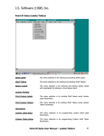
1. When configuring the Flexible Interface Module, first select 90B
to reset the configuration to factory defaults.
2. Configure screens 3, 21, and 11 (in this order) as shown on the
following pages:
Publication 2755-6.7
Flexible Interface Module Application
C–5
2760–RB
SERIES A REVISION J
COPYRIGHT 1989
ALLEN–BRADLEY COMPANY, INC.
––––––––––––––––––––––––––––––––––––––––––––––––––––
1X – CONFIGURATION PARAMETERS
2X – IDENTIFICATION NUMBERS
3 – DEVICE PORT PROTOCOL NAMES
4DM – MATCH CODE ENTRIES
5I – DISCRETE BYTE INPUT ENTRIES
6 – THE DATA MATRIX ENTRIES
7 – THE PASS THROUGH ENTRIES
8 – NON–VOLATILE SCRATCH PAD AREA
9XF – RB MODULE FUNCTIONS
AX – HARDWARE DIAGNOSTICS
BX – SOFTWARE DIAGNOSTICS
C – EXIT CONFIGURATION MODE
WHERE X (0 TO 7) AND D (1 TO 3) ARE PORT NUMBERS WHICH ARE DEFINED BELOW :
0 – RB CMMND PRCSS 2 – SERIAL PORT 2 4 – CONFIG PORT 6 – I/O RACK SLT 1
1 – SERIAL PORT 1 3 – SERIAL PORT 3 5 – I/O RACK SLT 0 7 – RESERVED
WHERE F (A TO E) ARE FUNCTIONS THAT RB CAN PERFORM WHICH ARE DEFINED BELOW :
A – RESET B – SET DEFAULTS C – FLUSH D – INITIALIZE E – CLEAR DIAGS
WHERE M (A TO T) AND I (A TO H) ARE ENTRY NUMBERS FOR THE SELECTION MADE ABOVE.
ENTER A MAIN MENU SELECTION:
ENTER A MAIN MENU SELECTION: 3
PORT 1 = COPYRIGHT 1989
ALLEN–BRADLEY COMPANY, INC.
2760–SFC1 DT , SERIES A , REVISION B (YES/NO) = YES.
PORT 2 = COPYRIGHT 1989
ALLEN–BRADLEY COMPANY, INC.
2760–SFC1 DT , SERIES A , REVISION B (YES/NO) = YES.
PORT 3 = COPYRIGHT 1989
ALLEN–BRADLEY COMPANY, INC.
2760–SFC1 DT , SERIES A , REVISION B (YES/NO) = YES.
EDIT THIS SELECTION (YES/NO) ?
Publication 2755-6.7
C–6
Flexible Interface Module Application
ENTER A MAIN MENU SELECTION: 21
DUMB TERM. UNSPECIFIED PROTOCOL, 13fh (YES/NO) = YES.
EDIT THIS SELECTION (YES/NO) ?
ENTER A MAIN MENU SELECTION: 11
MODEM CONTROL (ENABLE/DISABLE) = DISABLE.
9600 BITS PER SECOND (YES/NO) = YES.
8 BITS NO PARITY (YES/NO) = YES.
XON/XOFF (ENABLE/DISABLE) = DISABLE.
RS232 (YES/NO) = YES.
RECEIVE MATRIXING (ENABLE/DISABLE) = DISABLE.
BYTE SWAPPING (ENABLE/DISABLE) = ENABLE.
BINARY DATA NO CONVERSIONS (YES/NO) = YES.
HDR/TLR ON OUTPUT (ENABLE/DISABLE) = ENABLE.
HEADER BYTE LENGTH (DEC 0...4) = 0.
HEADER DATA[0] (HEX 0...ff) = 0.
HEADER DATA[1] (HEX 0...ff) = 0.
HEADER DATA[2] (HEX 0...ff) = 0.
HEADER DATA[3] (HEX 0...ff) = 0.
TRAILER BYTE LENGTH (DEC 0...4) = 2.
TRAILER DATA[0] (HEX 0...ff) = a.
TRAILER DATA[1] (HEX 0...ff) = d.
TRAILER DATA[2] (HEX 0...ff) = 0.
TRAILER DATA[3] (HEX 0...ff) = 0.
MAX DATA BYTE LENGTH (DEC 0...124) = 0.
MIN DATA BYTE LENGTH (DEC 0...124) = 0.
CONTINUE THIS SELECTION (YES/NO) ?
3. Make sure PLC program is written to access Flexible Interface
Module data.
Publication 2755-6.7
Appendix
D
SLC 5/03, 5/04 Controller
Application
This appendix describes how to configure and operate the scanner
when connected to an SLC 5/03, 5/04 controller.
!
ATTENTION: Do not install the RS-232 Synapse
cable with power applied to either the Synapse cable or
SLC controller. Failure to follow this caution may
result in damage to the scanner, Synapse cable, or SLC.
For additional reference you should refer to the following
publications:
• Advanced Programming Software (APS) User Manual
• Advanced Programming Software (APS) Reference Manual
Publication 2755-6.7
D–2
SLC 5/03, 5/04 Controller Application
Hardware Connections
The scanner connects to the Channel 0 port of the SLC with an
RS-232 Synapse cable (Catalog No. 2755-HFC-SR2-01).
Scanner
Scanner Cable
Power Supply
RS-232 Synapse Cable
(2755-HFC-SR3-01)
Note: The power supply
should be connected last.
SLC 5/04
To Channel 0 Port
Channel 0
Scanner Configuration
Configure the scanner using the bar codes described in Chapter 1.
The SLC controller does not require any specific scanner
configuration. However, you will need to configure the cable
communication parameters as described on the next page.
Publication 2755-6.7
SLC 5/03, 5/04 Controller Application
D–3
Configuration Codes for SLC Application
1. After making the necessary connections, scan this symbol to set
the scanner to its default settings.
Set Scanner Defaults
2. Set the bar code suffix to CR LF (ASCII equivalent 7013) by
scanning the following labels.
Suffix
7
1
0
3
Publication 2755-6.7
D–4
SLC 5/03, 5/04 Controller Application
3. Send the data then the suffix by scanning these labels.
Scan this Symbol First
Send <Data> <Suffix>
Scan Enter after Scanning Option
4. Set the RS-232 Synapse cable to defaults by scanning the
following:
Set RS-232 Synapse Cable Defaults
5. The cable defaults will work with the SLC 5/03, 5/04. Your
application may have specific requirements. Chapter 3 lists the
settings that can be modified. If you change a communication
setting, make sure the SLC controller is configured to accept the
change.
Publication 2755-6.7
SLC 5/03, 5/04 Controller Application
D–5
SLC 5/03, 5/04 Setup
You will need to configure the SLC, refer to the user manuals and
following instructions:
1. Set the SLC Channel 0 to User in the Channel 0 Configuration
screen
Publication 2755-6.7
D–6
SLC 5/03, 5/04 Controller Application
2. Configure Channel 0 in the Channel 0 User Mode Configuration
screen.
Note that Termination 1 is set for \a or Line Feed [LF], and
Termination 2 is set for \d or Carriage Return [CR]. These
terminators, along with the ARL instruction in the SLC, allow you to
read one message at a time with [CR] [LF] terminators.
Publication 2755-6.7
SLC 5/03, 5/04 Controller Application
D–7
SLC Program
The sample ladder logic listing below instructs the SLC 5/03 or 5/04
to:
Rung 2:0 – Read one string of ASCII data terminated with a
[CR] [LF].
Refer to the SLC 5/03 user manual for detailed information on using
the SLC 5/03 or 5/04 programming software.
Publication 2755-6.7
Appendix
E
PLC-5 Controller Application
This appendix describes how to configure and operate the scanner
when connected to a PLC-5 controller.
!
ATTENTION: Do not install the RS-232 Synapse
cable with power applied to either the Synapse cable or
PLC controller. Failure to follow this caution may
result in damage to the scanner, Synapse cable, or PLC.
For additional reference you should refer to the following
publications:
• PLC-5 User Manual
• 6200 Series Programming Software User Manual
Publication 2755-6.7
E–2
PLC-5 Controller Application
Hardware Connections
The scanner connects to the Channel 0 port of the PLC with an
RS-232 Synapse cable (Catalog No. 2755-HFC-SR2-01). The
connections are shown in the scanner user manual (Publication
2755-6.2).
Scanner
Power Supply
Scanner Cable
RS-232 Synapse Cable
(2755-HFC-SR2-01)
Note: The power supply
should be connected last.
PLC-5
To Channel 0 Port
Scanner Configuration
Configure the scanner using the bar codes described in Chapter 1.
The PLC controller does not require any specific scanner
configuration. However, you will need to configure the cable
communication parameters as described on the next page.
Publication 2755-6.7
PLC-5 Controller Application
E–3
Configuration Codes for PLC Application
1. After making the necessary connections, scan the following
following bar code symbol to set the scanner to its default
settings.
Set Scanner Defaults
2. Set the RS-232 Synapse cable to defaults by scanning this label.
Set RS-232 Synapse Cable Defaults
3. Set the bar code suffix to CR LF (ASCII equivalent 7013) by
scanning the following labels.
Suffix
7
1
0
3
Publication 2755-6.7
E–4
PLC-5 Controller Application
4. Send the data then the suffix by scanning these labels.
Scan this Symbol First
Send <Data> <Suffix>
Scan Enter after Scanning Option
5. The cable defaults will work with the PLC-5. Your application
may have specific requirements. Chapter 3 lists the settings that
can be modified. If you change a communication setting, make
sure the PLC controller is configured to accept the change.
Publication 2755-6.7
PLC-5 Controller Application
E–5
PLC-5 Setup
You will need to configure the Channel 0 port of the PLC-5. Refer
to the 6200 Series Programming Software user manual and the
following instructions.
1. Set the PLC-5 Channel 0 to User in the Channel 0 Configuration
screen.
Publication 2755-6.7
E–6
PLC-5 Controller Application
2. Configure Channel 0 in the User Mode Channel 0 Configuration
screen.
Note that Termination 1 is set for \0xa or Line Feed [LF], and
Termination 2 is set for \0xd or Carriage Return [CR]. These
terminators, along with the ARL instruction in the PLC-5, allow you
to read one message at a time with [CR] [LF] terminators.
Publication 2755-6.7
PLC-5 Controller Application
E–7
PLC Program
The sample ladder logic listing below instructs the PLC-5 to:
Rung 2:0 – Read one string of ASCII data terminated with a
[CR] [LF].
Refer to the PLC-5 user manual for detailed information on using the
PLC programming software.
Publication 2755-6.7
Appendix
F
DTAMt Plus DeviceNett
Application
This appendix describes how to configure and operate the scanner
when connected to a DTAM Plus Operator Interface on a DeviceNet
network.
Related Publications
Below is a list of related publications you may need to refer to when
using the DTAM Plus Operator Interface.
Publication No.
2707-800
2707-800.5
Title
DTAM Plus Operator Interface Module User Manual
DTAM Plus DeviceNet Operator Interface Document Update
2707-801
DTAM Programming Software Programming Manual
2707-802
Getting Started with DTAM Plus User Manual
Publication 2755-6.7
F–2
DTAMt Plus DeviceNett Application
Hardware Connections
The scanner connects to the DTAM Plus with the 9-Pin RS-232
Synapse cable (Catalog No. 2755-HFC-SR3-01). The cables and
connections are shown in Chapter 2 of the scanner user manual
(Publication 2755-6.2).
PLC-5 Controller
1771-SDN Module
DTAM Plus DeviceNet
RS-232
Synapse
Cable
Publication 2755-6.7
Scanner
DTAMt Plus DeviceNett Application
F–3
Codes for DTAM Plus Operator Interface DeviceNet Application
1. After making the necessary connections, scan the following
following bar code symbol to set the scanner to its default
settings.
Set Scanner Defaults
2. Set the bar code suffix to CR LF (ASCII equivalent 7013) by
scanning the following labels.
Suffix
7
1
0
3
Publication 2755-6.7
F–4
DTAMt Plus DeviceNett Application
3. Send the data then the suffix by scanning these labels.
Scan this Symbol First
Send <Data> <Suffix>
Scan Enter after Scanning Option
4. Set the RS-232 Synapse cable to defaults by scanning this label.
Set RS-232 Synapse Cable Defaults
5. The cable defaults will work with the DTAM Plus. Your
application may have specific requirements. Chapter 3 lists the
settings that can be modified. If you change a communication
setting, make sure the PLC controller is configured to accept the
change.
Publication 2755-6.7
DTAMt Plus DeviceNett Application
F–5
DTAM Plus Operator Interface Setup
You may need to configure the DTAM Plus Operator Interface
RS-232 port to accept the scanner data. Refer to the DTAM
Programming Software Programming Manual. Configure the
DTAM Plus Operator Interface serial port as shown below.
1. Open Screen Builder.
2. Open Create Screen.
3. Open Data Entry Screen.
4. Select Set Up Screen.
5. Select Data Entry.
6. Select ASCII Input.
7. Set up DTAM.
Publication 2755-6.7
F–6
DTAMt Plus DeviceNett Application
DeviceNet Operation
The DTAM Plus DeviceNet operates as a Group 2 Server on the
DeviceNet network. It supports the Unconnected Message Manager
(UCMM). The DTAM Plus DeviceNet implements the predefined
master/slave connection set, operating as a slave device. It does not
initiate communications except for a Duplicate Node Address check
on power-up.
The DTAM Plus DeviceNet supports the polled I/O method of
exchanging data with a master, in the following sequence:
1. The designated master writes an output image to the DTAM Plus
DeviceNet using the Poll Command message.
2. The DTAM Plus DeviceNet responds to the poll command by
returning an input image back to the master in a Poll Response
message.
Note: The size of the input and output images (also referred to as
files) are individually configurable from 0 words to 121 words
each, to optimize DeviceNet network loading.
3. The DTAM Plus DeviceNet application program interacts with
data contained in the input and output files.
4. Data Display screens are used to view input and output data.
5. Data Entry screens are used to modify input and output data from
the scanner.
Publication 2755-6.7
Appendix
G
ASCII Chart
ASCII
Value
Full ASCII
Code 39
Encode
Char.
Character
(Control Code)
ASCII
Value
Full ASCII
Code 39
Encode
Char.
Character
(Control Code)
1000
%U
NULL (CTRL 2)
1016
$P
DLE (CTRL P)
1001
$A
SOH (CTRL A)
1017
$Q
DC1 (CTRL Q)
1002
$B
STX (CTRL B)
1018
$R
DC2 (CTRL R)
1003
$C
ETX (CTRL C)
1019
$S
DC3 (CTRL S)
1004
$D
EOT (CTRL D)
1020
$T
DC4 (CTRL T)
1005
$E
ENQ (CTRL E)
1021
$U
NAK (CTRL U)
1006
$F
ACK (CTRL F)
1022
$V
SYN (CTRL V)
1007
$G
BEL (CTRL G)
1023
$W
ETB (CTRL W)
1008
$H
BS (CTRL H)
1024
$X
CAN (CTRL X)
1009
$I
HT (CTRL I)
1025
$Y
EM (CTRL Y)
1010
$J
LF (CTRL J)
1026
$Z
SUB (CTRL Z)
1011
$K
VT (CTRL K)
1027
%A
ESC (CTRL[)
1012
$L
FF (CTRL L)
1028
%B
FS (CTRL \)
1013
$M
CR (CTRL M)
1029
%C
GS (CTRL ])
1014
$N
SO (CTRL N)
1030
%D
RS (CTRL 6)
1015
$O
SI (CTRL O)
1031
%E
US (CTRL _ )
Publication 2755-6.7
G–2
ASCII Chart
ASCII
Value
Full ASCII
Code 39
Encode
Char.
Character
ASCII
Value
Full ASCII
Code 39
Encode
Char.
Character
1032
SP
SP
1057
9
9
1033
/A
!
1058
/Z
:
1034
/B
’
1059
%F
;
1035
/C
#
1060
%G
<
1036
/D
$
1061
%H
=
1037
/E
%
1062
%I
>
1038
/F
&
1063
%J
?
1039
/G
’
1064
%V
@
1040
/H
(
1065
A
A
1041
/I
)
1066
B
A
1042
/J
*
1067
C
C
1043
/K
+
1068
D
D
1044
/L
,
1069
E
E
1045
-
-
1070
F
F
1046
.
.
1071
G
G
1047
/
/
1072
H
H
1048
0
0
1073
I
I
1049
1
1
1074
J
J
1050
2
2
1075
K
K
1051
3
3
1076
L
L
1052
4
4
1077
M
M
1053
5
5
1078
N
N
1054
6
6
1079
O
O
1055
7
7
1080
P
P
1056
8
8
1081
Q
Q
Publication 2755-6.7
ASCII Chart
ASCII
Value
Full ASCII
Code 39
Encode
Char.
1082
G–3
Character
ASCII
Value
Full ASCII
Code 39
Encode
Char.
Character
R
R
1105
+I
i
1083
S
S
1106
+J
j
1084
T
T
1107
+K
k
1085
U
U
1108
+L
l
1086
V
V
1109
+M
m
1087
W
W
1110
+N
n
1088
X
X
1111
+O
o
1089
Y
Y
1112
+P
p
1090
Z
Z
1113
+Q
q
1091
%K
[
1114
+R
r
1092
%L
\
1115
+S
s
1093
%M
]
1116
+T
t
1094
%N
^
1117
+U
u
1095
%O
_
1118
+V
v
1096
%W
’
1119
+W
w
1097
+A
a
1120
+X
x
1098
+B
b
1121
+Y
y
1099
+C
c
1122
+Z
z
1100
+D
d
1123
%P
{
1101
+E
e
1124
%Q
|
1102
+F
f
1125
%R
}
1103
+G
g
1126
%S
~
1104
+H
h
1127
Undefined
Publication 2755-6.7
G–4
ASCII Chart
ALT Key Values
ALT Key
Value
Keystroke
ALT Key
Value
Keystroke
ALT Key
Value
Keystroke
2064
ALT 2
2075
ALT K
2086
ALT V
2065
ALT A
2076
ALT L
2087
ALT W
2066
ALT B
2077
ALT M
2088
ALT X
2067
ALT C
2078
ALT N
2089
ALT Y
2068
ALT D
2079
ALT O
2090
ALT Z
2069
ALT E
2080
ALT P
2091
ALT [
2070
ALT F
2081
ALT Q
2092
ALT \
2071
ALT G
2082
ALT R
2093
ALT ]
2072
ALT H
2083
ALT S
2094
ALT 6
2073
ALT I
2084
ALT T
2095
ALT -
2074
ALT J
2085
ALT U
Keystroke
Miscellaneous Key Values
Misc. Key
Value
Keystroke
Misc. Key
Value
Keystroke
Misc. Key
Value
3001
PA 1
3009
CMD 7
3017
_
3002
PA 2
3010
CMD 8
3018
1/
2
3003
CMD 1
3011
CMD 9
3019
W
3004
CMD 2
3012
CMD 10
3020
w
3005
CMD 3
3013
O
3021
|
3006
CMD 4
3014
o
3022
0/00
3007
CMD 5
3015
h
3008
CMD 6
3016
–
Publication 2755-6.7
ASCII Chart
G–5
Numeric Key Values
Numeric
Key Value
Keystroke
Numeric
Key Value
Keystroke
Numeric
Key Value
Keystroke
6042
*
6049
1
6056
8
6043
+
6050
2
6057
9
6044
Undefined
6051
3
6058
Enter
6045
–
6052
4
6059
Num Lock
6046
.
6053
5
6060
00
6047
/
6054
6
6048
0
6055
7
Extended Keyapd Key Values
Numeric
Key Value
Keystroke
Numeric
Key Value
Keystroke
Numeric
Key Value
Keystroke
7001
Break
7008
Backspace
7015
Up Arrow
7002
Delete
7009
Tab
7016
Down Arrow
7003
Page Up
7010
Print Screen
7017
Left Arrow
7004
End
7011
Insert
7018
Right Arrow
7005
Page Down
7012
Home
7019
Back Tab
7006
Pause
7013
Enter
7007
Scroll Lock
7014
Escape
Publication 2755-6.7
TEST SYMBOLS
1 2 3 4 5
Code 128
A
1
2 3 4
Code 39
1 2 3 4 5
Code 93
B
PDF-417
1 2 3 4 5
Discrete 2 of 5
1 2 3 4 5
EAN 128
1 234567 891019
EAN 13
A 1 2 3 4 B
Codabar
012345
Interleaved 2 of 5
1234 5670
EAN 8
0
123456
UPC E
5
1
23456 78901
UPC A
2
Synapset is a trademark of Symbol Technologies Inc.
AdaptaScant is a trademark of Allen-Bradley
Worldwide representation.
Argentina • Australia • Austria • Bahrain • Belgium • Brazil • Bulgaria • Canada • Chile • China, PRC •
Colombia • Costa Rica • Croatia • Cyprus • Czech Republic • Denmark • Ecuador • Egypt • El Salvador •
Finland • France • Germany • Greece • Guatemala • Honduras • Hong Kong • Hungary • Iceland • India •
Indonesia • Ireland • Israel • Italy • Jamaica • Japan • Jordan • Korea • Kuwait • Lebanon • Malaysia •
Mexico • Netherlands • New Zealand • Norway • Pakistan • Peru • Philippines • Poland • Portugal •
Puerto Rico • Qatar • Romania • Russia–CIS • Saudi Arabia • Singapore • Slovakia • Slovenia • South
Africa, Republic • Spain • Sweden • Switzerland • Taiwan • Thailand • Turkey • United Arab Emirates •
United Kingdom • United States • Uruguay • Venezuela • Yugoslavia
Allen-Bradley Headquarters, 1201 South Second Street, Milwaukee, WI 53204 USA, Tel: (1)
414 382-2000 Fax: (1) 414 382-4444
Publication 2755-6.7 – September 1996
40062-358-01(A)
Copyright 1996 Allen-Bradley Company, Inc. Printed in USA
October 1995
1784-6.5.19-RN1