1
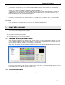
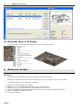
New Features in ARCHLine.XP 2007
News
Information in this document is subject to change without notice and does not represent a commitment on the part of
CadLine. The software, which includes the information contained in any databases, described in this document is
furnished under a license agreement or nondisclosure agreement. The software may be used or copied only in
accordance with the terms of the agreement. It is against the law to copy the software on any medium except as
specifically allowed in the license or nondisclosure agreement. The licensee (purchaser) may make one copy of the
software for the purpose of creating a -backup copy. No part of this manual may be reproduced, transmitted, transcribed,
or translated into any language in any form or by any means, without the express written permission of CadLine.
First Edition
2007. CadLine. All rights reserved.
In no event shall CadLine be liable for special, indirect or consequential damages in connection with or arising from the
use of this document or any programs contained herein.
Microsoft, MS, and MS-DOS are registered trademarks and Windows is a trademark of Microsoft Corporation.
®
ARCHLine.XP is a trademark of CadLine.
This manual was produced using Microsoft Word and ARCHLine.XP
CadLine
®.
Contents
I
Contents
®
1.
CadLine releases ARCHline.XP 2007....................................................... 3
2.
Advanced AutoCAD compatibility ............................................................. 4
2.1.
2.2.
2.3.
3.
Color table manager.................................................................................... 5
3.1.
3.2.
3.3.
3.4.
4.
Load external reference ...................................................................... 7
External reference manager................................................................ 7
Shortcut menu..................................................................................... 8
Raster images.............................................................................................. 8
5.1.
5.2.
5.3.
5.4.
6.
Standard handling of color tables........................................................ 5
AutoCad color table ............................................................................ 5
New color tables ................................................................................. 6
Query the color of an element............................................................. 6
External references..................................................................................... 6
4.1.
4.2.
4.3.
5.
AutoCAD compatible coordinate input ................................................ 4
Using of command aliases .................................................................. 4
DXF/DWG import/export ..................................................................... 4
Overview ............................................................................................. 8
Insert raster image .............................................................................. 9
Image manager................................................................................... 9
Show/Hide Raster in 3D window....................................................... 10
Advanced interface ................................................................................... 10
6.1.
6.2.
6.3.
6.4.
6.5.
6.6.
6.7.
6.8.
Faster handling of drawings .............................................................. 11
Flexible use of sets ........................................................................... 11
Advanced 3D build options ............................................................... 11
Rearranged main menu .................................................................... 11
Customizable side menu (toolbox) .................................................... 12
Modular structure .............................................................................. 13
New toolbars ..................................................................................... 14
Changed toolbars.............................................................................. 14
7.
Construction grid ...................................................................................... 15
8.
Dynamic section in 3D .............................................................................. 15
9.
Construction animation module .............................................................. 16
10.
Window opening direction in 3D.............................................................. 17
11.
Renewed curtain wall................................................................................ 18
12.
Terrain and Volume sketch design.......................................................... 20
12.1. Terrain............................................................................................... 20
12.2. Volume sketch .................................................................................. 21
®
ARCHLine.XP 2007
.
®
ARCHline.XP 2007 News
3
1. CadLine releases ARCHline.XP® 2007
The CadLine proudly announces the release of the latest version of its own developed Computer Aided Architectural
®
Design (CAAD) software, ARCHLine.XP 2007.
Advanced AutoCAD compatibility
®
The ARCHLine.XP 2007 imports and exports the DWG data format — used commonly by architects, engineers,
designers, and virtually all CAD-related software applications.
®
ARCHLine.XP 2007 uses the latest DWGdirect 2.2 libraries, based on the industry standard OpenDWG, which is widely
®
supported by commercial software vendors, and the engineering community. ARCHLine.XP 2007 utilizes the new ODA
®
libraries to interpret the updated DWG 2007 file format. ARCHLine.XP 2007 will read, display, and write DWG 2007 files.
Although the focus of ARCHLine.XP® 2007 development was on the DWG 2007 compatibility, other major enhancements
can be found in this release:
New Modular Product Structure
ARCHLine.XP® 2007 has been designed to enable the creation of a wide range of architectural design solutions for all
types of market and application. The modular structure gives customers the ability to easily introduce additional
functionality into their applications when required.
New entry level product — ARCHline.XP 2007 DRAFT.
This version supports only the two dimensional design. The version is designed for having additional licenses in the
Architectural Studios.
New color table
New color table manager provides the ability to effectively organize, import color tables including real AutoCAD color
indexes.
New XREF feature
Xref is an instance within a drawing referring to another document in DWG, DXF, or ASC format.
New enhanced Terrain and Volume Sketch design
Construction grid
New editable intelligent grid with linked architectural elements.
Dynamic 3D Section Plane
3D section cut effect with interactive section plane movement.
Building animation
Virtual construction - animation of construction schedules provides useful information to clients and professionals.
Raster image
Enhancements for raster image handling: raster image manager.
New user Interface
Multiple enhancements for user interface include:
Improved display performance when using dynamic zoom and pan for large drawings by managing OPENGL window.
Shortcuts buttons for fast switch – GRID, SNAP, OSNAP, ORTHO, POLAR commands.
New compatible commands to define coordinates to specify absolute, relative and polar coordinates.
New top menu and toolbox interface structure.
Enhanced Set manager for all elements – Set drop-down menu lists the element related sets loaded in the project
Repeat Last Command can be used to repeat the most recently issued command pressing ENTER or using the Default
right click menu.
Command Alias Table
An alias lets you create a shortcut name for a command. By using aliases, you save a lot of time when doing tasks you do
frequently.
Enhanced Layer drop-down menu
Fast Layer editing directly in the drop-down list.
®
ARCHLine.XP 2007
®
4
ARCHline.XP 2007 News
In addition to the new features, dozens of repairs and minor improvements were added as well, including:
Setup supports Microsoft Windows Vista
Rendering supports advanced visual features including high performing photorealistic rendering with super-sampling antialiasing, and colored shadows from semi-transparent materials like stained glass.
Improved PDF export provides more flexible output options e.g. transparent raster images.
Performance improvements with drawings containing big raster images
OpenGL approximation lines are hidden by default.
Improved multilayer wall connection, connection of parallel walls with different wall width.
Door, window macros – Opening directions visualized in 3D view.
2. Advanced AutoCAD compatibility
Introduction
Thanks to the advanced compatibility you can meet numerous functions and interface elements which help your work if
you worked with other CAD applications so far.
These are the following:
2.1. AutoCAD compatible coordinate input
With the help of AutoCAD compatible coordinate input possibility you have to learn nothing new. If you want to work with
®
coordinate inputs. You just have to use your existing knowledge. ARCHLine.XP 2007 complies with this common working
method.
The comma as separator:
®
Opposed to the conventions in ARCHLine.XP 2007 you can use the comma as separator for coordinate inputs. For this
you have to switch off the Comma (,) in Decimal point allowed option in the File menu – Preferences – General – Other
dialog.
Absolute coordinate input:
Relative coordinate input :
Absolute polar coordinate input:
Relative polar coordinate input:
X,Y ENTER
@X,Y ENTER
numR<numFi
@numDr<numFi
2.2. Using of command aliases
Among the users of command-line based applications the use of text commands is very common. The program enables
the use of these commands as well.
If you work with text commands, you will like the so called command alias. With the help of this you can work without
releasing your mouse because you can easily type these aliases. Additionally, you can define your own command aliases.
AutoCAD users can define so called command aliases. A command alias is a shortening of a text command. Do not mix it
up with the shortcut keys.
Without using aliases you have to type the entire word ‘erase’ in the command line, for example, to start the delete
command. In case of a properly defined command alias it is enough to type the letter ‘e’ and then pressing ENTER.
Definition of command aliases
®
You can overview and edit command aliases used in ARCHLine.XP 2007 in the File menu – Preferences – Customize –
Command alias.
2.3. DXF/DWG import/export
DXF/DWG file format allows you to exchange your drawings with other CAD users. You can export or import even DWF
(Design Web Format) files as well. You can quickly select the file format you wish to save your work in.
CadLine
®
.
ARCHline.XP 2007 News
5
Import
The program is capable to process the latest DXF, DWG and DWF file formats and to load these files into your own
project either as part of your project or as external references.
A higher level of color table handling is available in the imported drawings, too.
The program is able to recognize the original AutoCAD colors of the elements in the imported drawings, which can be
modified later in the specific color table. When you export a drawing like this, there is no need to convert the colors
because the drawing uses the same AutoCAD color table.
Export
If you wish to send your work to your colleagues who use other CAD systems, for example, this is the simplest method
you can use.
File version
You can choose from the released AutoCAD versions. The exported file will be compatible with the selected AutoCAD
version. This way the exported file can be used by users with previous AutoCAD versions.
3. Color table manager
There is a new color management in the program.
Standard handling of color tables.
It is possible to load AutoCad color tables.
It is possible to add new color tables.
It is possible to query a specified color afterwards.
3.1. Standard handling of color tables
®
Color is among the properties of each ARCHLine.XP element. Elements are represented with their colors on the screen
or on the printed documents. Besides the color properties of elements, colors have important role at materials when you
represent materials with colors. In both cases the program uses RGB colors.
®
Colors can be chosen from different color tables. The handling of these colors became standard in ARCHLine.XP 2007.
New material with color
If you create a new material by a Ral, Sikkens or Panton color, the name of the color will automatically specify the name of
the material, too. You can modify this material name, of course.
3.2. AutoCad color table
In the color dialog you can find the AutoCad color table among the others.
®
ARCHLine.XP 2007
®
6
ARCHline.XP 2007 News
If you import a drawing created in AutoCAD, the drawing elements will keep their AutoCad color table settings. Here you
can modify the color of an element.
If all the drawing elements have colors from AutoCad color table, you don’t need to convert colors at file export. The
exported drawing will appear with the same colors in AutoCad.
3.3. New color tables
Different CAD applications can use numerous color tables. Some of these color tables are downloadable from the web.
®
In ARCHLine.XP 2007 it is possible to load color tables that follow the format of Adobe or AutoCad ColorBook.
These files can have .acb extension in binary (Adobe) or XML (AutoCad) file format.
3.4. Query the color of an element
Any color you have specified can be queried later on.
After you have specified a color to an element, open the properties dialog of the element and click the color button.
The Color table dialog appears with the appropriate color table, showing the previously specified color selected in that
color table.
Under Components you can read the RGB codes and the Hue, Luminosity, and Saturation values.
4. External references
You can perform several operations on referenced drawing files including attaching, updating and detaching them. When
you attach a drawing as external reference (referred later as xref), you link that referenced drawing to the current drawing;
any changes to the referenced drawing are displayed in the current drawing when it is opened or reloaded. Attached xrefs
can be nested: that is, you can attach an xref that contains another xref. When you open a drawing, all xrefs update
automatically. You can also update xrefs whenever you want to ensure that the most current versions are displayed in
your drawing. When you archive final drawings that contain xrefs, you can choose how you store the xrefs in the drawings.
The xref drawing can be DXF, DWG or ASC drawing.
CadLine
®
.
ARCHline.XP 2007 News
7
4.1. Load external reference
Using the Tools menu –External Reference command you can load a DXF, DWG or ASC file like an external reference
The Open file dialog appears:
4.2. External reference manager
External references can be managed in the External reference manager dialog; you can attach, list, bind, detach, reload,
unload external references (xrefs) or modify their path in the current (or host) drawing.
Click the Tools menu – Xef Manager command. The External reference manager dialog appears.
In the dialog you can see all xrefs in the drawing in a
tree view or a
list view:
Tree view
This view represents the external references, displaying the relations between them. The tree view lists the level of nesting
relations of the attached external references. In tree view you can easily overview the nesting of each xref.
List view
It displays the flat listing of the attached external references and their attributes.
In list view you can see the reference name, status, size, date of modification, and path information of each xref.
®
ARCHLine.XP 2007
®
8
ARCHline.XP 2007 News
4.3. Shortcut menu
Right click on any element of the xref drawing appears the shortcut menu.
The header of the shortcut menu shows the path of the xref drawing.
5. Raster images
5.1. Overview
In the design work you may need raster images. You can create a raster image by using a general plan, a hand made
plan, a contour map, etc.
Raster images are either supplied in a digitalized form or available after scanning. Raster images can be imported into the
drawing to create a background.
Raster image
The raster image created this way contains background points (pixels). The number
of pixels defines the display resolution of the raster image and so its quality,
however it represents no other specific value. Accordingly, the raster image cannot
be considered particularly useful with respect to the actual drawing.
The image imported into the background unquestionably increases the aesthetic
value of the drawing but is only relevant if its scale aligns with the corresponding
scale of the drawing area. Thus the scale of the raster image has to be changeable.
You can load and use the raster images. Raster images behave like any other
drawing elements, so you can rotate, move, copy, scale, delete them as well. You
can apply the undo/redo commands for raster images, too. The image file formats
®
supported by ARCHLine.XP 2007 include the most common formats like BMP,
JPG, TIF. Images can be 1-bit black and white, 4-bit, 16 bit, or 24-bit color ones.
®
ARCHLine.XP 2007 supports the transparent pixels. Transparency is scalable
between 0-255.
These raster images can be used for the following:
CadLine
.
®
ARCHline.XP 2007 News
9
photogrammetry,
calibration (e.g. in case of floor plans or urban development plans).
The images created on the model with the photorealistic image editor can be saved as image files, and later can
be set as raster images on the drawing or on the plan.
The raster image becomes part of the drawing, and you save it with the plan. You can apply a number of edit commands
to the loaded raster images. These commands only concern the active raster image; the operation does not affect the
image file itself.
Use the Image editor if you wish to carry out operations on the image file.
The raster images can be managed easily in the Image manager dialog: you can attach, detach, reload, hide an image or
show only its frame on the current drawing.
How to use it?
You can find the raster image commands in the Drafting menu or in the Shortcut menu by clicking with right mouse button
on a raster image:
Drafting menu:
5.2. Insert raster image
To insert and place a raster image, you can use the Drafting menu – Raster image command.
Insert only as reference
Image can be referenced and placed in a drawing file. When this option is active, the raster image is not actually part of
the drawing file and it is not attached to the current project. The image is linked to the drawing file through a path name.
Linked image paths can be changed at any time.
5.3. Image manager
Raster images can be managed easily in the Image manager dialog: you can attach, detach, reload, hide an image or
show only its frame on the current drawing.
Click the Drafting menu – Image Manager command. The Image manager dialog appears with a table.
®
ARCHLine.XP 2007
®
10
ARCHline.XP 2007 News
5.4. Show/Hide Raster in 3D window
You can display the raster image in 3D window placed on the current floor elevation.
6. Advanced interface
Introduction
®
The advanced interface of ARCHLine.XP 2007 helps you to work more effectively.
During the development of the new interface the enhancing of speed and effectiveness were the first priorities.
The following elements are included in the new interface:
Hardware-accelerated drawing representation.
Dynamic zoom. You can set the appropriate view precisely with your mouse.
Flexible use of sets. Get familiar with this working method to be more effective.
Advanced 3D build of the model. Thanks to the new options you can generate the 3D model even simpler.
More clear and logical rearranged text menus.
Customizable side menu.
CadLine
.
®
ARCHline.XP 2007 News
11
6.1. Faster handling of drawings
®
Thanks for adopting the sophisticated drawing handling technology used in ARCHLine.XP 2007 you can work faster and
smoother – from now not just in the 3D model representation but in the 2D windows, too.
Now you can use the OpenGL technology, which also helps the fast representation of 3D models, in your entire project.
OpenGL mode in all windows
To use the OpenGL technology project-wide, apply the Create all (2D/3D) windows in OpenGL mode option in the File
menu – Preferences – General – OpenGL settings dialog.
Thanks to the OpenGL technology, the time-consuming commands like dynamic zoom and pan became much faster in
large drawings, too. Also, you don’t have to wait for the regeneration of 2D window contents.
6.2. Flexible use of sets
During your work you often need to change the properties of different architectural or 2D elements. To create a floor plan,
®
for example, you need different wall properties for headwalls, partition-walls or foundations. ARCHLine.XP 2007 enables
to store these settings in sets.
Previously you had to open the properties dialog of an element to change its set. Now you do not need to do this. You can
select the appropriate sets by one click from a roll-down list.
Selecting a set to create new element
According to the element type you work with, the appearing list of sets changes dynamically.
Applying set to an existing element
You can also change the properties of an existing element with the flexible use of sets.
Select the element. In the status bar a list of sets appears according to the element type. If the selected element already
6.3. Advanced 3D build options
There are new 3D build options in the Build 3D model dialog to help an easier and clearer 3D model generation.
Floor selection
For more complex buildings with a number of floors it is not enough to use the Active floor or All floors options to create
the proper details of the 3D model. Beside the old Active floor and All floors options you also have the option to Select
floors to build up the 3D model of your drawing. This enables more varieties in the 3D model representation.
6.4. Rearranged main menu
Reading the main menus from left to right, first you find the menu for the file management, then comes the menus
necessary for editorial works. In the middle you find the menus including the drawing commands, and finally come the
menu group for finishing your work.
®
ARCHLine.XP 2007
®
12
ARCHline.XP 2007 News
Modeling menu
It’s a new menu. This menu groups the commands you need to create or modify architectural 3D elements and define their
properties.
Drafting menu
It’s a new menu. This menu groups the commands you need to create or modify 2D elements and define their properties.
Tools menu
New menu items are added to this menu.
External reference – With this command you can link external drawing files to your actual drawing.
Xref manager – This command starts the Reference manager dialog to overview and to manage your external references.
Add-on menu
It’s a new menu. This menu includes modules that can be accessed as add-ons.
Help menu
There is no change in the menu structure but he content of the About dialog has changed. In this dialog you can find all
relevant information about your software installation. On the top of the dialog you can read the name of the program and
the license owner’s name.
6.5. Customizable side menu (toolbox)
This chapter includes basic information about the use of the new side menu (referred also as toolbox).
Side menu (toolbox) settings
•
To customize your toolbox settings:
Open the File menu – Preferences – General – Toolbox setting dialog,
or
click with your right mouse button on the
header of a side menu group.
The following dialog appears:
Use of the side menu
From functional point of view you can use the side menu in two styles: either with the new or the classic layout. You can
switch between these layouts.
In any case you can enjoy additional advantages of the side menu:
®
You can detach it from or dock to the interface of ARCHLine.XP 2007 as you like.
You can resize it as you like. You can make the side menu wider of narrower according to your decision, thus you can
®
define the room it takes up from the interface of ARCHLine.XP 2007.
You can use the settings described in the previous chapter in both cases.
Next you will get a short overview about the differences of the two layout styles from working point of view.
CadLine
®
.
ARCHline.XP 2007 News
13
New side menu layout
Changing the element properties: In the new side menu layout you can either use the right mouse button in the
conventional way or the left mouse button in a separate properties submenu to access the properties dialog of a drawing
element.
Use of commands: The most common commands can be found inside the main menu groups. More commands are
available in the submenus. Submenus distinguished by small black arrows. Depending on the toolbox settings the position
of the black arrow is different; in case of Icons only setting the black arrow appears in the top-right corner of the icon,
otherwise it appears beside the name of the submenu.
You must always use your left mouse button to select a command or go into a submenu.
Classic layout
Changing the element properties: In classic layout you can set the properties of an element similarly to the previous
®
versions of ARCHLine.XP 2007. Click with your right mouse button on the symbol of the element in the menu group. In
this side menu layout this is the only way to access the properties dialog.
®
Use of commands: Similarly to the previous versions of ARCHLine.XP 2007, the element-specific commands appear in
a toolbar when you select an element. You can select the necessary commands on this toolbar.
6.6. Modular structure
®
The modular structure of ARCHLine.XP 2007 enables to configure the software according to the marked demands.
Thanks to the modular structure it is possible to extend the software capabilities arbitrary with new modules.
Registering a module
To use a purchased module, first you have to register it with the code. The registration dialog of a module can be
accessed through the Registration menu that can be found among the command menus items of the module.
In the appearing dialog you can read the module name and enter the module registration code.
®
ARCHLine.XP 2007
®
14
ARCHline.XP 2007 News
6.7. New toolbars
®
To ensure direct access to frequently used commands, new toolbars are available in ARCHLine.XP 2007.
Info toolbar
Info commands which were available from the side menu so far have been moved to the Info toolbar.
The commands found in the toolbar are the same as in the old side menu.
(You can read the detailed description of the commands in the user’s manual.)
2D edit toolbar
This toolbar collects the frequently used 2D edit commands which were available only from the menus in the previous
versions. Also, there are some new commands.
(You can read the detailed description of the commands in the user’s manual.)
6.8. Changed toolbars
®
The expansion of some toolbars in ARCHLine.XP 2007 makes your work more effective. The new toolbar elements were
either unavailable or circuitous to access so far.
Status bar
There are more new elements in the status bar. New element is the roll-down list of sets. You can read more details about
this in chapter Flexible use of sets. The picture below shows the new elements at the end of the status bar.
These are two-state switch buttons (x = ON, check-mark = OFF).
CadLine
®
.
ARCHline.XP 2007 News
15
7. Construction grid
Introduction
®
The Construction Grid module of ARCHLine.XP gives the possibility of creating the frame of the building with its structural
and other relevant architectural elements in a fast way. With the use of Construction Grid your task is not the drawing of
architectural elements but setting up appropriate rules. With the application of these rules you don’t have to draw columns,
beams, supporting walls and plinths, the program does it instead of you. ARCHline.XP creates the whole frame of the
building according to the rules you set up.
You have the following tools to do this:
You can define a construction grid. The location of the grid and the spacing of grid nodes are customizable.
In this grid you can specify regions where the structural elements must be created. In addition to this you can define
different bearing directions in a zone.
You can define positive and negative exceptions so structural elements can be created out of the grid nodes as well.
Before starting to work with Construction Grid, please read carefully this chapter. The main definitions and their
explanations are collected for your better understanding.
Grid
The grid is not just an aid for the better visual overview of the raster of the building frame; it also helps you to build up the
frame of the building. The lines of the grid are the main directions for the program, which define the rule of building up the
vertical and horizontal supporting elements. The main directions of the grid specify the possible positions of the reference
line of beams, while the intersection points of main directions specify the grid nodes, thus the possible positions of the
reference point of columns and plinths.
Grid nodes
Each intersection point in a Construction Grid is taken into consideration as a grid node. The grid nodes help in generating
structural elements. Grid nodes specify the position of plinths and columns, the connection points of the reference line of
beams to columns.
External contour
External contour defines an area in which the rules set up in the Construction Grid are applicable. You don’t have to create
exactly the same grid size as the building area, it is enough to separate the necessary areas by the external contours.
Range
Range is an area in which the structural elements logically belong to each other. There can be more ranges inside an
external contour.
Exceptions
Exceptions are special points where we either don’t want to apply the rules to some existing grid nodes or we want to
apply the rules to points outside of the grid nodes.
8. Dynamic section in 3D
This function enables you to define and create dynamic section in 3D. For this you have to work in an OpenGL 3D
window. You can use this function both in axonometric and perspective views.
The advantage of this function is that you can create a dynamic section defined by a section plane in real time. It is not just
a working tool for the architects but a spectacular representation of the building.
®
ARCHLine.XP 2007
®
16
ARCHline.XP 2007 News
Be aware of the following rules when you work with dynamic 3D section:
Size of the generated section: the size of the generated section is independent from the section plane you work with.
You will see the whole section in every case.
The angle of section: in every case a vertical architectural section will be created, independently from the tilt angle of the
section plane.
Section line created on the floor plan: along with the section a section line will be created on the floor plan. The length
of this section line is equal with the width of the dynamic section plane. The position of the section line is defined as the
horizontal centerline of the section plane projected on the floor plan.
9. Construction animation module
Introduction
®
The construction animation module of ARCHLine.XP 2007 makes enable to simulate the build up of a building. This way
you can play an animation like a “virtual construction” to your client.
For this you have the following tools:
After specifying the expected start date and end date of construction a build-up duration time needed for building up an
element can be assigned automatically to each construction element type. Additionally, you can specify the order of buildup of element types. You can specify the construction scheduling rules. (E.g. the time needed for build up the walls, the
work phase followed by walling etc.)
This construction schedule can be modified later by handling the elements in groups.
The advantage of handling groups is the ability of quick build-up date assignment to all architectural elements, even if you
have a large model.
Construction dates assigned to the elements can be modified individually. It can happen that certain elements are
constructed apart from their element type in a different time.
The animation can be played at any time before the final date assignment so you can check whether the assignments are
good.
The animation created this way can be saved in .avi file format so you can give it to your client.
Preparation
The program plays the animation in an OpenGL window; therefore you need an existing model in an OpenGL 3D window.
This window must be active.
The Construction animation is available in the Add-On menu – Animation submenu.
CadLine
.
®
ARCHline.XP 2007 News
17
Workflow
To create a Construction animation the following workflow is recommended:
Define the rule of date assignments.
Specify the start date and the expected end date of construction.
Generate a construction schedule by element groups:
Assign dates to element types with the help of Build date wizard.
Play the animation and check if construction order and duration of element types are correct.
If it is not correct, go back to the Build date wizard where you can still modify the values by element groups.
Assign the dates to the project.
Do a fine tuning:
After finishing with the date assignment by element types you can modify the dates assigned to the elements as cost
parameters individually. Play the animation to check the assignments.
Create the AVI video.
10. Window opening direction in 3D
In the doors/windows properties dialog you have the possibility to specify the possible opening directions. In
®
ARCHline.XP 2007 you have the option to represent these opening directions in the 3D model of doors/windows by
drawing opening direction symbols on doors/windows. This can be very useful in case of more detailed façade drawings.
There are two prerequisites to represent the opening direction symbols in 3D:
The represented door/window should be closed. You can set this in the door/window properties dialog.
The Draw opening direction option checkbox must be checked in the Build 3D model dialog.
®
ARCHLine.XP 2007
®
18
ARCHline.XP 2007 News
11. Renewed curtain wall
®
Similarly to other ARCHLine.XP 2007 elements, you can set the properties of curtain walls. You can store these
properties in sets. Curtain walls are created with their actual properties.
First specify the properties of curtain wall.
For this use the Modeling menu –Properties –Curtain wall command.
In case of full size curtain wall select the Full curtain wall command from the shortcut menu of wall.
or
In case of curtain with custom size wall select the Modeling menu - Window –Edit corner window command.
The curtain wall has the following properties:
The curtain wall can extend as far as the wall ends.
Divisions can be created in X an Y directions by specifying either the number of divisions or the glass plane dimensions in
horizontal and vertical directions. It is possible to define unequal divisions, too.
At the sides of the window it is possible to switch off the frames so you can see only the glass plane edges.
Curtain wall properties
The Modeling menu –Properties –Curtain wall command opens the Glass structure settings dialog.
Here you can find in the same dialog the glass structure definition and the properties of placing:
CadLine
.
®
ARCHline.XP 2007 News
19
®
ARCHLine.XP 2007
®
20
ARCHline.XP 2007 News
12. Terrain and Volume sketch design
12.1.
Terrain
®
The Terrain function of ARCHLine.XP 2007 – keeping the old good features – developed a lot. There are new functions
and setting possibilities.
For this you can use the following tools:
There are different options to set the appearance of a terrain. Optionally you can display the elevation values and the
numbering of terrain points.
All the necessary settings are available in the terrain properties dialog.
You can create Zones which helps you in conceptual massing.
List can be created about a terrain with its zones and roads; the collected information can be saved even in an Excel file.
Commands for creating and modifying a terrain can be found in the Modeling menu – Terrain or in the side bar in the
Terrain & Volume menu group.
New terrain commands
Create from file
Works the old command but there is a little difference. When you
select a file in DXF format to import a terrain the following dialog
appears:
In the DXF Import dialog you can optionally select whether to
display the elevation values and the numbering of points beside
the terrain points.
Also, you have the possibility to attach the original DXF drawing of
the terrain as an Xref (external reference).
Create zone
It’s a new command by which you can create so called zones. There are different possibilities to define a zone; the zone
can be flat, incline or it follows the terrain.
Zones are special areas inside a terrain by which you can gain information about bigger areas. In addition to this you can
use zones to modify a terrain in a similar way as you do it with the plateaus.
Additional advantage is the possibility of creating massing objects which helps you in conceptual massing. You can read
about creating massing objects in chapter Volume sketch.
CadLine
®
.
ARCHline.XP 2007 News
21
Elevation information
With commands in the submenu you can display or hide terrain information on the drawing.
Displays the elevation values of the terrain points.
Hides the elevation values of the terrain points.
Display the numbering of terrain points.
Hides the numbering of terrain points.
Increases the the font size of the displayed information.
Decreases the font size of the displayed terrain information.
Information
You can gain information about roads, plateaus, zones of an existing terrain in a dialog in tables.
In the top right part of the dialog you can read general information about the terrain.
You can use the Road, Plato and Zone tabs to switch between tables with information about the appropriate parts of the
terrain.
With the Add Parameter and Delete Parameter buttons you can add/delete columns to the tables so you can add you own
information (for example notes) to each table row.
With the Save to Excel file button you can save the whole list in an XLS file, which can be viewed right after exporting the
file if you use the View output file option.
12.2.
Volume sketch
®
The functionalities of Terrain are extended in ARCHLine.XP 2007 with the possibility of Volume sketch. With the help of
this first you can create mass objects based on existing zones, and then you can easily convert those into architectural
elements or buildings.
You have the following tools to do this:
Using the existing zones you can create mass objects with multiple floors as an extruded solid.
Mass objects can be modified or converted later.
From the mass objects you can create walls, slabs, curtain walls or even doors/windows layout repeated periodic on
multiple floors can be applied.
The interior spaces and rooms of the buildings created this way can be modified as you wish, since those are created as
individual buildings with their own floor structure.
Commands you need for creating and modifying a Volume sketch can be found in the side menu in the Terrain & Volume
or in the Modeling menu - Concept 3D.
®
ARCHLine.XP 2007
22
CadLine
®
ARCHline.XP 2007 News


![[U4.91.11] Procédure IMPR_CO](http://vs1.manualzilla.com/store/data/006380066_1-aa4fba2c5ff65604a3c9f71622787d35-150x150.png)