1
TECHNICAL DESCRIPTION
700
710
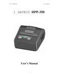
Comfortable and modern –
without trinkets
For modern cars and car owners
Table of contents
Alarm description..................................................................................... 2
Introduction........................................................................................ 2
Terms.................................................................................................. 2
Alarm feature...................................................................................... 2
Alarm operation algorithm.................................................................... 2
Table 1. Trigger diagnostics.................................................................. 3
PINTODrive® feature........................................................................... 3
AntiHiJack feature................................................................................ 3
PIN-code............................................................................................. 4
PUK-code............................................................................................ 4
Maintanence mode............................................................................... 4
Additional features............................................................................... 5
Connection.............................................................................................. 5
Inputs/Outputs of the alarm................................................................. 5
Table 2. Alarm main connector description............................................ 5
Table 3. 4-pin connector description..................................................... 6
Table 4. LED connector description....................................................... 6
Alarm connection scheme (Factory settings)......................................... 7
Alarm programming................................................................................. 7
Programming stage one ...................................................................... 7
Interfacing alarm with the vehicle...................................................... 7
Programming stage two ...................................................................... 8
Hardware features configuration........................................................ 8
Table 5. Programming menu.............................................................. 8
Hardware features configuration ("Menu 1").............................................8
Table 6. Hardware features configuration ("Menu 1").......................... 8
Table 7. Alarm programmable outputs................................................ 9
Table 8.Programmable inputs features.............................................. 10
Alarm user settings.......................................................................... 11
Table 9. User settings ("Menu 2")..................................................... 11
Programming sequence...................................................................... 12
PIN code changing............................................................................. 12
Programming button changing........................................................... 12
Programming examples...................................................................... 13
Resetting to factory default settings................................................... 13
Resetting to factory default settings....................................................14
Standard delivery kit.............................................................................. 15
Technical data and operation conditions................................................. 15
Alarm description
Introduction
This Technical Manual is applicable for the following Slave alarm
systems: Prizrak-700 & Prizrak-710, (hereinafter referred to as Alarm).
Immobilizer and AntiHiJack features are available only in
"Prizrak-710"
The Alarm is designed for protecting the vehicle from being stolen
from parking location and from being hijacked. The Alarm also
notifies
should the vehicle be tampered with while it is parked.
In order to receive information on Alarm connection to a given vehicle
and on the list of vehicles compatible with the Alarm along with
information on its functionality please use Integrator files installation
data (hereinafter referred to as Integrator files).
Starting from v 6.4.xxx the alarm supports underhood
module HCU-230.
Terms
Programming button — one of original buttons of the vehicle
used for programming the Alarm (see Integrator files for information
on which button is used in each given vehicle). When using the
Alarm, the Programming button is not redefined. The button can be
redefined only during the installation of the Alarm in the vehicle.The
button integrated in the Alarm’s case can be used as Programming
button. (see Fig. 2).
Security — it is the condition of Alarm that is entered by locking the
vehicle’s doors in any way provided by the vehicle manufacturer (with the
lock cylinder on driver’s door, keyless access system, remote control, or
re-arming etc.) that includes arming of the original vehicle alarm. Secure
condition is left by unlocking the doors with the original remote control or
vehicle keyless access system and by entering the PIN code.
Speed control — allows setting the locking activation algorithm
for Immobilizer and AntiHiJack features. Speed control can be activated
and de-activated in user settings programming menu. Certain vehicles
may not support this feature (please see Integrator files for details).
Guard mode — is an active operation mode of Immobilizer and
AntiHiJack features: should one of these features enter the Guard
mode, it is necessary to enter the correct PIN code; otherwise the
Engine locking will occur.
Comfort feature — is the original function that allows not only
locking vehicle’s doors but also close the vehicle’s windows (possibly
with the roof insert) with the original remote control and (or) with the
key).
Alarm features
◊ Theft protection when the vehicle is parked (immobilizer
feature)
◊ Hijacking protection (AntiHiJack feature)
◊ Audible and light notifications on alarm triggering
◊ Engine locking
◊ Accessory sensors connection: tilt, volumetric etc. (shock
sensor is included in standard delivery kit)
◊ Trunk opening without disarming
◊ Automatic windows closing when arming
◊ Central locking system activation
Alarm operation algorithm
Arming / disarming
To arm the alarm press the button of the remote, or close the
doors with keyless system or lock the door with the key. Alarm will
warn you that it is armed with audible signal and LED flashes. After
some time interval between flashes will decrease.
To disarm the alarm press button of the remote, or open vehicle
with keyless system. Alarm will warn you with 2 audible signals. LED
will go off.
Emergency disarming
If remote is unavailable (low battery charge for example), then to
disarm the alarm do following:
1 Open drivers door with key. Alarm will be triggered
2 Turn the ignition on and enter PIN code, enter confirmation.
Alarm will be disarmed.
Open door warning
If you left door, hood, or trunk open, the system will warn you with 3
audible signals. LED will flash indicating open compartment:
2
◊ 2 flashes — open trunk
◊ 3 flashes — open trunk
◊ 4 flashes — open door (doors).
Alarm won’t warn you when vehicle is accesed through unopened
door. You can, without rearming, close door, hood, or trunk, and the
system will take it under its control.
Alarm trigger
In the Security mode, the Alarm can react to actions with your
vehicle in two ways: Warning and Alarm. The Warning triggers when
there are weak effects on the shock sensor, e.g. due to vibrations
caused by passing transport. In this case the siren emits several
short signals. Alarm signal is activated if any door, hood or trunk were
opened and when there was a strong effect on shock sensor. Siren will
be on for 30 seconds and hazard lights will blink
You can adjust sensors sensitivity
TEC-61150-21 Technical Description Prizrak-700; 710
Public order feature
After three triggers in armed mode from one sensor in one hour
alarm will stop responding to this sensor for one hour. Alarm will.
continue working with this sensor if there were no triggers for one
hour. This function will cancel alerts but warnings will stay.
Triggger check
Alarm remembers causes of alerts for security period. Memory will
be cleared after ignition switched on.
If alarm was triggered, after disarming the alarm four audible
signals will be made and indcation of cause will start.
Table 1. Trigger diagnostics
LED flashes
x2
x3
x4
x5
x6
x7
x8
x9
Trigger cause
Hood
Trunk
Doors
Sensor
Sensor
Sensor
Sensor
"Public
1 Trigger’
2 "Trigger"
1 "Warning"
2 "Warning"
order feature"
Arming the alarm in sensor off mode
If you would like to turn audible alert off:
◊ Arm the alarm
◊ In 3 seconds press button of the remote, siren will make one
long audible signal, then pause and one short signal— warning
mode will switch off. Alarm will not react to warning trigger
from sensors
◊ In next 3 seconds press
button again — siren will make
song signal, then pause and 2 more signals — all sensors will
switch off.
Trunk opening without leaving the security mode
You can open the trunk with remote or keyless system While trunk is
open alarm will stop reacting to sensor input, but will control doors so
the vehicle will stay secured from intrusion. After trunk is close the
system will secure it and turn all sensors back on.
Disarming with PIN code
Alarm can be set up so it requires PIN code to be entered to be
disarmed. If PIN code wasn’t entered in 30 seconds after opening any
door, trunk, or hood.
PIN code is required only if alarm was armed for more than 30
seconds. To turn the alert off enter PIN code.
"PINTODrive" feature
"PINTO Drive®" — is a feature designed to prevent vehicle from
being stolen from parking space. "PIN TO Drive®" goes into effect if
ignition was switched off for more than 3 seconds. If "PIN TO Drive®"
feature is enabled and active it requires PIN code to be deactivated,
otherwise
◊ Engine will be switched off on attempt to move
◊ The engine will be turned off within 5 seconds after the
ignition has been turned on if the Speed control is off or is not
supported by the vehicle.
"AntiHiJack" feature
"AntiHiJack" — is the function that prevents the vehicle from
being hijacked or stolen from its parking area.
AntiHiJack enters the Guard mode in the following cases:
◊ The ignition has been turned off for longer than 30 seconds
(in case if Immobilizer feature was not on; if it was on thenthe
Alarm will follow its algorithms).
◊ Driver’s door has been opened.
Upon entering the Guard mode, AntiHiJack feature passes
a sequenceof phases and in case if the Guard mode has not been
deactivated,the feature will activate the Engine locking. Changing of
phases takes place only when the ignition is on. When ignition has been
turned off the Alarm will save its current condition and will continue its
operation when the ignition is back on. AntiHiJack’s Guard mode can
be deactivated at any phase by entering the PIN code. Guard mode
includes the following phases:
◊ Idle phase
◊ Alarm phase
◊ Locking phase
Idle phase. In this phase AntiHiJack follows two different algorithms
depending on the availability of Speed control.
If the Speed control is available, AntiHiJack waits until the vehicle
covers a set distance from the moment of Guard mode activation.
Upon that, AntiHiJack goes into the Warning phase. If the Speed
control is not available, Idle phase consists of three stages:
◊ Waiting for driver’s door closing
◊ Waiting for a certain number of brake pedal pressings
◊ Pause before Alarm phase initiation.
Warning phase. This phase consists of two stages:
◊ Driver warning on the necessity of entering the PIN code (10
seconds). It is carried out by audible and light signals.
◊ Warning the other drivers on the road on the possible
hazardous situation due to the upcoming engine locking (10
seconds). It is carried out by vehicle hazard lights warning the
other drivers. Audible and light signals warning the driver are
still on.
Locking phase. Engine locking is activated. Hazard lights will
be on for 15 seconds. AntiHiJack will be in the locking phase until
the PIN code is entered.
When safe locking mode is on (see Alarm hardware features
programming (Menu 1) section), Engine locking will be activated
only if the vehicle’s speed is 30 km/h or less. If the vehicle speed
exceeds 30 km/h the Alarm will wait for speed decrease for an
unlimited amount of time (while the vehicle is moving). As soon as
the speed goes as low as 30 km/h the Alarm will lock the engine
Use of safe locking mode allows mitigating the risk of collisions
when Engine locking is activated. When the ignition is off AntiHiJack
turns the hazard lights and audible driver warning signals off. If
the Immobilizer feature has not entered the Guard mode (see the
Immobilizer feature section) then, upon the next ignition activation
AntiHiJack will allow turning the engine on but will interfere with
driving as per the same algorithms as the Immobilizer feature. If the
Immobilizer feature has entered the Guard mode, then, upon ignition’s
deactivation AntiHiJack feature will stop its operation and Alarm will
follow the algorithms of Immobilizer feature..
PIN-code
PIN-code — is a secret sequential combination of original vehicle
button(s). Please see the Integrator files for the list of original buttons
perceived by the Immobilizer. PIN code needs to be entered prior
to driving the vehicle. PIN code is a one-, two-, three- or four-digit
number. Each digit is a number from 1 to 9.
TEC-61150-21 Technical Description Prizrak-700; 710
PIN code can be promptly changed numerous times by both
technical specialists during Immobilizer installation or by you during
day to day vehicle use.
To maintain proper security level PIN code has to be changed.
Until this is done signal will be emitted every factory PIN entry as a
reminder to change it
3
If you made an error during input warning trill will be made. After
trill try again.
PIN-code entry:
Factory PIN-code – 2, it has to be entered via built in button.
It is impossible to set PIN "1" – single button press
1 Turn the ignition on or start the engine
2 Enter PIN-code.
3 Wait for confirmation trill .
PIN-code examples
Buttons
,
,
,
One digit PIN-code "2":
,
— used as an example. Ask for precise list from your installer .
One button PIN‑code
2 digit PIN-code "11":
pause ~2 seconds
Multiple buttons PIN-code
Please mind button sequence.
One digit PIN-code "4":
2 digit PIN-code "22":
pause ~2 seconds
PUK-code
In case if the vehicle owner loses the PIN code, the Alarm supports
the entering of the PUK code. PUK code completely replaces the PIN
code but cannot be changed during operation. PUK code is located
under the protective layer on the plastic card. PUK code entering is
carried out by Programming button with 2-second pause after each
digit. PUK code can be entered with the integrated button and with the
original vehicle button assigned as the Programming button:
1 Turn the ignition on or start the engine.
2 Enter PUK-code.
3 Wait for confirmation trill
If you made an error during input warning trill will be made. After
trill try again
After succesfull PUK entry new PIN can be registred
Maintanence mode
Maintenance is an operation mode when all theft prevention and
service functions of the alarm are temporarily deactivated.
Alarm will warn about maintanence mode by :
◊ LED flash after disarming
◊ LED goes off if ignition switched on
◊ Warning trill after PIN-code entry
◊ Upod turning the ignition off LED flashes.
To toggle maintanence mode following should be done:
1 Turn the ignition on.
2 Enter PIN-code.
3 Press built in button 6 times (this has to be done in 10 second
frame after PIN code entry).
4 Wait for confirmation:
◊ Mode is on – 1 sound, 1 LED flash and a trill
◊ Mode is off – 2 sounds, 2 LED flash and a trill.
Automatic maintenance mode shutdown
This function will switch maintanence mode off after vehicle was
If speed control is not supported by a vehicle this function will be
driven for 10 kilometers
disabled.
If maintanence mode was switched on via built it button it will not
switch off automatically.
Additional features
The alarm has additional features , allowing to raise security level.
Automatic window closing ("Comfort")
Alarm can be programmed to close all windows after arming the
alarm. This feature is not supported by all vehicles. Please check
Integrator files.
Control of an electromechanical hood lock
The alarm allows to close hood lock when alarm is armed , and
open it with PIN-code.
Central lock control
If vehicle does not have:
◊ Door locking on move
◊ Door unlock on Ignition o
◊ This can be done with the alarm.
This feature is not supported by all vehicles. Please check
Integrator files.
Connection
Inputs/Outputs of the alarm
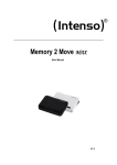
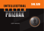
Alarm I/O is described in Tables, and pin numeration is indicated
on fig. 1. Input / Output configuration is carried out via programming
(see "Alarm hardware features programming (Menu 1)").
Figure 1. Connector pin numeration from harness viewpoint
4
TEC-61150-21 Technical Description Prizrak-700; 710
Table 2. Alarm main connector description
№
Colour
Type
Function
1
2
3
4
5
6
7
8
9
10
Green
Blue
—
Gray/Yellow
Pink/Green
Brown
White/Black
Black
Orange/Green
Green/Yellow
(-) Output
(-) Output
Not used
Analog / digital button
(+) Input
CAN
(-) Output
Power supply
(-) Output
(+) Input
Programmable negative output
Programmable negative output
—
Reference ground / Negative button
Programmable positive input
CAN-L
Engine locking / TP-BUS
Ground
Programmable negative output
Programmable positive input
11
Blue/Red
(+/-) Output
Alternate hazard lights control
12
13
14
Gray/Black
Green/Black
Brown/Red
Analog / digital button
(-) Input
CAN
Analog button / Positive button
Programmable negative input
CAN-H
15
Pink/Black
(+/-) Output
Siren control (+) / Horn control (-)
16
Red
Power supply
+12 V
1)
— Useful current of output No. 8 depends on demand connected to
negative outputs.
2)
— Typical useful current values in operation and idle modes are indicated
and may change depending on positive outputs demand.
Current, mA
150
150
—
0,5
1,5
150
—
1)
150
1,5
150/150
0,5
1,5
1300/150
1500/2
2)
Outputs No. 1, 2, 7, 9, 11, and 15 are protected from short circuit,
inductive eruptions, overheating and maximum current surpassing.
Alarm main connector contact pins description
Pin № 1, 2, 9. Programmable negative output.
Pin № 11. (+/-) output “Alternate hazard lights control”. Used to
Pin № 3. Not in use.
control hazard lights in vehicles where CAN bus is not avaliable. For list
Pin № 4. Reference ground / Negative button. Depending on control of vehicles that require this connection please refer to Integrator
button type choice one of the following functions is used:
Pin № 12. "Analog button/Positive button". Depending on chosen
◊ Reference ground: when selecting the analog control button it control button type one of the following functions is used:
is connected to the corresponding vehicle wire (see Integrator
◊ Analog button is connected to the corresponding vehicle wirу
files)
at the steering wheel
◊ Negative button: is connected to negative (controlled by
◊ Positive button is connected to the positive button (the one
making contact with the ground) button. It is used in case if
controlled by +12V voltage). It is used in case if there are no
there are no original buttons perceived by the Alarm.
original vehicle buttons perceived by the Immobilizer.
If the vehicle has original buttons controlled via CAN bus that are
If the vehicle has original buttons controlled via CAN bus that are
perceived by the Alarm, this input may be unused.
perceived by the Immobilizer, this input may be discarded.
Pin № 5, 10. Programmable positive inputs.
Pin № 13. (-) programmable negative input.
Pin № 6, 14. "CAN-L. CAN-H vehicle data bus". Connects to vehicles
Pin № 15. Siren control / Horn control. Required algorithm
CAN bus.
is set when installing the Alarm (see Alarm hardware features Pin № 7. Engine locking / TP-BUS. It is connected to the engine programming (Menu 1)).
control relay.
Pin № 16. Alarm power supply. It is connected through 3A fuse to
Pin № 8. Ground. Connects to the vehicles body in the area any non-switched circuit.
determined by vehicle manufacturer for OEM connection.
Table 3. 4-pin connector description
№
Colour
Type
Function
1
2
3
4
Red
Black
White
Blue
Power
Power
Input (–)
Input (–)
+12V sensor power supply
Sensor power supply ground
Sensor 2 (Trigger)
Sensor 1 (Warning)
Alarm can be equipped with an additional sensor. The alam can operate with standart sensors as well as with multiplex sensors
Table 4. LED connector description
№
Colour
Type
Function
1
2
Red
Blue
Power supply
Power supply
Ground
+12V
TEC-61150-21 Technical Description Prizrak-700; 710
5
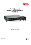
External sensors connection
The shock sensor included in the delivery kit is equipped with sec, Warning is triggered. If the signal is longer than 0.8 sec,Alarm
dedicated outputs for warning and alarm. This sensor operates is activated.
correctly in both multiplex and standard modes. Sensor connection
is carried out with a special harness supplied in the kit. No additional
programming is required..
When it is necessary to install other sensors, various connection
schemes are available, two of which are presented below. Should the
sensor with dedicated warning and alarm zones please refer to Scheme
No. A. It is necessary to use the standard sensors operation mode
(see Alarm hardware features programming (Menu 1) section). In this
scheme Sensor No. 1 has a functional purpose of warning input, while
Sensor No. 2 is the triggering input. When connecting two multiplex
sensors Scheme No. B is applied. In this case it is necessary to program
the multiplex sensors inputs operation (see Alarm hardware features
programming (Menu 1) section). In this scheme functional purposes
of sensor inputs are identical. When receiving a signal longer than 0.8
.
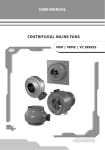
Alarm connection scheme (Factory settings)
6
TEC-61150-21 Technical Description Prizrak-700; 710
Alarm programming
Programming stage one
Programming is performed with programming button.
Interfacing alarm with the vehicle
Identifying the vehicle model
Vehicles supported by the Alarm are divided into functional groups,
each of which is divided into subgroups. All groups and subgroups are
assigned with item ordinals (see Integrator files). Interfacing is the
procedure of Alarm detecting vehicle group and subgroup.
There are two interfacing options
1 Automatic interfacing
In order to automatically interface the Alarm with the vehicle it
is necessary to carry out a set of actions (see Integrator files). Upon
vehicle identification algorithm is launched the Alarm emits a constant
audible signal.
Interfacing procedure is diffrent for every vehicle, please check
Integrator.
2 Forced interfacing
This option should be used in extraordinary cases
Programming is carried out with the bultin button. Prior to
interfacing procedure initiation vehicle group must not be identified
and CAN bus must not be connected. Programming will stop if
Programming button not pressed for 60 seconds.
Programming sequence:
1 Power the Alarm and wait for discontinuous audible and light
signal.
2 Enter Menu 1 by pressing the Programming button 10 times
(this needs to be within 10 seconds after the system has been
powered). If the procedure is carried out correctly, the Alarm
will inform on this fact with three audible and light signals.
3 Enter menu option #1 – Vehicle model – by pressing the
Programming button once. The Alarm will inform on option
condition with 1 audible and 1 light signal series.
4 Enter the vehicles group number by pressing the Programming
button for the corresponding number of times (see Integrator
files). The Alarm will emit series of audible and light signals
where the number of signals corresponding with the group
number.
If group is 2 digit number – enter first digit of the group, wait
for 2 seconds and enter second digit of the group number.The
Alarm will emit series of audible and light signals corresponding
with the group number.
5 Enter the vehicle’s subgroup number by pressing the
Programming button for the corresponding number of times
(see Integrator).
Verify that the vehicle model has been chosen correctly with
help of audible signals:
◊ If everything is corrent, press programming button once.
Audible signals will stop, programming is complete
◊ If model of the vehicle was chosen incorrectly – press
programming button twice. Repeat the procedure from № 4.
Analog steering wheel buttons pogramming .
In order to use the analog steering wheel buttons please do as
follows:
1 Right after the Immobilizer identifies the vehicle model, turn
the ignition on and wait for no less than 5 seconds.
2 Press all the steering wheel (and steering wheel column)
buttons sequentially. If sound is emitted after pressing the
button, then this button is avaliable to use
3 Turn the ignition off. A trill will be made
4 Turn the ignition on.
5 Assign programming button by pressing and holding the
button for 5 seconds(wait for sound signal)/
It is nessesary initiate this procedure within 15 minutes after
interfacing the alarm with the vehicle. If 15 minutes period has
passed reset the system to default settings and reprogram the
alarm.
Programming of digital (positive and/or negative) button
To use digital button:
1 Set the alarm to work with digital buttons (см. табл. 6. "Alarm
hardware features configuration ("menu 1")", option #4;
Changes can be made only from built in button before first
entry of the pin with analog or digital buttons.
2 Assign connected button as programming button
It is nessesary initiate this procedure within 15 minutes after
interfacing the alarm with the vehicle. If 15 minutes period has
passed reset the system to default settings and reprogram the
alarm
Programming stage two
Alarm configuration programming
At stage two Alarm hardware functions and user settings are changed and a new PIN code is programmed. Three independent menus
are used during programming (see programming menu table)
Table 5. Programming menu
Name
Code
Number of
audio signals
"Menu 1"
"Menu 2"
"Menu 3"
10
12
14
3
4
1
TEC-61150-21 Technical Description Prizrak-700; 710
Function
Alarm hardware features configuration
User settings configuration
PIN code changing
7
Hardware features configuration ("Menu 1")
Programming is performed as in hardware features configuration.
Table 6. Hardware features configuration ("Menu 1")
#
Option name
Range
Factory settings
1
Vehicle model
—
—
Description
—
1–
2–
3–
4–
5–
Normally open relay
Normally closed relay
Gas pedal lock
Starter and CAN bus lock
Digital relay control (underhood module HCU-230)
2
Engine locking
1-5
2
3
Safe lock mode
1-3
1
4
External buttons type
1-2
1
5
Hazard lights control
algorithm
1-5
—
6
Siren control /
Horn control
1-2
1
Output #15 operation mode and polarity
1 – Siren control. Constant level signal (+12V)
2 – Horn conrol. Discrete negative signal.
Used to control stock horn
1-6
3
One unit is equal to 10 seconds
1-2
2
1 – multiplex external sensors operation mode
2 – standard external sensors operation mode
25
Impulse to lock the
hood
Timer channel (comfort) feature
running time
External sensors operation
mode
7
8
1 – Engine lock is speed independent
2 – Engine will be locked at 30km\h or less
3 – Engine will be locked at full stop
1)
9
Output (–) #1
1-26
10
Output (–) #2
1-26
11
Output (–) #9
1-26
23
Timer channel
("Comfort")
12
Input (+) #5
1-8
1
Brake lights state
13
Input (+) #10
1-8
14
Input (–) #13
1-8
15
Engine launch restriction
1-2
2
16
Speed control
1-2
1
17
Brake pedal presses
1-7
3
1
2
1
2
3
4
5
–
–
–
–
–
–
–
inputs #4 and #12 used as analog buttons
inputs #4 and #12 used as digital buttons
impulse negative control
status negative control
impulse positive control
status positive control
Lights control (negative)
Programmable output
("Programmable outputs features")
4
Programmable output
impulse after PIN-code ("Programmable outputs features")
7
Disable alert by trunk
state
2
Hood control
Programmable output
("Programmable outputs features")
Programmable input ("Programmable inputs features")
Programmable input ("Programmable inputs features")
Programmable input "Programmable inputs features")
1
2
1
2
—
—
—
—
Enabled
Disabled
Enabled
Disabled
—
— If hazard lights caontrolled via CAN bus, this option won’t be defined. If hazard lights are not controlled via CAN, then range is defined.
Annotations to the table
Option №1. Vehicle model. Allows forced selection of vehicle
Option №7. Timer channel (comfort) feature running time. Allows
group and subgroup.
to set the time within which Timer channel (comfort) feature
Option №2. "Engine locking". option has 4 states:
will be active. Time is set in 10 sec intervals, i.e. if the options
1 Output №7 set to control normally open relay.
setting is 3, and then the feature will be active for 30 sec.
2 Output №7 set to control normally closed relay.
Option №8. External sensors operation mode. Allows setting one
3 Output №7 set to control gas pedal lock.
of two external sensors operation modes (see External sensors
4 Output №7 set to control starter lock and diagnostic bus
connection section).
(control normally closed relay control). Constant level signal is
1 Multiplex mode for connecting multiplex sensors
formed if the bus is active to block the starter.
2 Standard mode for connecting sensors with dedicated warning
5 Output №7 set to control underhood module HCU-230.
and alarm outputs
Option №3. Safe lock mode.
Options №№ 9-11. Programmable outputs. Designed to change
1 Engine will be locked at any speed
the Alarm outputs configuration by assigning each of the
2 Engine will be locked only if speed is less than or equal to
outputs one of 25 features from Alarm programmable outputs
30km/h
features table.
3 Engine will be locked only after full stop
Options №№ 12-14. Programmable inputs. Designed to change
Option №4. External buttons type.Depending on the buttons
the Alarm outputs configuration by assigning each of the
used:
outputs one of 7 features from Alarm programmable inputs
◊ Inputs #4 and #12 are used for connecting analog (steering
table.
wheel) buttons
Option №15. Engine launch restriction. If enabled engine cannot
◊ Inputs #4 and #12 are used for connecting digital (positive\
be launched without PIN code.
negative) buttons.
Option №16. Speed control. Changes operation settings for
Option №5. Hazard lights control agorithm. In the majority of cases
PinToDrive and AntiHIJack.
the algorithm is set automatically during vehicle interfacing.
Option №17. "Brake pedal presses". Changes amount of brake
Option №6. Siren/horn control. Allows setting output #15 for
presses required for AntiHiJack to activate. If Speed control is
emitting the Alarm signal to the vehicle’s original horn.
active this option won’t affect anything.
1)
8
TEC-61150-21 Technical Description Prizrak-700; 710
Table 7. Alarm programmable outputs
Feature
Name
#
1
Security
2
Arming impulse
3
Disarming impulse
4
PIN code entering impulse
5
Stock security system
panic
6
Siren panic
Description
Constant level signal is formed while the Alarm is in Security mode.
0.8 second long impulse is formed when Alarm is entering the Security mode, an impulse is also formed
when AntiHiJack feature is triggered.
0.8 second long impulse is formed when Immobilizer is leaving the Security mode.
0.8 second long impulse is formed when the correct PIN code is entered. The impulse is also formed in
Maintenance mode 1 second after the ignition has been turned on even if the PIN code had not been
entered.
Constant level signal is formed while the original vehicle alarm (if the vehicle is equipped with it) is in
Alarm condition.
30 seconds long constant level signal is formed if one of the following zones is triggered while the vehicle
is in Security condition: doors, hood or trunk opening. The function can be applied in vehicles that are not
equipped with original alarm system. The signal stops when vehicle is not in Security mode any longer..
30 seconds long constant level signal is formed if one of the following zones is triggered: doors, hood or
trunk opening. The function can be applied in vehicles that are not equipped with original alarm system.
The signal stops when vehicle is not in Security mode any longer. This feature is used for sending an
alarm signal to the original vehicle horn.
7
Horn panic
8
Doors, hood, and trunk
9
Sensors ignoring
Constant level signal is formed when the trunk is open in Security mode if the trunk has been opened
with the original remote control. Also the signal is formed for the purposes of Comfort feature. The
feature purpose is to deactivate the sensors to prevent false alarms.
10
Original buttons
Constant level signal is formed if the preset vehicle button is pressed.
11
Ignition
12
АСС
13
Engine on
14
Engine rpm
Impulse signal is formed. Its impulse sequence frequency is proportional to the engine crankshaft
rotation frequency. 1 impulse per second corresponds with 20 crankshaft rpm. The signal’s purpose is to
determine the approximate and not precise rpm value.
15
Gearbox state
Constant level signal is formed if transmission handle is set in preprogrammed position (P, R, N, and D
). For semi automatic transmission the positions are R, N, D) ; for manual transmission only R position
is available.
16
Vehicle is moving
Constant level signal is formed if the vehicle speed has exceeded a certain threshold value (depends on
a vehicle and varies in the range from 5 to 10 km/h).
Front parking sensors
activation
Rear parking sensors
activation
17
18
19
Movement speed
Constant level signal is formed if one of the doors, hood, or trunk is open.
Constant level signal is formed when ignition is turned on (including engine starting).
Constant level signal is formed when vehicle ACC are on (1st key position, may match with ignition on
certain vehicles). It is turned off only when the ignition key is out of ignition lock. Can be used for correct
accessory alarm system or multimedia system power management.
Constant level signal is formed when the engine is on.
Constant level signal is formed if the engine is on and the transmission is in D) position or R position
(for mechanical transmission only R position is available) and the movement speed is less than 15 km/h.
Constant level signal is formed if the engine is on and the transmission is in R position and the vehicle
movementspeed is less than 15 km/h..
Impulse signal is formed. Its impulse sequence frequency is proportional to the vehicle speed. 1 impulse
per second corresponds with 1 km/h speed. The signal’s purpose is to determine the approximate and
not precise speed value
Constant level signal is formed when the brake pedal is pressed.
20
Brake
21
Parking brake
Constant level signal is formed when the vehicle is on parking brake.
22
External lights
23
Timer channel (Comfort)
24
Starter and diagnostic
bus lock
25
Hood lock close impulse
Constant level signal is formed when the external lights are on..
Constant level signal is formed for a set period of time (10 to 60 seconds) upon arming. The time is set in
10-second intervals
Constant level signal is formed with the bus active prior to PIN code entry. The signal is also formed if
AntiHiJack feature has been triggered.
0.8 second long impulse is formed when Alarm is entering the Security mode, impulse is also formed if
engine is locked. Impulse will not be formed if hood is open.
26
Gas pedal lock (forced stop)
1)
Required for Safe Lock Mode to stop the vehicle if AntiHiJack feature was triggered.
— all handle positions to move forward (D, S, M, L etc.).
TEC-61150-21 Technical Description Prizrak-700; 710
9
Table 8. Programmable inputs features
№
1
Название функции
Описание функции
Brake lights state
The function is used only in case if the vehicle’s CAN bus does not contain data on brake pedal position. In
this case Brake lights state input is to be connected to brake pedal terminal switch output..
2
Hood control
3
Doors control
4
5
Central lock is closed
(state)
Central lock is open
(state)
6
Ignition control
7
Trunk alarm
8
CAN bus wake up
The function is used in case if vehicle’s CAN bus does not contain data on hood position. In this case Hood control
input has to be connected to hood’s terminal switch.
The function is used in exceptional cases when CAN bus does not contain data on doors position (see
Integrator files)
The function is used in exceptional cases when CAN bus does not contain data on central locking system
status (see Integrator files).
The function is used in exceptional cases when CAN bus does not contain data on central locking system
status (see Integrator files).
The function is used only in cases when getting the correct data from CAN bus is not available. This situation
may occur when certain vehicle circuits are blocked. In this case Ignition control input is to be connected to
the vehicle wire that has a constant level signal when the ignition is on. Connecting this input does not cancel
ignition analysis via CAN bus. Ignition is considered as turned on when data is received by any informational
channel (CAN bus or analog input).
This function is used in case if the alarm is triggered when the trunk is opened via the original remote
control and/or keyless access system. In this case Trunk alarm prohibition input is to be connected to trunk
opening feed control wire. Input control is carried out only in Security mode. When a command to open the
trunk is detected, the alarm ignores external sensors inputs and trunk terminal switch for 5 seconds (until the
trink is open). In 5 seconds after the trunk lid has been closed system turns security back on.
Function is used in extraordinary cases.
Programming sequence
1 Turn the ignition on.
6.2. Function #10 Original buttons programming algorithm
2 Enter the PIN code and wait for confirmation.
(applicable only for options #10, #11, and #12 of the Menu 1).
3 Enter Menu 1 by pressing the Programming button 10 times (you
6.2.1 With the brake pedal pressed go to option number 10
need to do this within 10 seconds after PIN code entering). The
settings. The Alarm will inform on option condition twice
Alarm will notify of menu accessed by three audible and three
with series of 10 audible and light signals, after which
light signals.
it will start emitting irregular signals. When the irregular
4 Select menu option by pressing and releasing Programming
signals are detected, press the required button while
button for the number of times corresponding with the menu
holding the brake pedal (for the list of buttons of the
option number. The Alarm will inform on menu number by series
given model, please see Integrator files). If the Alarm has
of audible and light signals
perceived the button, it will stop emitting irregular signals
5 Go to option setting by pressing and holding the brake pedal. The
and will start indicating the option setting number with
Alarm will inform you of the option setting by series of audible and
series of 10 audible and light signals. Release the brake
light signals, changing their duration.
pedal, the Alarm will indicate menu option number. If the
6 Change the option setting by pressing and releasing the
brake pedal is released prior to the button is pressed,
Programming button for the number of times necessary for
the Alarm will save its previous condition and will start
moving from the current setting number to the required setting
indicating the menu option number.
number in the option (e.g., in order to change function No. 2
6.3. Function No. 15 Transmission condition programming
(Arming impulse) with function No. 16 (Vehicle is moving) you
algorithm (applicable only for options #10, #11, and #12 of
need to press and release the Programming button 14 times. The
Menu 1).
Alarm will inform on the new option setting with series of audible
6.3.1 With the brake pedal pressed go to option number
and light signals. It is necessary to consider that during navigation
15 settings. The Alarm will inform on option state twice
in the option the first number goes after the last one. Release
with series of 15 audible and light signals, after which
the brake pedal; the Alarm will indicate the current setting and
it will start emitting irregular signals. Then change the
then the current menu option number. Now you can proceed with
transmission to the required position: P, N, D* or R
programming the next option and leave the programming mode.
(transmission handle can be set in necessary position in
6.1. Function No. 8 Doors, hood, and trunk programming
advance); for semi automatic transmission the positions
algorithm (applicable only for options No. 10, 11 and 12 of
are R, N, D*; for manual transmission only R position is
Menu 1).
available. Release and press the brake pedal again. The
6.1.1 Set any combination of doors, hood, and trunk
Alarm will stop emitting irregular signals and will start
(hereinafter reffere just as "doors"), opening of which will
indicating the option setting number with series of 15
cause the Alarm to form a signal on the programmable
audible and light signals. Release the brake pedal, the
output.
Alarm will indicate menu option number. If the brake
6.1.2 With the brake pedal pressed go to option number 8
pedal is released prior to the button is pressed, the Alarm
settings. The Alarm will inform on option condition twice
will save its previous condition.
with series of 8 audible and light signals, after which it will
7 In order to go to next menu option programming press and release
start emitting irregular audible and light signals. When the
the Programming button for the number of times necessary for
irregular signals are activated, release the brake pedal.
navigation from the required option (e.g., in order to navigate
The Alarm will continue emitting irregular signals. Open
from option #2 to option #8 in Menu 1 press and release the
the doors that are to be identified on this output, the rest
Programming button 6 times). Important note: when navigating
are to be closed (you can open the doors in advance).
menu options, the first option follows the last one.
Press the brake pedal again. The Alarm will inform on Exiting the programming mode. The Alarm will exit programming mode
option setting change with series of 8 signals and the and save all configuration settings in energy independent memory when
doors will be assigned to this output. If the brake pedal is ignition is turned off or within 60 seconds after last menu action if the
not pressed and current option programming is left, the brake pedal is released.
Alarm will save its previous condition. Release the brake
pedal and the Alarm will go to option number indication.
10
TEC-61150-21 Technical Description Prizrak-700; 710
Alarm user settings ("Menu 2")
Таблица 9. Settings menu ("Menu 2")
Option state
#
1
2
3
4
5
6
7
8
9
Description
"PIN TO Drive® " feature
"AntiHiJack" feature
Speed control trigger distance
Siren if alarm was triggered
Factory
settings
ON
ON
PIN code audio reminder
Comfort feature control
11
Volume of arm/disarm audio confirmation
12
Disarm confirmation with PIN code
LED
OFF
Sound signals
LED
Sound signals
ON
ON
1
1
OFF
OFF
Range from 1 to 10
Range from 1 to 4
2
2
ON
ON
OFF ON
OFF ON
1
1
1
1
OFF
OFF
OFF
OFF
2
2
2
2
ON
1
OFF
2
1
4
OFF
PIN code audio confirmation
ON
Maintanence mode auto deactivation
ON
Close central lock while driving
Central lock deactivation when ignition is turned off
10
On
ON
4
Range from 1 to 4
OFF ON
1
OFF
2
Annotation to the table
Option №1. "PIN TO Drive®"
feature.
Allows
turning
the
Option №6. PIN code audio confirmation. Allows to toggle audio
"PIN TO Drive®" feature on or off.
confirmation of successful PIN code entry.
Option №2. "AntiHiJack" feature*. Allows turning the AntiHiJack
Option №7. Maintanence mode auto deactivation. Allows to toggle
feature on or off.
automatic deactivation of maintanence mode.
Option №3. Speed control trigger distance allows to set distance
Option №8. Close central lock while driving. Allows to toggle
before lock (Speed control is on). The distance is set by 100
central lock.
meter sections. For example, if the option’s setting is 3, then
Option №9. Central lock deactivation when ignition is turned off.
Lock activation Distance is 300 meters.
Allows to turn on or off automatic central lock unlocking upon
Option №4. Enable siren if alarm was triggered. Allows to select
ignition deactivation.
siren operation mode:
Option №10. Comfort feature control. Allows to turn on or off
1 — Siren is off;
automatic windows closing during vehicle locking.
2 — Siren is silent on warning;
Option №11. Volume of arm\disarm audio confirmation. Allows to
3 — Warning volume is equal to arm/disarm trigger volume,
choose required volume level:
see option # 11;
1 — Silent arm/disarm;
4 — Siren is on (maximum volume).
2 — Minimum volume level;
Option №5. PIN code audio reminder. If you use Disarm
3 — Medium volume level;
confirmation with PIN code feature (#12), you can turn on
4 — Maximum volume level;
audio reminder to enter PIN code.
Option №12. Disarm confirmation with PIN code. При использовании
данной функции снятие с охраны происходит только после ввода PIN-codeа. Если PIN-code не введен, сработает тревога.
* Only for Prizrak 710\TEC - 710
Programming sequence
1 Turn the ignition on.
2 Enter PIN-code, wait for confirmation.
3 Enter settings menu, to do this press programming button 12
times (start the operation within 10 seconds after PIN-code
entry). If you did everything correctly the alarm will make 4
audio and visual signals.
4 Enter menu option by pressing programming button the same
number of times corresponding to chosen menu option. The
alarm will confirm chosen option with visual and audio signals.
5 To change option press and hold brake pedal. The alarm will
confirm chosen option state with visual and audio signals
6 To change option state press programming button amount of
times required to change option to chosen one. For example:
to change option state from to 2 to 4 button has to be pressed
twice.
TEC-61150-21 Technical Description Prizrak-700; 710
7 Release the brake pedal. Now you can program different
option or leave the programming mode.
8 To program a different menu option press programming
button number of times requiered to move from one option
to another. For example to move from option #2 ("AntiHiJack"
feature) to option #8 (Close central lock while driving) press
and programming button 6 times.
It is possible to finish programming and leave settings at any
moment by swiching the ignition off. If within 60 seconds no changes
were made and brake pedal was not pressed, the alarm will leave
settings menu. This will be confirmed by a trill
11
PIN code changing
1 Turn the ignition.
2 Enter PIN-code, wait for confirmation.
3 Press programming button 14 раз. Wait for confirmation with
1 audio and flash signals.
4 Enter new PIN-code. You can use any vehicle buttons that are
confirmed with a sound upon press.
5 Wait for confirmation with 1 audio and flash signals.
6 Repeat new PIN-code.
7 Wait for confirmation:
◊ 2 flashes and audio signal, then trill: PIN‑code was changed,
the alarm left PIN-code changing mode
◊ Sound alert means that the PIN code has not been changed.
A mistake has been made when entering the new PIN code
confirmation and it is necessary to repeat the PIN code
changing procedure starting from p. 4
8 CAN bus activation (any procedure that will cause CAN bus to
awake).
You can exit the PIN code changing mode anytime by turning the
ignition off.
It is impossible to set PIN-code "1" – one press on one button.
Change programming button
1 Reset to factory default
2 Interface the Alarm with the vehicle.
3 If analog steering wheel buttons are used please define them
(see above for the description of this procedure)
4 In order to assign any of the buttons perceived by the Alarm
as the Programming button, press the selected button and
hold it for longer than 5 seconds until a long audible signal
will be heard.
Programming button can be assigned within 15 minutes after
interfacing with the vehicle
Examples of programming
Example 1
Objective: You would like to change the factory settings of the
Alarm: set output No. 2 Engine lock to control the normally open relay.
Procedure:
1 Turn the ignition on.
2 Enter the PIN code and wait for confirmation.
3 Enter Menu 1 by pressing the Programming button 10 times. If
you have performed all actions correctly, the Alarm will notify
you of it with 3 audible and light signals.
4 According to Hardware features configuration (Menu 1) option
No. 2 Engine lock has to be selected. To do so, press and
release the Programming button 2 times. The Alarm will inform
you on chosen menu option number by series of 2 audible and
light signals.
5 Enter option No. 2 by pressing and holding the brake pedal.
The Alarm will inform you on set option by repeated double
audible and light signals because current (factory set) option
setting is normally closed relay control.
6 Select the normally open relay control by pressing and
releasing the Programming button 3 times. The Alarm will
inform you on the option state with series of audible signal
and flash
7 Exit programming mode by turning the ignition off
12
Example 2
Objective: You would like to change the factory settings of the
Alarm: to increase the AntiHiJack activation distance from 100 to 300
meters.
Procedure:
1 Turn the ignition on.
2 Enter the PIN code and wait for confirmation.
3 Enter Menu 2 by pressing the Programming button 12 times. If
you have performed all actions correctly, the Alarm will notify
you of it with 4 audible and light signals.
4 Select the programming option for setting the AntiHiJack
activation distance. According to Alarm settings menu (Menu
2) table, option #3 has to be selected. To do so, press and
release the Programming button 3 times. The Alarm will
inform you on chosen menu option by series of 3 audible and
light signals.
5 Enter option #3 by pressing and holding the brake pedal.The
Alarm will inform you on the option setting by repeated single
audible and light signals because the current (factory set)
option setting is 1 (which stands for 100 meters distance).
6 Change option #3 state by pressing and releasing the
Programming button twice, therefore increasing the option
setting by 2 (1+2=3). The Alarm will inform you on the option
setting with series of 3 audible and light signals (300 meters).
7 Exit the setting mode by turning the ignition off
TEC-61150-21 Technical Description Prizrak-700; 710
Reset to factory default settings
The Alarm has a procedure to reset to factory default state, where all vehicle settings are removed from Alarm’s permanent memory, and
PIN code and all other options are returned to factory original values..
If alarm is installed in a car:
1 Remove power supply from the Alarm
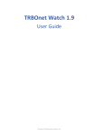
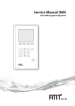
2 Press and hold the integrated button (see Fig. 2).
3 Connect the power supply while holding the button. The Alarm
will emit discrete audible signal.
4 Release the button and wait until the discrete signal stops
5 Turn the ignition on and enter the current PIN code
6 Wait for descrete signal to confirm reset to factory settings
7 Remove the power supply and disconnect the Alarm from CAN
bus.
If alarm is not installed in the vehice:
1 Press and hold the integrated button (see Fig. 2)
2 Connect the power supply while holding the button. The Alarm
will emit discrete audible signal.
3 Release the button and wait until the discrete signal stops.
4 If vehicle was not driver for more than 10 kilometer and
factory PIN-code was not changed, enter PIN-code "2" with
built in button. Otherwise enter PUK-code with built in button.
It will confirmed by a trill.
5 Wait for descrete signal to confirm reset to factory settings
6 Remove the power supply
Figure 2. Built in button
TEC-61150-21 Technical Description Prizrak-700; 710
13
Unit placement scheme
Show alarm elements on this scheme.
I’ll help you find them later
Kepp this scheme in a safe place.
14
TEC-61150-21 Technical Description Prizrak-700; 710
Package contents
Наименование
Q-ty
Central unit
Main harness
LED with harness
Shock sensor
Harness for shock sensor
Siren
Compact Disk
Reminder‑card
User manual
Warranty leaflet
Wiring manual
Packaging
1
1
1
1
1
1
1
1
1
1
1
1
pcs.
pcs.
pcs.
pcs.
pcs.
pcs.
pcs.
pcs.
pcs.
pcs.
pcs.
pcs.
Technical data and operation conditions
Parameter
Power supply voltage, V
Maximum current draw in standby mode, mA
Maximum current draw in operation mode, A
Operating temperature °C
Storage temperature °C
Maximum relative air humidity, %
TEC-61150-21 Technical Description Prizrak-700; 710
Value
9 … 15
1,5
1,5
– 40 … + 85
– 40 … + 85
95
15
WWW.CANBUS-ALARM.COM
WWW.PRIZRAK.RU
TEC electronics LTD
TEC‑61150‑21