1
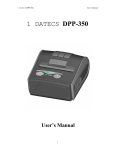
DPP-450
ESC/POS Thermal Printer
Programmer’s Manual
DATECS DPP-450
Programmer’s Manual
Introduction
DATECS DPP-450 is a mobile ESC/POS and LABEL thermal printer. It can be used in dynamic working
conditions and its abundant built-in features allow it to be widely used for different applications. Printer can
quickly and easily print text and/or graphics, depending on customer’s needs – barcodes, logo, etc.
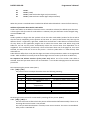
DPP-450 Specification
Printing Method
Line Thermal Dot Printing
Total Dots
832 dots / line
Dot Density
8 dots / mm (203 dpi)
Print Speed
150 mm / sec
Print Width
104 mm
Font A: 48 characters / line
Font B: 64 characters / line
Characters per Line
Font C: 48 characters / line (loadable)
Font D: 64 characters / line (loadable)
- Thermal Paper Roll: 115 mm / Ø 45 mm,
thickness 60 μm
Recommended Paper
- Label Paper Roll: 115 mm / Ø 45 mm
- RS-232C with optional special cable
(1200 – 115200 bps)
- USB 1.1 device
Interfaces
Bluetooth (option)
Wi-Fi (option)
Paper Feed system
Step
Logo Registration
1 Black & White 832 x 248 dots
Emulation
ESC/POS / LABEL (Continuous paper Mode, Black
Mark Mode)
1 D: EAN13, EAN8, UPC-A, UPC-E,
Codabar,
Code 39, Code 128
Resident Barcodes
2 D: PDF417, QR Code
Power Supply
Rechargeable battery (Li-Ion - Model ) 14.8V;
2200 mAh, Adapter: AC 100-240V, DC 24V 5A
Battery Charge Time
2 hours maximum
Input Buffer
128 KB (131072 bytes)
Reliability
50,000,000 pulses or 50 km mechanism (MCBF):
15,000,000 lines
Weight, kg
0.785 grams (w/o paper)
Dimension (Lx W x H), mm
136x 123 x 51
Operating: 0oC to +40oC; 35% RH
to 85% RH
Environment
Storage: -20oC to +60oC; 10% RH
tо 90% RH
Mobile
Label Peeler
Traveling sales
Retail
More features / Applications
Transportation
Receipts
Point of sales
Distribution
DATECS DPP-450
Accessories
Programmer’s Manual
Wearable built-in metal belt hook
Diagnostic information, dump mode and firmware updating
• Holding <LF> button while power on for ~ 0.5 sec (first sound signal) – short selftest.
• Holding <LF> button while power on for ~ 2.5 sec (second sound signal) – start dump mode. All input
data are printed hexadecimal and as text.
• Holding <LF> button while power on for more than 8.5 sec (fifth 4-tone sound signal) – enter firmware
updating mode.
• Holding <ON/OFF> button while power on for ~ 4 sec (first sound signal):
- If serial cable is connected (RS232 communication) – temporary forcing 9600 bps serial
speed.
- If no serial cable connected (Bluetooth or USB communication) – starting a hardware menu
for fast Bluetooth pairing info reset.
• Holding <ON/OFF> button while power on for more than 6 sec – enter hardware setup mode.
• Holding <ON/OFF> button while power off for more than ~ 1sec.
• Holding <ON/OFF> button while less than ~ 1sec, backlight is turn on for short time.
• Holding <ON/OFF> button and press <LF> button – printing WIFI info.
Page mode
New 13 commands are added in page mode, most of the old command work differently.
In standard mode the device prints the data after receiving new line command or when the line is wider
than the defined print area.
In page mode the result of incoming commands is forwarded to a reserved memory area (page). The
page place and size is defined using command ESC W. Command GS T selects the print direction in this page.
At the end the collected information is printed using one of the commands, provided for this. Commands
ESC FF and GS FF print only the currently defined page, but command ESC Z prints the area between the first
and last line containing at least one black point.
All commands except GS L and GS W work in page mode. The centering and right alignment
(command ESC a) is working in the currently defined page width.
Ruled lines
The printer has two line buffers with size the maximum printing width (paper width in standard
mode or the selected page width in page mode). When ruled lines are active, then every horizontal line of
the text line is combined with the selected ruled line buffer. Bit ‘1’ in the ruled line buffer is a black dot in
OR mode and inverts the color of the dot in XOR mode. Two commands allow the ruled line buffers to be
printed without combining with a text line.
When pressing the FEED button, no ruled lines buffer is applied.
All ruled lines commands start with symbol DC3 (ASCII code 13h). Please see command DC2 = , too .
Warning!
The ruled lines print position depends not on GS L and GS W (left margin and line width) and is
always at the beginning of the line (or at the beginning of the printable area in page mode). The printed
text and graphic change their position according these commands.
When printing 180 degrees rotated lines (command ESC { 1) ruled lines buffers are not rotated!
DATECS DPP-450
Programmer’s Manual
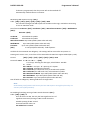
List of commands
1
2
3
4
5
6
7
8
9
10
11
12
13
14
15
16
17
18
19
20
21
22
23
24
25
26
27
28
29
30
31
32
33
34
35
36
37
39
40
41
42
43
44
45
46
47
48
49
BEL
HT
LF
FF
CR
DC2 =
DC3
DC3 +
DC3 DC3 A
DC3 B
DC3 C
DC3 D
DC3 F
DC3 L
DC3 M
DC3 P
DC3 p
DC3 v
CAN
ESC FF
ESC RS
ESC SP
ESC #
ESC $
ESC %
ESC &
ESC !
ESC *
ESC +
ESC ESC .
ESC 2
ESC 3
ESC <
ESC =
ESC >
ESC @
ESC CAL
ESC D
ESC E
ESC F
ESC G
ESC I
ESC J
ESC L
ESC N
ESC R
Sounds the buzzer
Horizontal Tab command configuration flags 2, 3 and 4
Printing а line and Paper Feeding command
Printing and paper feeding to the black mark position
The operation of the command depends on the state of the
Image LSB/MSB select
( DC3 (Ruled line) commands sequence start
Sets the ruled line ON
Sets the ruled line off
Selects ruled line A
Selects ruled line B
Clears selected ruled line buffer
Sets a single dot in selected ruled line buffer
Ruled line pattern set
Ruled line line set
Selects ruled line combine mode
Ruled line 1 dot line print
Ruled line n dots line print
Ruled line image write
Canceling print data in page mode
Printing data in page mode
Sounds the buzzer
Setting character spacing
Setting EURO symbol position
Specifying the absolute horizontal position of printing
Selecting/Canceling the printing of downloaded user character sets
Selecting user character set
Specifying printing mode of text data
Printing graphical data
Switchs OFF the printer
Selecting/Canceling underlining
Printing self test/diagnostic information
Specifying 1/6-inch line feed rate
Specifying line feed rate n/203 inches
Changes print direction to opposite
Data input control
Selecting print direction
Initializing the printer
Black mark mode sensor calibration
Setting horizontal tab position
Specifying/Canceling highlighting
Filling or inverting the page area in page mode
Specifying/Canceling highlighting
Specifying/Canceling Italic print
Printing and Paper feed n/203 inches
Selecting page mode
Reading programmed serial number
Selecting country
DATECS DPP-450
50
51
52
53
54
55
56
57
58
59
60
61
62
63
64
65
66
67
68
69
70
71
72
73
74
75
76
77
78
79
80
81
82
83
84
85
86
87
88
89
90
91
92
93
94
95
96
97
98
99
100
ESC S
ESC T
ESC U
ESC V
ESC W
ESC X
ESC Y
ESC Z
ESC \
ESC ]
ESC ^
ESC _
ESC `
ESC a
ESC b
ESC c5
ESC d
ESC i
ESC o
ESC pair=
ESC pwd=
ESC r
ESC s
ESC u
ESC v
ESC x
ESC y
ESC {
GS FF
GS $
GS )
GS *
GS /
GS :
GS B
GS C
GS H
GS L
GS Q
GS R
GS S
GS T
GS U
GS W
GS X
GS Z
GS \
GS ^
GS c
GS f
GS h
Programmer’s Manual
Specifying speed (bps) of the serial port
Printing short self test
Selecting/Canceling underlined printing
Selecting/Canceling printing 90°- right turned characters
Defining the print area in page mode
Specifying max printing speed
Selecting intensity level
Returning diagnostic information
Specifying relative horizontal position
Loading the default settings stored in Flash memory
Saving current settings in Flash memory
Loading factory settings
Reading the Battery Voltage and Thermal head temperature
Aligning the characters
Increasing text line height
Enabling/Disabling the functioning of the button LF
Printing and feeding paper by n- lines
Feeding paper backwards
Temporarily feeding paper forward
Enabling/Disabling PAIRING info saving in Bluetooth mode
Programming a new Bluetooth password (PIN)
Full command for sounding buzzer
Reading printer settings
Selecting code table
Transmitting the printer status
Setting the time interval for automatically switching Off the printer
Setting USB response strings
Enabling/Canceling printing of 180° turned characters
Printing in page mode and returning to standard mode
Specifying the absolute vertical position in page mode
Setting printer flags (memory switches)
Defining a Downloaded Bit Image (logo)
Printing a Downloaded Bit Image
Starting/ending macro definitions
Enabling/Disabling inverse printing (white on black)
Read the Real Time Clock
Selecting printing position of HRI Code
Setting the left margin
Printing 2-D barcodes
Filling or inverting a rectangle in page mode
Selecting 2-D barcode cell size
Selecting the print direction in page mode
Selecting standard mode
Setting the print area width
Drawing a rectangular box with selected thickness in page mode
Printing the non blank page area only in page mode
Specifying the relative vertical position in page mode
Executing macro
Setting the Real Time Clock
Setting the font of HRI characters of the barcode
Setting the height of the barcode
DATECS DPP-450
101
102
103
104
105
106
107
108
109
110
111
112
113
GS k
GS p
GS q
GS w
GS x
FS !
FS &
FS FS .
FS C
FS S
FS W
ESC y WAN
Programmer’s Manual
Printing a barcode
Settings for 2D barcode PDF417
Selecting the height of the module of 2D barcode PDF417
Selecting the horizontal size (Scale factor) of the barcode
Direct text print in page mode
Specifying printing mode of two-byte text data
Selecting two-byte text mode (JIS or GB2312)
Selecting/Canceling underline mode for two-byte text mode
Canceling two-byte text mode
Selecting Shift-JIS mode (Japanese version only)
Specifying character spacing for two-byte text mode
Selecting double size characters for two-byte text mode
WAN
Command Details
1. Sounds the Buzzer (BEL)
Code: [07h]
By executing this command the buzzer will beep
2. Horizontal Tab command (HT)
Code: [09h]
Shifts the printing position to the next horizontal tab position. The horizontal tab position is set by
ESC D.
By default the horizontal tab position is at each 8th character (in 9th, 17th, 25th column) from FONT
A.
3. Printing a line and Paper Feeding command (LF)
Code: [0Ah]
Prints data stored in input buffer and feeds paper with one line (the height of a line that has been
set).
4. Printing and Paper Feeding to the black mark position (FF)
Code: [0Ch]
This command prints the data in the printer buffer and searches for black mark. It is ignored if black
mark mode is not specified.
Note for Black Mark Function
-
Error detection at black mark mode
Paper end is not checked during printing and also black mark is not checked.
After receiving FF command, printer checks black mark and paper end. Once black is detected and
white is detected again within 6 mm paper feed, it is determined as black mark. If the white is not
detected within 6 mm paper feed, it is determined as paper end.
After receiving FF command, if printer cannot detect black mark by feeding paper for 360 mm,
printer recognizes it as black mark detecting error. And the result is same as detecting paper end.
To release the error, it is necessary to put correct paper and press LF switch long.
-
LF switch operation in black mark mode
Press short: Feed one line
DATECS DPP-450
Programmer’s Manual
Press longer than 1 sec.: Feed paper to find next black mark.
(Same as sending FF command)
-
Remarks for programming
As it is possible to print on black mark, if user does not want to print on the black mark, it have to be
taken care by user side program
-
Remarks on handling
If the paper cover is open in black mark mode, there is a possibility to recognize it as detecting black
mark.
5. The operation of the command depends on the state of the configuration flags 2, 3 and 4 (CR)
Code: [0Dh]
This command is ignored or its action is the same as LF depending on the state of memory switches
2, 3 and 4, set using last command GS ).
6. Image LSB/MSB select (DC2 =)
Code: [12h] + [3Dh] + n
The command selects whether the left edge of print image is the LSB or MSB for commands GS *,
DC3
F and DC3 v. n is from 0 to FFh, but only least significant bit checked:
0: LSB is the left edge.
1: MSB is the left edge.
Default is 1.
7. DC3 (Ruled line) commands sequence start (DC3 ( )
Code: [13h] + [28h]
Following this command the printer receives DC3 commands without DC3 symbol at the beginning.
The symbol ‘)’ ends the sequence. All commands, which are not DC3 commands, are ignored.
8. Sets the ruled line ON (DC3 +)
Code: [13h] + [2Bh]
After receiving this command every printed line is combined with the selected ruled line buffer. This
happens when commands LF, ESC J, ESC d, DC3 P, DC3 p are executed. Depending on last command
DC3 M executed the ruled line buffer is combined with the text using OR (if there is a bit ‘1’ in ruled
line buffer, a black dot is printed) or XOR (if there is a bit ‘1’ in ruled line buffer, then the
corresponding dot is inverted).
All DC3 command except DC3 P and DC3 p are executed when ruled line mode is off, too. Su the
ruled line buffers can be cleared or set before this command.
The command DC3 – sets ruled lines off.
In page mode nothing is printed outside the selected using ESC W region.
The command does not clear rule line buffers.
By default ruled lines are disabled.
9. Sets the ruled line OFF (DC3 -)
Code: [13h] + [2Dh]
The command disables ruled line mode.
All DC3 command except DC3 P and DC3 p are executed when ruled line mode is off, too. Su the
ruled line buffers can be cleared or set after this command.
The command DC3 + sets ruled lines on.
The command does not clear rule line buffers.
By default ruled lines are disabled.
DATECS DPP-450
Programmer’s Manual
10. Selects ruled line buffer A (DC3 A)
Code: [13h] + [41h]
Makes ruled line buffer A active.
All DC3 commands for clearing or setting data use the active ruled line buffer. When ruled line is
enabled, then printing a line and commands DC3 P and DC3 p use this buffer.
By default buffer А is selected.
11. Selects ruled line buffer B (DC3 B)
Code: [13h] + [42h]
Makes ruled line buffer B active.
All DC3 commands for clearing or setting data use the active ruled line buffer. When ruled line is
enabled, then printing a line and commands DC3 P and DC3 p use this buffer.
By default buffer B is selected.
12. Clears selected ruled line buffer (DC3 C)
Code: [13h] + [43h]
Clears selected ruled line buffer (Sets all bits to 0).
After power on or command ESC @ both buffers are clear.
Entering or leaving ruled line mode (DC3 + and DC3 -) does not clear ruled line buffers.
13. Sets a single dot in selected ruled line buffer (DC3 D)
Code: [13h] + [44h] + nL + nH
Set to ‘1’ one bit of the active ruled line buffer.
The dot coordinates are nL+256*nH. Coordinates outside the printable area are ignored.
14. Ruled line pattern set (DC3 F)
Code: [13h] + [46h] + n1 + n2
The command fills the selected ruled line buffer with the data sequence n1, n2. Permitted
values: 0-FFh. Every byte sets 8 dots, last executed command DC2 = determines whether the MSB is
the left or the right side.
The existing data in the buffer are replaced with the new data.
Dots outside the printable area are ignored.
15. Ruled line line set (DC3 L)
Code: [13h] + [4Ch] + mL + mH + nL + nH
The command sets to ‘1’ the bits between to specified coordinates in the selected ruled line buffer.
The coordinates are mL+256*mH and nL+256*nH. The part of the line outside the printable area is
ignored.
16. Selects ruled line combine mode (DC3 M)
Code: [13h] + [4Dh] + n
The command selects the logical operation between the selected ruled line buffer and the print
buffer when ruled line is enabled. n is from 1 to FFh, but only the LSB is used:
0: OR operation – bit ‘1’ in ruled line buffer sets a black dot on paper.
1: XOR operation – bit ‘1’ in ruled line buffer inverts the dot.
For commands DC3 P, DC3 p and when printing an empty line the logical operation doesn’t matter.
Logical operation XOR is useful to invert the whole height of a text line (white letters on black
background).
By default OR mode is selected (value 0).
17. Ruled line one dot line print (DC3 P)
Code: [13h] + [50h]
The active ruled line buffer is printed as a single line (0.125 mm high).
DATECS DPP-450
Programmer’s Manual
If ruled line is off, then the paper is moved one line (0.125 mm) without printing.
If there are graphic or text data in the line, they are ignored (erased).
The same effect will have command ESC 3 [01h] without text or graphic data in the line.
Warning!
Because of the characteristics of thermal printing it is possible, that the quality of single horizontal lines on
the paper is not.
18. Ruled line n dot line print (DC3 p)
Code: [13h] + [70h] + nL + nH
The selected ruled line buffer is repeated on nL+256*nH lines.
If ruled line is off, then the paper is moved nL+256*nH dots without printing.
If there are graphic or text data in the line, they are ignored (erased).
The same effect will have command ESC 3 n without text or graphic data in the line (the difference
is, that the possible line height is up to 255 dots).
Warning!
Because of the characteristics of thermal printing it is possible, that the quality of single horizontal lines on
the paper is not good.
19. Ruled line image write (DC3 v)
Code: [13h] + [76h] + nL + nH + D1 + …
The command fills the selected ruled line buffer with nL+256*nH data bytes.
Possible values of data bytes: 0-FFh. Every byte defines 8 dots, last executed DC2 = determines
whether MSB is left or right side.
Selected ruled line buffer is erased and new data are written.
Dots outside the printable area are ignored.
20. Canceling print data in page mode (CAN)
Code: [18h]
The command clears the currently selected page area and sets current print position to coordinates
(0, 0) in the current page (depending on the currently selected print direction with command GS T).
The command is not valid in standard mode.
21. Printing data in page mode (ESC FF)
Code: [1Bh] + [0Ch]
The command executes a batch printout of the data, mapped in the currently selected page. The
printer continues to work in page mode and data is not destroyed, so the command may be
executed many times.
The command is not valid in standard mode.
22. Sounds the buzzer (ESC RS)
Code: [1Bh] + [1Eh]
By executing this command the buzzer will beep.
23. Setting character spacing (ESC SP)
Code: [1Вh] + [20h] + n
[0 <= n < 40h]
The rightward space amount is set in dot unit (1/203 inch unit). The initial value is n=0. When the
font size is doubled the space between characters is also doubled. Possible values are from 0 to 63
dots.
DATECS DPP-450
Programmer’s Manual
24. Setting EURO symbol position (ESC #)
Code: [1Bh] + [23h] + n
0 <= n <= FF The ASCII code of EURO symbol
This command forces the EURO symbol to appear at the selected ASCII code. So when a code table
without EURO symbol is selected, the user can use this symbol at the desired place. The original
character with this ASCII code becomes inaccessible until redefinition using the same command.
ASCII codes from 00H to 1FH disable EURO substitution and the selected code table is printed
unchanged.
Default value is 00H (EURO substitution disabled).
25. Specifying the absolute horizontal position of printing (ESC $)
Code: [1Bh] + [24h] + n1 + n2
0 <= n1 <= FF Horizontal shifting in dots (least significant byte LSB)
0 <= n2 <= 02 Horizontal shifting in dots (most significant byte MSB)
The shifting is n1 + 256*n2 dots. Specifying beyond the line end is ignored.
26. Selecting/Canceling the printing of downloaded user character sets (ESC %)
Code: [1Bh] + [25h] + n
n can be from 0 to 255, but only the Least significant bit (LSB) is important:
0 canceling selection of user characters (default characters set is chosen)
1 loaded user character set is chosen
Character set is defined by the command ESC &. The chosen character set is kept even if printer is
switched off.
27. Selecting user character set (ESC &)
Code: [1Bh] + [26h] + а + n + m + D11 + … + D(m-n+1)k
20h <= n <= m FFh
a is the number of the sub-command and can be:
0 or ‘0’: Copies internal character set A over user character set A. All parameters after the number
of the command are omitted.
1 or ‘1’: Copies internal character set B over user character set B. All parameters after the number of
the command are omitted.
2 or ‘2’: Defines a sequence of characters for Font A (12x24)
3 or ‘3’: Defines a sequence of characters for Font B (9x16)
4 or ‘4’: Defines a sequence of characters for Font B (9x16)
n is the ASCII code of the first, m ASCII code of the last of the (m-n+1) consecutive characters. When
only one symbol is defined m=n.
With Dij are described the data for the characters. Each character from Font A is defined with 48
bytes. Each character from Font B is defined with 16 bytes for subcommand 3 (the 9-th horizontal
bit is always white) and with 32 bytes for subcommand 4 (2 bytes for each horizontal row, only the
most significant bit of the second byte is used).
The data for character set (font) A is composed from left to right and from top to bottom with two
bytes for each horizontal line. From the second byte only the first nibble (the most significant 4 bits)
is valid.
Each bit defines one dot, 1 is for black, starting from the most significant bit.
Downloaded characters are valid even after switching off the printer.
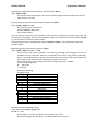
28. Specifying printing mode of text data (ESC !)
Code: [1Вh] + [21h] + n
Data is given in binary code.
Each bit of n indicates the following:
Bit
Function
Value 0
Value 1
DATECS DPP-450
0
1
2
3
4
5
6
7
Character Font
Highlighting
Double Height
Double Width
Underline
Programmer’s Manual
А (12x24)
Undefined
Undefined
Canceled
Canceled
Canceled
Undefined
Canceled
B (9x16)
Specified
Specified
Specified
Specified
An underline is attached to the full character width, which, however, is not attached to the part
having been skipped by the horizontal tab. Neither is it attached to 90°-right-turned characters.
The underline width is as having been specified by (ESC -). (The default setting is 1 dot width.)
Highlighting is valid for character font A (12x24) and font B (9x16). It is not recommended to be used for
font B because text is not readable. If at same time are given double height and/or double width and to 90°right-turning of character, then the sequense of execution is as follows:
- characters is doubled in the direction indicated,
- character is turned at 90°-right-angle.
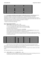
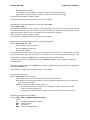
29. Printing graphical data (ESC *)
Code: [1Bh] + [2Ah] + m + n1 + n2 + D1+ … + Dk
m (0 ,1 ,20h или 21h) Graphics mode (see table below).
0 <= n1 <= FFh specifies the number of dots in horizontal line (LSB).
0 <= n2 <= 09h specifies the number of dots in horizontal line (MSB).
Di (i from 1 to k) bit image data.
The number of dots in horizontal direction is n1+n2*256.
Number of data bytes k is n1 + 256*n2 for modes 0 and 1, and (n1+256*n2)*3 for 20h and 21h.
The bits subject to printing are taken as “1” and those not as “0”.
Bit image data is sent starting from the top to bottom and from the left to right (vertical columns
scanning). In modes m=0 and 1 only one byte per column is sent and in mode m=20h, 21h - 3 bytes
for each column are sent.
m
0
1
20h
21h
Mode
8-dot single density
8-dot double density
24-dot single density
24-dot double density
Vertical Direction
Dots
Dot density
8
67 DPI
8
67 DPI
24
203 DPI
24
203 DPI
Horizontal Direction
Dot density
Max. dots 104 mm
101 DPI
Up to 416
203 DPI
Up to 832
101 DPI
Up to 416
203 DPI
Up to 832
When the values set in m or n2 are out of the above range, the data is processed as normal
printing data. If some part of the graphic or the entire graphic is outside the printable area, then graphics
data are accepted, but only the needed part of them are printed.
In page mode and rotated by 90 degrees page the max. dot count is larger than the numbers in the table
above.
This command has one more version with 3 new modes:
Code: [1Bh] + [2Ah] + m + n + { a + [00h] } +D1 + … +Dk
Designates a bit image of n*8 dots horizontal and by 24 or a dots vertical. Depending on m there is
compression of data. All 3 modes are with high dot density (203x203 dpi).
DATECS DPP-450
Programmer’s Manual
m can be:
10h Not compressed data with height 24 lines. Byte a and byte 00h are not sent.
11h Compressed data with height 24 lines. Byte a and byte 00h are not sent.
12h Compressed data with height a lines (a<=24).
0 <= n <= FFh defines horizontal size.
Di are the bit image data. Their number is n*24 bytes for mode 10h. The compressed data in mode
11h must give same number of bytes, but after the decompression. The number of data bytes for
mode 12h must be a*n (after decompression).
Decompression in modes 11h and 12h is similar to the one used in PCX monochrome graphic mode.
If the 2 most significant bits of the consecutive byte are 1, so the next define a counter of iterations
from 0 to 63, and the next byte contains the data that has to be repeated. If at least one of the most
significant bytes is 0, the byte contains data which is directly used. If the data for the printer
contains a byte with two most significant bits 1, it has to be sent as 2 bytes with counter 1.
Data for both modes is sent horizontally, from right to left and from top to bottom. Each byte
contains 8 points, the “1”-s are black starting from the most significant bit.
A new mode for printing vertical lines added in version 1.39.
Code: [1Bh] + [2Ah] + [18h] + L + n + R
L Offset (white dots) before the vertical line. From 0 to 255.
n Vertical line thickness in dots. From 0 to 255.
R Offset (white dots) after the vertical line. From 0 to 255.
The command prints a vertical black line with thickness n and height – the whole height of the line
(including the space between the lines set with commands ESC 2, ESC 3 or ESC J). The printer adds L
dots to the current X coordinate, draws the line and adds R dots to the X coordinate after the line.
The purpose of the command is to draw tables independent of the type or of the font of the printed
symbols
between the vertical lines.
Starting from version 1.40 two new modes for printing graphics are added.
Code: [1Bh] + [2Ah] + [13h] + n1 + n2 + a +D1 + … +Dk
or [1Bh] + [2Ah] + [14h] + n1 + n2 + a +D1 + … +Dk
n1 Lower part of bytes count in horizontal direction. From 0 to 255.
n2 Higher part of bytes count in horizontal direction. From 0 to 1.
a Vertical size of the image in dots. From 1 to 24.
For command ESC * [13h] data for a bit image with size (n1+256*n2)*8 dots horizontally and a dots
vertically are sent, with data compression (exactly as in command ECS * [12h]). The graphics mode
is single density (203x203 dots/inch).
Data bytes count is a*(n1+256*n2) after decompression.
For command ESC * [14h] data are without compression like ESC * [10h] command.
The commands are added to make printing of graphics in page mode easier – in page mode with
page height more than 2040 dots and print direction 90 or 270 degrees it is not possible to fill the
whole page height using only one of the older commands for compressed graphics (ESC * [11h] and
ESC * [12h]).
30. Switch’s OFF the printer (ESC +)
Code: [1Вh] + [2Bh]
This command switches OFF the printer as by setting the power switch to OFF.
31. Selecting/Cancelling Underline (ESC -)
Code: [1Bh] + [2Dh] + n
An underline is attached to the full character width. It is, however, not attached to the part having
been kipped by horizontal tab command.
DATECS DPP-450
Programmer’s Manual
An underline is not attached to a 90°- right-turned characters.
The following values of n are possible:
0 or 30h Canceling an underline.
1 or 31h Specifying an underline for 1-dot width.
2 or 32h Specifying an underline for 2-dots width.
Note:
This command only selects the underline thickness. For specifying/canceling the Underline mode
command ESC ! ([1Bh] + [21h]) must be used.
32. Printing Self Test/diagnostic information (ESC .)
Code: [1Вh] + [2Еh]
Prints test page and self-diagnostic information. The self-diagnostic information includes print
density, print head temperature, battery voltage, baud rate in case of work via RS232 and others.
33. Specifying 1/6-inch line feed rate (ESC 2)
Code: [1B] + [32h]
If in the line there are symbols that will not fit in the defined size, the line automatically is set to be
of the necessary height so they fit.
34. Specifying line feed rate n/203 inches (ESC 3)
Code: [1Bh] + [33h] + n
n is from 0 to 255.
Default value is n=22h (1/6 inches).
35. Changes print direction tо opposite (ESC <)
Code: [1Bh] + [3Ch]
The command changes current print direction. It is needed when using Hebrew and Arabic code
tables, but is working for all code tables.
Default print direction is from right to left for code tables 19, 21, 22, 23, 24 and from left to right for
all others.
The command is supported starting from version 1.42.
36. Data input control (ESC =)
Code: [1Bh] + [3Dh] + n
n can be from 0 to 255, but only the LSB is of significance.
Value 0: Printer is not selected.
Value 1: Printer is selected.
When the printer is not selected, it does not accept data (abandons all the received data) and the
only command that it executes is ESC = n with least significant bit 1.
By default the printer is selected.
37. Select print direction (ESC >)
Code: [1Bh] + [3Eh] + n
Possible values for n:
0 or ‘0’: Default direction for the selected code table.
1 or ‘1’: Left to right direction forced.
2 or ‘2’: Right to left direction forced.
The command sets the print direction. It is needed when using Hebrew and Arabic code tables, but
is working for all code tables.
Default print direction is from right to left for code tables 19, 21, 22, 23, 24 and from left to right for
all others.
DATECS DPP-450
Programmer’s Manual
Commands ESC < and ESC > work together. The sequence, which selects the direction, is as follows:
• The print direction is set according to the currently selected code table.
• If command ESC > with argument > 0 was executed since last ESC u command, then this is
the print direction.
• If command ESC < was executed after this, the print direction is changed to the opposite.
39. Initializing the printer (ESC @)
Code: [1Bh] + [40h]
Clears data stored in the print buffer and brings various settings to the initial state (Default state).
Data (items) in serial buffer are not cleared.
40. Black mark mode sensor calibration (ESC CAL)
Code: [1Bh] + [43h] + [41h] + [4Ch] + n
Selects the ADC value, which the printer uses to distinguish the black marks on paper or labels. The
command is used in black mark mode only.
Possible values for n:
- 01h Returns one byte, which is the current ADC threshold value.
- 02h After receiving this command the printer moves approximately 20 cm of paper and searches
minimum and maximum of paper sensor values. Two bytes data are returned – minimum value and
maximum value.
- 03h After receiving this command the printer moves approximately 20 cm of paper and searches
minimum and maximum of paper sensor values. Then a reasonable value of the ADC threshold is calculated
and stored in flash memory. One byte data is returned, which is the new ADC threshold value.
- 0Ch Set / Get number of steps (1/8mm) between detection of black marker and printer stop. After
receiving this command, the printer expect one more byte:
- 01h Returns one byte, which is the current number of steps (1/8mm).
- 10h to FFh The byte is used as number of steps (1/8mm) between detection of black marker and printer
stop and is stored in flash memory. One byte data is returned, which is the new value.
The factory setting of steps is 75h.
- 0Ch Peeler sensor calibration. After receiving this command, the printer expect one more byte:
- 01h Returns one byte, which is the current ADC threshold value.
- 10h to FFh
The byte is used as ADC threshold value and is stored in flash memory. One byte
data is returned, which is the new ADC threshold value.
The factory setting of ADC threshold value is B0h.
- 05h Set / Get number of steps (1/8mm) after label was got. After receiving this command, the printer
expect one more byte:
- 01h Returns one byte, which is the current number of steps (1/8mm).
- 10h to FFh The byte is used as number of steps (1/8mm)
(with offset 10h, i.e. if 1 step is wanted it must be send like (1 + 10h)).
One byte data is returned, which is the new value (real value, without 10h).
The factory setting of steps is 24h.
- 0Eh After receiving this command, the printer need one more byte, which is the new value of DAC of the
GAP sensor. If DAC value is 0, the printer uses Black Mark sensor. Return one byte, new value of DAC.
- 0Fh Return one byte, which is current value of DAC of the GAP sensor. 0 mean printer uses Black Mark
sensor.
- 10h to FFh
The byte is used as ADC threshold value and is stored in flash memory. One byte data is
returned, which is the new ADC threshold value.
The factory setting of ADC threshold value is 68h.
Use this command carefully and only if the printer has problems in black mark / label recognition.
Note:
Use this command carefully and only if the printer has problems in black mark / label recognition.
DATECS DPP-450
Programmer’s Manual
41. Setting horizontal tab position (ESC D)
Code: [1Bh] + [44h] + n1 + … + nk + [00h]
ni is from 0 to 255.
ni indicates the number of the column from the beginning to the horizontal tab position, minus 1.
For example, to set the position at 9th column, n=8 is to be specified.
The tab position is set at position where it is “character width multiplied by ni” from the line
beginning. The character width, at this time, includes the rightward space amount. In double wide
characters, it is made double of the ordinary case.
Tab positions can be specified are maximum 32.
ESC D [00h] clears all the set tab positions. Following clearing, horizontal tab command is ignored.
42. Specifying / Canceling highlighting (ESC Е)
Code: [1Bh] + [45h] + n
n can be from 0 to 255, but only the least significant bit is of significance.
Value 0: Canceling highlighting
Value 1: Highlighting is specified
This is effective for character font A (12x24) and font B (9x16).
Note:
It is not recommended to be used for font B because text is not readable.
43. Filling or inverting the page area in page mode (ESC F)
Code: 1Bh] + [46h] + n
Allowed values for n:
0 or ‘0’: The area is cleared (white)
1 or ‘1’: The area is filled (black)
2 or ‘2’: The area is inverted.
The command fills the selected with ESC W page with the desired color or inverts it. The command
is not valid in standard mode.
44. Specifying / Canceling highlighting (ESC G)
Code: [1Bh] + [47h] + n
Same as command ESC E.
45. Specifying / Canceling Italic Print (ESC I)
Code: [1Bh] + [49h] + n
n can be from 0 to 255, but only the least significant bit is of significance.
Value 0: Normal Print
Value 1: Italic Print
46. Printing and Paper Feed n/203 inches (ESC J)
Code: [1Bh] + [4Аh] + n
n can be from 0 to 255.
Prints data in the print buffer and feeds paper by n/203 inch.
• This function is temporary and does not affect the feed operation thereafter.
• The beginning of the line is to be considered as the next printing start position.
47. Selecting page mode (ESC L)
Code: [1Bh] + [4Ch]
The command switches from standard mode to page mode. In this mode the printing is not
immediately, but is accumulated in a reserved for this purpose memory area. The resulting image is
printed using one of the commands ESC FF, GS FF or GS Z.
DATECS DPP-450
Programmer’s Manual
The page area is the maximum 832x1732 dots or the result of the last executed command ESC W.
The print direction is the default (left to right) or the result of the last executed command GS T.
The current print position is (0, 0) depending on the selected print direction.
The command is not valid in page mode.
The command is supported in firmware version 1.42 or higher.
48. Reading programmed serial number (ESC N)
Code: [Bh] + [4Eh]
The command returns the programmed serial number of the printer as an ASCIIZ string. Number
length is 13 characters. If no serial number is programmed, then only one symbol is returned - 00h.
49. Selecting Country (ESC R)
Code: [1Bh] + [52h] + n
n can be from 0 o 13 and has the following meaning:
N
0
1
2
3
4
5
6
7
8
9
10
11
12
13
Character Set
U.S.A.
France
Germany
U.K.
Denmark I
Sweden
Italy
Spain I
Japan
Norway
Denmark II
Spain II
Latin America
Korea
23h 24h 40h 5Bh
#
$
@
[
#
$
à
º
#
$
§
Ä
£
$
@
[
#
$
@
Æ
#
$
É
Ä
#
$
@
º
Pt $
@
¡
#
$
@
[
#
¤
É
Æ
#
$
É
Æ
#
$
á
¡
#
$
á
¡
#
$
@
[
Changed characters
5Ch 5Dh 5Eh 60h 7Bh 7Ch 7Dh 7Eh
\
]
^
`
{
|
}
~
¢
§
^
`
é
ù
è
¨
Ö
Ü
^
`
ä
ö
ü
ß
\
]
^
`
{
|
}
~
Ø
Å
^
`
æ
ø
å
~
Ö
Å
Ü
É
ä
ö
å
ü
\
é
^
Ù
à
ò
è
ì
Ñ
¿
^
`
¨
ñ
}
~
¥
]
^
`
{
|
}
~
Ø
Å
Ü
É
æ
ø
å
ü
Ø
Å
Ü
É
æ
ø
å
ü
Ñ
¿
é
`
í
ñ
ó
ú
Ñ
¿
é
Ü
í
ñ
ó
ú
w ]
^
`
{
|
}
~
50. Specifying speed (bps) of the serial port (ESC S)
Code: [1Bh] + [53h] + n
Sets new communication speed for the serial interface.
The command is valid only when the printer is connected through a serial cable. Possible values of
parameter n:
0 or ‘0’: 1200 bps
1 or ‘1’: 2400 bps
2 or ‘2’: 4800 bps
3 or ‘3’: 9600 bps
4 or ‘4’: 19200 bps
5 or ‘5’: 57600 bps
115200
6 or ‘6’: bps
7 or ‘7’: 38400 bps
The last setting is valid after switching OFF and ON the printer.
Default value is 6 (115200 bps).
51. Printing short self test (ESC T)
Code: [1Bh] + [54h]
Prints current printer parameters, including intensity, temperature of the print head, battery
voltage, speed in case of serial connection, etc.
52. Selecting / Canceling underlined printing (ESC U).
Code: [1Bh] + [55h] + n
Possible values for n:
0 or ‘0’ Canceling underlined characters
1 or ‘1’ Specifying underlined characters
Note:
No underlines are attached to 90°-right- turned characters.
53. Selecting / Canceling printing 90° - right turned characters (ESC V)
Code: [1Bh] + [56h] + n
n can be from 0 to 255, but only the least significant bit is of
significance: 0 Canceling 90°-right- turned Characters
1 Specifying 90°-right- turned Characters
Note:
No underlines are attached to 90°-right- turned characters.
54. Defining the print area in page mode (ESC W)
Code: [1Bh] + [57h] + xL + xH + yL + yH + dxL + dxH + dyL + dyH
xL and xH Low and high byte of the horizontal offset of the relative top left corner of the
page.
yL and yH Low and high byte of the vertical offset of the relative top left corner of the
page.
dxL and dxH Low and high byte of the width of the page.
DATECS DPP-450
Programmer’s Manual
dyL and dyH Low and high byte of the height of the page.
The command defines the relative position and size of the page. In page mode the new
values are active immediately, in standard mode they are memorized and used after entering
page mode. The print position has coordinates (0, 0) depending on the currently selected
print direction (command GS T). If the relative position is invalid, the command is not
accepted. If only a part of the selected page is in the printable area (current paper width and
maximal height of 2432 dots), this area is used as page area.
Default page size is 832x1732 dots.
The command is supported in firmware version 1.42 or higher.
55. Specifying max printing speed (ESC X)
Code: [1Bh] + [58h] + n
n is between 0 and 3 or between ‘0’ and ‘3’:
0 or ‘0’
154 mm/s (6.1 inch/s)
1 or ‘1’
120 mm/s (4.7 inch/s)
2 or ‘2’
80 mm/s (3.1 inch/s)
3 or ‘3’
50 mm/s (2.0 inch/s)
Note:
The defined speed is recommended and can be achieved with not very cold printing head and
comparatively little data to print in the line (less black).
56. Specifying intensity level (ESC Y)
Code: [1Bh] + [59h] + n
n is between 0 and 6 or between ‘0’ and ‘6’:
0 or ‘0’
Intensity 60 %
1 or ‘1’
Intensity 75 %
2 or ‘2’
Intensity 90 %
3 or ‘3’
Intensity 100 %
4 or ‘4’
Intensity 120 %
5 or ‘5’
Intensity 140 %
6 or ‘6’
Intensity 160 %
Default value is 3 (100%).
Note:
Higher intensity can cause decrease in printing speed.
57. Returning diagnostic information (ESC Z)
Code: 1Bh] + [5Ah]
The printer will return 32 bytes of information with the following structure:
1-22: Printer name up to 22 charachters.
23-25: Firmware version – 3 digits.
26-27: Language version, described by two
characters.
28-32: 5 bytes with flags. When the corresponding bit is 1, the function is supported and when 0,
the function is not supported. Bits are listed below:
Bit
Meaning
DATECS DPP-450
28.0
28.1
28.2
28.3
28.4
28.5
28.6
28.7
29.0
29.1
29.2
29.3
29.4
29.5
29.6
29.7
30.0
30.1
30.2
30.3
30.4
30.5
30.6
30.7
31.0
31.1
31.2
31.3
31.4
31.5
31.6
31.7
32.0
32.1
32.2
32.3
32.4
32.5
32.6
32.7
Programmer’s Manual
Supports IrDA mode
Mag-stripe reader support
Supports reading of all 3 tracks on magnetic card
Katakana support, ASCII codes above 127 contain Katakana characters
JIS and Shift-JIS support
Prints in commands ESC . and ESC T and in command ESC ` returns temperature in º
Fahrenheit
Bluetooth support
Reserved – always is 1
Update via firmware interface
Korean characters support
BLACK MARK mode support
Barcode reader support
USB support
Not in use
Page mode support
Reserved – always is 1
GB2312 (Simplified Chinese) support
BIG5 (Traditional Chinese) support
Not in use
Not in use
Not in use
Not in use
Not in use
Reserved – always is 1
State of flag 1 – determined in command GS )
State of flag 2 – determined in command GS )
State of flag 3 – determined in command GS )
State of flag 4 – determined in command GS )
State of flag 5 – determined in command GS )
State of flag 6 – determined in command GS )
State of flag 7 – determined in command GS )
Reserved – always is 1
State of flag 8 – determined in command GS )
State of flag 9 – determined in command GS )
State of flag 10 – determined in command GS )
State of flag 11 – determined in command GS )
State of flag 12 – determined in command GS )
State of flag 13 – determined in command GS
State of flag 14 – determined in command GS )
Reserved – always is 1
58. Specifying relative horizontal position (ESC \)
Code: [1Bh] + [5Сh] + n1 + n2
0 <= n1 <= FFh Specifying number of dots from current position in
horizontal (LSB) . 0 <= n2 <= FFh Specifying number of dots from current
position in horizontal (MSB).
The printing start position is specified with n1 + 256*n2 dots. Specifying exceeding the top of
line or the end of line is ignored.
DATECS DPP-450
Programmer’s Manual
Specifying dots in minus (left) direction from the current one, is the complement of
N with 65536 (N-=65536 - N).
59. Loading the default settings stored in Flash memory (ESC ])
Code: [1Bh] + [5Dh]
- The following parameters are read from flash memory and become active:
- Speed of communication in serial port
- Time for automatic turn off
- Max printing speed
- Print density
- Height of printing line
- Country
- Code table
- Height of barcode
- Width of barcode single line
- Font of the text (HRI characters) corresponding to the barcode
- Position of the HRI characters
60. Saving current settings in Flash memory (ESC ^)
Code: [1Bh] + [5Eh]
- The values of the following settings are stored in flash memory:
- Speed of communication in serial port
- Time for automatic turn off
Max printing speed
- Print density
- Height of printing line
- Country
- Code table
- Height of barcode
- Width of barcode single line
- Font of the text (HRI characters) corresponding to the barcode
- Position of the HRI characters
These setting become default settings.
61. Loading factory settings (ESC _)
Code: 1Bh] + [5Fh]
- This command sets the printer in default state with the following settings:
- All printing attributes like underline, rotating etc. are cleared.
- Internal font A (12 x 24) is selected.
- Pitch between lines is 1/6 inch.
- Barcode height is 80 dots, and barcode width is 3.
- All downloaded fonts and bit images are cleared.
- Printing speed is set to 60 mm/s.
- Print density is 100%.
- Communication speed is set to 115200 bps.
- Code table becomes 437 (US), and country 0 (US).
For Japanese version default values are: Code table Katakana and country Japan.
62. Returning the battery voltage and printer head temperature (ESC `)
Code: [1Bh] + [60h]
DATECS DPP-450
Programmer’s Manual
Returns 2 bytes of information - the first one is battery voltage returned in the format:
battery voltage x 10 + 20H and second is head temperature returned in the format: head
temperature + 20H.
63. Aligning the characters (ESC a)
Code: [1Bh] + [61h] + n
n is between 0 and 2 or between
‘0’ and ‘2’: 0 or ‘0’ Left end
alignment
1 or ‘1’ Centering
2 or ‘2’ Right end
alignment Default
value is 0.
After printing of the line the alignment becomes automatically left-justified.
64. Increase text line height (ESC b)
Code: [1Bh] + [62h] + n
The command adds n dots to current text
line height. n is from 0 to 255.
After receiving the every symbol for printing, the printer checks its size (depending on double
height attributes, rotation e.c.t.) and sets current line height so, that the whole letter is
printed. The command adds additional dots to so calculated line height.
The maximum line height is 48 dots above base line (the line, at which the bottom of most
latin letters is, for example the letter ‘A’). If adding n to the current height is larger than
maximum height (48), then 48 is set as height.
If no text or graphic data in line, the command is not executed.
The difference between line height in commands LF, ESC 2, ESC 3 and ESC J is that the height
is increased above the letters. The command is useful when inverting a text line in XOR ruled
lines mode.
65. Enabling/Disabling the functioning of the button LF (ESC c5)
Code: [1Bh] + [63h] + [35h] + n
n can be from 0 toо 255, but only the least significant bit is of
significance. Value 0: Button LF is valid.
Value 1 : Button LF
is invalid. Default
value is 0.
66. Printing and feeding paper by n-lines (ESC d)
Code: [1Bh] + [64h] + n
n can be from 0 to 255.
Prints data inside the buffer and feeds paper by n lines.
The beginning of the line is to be considered as the next printing
start position. When n=0 paper is fed with 1 line.
67. Feeding paper backwards (ESC i)
Code: [1Bh] + [69h]
If paper has been fed forward with command ESC o, then it returns backwards. The feed is
DATECS DPP-450
Programmer’s Manual
exactly the same as it was defined in command ESC o, but in reverse direction.
If paper has not been fed forward then this command is ignored.
68. Temporarily feeding paper forward (ESC o)
Code: [1Bh] + [6Fh] + n
n can be from 0 to 255.
This command temporarily feeds paper forward with the defined number of steps n
(1/8 mm). At command ESC i or at first command for printing the paper feeds
backwards.
69. Disabling/enabling PAIRING info saving in Bluetooth mode (ESC pair=)
Code: [1Bh] + [70h] + [61h] + [69h] + [72h] + [3Dh] + n
Possible values of n:
‘0’:Disables PAIRING info
saving. ‘1’:Enables
PAIRING info saving.
After PAIRING info saving no password is required when making new Bluetooth connection,
but only paired devices can communicate. If an old connection (pairing) was saved, it will be
destroyed and first new connection will be saved in it’s place.
After executing this command with argument ‘0’ the current saved information will be
destroyed, but no new connection will be saved. Every time a password will be required. The
printer will work with all
Bluetooth devices.
After the command the printer must be switched off (using ON/OFF button or ESC x
command).
70. Programming a new Bluetooth password (PIN) (ESC pwd=)
Code: [1Bh] + [70h] + [77h] + [64h] + [3Dh] + d + [00h]
This command changes the Bluetooth module PIN.
d contains the new PIN. PIN length is from 0 to 16 characters, allowed are digits and capital
latin letters. The string ends with 00h (ASCIIZ). If the length is 0, Bluetooth module uses no
password (PIN).
New password is active after switching the printer on next time in Bluetooth mode (without
serial or USB cable). The change is unconditionally and does not require the knowledge of the
old PIN.
Warning:
The command destroys saved PAIRING info (like after command ESC pair=0).
71. Full command for sounding buzzer (ESC r)
Code: [1Bh] + [72h] + Data
This command is used for making (beeping) a sequence of sounds with a certain frequency
and duration. The data is in format, similar to the one used for writing notes and can be of
any length. The first invalid character cancels the command.
Data format: Notes of the scale: a latin letter of value
from ‘A’ to‘G’. ‘C’ - Do
‘D’ - Re
‘E’ - Mi
DATECS DPP-450
Programmer’s Manual
‘F’ - Fa
‘G’ - Sol
‘A’ - La
‘B’ – Si
If immediately after the note comes character ‘#’, then the note is higher in pitch by a
semitone (sharp). If immediately after the note comes character ‘&’, then the note is lower in
pitch by a semitone (flat).
- Pause: Character space (ASCII 20h).
After a note or pause there can be one or a few bytes, which specify the duration. Valid are
characters from ‘0’ to ‘5’, they have the following meaning:
‘0’ basic duration of a
note/pause
‘1’ basic duration * 2
‘2’ basic duration
*4
‘3’ basic duration
*8
‘4’ basic duration
* 16
‘5’ basic duration
* 32
If there are a few durations one after another they are summed up.
• Going to higher scale: character ‘+’.
• Going to lower scale: character ‘-‘.
• Specifying tempo: character ‘^’, followed by a number. The number specifies the
percentage: duration of notes and intervals to basic duration. Values:
‘1’
200 %
‘2’
175 %
‘3’
140 %
‘4’
120 %
‘5’
100 %
‘6’
80 %
‘7’
60 %
‘8’
50 %
‘9’
40 %
- Return to scale 1 (it is default). Character ‘@’. Tone ‘La’ in it is 440 Hz.
It is recommended that the data ends with ASCII code 03h, although any other non-printing
character will also stop the command.
72. Reading current printer settings (ESC s)
Code: [1Bh] + [73h] + n
This command returns current settings or loaded data in printer. Possible
values for n: 0 or ‘0’: Current settings from flash memory are returned in
following order:
DATECS DPP-450
Programmer’s Manual
• Memory switches -10 digits 0 or 1.
• Serial port speed (bauds) – an integer.
• Country number (from command ESC R) – an integer.
• Current character table (from command ESC u) – an integer.
• Print density (from command ESC Y) – an integer.
• Print speed (from command ESC X) – an integer.
• Power off time (from command ESC x) – an integer (in minutes).
• EURO symbol position (from command ESC #) – an integer from 0 to 255.
Field separator is ‘,’.
0 or ‘0’: Printer flags
1 or ‘1’: Current settings from printer RAM are returned. The format of data is the same as
for
Subcommand 0.
2 or ‘2’: The currently loaded graphic logo is returned in format:
w h Di , where:
w
Graphics width in bytes (pixels*8).
H
Graphics height in pixels.
Di
Graphics data – 2*w*h bytes in the sequence as in command GS *. Data are in
hexadecimal format (each byte sent as two hexadecimal symbols).
3 or ‘3’: Current USB strings from ESC y are returned. Format is as in command ESC y Usb,
All fields present in increasing order.
6 or ‘6’: Current WAN settings from ESC y are returned. Format is as in command ESC y WAN,
All fields present in increasing order.
73. Selecting Code table (ESC u).
Code: [1Bh] + [75h] + n
Values for n:
0
ENGLISH (437)
1
LATIN 1 (850)
2
PORTUGUESE (860)
3
LITHUANIAN
4
LATIN 2 (852)
5
POLISH
6
TURKISH (857)
7
BALTIC (775)
8
BULGARIAN (856)
9
RUSSIAN (866)
10
LATVIAN
11
GREEK (737)
12
HEBREW (862)
13
WESTERN (1252)
14
CE (1250)
15
TURKISH (1254)
16
BALTIC (1257)
17
CYRILLIC (1251)
18
GREEK (1253)
19
HEBREW (1255)
20
KATAKANA
DATECS DPP-450
21
22
23
Programmer’s Manual
ARABIC
ARABIC (1256)
ARABIC (1256 with Arabic digits and punctuation)
ARABIC (1256 with Farsi Arabic digits and punctuation)
24
When the printer is switched ON it is loaded the default code table which is stored in flash-memory.
Addition information about Arabic code tables:
Arabic code tables are included in firmware version 1.42. When selected, the default print direction
is from right to left (the same for code table 19 – Hebrew). The print direction can be changed using
commands ESC > and
ESC <.
Arabic symbols are larger than the symbols in from the other code tables (16 dots for font A and 12
dots for font B). Depending on the position of the letter in a word, Arabic letters may have up to 4
different forms – single letter, right form, middle form and left form. Code table 21 includes all forms
of every letter, so the application program has to select the correct ASCII code. When using code
tables 22, 23 and 24, the printer automatically selects the correct letter form dependant on its
neighbours. If it is needed to print directly a form of the letter when one of the pages 22, 23 or 24 is
selected, the ASCII code 7Fh is sent to the printer – the first symbol after it is taken directly from
code table 21.
Code table 23 differs from 22 by that the digits and some of the punctuation marks are changed with
Arabic. Table 24 differs from 23 by that the Arabic digits are Farsi variant (3 of them are different).
For Japanese and Chinese versions of the printer only: When one of the Arabic code tables is
selected, then two-byte Asian letters are not accessible – a non-Arabic code page must be selected to
print them.
74. Transmitting the printer status (ESC v)
Code: [1Bh] + [76h]
The printer returns one byte whose bits have the following meaning:
Bit
0
1
2
3
4
5
6
7
Value 0
Value 1
Not in use
Not in use
There is paper and paper cover is
No paper or paper cover is open
closed
Printing head is with normal
Printing head is overheated
temperature
Not in use
Not in use
Battery Voltage is normal
Low battery voltage
Not in use
75. Setting the time interval for automatically switching Off the printer. (ESC x)
Code: [1Bh] + [78h] + n
Sets the time interval after which the printer will be switched Off automatically if there is no
incoming data and LF button is not pressed.
n is one byte with value between 1 and 60, it sets time in minutes. This time is remembered
after printer is switched off.
DATECS DPP-450
Programmer’s Manual
If value 0 is programmed, then the printer will not be switched off
automatically. Default value is 10 minutes.
76. Setting USB response strings. (ESC y)
Code: [1Bh] + [79h] + [55h] + [53h] + [42h] + [3Ah] + Data
The command changes the USB response ID numbers and strings, used when connecting
to a PC in USB slave mode.
Data format: VendorID + [03h] + ProductID + [03h] + ManufacturerName + [03h] + ModelName+
[03h] +
DeviceStr +[03h]
VendorID:
4 hexadecimal symbols.
ProductID:
4 hexadecimal symbols.
ManufacturerName: Up to 48 symbols (ASCII codes 20h-7Eh).
ModelName:
Up to 48 symbols (ASCII codes 20h-7Eh).
DeviceStr:
Up to 152 symbols (ASCII codes 20h-7Eh).
[03h]
is one byte (ASCII code 03h) - field separator.
All fields of the commands are obligatory. The settings will be active after next power on.
Starting with version 1.41, a new form of the command with USB class support added (ESC y Usb:).
Format:
[1Bh] + [79h] + [75h] + [73h] + [62h] + [3Ah] + Data
Format for Data: T1 + D1 + T2 + D2 + … + [00h]
is one byte, selecting the data type, which follows. Possible
Ti values:
01h USBclass : one byte - ‘P’: принтер; ‘S’: сериен.
02h VendorID: 4 hexadecimal symbols.
03h ProductID (for USB printer class): 4 hexadecimal symbols.
04h ProductID1 (for USB serial class): 4 hexadecimal symbols.
05h ManufacturerName: Up to 48 symbols (ASCII codes 20h-7Eh)
06h ModelName: Up to 48 symbols (ASCII codes 20h-7Eh)
07h DeviceStr: Up to 150 symbols (ASCII codes 20h-7Eh)
Not all fields are obligatory. Missing fields don’t change values.
Note:
Downloading new firmware will destroy the last USB response string (the place they are
stored is part of the firmware).
77. Enabling/Canceling printing of 180° turned characters (ESC {)
Code: [1Bh] + [7Bh] + n
n can be from 0 to 255, but only the least significant bit is of
significance: 0 Cancel printing of 180° turned characters
1 Enable printing of 180° turned
characters Default value is 0.
The whole line is turned.
DATECS DPP-450
Programmer’s Manual
78. Printing in page mode and returning to standard mode (GS FF)
Code: [1Dh] + [0Ch]
The command prints the image in the currently defined page and leaves page mode. All the
page memory is erased.
79. Specifying the absolute vertical position in page mode (GS $)
Code: [1Dh] + [24h] + nL + nH
nL Lower byte of the new vertical
position nH Higher byte of the
new vertical position
The command sets new vertical print position. If the position is outside the currently active page, the
command is not accepted. The real new coordinates depend on the print direction (selected using GS
T). The command is invalid in standard mode.
The horizontal position is changed with commands ESC $ and ESC \ - they work both in page and
standard mode.
80. Setting printer flags (memory switches) ( GS ))
Code: [1Dh] + [29h] + f1 + f2 + … + f10
This model has 10 memory switches and selecting, releasing, and changing a function is
available with this command. With this command can be set 10 flags (memory switches),
they are switched ON or OFF. Memory switch setting is retained even after printer power off.
These flags are like virtual switches defining the state of the printer.
fi is the flag that we want to switch ON or OFF. All flags must be set. Possible
values are: ‘0’: Flag is OFF.
‘1’: Flag is ON.
‘.’: Flag stays
unchanged. Meaning
of different flags:
Flag
OFF/ON
1
"ENABLE SOUND"
2
"EXECUTE <CR> AS <LF>"
3
"DISABLE <LF> COMMAND"
4
"DISABLE <LF> AFTER <CR>"
5
"DEFAULT SMALL FONT"
6
"USE GAP SENSOR"
7
"BLACK MARK MODE"
8
"XON/XOFF"
9
"ENABLE USB INTERFACE"
10
"USB IN DEVICE MODE"
11
"PROTOCOL MODE"
12
"DISABLE BLUETOOTH"
13
"DEFAULT SELECT DISPLAY"
14
"DISABLE DISCOVERABILITY"
15
"LCD FOREIGN LANGUAGE"
81. Defining a Downloaded Bit Image
(logo) (GS *) Code: [1Dh] + [2Ah] + n1 +
n2 + D1 + … + Dn
n1 is between 1 and 127 and defines the horizontal size of the
downloaded image. n2 is between 1 and 248 and defines the vertical
DATECS DPP-450
Programmer’s Manual
size of the downloaded image.
Di are the data for the bit image. This data consists of n1*n2 bytes, from left to right and
from top to bottom, but n1 bytes in each horizontal line (n1*8 dots) and n2 lines. Each bit
defines a dot, 1 corresponds to black. Total number of bytes cannot be bigger than 16 kB.
The command defines a bit image that contains number of dots, defined by n1 and n2. Image is
stored and after the printers is switched off.
The so defined bit image is printed with command GS /
82. Printing a Downloaded Bit Image (logo) (GS /)
Code: [1Dh] + [2Fh] + m
m defines the printing mode and can be:
m
0
1
2
3
Mode
Normal
Double width
Double height
Double height and double
width
Vertical dots
203 DPI
203 DPI
101 DPI
101 DPI
Horizontal dots
203 DPI
101 DPI
203 DPI
101 DPI
When a download bit image has not been defined, this command is ignored.
A portion of a download bit image exceeding one line length is not printed.
Command ESC @ (initialization of the printer) does not clear downloaded bit image.
83. Starting/Ending macro definitions (GS :)
Code: [1Dh] + [3Ah]
Specifies starting/ending macro definition. Maximum content available for macro definition is
4094 bytes. After the last byte of data, the command is sent once again to define the end.
Even with ESC @ (initialization of the printer) having been executed, defined content is not
cleared. Therefore, it is possible to include ESC @ into the content of macro definition.
Normal printing operation is carried out even while in macro definition.
84. Enable / Disable inverse printing (white on black) (GS
B) Code: [1Dh] + [42h] + n
n is from 0 to 255, but only LSB is
checked: 0 Disable inverse printing
1 Enable inverse
printing Default
value: 0.
85. Read the Real Time Clock (GS C)
Code: [1Dh] + [43h]
The command returns the current value of the RTC as string.
Returned data format (21 bytes):
YY MM DD WW hh mm ss[00h]
YY
Year without the century (00-99)
MM
Month (01-12)
DD
Day (01-31)
DATECS DPP-450
Programmer’s Manual
WW
Day of the week (01-07)
hh
Hour (00-23)
mm
Minutes (00-59)
ss
Seconds (00-59)
Field separator is space symbol (ASCII 32h).
Data are terminated with ASCII 00h.
The command exists in printer versions 1.12 or newer.
86. Selecting printing position of HRI Code (GS H)
Code: [1Dh] + [48h] + n
Selecting printing position of HRI code when printing
barcodes. n is between 0 and 3 or between ‘0’ and
‘3’:
Value:
0
1
2
3
Printing position:
No printing
Above the barcode
Below the barcode
Both above and below the barcode
87. Setting the left margin (GS L)
Code: [1Dh] + [4Ch] + n1 + n2
This command sets the position in dots (1/203 inches), from which begins printing of each
line.
This command only works when it is entered at the beginning of a line. The value of the left
margin is n1+256*n2 dots. Default value is 0.
The command is valid in standard mode only.
88. Printing 2-D (two dimensional) barcodes
(GS Q) Code: [1Dh] + [51h] + n + …
n selects the type of barcode:
2 or ‘2’:
PDF417
Code: [1Dh] + [51h] + n + Type + EncMode + ECCL+Size +nl + nh +Datai
Type
PDF417 type
0: Standard
1: Truncate
EncMode
Encoding mode
0: Automatic most suitable encoding
1: Binary encoding
Error correction control level. Possible values 0 to 9. ECCL=9
ECCL
automatically
selects correction level dependent on data length.
Size
Specify one from the bellow table (X: bar width, Y: row height).
0
1
X=2, Y=4
X=2, Y=9
8
9
X=12, Y=4
X=12, Y=9
DATECS DPP-450
Programmer’s Manual
2
3
4
5
6
7
X=2, Y=15
X=2, Y=20
X=7, Y=4
X=7, Y=9
X=7, Y=15
X=7, Y=20
10
11
12
13
14
15
X=12, Y=15
X=12, Y=20
X=20, Y=4
X=20, Y=9
X=20, Y=15
X=20, Y=20
Datai
nl, nh Specify lower byte and upper byte of data size (1 to 384).
Data bytes
2 or ‘2’:
QR Code
Code: [1Dh] + [51h] + n + Size + ECCL + nl + nh + Datai
Size
Size of symbol. Possible values: 1, 4, 6, 8, 10, 12, 14
ECCL
Error correction control level:
1: L (7%)
2: M (15%)
3: Q (25%)
4: H (30%)
nl, nh
Specify lower byte and upper byte of data size (1 to 448).
Datai
Data bytes
89. Filling or inverting a rectangle in page mode (GS R).
Code: [1Dh] + [52h] + xL + xH + yL + yH + dxL + dxH + dyL + dyH + n
Low and high byte of the horizontal position of the top left corner of the rectangle
xL and xH
in the
active page.
Low and high byte of the vertical position of the top left corner of the rectangle in
yL and yH
the
active page.
dxL and dxH
Low and high byte of the width of the rectangle.
dyL and dyH
Low and high byte of the height of the rectangle.
N
Filling mode:
0 or ‘0’
Rectangle area is cleared (white).
1 or ‘1’
Rectangle area is filled (black).
2 or ‘2’
Rectangle area is inverted.
The coordinates are relative to the left corner of the page, defined using ESC W (The print
direction doesn’t matter).
If some part of the rectangle is outside the page, only the part inside the
page is filled. The command is invalid in standard mode.
90. Selecting 2-D barcode cell size (GS S)
Code: [1Dh] + [53h] + n
This command sets the cell size for two dimensional barcode
QR Code. Possible values:
n=0 or ‘0’: Cell
size 3. n=1 or
DATECS DPP-450
Programmer’s Manual
‘1’: Cell size 4.
91. Selecting the print direction in page mode (GS T)
Code: [1Dh] + [54h] + n
The command selects the current print direction and set starting point to (0, 0) according to
this direction. Accepted values of n:
0 or ‘0’ Printing from left to right, feed to bottom. Starting point in left top corner of the
page.
1 or ‘1’ Printing from bottom to top, feed to right. Starting point in left bottom corner
of the page. 2 or ‘2’ Printing from right to left, feed to top. Starting point in right
bottom corner of the page. 3 or ‘3’ Printing from top to bottom, feed to left. Starting
point in right top corner of the page.
In page mode this command changes immediately the print direction. In standard mode the new
value is memorized and used after entering page mode.
The command is supported in firmware version 1.42 or higher.
92. Selecting standard mode (GS U)
Code: [1Dh] + [55h]
The command switches from page mode to
standard mode. The whole memory area of page
mode is cleared.
The command is invalid in standard mode.
The command is supported in firmware version 1.42 or higher.
93. Setting the print area width (GS W)
Code: [1Dh] + [57h] + n1 + n2
This command sets the print area width in dots (1/203 inches). This command only works when it is
entered at the beginning of a line. The defined value of print area width is n1+256*n2 dots. The
default value depends on the mode 104mm paper roll and 832dots.
The command is valid in standard mode only.
94. Drawing a rectangular box with selected thickness in page mode
(GS X) Code: [1Dh] + [58h] + xL + xH + yL + yH + dxL + dxH + dyL +
dyH + n + d
xL and xH
Low and high byte of the horizontal position of the top left corner of the box in the
active page.
Low and high byte of the vertical position of the top left corner of the box in the
yL and yH
active
page.
dxL and dxH
Low and high byte of the width of the box.
dyL and dyH
Low and high byte of the height of the box.
n
Filling mode:
0 or ‘0’
Area under the box is cleared (white).
1 or ‘1’
Area under the box is filled (black).
2 or ‘2’
Area under the box is inverted.
d
Box thickness (from 1 to 64).
The coordinates are relative to the left corner of the page, defined using ESC W (The print
DATECS DPP-450
Programmer’s Manual
direction doesn’t matter).
If some part of the rectangle is outside the page, only the part inside the
page is filled. The box thickness is always to the inner side of the rectangle.
The command is invalid in standard mode.
The command is supported in firmware version 1.42 or higher.
95. Printing the non blank page area only in page mode (GS Z)
Code: [1Dh] + [5Ah]
The command checks the whole memory of the page mode. The area from the first horizontal line
wit at least 1 black dot to the last such line is printed. The printer does not leave page mode, current
page start position and sizes are not changed. The printed width is 832 dots.
The command is invalid in standard mode.
The command is supported in firmware version 1.42 or higher.
96. Specifying the relative vertical position in page mode (GS \)
Code: [1Dh] + [5Ch] + nL + nH
nL Lower byte of the new vertical
position nH Higher byte of the
new vertical position
The command sets new vertical print position relative to the current one. If the position is outside
the currently active page, the command is not accepted. The real new coordinates depend on the
print direction (selected using GS T). The command is invalid in standard mode.
The horizontal position is changed with commands ESC $ and ESC \ - they work both in page and
standard mode.
The relative vertical offset is nL + 256*nH dots. Offsets in negative direction are given as complement
of 65536 (n-=65536 - n).
The command is supported in firmware version 1.42 or higher.
97. Executing macro (GS ^)
Code: [1Dh] + [5Еh] + n1 + n2 + n3
n1 is between 1 and 255: The number of times of macro execution.
n2 is between 1 and 255: Waiting time on macro execution. Waiting time of n2 x 100 msec is
given for every execution.
n3 Macro execution mode. Possible values are:
0 Continuous execution: The Macro is executed n1 times continuously at the
time intervals specified by n2.
1 Execution by LF switch: When LF switch is pressed, the macro is executed once.1
99. Setting the Real Time Clock (GS c)
Code: [1Dh] + [63h] + YY MM DD WW hh mm[00h]
where:
YY
Year without the century (00-99)
MM
Month (01-12)
DD
Day (01-31)
WW
Day of the week (01-07)
DATECS DPP-450
hh
mm
Programmer’s Manual
Hour (00-23)
Minutes (00-59)
Field separator is space symbol (ASCII 32h).
Data are terminated with ASCII 00h.
The command exists in printer versions 1.12 or newer.
Note:
The command clears the seconds!
99. Setting the font of HRI characters of the barcode (GS f)
Code: [1Dh] + [66h] + n
n can be the
following values:
0 Font A
1 Font B
101. Setting the height of the barcode (GS h)
Code: [1Dh] + [68h] + n
n is between 1 and FFh and it defines the heights of barcode in dots (1/203 inches). Default
value: n=162.
101. Printing a barcode (GS k)
Code: (1) [1Dh] + [6Bh] + m + Di + [00h] or
(2) [1Dh] + [6Bh] + m + n + Di
(3) [1Dh] + [6Bh] + m + c + n1 + n2 + Di
Di are the data for the barcode. The number and possible characters depend on the type of
barcode and are defined underneath.
n defines the length of the data when 65 <= m <= 73.
For 2-D barcode PDF417:
n1 and n2 define the length of the data: N=n1+256*n2. Max value 1000.
defines whether the barcode data is compressed. Possible values are 0 or
c
1.
m
defines the type of barcode and can be of the following values:
m (1)
0
1
2
3
4
Type of barcode
UPC-A
UPC-E
EAN13 (JAN13)
EAN 8 (JAN8)
CODE 39
Length
11
11
12
7
-
5
6
ITF
CODABAR (NW-
-
Possible characters
48 <= Di <= 57
48 <= Di <= 57
48 <= Di <= 57
48 <= Di <= 57
48 <= Di <= 57, 65 <= Di <= 90, 32, 36, 37, 43, 45,
46, 47
48 <= Di <= 57
48 <= Di <= 57, 65 <= Di <= 68, 36, 43, 45, 46, 47,
DATECS DPP-450
Programmer’s Manual
7)
m (2)
65
66
67
68
69
58
Type of barcode
UPC-A
UPC-E
EAN13 (JAN13)
EAN 8 (JAN8)
CODE 39
70
71
ITF
CODABAR (NW7)
CODE 93
CODE 128
CODE 128 Auto
EAN 128
72
73
75
76
m (3)
74
Length
11
11
12
7
-
Type of barcode
PDF417
Possible characters
48 <= Di <= 57
48 <= Di <= 57
48 <= Di <= 57
48 <= Di <= 57
48 <= Di <= 57, 65 <= Di <= 90, 32, 36, 37, 43, 45,
46, 47
48 <= Di <= 57
48 <= Di <= 57, 65 <= Di <= 68, 36, 43, 45, 46, 47,
58
0 <= Di <= 127
0 <= Di <= 127
0 <= Di <= 127
0 <= Di <= 127
Length
-
Possible characters
0 <= Di <= 255
Additional information for Code 128:
Code 128 covers the range of ASCII codes from 0 to 127 with the help of 3 code sets A, B and C,
which can be used in one and the same barcode.
Code set A: consists of characters with ASCII codes from 0 to 95 and function characters FNC1, FNC2,
FNC3, FNC4, SHIFT, CODEB, CODEC.
Code set B: consists of characters with ASCII codes from 32 to 127 and function characters FNC1,
FNC2, FNC3, FNC4, SHIFT, CODEА, CODEC.
Code set C: is used for coding sections of the barcode which consist only of digits. Each character
defines 2 digits, that are coded with ASCII code from 0 to 99. Also possible are function characters
FNC1, CODEA, CODEB.
The barcode always begins with one of the characters CODEA, CODEB or CODEC, which defines the
code set that will be used. If necessary the code set can be changed by inserting one of these
characters in the barcode. The character following SHIFT is treated as a character of code set B if the
current code set is A, and as a character of code set A if the current code set is B. If a character
unacceptable for the current code set is given then barcode is not printed.
Function characters are defined with 2 bytes as follows:
Character
FNC1
FNC2
FNC3
FNC4
Decimal
123, 49
123, 50
123, 51
123, 52
Coding
Hexadecimal
7B, 31
7B, 32
7B, 33
7B, 34
Text
{1
{2
{3
{4
DATECS DPP-450
CODEA
CODEB
CODEC
SHIFT
{
Programmer’s Manual
123, 65
123, 66
123, 67
123, 83
123, 123
7B, 41
7B, 42
7B, 43
7B, 53
7B, 7B
{A
{B
{C
{S
{{
Code 128 Auto uses the same code sets, but the printer test the data and automatically switches
between the code sets, trying to print a minimum width barcode. Di contains only the real data to be
printed.
EAN 128 uses Code 128 code sets, but puts an FNC1 code in the beginning, and if human readable
text is enabled, the text is separated in fields (Application identifiers). If any of the fields contains
invalid data, the barcode is not printed. Code sets are switched automatically like Code 128 Auto.
102. Settings for 2D barcode PDF417 (GS p)
Code: [1Dh] + [70h] + e + c + r
e is error correction level for barcode PDF417. At value bigger than 8 the printer
chooses automatically the appropriate level depending on the quantity of the
coded data, else the defined value is being used.
c is the max number of columns, which the printer uses for
printing the barcode. r is max number of rows, which the
printer uses for printing the barcode.
103. Selecting the height of the module of 2D barcode PDF417 (GS q)
Code: [1Dh] + [71h] + n
n is between 4 and 32 including and is the height of one line from the barcode. By
default n=18.
104. Selecting the horizontal size (Scale factor) of the barcode (GS w)
Code: [1Dh] + [77h] + n
n is between 2 and 4 including and is the number of dots in barcode’s
fine element width. By default n=3.
105. Direct text print (text string print) in page mode (GS x)
Code: [1Dh] + [78h] + xL + xH + yL + yH + sX + sY + Attr + Di + [00h]
The command prints a text string in page mode. It allows larger multiplication of the symbols
in comparison with
the normal text printing (more than 2).
xL and xH X coordinate of upper left corner of first letter.
yL and yH Y coordinate of upper left corner of first letter.
sX
Size (multiplication) in horizontal direction. 1
DATECS DPP-450
Programmer’s Manual
to 16.
Size (multiplication) in vertical direction. 1 to
16.
Print attributes. One byte from 0 to 255. Each bit of Attr indicates
the following:
sY
Attr
Bit
0
1
2
3
4
5
6
7
Function
Font size
Bold
Value 0
А (12x24 or 24x24)
Not used
Not used
Enabled
Not used
Not used
Not used
Not used
Value 1
B (9x16 or 16x16)
Disabled
Data. Bytes with ASCII codes below 20h are
Di
ignored.
X and Y coordinates are xL+256*xH and yL+256*yH.
The currently active page direction, country and code table are used. From all print attributes
only BOLD is used.
After every printed symbol X coordinate is automatically increased by symbol width +
character space, multiplied by sX. If some part of the symbol is not in the selected page area,
the symbol is not printed.
The command is executed in page mode only.
The command is supported in firmware version 1.48 or higher.
106. Specifying printing mode of two-byte text data (FS !)
Code [1Ch] + [21h] + n
Data is given in binary
code. Each n bit
indicates the following:
Bit
0
1
2
3
4
5
6
7
Function
Font size
Double Height
Double Width
Underline
Value 0
24x24
Undefined
Undefined
Canceled
Canceled
Undefined
Undefined
Canceled
Value 1
16x16
Specified
Specified
Specified
An underline is attached to the full character width, which, however, is not attached to the
part
DATECS DPP-450
Programmer’s Manual
been skipped by the horizontal tab. Neither is it attached to 90°-right-turned characters.
The underline width is as having been specified by (FS -). (The default setting is 1 dot width.)
If at the same time are given double height and/or double width and 90°-right-turning of character,
then
the sequence of execution is as follows:
- character is doubled in the direction indicated
- character is turned at 90°-right-angle
107. Selecting the two-byte text mode - JIS or GB2312 (FS &)
Code: [1Ch] + [26h]
The command selects two-byte characters mode. Depending on the version of the printer, this may
be:
- Japanese version: JIS character table. First byte is between 20h and 7Fh, second byte between 00h
and 7Fh. If outside this range, one-byte ASCII characters are printed.
- Chinese version: GB2312 (Simplified Chinese). First and second bytes are between A0h and FFh. If
outside this range, one-byte ASCII characters are printed.
108. Selecting/Cancelling underline for two-byte text mode (FS -)
Code: [1Ch] + [2Dh] + n
An underline is attached to the full character width. It is, however, not attached to the part
having been skipped by horizontal tab command.
An underline is not attached to 90°- right-turned
characters. The following values of n are possible:
0 or 30h Canceling an underline.
1 or 31h Specifying an underline of 1-dot
width. 2 or 32h Specifying an underline of
2-dots width.
109. Cancelling the two-byte text mode (FS .)
Code: [1Ch] + [2Eh]
The command cancels two-byte characters mode (JIS or GB2312 depending on the version).
For Japanese version only: If Shift-JIS character mode was selected before using FS C command, then
the printer returns to Shift-JIS mode instead to one byte ASCII text mode.
110. Selecting Shift-JIS mode (Japanese version only) (FS C)
Code: [1Ch] + [43h] + n
The following values of n are possible:
0 or 30h Canceling two-byte ShiftJIS mode. 1 or 31h Specifying twobyte Shift-JIS mode.
The command selects/cancels two-byte characters mode Shift-JIS. It is supported only in Japanese
version of the printer. First byte is between 80h and 9Fh or between E0h and FFh, second byte
between 40h and FFh. If outside this range, one-byte ASCII characters are printed.
If both JIS and Shift-JIS modes are selected, the Shift-JIS mode is active.
111. Specifying character spacing for two-byte text mode (FS S)
DATECS DPP-450
Programmer’s Manual
Code: [1Ch] + [53h] + n1 +n2
The command sets the leftward and rightward space amount for two-byte character mode.
n1 specifies leftward space, n2 rightward space. The space amount is set in dot unit (1/203
inch unit). The initial values are n1=0 and n2=0. When the font size is doubled the space
between characters is also doubled. Possible values are from 0 to 63 dots.
112. Selecting double size characters for two-byte text mode (FS W)
Code: [1Ch] + [57h] + n
The following values of n are possible:
0 or 30h Canceling double size characters.
1 or 31h Specifying double size characters.
Double size characters may be selected using command FS !.
113. ESC y WAN. Format:
[1Bh] + [79h] + [4Ch] + [41h] + [4Eh] + [3Ah] + Data
Data Format: T1 + D1 + T2 + D2 + … + [00h]
Ti is one byte, which select which field will be set, and can be following values:
01h IP Address: 8 ASCII hex symbols.
02h Subnet Mask: 8 ASCII hex symbols.
03h Default Gateway: 8 ASCII hex symbols.
04h DHCP Enable: 1 symbol 'D' (Enable) or 'F' (Disable).
05h Port: 4 ASCII hex symbols.
06h Network Mode IBSS: 1 byte '0' (BSS) or '1' (IBSS).
07h IBSS Channel: 1 ASCII hex symbol from '1' till 'D'.
Region Domain (If Network Mode IBBS is '0'):
0 - DOMAIN_AMERICA Available Channels: 1 - 11
1 - DOMAIN_EUROPA Available Channels: 1 - 13
2 - DOMAIN_JAPAN_A Available Channels: 14
3 - DOMAIN_JAPAN_B Available Channels: 1-13
08h SSID: up to 32 symbols.
09h Power Management Enable: 1 byte '0' (Disable) (fast data
transmition) or '1' (Enable) (slow data transmition).
0Ah Reserved.
0Bh Reserved.
0Ch Password: up to 63 symbols.
Not all fields must be setted. If any field missing, it keep its old value.