1
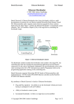
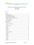
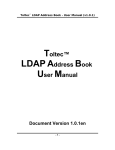
Brush Electronics
Ethernet Bootloader Ver 1.1
User Manual
Ethernet Bootloader
© 2003-2006 Andrew Smallridge
[email protected]
www.brushelectronics.com
The Brush Electronics Ethernet Bootloaders have been developed to deliver a rapid
development environment for an Ethernet enabled Microchip Flash Memory based
PIC Microcontroller and to support remote firmware upgrade for these systems
deployed in the field. Figure 1 outlines the Ethernet Bootloader’s conceptional system
elements. The LAN Interface Adapter (LIA) is the target device containing the
bootloader image.
Programmer
Application
Operating System
Socket API
UDP
Packets
NIC
Ethernet
LIA
IP Network
Controlling Host
Bootloader
Figure 1: Ethernet Bootloader System
The Bootloader solution includes the bootloader code resident in the target PIC, the
controlling host (the host running the programming application) and an Ethernet
connection. For the sake of subsequent explanation, the term Bootloader refers to the
code executing in the LIA’s PIC microprocessor and the Programmer refers to the
programming application running on the controlling host.
The Brush Electronics Ethernet Bootloader supports Microchips PIC18F family of
Microcontrollers with implementations s the Microchip ENC28J60 Ethernet controller
and the RealTek RTL8019AS Ethernet controller.
Key attributes of Brush Electronic’s family of Ethernet Bootloaders:
•
Plug and Play operation – the ability to use the bootloader without previously
having to configured it with an IP address
•
Ability to bootload a remote system
•
Incremental bootloader. As little as a single byte can be modified
© Copyright 2004-2006 Andrew Smallridge
Page 1 of 13
Brush Electronics
Ethernet Bootloader Ver 1.1
User Manual
•
No resources are required on the target PIC other than the flash memory
holding the boot code
•
Transparent to the user’s code. The bootloader is located in high program
memory and automatically intercepts the application programs reset vectors.
•
Report status to the programming application used for implementing a
“reliable service”
•
Uses standard Intel Hex Files
•
Is capable of uploading and downloading program and EEPROM data
Plug and Play operation over Ethernet is achieved via the use of multicast IP
operation enabling the dynamic discovery and operation of a LIA on a local network
segment. No “gleaming” is required to talk to the Bootloader. Remote support is
achieved via Unicast IP operation enabling a LIA on the other side of the world to be
remotely programmed. Flexible operating modes, embedded diagnostics and reliable
service challenge the third requirement, the need to minimise the memory footprint of
the loader to maximise the available user code space.
Bootloader Memory MAP
The Bootloader code resides in the upper portion of the program memory space.
Because this program memory is flash memory based, user configurable optional
parameters are also stored in this space. The EEPROM memory space internal to the
PIC is preserved unchanged by the Bootloader. The Bootloader transparently uses the
PIC’s reset vector, that is, the lower 8 bytes of program memory. The user’s reset
vector is transparently mapped into an 8 byte block within the Bootloader’s code
space. The user’s code MUST implement a GOTO instruction (a long jump) in the
first 4 instructions. The Bootloader code includes a RESET instruction immediately
following the remapped vector block. If the user’s program fails to implement a
GOTO instruction in the first 4 instructions, then the RESET instruction is executed.
The following diagram shows s typical bootloader’s memory MAP. The actual
address ranges in use will depend on the program memory space size of the specific
PIC.
© Copyright 2004-2006 Andrew Smallridge
Page 2 of 13
Brush Electronics
Ethernet Bootloader Ver 1.1
User Manual
LDR Reset Vector
Program
Memory
User Memory Space
0x0008
0x7000
Bootloader
Program
0x7FFF
MEMORY MAP
Basic Operation
The Bootloader code in the PIC and PC based programmer application use flags to
control the boot load process. Two of these flags determine the boot up behaviour of
the PIC:
•
•
The PENDING RESET VECTOR is used to indicate that the user’s RESET
vector has not yet been received.
The INVALID USER CODE SPACE flag indicates that an Intel End-of-File
hex record has not yet been received.
The LIA’s Bootloader code is executed automatically as a result of a power on reset, a
reset command or a jump to absolute address 0000h. The Bootloader is now in
BOOTLOADER DISCOVERY MODE. If either of the two critical flags is set the
programmer will automatically enter LOADER COMMAND MODE. This generally
indicates the user code space is empty or has previously been invalidated.
If neither of the critical flags has been set, the loader will wait for five seconds
looking for a command from the Programmer via the Ethernet interface to put the LIA
into LOADER COMMAND MODE. If no command is received the Bootloader
passes control to the user’s application code via the remapped reset vector. Note that
the Bootloader and the user’s code do not operate concurrently – this explains why the
loader does not require any of the PICs resources other than the consumed program
memory.
The Bootloader accepts commands from the Programmer using multicast and / or
unicast IP packets. UDP (User Datagram Protocol) is used between the Bootloader
and the programmer. The IP datagram service provides a good fit for exchanging Intel
Hex File records (lines in the hex file) however UDP is an unreliable service which
© Copyright 2004-2006 Andrew Smallridge
Page 3 of 13
Brush Electronics
Ethernet Bootloader Ver 1.1
User Manual
means that the application (both the Bootloader and the programmer) must implement
their own error detection, reporting and, where applicable, retransmission.
The Bootloader implements an incremental programming mechanism. This means
that it will program only the bytes specifically contained in the record to be
programmed. Code changes down to a single byte granularity are supported and the
remaining program memory space contents are preserved.
Using the programming application
The following diagram is a screenshot of the LIA Loader Utility. The LIA’s
Bootloader has been captured and the hex file HEAD.ASM has been programmed
into the LIA via the Bootloader. The Status information is displayed in the right hand
memo pane. Note the LIA_ID in the Configure LIA drop down menu box. This
selects the target Bootloader (which LIA is to be programmed).
The LIA Response memo pane will usually be empty. This pane is used to display
error messages. The bootloader will use either multicast or unicast IP depending on
the settings contained in the configuration INI file located in the same directory as the
programming application.
There are two alternatives for downloading code to a LIA (target system). The manual
method is used to identify the specific LIA to be programmed. The automatic method
is used to perform automatic discovery. If there are multiple LIA devices in
bootloader mode on the network then the first method would be used, otherwise the
latter is a more user friendly method.
Automatic Method - steps for downloading code to a LIA via the Bootloader and
Programmer Application:
Step 1 – Click “Capture Target” to initiate device discovery and capture. If the
“Configure LIA” drop down box is empty, the Capture Target button will
© Copyright 2004-2006 Andrew Smallridge
Page 4 of 13
Brush Electronics
Ethernet Bootloader Ver 1.1
User Manual
initiate a LIA discovery packet and start a retry timer. If the drop down box is
not empty than a LOADER COMMAND MODE command packet will be
sent to the LIA matching the ID in the drop down box. This process will repeat
every 500ms (retry interval) until the LIA responds to the command or until
the “Stop Capture” button is operated. Once a LIA has responded to the
discovery packet, its ID will be added to the “Configure LIA” drop down box
and, as a result, the next time the retry timer expires a LOADER COMMAND
MODE command packet will be sent to the LIA.
Step 2 – Power cycle or reset the target device to be programmed. This will
put the Bootloader into BOOTLOADER DISCOVERY MODE and enable the
Bootloader to respond to discovery packets from the programming application.
As a result of the “Capture Target” sequence initialised in step 1, the LIA
should respond and be captured within seconds. Once captured, the target
device remains in LOADER COMMAND MODE. In this mode the flash and
EEPROM memory of the target device can be read, erased and programmed.
Step 3 – Select the desired read, erase or program operation. Note that to
program the Bootloader from a hex file, you must first select the source file
using the “File” button. The identified file and path will be displayed in the
file window. The hex file is opened when the Program button is clicked and
close at completion of the programming cycle. The next time the Program
button is clicked the source file is again opened. This is important because it
means that the Bootloader is always being programmed with the current
contents of the source file. The edit control Record to Program can be used for
sending individual records to the Bootloader. The Overwrite LIA button is
used to invalidate the user’s program memory space without erasing the user’s
program. A LIA in this mode will stay in BOOTLOADER DISCOVERY
MODE after being reset without passing control to the user’s program.
Step 4 – Once the LIA has been successfully programmed or read, click the
Reset LIA button which will issue a LOADER RESET COMMAND to the
Bootloader.
Manual Method - steps for downloading code to a LIA via the Bootloader and
Programmer Application:
Step 1 – Power cycle or reset the target device to be programmed. This will
put the Bootloader into BOOTLOADER DISCOVERY MODE and enable the
Bootloader to respond to discovery packets from the programming application.
Step 2 – Click “Locate LIA” to initiate device discovery to find all devices
currently in BOOTLOADER DISCOVERY MODE. The first device to be
discovery will have it’s LIA_ID displayed in the Configure LIA drop down
control. If multiple devices were discovered then the target device can be
selected in the Configure LIA drop down box.
Step 3 – Within 5 seconds of Step 1, click the “Capture Target” button. This
will send the LOADER COMMAND MODE command to the LIA, identified
© Copyright 2004-2006 Andrew Smallridge
Page 5 of 13
Brush Electronics
Ethernet Bootloader Ver 1.1
User Manual
in the Configure LIA control, to Capture the Bootloader. Once captured, the
target device remains in LOADER COMMAND MODE. In this mode the
flash and EEPROM memory of the target device can be read, erased and
programmed.
Step 4 – Select the desired read, erase or program operation. Note that to
program the Bootloader from a hex file, you must first select the source file
using the “File” button. The identified file and path will be displayed in the
file window. The hex file is opened when the Program button is clicked and
close at completion of the programming cycle. The next time the Program
button is clicked the source file is again opened. This is important because it
means that the Bootloader is always being programmed with the current
contents of the source file. The edit control Record to Program can be used for
sending individual records to the Bootloader. The Overwrite LIA button is
used to invalidate the user’s program memory space without erasing the user’s
program. A LIA in this mode will stay in BOOTLOADER DISCOVERY
MODE after being reset without passing control to the user’s program.
Step 5 – Once the LIA has been successfully programmed or read, click the
Reset LIA button which will issue a LOADER RESET COMMAND to the
Bootloader.
When the LOADER RESET COMMAND is executed the LIA executes the
Bootloader code and waits for 5 seconds to receive the LOADER COMMAND
MODE command. If this command is not received and the critical flags are clear then
the loader passes control to the user’s application program.
Programmer Application - Under the Hood
The Programmer Application is written in Delphi for the windows environment. The
application should compile unchanged with Kylix for Linux but I have not tested this.
The application uses the freeware INDY control TIdUDPClient for reading and
writing packets to the network. The Indy software is licensed under the Indy Modified
BSD License which is included in the files for this project. The Indy package is
installed as standard in Delphi Enterprise addition 6 and 7. Indy versions 8 and 9 are
compatible with this application. For Personal Delphi or Delphi 2005 you will need to
download install one of these compatible versions from http://www.nevrona.com/indy
The Programmer and Bootloader are implemented in a client / server arrangement.
The Programmer (client) issues commands to the Bootloader (server) which executes
the commands and returns status information for each command. The Programmer
application is multithreaded, implementing a read thread for processing packets
received from the Bootloader. Packets sent to the Bootloader are handled by the main
thread. The Programmer Application uses a timer control as part of the error detection
and processing mechanism for the READ, ERASE and PROGRAM commands.
© Copyright 2004-2006 Andrew Smallridge
Page 6 of 13
Brush Electronics
Ethernet Bootloader Ver 1.1
User Manual
In the event that no status is returned for the current record, the timer will expire and a
consecutive error counter variable will be incremented. If this is CEC value below the
maximum consecutive error threshold then the timer is restarted and the previously
saved current record is retransmitted.
LIA Bootloader - Under the Hood
The following diagram is a simplified representation of the Bootloader code operation:
© Copyright 2004-2006 Andrew Smallridge
Page 7 of 13
Brush Electronics
Ethernet Bootloader Ver 1.1
User Manual
Packet Formats
Packets sent from the bootloader to the programmer can be sent to the Unicast
Address of the Bootloader or the Multicast Address. IP packets can be Unicast for
point to point communications, Broadcast to all devices on a subnet, or Multicast to a
targeted subset of devices. Devices interested in receiving multicast packets will
configure the network interfaces to accept specific multicast MAC layer addresses.
These MAC layer addresses map to corresponding IP multicast addresses. The
Bootloader configures the Ethernet Controller chip with a multicast filter mask in
order to accept multicast packets destined for the multicast address 230.10.10.11
Unicast packets sent by the Application Programmer will have the TTL (Time-to-Live)
field set to 255. Network routers along the path between the Source and Destination
decrement this value by 1. If as a result of decrementing the TTL field, the result is
zero, then instead of forwarding the packet out of the destination interface the router
will discard the packet. This is the mechanism IP networks use to prevent packets
looping for ever in the network. For Unicast packets this means the packet can
traverse up to 254 routers.
For Multicast packets, the Programmer Application sets the TTL field to 1. The first
time a router tries to forward the packet, the TTL field is decremented to zero and the
router discards the packet. This mechanism limits Bootloader multicast packets to the
local IP network segment. Multicast therefore provides us a mechanism to support
plug and play operation. We do not need to assign an IP address to the Bootloader to
be able to communicate with it over an IP network and we use the TTL limited to
limit the traffic to the local segment. The multicast mechanism allows us to operate
multiple bootloaders on the same network segment. This is accomplished using the
LIA_ID which is derived from the MAC address of the Bootloader.
Programmer to LIA Communications
Network Headers
Ethernet
IP
Programmer Command
UDP Command Header
Header (7 Bytes)
Data
CRC
Command Payload (0 to 43 bytes)
The Network Header portion is a convention UDP packet structure. The destination IP
address is either the Unicast IP Address of the LIA or the Multicast IP address
230.10.10.11 The destination UDP port number for the Bootloader is 0x4000.
© Copyright 2004-2006 Andrew Smallridge
Page 8 of 13
Brush Electronics
Ethernet Bootloader Ver 1.1
User Manual
The Programmer Command is carried in the data portion of the UDP packet. This
comprises a 7 byte command header and an optional variable length payload.
PROGRAMMER PAYLOAD STRUCTURE
Field
Length
Description
*************************************************************
LIA_TAG
2 bytes
5AA5
LIA_ID
2 bytes
Unique 2 byte LIA identifier
Sequence
2 bytes
Incremental Sequence Number
Command
1 byte
Command Payload
0 to 36 bytes
LIA_TAG: a fixed pattern used to protect against the remote possibility that another
device on the network is using the same IP address and port number. If the Key field
of the incoming packet does not match then the record is discarded. The bootloader
also checks to ensure all command structures are valid.
LIA_ID: the last two byes of the Bootloader’s MAC address. The Bootloader
generates a pseudo unique MAC address the very first time it is powered up. This
MAC address is subsequently stored in the Bootloader’s program memory space.
Subsequent powering up of the LIA will use the MAC address stored in the
Bootloader’s program memory space. This LIA ID mechanism enables multiple LIAs
to share a common network segment and still enable each LIA to be uniquely
programmed by the Programmer application. All Bootloaders will respond to a status
request if the target LIA_ID field is set to 0000. When the Bootloader responds it puts
it’s LIA_ID into the corresponding field. This is the mechanism used by the
Programmer Application to discover all Bootloaders on the network segment. Other
than the Status Command, the Bootloader will ignore all commands that do not
specifically match the Bootloader’s LIA_ID
Sequence: This field is incremented by the Programmer application. It is used by the
Bootloader to detect lost command packets. Sequence numbers and acknowledgement
timers are used to detect and recover from lost packets.
Command: Command issued by the Programming Application to the Bootloader.
The commands are discussed later in this section.
Payload: Two commands use the optional payload field, the
Set_IP address command contains a four byte IP address to be assigned to the
Bootloader. This IP address is stored in the Bootloader Program Memory space and
permanently overwrites the default IP address.
New_Code: This contains an Intel INHX32 record – that is, a line from the hex file
produced by an assembler and will be a type 0, type 1, or type 4 record.
The following diagram shows the Programmer Payload structure for packets send
from the programmer to the Bootloader. Each command comprises of a seven byte
command header.
The following figure gives a breakdown of the ten commands supported by the
bootloader and the length of the optional payload field.
© Copyright 2004-2006 Andrew Smallridge
Page 9 of 13
Brush Electronics
Ethernet Bootloader Ver 1.1
User Manual
COMMAND FORMAT – Programmer to Bootloader
Command
Value Payload Comment
*************************************************************
CP_Status
0
0
Show status
CP_SetIP
1
4
Set IP address
CP_Invalidate
2
0
Invalidate User Program Area
CP_LDR_Mode
3
0
Put LIA into Loader State
CP_New_Code
4
7 - 36
New code to store
CP_Dump
5
0
Dump user memory and EEPROM
CP_Erase
6
0
Erase Program Memory and EEPROM
CP_Erase_PGM
7
0
Erase Program Memory only
CP_Erase_EE
8
0
Erase EEPROM only
CP_Reset
9
0
Reboot the LIA
Most commands are self explanatory and further information can be found in the
source code for the Programmer Application. The Invalidate command sets a flag in
the Bootloader code which prevents the bootloader from passing control to the user’s
program. Effectively the user’s program space has been invalidated but it has not been
erased. It is possible to reverse the Invalidate status by sending a single type 1 (endof-file) record to the Bootloader with the New_Code command.
The LDR_Mode command (Loader Mode) captures the Bootloader to prevent the
Bootloader passing control to the user’s application program at the end of the initial 5
second period from reset. In this mode the Bootloader is under the control of the
Programmer application. The user’s code is not invalidated – if the LIA is reset while
in this mode then after 5 seconds control will once again be passed to the user’s
program provided the user’s code space is valid.
The Dump command will upload the contents of the User’s program memory and
EEPROM memory space to the Programmer Application. The Bootloader uses the
same INHX32 Intel Hex record format.
All commands will result in a status packet being sent to the Programmer Application
indicating the success or otherwise of the command. Lack of status information is
interpreted by the programmer as a lost or missing command acknowledgement and
will result in the application programming reissuing the previous command. In the
worst case scenario this means the bootloader may program the same record (line of
the Hex file) twice.
© Copyright 2004-2006 Andrew Smallridge
Page 10 of 13
Brush Electronics
Ethernet Bootloader Ver 1.1
User Manual
Bootloader to Programmer Communications
Network Headers
Ethernet
IP
UDP
Bootloader Status
Status Header
Header (19 Bytes)
Data
CRC
Dump Record (0 to 41 bytes)
BOOTLOADER STATUS STRUCTURE
Field
Length
Description
*************************************************************
LIA_TAG
2 bytes
5AA5
Target_ID
2
0x0000
Sequence
2 bytes
Command sequence number
Command
1
LIA command byte
Product_ID
1
LIA product identifier - 0x01
HW_version
1
Major / Minor 4 bits each
SW_Version
1
Major / Minor 4 bits each
LIA_ID
2 bytes
Unique 2 byte LIA identifier
IP_addr
4
User configurable IP address
LIA_State
2
LIA status Word
Data_Seq
1
Next Data Sequence Number to
be used for data traffic
INHX32 record
0..41
Variable command payload
The status record reflects the command status header information to the Programmer
Application as well as some additional fields. The Data sequence number is used for
lost packet detection for the dump command. The Application program currently uses
this information to report error status and terminate the dump command but it does
not automatically issue another dump command.
Structure of Intel HEX file records
:AABBBBCCDDDD..EE
Where
:
AA
BBBB
CC
DD..
EE
indicates the start of the current record
number of data bytes in the record
target address of the first byte in this record.
record Type
00 Data Record
01 End of File Record
04 Linear Address Record
data
checksum calculated across the record. Excludes the : character
© Copyright 2004-2006 Andrew Smallridge
Page 11 of 13
Brush Electronics
Ethernet Bootloader Ver 1.1
User Manual
Extract from INHX32 (Intel 32 bit hex file) produced by Microchip MPASM.
This figure show the use of type 4 records in the hex file which identifies the target
memory page used by the bootloader to determine the target for subsequent data (type
0) records. The Bootloader ignores data records targeted to the configuration bits. The
first record of the file is a type 4 record identifying the target for subsequent data
records in the Program Memory Space until the receipt of a subsequent type 4 record
or an EOF record.
Record Type
Program Memory Space
:020000040000FA
:0400000080EF00F09D
:0400080080EF00F095
:10010000F29E0A0E86EC00F000EF00F0036EE80E9F
..
Configuration Bits Memory Space
:020000040030CA
:0E000000FFFAFEFEFFFFFBFFFFFFFFFFFFFF0B
EEPROM Memory Space
:0200000400F00A
:100000003030204550524F4D204461746120737050
..
End of File
:00000001FF
Unicast – directed traffic between two devices
Broadcast – flooding from a device to all other devices in a common broadcast
domains - typically to all devices in a subnet
Multicast – Subset of broadcast, packets are sent to a common community. IP
224.0.0.0 to 239.255.255.255 CLASS D
This address range is only for the group address or destination address of IP multicast
traffic. The source address for multicast datagrams is always the unicast source
address. RFC1112
Limitations of the Bootloader
The following limitations of the Bootloader must be taken into account:
• The LIA registers are not preserved by a RESET
• No support for WDT fuse bit. WDT support if required must be implemented
by the software enabled WDT feature
• User’s program must execute a GOTO instruction within the first four
instructions
• The Bootloader ignores Configuration Records and ID records
Final Thoughts
The Ethernet Bootloader is a great tool for developing those “wouldn’t it be great to
reach this over the network” projects. Developing Ethernet enabled Microcontroller
projects is much easier today than when I started with the LIA. Microchip offers a
© Copyright 2004-2006 Andrew Smallridge
Page 12 of 13
Brush Electronics
Ethernet Bootloader Ver 1.1
User Manual
free IP stack for use with Microchip PICs and they have a number of good proof of
concept kits with the PICDEM.NET and the ENC28J60 Ethernet PigTail board. The
LIA Bootloader does not use any of the Microchip stack, this is because the
Bootloader is optimised for space, while the stack is optimised for performance. For
this reason I did not open any of the Bootloader APIs for use by target applications.
Brush Electronics
2 Brush Court
Canning Vale
Western Australia 6155
Australia
Tel: +61 (0) 894557024
Email: [email protected]
www: www.brushelectronics.com
© Copyright 2004-2006 Andrew Smallridge
Page 13 of 13