1
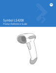
Brush Electronics
Generic Serial Bootloader System
Version 1.1 – 7th January, 2010
User Manual
Generic Serial Bootloader System
© 2003-2010 Andrew Smallridge
[email protected]
www.brushelectronics.com
Brush Electronics’ Generic Serial Bootloaders have been developed to support remote
firmware upgrade for the Microchip PIC base Micrcontroller systems deployed in the
field.
The Brush Electronics’ Serial Bootloader System comprises of two main elements:
1. Bootloader Firmware resident in the target hardware platform
2. Programmer application executing on the controlling host
For the sake of subsequent explanation, the term Bootloader refers to the code
(firmware) executing in the PIC microprocessor (target), the Programmer refers to the
programming application running on the controlling host computer.
The Brush Electronics’ Generic Serial Bootloader is available for the Microchip
PIC18F family of Microcontrollers.
Key attributes of Brush Electronics’ Generic Serial Bootloaders:
•
Ability to bootload a remote system
•
Incremental Bootloader. As little as a single byte can be modified
•
No resources are required on the target PIC other than the flash memory
holding the boot code
•
The PIC18F version Generic Serial Bootloader is located in high program
memory
•
Bootloads standard Intel Hex Files
•
Dumps program memory contents to the bootloader application
Bootloader Memory MAP
The Bootloader code resides in a portion of the program memory space. Because this
program memory is flash memory based, user configurable optional parameters are
also stored in this space. The Bootloader transparently uses the PIC’s reset vector, that
is, the lower 8 bytes of program memory. The user’s reset vector is transparently
mapped into a program memory block in the Bootloader’s code space into the region
referred to as the Bootloader parameter block. The location of the bootloader
parameter block is defined in the file ldr-serial.INC
© Copyright 2004-2010 Andrew Smallridge
Page 1 of 6
Brush Electronics
Generic Serial Bootloader System
Version 1.1 – 7th January, 2010
User Manual
The user’s code MUST implement a GOTO instruction (a long jump) in the first 4
instructions. Typically this GOTO instruction is automatically inserted during the
linking stage. The Microchip C18 compilers, when used with their respective standard
linker scripts, automatically insert the GOTO instruction.
Basic Operation
The Bootloader code in the PIC and PC based programmer application use flags to
control the boot load process. Two of these flags determine the boot up behaviour of
the PIC:
•
•
The PENDING RESET VECTOR is used to indicate that the user’s RESET
vector has not yet been received.
The INVALID USER CODE SPACE flag indicates that an Intel End-of-File
hex record has not yet been received.
The PIC’s Bootloader code is executed automatically as a result of a power on reset, a
reset command or a jump to absolute address 0x0000. Wherever possible a CPU reset
should be used to enter the Bootloader as this forces all registers associated with
interrupts to a known state. The Bootloader is now in BOOTLOADER DISCOVERY
MODE. If either of the two critical flags is set the programmer will automatically
enter LOADER COMMAND MODE. This generally indicates the user code space is
empty.
If neither of the critical flags has been set, the loader will wait for five seconds
looking for a command from the Programmer via the serial interface to put the
Bootloader into LOADER COMMAND MODE. If no command is received the
Bootloader passes control to the user’s application code via the remapped reset vector.
Note that the Bootloader and the user’s code do not operate concurrently – this
explains why the loader does not require any of the PICs resources other than the
consumed program memory.
The Bootloader accepts commands from the Programmer via a serial interface. Serial
communications, especially in noisy environments or as a result of long
communications paths, can be unreliable resulting in lost or corrupted characters
therefore the programmer application, in conjunction with the Bootloader firmware,
implements error detection, reporting and, where applicable, retransmission.
The Bootloader implements an incremental programming mechanism. This means
that it will program only the bytes specifically contained in the record to be
programmed. Code changes down to a single byte granularity are supported and the
remaining program memory space contents are preserved.
Using the programming application
The user interface of the Generic Serial Bootloader is very similar to the user interface
of our Encrypted Serial Bootloader Utility. The following image is a screenshot of the
Encrypted Serial Bootloader Utility. The Target’s Bootloader has been captured and
the encrypted hex file demo.cry has been selected for programming into the target via
© Copyright 2004-2010 Andrew Smallridge
Page 2 of 6
Brush Electronics
Generic Serial Bootloader System
Version 1.1 – 7th January, 2010
User Manual
the Encrypted Serial Bootloader. In the case of the Generic Serial Bootloader,
standard Intel Hex format files are downloaded to the PIC.
The Program Status information is displayed in the right hand side memo pane. The
Target Response memo pane shows the time the last message was received from the
Bootloader as a response to control and data messages from the Serial Bootloader
Utility.
© Copyright 2004-2010 Andrew Smallridge
Page 3 of 6
Brush Electronics
Generic Serial Bootloader System
Version 1.1 – 7th January, 2010
User Manual
Steps for downloading code to a target via the Bootloader and Programmer
Application:
Step 1 – Reset the Target system.
Step 2 – Within 3 seconds of Step 1, Click Capture Target to initiate device
discovery and capture. The programmer application will send a capture
message to the Bootloader and wait for an acknowledgement from the
Bootloader indicating it has been capatured. This sending of the capture
message will repeat every 500ms (retry interval) until the Bootloader responds
to the command or until the Stop Capture button is operated.
Step 3 – Select the desired erase or program operation. Note that to program
the Bootloader from a file, you must first select the source file using the File
button. The source files have the extension “.hex”. The identified file and path
will be displayed in the file window. The source file is opened when the
Program button is clicked and closed at completion of the programming cycle.
The next time the Program button is clicked the source file is again opened.
This is important because it means that the Bootloader is always being
programmed with the current contents of the source file.
Step 4 – Once the target has been successfully programmed, click the Reset
Target button which will issue a LOADER RESET COMMAND to the
Bootloader.
When the LOADER RESET COMMAND is executed the target executes the
Bootloader code and waits for approximately 5 seconds to receive the capture
command. If this command is not received and the critical flags are clear then the
loader passes control to the user’s application program.
Programmer Application
The commands available via the Programmer’s GUI interface are self explanatory and
further information can be found in the source code for the Programmer Application.
The Capture Target command (Loader Mode) captures the Bootloader to prevent the
Bootloader passing control to the user’s application program at the end of the initial 5
second period from reset. In this mode the Bootloader is under the control of the
Programmer application. If he user’s code space is valid and the target is reset while
in this mode then after 5 seconds control will once again be passed to the user’s
program.
The Programmer and Bootloader are implemented in a client / server arrangement.
The Programmer (client) issues commands to the Bootloader (server) which executes
the commands and returns status information for each command. The Programmer
application is multithreaded, implementing a read thread for processing packets
received from the Bootloader. Packets sent to the Bootloader are handled by the main
thread. The Programmer Application uses a timer control as part of the error detection
and processing mechanism for the various ERASE and PROGRAM commands.
© Copyright 2004-2010 Andrew Smallridge
Page 4 of 6
Brush Electronics
Generic Serial Bootloader System
Version 1.1 – 7th January, 2010
User Manual
All commands from the Programmer application to the Bootloader will result in a
status packet being sent from the Bootloader to the Programmer Application
indicating the success or otherwise of the command. In the event that no status is
returned by the Bootloader for the current record, the timer will expire and a
consecutive error counter variable will be incremented. If this is consecutive error
counter value below the maximum consecutive error threshold then the timer is
restarted and the previously saved current record is retransmitted.
The Programmer Application is written in Delphi for the windows environment. The
application uses the freeware Ararat Synapse SynaSer serial library. The serial library
can be downloaded from http://synapse.ararat.cz/doku.php/download
Customization
The bootloader must be customized to support different hardware plaforms (targets)
and microcontrollers. IN general the customizationrequired the following steps:
•
•
•
•
•
Define target hardware platform in the platform.h file
In the Microchip IDE, select the processor in the the menu Configure / Select
Device
Create the processor specific bootloader linker script for compiling the
bootloader. Refer to the sample bootloader linker scripts supplied with the
bootloader package which contains instructions for modifying a standard
linker script
Create the processor specific bootloader linker script for compiling the user
application to coreside with the bootloader. Refer to the sample application
linker scripts supplied with the bootloader package which contains instructions
for modifying a standard linker script
Modify the bootloader’s main source file to specify the target specific fuses
© Copyright 2004-2010 Andrew Smallridge
Page 5 of 6
Brush Electronics
Generic Serial Bootloader System
Version 1.1 – 7th January, 2010
User Manual
Limitations of the Bootloader
The following limitations of the Bootloader must be taken into account:
• The target’s registers are not preserved by a RESET
• No support for WDT fuse bit. WDT support if required must be implemented
by the software enabled WDT feature
• User’s program must execute a GOTO instruction within the first four
instructions
• The Bootloader ignores Configuration Records and ID records
Need Something Special?
What if you need some unique feature added to the Bootloader or a Bootloader
developed for some other product? Brush Electronics specializes in the development
of Bootloaders for Microchip Microcontrollers and welcome the opportunity to work
with you to develop a custom product that meets your specific needs.
Brush Electronics
2 Brush Court
Canning Vale
Western Australia 6155
Australia
Tel: +61 (0) 894676358
Email: [email protected]
www: www.brushelectronics.com
© Copyright 2004-2010 Andrew Smallridge
Page 6 of 6