1
MITSUBISHI ELECTRIC
MELSEC System Q
Programmable Logic Controllers
User's Manual
QJ61BT11N
CC-Link Master/Lokal Module
Art. no.: 158161
01 07 2005
SH (NA)-080394E
Version D
MITSUBISHI ELECTRIC
INDUSTRIAL AUTOMATION
• SAFETY PRECAUTIONS •
(Always read these precautions before using this equipment.)
Before using this product, please read this manual and the relevant manuals introduced in this manual
carefully and pay full attention to safety to handle the product correctly.
The precautions given in this manual are concerned with this product. For the safety precautions of the
programmable controller system, please read the user's manual of the CPU module to use.
In this manual, the safety precautions are ranked as "DANGER" and "CAUTION".
DANGER
Indicates that incorrect handling may cause hazardous conditions,
resulting in death or severe injury.
! CAUTION
Indicates that incorrect handling may cause hazardous conditions,
resulting in medium or slight personal injury or physical damage.
!
Note that the ! CAUTION level may lead to a serious consequence according to the circumstances.
Always follow the precautions of both levels because they are important to personal safety.
Please save this manual to make it accessible when required and always forward it to the end user.
[DESIGN PRECAUTION]
!
DANGER
• See Chapter 5 of this manual for each station's operating status when there is a communication
error in the data link.
• When performing the control of the PLC in operation (changing data) by connecting a personal
computer, etc. to the intelligent function module or connecting peripheral devices to the CPU
module, configure an interlock circuit in a sequence program so the safety of the overall system
is always maintained.
Before performing other controls of the PLC in operation (changing program and operation
status (status control)), read this manual carefully and confirm if the overall safety is maintained.
Especially, when this control is performed to a remote PC from an external device, troubles that
have occurred on the PLC side may not be able to immediately be handled if there is a data
communication error.
Define a troubleshooting agreement between external devices and the PLC CPU for data
communication error occurrences, as well as construct an interlock circuit in the sequence
program.
A-1
A-1
[DESIGN PRECAUTION]
!
DANGER
• Do not write data into the "system area" of the buffer memory of intelligent function modules.
Also, do not output the "prohibited to use" signal as the output signal to an intelligent function
module from the PLC CPU.
Writing data into the "system area" or outputting a signal for "prohibited to use" may cause
system malfunction in the PLC.
• To specify the automatic refresh parameter, specify "Y" for the remote output RY refresh device.
If a value other than "Y" (for example, M or L) is specified, the status of the device will remain as
it was prior to the STOP operation when the CPU is stopped.
See Section 4.4.10 for how to stop the data link.
• If wire breakage occurs in the CC-Link dedicated cable, the line may become instable, resulting
in a data link communication error at multiple stations. Configure an interlock circuit in a
sequence program to operate the system toward the safety side if a data link communication
error occurs at multiple stations. Failure to do so may result in an accident due to false output or
malfunction.
[DESIGN PRECAUTION]
!
CAUTION
• Do not bunch the control wires or communication cables with the main circuit or power wires, or
install them close to each other.
They should be installed 100mm(3.9inch) or more from each other.
Not doing so could result in noise that may cause malfunction.
[INSTALLATION PRECAUTIONS]
!
CAUTION
• Use the PLC in an environment that meets the general specifications contained in the CPU
user's manual to use.
Using this PLC in an environment outside the range of the general specifications may cause
electric shock, fire, malfunction, and damage to or deterioration of the product.
• While pressing the installation lever located at the bottom of module, insert the module fixing tab
into the fixing hole in the base unit until it stops. Then, securely mount the module with the fixing
hole as a supporting point.
Improper installation may result in malfunction, breakdown or dropping out of the module.
Securely fix the module with screws if it is subject to vibration during use.
• Tighten the screws within the range of specified torque.
If the screws are loose, it may cause fallout, short circuits, or malfunction.
If the screws are tightened too much, it may cause damage to the screw and/or the module,
resulting in fallout, short circuits or malfunction.
• Be sure to shut off all phases of the external power supply used by the system before mounting
or removing the module.
Not doing so may cause damage to the module.
• Do not directly touch the conductive area or electronic components of the module.
Doing so may cause malfunction or failure in the module.
A-2
A-2
[WIRING PRECAUTIONS]
!
CAUTION
• When turning on the power and operating the module after installing is completed, always attach
the terminal cover that comes with the product.
There is a risk of malfunction if the terminal cover is not attached.
• Tighten the terminal screws within the range of specified torque.
If the terminal screws are loose, it may cause short circuits, or malfunction.
If the terminal screws are tightened too much, it may cause damage to the screw and/or the
module, resulting in fallout, short circuits or malfunction.
• Be careful not to let foreign matters such as sawdust or wire chips get inside the module.
These may cause fires, failure or malfunction.
• The top surface of the module is covered with protective film to prevent foreign objects such as
cable offcuts from entering the module when wiring.
Do not remove this film until the wiring is complete.
Before operating the system, be sure to remove the film to provide adequate heat ventilation.
• Use a dedicated cable as specified by the manufacturer for the CC-Link system. If a cable other
than the one specified by the manufacturer is used, the performance of the CC-Link system
cannot be guaranteed. Also, follow the specifications listed in Chapter 3 for the overall cable
distance and the station-to-station cable length. If wiring is done other than as specified,
accurate transmission of data cannot be guaranteed.
• Be sure to fix communication cables or power supply cables leading from the module by placing
them in the duct or clamping them.
Cables not placed in the duct or without clamping may hang or shift, allowing them to be
accidentally pulled, which may cause a module malfunction and cable damage.
• Do not install the control lines together with the communication cables, or bring them close to
each other. Failure to do so may cause malfunctions due to noise.
• Be sure to fix the wires or cables by ducts or clamps when connecting them to the module.
When removing the cable with a connector, hold the connector on the side that is connected to
the module.
When removing the cable connected to the terminal block, first loosen the screws on the part
that is connected to the terminal block.
Pulling the cable that is still connected to the module may cause malfunction or damage to the
module or cable.
A-3
A-3
[STARTING AND MAINTENANCE PRECAUTIONS]
!
CAUTION
• Do not disassemble or modify each module.
Doing so could cause failure, malfunction, injury or fire.
• Be sure to shut off all phases of the external power supply used by the system before mounting
or removing the module.
Not doing so may cause failure or malfunction of the module.
• Do not touch the connector while the power is on.
Doing so may cause malfunction.
• Be sure to shut off all phases of the external power supply before cleaning or retightening the
terminal screws or module fixing screws.
Not doing so may cause failure or malfunction of the module.
If the screws are loose, it may cause fallout, short circuits, or malfunction.
If the screws are tightened too much, it may cause damages to the screws and/or the module,
resulting in fallout, short circuits or malfunction.
Do not mount/remove the module onto/from the base unit more than 50 times (IEC 61131-2compliant), after the first use of the product. Failure to do so may cause malfunction.
• Always make sure to touch the grounded metal to discharge the electricity charged in the body,
etc., before touching the module.
Failure to do so may cause a failure or malfunctions of the module.
[DISPOSAL PRECAUTIONS]
!
CAUTION
• When disposing of this product, treat it as industrial waste.
A-4
A-4
REVISIONS
The manual number is given on the bottom left of the back cover.
Print Date
May, 2003
May, 2004
Manual Number
Revision
SH (NA)-080394E-A First edition
SH (NA)-080394E-B Addition
Appendix 6
Partial correction
SAFETY PRECAUTIONS, Section 2.2.1, Section 2.2.3, Section 2.2.4,
Chapter 4, Section 4.1, Section 4.3.3, Section 4.4.14, Section 7.2.1,
Section 8.2.2, Section 8.3.1, Section 8.3.2, Section 8.4.1, Section 8.4.2,
Section 13.1, Section 13.3, Appendix 3
Dec., 2004 SH (NA)-080394E-C
Partial correction
SAFETY PRECAUTIONS, Chapter 1, Section 2.2.1, Section 3.1,
Section 4.4.1, Section 4.4.2, Section 4.4.3, Section 4.4.14,
Section 5.4.1, Section 7.3, Section 8.4.2, Section 13.3, Appendix 2,
Appendix 2.3, Appendix 2.4, Appendix 2.5, Appendix 2.6, Appendix 2.7
Jul., 2005
Addition
Section 11.1
SH (NA)-080394E-D
Partial correction
SAFETY PRECAUTIONS, Section 2.2.1, Section 2.2.2, Section 4.4.3,
Section 4.4.6, Section 6.2, Section 6.3.1, Section 6.3.2, Section 6.4.1,
Section 6.4.2, Section 6.5.1, Section 6.5.2, Section 8.4.1, Section 8.4.2,
Section 9.1.2, Section 10.1.2, Section 10.2.2, Section 10.3.2,
Section 11.1.2, Section 11.2.3, Section 11.2.4, Section 11.2.5,
Section 11.3.2, Section 11.3.3, Section 11.3.4, Section 11.3.5,
Section 11.4.2, Section 11.4.3, Section 11.4.4, Section 11.4.5,
Section 13.3, Appendix 2.7, Appendix 7.1
Japanese Manual Version SH-080395-D
This manual confers no industrial property rights or any rights of any other kind, nor does it confer any patent
licenses. Mitsubishi Electric Corporation cannot be held responsible for any problems involving industrial property
rights which may occur as a result of using the contents noted in this manual.
2003 MITSUBISHI ELECTRIC CORPORATION
A-5
A-5
INTRODUCTION
Thank you for purchasing the MELSEC-Q series PLC.
Before using the equipment, please read this manual carefully to develop full familiarity with the functions
and performance of the Q series PLC you have purchased, so as to ensure correct use.
Please forward a copy of this manual to the end user.
CONTENTS
SAFETY PRECAUTIONS..............................................................................................................................A- 1
REVISIONS ....................................................................................................................................................A- 5
INTRODUCTION............................................................................................................................................A- 6
Conformation to the EMC Directive and Low Voltage Instruction ................................................................A-13
About the Generic Terms and Abbreviations ................................................................................................A-14
Product Components .....................................................................................................................................A-16
1 OVERVIEW
1- 1 to 1-12
1.1 Overview.................................................................................................................................................. 1- 1
1.2 Compatibility with CC-Link...................................................................................................................... 1- 2
1.3 Features .................................................................................................................................................. 1- 2
2 SYSTEM CONFIGURATION
2- 1 to 2- 9
2.1 System Configuration.............................................................................................................................. 22.2 Applicable System................................................................................................................................... 22.2.1 Applicable modules and number of CPUs that can be mounted.................................................... 22.2.2 Notes on the system configuration .................................................................................................. 22.2.3 How to check the function version................................................................................................... 22.2.4 CC-Link version................................................................................................................................ 23 SPECIFICATIONS
3- 1 to 3- 7
3.1 Performance Specifications .................................................................................................................... 33.1.1 Maximum overall cable distance (for Ver. 1.00).............................................................................. 33.1.2 Maximum overall cable distance (for Ver. 1.10).............................................................................. 33.2 CC-Link Dedicated Cable ....................................................................................................................... 34 FUNCTIONS
1
4
4
6
8
9
1
3
5
6
4- 1 to 4-75
4.1 Function List ............................................................................................................................................ 4- 1
4.2 Basic Functions ....................................................................................................................................... 4- 3
4.2.1 Communication with the remote I/O stations .................................................................................. 4- 3
4.2.2 Communication with the remote device stations............................................................................. 4- 5
4.2.3 Communication with the local stations ............................................................................................ 4-10
4.2.4 Communication with the intelligent device stations......................................................................... 4-16
4.2.5 Parameter setting with GX Developer ............................................................................................. 4-22
4.2.6 Parameter setting with dedicated instruction .................................................................................. 4-23
A-6
A-6
4.3 Functions for Improving System Reliability ............................................................................................ 4-25
4.3.1 Disconnecting data link faulty stations and continuing the data link with only normal stations
(Slave station cut-off function)......................................................................................................... 4-25
4.3.2 Automatically reconnecting a disconnected data link faulty station when it returns to normal
(Automatic return function) .............................................................................................................. 4-26
4.3.3 Continuing the data link when an error occurs in the master station PLC CPU
(Data link status setting when the master station PLC CPU has an error).................................... 4-27
4.3.4 Retaining the device status of a data link faulty station
(Setting the status of input data from a data link faulty station) ..................................................... 4-28
4.3.5 Clearing data in case of PLC CPU STOP
(Slave station refresh/compulsory clear setting in case of PLC CPU STOP) ............................... 4-29
4.3.6 Continuing the data link even when the master station is faulty
(Standby master function) ............................................................................................................... 4-31
4.4 Handy Functions ..................................................................................................................................... 4-45
4.4.1 Simplifying the initialization procedure registration of remote device stations
(Remote device station initialization procedure registration function) ........................................... 4-45
4.4.2 Performing high-speed processing (Event issuance for the interrupt program) ............................ 4-49
4.4.3 Enabling the data link simply by powering on (Automatic CC-Link startup) .................................. 4-52
4.4.4 Communicating with intelligent device stations (Remote net mode).............................................. 4-54
4.4.5 Speeding up the response from remote I/O stations (Remote I/O net mode) ............................... 4-54
4.4.6 Creating a program that contains modules to be added in the future
(Reserved station function) ............................................................................................................. 4-55
4.4.7 Powering off a station in operation without error detection
(Error invalid station setting function).............................................................................................. 4-56
4.4.8 Synchronizing the link scan with the sequence scan (Scan synchronous function)...................... 4-57
4.4.9 Replacing modules without error detection (Temporary error invalid station setting function) ..... 4-61
4.4.10 Checking operations for each local station (Data link stop/restart) .............................................. 4-62
4.4.11 Station number overlap checking function .................................................................................... 4-63
4.4.12 Multiple PLC system support ......................................................................................................... 4-64
4.4.13 Reducing the reserved points of the remote I/O stations (Remote I/O station points setting) .... 4-65
4.4.14 Increasing the number of cyclic points (Remote net ver.2 mode) ................................................ 4-67
4.5 Transient Transmission Functions ......................................................................................................... 4-75
4.5.1 Performing transient transmission (Dedicated instructions) ........................................................... 4-75
5 DATA LINK PROCESSING TIME
5- 1 to 5-45
5.1 Link Scan Time ....................................................................................................................................... 5- 1
5.2 Transmission Delay Time ....................................................................................................................... 5- 4
5.2.1 Master station
remote I/O station ............................................................................................... 5- 4
5.2.2 Master station
remote device station (Ver. 1 compatible slave station).................................... 5- 7
5.2.3 Master station
remote device station (Ver. 2 compatible slave station).................................... 5-12
5.2.4 Master station
local station (Ver. 1 compatible slave station) ................................................... 5-20
5.2.5 Master station
local station (Ver. 2 compatible slave station) ................................................... 5-26
intelligent device station ..................................................................................... 5-34
5.2.6 Master station
5.3 Processing Time for Dedicated Instructions .......................................................................................... 5-35
5.3.1 Master station
local station ......................................................................................................... 5-35
local station............................................................................................................ 5-38
5.3.2 Local station
5.3.3 Master station
intelligent device station ..................................................................................... 5-39
A-7
A-7
5.4 Link Refresh Time ................................................................................................................................... 5-40
5.4.1 Master station/local station .............................................................................................................. 5-40
5.5 Station Status at Error Occurrence ........................................................................................................ 5-44
5.5.1 Status of the master station, standby master station (when the master station is operating)
and remote I/O station at error occurrence..................................................................................... 5-44
5.5.2 Status of the remote device station, local station, standby master station
(when the local station is operating) and intelligent device station at error occurrence................ 5-45
6 PARAMETER SETTINGS
6- 1 to 6-52
6.1 Procedure from Parameter Settings to Data Link Startup ..................................................................... 6- 1
6.1.1 CPU parameter area and master module parameter memory....................................................... 6- 1
6.1.2 Procedure from parameter settings to data link startup with GX Developer.................................. 6- 2
6.1.3 Procedure from parameter settings to data link startup with dedicated instruction ....................... 6- 2
6.2 Parameter Setting Items ......................................................................................................................... 6- 3
6.3 Example of Parameter Settings with GX Developer (Remote net ver.1 mode).................................... 6- 5
6.3.1 Master station network parameter settings ..................................................................................... 6- 5
6.3.2 Master station automatic refresh parameter settings...................................................................... 6-10
6.3.3 Local station network parameter settings........................................................................................ 6-12
6.3.4 Local station automatic refresh parameter settings ........................................................................ 6-15
6.4 Example of Parameter Settings with GX Developer (Remote net ver.2 mode).................................... 6-17
6.4.1 Master station network parameter settings ..................................................................................... 6-17
6.4.2 Master station automatic refresh parameter settings...................................................................... 6-22
6.4.3 Local station network parameter settings........................................................................................ 6-24
6.4.4 Local station automatic refresh parameter settings ........................................................................ 6-27
6.5 Example of Parameter Settings with GX Developer (Remote net additional mode) ............................ 6-29
6.5.1 Master station network parameter settings ..................................................................................... 6-29
6.5.2 Master station automatic refresh parameter settings...................................................................... 6-34
6.5.3 Local station network parameter settings........................................................................................ 6-37
6.5.4 Local station automatic refresh parameter settings ........................................................................ 6-40
6.6 Example of Parameter Settings with GX Developer (Remote I/O net mode)....................................... 6-43
6.6.1 Master station network parameter settings ..................................................................................... 6-43
6.6.2 Master station automatic refresh parameter settings...................................................................... 6-46
6.7 Example of Parameter Setting with Dedicated Instruction .................................................................... 6-48
7 PROCEDURE BEFORE STARTING THE DATA LINK
7- 1 to 7-18
7.1 Procedure Before Starting the Data Link ............................................................................................... 7- 1
7.2 Installation ............................................................................................................................................... 7- 3
7.2.1 Handling precautions ....................................................................................................................... 7- 3
7.2.2 Installation environment ................................................................................................................... 7- 4
7.3 Part Identification Nomenclature and Settings....................................................................................... 7- 4
7.4 Checking the Module Status (Hardware Test)....................................................................................... 7- 7
7.5 Connecting the Modules Using the CC-Link Dedicated Cables............................................................ 7- 9
7.5.1 Wiring check ..................................................................................................................................... 7-10
7.6 T-Branch Connection with the CC-Link Dedicated Cable ..................................................................... 7-11
7.6.1 T-Branch system configuration ........................................................................................................ 7-11
7.6.2 T-Branch communication specifications list .................................................................................... 7-12
A-8
A-8
7.7 Switch Settings........................................................................................................................................ 7-13
7.7.1 Station number setting ..................................................................................................................... 7-13
7.7.2 Transmission rate and mode settings ............................................................................................. 7-14
7.8 Checking the Connection Status (Line Test) ......................................................................................... 7-15
8 PROGRAMMING
8- 1 to 8-40
8.1 Precautions on Programming .................................................................................................................. 8- 1
8.2 I/O Signals for the PLC CPU ................................................................................................................... 8- 2
8.2.1 I/O signal list ...................................................................................................................................... 8- 2
8.2.2 Details of the I/O signals ................................................................................................................... 8- 4
8.3 Buffer Memory.......................................................................................................................................... 8- 5
8.3.1 Buffer memory list ............................................................................................................................. 8- 5
8.3.2 Buffer memory details ....................................................................................................................... 8- 8
8.4 Link Special Relays and Registers (SB/SW) .......................................................................................... 8-26
8.4.1 Link special relays (SB)..................................................................................................................... 8-26
8.4.2 Link special registers (SW) ............................................................................................................... 8-31
8.5 Mode Selection Method ........................................................................................................................... 8-40
9 COMMUNICATION BETWEEN THE MASTER STATION AND REMOTE I/O STATIONS
9- 1 to 9-10
9.1 When Remote I/O Net Mode is Used..................................................................................................... 9- 1
9.1.1 Configuring a system ....................................................................................................................... 9- 1
(1) Setting the master station ................................................................................................................... 9- 2
(2) Setting the remote I/O stations ........................................................................................................... 9- 3
9.1.2 Setting the master station parameters ............................................................................................ 9- 4
(1) Setting the network parameters of the master station....................................................................... 9- 4
(2) Setting the automatic refresh parameters of the master station ....................................................... 9- 6
9.1.3 Creating a program .......................................................................................................................... 9- 7
9.1.4 Performing the data link ................................................................................................................... 9- 9
(1) Confirming the operation with the LED display.................................................................................. 9- 9
(2) Confirming the operation with the sequence program....................................................................... 9-10
10 COMMUNICATION BETWEEN THE MASTER STATION AND
REMOTE DEVICE STATIONS
10- 1 to 10-57
10.1 When Remote Net Ver. 1 Mode is Used............................................................................................ 10- 1
10.1.1 Configuring a system ................................................................................................................... 10- 1
(1) Setting the master station ................................................................................................................. 10- 2
(2) Setting the remote device station ..................................................................................................... 10- 3
10.1.2 Setting the master station parameters ........................................................................................ 10- 4
(1) Setting the network parameters of the master station..................................................................... 10- 4
(2) Setting the automatic refresh parameters of the master station ..................................................... 10- 6
10.1.3 Initial setting of the remote device station ................................................................................... 10- 7
(1) Setting the target station number ..................................................................................................... 10- 7
(2) Setting the regist procedure registration .......................................................................................... 10- 7
(3) Validating the remote device station initial settings ......................................................................... 10-11
10.1.4 Creating a program ...................................................................................................................... 10-13
A-9
A-9
10.1.5 Performing the data link ............................................................................................................... 10-16
(1) Confirming the operation with the LED display................................................................................ 10-16
(2) Confirming the operation with the sequence program..................................................................... 10-17
10.2 When Remote Net Ver. 2 Mode is Used............................................................................................ 10-18
10.2.1 Configuring a system ................................................................................................................... 10-18
(1) Setting the master station ................................................................................................................. 10-19
(2) Setting the remote device station ..................................................................................................... 10-20
10.2.2 Setting the master station parameters ........................................................................................ 10-22
(1) Setting the network parameters of the master station..................................................................... 10-22
(2) Setting the automatic refresh parameters of the master station ..................................................... 10-24
10.2.3 Initial setting of the remote device station ................................................................................... 10-25
(1) Setting the target station number ..................................................................................................... 10-25
(2) Setting the regist procedure registration .......................................................................................... 10-25
(3) Validating the remote device station initial settings ......................................................................... 10-29
10.2.4 Creating a program ...................................................................................................................... 10-32
10.2.5 Performing the data link ............................................................................................................... 10-36
(1) Confirming the operation with the LED display................................................................................ 10-36
(2) Confirming the operation with the sequence program..................................................................... 10-37
10.3 When Remote Net Additional Mode is Used ..................................................................................... 10-38
10.3.1 Configuring a system ................................................................................................................... 10-38
(1) Setting the master station ................................................................................................................. 10-39
(2) Setting the remote device station ..................................................................................................... 10-40
10.3.2 Setting the master station parameters ........................................................................................ 10-42
(1) Setting the network parameters of the master station..................................................................... 10-42
(2) Setting the automatic refresh parameters of the master station ..................................................... 10-44
10.3.3 Initial setting of the remote device station ................................................................................... 10-45
(1) Setting the target station number ..................................................................................................... 10-45
(2) Setting the regist procedure registration .......................................................................................... 10-45
(3) Validating the remote device station initial settings ......................................................................... 10-49
10.3.4 Creating a program ...................................................................................................................... 10-52
10.3.5 Performing the data link ............................................................................................................... 10-56
(1) Confirming the operation with the LED display................................................................................ 10-56
(2) Confirming the operation with the sequence program..................................................................... 10-57
11 COMMUNICATION BETWEEN THE MASTER STATION AND LOCAL STATIONS
11- 1 to 11-47
11.1 Secured 32-bit Data ............................................................................................................................ 1111.2 When Remote Net Ver.1 Mode is Used............................................................................................. 1111.2.1 Configuring a system ................................................................................................................... 11(1) Setting the master and local stations ............................................................................................... 1111.2.2 Setting the master station parameters ........................................................................................ 11(1) Setting the network parameters of the master station..................................................................... 11(2) Setting the automatic refresh parameters of the master station ..................................................... 1111.2.3 Setting the local station parameters ............................................................................................ 11(1) Setting the network parameters of the local station......................................................................... 11(2) Setting the automatic refresh parameters of the local station ......................................................... 11-
A - 10
A - 10
1
2
2
3
4
4
6
7
7
9
11.2.4 Creating a program ...................................................................................................................... 11-10
(1) Master station program..................................................................................................................... 11-12
(2) Local station program ....................................................................................................................... 11-12
11.2.5 Performing the data link ............................................................................................................... 11-14
(1) Confirming the operation with the LED display................................................................................ 11-14
(2) Confirming the operation with the sequence program..................................................................... 11-15
11.3 When Remote Net Ver. 2 Mode is Used............................................................................................ 11-16
11.3.1 Configuring a system ................................................................................................................... 11-16
(1) Setting the master and local stations ............................................................................................... 11-17
11.3.2 Setting the master station parameters ........................................................................................ 11-18
(1) Setting the network parameters of the master station..................................................................... 11-18
(2) Setting the automatic refresh parameters of the master station ..................................................... 11-20
11.3.3 Setting the local station parameters ............................................................................................ 11-21
(1) Setting the network parameters of the ver.1 compatible local station (station number 1) ............. 11-21
(2) Setting the automatic refresh parameters of the ver.1 compatible local station
(station number 1)............................................................................................................................. 11-23
(3) Setting the network parameters of the ver.2 compatible local station (station number 5) ............. 11-24
(4) Setting the automatic refresh parameters of the ver.2 compatible local station
(station number 5)............................................................................................................................. 11-26
11.3.4 Creating a program ...................................................................................................................... 11-27
(1) Master station program..................................................................................................................... 11-29
(2) Local station program ....................................................................................................................... 11-29
11.3.5 Performing the data link ............................................................................................................... 11-30
(1) Confirming the operation with the LED display................................................................................ 11-30
(2) Confirming the operation with the sequence program..................................................................... 11-31
11.4 When Remote Net Additional Mode is Used ..................................................................................... 11-32
11.4.1 Configuring a system ................................................................................................................... 11-32
(1) Setting the master and local stations ............................................................................................... 11-33
11.4.2 Setting the master station parameters ........................................................................................ 11-34
(1) Setting the network parameters of the master station..................................................................... 11-34
(2) Setting the automatic refresh parameters of the master station ..................................................... 11-36
11.4.3 Setting the local station parameters ............................................................................................ 11-37
(1) Setting the network parameters of the ver.1 compatible local station (station number 1) ............. 11-37
(2) Setting the automatic refresh parameters of the ver.1 compatible local station
(station number 1)............................................................................................................................. 11-39
(3) Setting the network parameters of the ver.2 compatible local station (station number 5) ............. 11-40
(4) Setting the automatic refresh parameters of the ver.2 compatible local station
(station number 5)............................................................................................................................. 11-42
11.4.4 Creating a program ...................................................................................................................... 11-43
(1) Master station program..................................................................................................................... 11-45
(2) Local station program ....................................................................................................................... 11-45
11.4.5 Performing the data link ............................................................................................................... 11-46
(1) Confirming the operation with the LED display................................................................................ 11-46
(2) Confirming the operation with the sequence program..................................................................... 11-47
12 COMMUNICATION BETWEEN THE MASTER STATION AND INTELLIGENT DEVICE
STATIONS
A - 11
12- 1 to 12- 2
A - 11
13 TROUBLESHOOTING
13- 1 to 13-21
13.1 Verification upon Problem Occurrence .............................................................................................. 13- 1
13.2 Troubleshooting Procedures When the "ERR." LED of the Master Station is Flashing or
When Normal Data cannot be Sent/Received During Data Link ...................................................... 13- 8
13.3 Error Codes ......................................................................................................................................... 13-10
13.4 CC-Link Diagnostics Using the GX Developer .................................................................................. 13-16
APPENDIX
App- 1 to App-46
Appendix 1 External Dimensions Diagram...............................................................................................App- 1
Appendix 2 Dedicated Instruction List ......................................................................................................App- 2
Appendix 2.1 RIRD instruction..............................................................................................................App- 3
Appendix 2.2 RIWT instruction .............................................................................................................App- 8
Appendix 2.3 RIRCV instruction ...........................................................................................................App-13
Appendix 2.4 RISEND instruction.........................................................................................................App-18
Appendix 2.5 RIFR instruction ..............................................................................................................App-23
Appendix 2.6 RITO instruction ..............................................................................................................App-26
Appendix 2.7 RLPASET instruction ......................................................................................................App-29
Appendix 3 Differences Between the New and Previous Models ...........................................................App-40
Appendix 4 Precautions when Changing from AJ61QBT11 to QJ61BT11N..........................................App-41
Appendix 5 Precautions when Changing from QJ61BT11 to QJ61BT11N ............................................App-41
Appendix 6 CPU-dependent Function Availability ...................................................................................App-42
Appendix 7 Parameter Setting Checklist..................................................................................................App-43
Appendix 7.1 Parameter setting checklist ............................................................................................App-43
Appendix 7.2 Station information setting checklist...............................................................................App-44
INDEX
A - 12
Index- 1 to Index- 4
A - 12
Conformation to the EMC Directive and Low Voltage Instruction
For details on making Mitsubishi PLC conform to the EMC directive and low voltage instruction when
installing it in your product, please see Chapter 3, "EMC Directive and Low Voltage Instruction" of the User's
Manual (Hardware) of the CPU module to use.
The CE logo is printed on the rating plate on the main body of the PLC that conforms to the EMC directive
and low voltage instruction.
To conform this product to the EMC Directive and Low Voltage Directive, refer to the Section of "CC-Link
Modules" in Chapter 3 "EMC Directive and Low Voltage Directive" of the User’s Manual (Hardware) of the
CPU module used.
A - 13
A - 13
About the Generic Terms and Abbreviations
This manual uses the following generic terms and abbreviations to describe the QJ61BT11N CC-Link
System Master/Local Module, unless otherwise specified.
Generic Term/Abbreviation
QJ61BT11N
Cyclic transmission
Transient transmission
Master station
Local station
Remote I/O station
Remote device station
Remote station
Intelligent device station
Standby master station
Slave station
Master/local module
Master module
Local module
Remote module
Intelligent device module
Remote I/O net mode
Remote net mode
Remote net ver. 1 mode
Remote net ver. 2 mode
Remote net additional mode
Ver. 1 compatible slave station
Ver. 2 compatible slave station
A - 14
Description
Abbreviation for QJ61BT11N CC-Link System Master/Local Module
Transmission method by which to periodically communicate the contents of remote
I/O and remote registers.
Transmission method with which the counterpart is specified and 1:1 communication
is used at an arbitrary timing.
Station that controls the data link system.
One master station is required for each system.
Station having a PLC CPU and the ability to communicate with the master and other
local stations.
Remote station that handles bit unit data only. (Performs input and output with
external devices.) (AJ65BTB1-16D, AJ65SBTB1-16D)
Remote station that handles bit unit and word unit data only. (Performs input and
output with external devices, and analog data conversion.)
(AJ65BT-64AD, AJ65BT-64DAV, AJ65BT-64DAI)
Generic term for remote I/O station and remote device station.
(Controlled by the master station)
Station that can perform transient transmission, such as the AJ65BT-R2 (including
local stations).
Backup station for data link control when the link to the master station is disconnected
due to a PLC CPU or power supply problem.
Generic term for remote I/O station, remote device station, local station, intelligent
device station and standby master station.
Generic term for QJ61BT11N, QJ61BT11, AJ61BT11, A1SJ61BT11, AJ61QBT11,
and A1SJ61QBT11
Generic term for QJ61BT11N, QJ61BT11, AJ61BT11, A1SJ61BT11, AJ61QBT11,
and A1SJ61QBT11 when they are used as master stations.
Generic term for QJ61BT11N, QJ61BT11, AJ61BT11, A1SJ61BT11, AJ61QBT11,
and A1SJ61QBT11 when they are used as local stations.
Generic term for AJ65BTB1-16D, AJ65SBTB1-16D, AJ65BT-64AD, AJ65BT-64DAV,
AJ65BT-64DAI, and A852GOT
Module that can perform transient transmission, such as the AJ65BT-R2 (including
local module).
Dedicated mode for sending and receiving data to and from the remote I/O station at
high speed.
Mode that can communicate with all stations used for CC-Link (remote I/O station,
remote device station, local station, intelligent device station, and standby master
station)
The remote net mode has three different modes: remote net ver. 1 mode, remote net
ver. 2 mode, and remote net additional mode.
Mode in which complete compatibility with the conventional module (QJ61BT11) is
achieved.
Select this mode when the number of cyclic points need not be increased or when the
QJ61BT11N is used to replace the conventional module as a maintenance product.
Select this mode when increasing the number of cyclic points and configuring a new
system.
Select this mode when adding a ver. 2 compatible station to the existing system to
increase the number of cyclic points.
Slave station compatible with the remote net ver. 1 mode.
Slave station compatible with the remote net ver. 2 mode.
A - 14
Generic Term/Abbreviation
SB
SW
RX
RY
RWw
RWr
ACPU
AnUCPU
QnACPU
QCPU (Q mode)
QCPU (A mode)
QnCPU
QnHCPU
GX Developer
Intelligent function module
Special function module
A - 15
Description
Link special relay (for CC-Link)
Bit unit information that indicates the module operating status and data link status of
the master station/local station. (Expressed as SB for convenience)
Link special register (for CC-Link)
16-bit unit information that indicates the module operating status and data link status
of the master station/local station. (Expressed as SW for convenience)
Remote input (for CC-Link)
Information entered in bit units from the remote station to the master station.
(Expressed as RX for convenience)
Remote output (for CC-Link)
Information output in bit units from the master station to the remote station.
(Expressed as RY for convenience)
Remote register (Write area for CC-Link)
Information output in 16-bit units from the master station to the remote device station.
(Expressed as RWw for convenience)
Remote register (Read area for CC-Link)
Information entered in 16-bit units from the remote device station to the master
station. (Expressed as RWr for convenience)
Generic term for AOJ2HCPU, A1SCPU, A1SHCPU, A1SJCPU-S3, A1SJHCPU,
A2SCPU, A2SHCPU, A2USCPU, A2USCPU-S1, A2USHCPU-S1, A1NCPU,
A2NCPU, A2NCPU-S1, A3NCPU, A2ACPU, A2ACPU-S1, A3ACPU, A2UCPU,
A2UCPU-S1, A3UCPU and A4UCPU
Generic term for A2USCPU, A2USCPU-S1, A2USHCPU-S1, A2UCPU, A2UCPU-S1,
A3UCPU and A4UCPU
Generic term for Q2ASCPU, Q2ASCPU-S1, Q2ASHCPU, Q2ASHCPU-S1, Q2ACPU,
Q2ACPU-S1, Q3ACPU, Q4ACPU and Q4ARCPU
Generic term for Q00JCPU, Q00CPU, Q01CPU, Q02CPU, Q02HCPU, Q06HCPU,
Q12HCPU and Q25HCPU, Q12PHCPU, Q25PHCPU
Generic term for Q02CPU-A, Q02HCPU-A, Q06HCPU-A
Generic term for Q00JCPU, Q00CPU, Q01CPU and Q02CPU.
Generic term for Q02HCPU, Q06HCPU, Q12HCPU, Q25HCPU, Q12PHCPU and
Q25PHCPU.
Generic product name of the product types SWnD5C-GPPW-E, SWnD5C-GPPW-EA,
SWnD5C-GPPW-EV and SWnD5C-GPPW-EVA. ("n" in the model name is 4 or
greater)
Q series modules other than the CPU module, power supply module and I/O module
that are mounted on the base unit.
A series and QnA series modules that are mounted on the base unit, excluding the
CPU module, power supply module and I/O module.
A - 15
Product Components
The components of the QJ61BT11N are listed below.
Item name
Quantity
QJ61BT11N main unit
1
Terminal resistor 110 Ω, 1/2 W (brown-brown-brown)
(used when wiring with the CC-Link dedicated cable or Version 1.10 compatible CC-Link
dedicated cable)
2
Terminal resistor 130 Ω, 1/2 W (brown-orange-brown)
(used when wiring with the CC-Link dedicated high-performance cable)
2
A - 16
A - 16
1 OVERVIEW
MELSEC-Q
1 OVERVIEW
This manual describes the specifications, parts names and settings of the QJ61BT11N
CC-Link System Master/Local Module (hereinafter referred to as the QJ61BT11N)
which is used with the MELSEC-Q series PLC CPUs.
When applying the following program examples to the actual system, make sure to
examine the applicability and confirm that it will not cause system control problems.
1.1 Overview
The CC-Link system connects distributed modules such as an I/O module, an intelligent
function module, and a special function module using dedicated cables so that these
modules can be controlled by the PLC CPU.
(1) By distributing each module to an equipment device such as a conveyor line and a
machine device, the wiring efficiency of the entire system can be accomplished.
(2) On/off information of input/output and numeric data that are handled by modules
can easily be sent and received at high-speed.
(3) By connecting multiple PLC CPUs, a simple distributed system can be configured.
(4) By connecting various devices made by Mitsubishi's partner manufacturers, the
system can provide flexible solutions to meet a wide range of user needs.
Master station
PLC CPU
Remote I/O station
Device manufactured by one of our
partner manufacturers
Remote device station
Remote I/O station
Local station
Intelligent device station
PLC CPU
Master station ................The station that controls the data link system.
Remote I/O station ........The remote station that handles bit unit data only.
Remote device station ....The remote station that handles bit unit and word unit data
only.
..................
Local station
The station having a PLC CPU and the ability to communicate
with the master and other local stations.
..
Intelligent device station The station that can perform transient transmission.
1-1
1-1
1
1 OVERVIEW
MELSEC-Q
1.2 Compatibility with CC-Link
1
This product supports following CC-Link functions and performance.
Cyclic transmission
Increase of cyclic transmission data size
Transient transmission
Less restrictions on the station-to-station cable length
1.3 Features
The features of the CC-Link are described below.
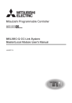
(1) Remote I/O station communication
The ON/OFF status of a switch or indicator lamp is communicated using the
remote input RX and remote output RY (see Section 4.2.1).
PLC CPU
X
Y
1-2
Master station
Remote I/O station
Automatic refresh
Remote input
RX
Link scan
Automatic refresh
Remote output
RY
Link scan
Input
Output
1-2
1 OVERVIEW
MELSEC-Q
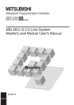
(2) Remote device station communication
Signals for handshaking with the remote device station (initial request, error
occurred flag, etc.) are communicated using the remote input RX and remote
output RY. The setting data to the remote device station are communicated using
remote registers RWw and RWr (see Section 4.2.2).
Master station
PLC CPU
Automatic refresh
Remote
input
(RX)
Link scan
Remote
input
(RX)
Automatic refresh
Remote
output
(RY)
Link scan
Remote
output
(RY)
Link scan
Remote
register
(RWw)
Link scan
Remote
register
(RWr)
X
Y
Automatic refresh
W
Automatic refresh
W
Remote device station
Remote
register
(RWw)
Remote
register
(RWr)
Voltmeter
1-3
1-3
1 OVERVIEW
MELSEC-Q
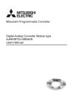
(3) Local station communication
Communication between the master station and the local station uses two types
of transmission methods: cyclic transmission and transient transmission (see
Section 4.2.3).
(a) Cyclic transmission
Data communication between the PLC CPUs can be performed in N:N
mode using bit data (remote input RX and remote output RY) and word data
(remote registers RWw and RWr).
Master station
PLC CPU
Automatic refresh
X
Automatic refresh
Y
Automatic refresh
W
Automatic refresh
W
Local station
Remote
input
(RX)
Link scan
Remote
output
(RY)
Link scan
Remote
register
(RWw)
Remote
register
(RWr)
Link scan
Link scan
PLC CPU
Remote
output
(RY)
Automatic refresh
Remote
input
(RX)
Automatic refresh
Remote
register
(RWr)
Automatic refresh
Remote
register
(RWw)
Automatic refresh
Y
X
W
W
(b) Transient transmission
Read (RIRD) or write (RIWT) operation of the local station buffer memory
and CPU device can be performed at any timing.
PLC CPU
Master station
Local station
Transient transmission
RIWT
Transient transmission
Transient
transmission
area
RIRD
1-4
Transient
transmission
area
W
Transient transmission
Transient transmission
PLC CPU
Buffer
memory
1-4
1 OVERVIEW
MELSEC-Q
(4) Intelligent device station communication
Communication between the master station and the intelligent device station
uses two types of transmission methods: cyclic transmission and transient
transmission (see Section 4.2.4).
(a) Cyclic transmission
Signals for handshaking with the intelligent device station (positioning start,
positioning complete, etc.) are communicated using the remote input RX and
remote output RY. Numeric data (positioning start number, present feed
value, etc.) is communicated using remote registers RWw and RWr.
PLC CPU
Intelligent device station
Master station
Automatic refresh
Remote
input
RX
Link scan
Remote
input
RX
Automatic refresh
Remote
output
RY
Link scan
Remote
output
RY
Link scan
Remote
register
RWw
Link scan
Remote
register
RWr
X
Y
Automatic refresh
W
Automatic refresh
W
Remote
register
RWw
Remote
register
RWr
Servo amplifier
(b) Transient transmission
Read (RIRD) or written (RIWT) operation of the intelligent device station
buffer memory can be performed at any timing.
PLC CPU
Master station
Intelligent device station
RIWT
Transient transmission
Transient
transmission
area
RIRD
1-5
Buffer memory
Transient transmission
1-5
1 OVERVIEW
MELSEC-Q
(5) Parameter setting by GX Developer or the dedicated instruction
There are two parameter setting methods; the parameters can either be set by
GX Developer or by using a dedicated instruction (see Sections 2.2.1, 4.2.5 and
4.2.6).
The following table lists the differences between the two setting methods.
Changing the
Program
requirement for
Automatic
setting
refresh
parameters
Parameter setting with
GX Developer
Parameter setting with
dedicated instruction
Number of
parameter
CPUs that can
settings while
be mounted
the PLC CPU is
running
Not required
4 modules
Required
64 modules
(6) System down prevention (Slave station cut-off function)
Because the system employs the bus connection method, even if a module
system fails due to power off, it will not affect the communication with other
normal modules.
Also, for a module using a 2-piece terminal block, the module can be replaced
during data link. (Replace the module after turning off the module power).
However, if the cable is disconnected, data link to all stations are disabled (see
Section 4.3.1).
Master
station
Station number 1
Station number 3
Remote station
(occupies 2 stations)
Remote station
(occupies 1 station)
Station number 4
Station number 7
Local
station
(occupies
1 station)
Local
station
(occupies
4 stations)
Station number 5
Remote station
(occupies 2 stations)
Data link continues
Faulty
station
Master
station
Station number 1
Station number 3
Remote station
(occupies 2 stations)
Remote station
(occupies 1 station)
Station number 4
Station number 7
Local
station
(occupies
1 station)
Local
station
occupies
4 stations)
Station number 5
Remote station
(occupies 2 stations)
(7) Automatic return function
When a station that has been disconnected from the link due to power off
recovers the normal status, it will join the data link automatically (see Section
4.3.2).
1-6
1-6
1 OVERVIEW
MELSEC-Q
(8) Data link status setting when the master station PLC CPU has an
error
The data-link status can be set to either "stop" or "continue" when an error
causing the operation to stop such as "SP. UNIT ERROR" occurs in the PLC
CPU at the master station. With errors enabling the operation to continue such as
"BATTERY ERROR," the data link will continue regardless of the setting (see
Section 4.3.3).
(9) Setting the status of input data from a data link faulty station
The data entered (received) from a data-link faulty station can be cleared or the
previous status immediately before the error can be maintained (see Section
4.3.4).
(10) Standby master function
This function enables the data link to continue working by switching to a standby
master station (backup station for the master station) if a malfunction occurs in
the master station due to a malfunction of the PLC CPU or power supply.
The master station can return to online even during data link control by the
standby master station, and prepares itself for standby master station system
down (see Section 4.3.6).
Standby master station
Station number 1
Number of occupied stations: 1
Data link control by the master station
Master station
Remote device station
Station number 2
Number of occupied stations: 2
Data link
control in
progress
Cyclic communication
Master station is down
Master station
Intelligent device station
Station number 4
Number of occupied stations: 1
Cyclic communication
Cyclic communication
Data link control by the standby master station
Remote device station
Station number 2
Number of occupied stations: 2
Cyclic communication
Standby master station
Station number 1 0
Intelligent device station
Station number 4
Number of occupied stations: 1
Cyclic communication
Standby
Data link
control in
progress
Cyclic communication
To the next page
1-7
1-7
1 OVERVIEW
MELSEC-Q
Continued from the previous page
Master station returns to normal and comes back online
Master station prepares itself for standby master station system down
Master station
Station number 0 1
Standby
Remote device station
Station number 2
Number of occupied stations: 2
Cyclic communication
Problem occurrence in the standby master station
Master station
Station number 1 0
Data link
control in
progress
Intelligent device station
Station number 4
Number of occupied stations: 1
Cyclic communication
Cyclic communication
Standby master station
Intelligent device station
Station number 4
Number of occupied stations: 1
Cyclic communication
Cyclic communication
Standby master station returns to normal and comes back online
Standby master station prepares itself for master station system down
Master station
Data link
control in
progress
Remote device station
Station number 2
Number of occupied stations: 2
Cyclic communication
1-8
Data link
control in
progress
Data link control by the master station
Remote device station
Station number 2
Number of occupied stations: 2
Cyclic communication
Standby master station
Station number 0
Standby master station
Station number 1
Number of occupied stations: 1
Intelligent device station
Station number 4
Number of occupied stations: 1
Cyclic communication
Standby
Cyclic communication
1-8
1 OVERVIEW
MELSEC-Q
(11) Remote device station initialization procedure registration function
This function performs the initial setting for the remote device station using the
GX Developer, without creating a sequence program (see Section 4.4.1).
(12) Event issuance for the interrupt program
This function issues an event when the conditions set by the GX Developer are
established in order to make the PLC CPU execute the interrupt program (see
Section 4.4.2).
(13) Automatic CC-Link startup
By installing the QJ61BT11N, the CC-Link is started up and all data are refreshed
by simply turning on the power, without creating a sequence program. However,
when the number of connected modules is less than 64, it is necessary to set the
network parameters in order to optimize the link scan time (see Section 4.4.3.).
(14) Selecting a mode according to the system
The CC-Link system has four types of modes according to various systems. (See
sections 4.4.4, 4.4.5 and 4.4.14.)
The overview of the modes is described in the following table.
Mode
Connectable
Remote net ver. 1 mode
Remote I/O station
Overview
Mode in which complete compatibility with the
conventional module (QJ61BT11) is achieved.
Select this mode when the number of cyclic points need
not be increased or when the QJ61BT11N is used to
replace the conventional module as a maintenance
product.
Select this mode when increasing the number of cyclic
points and configuring a new system.
Select this mode when adding a ver.2 compatible slave
station to the existing system to increase the number of
cyclic points.
Select this mode when the system consists of only the
master station and remote I/O stations.
Since cyclic transmission is made at high speed, the link
scan time can be reduced.
Remote device station
Intelligent device station
Local station
Remote net ver. 2 mode
Standby master station
Remote net additional mode
Remote I/O net mode
Remote I/O station
(15) Reserved station function
Stations that are not actually connected (stations to be connected in the future)
will not be treated as faulty stations if they are specified as reserved stations.
The reserved stations can also be set as 0 points. (see Section 4.4.6).
Stations that will be connected in the future
(Reserved station)
Station number 4
Master
station
1-9
Station number 1
Remote station
(occupies 2 stations)
Station number 3
Remote station
(occupies 1 station)
Local
station
(occupies
4 stations)
Station number 8
Remote station
(occupies 2 stations)
(Reserved station)
Station number 10
Remote station
(occupies 1 station)
1-9
1 OVERVIEW
MELSEC-Q
(16) Error invalid station setting function
By setting the network parameters, the module that is powered off in the system
configuration will not be treated as a "data link faulty station" by the master
station and local station. However, caution is required since errors are no longer
detected (see Section 4.4.7).
Stations to be specified as error invalid stations
Master
station
Station number 1
Remote station
(occupies 2 stations)
Station number 4
Station number 7
Local
station
(occupies
1 station)
Local
station
(occupies
4 stations)
Station number 3
Remote station
(occupies 1 station)
Station number 5
Remote station
(occupies 2 stations)
This station does not become a data link faulty station.
Master
station
Station number 1
Remote station
(occupies 2 stations)
Station number 4
Station number 7
Local
station
(occupies
1 station)
Local
station
(occupies
4 stations)
Station number 3
Remote station
(occupies 1 station)
Station number 5
Remote station
(occupies 2 stations)
(17) Scan synchronous function
This function synchronizes the link scan to the sequence scan (see Section
4.4.8).
(18) Temporary error invalid station setting function
With this function, the module specified by the GX Developer will not be treated
as a "data link faulty station" by the master or local station while in online. The
module can be replaced without detecting an error in online (see Section 4.4.9).
(19) Data link stop/restart
The data link can be stopped and restarted while it is being used (see Section
4.4.10).
(20) Station number overlap checking function
This function checks the status of the connected stations to see if the number of
occupied stations is overlapping or if there is more than one station with the
station number setting of 0 in the system (see Section 4.4.11).
1 - 10
1 - 10
1 OVERVIEW
MELSEC-Q
(21) Transient transmission
With this method of transmission, the counterpart is specified and 1:1
communication is performed at an arbitrary timing (see Section 4.5).
Master station
PLC CPU
Master module
RIWT
Send buffer
Local station
Buffer memory
Device memory
Master station
PLC CPU
Local station
Master module
RIRD
Buffer memory
Device memory
Send buffer
1 - 11
1 - 11
1 OVERVIEW
MELSEC-Q
(22) Compatibility with conventional module
The QJ61BT11N achieves complete compatibility with the conventional module
(QJ61BT11) in the remote net ver. 1 mode.
Select the remote net ver. 1 mode when the number of cyclic points need not be
increased or when the QJ61BT11N is used to replace the conventional module
as a maintenance product.
(23) Cyclic points increase
Selection of the remote net ver. 2 mode or remote net additional mode allows
RX/RY to be increased to up to 8192 points and RWr/RWw to up to 2048 words
per network by making expanded cyclic setting (single, double, quadruple,
octuple).
Also, RX/RY can be increased to up to 224 points and RWr/RWw to up to 32
words per station. (See Section 4.4.14.)
(24) Remote I/O station points setting
Set the number of I/O points of a remote I/O station.
This setting minimizes CPU device assignment and reduces the reserved points
of remote input RX and remote output RX for remote I/O stations. (See Section
4.4.13.)
(25) Slave station refresh/compulsory clear setting in case of PLC CPU
STOP
Set whether output data to the remote, local, intelligent device and standby
master stations will be refreshed or compulsorily cleared when the PLC CPU
comes to STOP. (See Section 4.3.5.)
1 - 12
1 - 12
2 SYSTEM CONFIGURATION
MELSEC-Q
2 SYSTEM CONFIGURATION
The system configuration for the CC-Link is described below.
2.1 System Configuration
2
(1) Remote net ver. 1 mode
A total of 64 remote I/O stations, remote device stations, local stations, standby
master stations, or intelligent device stations can be connected to a single master
station.
However, the following conditions must all be satisfied.
Condition 1
{(1
Condition 2
{(16
a) + (2
b) + (3
A) + (54
c) + (4
d)} ≤ 64
C)} ≤ 2304
B) + (88
a: Number of modules occupying 1 station
b: Number of modules occupying 2 stations
c: Number of modules occupying 3 stations
d: Number of modules occupying 4 stations
A: Number of remote I/O stations ≤ 64
B: Number of remote device stations ≤ 42
C: Number of local stations, standby master stations
and intelligent device stations ≤ 26
Maximum 26
1 module for each system
Master station
Master station
Master station
Local station
Local station
Local station
QJ61BT11N
QJ61BT11
A1SJ61QBT11
AJ61QBT11
A1SJ61BT11
AJ61BT11
QJ61BT11N
QJ61BT11
A1SJ61QBT11
AJ61QBT11
A1SJ61BT11
AJ61BT11
CC-Link dedicated cable
Terminal resistor (required)
Maximum 26
Maximum 42
Maximum 64
Intelligent device station
Remote device station
Remote I/O station
RS-232C
Interface module
AJ65BT-R2
Analog/digital
converter module
AJ65BT-64AD
Remote I/O module
AJ65BTB1-16D
AJ65BTC-32D
Terminal resistor (required)
CC-Link dedicated cable
Total 64
2-1
2-1
2 SYSTEM CONFIGURATION
MELSEC-Q
(2) Remote net ver. 2 mode, remote net additional mode
A total of 64 remote I/O stations, remote device stations, local stations, standby
master stations, or intelligent device stations can be connected to a single master
station.
However, the following conditions must all be satisfied.
{(a + a2 + a4 + a8)
2
Condition 1
+ (b + b2 + b4 + b8)
2
+ (c + c2 + c4 + c8)
3
+ (d + d2 + d4 + d8)
4} ≤ 64
[{(a
Condition 2
+ {(c
96) + (c2
160) + (c4
+ {(d
128) + (d2
224) + (d4
4) + (a2
8) + (a4
16) + (a8
+ {(b
8) + (b2
12) + (c2
24) + (c4
48) + (c8
+ {(d
16) + (d2
32) + (d4
64) + (d8
A) + (54
16) + (b4
32)}
+ {(c
Condition 4 {(16
2-2
32) + (a4
96) + (b4
[{(a
Condition 3
32) + (a2
64) + (b2
+ {(b
a: The total number of ver.1 compatible slave
stations that occupy 1 station, and ver.2
compatible slave stations that occupy 1 station
which are set to “Single”.
b: The total number of ver.1 compatible slave
64) + (a8 128)}
stations that occupy 2 stations, and ver.2
compatible slave stations that occupy 2 stations
192) + (b8 384)}
which are set to “Single”.
320) + (c8 640)}
c: The total number of ver.1 compatible slave
448) + (d8 896)}] ≤ 8192
stations that occupy 3 stations, and ver.2
compatible slave stations that occupy 3 stations
which are set to “Single”.
d: The total number of ver.1 compatible slave
stations that occupy 4 stations, and ver.2
compatible slave stations that occupy 4 stations
which are set to “Single”.
B) + (88
+ 32) + (b8
C) } ≤ 2304
a2: The number of ver.2 compatible stations that
occupy 1 station which are set to “Double”.
b2: The number of ver.2 compatible stations that
occupy 2 stations which are set to “Double”.
c2: The number of ver.2 compatible stations that
occupy 3 stations which are set to “Double”.
d2: The number of ver.2 compatible stations that
occupy 4 stations which are set to “Double”.
64)}
a4: The number of ver.2 compatible stations that
occupy 1 station which are set to “Quadruple”.
128)}] ≤ 2048 b4: The number of ver.2 compatible stations that
occupy 2 stations which are set to “Quadruple”.
c4: The number of ver.2 compatible stations that
occupy 3 stations which are set to “Quadruple”.
d4: The number of ver.2 compatible stations that
occupy 4 stations which are set to “Quadruple”.
96)}
a8: The number of ver.2 compatible stations that
occupy 1 station which are set to “Octuple”.
b8: The number of ver.2 compatible stations that
occupy 2 stations which are set to “Octuple”.
c8: The number of ver.2 compatible stations that
occupy 3 stations which are set to “Octuple”.
d8: The number of ver.2 compatible stations that
occupy 4 stations which are set to “Octuple”.
A: Number of remote I/O stations ≤ 64
B: Number of remote device stations ≤ 42
C: Number of local stations, standby master
stations and intelligent device stations ≤ 26
2-2
2 SYSTEM CONFIGURATION
MELSEC-Q
1 module for each system
Maximum 26
Master station
Local station
Local station
Local station
QJ61BT11N
QJ61BT11N
QJ61BT11
A1SJ61QBT11
AJ61QBT11
A1SJ61BT11
AJ61BT11
CC-Link dedicated cable
Terminal resistor (required)
Maximum 26
Maximum 42
Maximum 64
Intelligent device station
Remote device station
Remote I/O station
RS-232C
Interface module
AJ65BT-R2
Analog/digital
converter module
AJ65VBTCU-68ADVN
AJ65VBTCU-68ADIN
Remote I/O module
AJ65BTB1-16D
AJ65BTC-32D
Terminal resistor (required)
CC-Link dedicated cable
Total 64
2-3
2-3
2 SYSTEM CONFIGURATION
MELSEC-Q
2.2 Applicable System
Applicable PLC CPUs and notes on the system configuration are described below.
2.2.1 Applicable modules and number of CPUs that can be mounted
(1) Applicable modules and number of CPUs that can be mounted
The CPU modules and network modules (for remote I/O station) to which the
QJ61BT11N can be installed and number of modules that can be installed are
listed in the table below.
(a) When performing the parameter setting with the GX Developer
Applicable module
Number of CPUs that can be mounted
Remark
Q00JCPU
Q00CPU
1
2
)(
(
Maximum 2
)
Q01CPU
Q02CPU
It can be mounted
Q02HCPU
CPU
Q06HCPU
module
Q12HCPU
only with the
Maximum 4
Q mode.
( 1) ( 3)
Q25HCPU
Q12PHCPU
Q25PHCPU
Q12PRHCPU
Q25PRHCPU
Network
module
Maximum 4
1
(
6
)(
(
Maximum 4
1
)
)(
4
(
4
)(
5
)
QJ72LP25-25
QJ72LP25G
Maximum 4
)
QJ72BR15
1 Refer to the QCPU User's Manual (Function Explanation, Program Fundamentals).
2 For use in the remote net additional mode, select a PLC CPU with first 5 digits of
serial No. "06112" or later.
If any incompatible PLC CPU is used, the operation can not guaranteed.
3 For use in the remote net additional mode, use a PLC CPU with first 5 digits of serial
No. "05032" or later.
If any incompatible PLC CPU is used, the operation cannot be guaranteed.
4 Incompatible with the remote net additional mode. When the module is used, the
operation cannot be guaranteed.
5 For use in a redundant system, select the QJ61BT11N with first 5 digits of serial No.
"06052" or later.
When any incompatible QJ61BT11N is used, the operation cannot be guaranteed.
6 For use in the remote net additional mode, use a PLC CPU with first 5 digits of serial
No. "07032" or later.
If any incompatible PLC CPU is used, the operation cannot be guaranteed.
2-4
2-4
2 SYSTEM CONFIGURATION
MELSEC-Q
(b) When performing the parameter setting with the dedicated instructions.
Applicable module
Number of CPUs that can be mounted
Remark
Q00JCPU
(
Maximum 2
Q00CPU
1
)
Q01CPU
Q02CPU
CPU
Q02HCPU
module
Q06HCPU
It can be mounted only
Maximum 64
Q12HCPU
with the Q mode.
( 1)
Q25HCPU
Q12PHCPU
(
Maximum 64
Q25PHCPU
1
)
1 Refer to the QCPU User's Manual (Function Explanation, Program Fundamentals).
(2) Mountable base unit
QJ61BT11N can be mounted on any of the base unit’s I/O slots ( 7). However,
depending on combinations with other mounted modules and the number of
mountings, there may be cases where the power capacity is insufficient. Be sure
to consider the power capacity when mounting the module.
7 Must be inside the point number range of 1 CPU unit and network module (for remote
I/O station).
(3) Applicable software package
The software package available for the QJ61BT11N is listed below:
Manual name
Model name
Remarks
Required MELSEC PLC programming
GX Developer
SWnD5C-GPPW-E
8
software.
"n" in the model name is 4 or greater.
8 The product of Version 8.03D or later is required for use in the remote net ver.2 mode
or remote net additional mode.
(4) Usable slave stations
Any of ver.1 compatible slave stations and ver.2 compatible slave stations is
usable.
2-5
2-5
2 SYSTEM CONFIGURATION
MELSEC-Q
2.2.2 Notes on the system configuration
The system should be designed with the following considerations to prevent mis-input
from the remote I/O modules:
(1) When powering on and off
Start the data link after turning on the power to the remote I/O modules. Turn off
the power to the remote I/O modules after stopping the data link.
Data link start
Data link stop
During operation
Master module
(data link status)
During stop
ON
Remote I/O module
(power status)
OFF
(2) During momentary power failure of the remote I/O modules
When a momentary power failure occurs in the power (24 V DC) being supplied
to the remote I/O modules, mis-input may occur.
(a) Cause for mis-input due to a momentary power failure
The remote I/O module hardware uses the power by internally converting
the module power (24 V DC) to 5 V DC.
When a momentary power failure occurs in a remote I/O module, the
following condition occurs:
(Time for the 5 V DC power in the remote I/O module to turn off) >
(Response time for input module on off)
Therefore, mis-input occurs when a refresh is performed within the time
indicated by 1) in the figure below.
1)
Remote I/O module
(module power supply and input
external supply power)
Remote I/O module (internal 5 V DC)
Input (Xn)
When the input external power supply turns OFF, the
input (Xn) turns OFF after the response time for the
input module to change from ON to OFF.
2-6
2-6
2 SYSTEM CONFIGURATION
MELSEC-Q
~
For DC input
PLC CPU
Master module
Power supply module
(b) Countermeasure for mis-input
For the power supply module, the stabilized power supply and the input
external supply power of AC input, wire the power cables from the same
power source.
Module power supply
~
Input externalsupply power
24 V DC
PLC CPU
Master module
Power supply module
Stabilized
power supply
Remote I/O module
Remote I/O module
For AC input
Module power supply
Stabilized
power supply
Input externalsupply power
24 V DC
REMARK
When supplying power from a single power source to multiple remote I/O modules,
select the proper type of cable and perform the wiring in consideration of the voltage
decline.
Connections can be established if the receiving port voltage at the remote I/O
module is within the specified range of the remote I/O module to be used.
~
Stabilized
power supply
Remote module
2-7
Remote module
2-7
2 SYSTEM CONFIGURATION
MELSEC-Q
(3) Access to station No.64
(a)
(b)
To a local station of No. 64, other station access from GX Developer or
GOT is not allowed.
If the station No. is changed to other than 64, other station access is
executable.
The CC-Link board is not allowed to access a local station or intelligent
device station whose station No. is 64.
If the station No. is changed to other than 64, other station access is
executable.
(4) Precautions for use on remote I/O stations
Pay attention to the following for use on remote I/O stations:
• Interrupt setting of network parameters is not available.
• Transient transmissions using dedicated instructions are not allowed to local
stations and intelligent device stations.
2.2.3 How to check the function version
The following describes how to check the function version.
(1) How to check the function version of the QJ61BT11N
(a) Checking the "SERIAL column of the rating plate" on the module side
Serial No. (first 5 digits)
MODEL
Function version
SERIAL 050320000000000-B
Conformed standard
MADE IN JAPAN
(b) See Section 13.4 for how to check the function version with GX Developer.
2-8
2-8
2 SYSTEM CONFIGURATION
MELSEC-Q
2.2.4 CC-Link version
There are two types of CC-Link version, i.e., Ver.1 and Ver.2.
(1) Definition of Ver.1.00 and Ver.1.10
Version 1.10 modules have a uniform station-to-station cable length of 20 cm or
more by improving the restrictions on the conventional station-to-station cable
length.
In contrast, the conventional modules are defined as Version 1.00.
See Section 3.1.2 for the maximum overall cable distance of Version 1.10.
In order to make the station-to-station cable length uniformly 20 cm or more, the
following conditions are required:
1) All the modules that configure the CC-Link system must be compatible with
Ver.1.10.
2) All the data link cables must be CC-Link dedicated cables conforming to Version
1.10.
POINT
The specifications for Version 1.00 should be used for the maximum cable overall
distance and station-to-station cable length if a system contains modules and
cables of both Version 1.00 and Version 1.10.
See Section 3.1.1 for the maximum overall cable distance and station-to-station
cable length of Version 1.00.
(2) Definition of Ver.2
As Ver.2 is characterized as increase of cyclic transmission data size,
Ver.2-compatible module is defined to support this function.
(3) Checking version
The modules including CC-Link logo on the rated plate are compatible with
Ver.1.10.
The modules including V2 logo on the rated plate are compatible with Ver.2.
MODEL
SERIAL 050320000000000-B
Conformed standard
MADE IN JAPAN
2-9
2-9
3 SPECIFICATIONS
MELSEC-Q
3 SPECIFICATIONS
This section describes the specifications of the QJ61BT11N.
For the general specifications of the QJ61BT11N, refer to the user's manual for the
CPU module to be used.
3.1 Performance Specifications
Table 3.1 lists the performance specifications of the OJ61BT11N.
Table 3.1 Performance specifications
3
Item
Specification
Transmission rate
Can select from 156 kbps/ 625 kbps/ 2.5 Mbps/ 5 Mbps/ 10 Mbps
Maximum overall cable distance
(Maximum transmission distance)
Varies according to the transmission rate (See Section 3.1.1, 3.1.2)
Maximum number of connected stations
(master station)
64 (See Section 2.1)
Number of occupied stations
(local station)
1 to 4 stations
The number of stations can be switched using the GX Developer parameter setting.
Remote I/O (RX, RY)
Maximum number of link points per system
: 2048 points
Remote register (RWw) : 256 points
(master station
remote device station/local station/ intelligent
device station/standby master station)
Remote register (RWr)
(remote device station/local station/ intelligent device station/standby
master station)
master station
1
: 256 points
Remote I/O (RX, RY)
: 32 points
Remote station/local station/intelligent device Remote register (RWw) : 4 points
station/standby master station
1
Number of link points per station
Remote register (RWr) : 4 points
(local station is 30 points)
(master station
remote device station/local station/ intelligent
device station/standby master station)
(remote device station/local station/ intelligent device station/standby
master station
master station)
Communication method
Broadcast polling method
Synchronous method
Flag synchronous method
Encoding method
NRZI method
Transmission path
Bus (RS-485)
Transmission format
Conforms to HDLC
Error control system
CRC (X16 + X12 + X5 + 1)
Connection cable
RAS function
Number of I/O occupied points
1
CC-Link dedicated cable/ CC-Link dedicated high-performance cable/
2
Ver.1.10 compatible CC-Link dedicated cable
Automatic return function
Slave station cut-off function
Error detection by the link special relay/register
32 points (I/O assignment: Intelligent 32 points)
5 V DC internal current consumption
0.46 A
Weight
0.12 kg
1 Indicates the number of link points for remote net ver.1 mode. For number of link points for remote net
ver.2 mode/remote net additional mode. Refer to the table 3.2.
2 CC-Link dedicated high-performance cables cannot be used with other cables such as CC-Link dedicated
cables or Ver.1.10 compatible CC-Link dedicated cables. Also attach the terminating resister which
matches the kind of the cable. (Refer to section 7.5)
3-1
3-1
3 SPECIFICATIONS
MELSEC-Q
Table 3.2 Number of link points for remote net ver.2 mode/remote net additional mode
Item
Specifications
Remote I/O (RX, RY)
: 8192 points
Remote register (RWw) : 2048 points (master station
remote device
station/local station/intelligent device
Maximum No. of link points per system
station/standby master station)
Remote register (RWr) : 2048 points (remote device station/local
station/intelligent device station/standby
master station
Expanded cyclic setting
No. of link
points per
Remote I/O (RX, RY)
station
Quadruple
Octuple
64 points
128 points
(30 points
(30 points
(62 points
(126 points
for local
for local
for local
for local
station)
station)
station)
station)
8 points
16 points
32 points
Remote register (RWr)
4 points
8 points
16 points
32 points
32 points
32 points
64 points
128 points
4 points
8 points
16 points
32 points
4 points
8 points
16 points
32 points
64 points
96 points
192 points
384 points
8 points
16 points
32 points
64 points
8 points
16 points
32 points
64 points
96 points
160 points
320 points
640 points
12 points
24 points
48 points
96 points
12 points
24 points
48 points
96 points
128 points
224 points
448 points
896 points
16 points
32 points
64 points
128 points
16 points
32 points
64 points
128 points
Occupies
Remote
1 station
register (RWw)
Remote
register (RWr)
Remote I/O
(RX, RY)
Occupies
Remote
2 stations
register (RWw)
of link
Remote
points per
register (RWr)
number of
Remote I/O
occupied
(RX, RY)
Occupies
Remote
3 stations
register (RWw)
Remote
register (RWr)
Remote I/O
(RX, RY)
Occupies
Remote
4 stations
register (RWw)
Remote
register (RWr)
3-2
Double
32 points
4 points
(RX, RY)
stations
Single
32 points
Remote register (RWw)
Remote I/O
Number
master station)
3-2
3
3 SPECIFICATIONS
MELSEC-Q
3.1.1 Maximum overall cable distance (for Ver. 1.00)
The relationship between the transmission speed and the maximum overall cable
distance is described below:
(1) For a system consisting of only remote I/O stations and remote
device stations
Remote I/O station
or remote
device station
Remote I/O station
or remote
device station
Master station
2
2
Remote I/O station
or remote
device station
1
Remote I/O station
or remote
device station
1
Maximum overall cable distance
1 Cable length between remote I/O stations or remote device stations.
2 Cable length between the master station and the adjacent stations.
CC-Link dedicated cable (uses terminal resistor 110 Ω)
Transmission rate
Station-to-station cable length
1
2
156 kbps
625 kbps
1200 m (3937.2 ft.)
30 cm (11.81 in.) or more
600 m (1968.6 ft.)
2.5 Mbps
200 m (656.2 ft.)
30 cm (11.81 in.) to
5 Mbps
110 m (360.9 ft.)
59 cm (23.23 in.)
60 cm (23.62 in.) or more
1 m (3.28 ft.) or more
30 cm (11.81 in.) to
150 m (492.15 ft.)
50 m (164.1 ft.)
59 cm (23.23 in.)
10 Mbps
Maximum overall cable
distance
60 cm (23.62 in.) to
80 m (262.5 ft.)
99 cm (38.98 in.)
1 m (3.28 ft.) or more
100 m (328.1 ft.)
CC-Link dedicated high performance cable (uses terminal resistor 130 Ω)
Transmission rate
Station-to-station cable length
1
2
156 kbps
Maximum overall cable
distance
1200 m (3937.2 ft.)
625 kbps
900 m (2952.9 ft.)
2.5 Mbps
400 m (1312.4 ft.)
30 cm (11.81 in.) or more
5 Mbps
160 m (524.96 ft.)
Number of connected
stations: 1 to 32
Number of connected
stations: 33 to 48
10 Mbps
Number of connected
stations: 49 to 64
100 m (328.1 ft.)
30 cm (11.81 in.) to
39 cm (15.35 in.)
1 m (3.28 ft.) or more
80 m (262.5 ft.)
40 cm (15.75 in.) or more
100 m (328.1 ft.)
30 cm (11.81 in.) to
39 cm (15.35 in.)
20 m (65.52 ft.)
40 cm (15.75 in.) to
69 cm (27.17 in.)
30 m (98.43 ft.)
70 cm (27.56 in.) or more
100 m (328.1 ft.)
The cable length between remote I/O stations or remote device stations is within
this range and if even one location is wired, the maximum overall cable distance will
be as indicated above.
3-3
3-3
3 SPECIFICATIONS
MELSEC-Q
(Example) When the transmission rate is 10 Mbps, and 43 remote I/O stations and
remote device stations are connected using the CC-Link dedicated high
performance cable, because the cable connecting the second and third
stations is "35 cm (13.78 in.)", the maximum overall cable distance will
be "80 cm (31.5 in.)".
Master station
First
Second
Third
4th
43th
Remote I/O station
Remote device
station
Remote I/O station
Remote I/O station
Remote device
station
1 m (3.28 ft.)
50 cm (19.69 in.)
35 cm (13.78 in.)
50 cm (19.69 in.)
(2) For a system consisting of remote I/O stations, remote device
stations, local stations and intelligent device stations
Remote I/O station
or remote
device station
Master station
2
1
Local station
or intelligent
device station
Local station
or intelligent
device station
Remote I/O station
or remote
device station
2
2
Maximum overall cable distance
1 Cable length between remote I/O stations or remote device stations
2 Cable length between the master station or the local or intelligent device station
and the adjacent stations
CC-Link dedicated cable (uses terminal resistor 110 Ω)
Transmission rate
Station-to-station cable length
1
2
156 kbps
625 kbps
1200 m (3937.2 ft.)
30 cm (11.81 in.) or more
600 m (1968.6 ft.)
2.5 Mbps
5 Mbps
200 m (656.2 ft.)
30 cm (11.81 in.) to
110 m (360.9 ft.)
59 cm (23.23 in.)
60 cm (23.62 in.) or more
2 m (6.56 ft.) or more
30 cm (11.81 in.) to
10 Mbps
Maximum overall cable
distance
150 m (492.15 ft.)
50 m (164.1 ft.)
59 cm (23.23 in.)
60 cm (23.62 in.) to
80 m (262.5 ft.)
99 cm (38.98 in.)
1 m (3.28 ft.) or more
100 m (328.1 ft.)
CC-Link dedicated high performance cable (uses terminal resistor 130 Ω)
Transmission rate
Station-to-station cable length
1
2
156 kbps
625 kbps
1200 m (3937.2 ft.)
30 cm (11.81 in.) or more
600 m (1968.6 ft.)
2.5 Mbps
200 m (656.2 ft.)
30 cm (11.81 in.) to
5 Mbps
59 cm (23.23 in.)
60 cm (23.62 in.) or more
70 cm (27.56 in.) to
10 Mbps
Maximum overall cable
distance
99 cm (38.98 in.)
1 m (3.28 ft.) or more
2 m (6.56 ft.) or more
110 m (360.9 ft.)
150 m (492.15 ft.)
50 m (164.1 ft.)
80 m (262.5 ft.)
The cable length between remote I/O stations or remote device stations is within
this range and if even one location is wired, the maximum overall cable distance will
be as indicated above.
3-4
3-4
3 SPECIFICATIONS
MELSEC-Q
3.1.2 Maximum overall cable distance (for Ver. 1.10)
The relation of the transmission speed and maximum overall cable distance when
configuring the entire system with Version 1.10 modules and cable is shown below.
Master station
Remote I/O station
or remote
device station
Remote I/O station
or remote
device station
Local station or
intelligent device
station
Local station or
intelligent device
station
Station to station
cable length
Maximum overall cable distance
Version 1.10 compatible CC-Link dedicated cable (terminal resistor of 110Ω used)
Transmission speed
Maximum overall cable distance
156kbps
1200m
625kbps
900m
2.5Mbps
3-5
Station to station cable length
20cm or longer
400m
5Mbps
160m
10Mbps
100m
3-5
3 SPECIFICATIONS
MELSEC-Q
3.2 CC-Link Dedicated Cable
Use the CC-Link dedicated cable for the CC-Link system. If a cable other than the CCLink dedicated cable is used, the performance of the CC-Link system cannot be
guaranteed.
If you have any questions regarding the CC-Link dedicated cable, or if you wish to see
its specifications, see the CC-Link Partner Association homepage http://www.cclink.org/.
REMARK
For details, refer to the CC-Link cable wiring manual issued by CC-Link Partner
Association.
3-6
3-6
3 SPECIFICATIONS
MELSEC-Q
MEMO
3-7
3-7
4 FUNCTIONS
MELSEC-Q
4 FUNCTIONS
This chapter explains the functions of QJ61BT11N, dividing them into four sections:
"Basic Functions", "Functions for Improving System Reliability", "Handy Functions" and
"Transient Transmission Functions".
Some functions are unavailable depending on the mounted CPU.
Refer to Appendix 6 for details.
4.1 Function List
(1) Table 4.1 lists the "basic functions".
Table 4.1 List of the "basic functions"
Item
Description
Communication with remote I/O
station
Performs on/off data communication with remote I/O station.
Communication with remote device Performs on/off data and numeric data communication with
station
remote device station.
Communication with local station
Performs on/off data and numeric data communication with local
station.
Communication with intelligent
Performs communication with intelligent device station, cyclic
device station
transmission, and transient transmission.
Parameter setting with GX
Sets the network parameter, automatic refresh parameter with
Developer
the GX Developer.
Parameter setting with dedicated
instruction
Sets the network parameter with the RLPASET instruction.
Reference section
Section 4.2.1
4
Section 4.2.2
Section 4.2.3
Section 4.2.4
Section 4.2.5
Section 4.2.6
(2) Table 4.2 lists the "functions for improving system reliability".
Table 4.2 List of the "functions for improving system reliability"
Item
Description
Reference section
Disconnects the module that cannot continue the data link
Slave station cut-off function
because of power off, and continues the data link with only the
Section 4.3.1
normal modules.
When a module, which has been disconnected from the data link
Automatic return function
because of power off, returns to the normal status, it
Section 4.3.2
automatically joins the data link.
Data link status setting when the
master station PLC CPU has an
error
Sets the data link status when an error that stops the operation
occurs at the master station PLC CPU.
Setting the status of input data from Sets the status (clear/hold) of the input (receive) data from a
a data link faulty station
Slave station refresh/compulsory
clear setting in case of PLC CPU
STOP
Standby master function
4-1
station that became data link faulty because of power off.
Sets whether output data to the slave stations will be refreshed
or compulsorily cleared when the PLC CPU comes to STOP.
Continues the data link by switching to the standby master
station when a problem occurs in the master station.
Section 4.3.3
Section 4.3.4
Section 4.3.5
Section 4.3.6
4-1
4 FUNCTIONS
MELSEC-Q
(3) Table 4.3 lists the "handy functions".
Table 4.3 List of the "handy functions"
Item
Description
Remote device station initialization Performs initial setting of remote device station using GX
procedure registration function
Event issuance for the interrupt
program
Developer.
Reference section
Section 4.4.1
Issues events when the conditions set by GX Developer are
established and causes the PLC CPU to run an interrupt
Section 4.4.2
program.
Automatic CC-Link startup
Starts the CC-Link automatically by turning the power on.
Performs communication with all stations (remote station, local
Remote net mode
station, intelligent device station, and standby master station).
Shortens the link scan time for a system consisting only of the
Remote I/O net mode
master station and remote I/O stations.
By assigning modules that will be connected in the future as
reserved stations, they will not be treated as data link faulty
stations. If any of the connected modules is specified, it cannot
perform data link.
The reserved stations can also be set as 0 points.
4
Reserved station function
Section 4.4.3
Section 4.4.4
Section 4.4.5
Section 4.4.6
Prevents modules that may be powered off in the system
Error invalid station setting function configuration from being treated as data link faulty stations by
Scan synchronous function
setting the network parameters.
Performs link scan by synchronizing with
Synchronous mode
sequence scan.
Perform link scan without synchronizing
Asynchronous mode
with sequence scan.
Temporary error invalid station
Prevents modules specified by GX Developer from being treated
setting function
as data link faulty stations temporarily during online operation.
Data link stop/restart
Stops or restarts the data link that is being executed.
Station number overlap checking
function
Section 4.4.7
Section 4.4.8
Section 4.4.9
Section 4.4.10
Checks for the overlapping of number of occupied stations and
whether or not more than one module having a station number
Section 4.4.11
setting of 0 exists in the system.
Allows monitoring and reading/writing programs from/to any
Multiple PLC system support
Remote I/O station points setting
Cyclic points increase
CPU in a multiple PLC system mounted with the QJ61BT11N via
AJ65BT-G4-S3 or other station CPUs.
Allows the I/O points of the remote I/O stations to be selected
from among 8 points, 16 points and 32 points, reducing the
number of reserved points.
Allows the number of cyclic points per module to be increased
from 128 points for RX/RY and 16 points for RWr/RWw in the
ver. 1 mode to up to 896 points for RX/RY and 128 points for
RWr/RWw in the ver. 2 mode.
Section 4.4.12
Section 4.4.13
Section 4.4.14
(4) Table 4.4 lists the "functions for transient transmission".
Table 4.4 List of the "functions for transient transmission"
Item
Transient transmission
4-2
Description
Reference section
Specifies a counterpart and communicates at an arbitrary timing.
Section 4.5.1
4-2
4 FUNCTIONS
MELSEC-Q
4.2 Basic Functions
This section explains the basic functions of the QJ61BT11N.
4.2.1 Communication with the remote I/O stations
Two types of communication modes are available for the CC-Link system: remote net
mode and remote I/O net mode.
(1) Remote net mode
In this mode, it is possible to communicate with all stations (remote I/O station,
remote device station, local station, intelligent device station, and standby master
station). Thus, various systems can be configured according to their applications.
(2) Remote I/O net mode
In this mode, a high-speed cyclic transmission is performed for a system
consisting only of the master station and remote I/O stations. Because of this, the
link scan time can be shortened when compared to the remote net mode.
The following provides an overview of the communication between the master
station and a remote I/O station using the remote I/O net mode. In the
communication with the remote I/O station, the on/off data of the switches and
indicator lamps are communicated through remote input RX and remote output
RY.
PLC CPU
Network
parameters
Master station
1)
Automatic
refresh
parameters
Network
parameters
Buffer memory
3)
X
Automatic refresh
2)
Remote input
RX
Automatic refresh
Link scan
Input
5)
4)
Y
Remote I/O station
Remote output
RY
Link scan
Output
[Data link startup]
1) When the PLC system is powered on, the network parameters in the
PLC CPU are transferred to the master station, and the CC-Link system
automatically starts up.
4-3
4-3
4 FUNCTIONS
MELSEC-Q
[Remote input]
2) The input status of a remote I/O station is stored automatically (for each
link scan) in the master station's "remote input RX" buffer memory.
3) The input status stored in the "remote input RX" buffer memory is
stored in the CPU device set with the automatic refresh parameters.
PLC CPU
Master station
X
Remote input RX
RX0F to RX00
RX1F to RX10
RX2F to RX20
RX3F to RX30
RX4F to RX40
3)
Remote I/O station
(Station number 1:
occupies 1 station)
2)
Remote I/O station
(Station number 2:
occupies 1 station)
X0F to X00
2)
X0F to X00
X1F to X10
to
16-point module
RX7FF to RX7F0
32-point module
[Remote output]
4) The on/off data of the CPU device set with the automatic refresh
parameters is stored in the "remote output RY" buffer memory.
5) The output status stored in the "remote output RY" buffer memory is
output automatically (for each link scan) to remote I/O stations.
PLC CPU
Master station
4)
Y
Remote I/O station
(Station number 3:
occupies 1 station)
Remote output RY
RY0F to RY00
RY1F to RY10
RY2F to RY20
RY3F to RY30
RY4F to RY40
RY5F to RY50
RY6F to RY60
RY7F to RY70
RY8F to RY80
5)
Remote I/O station
(Station number 4:
occupies 1 station)
Y0F to Y00
5)
Y0F to Y00
Y1F to Y10
to
RY7FF to RY7F0
DANGER
4-4
16-point module
32-point module
• When setting the automatic refresh parameters, it is recommended to specify "Y" as
the remote output RY refresh device. If any device other than "Y" (e.g. M or L) is
specified, parameter setting must be made to compulsorily clear the device status at
a CPU STOP. If parameter setting is not made, the device status before a STOP is
retained as is. For slave station compulsory clear in case of CPU STOP, see
Section 4.3.5. For the method to stop a data link, see Section 4.4.10.
4-4
4 FUNCTIONS
MELSEC-Q
4.2.2 Communication with the remote device stations
This section explains an overview of the communication between the master and the
remote device stations.
In the communication with remote device stations, the signals for handshaking with
remote device stations (initial data request flag, error reset request flag, etc.) are
communicated using remote input RX and remote output RX. Numeric data (averaging
processing specification, digital output value, etc.) is communicated using remote
register RWw and remote register RWr.
PLC CPU
Network
parameters
Master station
1)
Automatic
refresh
parameters
Network
parameters
Buffer memory
3)
X
Automatic refresh
2)
Remote input
RX
Automatic refresh
Remote output
RY
Automatic refresh
Remote register
RWw
4-5
Automatic refresh
Link scan
8)
9)
W
Link scan
7)
6)
W
Link scan
5)
4)
Y
Remote device station
Remote register
RWr
Link scan
Remote input
RX
Handshaking signals
such as remote READY
and initial data
processing request flag
Remote output
RY
Handshaking signals such
as error reset request flag
and initial data processing
complete flag
Remote register
RWw
Numeric data for
averaging processing
setting, A-D conversion
enable/disable setting,
etc.
Remote register
RWr
Numeric data such as
digital output values,
detected temperature
value, etc.
4-5
4 FUNCTIONS
MELSEC-Q
[Data link startup]
1) When the PLC system is powered on, the network parameters in the
PLC CPU are transferred to the master station, and the CC-Link system
automatically starts up.
[Remote input]
2) The remote input RX of a remote device station is stored automatically
(for each link scan) in the master station's "remote input RX" buffer
memory.
3) The input status stored in the "remote input RX" buffer memory is
stored in the CPU device set with the automatic refresh parameters.
PLC CPU
Remote device station
(Station number 1:
occupies 2 stations)
Master station
Remote device station
(Station number 3:
occupies 2 stations)
Remote input RX
Handshaking signals
such as remote READY
and initial data
processing request flag
3)
X
Remote input RX
RX0F to RX00
RX1F to RX10
RX2F to RX20
RX3F to RX30
RX4F to RX40
RX5F to RX50
RX6F to RX60
RX7F to RX70
RX8F to RX80
2)
RX0F to RX00
RX1F to RX10
Remote input RX
Handshaking signals
such as remote READY
and initial data
processing request flag
RX0F to RX00
RX1F to RX10
2)
to
RX7FF to RX7F0
[Remote input RX when the AJ65BT-64AD is set to station number 1]
Signal direction: AJ65BT-64AD
Master module
Device No.
Signal name
RX00
RX01
RX02
RX03
RX04
to
RX17
RX18
RX19
RX1A
RX1B
RX1C
to
RX1F
CH1 A-D conversion completed flag
CH2 A-D conversion completed flag
CH3 A-D conversion completed flag
CH4 A-D conversion completed flag
4-6
Not used
Initial data processing request flag
Initial data setting complete flag
Error status flag
Remote READY
Not used
4-6
4 FUNCTIONS
MELSEC-Q
[Remote output]
4) The on/off data of the CPU device set with the automatic refresh
parameters is stored in the "remote output RY" buffer memory.
5) Remote output RY is automatically set to on/off (for each link scan)
according to the output status stored in the "remote output RY" buffer
memory.
PLC CPU
Remote device station
(Station number 1:
occupies 2 stations)
Master station
Remote device station
(Station number 3:
occupies 2 stations)
Remote output RY
4)
Y
Remote output RY
RY0F to RY00
RY1F to RY10
RY2F to RY20
RY3F to RY30
RY4F to RY40
RY5F to RY50
RY6F to RY60
RY7F to RY70
RY8F to RY80
Handshaking signals such
as error reset request flag
and initial data processing
complete flag
RY0F to RY00
RY1F to RY10
5)
Remote output RY
Handshaking signals such
as error reset request flag
and initial data processing
complete flag
RY0F to RY00
RY1F to RY10
5)
to
RY7FF to RY7F0
[Remote output RY when the AJ65BT-64AD is set to station number 1]
Signal direction: Master module
AJ65BT-64AD
Device No.
Signal name
RY00
Selection of offset/gain values
RY01
Selection of voltage/current
RY02
to
Not used
RY17
RY18
Initial data setting complete flag
RY19
Initial data processing request flag
RY1A
Error reset request flag
RY1B
to
Not used
RY1F
4-7
4-7
4 FUNCTIONS
MELSEC-Q
[Writing to the remote register RWw]
6) The transmission data of the CPU device set with the automatic refresh
parameters is stored in the "remote register RWw" buffer memory.
7) The data stored in the "remote register RWw" buffer memory is
automatically sent to the remote register RWw of each remote device
station.
PLC CPU
Remote device station
(Station number 1:
occupies 2 stations)
Master station
Remote device station
(Station number 3:
occupies 2 stations)
Remote register RWw
Numeric data for
averaging processing
setting, A-D conversion
enable/disable setting,
etc.
Remote register RWw
RWw0
RWw0
RWw1
RWw1
RWw2
RWw2
W
6)
7)
RWw3
Remote register RWw
RWw4
RWw4
RWw5
RWw5
RWw6
RWw6
RWw7
RWw7
Numeric data for
averaging processing
setting, A-D conversion
enable/disable setting,
etc.
RWw3
RWw8
RWw0
RWw9
RWw1
RWwA
RWwB
RWw2
7)
RWw3
RWwC
RWw4
RWwD
RWw5
RWwE
RWw6
RWwF
RWw7
RWw10
to
RWwFF
[Remote register RWw when the AJ65BT-64AD is set to station number 1]
Signal direction: master module
AJ65BT-64AD
Address
Description
RWw0
Averaging process setting
RWw1
CH1 average time, number of times
RWw2
CH2 average time, number of times
RWw3
CH3 average time, number of times
RWw4
CH4 average time, number of times
RWw5
Data format
RWw6
A-D conversion enable/disable setting
RWw7
Not used
The data content to be written to the remote registers RWw0 to RWwn is predefined for each remote device
station.
4-8
4-8
4 FUNCTIONS
MELSEC-Q
[Reading from the remote register (RWr)]
8) The remote register RWr data of a remote device station is
automatically stored in the "remote register Rwr" buffer memory of the
master station.
9) The remote register RWr data of a remote device station stored in the
"remote register RWr" buffer memory is stored in the CPU device set
with the automatic refresh parameters.
PLC CPU
Remote device station
(Station number 1:
occupies 2 stations)
Master station
Remote device station
(Station number 3:
occupies 2 stations)
Remote register RWr
Numeric data such as
digital output values,
detected temperature
value, etc.
Remote register RWr
RWr0
RWr0
RWr1
RWr1
RWr2
RWr2
RWr3
9)
W
8)
RWr3
RWr4
RWr4
Remote register RWr
RWr5
RWr5
RWr6
RWr6
RWr7
RWr7
Numeric data such as
digital output values,
detected temperature
value, etc.
RWr0
RWr8
RWr9
RWr1
RWrA
RWr2
RWrB
8)
RWr3
RWrC
RWr4
RWrD
RWr5
RWrE
RWr6
RWrF
RWr7
RWr10
to
RWrFF
[Remote register RWr when the AJ65BT-64AD is set to station number 1]
Signal direction: AJ65BT-64AD
Master module
Address
Description
RWw0
CH1 digital output value
RWw1
CH2 digital output value
RWw2
CH3 digital output value
RWw3
CH4 digital output value
RWw4
Error code
RWw5
RWw6
Not used
RWw7
4-9
4-9
4 FUNCTIONS
MELSEC-Q
4.2.3 Communication with the local stations
This section explains an overview of the communication between the master and local
stations.
(1) Communication between the master and local stations by cyclic
transmission
Data communication between PLC CPUs can be performed in N:N mode using
remote input RX and remote output RY (bit data used in local station systems) as
well as remote register RWw and remote register RWr (word data for writing and
reading used in local station systems).
PLC CPU
Network
parameters
Local station
(station number 1)
Master station
1)
Local station
(station number 2)
Network
parameters
Network
parameters
PLC CPU
1)
Automatic
refresh
parameters
Automatic
refresh
parameters
Buffer memory
Buffer memory
Remote input RX
4)
X
Automatic refresh
X
4)
Automatic refresh
Receive area
from local
station No. 1
Receive area
from local
station No. 2
Link scan
3)
Link scan
6)
Y
Automatic refresh
9)
W
Automatic refresh
9)
W
Automatic refresh
14)
W
Automatic refresh
14)
W
Automatic refresh
Send area to
local station
No. 1
Send area to
local station
No. 2
Remote output RY
3)
Link scan
3)
Link scan
Link scan
7)
Link scan
Receive area
from master
station
Receive area
from master
station
Link scan
7)
Link scan
Receive area
from master
station
Receive area
from master
station
to
Remote register
RWw
Remote register
RWr
Remote register
RWr
10)
Link scan
10)
Link scan
Receive area
from master
station
Receive area
from master
station
10)
Link scan
10)
Link scan
Receive area
from master
station
Receive area
from master
station
to
to
to
Remote register
RWr
Remote register
RWw
Remote register
RWw
Receive area
from local
station No. 1
Receive area
from local
station No. 2
13)
Link scan
13)
Link scan
Host station
(station number 1)
send area
Receive area
from local
station No. 2
to
Y
Remote input RX
7)
to
Send area to
local station
No. 1
Send area to
local station
No. 2
Y
to
Remote input RX
7)
5)
Receive area
from local
Automatic refresh
station No. 1
2)
Host station
(station number 2) Automatic refresh
send area
to
to
4 - 10
Host station
(station number 1)
send area
Receive area
from local
station No. 2
to
Remote output RY
6)
Automatic refresh
Buffer memory
Remote output RY
3)
to
Y
Network
parameters
13)
Link scan
13)
Link scan
8)
Automatic refresh
X
8)
Automatic refresh
X
11)
Automatic refresh
W
11)
Automatic refresh
W
15)
Receive area
from local
station No. 1
Automatic refresh
Host station
(station number 2)
send area
Automatic refresh
W
12)
W
to
4 - 10
4 FUNCTIONS
MELSEC-Q
[Data link startup]
1) When the PLC system is powered on, the network parameters in the
PLC CPU are transferred to the master station and the CC-Link system
starts up automatically.
[On/off data from a local station to the master station or other local
stations]
2) The on/off data of the CPU device set with the automatic refresh
parameters is stored in the "remote output RY" buffer memory of the
local station. The remote output RY is used as output data in local
station systems.
3) The data in the "remote output RY" buffer memory of the local station is
automatically stored (for each link scan) in the "remote input RX" buffer
memory of the master station and the "remote output RY" buffer
memory of other local stations.
4) The input status stored in the "remote input RX" buffer memory is
stored in the CPU device set with the automatic refresh parameters.
The remote input RX is used as input data in local station systems.
5) The input status stored in the "remote output RY" buffer memory is
stored in the CPU device set with the automatic refresh parameters.
PLC CPU
Master station
X
Remote input RX
RX0F to RX00
RX1D to RX10
RX2F to RX20
RX3F to RX30
RX4F to RX40
RX5F to RX50
RX6F to RX60
RX7F to RX70
RX8F to RX80
RX9D to RX90
RXAF to RXA0
4)
Local station
(Station number 1:
occupies 1 station)
3)
3)
Remote output RY
RY0F to RY00
RY1D to RY10
RY2F to RY20
RY3F to RY30
RY4F to RY40
RY5F to RY50
RY6F to RY60
RY7F to RY70
RY8F to RY80
RY9D to RY90
RYAF to RYA0
Local station
(Station number 2:
occupies 4 stations)
3)
3)
Remote output RY
RY0F to RY00
RY1D to RY10
RY2F to RY20
RY3F to RY30
RY4F to RY40
RY5F to RY50
RY6F to RY60
RY7F to RY70
RY8F to RY80
RY9D to RY90
RYAF to RYA0
to
to
to
RX7FF to RX7F0
RY7FF to RY7F0
RY7FF to RY7F0
PLC CPU
5)
2)
Y
Y
The last two bits cannot be used in the communication between the master
and local stations.
4 - 11
4 - 11
4 FUNCTIONS
MELSEC-Q
[On/off data from the master station to local stations]
6) The on/off data of the CPU device set with the automatic refresh
parameters is stored in the "remote output RY" buffer memory of the
master station.
7) The data in the "remote output RY" buffer memory is stored
automatically (for each link scan) in the "remote input RX" buffer
memory of the local station.
8) The input status stored in the buffer memory "remote input RX" is
stored in the CPU device set with the automatic refresh parameters.
PLC CPU
Y
Master station
6)
Remote output RY
RY0F to RY00
RY1D to RY10
RY2F to RY20
RY3F to RY30
RY4F to RY40
RY5F to RY50
RY6F to RY60
RY7F to RY70
RY8F to RY80
RY9D to RY90
RYAF to RYA0
7)
7)
Local station
(Station number 1:
occupies 1 station)
Local station
(Station number 2:
occupies 4 stations)
Remote input RX
RX0F to RX00
RX1D to RX10
RX2F to RX20
RX3F to RX30
RX4F to RX40
RX5F to RX50
RX6F to RX60
RX7F to RX70
RX8F to RX80
RX9D to RX90
RXAF to RXA0
Remote input RX
7)
7)
RX0F to RX00
RX1D to RX10
RX2F to RX20
RX3F to RX30
RX4F to RX40
RX5F to RX50
RX6F to RX60
RX7F to RX70
RX8F to RX80
RX9D to RX90
RXAF to RXA0
to
to
to
RY7FF to RY7F0
RX7FF to RX7F0
RX7FF to RX7F0
PLC CPU
8)
X
The last two bits cannot be used in the communication between the master
and local stations.
4 - 12
4 - 12
4 FUNCTIONS
MELSEC-Q
[Word data from the master station to all local stations]
9) The word data of the CPU device set with the automatic refresh
parameters is stored in the "remote register RWw" buffer memory of the
master station. The remote register RWw is used as word data for
writing in local station systems.
10) The data in the buffer memory "remote register RWw" is stored
automatically (for each link scan) in the buffer memory "remote register
RWr" of all local stations. The remote register RWr is used as word
data for reading in local station systems.
11) The word data stored in the buffer memory "remote register RWr" is
stored in the CPU device set with the automatic refresh parameters.
PLC CPU
W
Master station
9)
Remote register RWw
RWw0
RWw1
10)
RWw2
RWw3
RWw4
RWw5
RWw6
RWw7
RWw8
RWw9
RWwA
10)
RWwB
RWwC
RWwD
RWwE
RWwF
RWw10
RWw11
RWw12
RWw13
RWw14
to
RWwFF
4 - 13
Local station
(Station number 1:
occupies 1 station)
Remote register RWr
RWr0
RWr1
RWr2
RWr3
RWr4
RWr5
RWr6
RWr7
RWr8
RWr9
RWrA
RWrB
RWrC
RWrD
RWrE
RWrF
RWr10
RWr11
RWr12
RWr13
RWr14
Local station
(Station number 2:
occupies 4 stations)
10)
10)
Remote register RWr
RWr0
RWr1
RWr2
RWr3
RWr4
RWr5
RWr6
RWr7
RWr8
RWr9
RWrA
RWrB
RWrC
RWrD
RWrE
RWrF
RWr10
RWr11
RWr12
RWr13
RWr14
to
to
RWrFF
RWrFF
PLC CPU
11)
W
4 - 13
4 FUNCTIONS
MELSEC-Q
[Word data from a local station to the master and other local
stations]
12) Word data set with the automatic refresh parameters is stored in the
"remote register RWw" buffer memory of the local station. However, the
data is stored only in the area corresponding to its own station number.
13) The data in the "remote register RWw" buffer memory is stored
automatically (for each link scan) in the "remote register RWr" of the
master station and the "remote register RWw" of other local stations.
14) The word data stored in the "remote register RWr" buffer memory is
stored in the CPU device set with the automatic refresh parameters.
15) The word data stored in the "remote register RWw" buffer memory is
stored in the CPU device set with the automatic refresh parameters.
PLC CPU
W
4 - 14
14)
Master station
Local station
(Station number 1:
occupies 1 station)
Local station
(Station number 2:
occupies 4 stations)
Remote register RWr
RWr0
RWr1
RWr2
RWr3
RWr4
RWr5
RWr6
RWr7
RWr8
RWr9
RWrA
RWrB
RWrC
RWrD
RWrE
RWrF
RWr10
RWr11
RWr12
RWr13
RWr14
Remote register RWw
RWw0
RWw1
RWw2
RWw3
RWw4
RWw5
RWw6
RWw7
RWw8
RWw9
RWwA
RWwB
RWwC
RWwD
RWwE
RWwF
RWw10
RWw11
RWw12
RWw13
RWw14
Remote register RWw
RWw0
RWw1
RWw2
RWw3
RWw4
RWw5
RWw6
RWw7
RWw8
RWw9
RWwA
RWwB
RWwC
RWwD
RWwE
RWwF
RWw10
RWw11
RWw12
RWw13
RWw14
13)
13)
13)
13)
to
to
to
RWrFF
RWwFF
RWwFF
PLC CPU
15)
W
12)
W
4 - 14
4 FUNCTIONS
MELSEC-Q
(2) Communication between the master and local stations by transient
transmission
Transient transmission sends and receives data in 1 : 1 mode by specifying the
opposite party at an arbitrary timing.
[Writing data to the buffer memory in a local station using the RIWT
instruction]
1) Data to be written to the buffer memory in a local station is stored in the
send buffer in the master module.
2) The data is written to the buffer memory in the local station.
3) The local station returns a writing complete response to the master
station.
4) The devices specified with the RIWT instruction are turned on.
Local station
Master station
Master module
PLC CPU
1)
RIWT
Send buffer
2)
Device memory
Buffer memory
4)
3)
[Reading data from the buffer memory in a local station using the
RIRD instruction]
1) The data in the buffer memory of the local station is accessed.
2) The data read is stored in the receive buffer of the master station.
3) The data is stored in the device memory of the PLC CPU and the
devices specified with the RIRD instruction are turned on.
Local station
Master station
PLC CPU
Master module
1)
RIRD
Buffer memory
Device memory
3)
Receive buffer
2)
POINT
Before performing data communication using transient transmission, the sizes of
the send and receive buffers must be set up in the buffer memory of the master
station. For more details on setting the sizes of the send and receive buffers, see
Section 6.2.
4 - 15
4 - 15
4 FUNCTIONS
MELSEC-Q
4.2.4 Communication with the intelligent device stations
This section explains an overview of the communication between the master and
intelligent device stations.
(1) Communication between the master station and intelligent device
stations by cyclic transmission
Handshaking signals with intelligent device stations (positioning complete,
positioning start. etc.) are communicated using remote input RX and remote
output RX. Numeric data (positioning start number, present feed value, etc.) is
communicated using remote register RWw and remote register RWr.
PLC CPU
Network
parameters
Intelligent
device station
Master station
1)
Network
parameters
Automatic
refresh
parameters
Buffer memory
3)
X
Automatic refresh
2)
Remote input
RX
5)
4)
Y
Automatic refresh
Remote output
RY
Automatic refresh
Remote register
RWw
4 - 16
Automatic refresh
Link scan
8)
9)
W
Link scan
7)
6)
W
Link scan
Remote register
RWr
Link scan
Remote input
RX
Handshaking signals
such as initial data
processing request and
positioning complete
Remote output
RY
Handshaking signals
such as initial data
processing complete
and positioning start
Remote register
RWw
Numeric data such
as positioning start
number and speed
change value
Remote register
RWr
Numeric data such
as present feed
value and send speed
4 - 16
4 FUNCTIONS
MELSEC-Q
[Data link startup]
1) When the PLC system is powered on, the network parameters in the
PLC CPU are transferred to the master station, and the CC-Link system
automatically starts up.
[Remote input]
2) The remote input RX of an intelligent device station is stored
automatically (for each link scan) in the master station's "remote input
RX" buffer memory.
3) The input status stored in the "remote input RX" buffer memory is
stored in the CPU device set with the automatic refresh parameters.
PLC CPU
Intelligent device station
(Station number 1:
occupies 4 stations)
Master station
Remote input RX
Handshaking signals such
as positioning complete
Remote input RX
RX0F to RX00
RX0F to RX00
RX1F to RX10
RX1F to RX10
RX2F to RX20
X
3)
RX2F to RX20
RX3F to RX30
2)
RX3F to RX30
RX4F to RX40
RX4F to RX40
RX5F to RX50
RX5F to RX50
RX6F to RX60
RX6F to RX60
RX7F to RX70
RX7F to RX70
RX8F to RX80
to
RX7FF to RX7F0
[Remote input RX when the AJ65BT-D75P2-S3 is set to station number 1]
Signal direction: AJ65BT-D75P2-S3
Device No.
4 - 17
Master module
Signal name
RX00
D75P2 ready complete
RX01
Single-axis start complete
RX02
Dual-axis start complete
RX03
Use prohibited
RX04
Single-axis BUSY
RX05
Dual-axis BUSY
RX06
Use prohibited
RX07
Single-axis positioning complete
RX08
Dual-axis positioning complete
to
to
4 - 17
4 FUNCTIONS
MELSEC-Q
[Remote output]
4) The on/off data of the CPU device set with the automatic refresh
parameters is stored in the "remote output RY" buffer memory.
5) Remote output RY of the intelligent device station is automatically set to
on/off (for each link scan) according to the output status stored in the
"remote output RY" buffer memory.
PLC CPU
Intelligent device station
(Station number 1:
occupies 4 stations)
Master station
Remote output RY
Handshaking signals such
as positioning start
Remote output RY
Y
4)
RY0F to RY00
RY0F to RY00
RY1F to RY10
RY1F to RY10
RY2F to RY20
RY2F to RY20
RY3F to RY30
5)
RY3F to RY30
RY4F to RY40
RY4F to RY40
RY5F to RY50
RY5F to RY50
RY6F to RY60
RY6F to RY60
RY7F to RY70
RY7F to RY70
RY8F to RY80
to
RY7FF to RY7F0
[Remote output RY when the AJ65BT- D75P2-S3 is set to station number 1]
Signal direction: AJ65BT-D75P2-S3
Address
Master module
Description
RY01
to
Use prohibited
RY0F
4 - 18
RY10
Single-axis positioning start
RY11
Dual-axis positioning start
RY12
Use prohibited
RY13
Single-axis stop
RY14
Dual-axis stop
to
to
4 - 18
4 FUNCTIONS
MELSEC-Q
[Writing to the remote register (RWw)]
6) The transmission data of the CPU device set with the automatic refresh
parameters is stored in the "remote register RWw" buffer memory.
7) The data stored in the "remote register RWw" buffer memory is
automatically sent to the remote register RWw of the intelligent device
station.
PLC CPU
Intelligent device station
(Station number 1:
occupies 4 stations)
Master station
Remote register RWw
Numeric data such as
positioning start number
Remote register RWw
W
6)
RWw0
RWw0
RWw1
RWw1
RWw2
RWw2
RWw3
RWw3
RWw4
RWw4
RWw5
RWw5
RWw6
RWw6
RWw7
7)
RWw7
RWw8
RWw8
RWw9
RWw9
RWwA
RWwA
RWwB
RWwB
RWwC
RWwC
RWwD
RWwD
RWwE
RWwE
RWwF
RWwF
RWw10
to
RWwFF
[Remote register RWw when the AJ65BT-D75P2-S3 is set to station number 1]
Signal direction: Master module
AJ65BT-D75P2-S3
Address
Description
RWw0
Single-axis positioning start number
RWw1
Single-axis override
RWw2
RWw3
RWw4
RWw5
RWw6
RWw7
to
Single-axis new present value
Single-axis new speed value
Single-axis JOG speed
to
The data content to be written to the remote registers RWw0 to RWwn is predefined for each intelligent
device station.
4 - 19
4 - 19
4 FUNCTIONS
MELSEC-Q
[Reading from the remote register (RWr)]
8) The remote register RWr data of the intelligent device station is
automatically stored in the "remote register Rwr" buffer memory of the
master station.
9) The remote register RWr data of the intelligent device station stored in
the "remote register RWr" buffer memory is stored in the CPU device
set with the automatic refresh parameters.
PLC CPU
Intelligent device station
(Station number 1:
occupies 4 stations)
Master station
Remote register RWr
Numeric data such as
present feed value
Remote register RWr
RWr0
W
9)
RWr0
RWr1
RWr1
RWr2
RWr2
RWr3
RWr3
RWr4
RWr4
RWr5
RWr5
RWr6
RWr6
RWr7
8)
RWr7
RWr8
RWr8
RWr9
RWr9
RWrA
RWrA
RWrB
RWrB
RWrC
RWrC
RWrD
RWrD
RWrE
RWrE
RWrF
RWrF
RWr10
to
RWrFF
[Remote register RWw when the AJ65BT-D75P2-S3 is set to station number 1]
Signal direction: AJ65BT-D75P2-S3
Address
RWr0
RWr1
RWr2
RWr3
4 - 20
Master module
Description
Single-axis present feed value
Single-axis feed speed
RWr4
Single-axis valid M code
RWr5
Single-axis error number
RWr6
Single-axis warning number
RWr7
Single-axis operating status
to
to
4 - 20
4 FUNCTIONS
MELSEC-Q
(2) Communication between the master and intelligent device stations
by transient transmission
Transient transmission sends and receives data in 1 : 1 mode by specifying the
opposite party at an arbitrary timing.
[Writing data to the buffer memory in the intelligent device station
using the RIWT instruction]
1) Data to be written to the buffer memory in an intelligent device station is
stored in the send buffer in the master module.
2) The data is written to the buffer memory in the intelligent device.
3) The intelligent device returns a writing complete response to the master
station.
4) The devices specified with the RIWT instruction are turned on.
Master station
Intelligent device station
Master module
PLC CPU
1)
RIWT
Send buffer
2)
Device memory
Buffer memory
4)
3)
[Reading data from the buffer memory in the intelligent device
station using the RIRD instruction]
1) The data in the buffer memory of an intelligent device station is
accessed.
2) The data read is stored in the receive buffer of the master station.
3) The data is stored in the device memory of the PLC CPU and the
devices specified with the RIRD instruction are turned on.
Master station
PLC CPU
Intelligent device station
Master module
1)
RIRD
Device memory
Buffer memory
3)
Receive buffer
2)
POINT
Before performing data communication using transient transmission, the sizes of
the send and receive buffers must be set up in the buffer memory of the master
station. For more details on setting the sizes of the send and receive buffers, see
Section 6.2.
4 - 21
4 - 21
4 FUNCTIONS
MELSEC-Q
4.2.5 Parameter setting with GX Developer
Using GX Developer makes the setting of the network parameters and automatic
refresh parameters easier.
The data link is automatically started if GX Developer is used to set the parameters.
Using GX Developer to set the parameters has the following advantages:
• It is not necessary to write a program for setting the parameters.
• It is possible to perform automatic refresh in the system.
POINT
In case a system includes both a module for which the network parameters are set
by GX Developer and a module for which the network parameters are set by the
dedicated instruction (RLPASET), the module for which the network parameters are
set by the RLPASET instruction should not be included in the "No. of boards in
module" setting of GX Developer.
Network parameter
Automatic refresh parameter
Write to PLC
Master station
GX Developer
Local station
Remote I/O station Remote device station
Data link start
[Setting method]
For more details on the setting, see Sections 6.3 to 6.6.
4 - 22
4 - 22
4 FUNCTIONS
MELSEC-Q
4.2.6 Parameter setting with dedicated instruction
It is possible to use the RLPASET instruction to set the network parameters of the
master station and start the data link.
Using the RLPASET instruction to set the parameters has the following advantages:
• It is possible to mount five or more QJ61BT11N modules (see Section 2.2.1 for
details about the number of CPUs that can be mounted).
• It is possible to change the network parameter settings while the PLC CPU is
running.
POINT
It is recommended to use GX Developer to set the parameters when the number of
QJ61BT11N mounted is 4 or less.
Parameter setting
direction
Control
data set
RLPASET
instruction
RLPASET
instruction completion
Refresh
direction
Write to PLC
Master station
GX Developer
Local station
Remote I/O station Remote device station
Data link start
(1) Setting method
For more details on the setting, see Section 6.7.
For the RLPASET instruction, see Appendix 2.7.
(2) Precautions when using the RLPASET instruction to set the
network parameters
4 - 23
(a)
The remote I/O net mode cannot be used.
The module operates in remote net mode.
(b)
If it is necessary to change the network parameters while the PLC CPU is
running and the data link is being performed, the data link should be
stopped once using SB0002 (data link stop).
4 - 23
4 FUNCTIONS
Parameter setting method
(before change)
MELSEC-Q
(c)
It is necessary to set I/O assignments for modules whose network
parameters are set by the RLPASET instruction.
In addition, do not use GX Developer to set the network parameters and
automatic refresh parameters for modules whose network parameters are
set by the RLPASET instruction.
If the RLPASET instruction is used to set network parameters for modules
whose network parameters and automatic refresh parameters have been
set by GX Developer, the RLPASET instruction will complete with an error
and the network parameter settings performed by the RLPASET instruction
become invalid.
(d)
If the switch setting of an intelligent functional module for which an I/O
assignment is set, has not been performed or is wrong, the RLPASET
instruction completes with an error.
However, the QJ61BT11N with the smallest head I/O number seen from
the PLC CPU starts CC-Link automatically.
(e)
Do not use GX Developer for setting the network parameters, if the network
parameters of all the modules are set by the RLPASET instruction.
Change the "No. of boards in module" setting to blank if the network
parameters have been already set by GX Developer.
Moreover, in case a system includes both a module for which the network
parameters are set by GX Developer and a module for which the network
parameters are set by the RLPASET instruction, the module for which the
network parameters are set by the RLPASET instruction should not be
included in the "No. of boards in module" setting of GX Developer.
(f)
Automatic refresh is not performed.
The devices should be refreshed via the FROM/TO instruction or the G device.
(g)
It is not possible to set input status from a data link faulty station.
Inputs from a data link faulty station are cleared.
(h)
The standby master function is not available.
(i)
In order to change the parameter setting method, turn the power supply to
the PLC system off and back on, or reset the PLC CPU.
The following table shows how the PLC CPU operates when changing the
parameter setting method without turning the power supply to the PLC
system off and back on, or resetting the PLC CPU.
Parameter setting method
(after change)
Error notification method
Continuity of data link
Parameter setting with GX
Developer
Parameter setting with the
RLPASET instruction
The RLPASET instruction
completes with an error.
Data link continues.
Parameter setting with the
RLPASET instruction
Parameter setting with GX
Developer
LINK.PARA.ERR occurs in
the PLC CPU.
Data link stops.
Note that data link continues to be performed if the designation of
operation at CPU down ((S1) + 5) of the RLPASET instruction is set to
"Continue."
(j)
4 - 24
When the PLC CPU is switched from RUN to STOP, RY of the master
station and outputs to the remote, local, intelligent device and standby
master stations are retained.
4 - 24
4 FUNCTIONS
MELSEC-Q
4.3 Functions for Improving System Reliability
This section explains the functions for improving the reliability of the CC-Link system.
4.3.1 Disconnecting data link faulty stations and continuing the data link with only normal
stations (Slave station cut-off function)
This function disconnects remote stations, local stations, intelligent device stations,
and a standby master station that have become data link faulty due to power off, and
continues the data link among normal remote stations, local stations, intelligent device
stations, and standby master station (no setting is required).
Master
station
Down
Remote
station
Local
station
Local
station
Remote
station
Terminal
resistor
Terminal
resistor
Continues data link excluding faulty stations.
POINT
In the event of cable disconnection, the data link cannot be performed because
there is no terminal resistor ("ERR." LED lights up).
Local
station
Master
station
Remote
station
Terminal
resistor
4 - 25
Local
station
Remote
station
Disconnection
Terminal
resistor
4 - 25
4 FUNCTIONS
MELSEC-Q
4.3.2 Automatically reconnecting a disconnected data link faulty station when it returns to
normal (Automatic return function)
This function allows remote stations, local stations, intelligent device stations, and a
standby master station that have been disconnected from the data link due to power
off to automatically reconnect to the data link when they return to the normal status.
[Setting method]
Set the "Automatic reconnection station count" value in the network
parameters using the GX Developer. For more details on the setting, see
Sections 6.3 to 6.5.
4 - 26
4 - 26
4 FUNCTIONS
MELSEC-Q
4.3.3 Continuing the data link when an error occurs in the master station PLC CPU
(Data link status setting when the master station PLC CPU has an error)
This function sets the data link status when the master station PLC CPU falls into an
error that stop the operation. It is possible to continue the data link among the local
stations.
POINT
(1) The data link continues when the master station PLC CPU falls into an "error
that stops the operation".
(2) If a standby master station is being set, the data link will not continue when the
master station PLC CPU is down even when the data link status at CPU down
is set to "Continue". The standby master function overrides and the data link
control is transferred to the standby master station.
[Setting method]
Set the above data link status with the "PLC down select" value in the
network parameters using GX Developer. For more details on the setting,
see Sections 6.3 to 6.6.
4 - 27
4 - 27
4 FUNCTIONS
MELSEC-Q
4.3.4 Retaining the device status of a data link faulty station
(Setting the status of input data from a data link faulty station)
This function sets the input (receiving) data from a data link faulty station.
(1) Applicable input (receiving) data
The following shows the applicable buffer memory areas.
Master station
Remote I/O station
(station number 1)
Remote device station
Local station
(station number 2)
(station number 3)
Remote input (RX)
Station number 1
Station number 2
Station number 3
Station number 4
Input
Remote input (RX)
Remote output (RY)
Station number 1
Station number 2
Station number 3
Station number 4
Output
Remote output (RY)
Remote register
(RWw)
Station number 1
Station number 2
Station number 3
Station number 4
Remote register
(RWw)
Remote register
(RWr)
Station number 1
Station number 2
Station number 3
Station number 4
Remote register
(RWr)
Local station
(station number 4)
Remote output (RY)
Remote output (RY)
Station number 1
Station number 2
Station number 3
Station number 4
Station number 1
Station number 2
Station number 3
Station number 4
Remote input (RX)
Remote input (RX)
Station number 1
Station number 2
Station number 3
Station number 4
Station number 1
Station number 2
Station number 3
Station number 4
Remote register
(RWr)
Remote register
(RWr)
Station number 1
Station number 2
Station number 3
Station number 4
Station number 1
Station number 2
Station number 3
Station number 4
Remote register
(RWw)
Remote register
(RWw)
Station number 1
Station number 2
Station number 3
Station number 4
Station number 1
Station number 2
Station number 3
Station number 4
Target areas for clear/hold
Areas retained regardless of the setting
The remote input RX in the master station and the remote input RX and remote output
RY in local stations either clear or retain data from faulty stations according to the
setting. The remote register RWr in the master station and the remote register RWw
and remote register RWr in local stations retain data from faulty stations regardless of
the setting.
POINT
When the data link faulty station is set as an error invalid station, input data (remote
input RX) from that station is retained regardless of the setting.
(2) Setting method
Set the "Operational setting" value in the network parameters using the GX
Developer. For more details on the setting, see Sections 6.3 to 6.6.
4 - 28
4 - 28
4 FUNCTIONS
MELSEC-Q
4.3.5 Clearing data in case of PLC CPU STOP (Slave station refresh/compulsory clear
setting in case of PLC CPU STOP)
This function compulsorily clears output (send) data to slave stations when the PLC
CPU comes to STOP.
Remote output RY refresh device setting in the automatic refresh parameter dialog box
provides the following choices.
When "Y" is specified, the remote output RY is cleared regardless of the parameter
setting.
When specifying any device other than "Y" (e.g. M or L), make parameter setting
whether the remote output RY will be refreshed or compulsorily cleared.
When using GX Developer for setting, use Version 8.03D or later.
(1) Target output (send) data
The following shows the applicable buffer memory areas.
Master station
Remote I/O station
(station number 1)
Remote device station
Local station
(station number 2)
(station number 3)
Remote input (RX)
Station number 1
Station number 2
Station number 3
Station number 4
Input
Remote input (RX)
Remote output (RY)
Station number 1
Station number 2
Station number 3
Station number 4
Output
Remote output (RY)
Remote register
(RWw)
Station number 1
Station number 2
Station number 3
Station number 4
Remote register
(RWw)
Remote register
(RWr)
Station number 1
Station number 2
Station number 3
Station number 4
Remote register
(RWr)
Local station
(station number 4)
Remote output (RY)
Remote output (RY)
Station number 1
Station number 2
Station number 3
Station number 4
Station number 1
Station number 2
Station number 3
Station number 4
Remote input (RX)
Remote input (RX)
Station number 1
Station number 2
Station number 3
Station number 4
Station number 1
Station number 2
Station number 3
Station number 4
Remote register
(RWr)
Remote register
(RWr)
Station number 1
Station number 2
Station number 3
Station number 4
Station number 1
Station number 2
Station number 3
Station number 4
Remote register
(RWw)
Remote register
(RWw)
Station number 1
Station number 2
Station number 3
Station number 4
Station number 1
Station number 2
Station number 3
Station number 4
Area of refresh/compulsory clear setting target
Area refreshed independently of setting
The remote output RY is refreshed or compulsorily cleared according to the
setting when the PLC CPUs for the master and local stations come to STOP.
The remote input RX, remote register RWw and remote register RWr are
refreshed regardless of the setting when the PLC CPUs for the master and local
stations come to STOP.
4 - 29
4 - 29
4 FUNCTIONS
MELSEC-Q
POINT
(1) Specifying compulsory clear disables compulsory output to slave stations at
CPU STOP using GX Developer.
(2) This setting is also valid when the TO instruction is used for RY refresh.
(2) Setting method
Set the "Operational setting" value in the network parameters using the GX
Developer. For more details on the setting, see Sections 6.3 to 6.6.
4 - 30
4 - 30
4 FUNCTIONS
MELSEC-Q
4.3.6 Continuing the data link even when the master station is faulty
(Standby master function)
This function enables the data link to continue working by switching to a standby
master station (meaning a backup station for the master station) if a system down
occurs in the master station due to a malfunction in the PLC CPU or power supply.
The master station can return to normal mode and to system operation as the standby
master station, even during data-link control by the standby master station, thus
preparing itself for a standby master station system down (master station duplex
function).
4 - 31
4 - 31
4 FUNCTIONS
MELSEC-Q
Controlling: Controlling the data link of the CC-Link system
Standby: Standing by in case the station controlling the data link of the CC-Link system becomes faulty.
Standby master station
Station number 1
Number of occupied stations: 1
Data link control by the master station
Master station
Remote device station
Station number 2
Number of occupied stations: 2
Controlling
Cyclic communication
Master station is down
Master station
Cyclic communication
Cyclic communication
Master station returns to normal mode and system operation
Standby
2
Standby master station
Station number 1 0 1
Intelligent device station
Station number 4
Number of occupied stations: 1
Cyclic communication
Controlling
Cyclic communication
Master station prepares itself for standby master station system down
Standby master station
Station number 0
Number of occupied stations: 1
Remote device station
Station number 2
Number of occupied stations: 2
Cyclic communication
Standby
Cyclic communication
Data link control by the standby master station
Remote device station
Station number 2
Number of occupied stations: 2
Master station
Station number 0 1
Intelligent device station
Station number 4
Number of occupied stations: 1
Intelligent device station
Station number 4
Number of occupied stations: 1
Cyclic communication
Controlling
Cyclic communication
To the next page
1: When the master station becomes faulty and the data link control is transferred to the standby master station,
the station number of the standby master station becomes "0".
2: When the master station returns to system operation as a standby master station, the station number of the master
station becomes the one specified in the "Standby master station number" in the network parameters.
4 - 32
4 - 32
4 FUNCTIONS
MELSEC-Q
Continued from the previous page
Problem occurs in the standby master station
Master station
Station number 1 0
Data link control by the master station
Standby master station
Remote device station
Station number 2
Number of occupied stations: 2
Controlling
Cyclic communication
Intelligent device station
Station number 4
Number of occupied stations: 1
Cyclic communication
Standby master station returns to normal mode and system operation
Master station
Controlling
Remote device station
Station number 2
Number of occupied stations: 2
Cyclic communication
4 - 33
Cyclic communication
Standby master station prepares itself for master
station system down
Standby master station
Station number 1
Number of occupied stations: 1
Intelligent device station
Station number 4
Number of occupied stations: 1
Cyclic communication
Standby
Cyclic communication
4 - 33
4 FUNCTIONS
MELSEC-Q
(1) Overview of link data transmission when the standby master
function is used
The following shows an overview of link data transmission when the standby
master function is used.
(a) When the master station controls the data link
1) Master station output
Master station(controlling)
Standby master station (standby)
Station number 1
Number of occupied stations: 1
Remote
input RX
Remote
output RY
Remote
input RX
Remote
output RY
RX00 to RX0F
RY00 to RY0F
RX00 to RX0F
RY00 to RY0F
RX10 to RX1F
RY10 to RY1F
RX10 to RX1F
RY10 to RY1F
RX20 to RX2F
RY20 to RY2F
RX20 to RX2F
RY20 to RY2F
X00 to X0F
Y00 to Y0F
RX30 to RX3F
RY30 to RY3F
RX30 to RX3F
RY30 to RY3F
X10 to X1F
Y10 to Y1F
RX40 to RX4F
RY40 to RY4F
RX40 to RX4F
RY40 to RY4F
X00 to X0F
Y00 to Y0F
RX50 to RX5F
RY50 to RY5F
RX50 to RX5F
RY50 to RY5F
X10 to X1F
Y10 to Y1F
Remote I/O station
Station number 2
Number of occupied stations: 1
Remote I/O station
Station number 3
Number of occupied stations: 1
Data sent from the master station to the remote input RX and remote
register RWr in the standby master station (shown by the shaded areas
in the figure above) is used as output data when the master station
becomes faulty; it should be saved in another device using the sequence
program.
When the master station becomes faulty, the saved data is transferred to
the remote output RY and remote register RWw in the standby master
station using the sequence program.
2) Master station input
Master station(controlling)
Standby master station (standby)
Station number 1
Number of occupied stations: 1
Remote
input RX
Remote
output RY
Remote
input RX
Remote
output RY
RX00 to RX0F
RY00 to RY0F
RX00 to RX0F
RY00 to RY0F
RX10 to RX1F
RY10 to RY1F
RX10 to RX1F
RY10 to RY1F
RX20 to RX2F
RY20 to RY2F
RX20 to RX2F
RY20 to RY2F
X00 to X0F
Y00 to Y0F
RX30 to RX3F
RY30 to RY3F
RX30 to RX3F
RY30 to RY3F
X10 to X1F
Y10 to Y1F
RX40 to RX4F
RY40 to RY4F
RX40 to RX4F
RY40 to RY4F
X00 to X0F
Y00 to Y0F
RX50 to RX5F
RY50 to RY5F
RX50 to RX5F
RY50 to RY5F
X10 to X1F
Y10 to Y1F
Remote I/O station
Station number 2
Number of occupied stations: 1
Remote I/O station
Station number 3
Number of occupied stations: 1
Data sent to the remote output RY and remote register RWw in the
standby master station is used as input data by the standby master
station when local stations are operating; thus, it does not need to be
saved in another device.
4 - 34
4 - 34
4 FUNCTIONS
MELSEC-Q
(b) When the master station is faulty and the standby master station is
controlling the data link
1) Standby master station output
Master station
Standby master station
(controlling)
Station number 1 0
Remote
input RX
Remote
output RY
Remote
input RX
Remote
output RY
RX00 to RX0F
RY00 to RY0F
RX00 to RX0F
RY00 to RY0F
RX10 to RX1F
RY10 to RY1F
RX10 to RX1F
RY10 to RY1F
RX20 to RX2F
RY20 to RY2F
RX20 to RX2F
RY20 to RY2F
X00 to X0F
Y00 to Y0F
RX30 to RX3F
RY30 to RY3F
RX30 to RX3F
RY30 to RY3F
X10 to X1F
Y10 to Y1F
RX40 to RX4F
RY40 to RY4F
RX40 to RX4F
RY40 to RY4F
X00 to X0F
Y00 to Y0F
RX50 to RX5F
RY50 to RY5F
RX50 to RX5F
RY50 to RY5F
X10 to X1F
Y10 to Y1F
Remote I/O station
Station number 2
Number of occupied stations: 1
Remote I/O station
Station number 3
Number of occupied stations: 1
Data sent to the remote output RY and remote register RWw in the
standby master station by the sequence program is sent to other
stations as output data.
2) Standby master station input
Master station
Standby master station
(controlling)
Station number 1 0
Remote
input RX
Remote
output RY
Remote
input RX
Remote
output RY
RX00 to RX0F
RY00 to RY0F
RX00 to RX0F
RY00 to RY0F
RX10 to RX1F
RY10 to RY1F
RX10 to RX1F
RY10 to RY1F
RX20 to RX2F
RY20 to RY2F
RX20 to RX2F
RY20 to RY2F
X00 to X0F
Y00 to Y0F
RX30 to RX3F
RY30 to RY3F
RX30 to RX3F
RY30 to RY3F
X10 to X1F
Y10 to Y1F
RX40 to RX4F
RY40 to RY4F
RX40 to RX4F
RY40 to RY4F
X00 to X0F
Y00 to Y0F
RX50 to RX5F
RY50 to RY5F
RX50 to RX5F
RY50 to RY5F
X10 to X1F
Y10 to Y1F
Remote I/O station
Station number 2
Number of occupied stations: 1
Remote I/O station
Station number 3
Number of occupied stations: 1
Data in the shaded areas in the standby master station is either input or
retained according to the "Data link faulty station setting" in the network
parameters.
4 - 35
4 - 35
4 FUNCTIONS
MELSEC-Q
(c) When the master station has returned to system operation and the standby
master station is controlling the data link
1) Standby master station output
Master station (standby)
Station number 0 1
Number of occupied stations: 1
Standby master station
(controlling)
Station number 0
Remote
input RX
Remote
output RY
Remote
input RX
Remote
output RY
RX00 to RX0F
RY00 to RY0F
RX00 to RX0F
RY00 to RY0F
RX10 to RX1F
RY10 to RY1F
RX10 to RX1F
RY10 to RY1F
RX20 to RX2F
RY20 to RY2F
RX20 to RX2F
RY20 to RY2F
X00 to X0F
Y00 to Y0F
RX30 to RX3F
RY30 to RY3F
RX30 to RX3F
RY30 to RY3F
X10 to X1F
Y10 to Y1F
RX40 to RX4F
RY40 to RY4F
RX40 to RX4F
RY40 to RY4F
X00 to X0F
Y00 to Y0F
RX50 to RX5F
RY50 to RY5F
RX50 to RX5F
RY50 to RY5F
X10 to X1F
Y10 to Y1F
Remote I/O station
Station number 2
Number of occupied stations: 1
Remote I/O station
Station number 3
Number of occupied stations: 1
Data sent from the standby master station to the remote input RX and
remote register RWr in the standby master station (shown by the shaded
areas in the figure above) is used as output data when the master
station becomes faulty; it should be saved in another device using the
sequence program.
When the standby master station becomes faulty, the saved data is
transferred to the remote output RY and remote register RWw in the
master station using the sequence program.
2) Standby master station input
Master station (standby)
Station number 0 1
Number of occupied stations: 1
Standby master station
(controlling)
Station number 0
Remote
input RX
Remote
output RY
Remote
input RX
Remote
output RY
RX00 to RX0F
RY00 to RY0F
RX00 to RX0F
RY00 to RY0F
RX10 to RX1F
RY10 to RY1F
RX10 to RX1F
RY10 to RY1F
RX20 to RX2F
RY20 to RY2F
RX20 to RX2F
RY20 to RY2F
X00 to X0F
Y00 to Y0F
RX30 to RX3F
RY30 to RY3F
RX30 to RX3F
RY30 to RY3F
X10 to X1F
Y10 to Y1F
RX40 to RX4F
RY40 to RY4F
RX40 to RX4F
RY40 to RY4F
X00 to X0F
Y00 to Y0F
RX50 to RX5F
RY50 to RY5F
RX50 to RX5F
RY50 to RY5F
X10 to X1F
Y10 to Y1F
Remote I/O station
Station number 2
Number of occupied stations: 1
Remote I/O station
Station number 3
Number of occupied stations: 1
Data sent to the remote output RY and remote register RWw in the
master station is being used as input data by the master station when
local stations are operating; thus, it does not need to be saved in another
device.
4 - 36
4 - 36
4 FUNCTIONS
MELSEC-Q
(d) When the standby master station becomes faulty and the master station
controls the data link
1) Master station output
Master station (controlling)
Station number 1 0
Standby master station
Remote
input RX
Remote
output RY
Remote
input RX
Remote
output RY
RX00 to RX0F
RY00 to RY0F
RX00 to RX0F
RY00 to RY0F
RX10 to RX1F
RY10 to RY1F
RX10 to RX1F
RY10 to RY1F
RX20 to RX2F
RY20 to RY2F
RX20 to RX2F
RY20 to RY2F
X00 to X0F
Y00 to Y0F
RX30 to RX3F
RY30 to RY3F
RX30 to RX3F
RY30 to RY3F
X10 to X1F
Y10 to Y1F
RX40 to RX4F
RY40 to RY4F
RX40 to RX4F
RY40 to RY4F
X00 to X0F
Y00 to Y0F
RX50 to RX5F
RY50 to RY5F
RX50 to RX5F
RY50 to RY5F
X10 to X1F
Y10 to Y1F
Remote I/O station
Station number 2
Number of occupied stations: 1
Remote I/O station
Station number 3
Number of occupied stations: 1
Data sent to the remote output RY and remote register RWw in the
master station by the sequence program is sent to other stations as
output data.
2) Master station input
Master station (controlling)
Station number 1 0
Standby master station
Remote
input RX
Remote
output RY
Remote
input RX
Remote
output RY
RX00 to RX0F
RY00 to RY0F
RX00 to RX0F
RY00 to RY0F
RX10 to RX1F
RY10 to RY1F
RX10 to RX1F
RY10 to RY1F
RX20 to RX2F
RY20 to RY2F
RX20 to RX2F
RY20 to RY2F
X00 to X0F
Y00 to Y0F
RX30 to RX3F
RY30 to RY3F
RX30 to RX3F
RY30 to RY3F
X10 to X1F
Y10 to Y1F
RX40 to RX4F
RY40 to RY4F
RX40 to RX4F
RY40 to RY4F
X00 to X0F
Y00 to Y0F
RX50 to RX5F
RY50 to RY5F
RX50 to RX5F
RY50 to RY5F
X10 to X1F
Y10 to Y1F
Remote I/O station
Station number 2
Number of occupied stations: 1
Remote I/O station
Station number 3
Number of occupied stations: 1
Data in the shaded areas in the master station is either input or retained
according to the "Operational settings" in the network parameters.
4 - 37
4 - 37
4 FUNCTIONS
MELSEC-Q
(2) Setting method
Perform the setting using the GX Developer.
(a) Setting the master station
First, set "Type" in the network parameters.
Master station that was down returns to system operation: Master station
(Duplex function)
Master station that was down does not return to system operation: Master
station
Next, set the "Standby master station No." of the network parameter.
Setting range: 1 to 64 (blank means no specification for standby master
station)
Default
: blank (no specification for standby master station)
(b) Setting the standby master station
Set "Type" in the network parameters to "Standby master station".
Set the mode according to the mode setting of the master station.
4 - 38
4 - 38
4 FUNCTIONS
MELSEC-Q
(3) Precautions on using the standby master function
(a) Only one standby master station exists in a single data link system.
(b) The total number of stations is 64, including the standby master station. The
number of stations that can be occupied by the standby master station is
one or four.
(c) If an error is detected at the master station in the initial status (before
parameter communication starts), switching to the standby master station
will not be executed.
(d) When the master station becomes faulty, the data link control will
automatically be transferred to the standby master station, but the refresh
instruction of the cyclic data will not be issued. Specify the cyclic data refresh
using the sequence program. Once specified, the information prior to the
error detection at the master station will be output to each station.
(e) When the data link is being controlled by the standby master station, the
master station's parameters cannot be updated.
(f)
An error (error code: B39A) occurs at the standby master station if there is a
difference between the station number setting of the station number setting
switches of the standby master station and the station number setting of the
network parameter "standby master station number" of the master station.
If an error has occurred, change the parameter setting of the master station
or the station number setting switch setting of the standby master station,
and then reset the PLC CPU of the standby master station.
(g) If the terminal block of the master station is removed and then replaced in its
original position without turning the power off when the master station is
controlling the data link, both the master and standby master stations
operate as master stations. An error occurs since the data link control has
been transferred to the standby master station ("ERR." LED lights up).
(h) When the master station becomes faulty and the data link control is
transferred to the standby master station, the "ERR." LED of the standby
master station flashes. (This is because the station number of the standby
master station will change from the one set with a parameter to "0" and the
standby station becomes nonexistent. Data link itself is performed normally.)
To avoid this situation, set the standby master station to be an error invalid
station.
(i)
4 - 39
The number and range of devices that will be saved by the sequence
program among the data sent from (the station operating as) the master
station to (the station operating as) the standby station may differ according
to the system used.
4 - 39
4 FUNCTIONS
MELSEC-Q
(4) Link special relays/registers (SB and SW) relating to the standby
master function
The following explains the link special relays and registers relating to the standby
master function. These are stored in the buffer memory.
When the standby master station is controlling the data link, its applicability is
basically identical to that of the master station. When the standby master station
is operating as a local station, its applicability is identical to that of the local
station.
(a) Link special relays (SB)
The link special relays (SB) relating to the standby master function are as
follows : The figures in parentheses in the number column indicate buffer
memory addresses and bit locations.
Example: When the buffer memory address is 5E0H and the bit location is 0:
(5E0H, b0)
Table 4.5 List of link special relays relating to the standby master function (1/2)
Number
Name
Description
Refresh instruction at
standby master switching
Gives refresh instruction for cyclic data after the data link control
is transferred to the standby master station.
0: No instruction
1: Instructed
SB000C
(5E0H, b12)
Forced master switching
Forcefully transfers the data link control from the standby master
station that controls the data link to the master station that stands
by in case the standby master station becomes faulty.
0: No request
1: Requested
SB0042
(5E4H, b2)
Refresh instruction
acknowledgement status
at standby master
switching
Indicates whether the refresh instruction at standby master
switching has been acknowledged or not.
0: Not acknowledged
1: Instruction acknowledged
SB0043
(5E4H, b3)
Indicates whether the refresh instruction at standby master
Refresh instruction
switching is complete or not.
complete status at standby
0: Not complete
master switching
1: Switching complete
SB0046
(5E4H, b6)
Forced master switching
executable status
Indicates whether the forced master switching (SB000C) signal
can be executed or not.
OFF: Cannot be executed.
ON: Can be executed.
SB005A
(5E5H, b10)
Master switching request
acknowledgement
Indicates the acknowledgement status of the standby master
station when it has received a master switching request from the
line.
OFF: Not acknowledged
ON: Request acknowledged
SB005B
(5E5H, b11)
Master switching request
complete
Indicates whether or not the switch from the standby master
station to the master station is complete.
OFF: Not complete
ON: Complete
SB005C
(5E4H, b12)
Indicates whether a forced master switching request has been
acknowledged or not.
Forced master switching
request acknowledgement 0: Not acknowledged
1: Instruction acknowledged
SB0001
(5E0H, b1)
4 - 40
Applicability
: Applicable, : Not applicable)
Master
Local station
Offline
station
(
4 - 40
4 FUNCTIONS
MELSEC-Q
Table 4.5 List of link special relays relating to the standby master function (2/2)
Number
Name
Description
SB005D
(5E5H, b13)
Forced master switching
request complete
Indicates whether a forced master switching request
acknowledgement is complete or not.
0: Not complete
1: Switching complete
SB0062
(5E6H, b2)
Host standby master
station setting information
Indicates whether or not the standby master station setting exists
for the host.
0: No setting
1: Setting exists
SB0070
(5E7H, b0)
Master station information
Shows the data link status.
0: Data link control by the master station
1: Data link control by the standby master station
SB0071
(5E7H, b1)
Standby master station
information
Indicates whether or not there is a standby master station.
0: No standby master station
1: Standby master station exists
SB0079
(5E7H, b9)
Master station return
specification information
Indicates whether the "Type" setting in the network parameters is
set to "Master station" or "Master station (Duplex function)."
OFF: Master station
ON: Master station (Duplex function)
SB007B
(5E7H, b11)
Host master/standby
master operation status
Indicates whether the host operates as the master or standby
master station.
OFF: Operates as a master station (controlling data link)
ON: Operates as a standby master station (standby)
(
Applicability
: Applicable, : Not applicable)
Master
station
Local station
Offline
(b) Link special registers (SW)
The following describes the link special registers (SW) relating to the
standby master function. The figures in parentheses in the number column
indicate buffer memory addresses.
Table 4.6 List of link special registers relating to the standby master function
Number
Name
Description
SW0043
(643H)
Refresh instruction at
standby master switching
result
Indicates the execution result of refresh instruction at standby
master switching.
0
: Normal
Other than 0: Stores the error code (see Section 13.3).
SW005D
(65DH)
Forced master switching
instruction result
Stores the execution result of the forced master switching
instruction with SB000C.
0
: Normal
Other than 0: Stores the error code (see Section 13.3).
SW0073
(673H)
Standby master station
number
Stores the station number of the standby master station.
1 to 64 (station)
4 - 41
Applicability
: Applicable, : Not applicable)
Master
Local station
Offline
station
(
4 - 41
4 FUNCTIONS
MELSEC-Q
(5) On/off timings of link special relays (SB) relating to the standby
master function
The following shows the on/off timings of the link special relays (SB) relating to
the standby master function.
ON
SB70
(Master station information)
OFF
SB7B
(Host master/standby master operation status)
ON
SB5A
(Master switching request acknowledgment)
SB5B
(Master switching request complete)
OFF
ON
OFF
ON
OFF
ON
SB01(User operation)
(Refresh instruction at standby master switching)
OFF
SB42
(Refresh instruction acknowledgment status
at standby master switching)
OFF
SB43
(Refresh instruction complete status at standby
master switching)
OFF
ON
ON
When SB5B is turned on, the program switches RX to RY and RWr to RWw.
In addition, the program turns SB01 on.
4 - 42
4 - 42
4 FUNCTIONS
MELSEC-Q
(6) Program example when the standby master function (master
station duplex function) is used
A program example is created under the following conditions when the standby
master function (master station duplex function) is used.
(a) System configuration
Standby master station
Station number 1
Number of occupied stations: 1
Master station
Remote device station
Station number 2
Number of occupied stations: 2
Intelligent device station
Station number 4
Number of occupied stations: 1
(b) Parameter settings of the master station
(c) Parameter settings of the standby master station
4 - 43
4 - 43
4 FUNCTIONS
MELSEC-Q
(d) Program example when standby master function (master station duplex
function) is used
Control start relay used when master station is operating...................M10
Control start relay used when standby master station is operating .....M11
Control start relay when the master
station is operating
Initial device set
Control start relay when the station
master station is (local station) is
operating
Save remote input RX and emote
register RWr data to W device
Set the saved data to remote
output RY and remote register RWr
Control ladder when
the master station is
operating
Refresh change instruction request ON
Refresh change instruction
request OFF
Control program when the master station is operating
Control ladder when
the standby master
station is operating
(Local station operating)
Control program when the standby master operation is operating
(local station operation)
(e) When forcibly switching the data link control right from the standby master
station to the master station
The areas enclosed by the broken and dotted lines in the program example
shown in (d) must be modified as shown below.
Forced master switching request .........................................................M200
Control program when the master station is operating
Control program when the standby master operation is operating
(local station operation)
4 - 44
4 - 44
4 FUNCTIONS
MELSEC-Q
4.4 Handy Functions
This section explains some handy functions of the QJ61BT11N.
4.4.1 Simplifying the initialization procedure registration of remote device stations (Remote
device station initialization procedure registration function)
The initial settings of remote device stations, which in previous models were done
using the sequence program, can now be performed using the GX Developer for
registration to the PLC CPU.
Settings such as "A-D conversion enable/disable" and "Averaging processing
specification" can be performed easily with the AJ65BT-64AD.
For an example of an initialization procedure using the GX Developer, see Sections
10.1.3, 10.2.3 and 10.3.3.
(1) Initialization procedure setting method
The initial settings are performed using the "Remote device station initial setting"
in the network parameters. A maximum of 16 stations can be set. When 17 or
more remote device stations are connected, perform the initial settings for the
17th and subsequent stations using the sequence program.
(a) In "Target", set the station number of a module for which the initial settings
are to be performed.
Setting range: 1 to 64
(b) Set the initialization procedure in "Regist procedure".
1) Input format
Set the data input format for "Write data" in details of execution.
Setting range: DEC.
HEX.
Default:
DEC.
4 - 45
4 - 45
4 FUNCTIONS
MELSEC-Q
2) Execute Flag
Set whether or not to execute the specified initialization procedure.
Setting range: Execute
Only set (use as a memo when the execution conditions
are the same as when the execution flag is set as
"Execute", but the content of execution is different.)
Default:
Execute
3) Operational condition
Specify whether new settings or the previous settings are used for the
initialization conditions.
Setting range: Set new
Same as prev. set
Default:
Set new
When "Same as prev. set" is selected, the processing is performed as
follows:
Example)
RX1
0
M0V
SET
RY3
K15
RWw2
4) Executional condition settings "Condition Device"
Set the device to be used for the initialization condition.
Setting range: RX
SB
5) Executional condition settings "Device Number"
Set the device number to be used for the initialization condition.
Setting range: When RX is selected 0 to 37F (H)
When SB is selected 0 to FF (H)
6) Executional condition settings "Execute Condition"
Set the conditions under which initialization is performed.
Setting range: ON
OFF
7) Details of execution "Write Device"
Set the device to which the contents of the initial setting are written.
Setting range: RY
RWw
8) Details of execution "Device Number"
Set the device number to which the contents of the initial settings are
written.
Setting range: When RY is selected
0 to 37F (H)
When RWw is selected 0 to 0F (H)
4 - 46
4 - 46
4 FUNCTIONS
MELSEC-Q
9) Details of execution "Write Data"
Set the contents of the initial settings.
Setting range: When RY is selected
When RWw is selected
ON/OFF
0 to 65535 (Decimal),
0 to FFFF (Hexadecimal)
(2) Validate initial settings
Before creating a program for communication with remote device stations, create
a program to validate the initial settings that use SB0D (remote device station
initialization procedure registration instruction) and SB5F (completion status of
remote device station initialization procedure).
For more details, see Sections 10.1.4, 10.2.4 and 10.3.4.
(3) Preparation for communication with remote device stations
1) Register the network parameters and the created program in the PLC CPU.
2) Reset the PLC CPU or turn the power from off to on.
3) Instruct the master station to register the remote device station initialization
procedure. (This instruction may not be necessary in some cases such as
when the remote input RX is set as a startup condition.)
4 - 47
4 - 47
4 FUNCTIONS
MELSEC-Q
POINT
(1) Because one step is performed per link scan, as the number of settings
increases the processing time will extend beyond that specified in the sequence
program.
(2) While SB0D (remote device station initialization procedure registration
instruction) is on, the refresh of the remote input/output and remote registers
stops.
(3) When the remote device station initialization procedure registration instruction
(SB000D) turns OFF after completion of the initial processing, all of RY signals
that have turned ON during the registration turn OFF.
Therefore, for signals that should be kept ON (e.g. CH. Conversion enable
flag of the AJ65BT-64RD3/4), turn them ON in the sequence program.
(4) The remote device station initialization procedure execution complete status
(SB005F) does not turn ON unless the procedure registration for all stations
that are set to the remote device station initialization procedure registration is
completed.
If any error station exists, turn OFF the remote device station initialization
procedure registration instruction (SB000D) depending on the status of the
other stations.
(5) The remote device station initialization procedure registration is not allowed for
the standby master station.
When replacing a remote device station while the standby master station is
operating as a master, perform initial setting on the sequence program.
4 - 48
4 - 48
4 FUNCTIONS
MELSEC-Q
4.4.2 Performing high-speed processing (Event issuance for the interrupt program)
This function issues events (signals to execute an interrupt program) according to
factors such as the on/off status of specified RX, RY and SB devices and the
match/mismatch status of specified RWr and SW device data, in order to allow the
PLC CPU to execute the interrupt program.
Because the conditions for issuing the events are set using the GX Developer, the
number of program steps is reduced, thus shortening the scan time.
Events can be issued for all stations.
A maximum of 16 event issuance conditions can be set.
(1) Event issuance conditions
Events are issued under the following conditions:
On/off status of specified RX, RY and SB devices
Match/mismatch status of specified RWr and SW device data
When the link scan is completed
(2) Event issuance condition setting method
(a) First, set the "Interrupt setting" in the network parameters.
1) Input format
Set the data input format for "Word device".
Setting range: DEC.
HEX.
Default:
DEX.
2) Device code
Set the device to be used for the event issuance conditions.
Setting range: RX
SB
RY
RWr
SW
Scan completed
3) Device No.
Set the device number to be used for the event issuance conditions.
Setting range: When RX or RY is selected 0 to 1FFF (H)
When SB or SW is selected 0 to 01FF (H)
When RWr is selected
0 to 00FF (H)
4) Detection method
Set the detection method for the event issuance conditions.
Setting range: Edge detect (Issues event only at rise and fall.)
Level detect (Issues each link scan event when the event
issuance conditions are established.)
4 - 49
4 - 49
4 FUNCTIONS
MELSEC-Q
5) Interrupt condition
Set the conditions under which events are issued.
Setting range: When RX, SB or RY is selected ON/OFF
When RWr or SW is selected
Equal/Unequal
6) Word device
Set the conditions under which events are issued when RWw or SW is
selected.
Setting range: 0 to 65535 (Decimal)
0 to FFFF (Hexadecimal)
7) Interrupt (SI) No.
Set the intelligent function module interrupt pointer number.
(SI is an interrupt pointer for an intelligent function module and not a
device used in an actual program.)
Setting range: 0 to 15
POINT
Only one event issuance condition can be set for each interrupt program.
(b) Set the "PLC parameter" -- "PLC system" -- "Intelligent function module
setting" -- "Interrupt pointer settings".
1) "Interrupt pointer start No." on the PLC side.
Set the interrupt pointer start number for the CPU.
Setting range: 50 to 255
2) "Interrupt pointer No. of units" on the PLC side
Set the number of event issuance conditions specified in the "Interrupt
settings" of the Network parameters
Setting range: 1 to 16
3) "Start I/O No." on the Intelli. unit side
Set the start input/output number for the intelligent function module for
which the interrupt setting was performed.
Setting range: 0 to 0FF0 (H)
4 - 50
4 - 50
4 FUNCTIONS
MELSEC-Q
4) "Start SI No." on the intelli. unit side
Set the smallest number for intelligent function module interrupt pointers
specified in "Interrupt (SI) No." of the "Interrupt settings" in the Network
parameters.
Setting range: 0 to 15
(3) Simulation of the interrupt program
When the event issuance conditions are established in the master station using
the GX Developer, the interrupt program is executed even when the
corresponding modules are not connected, and then the interrupt program can
be simulated.
(Example) A case where an event is issued when RX01 turns on, and then an
interrupt program is executed.
PLC CPU
3) The interrupt
program is
executed.
4 - 51
Master station
Remote device station
(Station number 1:
number of occupied stations: 2)
2) The event
issuance
conditions are
established. 1) Turns on RX01
using the GX
Developer.
4 - 51
4 FUNCTIONS
MELSEC-Q
4.4.3 Enabling the data link simply by powering on (Automatic CC-Link startup)
When the QJ61BT11N is used in a system configuration including not only remote I/O
stations but also remote device stations and intelligent device stations, the CC-Link
startup and data refresh are performed only by powering up the system and without
creating sequence programs.
Use this function to make an operation check when constructing a system. When
performing control, always set the network parameters.
5) STOP
1) Power ON/Reset
PCL CPU
Master station
RUN
PLC CPU
Master station
2) Identifies
QJ61BT11N
3) CC-Link
startup
4) CPU refresh processing
Remote I/O station
(first module)
Remote I/O station
(64th module)
Remote I/O station
(first module)
Remote I/O station
(64th module)
(1) Contents of default parameter settings at automatic CC-Link startup
The following lists the contents of the default automatic refresh parameter
settings and network parameter settings when the automatic CC-Link starts up.
Content of default automatic refresh parameter settings
Q02/Q02H/Q06H/
Q12H/Q25H/Q12PH/
Q25PHCPU side
Master station/
local station side
Direction
Q00J/Q00/Q01CPU side
Direction
Master station/
local station side
X1000 to X17FF
RX0000 to RX07FF
X400 to X7FF
RX000 to RX3FF
Y1000 to Y17FF
RY0000 to RY07FF
Y400 to Y7FF
RY000 to RY3FF
W1E00 to W1EFF
RWr00 to RWrFF
W600 to W67F
RWr00 to RWr7F
W1F00 to W1FFF
RWw00 to RWwFF
W700 to W77F
RWw00 to RWw7F
SB0600 to SB07FF
SB0000 to SB01FF
SB200 to SB3FF
SB0000 to SB01FF
SW0600 to SW07FF
SW0000 to SW01FF
SW200 to SW3FF
SW0000 to SW01FF
Content of default network parameter settings
Mode setting
Total number of connected
stations
Number of retries
Number of automatic return
modules
4 - 52
Remote net ver.1 mode
64 stations
3 times
1 module
Standby master station number
No standby master station specified.
CPU down specification
Data link stop when a master station CPU error occurs
Scan mode setting
Asynchronous
Delay time setting
0
4 - 52
4 FUNCTIONS
MELSEC-Q
Content of buffer memory size specification for intelligent device station
Send buffer
64 words
Receive buffer
64 words
Automatic update buffer
128 words
POINT
(1) Perform an automatic CC-Link startup in the remote net ver. 1 mode.
(2) When the automatic CC-Link startup is executed on a local station, the local
station operates occupying 1 station.
(3) Make sure to perform line tests for all stations if an automatic CC-Link startup is
performed and changes such as replacement of a module, etc. are made to the
system during data link operation.
Stations whose data link has already been established (only stations whose
station numbers overlap) may also go down if stations with overlapping head
station numbers return to the system.
(4) If an automatic CC-Link startup was performed, a temporary error invalid
station cannot be used.
(5) In case of a multiple PLC system where each CPU controls several
QJ61BT11N modules, the automatic CC-Link startup is performed on the
QJ61BT11N that has the smallest head I/O number.
(6) In the Q00J/Q00/Q01CPU, automatic refresh is performed for stations No.1 to
32 only.
Because automatic refresh is not performed for station No. 33 or higher, use
FROM/TO instructions to read/write data.
(2) Execution conditions
(a) When the parameters are not set, the automatic CC-Link startup function is
applicable only to one "QJ61BT11N". Even when more than one
QJ61BT11N is mounted on the base unit, the automatic CC-Link startup
function is applicable only to the first one. It is applied to the QJ61BT11N
that has the smallest start I/O number, as seen from the PLC CPU side.
(b) When performing an automatic CC-Link startup without setting the
parameters, up to three MELSECNET/H modules can be used on the
master station CPU.
4 - 53
4 - 53
4 FUNCTIONS
MELSEC-Q
4.4.4 Communicating with intelligent device stations (Remote net mode)
The remote net mode allows communication with all stations (remote I/O stations,
remote device stations, local stations, intelligent device stations, and standby master
stations). Furthermore, it allows not only cyclic transfer, but also transient transmission,
which transfers data at an arbitrary timing, to intelligent and local stations.
[Setting method]
Set the remote net mode in "Mode" of the network parameters using the
GX Developer. For more details on the setting, see Sections 6.3 to 6.5.
4.4.5 Speeding up the response from remote I/O stations (Remote I/O net mode)
The remote I/O net mode can be used for a system consisting of only the master
station and remote I/O stations. The remote I/O net mode allows cyclic transmission at
high speed, thus shortening the link scan time.
The table below lists the link scan times for both the remote I/O net mode and the
remote net mode.
Table 4.7
Number of stations
Remote I/O net mode
Remote net mode
8
0.61 ms
1.2 ms
16
0.94 ms
1.6 ms
32
1.61 ms
2.3 ms
64
2.94 ms
3.8 ms
(Transmission rate: at 10 Mbps)
[Setting method]
Set the remote I/O net mode in "Mode" of the network parameters
using GX Developer. For more details on the setting, see Section 6.6.
4 - 54
4 - 54
4 FUNCTIONS
MELSEC-Q
4.4.6 Creating a program that contains modules to be added in the future (Reserved station
function)
This function prevents remote stations, local stations, intelligent device stations, and a
standby master station that are not actually connected (but to be connected in the
future) from being treated as "data link faulty stations" by the master station and local
stations.
When the master station is placed in the remote net ver.2 mode, points for reserved
stations can be set to 0.
Use GX Developer to set 0 points for reserved stations.
Although dedicated instructions are not usable for this setting, if reading from or writing
to reserved stations is disabled when refreshing cyclic data with FROM/TO
instructions, the same result is obtained.
Station that will be connected in the future
(Reserved station)
Station number 4
Master
station
Station number 1
Station number 3
Remote station
(occupies 2 stations)
Remote station
(occupies 1 station)
Local station
(occupies
4 stations)
Station number 8
Remote station
(occupies 2 stations)
(Reserved station)
Station number 10
Remote station
(occupies 1 station)
POINT
If a connected remote station, local station, intelligent device station, or standby
master station is specified as a reserved station, data link with the specified station
becomes disabled.
[Setting method]
Set the reserved function in "Station information setting" of the network
parameters using the GX Developer.
Make reserved station setting by choosing "Station information setting" "Reserve/invalid station select".
Make 0 points setting for the reserved station by choosing "Station
information setting" - "Remote station points".
For more details on the setting, see Sections 6.3 to 6.5.
4 - 55
4 - 55
4 FUNCTIONS
MELSEC-Q
4.4.7 Powering off a station in operation without error detection (Error invalid station setting
function)
This function prevents remote stations, local stations, intelligent device stations, and a
standby master station that are powered off in the system configuration from being
treated as "data link faulty stations" by the master station and local stations, using the
network parameter settings.
Note that if a station is set as an error invalid station, problems occurring in that station
can no longer be detected. In addition, the error invalid station settings cannot be
changed while online because they are set with the network parameters.
Stations set as error invalid stations
Station number 4
Master
station
Station number 1
Station number 3
Remote station
(occupies 2 stations)
Remote station
(occupies 1 station)
Local station
(occupies
1 station)
Station number 7
Station number 5
Local station
(occupies
4 stations)
Remote station
(occupies 2 stations)
The station does not become data link faulty.
Station number 4
Master
station
Station number 1
Station number 3
Remote station
(occupies 2 stations)
Remote station
(occupies 1 station)
Local station
(occupies
1 station)
Station number 7
Station number 5
Local station
(occupies
4 stations)
Remote station
(occupies 2 stations)
POINT
(1) If a remote station, a local station, an intelligent device station or the standby
master station that is set as an error invalid station is "specified as a reserved
station," the reserved station function overrides the error invalid station setting
function.
(2) If errors are generated at all the stations when they are set as error-invalid
stations, the "ERR." LED will light.
[Setting method]
Set the error invalid station setting function in "Station information setting"
of the network parameters using the GX Developer. For more details on the
setting, see Sections 6.3 to 6.6.
4 - 56
4 - 56
4 FUNCTIONS
MELSEC-Q
4.4.8 Synchronizing the link scan with the sequence scan (Scan synchronous function)
This function selects whether or not the link scan should be synchronized with the
sequence scan.
(1) Synchronous mode
Performs data linking using the scan that is synchronized with the sequence
program.
(The sequence scan and link scan start at the same time.)
In the synchronous mode, the link scan interval becomes longer when the
sequence scan takes long because the link scan is synchronized with the
sequence scan.
IMPORTANT
While in the synchronous mode, the sequence scan time must not exceed the time
specified for the corresponding transmission rate, as listed below. If the scan time
exceeds the specified time, a time out error occurs at each station.
Transmission rate
Sequence scan time
10 Mbps
5 Mbps
2.5 Mbps
625 Mbps
156 Mbps
50 ms
50 ms
100 ms
400 ms
800 ms
POINT
(1) The asynchronous mode is recommended for a mixed system of local stations
A(1S)J61BT11 and A(1S)J61QBT11 when the QJ61BT11N is used as the
master station. When using the synchronous mode, make sure to observe the
restrictions in (2) and (3) below.
(2) When using a system consisting of the QJ61BT11N as the master station in
the synchronous mode and both the A(1S)J61BT11 and A(1S)J61QBT11 as
local stations, set the sequence scan time of the local station CPU to be
shorter than ST. For more details on "ST," see Section 5.1.
(3) When using a system consisting of the QJ61BT11N as the master station in
the synchronous mode and both the A(1S)J61BT11 and A(1S)J61QBT11 as
local stations, use XnC as an interlock of the FROM/TO instructions on the
local station CPU side.
(4) When operating in the synchronous mode, the "L RUN" LED may be lit dimly.
(2) Asynchronous mode
Performs data linking without synchronizing with the sequence program.
(3) Setting method
Set the scan synchronous function in "Scan mode setting" of the network
parameters using the GX Developer. For more details on the setting, see
Sections 6.3 to 6.6.
4 - 57
4 - 57
4 FUNCTIONS
MELSEC-Q
(4) Data flows in synchronous and asynchronous modes
The data flows in both the synchronous and asynchronous modes are explained
using examples of communications between the master station and remote I/O
stations.
(a) Data flow in the asynchronous mode
PLC CPU
(Sequence scan)
Master station buffer memory
(Remote input RX)
Link scan
Response time of the first station
Response time of the corresponding station
Response time of the final station
Responses from remote
I/O stations
Input 1)
I
Input 2)
II
Input 3)
III
IV
Transmission delay time
I: Delay time due to response delay of remote I/O station
II: Delay time of transmission from the remote I/O station to the master
station
III: Delay time from reception by the master station to storage in the buffer
memory
IV: Delay time until the master station's information is refreshed in the PLC
CPU
4 - 58
4 - 58
4 FUNCTIONS
MELSEC-Q
(b) Data flow in the synchronous mode
1) Sequence scan > Link scan
PLC CPU
(Sequence scan)
Master station buffer memory
(Remote input RX)
Link scan
Response time of the first station
Response time of the corresponding station
Response time of the final station
Responses from remote
I/O stations
Input 1)
I
Input 2)
II
III
IV
Transmission delay time
I: Delay time due to response delay of remote I/O station
II: Delay time of transmission from the remote I/O station to the master
station
III: Delay time from reception by the master station to storage in the buffer
memory
IV: Delay time until the master station's information is refreshed in the PLC
CPU
4 - 59
4 - 59
4 FUNCTIONS
MELSEC-Q
2) Sequence scan < Link scan
PLC CPU
(Sequence scan)
Master station buffer memory
(Remote input RX)
Link scan
Response time of the first station
Response time of the corresponding station
Response time of the final station
Responses from remote
I/O stations
Input 1)
I
Input 2)
II
III
IV
Transmission delay time
I: Delay time due to response delay of remote I/O station
II: Delay time of transmission from the remote I/O station to the master
station
III: Delay time from reception by the master station to storage in the buffer
memory
IV: Delay time until the master station's information is refreshed in the PLC
CPU
4 - 60
4 - 60
4 FUNCTIONS
MELSEC-Q
4.4.9 Replacing modules without error detection (Temporary error invalid station setting
function)
This function prevents remote stations, local stations, intelligent device stations, and
the standby master station that are specified with the GX Developer from being treated
as "data link faulty stations" while online. It allows the replacement of modules while
online without error detection.
(1) Input/output status at temporary error invalid station setting
All the cyclic transmission data of the stations set as temporary error-invalid
stations is refreshed. However, when a station set as a temporary error-invalid
station becomes faulty, the input is retained and the output switches off.
(2) Setting method
Set the "Diagnostics" - "CC-Link / CC-Link/LT Diagnostics" - "Monitoring other
station ..." - "Invalid station if temporary error" using the GX Developer. Place the
cursor at the station to be set as a temporary error invalid station and click
"Setting/Cancel".
4 - 61
4 - 61
4 FUNCTIONS
MELSEC-Q
4.4.10 Checking operations for each local station (Data link stop/restart)
This function stops and restarts local data links. If the data link of the master station is
stopped, the data link of the entire system stops.
[Setting method]
Set the "CC-Link / CC-Link/LT Diagnostics" in "Diagnostics" using the GX
Developer.
(a) Specifying applicable module
Specify the module whose data link is stopped or restarted in "Module
setting".
Specification method: Module No.
I/O Address
(b) Execution of data link stop/restart
Perform these operations by setting "Start Data Link" or "Stop Data Link" in
the network test.
4 - 62
4 - 62
4 FUNCTIONS
MELSEC-Q
4.4.11 Station number overlap checking function
This function investigates the status of connected stations and checks for the
overlapping numbers of number of occupied stations and whether or not more than
one station whose station number setting is 0 exists in the system.
(1) Number of occupied station number overlap checking
Checks whether or not occupied station numbers duplicate.
(Example)
Local station (station number 1, Station
Station
Station
Station
number of occupied stations: 4) number 1 number 2 number 3 number 4
Duplicate
Remote device station
(station number 4, number of occupied stations: 2)
Station
number 4
Station
number 5
1) When there is an duplicate, the "ERR." LED flashes, and the duplicate status
is stored in SW0098 to SW009B (Station number overlap status).
2) Even if an overlap exists, the data link continues with the remaining normally
functioning stations.
3) By correcting the switch setting to normal and resetting the PLC CPU of the
master station, the "ERR." LED is turned off and the data in SW0098 to
SW009B can be cleared.
However, if the starting station number overlaps, it is excluded from the overlap
checking.
(Example)
Local station (station
Station
Station
Station
Station
Station
Station
number 1, number of
number 1 number 2 number 3 number 4 number 5 number 6
occupied stations: 4)
Duplicate
Remote device station
Station
Station
(station number 1, number
number 1 number 2
of occupied stations: 2)
Check the other station data link status (SW0080 to SW0083) for a data link
error. The station number setting of the station where a data link error has
occurred may be wrong.
(2) Station number 0 station overlap checking
Checks whether or not more than one station whose station number setting is 0
exists in the system.
1) When duplicating, the "ERR." LED lights up, an error code is stored in
SW006A (switch setting status), and SB006A (switch setting status) turns on.
2) By correcting the switch setting to normal and restarting the data link, the
"ERR." LED is turned off and the data in SW006A can be cleared.
4 - 63
4 - 63
4 FUNCTIONS
MELSEC-Q
4.4.12 Multiple PLC system support
This function allows monitoring and reading/writing programs from/to any CPU in a
multiple PLC system mounted with the QJ61BT11N via AJ65BT-G4-S3 or other station
CPUs.
This is illustrated by the following example.
It is possible to monitor CPU4 of the local station from peripheral device A connected
to the AJ65BT-G4-S3 and read the programs of CPU2 of the master station from
peripheral device B connected to CPU3 of the local station.
This function cannot be used with function version A.
Master station
Power CPU1 CPU2 CPU3 CPU4
supply
I/O
I/O
I/O
QJ61
BT11N
Terminal
resistor
AJ65BT-G4-S3
Peripheral
device A
Reading of
programs
Monitoring
Local station
Power CPU1 CPU2 CPU3 CPU4
supply
I/O
I/O
I/O
QJ61
BT11N
Terminal
resistor
Peripheral
device B
POINT
Access source CPUs must be control PLCs in order to make an access.
4 - 64
4 - 64
4 FUNCTIONS
MELSEC-Q
4.4.13 Reducing the reserved points of the remote I/O stations (Remote I/O station points
setting)
The points of each remote I/O station can be set to 8, 16 or 32 points.
This saves the refresh device points of the PLC CPU.
The remote I/O station points setting can be used in the remote net ver. 2 mode only.
For parameter setting, use GX Developer of version 8.03D or later.
This function cannot be executed if the dedicated instruction is used for parameter
setting. This function can be executed when read/write from/to the CPU devices is
performed according to the I/O points of each station at cyclic data refresh using the
FROM/TO instruction.
PLC CPU
Master station
Remote I/O station
(Station number 1:
Occupies 1 station)
Remote I/O station
(Station number 2:
Occupies 1 station)
Remote I/O station
(Station number 3:
Occupies 1 station)
Remote I/O station
(Station number 4:
Occupies 1 station)
Remote output RY
Station
Station
number 2 number 1
Y
Y07 to Y00
Station number 3
Y07 to Y00
Station
number 4
Y0F to Y00
to
Y0F to Y00
Y1F to Y10
8-point output module
8-point output module
16-point output module
32-point output module
Device area when remote I/O points setting is made
Device area when remote I/O points setting is not made
POINT
Set points to even-numbered 8-point setting remote I/O stations consecutively. If
points are set to odd-numbered 8-point setting remote stations, select 8 points + 8
points reserved in the "remote station points" setting of the last of the consecutive
remote I/O stations.
Master station
Remote I/O station
(Station number 1:
Occupies 1 station)
Remote I/O station
(Station number 2:
Occupies 1 station)
Remote I/O station
(Station number 3:
Occupies 1 station)
Remote I/O station
(Station number 4:
Occupies 1 station)
Remote output RY
Station Station
number 2 number 1
Station
reserved number
3
Y07 to Y00
Y07 to Y00
Station
number 4
Y07 to Y00
8points+8points
(reserved)
Y0F to Y00
to
Y1F to Y10
8-point output module
8-point output module
8-point output module
32-point output module
Odd-numbered 8-point setting remote stations cannot be set for 8 remote station
points.
Master station
Remote I/O station
(Station number 1:
Occupies 1 station)
Remote I/O station
(Station number 2:
Occupies 1 station)
Remote I/O station
(Station number 3:
Occupies 1 station)
Remote I/O station
(Station number 4:
Occupies 1 station)
Remote output RY
Station Station
number 2 number 1
Station
number 3
Station number 4
Y07 to Y00
Y07 to Y00
Y07 to Y00
Cannot be set.
Y0F to Y00
to
Y1F to Y10
8-point output module
8-point output module
8-point output module
32-point output module
Refer to Section 6.2 for parameter setting.
4 - 65
4 - 65
4 FUNCTIONS
MELSEC-Q
[Setting method]
Using GX Developer, make setting by choosing "Station information
setting" - "Remote station points" in the network parameter dialog box.
For more details on the setting, see Sections 6.3 to 6.5.
(1) Precautions for setting the remote I/O station points
The number of parameter-set remote I/O station points should be equal to or
greater than the number of I/O points of the mounted remote I/O stations. If it is
less than the number of I/O points of the mounted remote I/O stations, the
inputs/outputs after the set number of points will not operate normally.
4 - 66
4 - 66
4 FUNCTIONS
MELSEC-Q
4.4.14 Increasing the number of cyclic points (Remote net ver.2 mode)
This function increases the number of cyclic points.
When increasing the number of cyclic points, select one from the following two modes.
Remote net ver.2 mode .............. Mode suitable for configuring a new system
Remote net additional mode....... Mode suitable for adding a ver. 2 compatible
slave station to the existing ver. 1 system
In the remote net ver. 1 mode, the number of cyclic points cannot be increased.
When using GX Developer for setting, use Version 8.03D or later.
The number of cyclic points per module can be increased as indicated in the following
table.
Table 4.8
Expanded cyclic setting
Occupies 1 station
Occupies 2 stations
Occupies 3 stations
Occupies 4 stations
4 - 67
single
double
quadruple
octuple
Remote I/O (RX, RY)
32 points
32 points
64 points
128 points
Remote register (RWw , RWr)
4 points
8 points
16 points
32 points
Remote I/O (RX, RY)
64 points
96 points
192 points
384 points
Remote register (RWw , RWr)
8 points
16 points
32 points
64 points
Remote I/O (RX, RY)
96 points
160 points
320 points
640 points
Remote register (RWw , RWr)
12 points
24 points
48 points
96 points
Remote I/O (RX, RY)
128 points
224 points
448 points
896 points
Remote register (RWw , RWr)
16 points
32 points
64 points
128 points
4 - 67
4 FUNCTIONS
MELSEC-Q
(1) Remote net ver.2 mode
This mode is designed to configure a new system.
The number of cyclic points can be increased as indicated below.
Per station, RX/RY can be increased to up to 128 points and RWw/RWr to up to
32 points.
Per CC-Link network, RX/RY can be increased to up to 8192 points and
RWw/RWr to up to 2048 points.
Master station
Ver.2 mode
Remote I/O station
(Station number 1:
Occupies 1 station)
Remote device station
Ver. 2 compatible
(Station number 2:
Occupies 1 station)
Local station
Ver.2 mode
(Station number 3:
Occupies 4 stations)
Remote device station
Ver. 2 compatible
(Station number 7:
Occupies 1 station)
Remote input RX
Ver. 2 Station number 1
compatible
remote Station number 2
output RY
Station number 3
Output
Station number 1
Remote output RY
Station number 2
Station number 3
Station number 4
Station number 4
Station number 5
Station number 5
Station number 6
Station number 6
Station number 7
Station number 7
to
to
quadruple
double
Remote output RY
octuple
POINT
(1) In the remote net ver. 2 mode, the remote registers of the remote I/O station are
set to 0 points.
(2) When the ver. 2 compatible slave station is added or deleted, the refresh
devices of the PLC CPU will vary by the number of points set to the added or
deleted slave station in the slave stations of the station numbers after the added
or deleted slave station. Confirm the varying number of points in Table 4.8.
[Setting method]
Using GX Developer, set the network parameters.
For more details on the setting, see Sections 6.3 to 6.5.
4 - 68
4 - 68
4 FUNCTIONS
MELSEC-Q
(2) Remote net additional mode
This mode is designed for use when slave stations including a ver. 2 compatible
station is added to the existing ver. 1 system.
The program of the existing system can be used as is.
Master station
additional mode
Remote I/O station
(Station number 1:
Occupies 1 station)
Remote device station
Ver. 1 compatible
(Station number 2:
Occupies 2 stations)
Local station
additional mode
(Station number 4:
Occupies 4 stations)
Remote device station
Ver. 2 compatible
(Station number 8:
Occupies 1 station)
Remote input RX
Ver. 1 Station number 1
compatible Station number 2
remote Station number 3
output RY
Output
Remote output RY
Station number 1
Station number 2
Station number 3
to
to
Station number 4
Station number 4
Station number 5
Station number 5
Station number 6
Station number 6
Station number 7
Station number 7
Station number 8
Station number 8
to
to
Ver. 2
compatible
remote
output RY
double
Remote output RY
octuple
POINT
(1) Set the station numbers of the slave stations to be added after the last station
number used in the existing system.
In the above example, the slave stations are added to and after station No. 4
since the existing system uses up to station No. 3.
(2) When the ver. 2 compatible slave station is added or deleted, the refresh
devices of the PLC CPU will vary by the number of points set to the added or
deleted slave station in the slave stations of the station numbers after the added
or deleted slave station. Confirm the varying number of points in Table 4.8.
(3) In the remote net additional mode, the ver. 2 compatible slave station must be
placed in the latter half as described in (1).
When there is a possibility that ver. 1 compatible slave stations will be added in
the future in the remote net additional mode, set multiple reserved stations after
the ver. 1 compatible slave station to ensure ease of expanding the system.
(4) For the system that includes a standby master station, it is recommended to
change for the remote net ver. 2 mode.
When the remote net additional mode is used, the sequence program for the
standby master station must be corrected.
[Setting method]
Using GX Developer, set the network parameters.
For more details on the setting, see Sections 6.3 to 6.5.
4 - 69
4 - 69
4 FUNCTIONS
MELSEC-Q
(3) Precautions for cyclic points increase setting
(a) Whether system can be configured or not
The following table indicates whether cyclic transmission can be made or not
in each station.
Slave station
QJ61BT11N
Local station
Master station
Ver.2
mode
Additional
mode
QJ61BT11N
Ver.2 mode
Additional mode
2
Standby master station
Ver.1
mode
Ver.2
mode
Additional
mode
Ver.1
mode
QJ61BT11 3
AJ61BT11,
A1SJ61BT11,
AJ61QBT11,
A1SJ61QBT11,
A80BD-J61BT11,
A80BD-J61BT13
Standby
Local
master
station
station
Intelligent device station
Ver.1
mode
Ver.2
compatible
1
1
1
1
Ver.1
mode
Remote station
Remote I/O
station
Remote device station
Ver.1
compatible
Ver.2
compatible
Ver.1
compatible
Ver.1
compatible
QJ61BT11
3
Ver.1 mode
Ver.1 mode
: Cyclic transmission enabled,
: Cyclic transmission enabled on condition,
: Cyclic transmission disabled
1 When the master station is the QJ61BT11N in remote net Ver.2 mode or remote
net additional mode, and when the local station is the QJ61BT 11N in remote net
Ver.1 mode or the QJ61BT11, the local station can communicate with the master
station. However, Ver.2 compatible stations are recognized as faulty so that data
of these stations cannot be confirmed.
Master station
Ver. 2 mode
Local station
Ver. 2 mode
(Station number 1:
Occupies 1 station)
Remote device station
Ver. 2 compatible
(Station number 3:
Occupies 1 station)
Local station
Ver. 1 mode
(Station number 2:
Occupies 1 station)
Remote input RX
All 0s
Station number 1
Station number 2
Station number 3
Station number 4
Ver. 2 compatible
remote output RY
Ver. 2 compatible
remote input RX
Station number 1
Station number 2
Station number 1
Station number 2
Station number 3
Station number 3
Station number 4
Station number 4
to
to
double
4 - 70
Remote device station
Ver. 1 compatible
(Station number 4:
Occupies 1 station)
Remote output RY
Remote output RY
quadruple
4 - 70
4 FUNCTIONS
MELSEC-Q
2 When the master station is in the remote net additional mode of the QJ61BT11N
and the local station is in the remote net ver. 2 mode of the QJ61BT11N, a link is
performed as shown in the following areas.
Master station
additional mode
Local station
Ver. 1 mode
(Station number 1:
Occupies 1 station)
Local station
Ver. 2 mode
(Station number 2:
Occupies 1 station)
Standby master station
Local station
additional mode
additional mode
(Station number 7:
(Station number 3:
Occupies 1 station)
Occupies 4 stations)
Remote input RX
Ver. 1 Station number 1
compatible
remote
output RY
to
Station number 1
Station number 2
Station number 3
Station number 4
Station number 5
Station number 6
Station number 7
Station number 1
Station number 1
to
to
to
Ver. 2
compatible Station number 2
remote
output RY Station number 3
Station number 1
Station number 2
Station number 2
Station number 2
Station number 3
Station number 3
Station number 3
Station number 4
Station number 4
Station number 4
Station number 4
Station number 5
Station number 5
Station number 5
Station number 5
Station number 6
Station number 6
Station number 6
Station number 6
Station number 7
Station number 7
Station number 7
Station number 7
to
to
to
to
double
double
octuple
3 The remote net ver. 2 mode and remote net additional mode cannot be used with
the QJ61BT11.
4 Data link is not available when the version set in the station type of the master
station information is different from that of the remote station.
For example, when the station type of the master station information is set as
"Ver.1 remote device station" although the actual remote device station is set to
"Ver.2 remote device station", data link cannot be performed with the "ERR." LED
on the master station flashing and the "L RUN" LED on the remote device station
turned OFF.
4 - 71
4 - 71
4 FUNCTIONS
MELSEC-Q
(b) Whether send/receive is enabled or not
The following table indicates whether send/receive of cyclic data is enabled
or not.
QJ61BT11N
Receive station
Master station
Ver.2 mode
Ver. 2
compatible
area
Send station
Master
station
QJ61BT11N
Local
station
QJ61BT11
Intelligent device station
Remote device station
Remote I/O station
4 - 72
Ver. 2
compatible
area
Ver. 1
compatible
area
Ver.1 mode
Ver. 2
compatible
area
Ver. 1
compatible
area
Ver.2
mode
Ver. 2 compatible area
—
—
—
—
—
—
Ver. 1 compatible area
—
—
—
—
—
—
Additional
mode
Ver. 2 compatible area
—
—
—
—
—
—
Ver. 1 compatible area
—
—
—
—
—
—
Ver.1
mode
Ver. 2 compatible area
—
—
—
—
—
—
Ver. 1 compatible area
—
—
—
—
—
—
Ver.2
mode
Ver. 1 compatible area
—
—
—
—
Ver. 2 compatible area
—
—
Ver. 1 compatible area
—
—
—
Ver. 2 compatible area
—
—
—
Additional
mode
Ver.1
mode
Master
station
Local
station
Additional mode
Ver. 1
compatible
area
Ver. 2 compatible area
—
Ver. 1 compatible area
Ver.1 compatible
—
—
—
—
—
—
—
—
—
—
—
—
—
—
—
—
—
—
Ver.1 compatible
—
—
Ver.2 compatible
—
—
Ver.1 compatible
—
—
Ver.2 compatible
—
—
Ver.1 compatible
—
—
Ver.1 compatible
—
—
—
4 - 72
4 FUNCTIONS
MELSEC-Q
QJ61BT11N
QJ61BT11
Master
station
Local station
Local
station
Intelligent device
station
Remote device
station
Remote
I/O
station
Ver.2 mode
Additional mode
Ver1 mode
Ver.1
Ver.1
Ver.2
Ver.1
Ver.2
Ver.1
Ver.1
Ver. 2
Ver. 1
Ver. 2
Ver. 1
Ver. 2
Ver. 1
compatible compatible compatible compatible compatible compatible compatible compatible compatible compatible compatible compatible compatible
area
area
area
area
area
area
—
—
—
—
—
—
—
—
—
—
—
—
—
—
—
—
—
—
—
—
—
—
—
—
—
—
—
—
—
—
—
—
—
—
—
—
—
—
—
—
—
—
—
—
—
—
—
—
—
—
—
—
—
—
—
—
—
—
—
—
—
—
—
—
—
—
—
—
—
—
—
—
—
—
—
—
—
—
—
—
—
—
—
—
—
—
—
—
—
—
—
—
—
—
—
—
—
—
—
—
—
—
—
—
—
—
—
—
—
—
—
—
—
—
—
—
—
—
—
—
—
—
—
—
—
—
—
—
—
—
—
—
—
—
—
—
—
—
—
—
—
—
—
—
—
—
—
—
—
—
: Cyclic transmission enabled,
4 - 73
—
: Cyclic transmission disabled, —:Prohibited
4 - 73
4 FUNCTIONS
MELSEC-Q
(4) Mismatch in number of points between parameter-set expanded
cyclic setting and installation status
If there is a mismatch in the number of points between the parameter-set
expanded cyclic setting and installation status, the QJ61T11N stores the error
code into SW0069. Also, it stores the matching status of each station into
SW009C.
(5) Precautions for modes between the master and local/standby
master stations
At any of the following settings, an error (error code: B3A0) will occur at the local
station/standby master station.
If the error has occurred, correct the mode in the parameter of the master
station/local station/standby master station, and reset the PLC CPU.
The mode set at the master station differs from the mode set at the standby
master station.
When the master station is set to the remote net ver. 1 mode, the local station is
set to the remote net ver. 2 mode or remote net additional mode.
When the master station is set to the remote net ver. 2 mode, the local station is
set to remote net additional mode.
(6) Automatic refresh setting
(a)
(b)
(c)
By specifying refresh devices, automatic refresh is performed in the END
processing of the PLC CPU.
The automatic refresh covers the areas from station No.1 to the station No.
set with the network parameter (including occupied stations).
When the remote net additional mode is selected, data of station No.1 to
the last Ver.1 compatible station (including occupied stations) and data of
Ver.2 compatible stations from its first station No. (the last Ver.1 compatible
station No. +1) to the last station No. are automatically refreshed to devices
specified in the first and last halves respectively.
In the Ver.2 compatible remote register, data in the area up to the last
remote device or intelligent device station No. are refreshed.
(Example) In the case where the remote net additional mode, Ver.1
compatible station: No. 1 to 8, Ver.2 compatible station: No. 9 to
16 (occupying 1 station, quadruple setting), refresh devices
(first half): Y1000, and refresh devices (last half): Y1100 are set
Master station
remote output
160H
Station No.1
16FH
Station No.8
PLC CPU
Y0000
Y1000
Y10FF
Y1100
Master station
Ver.2 compatible remote output
Y12FF
4 - 74
4200H
4210H
Station No.9
421FH
Station No.16
4 - 74
4 FUNCTIONS
MELSEC-Q
4.5 Transient Transmission Functions
This section explains the transient transmission functions.
4.5.1 Performing transient transmission (Dedicated instructions)
The following dedicated instructions can be used for transient transmission.
Applicable
station
Master station
Local station
Intelligent device
station
4 - 75
Instruction
Description
Reference
section
RIRD
Reads data from the buffer memory of a specified station
or a PLC CPU device of a specified station.
Appendix
2.1
RIWT
Writes data to the buffer memory of a specified station or
a PLC CPU device of a specified station.
Appendix
2.2
RIRD
Reads data from the buffer memory of a specified station.
Appendix
2.1
RIWT
Writes data to the buffer memory of a specified station.
Appendix
2.2
RIRCV
Automatically performs a handshake with the specified
station and reads data from that station's buffer memory.
Available for modules that have handshake signals (e.g.
AJ65BT-R2).
Appendix
2.3
RISEND
Automatically performs a handshake with the specified
station and writes data to that station's buffer memory.
Available for modules that have handshake signals (e.g.
AJ65BT-R2).
Appendix
2.4
RIFR
Reads data from the automatic update buffer of a
specified station.
Available for modules that have the automatic update
buffer (e.g. AJ65BT-R2).
Appendix
2.5
RITO
Writes data to the automatic update buffer of a specified
station.
Available for modules that have the automatic update
buffer (e.g. AJ65BT-R2).
Appendix
2.6
4 - 75
5 DATA LINK PROCESSING TIME
MELSEC-Q
5 DATA LINK PROCESSING TIME
This chapter explains the data link processing time such as the link scan time and
transmission delay time.
5.1 Link Scan Time
This section explains the CC-Link scan time. The following describes the method for
calculating the normal value and maximum value for the remote net mode or remote
I/O net mode.
[Link scan time (LS)]
(1) For remote net mode
LS = BT {27 + (NI 4.8) + (NW 9.6) + (N
ST + EX + F + TR (µ s)
BT: Constant (transmission rate)
Transmission rate
BT
5
156 kbps 625 kbps 2.5 Mbps
51.2
12.8
30) + (ni
4.8) + (nw
5 Mbps
10 Mbps
1.6
0.8
3.2
9.6)} +
NI: The final station number in a, b and c
(It includes the number of dedicated stations but excludes the
reserved stations, and must be a multiple of 8.)
a: Total number of occupied stations for remote I/O stations
b: Total number of occupied stations for remote device stations
c: Total number of occupied stations for local stations, standby
master station and intelligent device stations
NW: The final station number in b and c
(Includes the number of dedicated stations but excludes the reserved
stations, and must be a multiple of 8.)
Final station number
1 to 8
NI, NW
8
N:
ni:
nw:
ST:
5-1
9 to 16 17 to 24 25 to 32 33 to 40 41 to 48 49 to 56 57 to 64
16
24
32
40
48
56
64
Number of connected stations (excluding reserved stations)
a + b + c (excluding reserved stations)
b + c (excluding reserved stations)
Constant
A: Last station number of remote I/O stations
B: Last station number of remote device stations (including the
number of occupied stations)
C: Last station number of local, standby master and intelligent device
stations (including the number of occupied stations)
(The largest value found in 1) to 3) below. However, 2) is
disregarded when B = 0 and 3) is disregarded when C = 0)
1) 800 + (A 15)
2) 900 + (B 50)
3) For C ≤ 26 : 1200 + (C 100)
For C > 26 : 3700 + {(C - 26) 25}
5-1
5 DATA LINK PROCESSING TIME
MELSEC-Q
EX: Constant (only when remote net ver. 2 mode or remote net additional
mode is used)
50 + total in the following table
Number of occupied
stations
Expanded cyclic setting
Occupies
Occupies
Occupies
Occupies
1 station
2 stations
3 stations
4 stations
0
0
0
0
single
70 Number of 80 Number of 90 Number of 100 Number
double
stations
stations
of stations
90 Number of 110 Number 130 Number 150 Number
quadruple
stations
of stations
of stations
of stations
110 Number 160 Number 210 Number 260 Number
octuple
F:
stations
of stations
of stations
of stations
of stations
Return processing time {only when there is a faulty station (including
error invalid and temporary error invalid stations)}
Number of faulty stations 118 BT (1 + number of retries)
5
TR: Transient processing time (only when a transient request is made)
When there is a transient request from the master station
180 BT
When there is a transient request from the local station
40.8 BT number of transient transmission stations
(Example) Using the following system configuration when the transmission rate is
10 Mbps (assuming that there is no faulty station or transient
transmission.)
Station
number 1
Master
station
1
Remote
I/O station
Station
number 2
Remote
device station
1: (occupies 1 station)
BT = 0.8
NI = 12 16
NW = 11 16
N=5
ni = 12
nw = 10
LS = 0.8 {27 + (16
2300 + 160
= 2908.8 [µ s]
= 2.91 [ms]
5-2
2
Station
number 4
Station
number 8
Intelligent
device station
2: (occupies 2 stations)
quadruple
3
3
Local
station
9.6) + (5
Remote
I/O station
3: (occupies 4 stations)
single
ST = 2300
EX = 50 + 110
1) 800 + (12 15) = 980
2) 900 + (3 50) = 1050
3) 1200 + (11 100) = 2300
A = 12, B = 3, C = 11
4.8) + (16
Station
number 12
30) + (12
4.8) + (10
1 = 160
9.6)} +
5-2
1
5 DATA LINK PROCESSING TIME
MELSEC-Q
(2) For remote I/O net mode
LS = BT {27 + (NI 4.8) + (N 30) + (ni
BT: Constant (transmission rate)
Transmission rate
4.8)} + ST + F [µ s]
156 kbps 625 kbps 2.5 Mbps
BT
51.2
12.8
5 Mbps
10 Mbps
1.6
0.8
3.2
NI: NI: Final station number (must be a multiple of 8)
Final station number
1 to 8
NI
8
9 to 16 17 to 24 25 to 32 33 to 40 41 to 48 49 to 56 57 to 64
16
24
32
40
48
56
64
N: Number of connected modules
ni: Total number of occupied stations
ST: Constant
250 + (ni 10)
F: Return processing time {only when there is a faulty station (including
error invalid and temporary error invalid stations)}
Number of faulty stations 118 BT (1 + number of retries)
(Example) Using the following system configuration when the transmission rate is
10 Mbps (assuming that there is no faulty station)
Station
number 1
Master
station
Remote
I/O station
1
Station
number 2
Remote
I/O station
1
Station
number 3
1
Remote
I/O station
1: (occupies 1 station)
BT = 0.8
NI = 3 8
N =3
ni = 3
LS = 0.8 {27 + (8
= 365.84 [µ s]
= 0.37 [ms]
5-3
ST = 200 + (ni
= 200 + (3
= 230
4.8) + (3
30) + (3
10)
10)
4.8)} + 230
5-3
5 DATA LINK PROCESSING TIME
MELSEC-Q
5.2 Transmission Delay Time
This section explains the transmission delay time (the time until data is transmitted).
5.2.1 Master station
remote I/O station
(1) Master station (RX)
remote I/O station (input)
This indicates the time from the moment the signal is input to the remote I/O
station until the CPU device turns ON (OFF).
[Expression]
[Normal value]
(a) Asynchronous mode
SM + LS 1 + Remote I/O station response time [ms]
SM: Master station sequence program scan time
LS : Link scan time (see Section 5.1)
(Example) When the sequence scan time for the master station is 20 ms, the link
scan time is 3 ms and the remote I/O station response time is 1.5 ms.
SM + LS 1 + Remote I/O station response time [ms]
= 20 + 3 1 + 1.5
= 24.5 [ms]
(b) Synchronous mode
(SM n) 1 + Remote I/O station response time [ms]
SM: Master station sequence program scan time
LS: Link scan time (see Section 5.1)
n: (LS/SM) value when fractions following the decimal point are
rounded up to the next whole number.
(Example) When the sequence scan time for the master station is 20 ms, the link
scan time is 3 ms and the remote I/O station response time is 1.5 ms.
(SM n) 1 + Remote I/O station response time [ms]
= (20 1) 1 + 1.5
= 21.5 [ms]
[Maximum value]
(a) Asynchronous mode
SM + LS × 2 + Remote I/O station response time [ms]
SM: Master station sequence program scan time
LS: Link scan time (see Section 5.1)
(Example) When the sequence scan time for the master station is 20 ms, the link
scan time is 3 ms and the remote I/O station response time is 1.5 ms.
SM + LS 2 + Remote I/O station response time [ms]
= 20 + 3 2 + 1.5
= 27.5 [ms]
5-4
5-4
5 DATA LINK PROCESSING TIME
MELSEC-Q
(b) Synchronous mode
(SM n) 2 + Remote I/O station response time [ms]
SM: Master station sequence program scan time
LS: Link scan time (see Section 5.1)
n: (LS/SM) value when fractions following the decimal point are
rounded up to the next whole number
(Example) When the sequence scan time for the master station is 20 ms, the link
scan time is 3 ms and the remote I/O station response time is 1.5 ms.
(SM n) 2 + Remote I/O station response time [ms]
= (20 1) 2 + 1.5
= 41.5 [ms]
(2) Master station (RY)
remote I/O station (output)
This indicates the time from the moment the CPU device turns ON (OFF) until
the remote I/O station output turns ON (OFF).
[Expression]
[Normal value]
(a) Asynchronous mode
SM + LS 1 + Remote I/O station response time [ms]
SM: Master station sequence program scan time
LS: Link scan time (see Section 5.1)
(Example) When the sequence scan time for the master station is 20 ms, the link
scan time is 3 ms and the remote I/O station response time is 1.5 ms.
SM + LS 1 + Remote I/O station response time [ms]
= 20 + 3 1 + 1.5
= 24.5 [ms]
(b) Synchronous mode
SM n + LS 2 + Remote I/O station response time [ms]
SM: Master station sequence program scan time
LS: Link scan time (see Section 5.1)
n: (LS/SM)value when fractions following the decimal point are
rounded up to the next whole number
(Example) When the sequence scan time for the master station is 20 ms, the link
scan time is 3 ms and the remote I/O station response time is 1.5 ms.
SM n + LS + Remote I/O station response time [ms]
= 20 1 + 3 + 1.5
= 24.5 [ms]
5-5
5-5
5 DATA LINK PROCESSING TIME
MELSEC-Q
[Maximum value]
(a) Asynchronous mode
SM + LS 2 + Remote I/O station response time [ms]
SM: Master station sequence program scan time
LS: Link scan time (see Section 5.1)
(Example) When the sequence scan time for the master station is 20 ms, the link
scan time is 3 ms and the remote I/O station response time is 1.5 ms.
SM + LS 2 + Remote I/O station response time [ms]
= 20 + 3 2 + 1.5
= 27.5 [ms]
(b) Synchronous mode
SM n + LS 2 + Remote I/O station response time [ms]
SM: Master station sequence program scan time
LS: Link scan time (see Section 5.1)
n: (LS/SM)value when fractions following the decimal point are
rounded up to the next whole number
(Example) When the sequence scan time for the master station is 20 ms, the link
scan time is 3 ms and the remote I/O station response time is 1.5 ms.
SM n + LS 2 + Remote I/O station response time [ms]
= 20 1 + 3 2 + 1.5
= 27.5 [ms]
5-6
5-6
5 DATA LINK PROCESSING TIME
5.2.2 Master station
MELSEC-Q
remote device station (Ver. 1 compatible slave station)
(1) Master station (RX)
remote device station (RX)
This indicates the time from the moment the signal is input to the remote device
station until the CPU device turns ON (OFF).
[Expression]
[Normal value]
(a) Asynchronous mode
SM + LS 1 + Remote device station processing time [ms]
SM: Master station sequence program scan time
LS: Link scan time (see Section 5.1)
(Example) When the sequence scan time for the master station is 20 ms, the link scan
time is 3 ms and the remote device station processing time is 1.5 ms.
SM + LS 1 + Remote device station processing time [ms]
= 20 + 3 1 + 1.5
= 24.5 [ms]
(b) Synchronous mode
(SM n) 1 + Remote device station processing time [ms]
SM: Master station sequence program scan time
LS: Link scan time (see Section 5.1)
n: (LS/SM)value when fractions following the decimal point are
rounded up to the next whole number
5-7
5-7
5 DATA LINK PROCESSING TIME
MELSEC-Q
(Example) When the sequence scan time for the master station is 20 ms, the link scan
time is 3 ms and the remote device station processing time is 1.5 ms.
(SM n) 1 + Remote device station processing time [ms]
= (20 1) 1 + 1.5
= 21.5 [ms]
[Maximum value]
(a) Asynchronous mode
SM + LS 2 + Remote device station processing time [ms]
SM: Master station sequence program scan time
LS: Link scan time (see Section 5.1)
(Example) When the sequence scan time for the master station is 20 ms, the link scan
time is 3 ms and the remote device station processing time is 1.5 ms.
SM + LS 2 + Remote device station response time [ms]
= 20 + 3 2 + 1.5
= 27.5 [ms]
(b) Synchronous mode
(SM n) 2 + Remote device station processing time [ms]
SM: Master station sequence program scan time
LS: Link scan time (see Section 5.1)
n: (LS/SM)value when fractions following the decimal point are
rounded up to the next whole number
(Example) When the sequence scan time for the master station is 20 ms, the link scan
time is 3 ms and the remote device station processing time is 1.5 ms.
(SM n) 2 + Remote device station processing time [ms]
= (20 1) 2 + 1.5
= 41.5 [ms]
(2) Master station (RY)
remote device station (RY)
This indicates the time from the moment the CPU device turns ON (OFF) until
the remote device station output turns ON (OFF).
[Expression]
[Normal value]
(a) Asynchronous mode
SM + LS 1 + Remote device station processing time [ms]
SM: Master station sequence program scan time
LS: Link scan time (see Section 5.1)
(Example) When the sequence scan time for the master station is 20 ms, the link scan
time is 3 ms and the remote device station processing time is 1.5 ms.
SM + LS 1 + Remote device station processing time [ms]
= 20 + 3 1 + 1.5
= 24.5 [ms]
5-8
5-8
5 DATA LINK PROCESSING TIME
MELSEC-Q
(b) Synchronous mode
SM n + LS + Remote device station processing time [ms]
SM: Master station sequence program scan time
LS: Link scan time (see Section 5.1)
n: (LS/SM)value when fractions following the decimal point are
rounded up to the next whole number
(Example) When the sequence scan time for the master station is 20 ms, the link scan
time is 3 ms and the remote device station processing time is 1.5 ms.
SM n + LS + Remote device station processing time [ms]
= 20 1 + 3 + 1.5
= 24.5 [ms]
[Maximum value]
(a) Asynchronous mode
SM + LS 2 + Remote device station processing time [ms]
SM: Master station sequence program scan time
LS: Link scan time (see Section 5.1)
(Example) When the sequence scan time for the master station is 20 ms, the link scan
time is 3 ms and the remote device station processing time is 1.5 ms.
SM + LS 2 + Remote device station processing time [ms]
= 20 + 3 2 + 1.5
= 27.5 [ms]
(b) Synchronous mode
SM n + LS 2 + Remote device station processing time [ms]
SM: Master station sequence program scan time
LS: Link scan time (see Section 5.1)
n: (LS/SM)value when fractions following the decimal point are
rounded up to the next whole number
(Example) When the sequence scan time for the master station is 20 ms, the link scan
time is 3 ms and the remote device station processing time is 1.5 ms.
SM n + LS 2 + Remote device station processing time [ms]
= 20 1 + 3 2 + 1.5
= 27.5 [ms]
5-9
5-9
5 DATA LINK PROCESSING TIME
(3) Master station (RWr)
MELSEC-Q
remote device station (RWr)
This indicates the time from the moment the signal is input to the remote device
station until the data for the CPU device is changed.
[Expression]
[Normal value]
(a) Asynchronous mode
SM + LS 1 + Remote device station processing time [ms]
SM: Master station sequence program scan time
LS: Link scan time (see Section 5.1)
(Example) When the sequence scan time for the master station is 20 ms, the link scan
time is 3 ms and the remote device station processing time is 1.5 ms.
SM + LS 1 + Remote device station processing time [ms]
= 20 + 3 1 + 1.5
= 24.5 [ms]
(b) Synchronous mode
(SM n) 1 + Remote device station processing time [ms]
SM: Master station sequence program scan time
LS: Link scan time (see Section 5.1)
n: (LS/SM)value when fractions following the decimal point are
rounded up to the next whole number
(Example) When the sequence scan time for the master station is 20 ms, the link scan
time is 3 ms and the remote device station processing time is 1.5 ms.
(SM n) 1 + Remote device station processing time [ms]
= (20 1) 1 + 1.5
= 21.5 [ms]
[Maximum value]
(a) Asynchronous mode
SM + LS 2 + Remote device station processing time [ms]
SM: Master station sequence program scan time
LS: Link scan time (see Section 5.1)
(Example) When the sequence scan time for the master station is 20 ms, the link scan
time is 3 ms and the remote device station processing time is 1.5 ms.
SM + LS 2 + Remote device station processing time [ms]
= 20 + 3 2 + 1.5
= 27.5 [ms]
(b) Synchronous mode
(SM n) 2 + Remote device station processing time [ms]
SM: Master station sequence program scan time
LS: Link scan time (see Section 5.1)
n: (LS/SM)value when fractions following the decimal point are
rounded up to the next whole number
(Example) When the sequence scan time for the master station is 20 ms, the link scan
time is 3 ms and the remote device station processing time is 1.5 ms.
(SM n) 2 + Remote device station processing time [ms]
= (20 1) 2 + 1.5
= 41.5 [ms]
5 - 10
5 - 10
5 DATA LINK PROCESSING TIME
(4) Master station (RWw)
MELSEC-Q
remote device station (RWw)
This indicates the time from the moment data is set to the CPU device until the
data for the remote device station is changed.
[Expression]
[Normal value]
(a) Asynchronous mode
SM + LS 1 + Remote device station processing time [ms]
SM: Master station sequence program scan time
LS: Link scan time (see Section 5.1)
(Example) When the sequence scan time for the master station is 20 ms, the link scan
time is 3 ms and the remote device station processing time is 1.5 ms.
SM + LS 1 + Remote device station processing time [ms]
= 20 + 3 1 + 1.5
= 24.5 [ms]
(b) Synchronous mode
SM n + LS + Remote device station processing time [ms]
SM: Master station sequence program scan time
LS: Link scan time (see Section 5.1)
n: (LS/SM)value when fractions following the decimal point are
rounded up to the next whole number
(Example) When the sequence scan time for the master station is 20 ms, the link scan
time is 3 ms and the remote device station processing time is 1.5 ms.
SM n + LS + Remote device station processing time [ms]
= 20 1 + 3 + 1.5
= 24.5 [ms]
[Maximum value]
(a) Asynchronous mode
SM + LS 2 + Remote device station processing time [ms]
SM: Master station sequence program scan time
LS: Link scan time (see Section 5.1)
(Example) When the sequence scan time for the master station is 20 ms, the link scan
time is 3 ms and the remote device station processing time is 1.5 ms.
SM + LS 2 + Remote device station processing time [ms]
= 20 + 3 2 + 1.5
= 27.5 [ms]
(b) Synchronous mode
SM n + LS 2 + Remote device station processing time [ms]
SM: Master station sequence program scan time
LS: Link scan time (see Section 5.1)
n: (LS/SM)value when fractions following the decimal point are
rounded up to the next whole number
(Example) When the sequence scan time for the master station is 20 ms, the link scan
time is 3 ms and the remote device station processing time is 1.5 ms.
SM n + LS 2 + Remote device station processing time [ms]
= 20 1 + 3 2 + 1.5
= 27.5 [ms]
5 - 11
5 - 11
5 DATA LINK PROCESSING TIME
5.2.3 Master station
MELSEC-Q
remote device station (Ver. 2 compatible slave station)
(1) Master station (RX)
remote device station (RX)
This indicates the time from the moment the signal is input to the remote device
station until the CPU device turns ON (OFF).
[Expression]
[Normal value]
(a) Asynchronous mode
SM + LS 1 m + Remote device station processing time [ms]
SM: Master station sequence program scan time
LS: Link scan time (see Section 5.1)
m: Constant (expanded cyclic setting)
Expanded cyclic setting
single
double
quadruple
octuple
m
1
3
7
15
(Example) When the sequence scan time for the master station is 20 ms, the link scan
time is 3 ms, the expanded cyclic setting is "double", and the remote device
station processing time is 1.5 ms.
SM + LS 1 m + Remote device station processing time [ms]
= 20 + 3 1 3 + 1.5
= 30.5 [ms]
(b) Synchronous mode
(SM n) 1 + Remote device station processing time [ms]
SM: Master station sequence program scan time
LS: Link scan time (see Section 5.1)
n: (LS m/SM)value when fractions following the decimal point are
rounded up to the next whole number
m: Constant (expanded cyclic setting)
Expanded cyclic setting
single
double
quadruple
octuple
m
1
3
7
15
(Example) When the sequence scan time for the master station is 20 ms, the link scan
time is 3 ms, the expanded cyclic setting is "double", and the remote device
station processing time is 1.5 ms.
(SM n) 1 + Remote device station processing time [ms]
= (20 1) 1 + 1.5
= 21.5 [ms]
5 - 12
5 - 12
5 DATA LINK PROCESSING TIME
MELSEC-Q
[Maximum value]
(a) Asynchronous mode
SM + LS 2 m + Remote device station processing time [ms]
SM: Master station sequence program scan time
LS: Link scan time (see Section 5.1)
m: Constant (expanded cyclic setting)
Expanded cyclic setting
single
double
quadruple
octuple
m
1
3
7
15
(Example) When the sequence scan time for the master station is 20 ms, the link scan
time is 3 ms, the expanded cyclic setting is "double", and the remote device
station processing time is 1.5 ms.
SM + LS 2 m + Remote device station response time [ms]
= 20 + 3 2 3 + 1.5
= 39.5 [ms]
(b) Synchronous mode
(SM n) 2 + Remote device station processing time [ms]
SM: Master station sequence program scan time
LS: Link scan time (see Section 5.1)
n:
(LS m/SM)value when fractions following the decimal point are
rounded up to the next whole number
m: Constant (expanded cyclic setting)
Expanded cyclic setting
single
double
quadruple
octuple
m
1
3
7
15
(Example) When the sequence scan time for the master station is 20 ms, the link scan
time is 3 ms, the expanded cyclic setting is "double", and the remote device
station processing time is 1.5 ms.
(SM n) 2 + Remote device station processing time [ms]
= (20 1) 2 + 1.5
= 41.5 [ms]
5 - 13
5 - 13
5 DATA LINK PROCESSING TIME
(2) Master station (RY)
MELSEC-Q
remote device station (RY)
This indicates the time from the moment the CPU device turns ON (OFF) until
the remote device station output turns ON (OFF).
[Expression]
[Normal value]
(a) Asynchronous mode
SM + LS (1 m + 1) + Remote device station processing time [ms]
SM: Master station sequence program scan time
LS: Link scan time (see Section 5.1)
m: Constant (expanded cyclic setting)
Expanded cyclic setting
single
double
quadruple
octuple
m
1
3
7
15
(Example) When the sequence scan time for the master station is 20 ms, the link scan
time is 3 ms, the expanded cyclic setting is "double", and the remote device
station processing time is 1.5 ms.
SM + LS (1 m + 1) + Remote device station processing time [ms]
= 20 + 3 (1 3 + 1) + 1.5
= 33.5 [ms]
(b) Synchronous mode
SM n + LS m + Remote device station processing time [ms]
SM: Master station sequence program scan time
LS: Link scan time (see Section 5.1)
n:
(LS m /SM)value when fractions following the decimal point are
rounded up to the next whole number
m: Constant (expanded cyclic setting)
Expanded cyclic setting
single
double
quadruple
octuple
m
1
3
7
15
(Example) When the sequence scan time for the master station is 20 ms, the link scan
time is 3 ms, the expanded cyclic setting is "double", and the remote device
station processing time is 1.5 ms.
SM n + LS m + Remote device station processing time [ms]
= 20 1 + 3 3 + 1.5
= 30.5 [ms]
5 - 14
5 - 14
5 DATA LINK PROCESSING TIME
MELSEC-Q
[Maximum value]
(a) Asynchronous mode
SM + LS (2 m + 1) + Remote device station processing time [ms]
SM: Master station sequence program scan time
LS: Link scan time (see Section 5.1)
m: Constant (expanded cyclic setting)
Expanded cyclic setting
single
double
quadruple
octuple
m
1
3
7
15
(Example) When the sequence scan time for the master station is 20 ms, the link scan
time is 3 ms, the expanded cyclic setting is "double", and the remote device
station processing time is 1.5 ms.
SM + LS (2 m + 1) + Remote device station processing time [ms]
= 20 + 3 (2 3 + 1) + 1.5
= 42.5 [ms]
(b) Synchronous mode
SM n + LS m + Remote device station processing time [ms]
SM: Master station sequence program scan time
LS: Link scan time (see Section 5.1)
n:
(LS m/SM)value when fractions following the decimal point are
rounded up to the next whole number
m: Constant (expanded cyclic setting)
Expanded cyclic setting
single
double
quadruple
octuple
m
1
3
7
15
(Example) When the sequence scan time for the master station is 20 ms, the link scan
time is 3 ms, the expanded cyclic setting is "double", and the remote device
station processing time is 1.5 ms.
SM n + LS m + Remote device station processing time [ms]
= 20 1 + 3 3 + 1.5
= 30.5 [ms]
5 - 15
5 - 15
5 DATA LINK PROCESSING TIME
(3) Master station (RWr)
MELSEC-Q
remote device station (RWr)
This indicates the time from the moment the signal is input to the remote device
station until the data for the CPU device is changed.
[Expression]
[Normal value]
(a) Asynchronous mode
SM + LS 1 m + Remote device station processing time [ms]
SM: Master station sequence program scan time
LS: Link scan time (see Section 5.1)
m: Constant (expanded cyclic setting)
Expanded cyclic setting
single
double
quadruple
octuple
m
1
3
7
15
(Example) When the sequence scan time for the master station is 20 ms, the link scan
time is 3 ms, the expanded cyclic setting is "double", and the remote device
station processing time is 1.5 ms.
SM + LS 1 m + Remote device station processing time [ms]
= 20 + 3 1 3 + 1.5
= 30.5 [ms]
(b) Synchronous mode
(SM n) 1 + Remote device station processing time [ms]
SM: Master station sequence program scan time
LS: Link scan time (see Section 5.1)
n:
(LS m/SM)value when fractions following the decimal point are
rounded up to the next whole number
m: Constant (expanded cyclic setting)
Expanded cyclic setting
single
double
quadruple
octuple
m
1
3
7
15
(Example) When the sequence scan time for the master station is 20 ms, the link scan
time is 3 ms, the expanded cyclic setting is "double", and the remote device
station processing time is 1.5 ms.
(SM n) 1 + Remote device station processing time [ms]
= (20 1) 1 + 1.5
= 21.5 [ms]
5 - 16
5 - 16
5 DATA LINK PROCESSING TIME
MELSEC-Q
[Maximum value]
(a) Asynchronous mode
SM + LS 2 m + Remote device station processing time [ms]
SM: Master station sequence program scan time
LS: Link scan time (see Section 5.1)
m: Constant (expanded cyclic setting)
Expanded cyclic setting
single
double
quadruple
octuple
m
1
3
7
15
(Example) When the sequence scan time for the master station is 20 ms, the link scan
time is 3 ms, the expanded cyclic setting is "double", and the remote device
station processing time is 1.5 ms.
SM + LS 2 m + Remote device station processing time [ms]
= 20 + 3 2 3 + 1.5
= 39.5 [ms]
(b) Synchronous mode
(SM n) 2 + Remote device station processing time [ms]
SM: Master station sequence program scan time
LS: Link scan time (see Section 5.1)
n:
(LS m/SM)value when fractions following the decimal point are
rounded up to the next whole number
m: Constant (expanded cyclic setting)
Expanded cyclic setting
single
double
quadruple
octuple
m
1
3
7
15
(Example) When the sequence scan time for the master station is 20 ms, the link scan
time is 3 ms, the expanded cyclic setting is "double", and the remote device
station processing time is 1.5 ms.
(SM n) 2 + Remote device station processing time [ms]
= (20 1) 2 + 1.5
= 41.5 [ms]
5 - 17
5 - 17
5 DATA LINK PROCESSING TIME
(4) Master station (RWw)
MELSEC-Q
remote device station (RWw)
This indicates the time from the moment data is set to the CPU device until the
data for the remote device station is changed.
[Expression]
[Normal value]
(a) Asynchronous mode
SM + LS (1 m + 1) + Remote device station processing time [ms]
SM: Master station sequence program scan time
LS: Link scan time (see Section 5.1)
m: Constant (expanded cyclic setting)
Expanded cyclic setting
single
double
quadruple
octuple
m
1
3
7
15
(Example) When the sequence scan time for the master station is 20 ms, the link scan
time is 3 ms, the expanded cyclic setting is "double", and the remote device
station processing time is 1.5 ms.
SM + LS (1 m + 1) + Remote device station processing time [ms]
= 20 + 3 (1 3 + 1) + 1.5
= 33.5 [ms]
(b) Synchronous mode
SM n + LS m + Remote device station processing time [ms]
SM: Master station sequence program scan time
LS: Link scan time (see Section 5.1)
n:
(LS m/SM)value when fractions following the decimal point are
rounded up to the next whole number
m: Constant (expanded cyclic setting)
Expanded cyclic setting
single
double
quadruple
octuple
m
1
3
7
15
(Example) When the sequence scan time for the master station is 20 ms, the link scan
time is 3 ms, the expanded cyclic setting is "double", and the remote device
station processing time is 1.5 ms.
SM n + LS m + Remote device station processing time [ms]
= 20 1 + 3 3 + 1.5
= 30.5 [ms]
5 - 18
5 - 18
5 DATA LINK PROCESSING TIME
MELSEC-Q
[Maximum value]
(a) Asynchronous mode
SM + LS (2 m + 1) + Remote device station processing time [ms]
SM: Master station sequence program scan time
LS: Link scan time (see Section 5.1)
m: Constant (expanded cyclic setting)
Expanded cyclic setting
single
double
quadruple
octuple
m
1
3
7
15
(Example) When the sequence scan time for the master station is 20 ms, the link scan
time is 3 ms, the expanded cyclic setting is "double", and the remote device
station processing time is 1.5 ms.
SM + LS (2 m + 1) + Remote device station processing time [ms]
= 20 + 3 (2 3 + 1) + 1.5
= 42.5 [ms]
(b) Synchronous mode
SM n + LS m + Remote device station processing time [ms]
SM: Master station sequence program scan time
LS: Link scan time (see Section 5.1)
n:
(LS m/SM)value when fractions following the decimal point are
rounded up to the next whole number
m: Constant (expanded cyclic setting)
Expanded cyclic setting
single
double
quadruple
octuple
m
1
3
7
15
(Example) When the sequence scan time for the master station is 20 ms, the link scan
time is 3 ms, the expanded cyclic setting is "double", and the remote device
station processing time is 1.5 ms.
SM n + LS m + Remote device station processing time [ms]
= 20 1 + 3 3 + 1.5
= 30.5 [ms]
5 - 19
5 - 19
5 DATA LINK PROCESSING TIME
5.2.4 Master station
MELSEC-Q
local station (Ver. 1 compatible slave station)
(1) Master station (RX)
local station (RY)
This indicates the time from the moment the local station CPU device turns ON
(OFF) until the master station CPU device turns ON (OFF).
[Expression]
[Normal value]
(a) Asynchronous mode
SM + LS 2 + SL [ms]
SM: Master station sequence program scan time
LS: Link scan time (see Section 5.1)
SL: Local station sequence program scan time
(Example) When the master station sequence scan time is 20 ms, the link scan
time is 3 ms and the local station sequence scan time is 10 ms.
SM + LS 2 + SL [ms]
= 20 + 3 2 + 10
= 36 [ms]
(b) Synchronous mode
(SM n) 2 + SL [ms]
SM: Master station sequence program scan time
SL: Local station sequence program scan time
LS: Link scan time (see Section 5.1)
n: (LS/SM)value when fractions following the decimal point are
rounded up to the next whole number
(Example) When the master station sequence scan time is 20 ms, the link scan
time is 3 ms and the local station sequence scan time is 10 ms.
(SM n) 2 + SL [ms]
= (20 1) 2 + 10
= 50 [ms]
[Maximum value]
(a) Asynchronous mode
SM + LS 3 + SL [ms]
SM: Master station sequence program scan time
LS: Link scan time (see Section 5.1)
SL: Local station sequence program scan time
(Example) When the master station sequence scan time is 20 ms, the link scan
time is 3 ms and the local station sequence scan time is 10 ms.
SM + LS 3 + SL [ms]
= 20 + 3 3 + 10
= 39 [ms]
5 - 20
5 - 20
5 DATA LINK PROCESSING TIME
MELSEC-Q
(b) Synchronous mode
(SM n) 3 + SL [ms]
SM: Master station sequence program scan time
SL: Local station sequence program scan time
LS: Link scan time (see Section 5.1)
n: (LS/SM)value when fractions following the decimal point are
rounded up to the next whole number
(Example) When the master station sequence scan time is 20 ms, the link scan
time is 3 ms and the local station sequence scan time is 10 ms.
(SM n) 3 + SL [ms]
= (20 1) 3 + 10
= 70 [ms]
(2) Master station (RY)
local station (RX)
This indicates the time from the moment the master station CPU device turns ON
(OFF) until the local station CPU device turns ON (OFF).
[Expression]
[Normal value]
(a) Asynchronous mode
SM + LS 2 + SL [ms]
SM: Master station sequence program scan time
LS: Link scan time (see Section 5.1)
SL: Local station sequence program scan time
(Example) When the master station sequence scan time is 20 ms, the link scan
time is 3 ms and the local station sequence scan time is 10 ms.
SM + LS 2 + SL [ms]
= 20 + 3 2 + 10
= 36 [ms]
(b) Synchronous mode
SM n + LS 2 + SL [ms]
SM: Master station sequence program scan time
LS: Link scan time (see Section 5.1)
SL: Local station sequence program scan time
n: (LS/SM)value when fractions following the decimal point are
rounded up to the next whole number
(Example) When the master station sequence scan time is 20 ms, the link scan
time is 3 ms and the local station sequence scan time is 10 ms.
SM n + LS 2 + SL [ms]
= 20 1 + 3 2 + 10
= 36 [ms]
5 - 21
5 - 21
5 DATA LINK PROCESSING TIME
MELSEC-Q
[Maximum value]
(a) Asynchronous mode
SM + LS 2 + SL [ms]
SM: Master station sequence program scan time
LS: Link scan time (see Section 5.1)
SL: Local station sequence program scan time
(Example) When the master station sequence scan time is 20 ms, the link scan
time is 3 ms and the local station sequence scan time is 10 ms.
SM + LS 2 + SL [ms]
= 20 + 3 2 + 10
= 36 [ms]
(b) Synchronous mode
SM n + LS 2 + SL [ms]
SM: Master station sequence program scan time
LS: Link scan time (see Section 5.1)
SL: Local station sequence program scan time
n: (LS/SM)value when fractions following the decimal point are
rounded up to the next whole number
(Example) When the master station sequence scan time is 20 ms, the link scan
time is 3 ms and the local station sequence scan time is 10 ms.
SM n + LS 2 + SL [ms]
= 20 1 + 3 2 + 10
= 36 [ms]
(3) Master station (RWr)
local station (RWw)
This indicates the time from the moment data is set to the local station CPU
device until the data is stored in the master station CPU device.
[Expression]
[Normal value]
(a) Asynchronous mode
SM + LS 2 + SL [ms]
SM: Master station sequence program scan time
LS: Link scan time (see Section 5.1)
SL: Local station sequence program scan time
(Example) When the master station sequence scan time is 20 ms, the link scan
time is 3 ms and the local station sequence scan time is 10 ms.
SM + LS 2 + SL [ms]
= 20 + 3 2 + 10
= 36 [ms]
5 - 22
5 - 22
5 DATA LINK PROCESSING TIME
MELSEC-Q
(b) Synchronous mode
(SM n) 2 + SL [ms]
SM: Master station sequence program scan time
SL: Local station sequence program scan time
LS: Link scan time (see Section 5.1)
n: (LS/SM)value when fractions following the decimal point are
rounded up to the next whole number
(Example) When the master station sequence scan time is 20 ms, the link scan
time is 3 ms and the local station sequence scan time is 10 ms.
(SM n) 2 + SL [ms]
= (20 1) 2 + 10
= 50 [ms]
[Maximum value]
(a) Asynchronous mode
SM + LS 3 + SL [ms]
SM: Master station sequence program scan time
LS: Link scan time (see Section 5.1)
SL: Local station sequence program scan time
(Example) When the master station sequence scan time is 20 ms, the link scan
time is 3 ms and the local station sequence scan time is 10 ms.
SM + LS 3 + SL [ms]
= 20 + 3 3 + 10
= 39 [ms]
(b) Synchronous mode
(SM n) 3 + SL [ms]
SM: Master station sequence program scan time
SL: Local station sequence program scan time
LS: Link scan time (see Section 5.1)
n: (LS/SM)value when fractions following the decimal point are
rounded up to the next whole number
(Example) When the master station sequence scan time is 20 ms, the link scan
time is 3 ms and the local station sequence scan time is 10 ms.
(SM n) 3 + SL [ms]
= (20 1) 3 + 10
= 70 [ms]
5 - 23
5 - 23
5 DATA LINK PROCESSING TIME
MELSEC-Q
(4) Master station (RWw) → local station (RWr)
This indicates the time from the moment data is set to the master station CPU
device until the data is stored in the local station CPU device.
[Expression]
[Normal value]
(a) Asynchronous mode
SM + LS 2 + SL [ms]
SM: Master station sequence program scan time
LS: Link scan time (see Section 5.1)
SL: Local station sequence program scan time
(Example) When the master station sequence scan time is 20 ms, the link scan
time is 3 ms and the local station sequence scan time is 10 ms.
SM + LS 2 + SL [ms]
= 20 + 3 2 + 10
= 36 [ms]
(b) Synchronous mode
SM n + LS 2 + SL [ms]
SM: Master station sequence program scan time
LS: Link scan time (see Section 5.1)
SL: Local station sequence program scan time
n: (LS/SM)value when fractions following the decimal point are
rounded up to the next whole number
(Example) When the master station sequence scan time is 20 ms, the link scan
time is 3 ms and the local station sequence scan time is 10 ms.
SM n + LS 2 + SL [ms]
= 20 1 + 3 2 + 10
= 36 [ms]
[Maximum value]
(a) Asynchronous mode
SM + LS 2 + SL [ms]
SM: Master station sequence program scan time
LS: Link scan time (see Section 5.1)
SL: Local station sequence program scan time
(Example) When the master station sequence scan time is 20 ms, the link scan
time is 3 ms and the local station sequence scan time is 10 ms.
SM + LS 2 + SL [ms]
= 20 + 3 2 + 10
= 36 [ms]
5 - 24
5 - 24
5 DATA LINK PROCESSING TIME
MELSEC-Q
(b) Synchronous mode
SM n + LS 2 + SL [ms]
SM: Master station sequence program scan time
LS: Link scan time (see Section 5.1)
SL: Local station sequence program scan time
n: (LS/SM)value when fractions following the decimal point are
rounded up to the next whole number
(Example) When the master station sequence scan time is 20 ms, the link scan
time is 3 ms and the local station sequence scan time is 10 ms.
SM n + LS 2 + SL [ms]
= 20 1 + 3 2 + 10
= 36 [ms]
5 - 25
5 - 25
5 DATA LINK PROCESSING TIME
5.2.5 Master station
MELSEC-Q
local station (Ver. 2 compatible slave station)
(1) Master station (RX)
local station (RY)
This indicates the time from the moment the local station CPU device turns ON
(OFF) until the master station CPU device turns ON (OFF).
[Expression]
[Normal value]
(a) Asynchronous mode
SM + LS (1 m + 1) + SL [ms]
SM: Master station sequence program scan time
LS: Link scan time (see Section 5.1)
SL: Local station sequence program scan time
m: Constant (expanded cyclic setting)
Expanded cyclic setting
single
double
quadruple
octuple
m
1
3
7
15
(Example) When the sequence scan time for the master station is 20 ms, the link
scan time is 3 ms, the expanded cyclic setting is "double", and the
sequence scan time for the local station processing time is 10 ms.
SM + LS (1 m + 1) + SL [ms]
= 20 + 3 (1 3 + 1) + 10
= 42 [ms]
(b) Synchronous mode
(SM n) 1 + SL [ms]
SM: Master station sequence program scan time
SL: Local station sequence program scan time
LS: Link scan time (see Section 5.1)
n: (LS m/SM)value when fractions following the decimal point are
rounded up to the next whole number
m: Constant (expanded cyclic setting)
Expanded cyclic setting
single
double
quadruple
octuple
m
1
3
7
15
(Example) When the sequence scan time for the master station is 20 ms, the link
scan time is 3 ms, the expanded cyclic setting is "double", and the
sequence scan time for the local station processing time is 10 ms.
(SM n) 1 + SL [ms]
= (20 1) 1 + 10
= 30 [ms]
5 - 26
5 - 26
5 DATA LINK PROCESSING TIME
MELSEC-Q
[Maximum value]
(a) Asynchronous mode
SM + LS (2 m + 1) + SL [ms]
SM: Master station sequence program scan time
LS: Link scan time (see Section 5.1)
SL: Local station sequence program scan time
m: Constant (expanded cyclic setting)
Expanded cyclic setting
single
double
quadruple
octuple
m
1
3
7
15
(Example) When the sequence scan time for the master station is 20 ms, the link
scan time is 3 ms, the expanded cyclic setting is "double", and the
sequence scan time for the local station processing time is 10 ms.
SM + LS (2 m + 1) + SL [ms]
= 20 + 3 (2 3 + 1) + 10
= 51 [ms]
(b) Synchronous mode
(SM n) 2 + SL [ms]
SM: Master station sequence program scan time
SL: Local station sequence program scan time
LS: Link scan time (see Section 5.1)
n: (LS m/SM)value when fractions following the decimal point are
rounded up to the next whole number
m: Constant (expanded cyclic setting)
Expanded cyclic setting
single
double
quadruple
octuple
m
1
3
7
15
(Example) When the sequence scan time for the master station is 20 ms, the link
scan time is 3 ms, the expanded cyclic setting is "double", and the
sequence scan time for the local station processing time is 10 ms.
(SM n) 2 + SL [ms]
= (20 1) 2 + 10
= 50 [ms]
5 - 27
5 - 27
5 DATA LINK PROCESSING TIME
(2) Master station (RY)
MELSEC-Q
local station (RX)
This indicates the time from the moment the master station CPU device turns ON
(OFF) until the local station CPU device turns ON (OFF).
[Expression]
[Normal value]
(a) Asynchronous mode
SM + LS (1 m + 1) + SL [ms]
SM: Master station sequence program scan time
LS: Link scan time (see Section 5.1)
SL: Local station sequence program scan time
m: Constant (expanded cyclic setting)
Expanded cyclic setting
single
double
quadruple
octuple
m
1
3
7
15
(Example) When the sequence scan time for the master station is 20 ms, the link
scan time is 3 ms, the expanded cyclic setting is "double", and the
sequence scan time for the local station processing time is 10 ms.
SM + LS (1 m + 1) + SL [ms]
= 20 + 3 (1 3 + 1) + 10
= 42 [ms]
(b) Synchronous mode
(SM n) 1 + SL [ms]
SM: Master station sequence program scan time
SL: Local station sequence program scan time
LS: Link scan time (see Section 5.1)
n: (LS m/SM)value when fractions following the decimal point are
rounded up to the next whole number
m: Constant (expanded cyclic setting)
Expanded cyclic setting
single
double
quadruple
octuple
m
1
3
7
15
(Example) When the sequence scan time for the master station is 20 ms, the link
scan time is 3 ms, the expanded cyclic setting is "double", and the
sequence scan time for the local station processing time is 10 ms.
(SM n) 1 + SL [ms]
= (20 1) 1 + 10
= 30 [ms]
5 - 28
5 - 28
5 DATA LINK PROCESSING TIME
MELSEC-Q
[Maximum value]
(a) Asynchronous mode
SM + LS (2 m + 1) + SL [ms]
SM: Master station sequence program scan time
LS: Link scan time (see Section 5.1)
SL: Local station sequence program scan time
m: Constant (expanded cyclic setting)
Expanded cyclic setting
single
double
quadruple
octuple
m
1
3
7
15
(Example) When the sequence scan time for the master station is 20 ms, the link
scan time is 3 ms, the expanded cyclic setting is "double", and the
sequence scan time for the local station processing time is 10 ms.
SM + LS (2 m + 1) + SL [ms]
= 20 + 3 (2 3 + 1) + 10
= 51 [ms]
(b) Synchronous mode
(SM n) 2 + SL [ms]
SM: Master station sequence program scan time
SL: Local station sequence program scan time
LS: Link scan time (see Section 5.1)
n: (LS m/SM)value when fractions following the decimal point are
rounded up to the next whole number
m: Constant (expanded cyclic setting)
Expanded cyclic setting
single
double
quadruple
octuple
m
1
3
7
15
(Example) When the sequence scan time for the master station is 20 ms, the link
scan time is 3 ms, the expanded cyclic setting is "double", and the
sequence scan time for the local station processing time is 10 ms.
(SM n) 2 + SL [ms]
= (20 1) 2 + 10
= 50 [ms]
5 - 29
5 - 29
5 DATA LINK PROCESSING TIME
(3) Master station (RWr)
MELSEC-Q
local station (RWw)
This indicates the time from the moment data is set to the local station CPU
device until the data is stored in the master station CPU device.
[Expression]
[Normal value]
(a) Asynchronous mode
SM + LS (1 m + 1) + SL [ms]
SM: Master station sequence program scan time
LS: Link scan time (see Section 5.1)
SL: Local station sequence program scan time
m: Constant (expanded cyclic setting)
Expanded cyclic setting
single
double
quadruple
octuple
m
1
3
7
15
(Example) When the sequence scan time for the master station is 20 ms, the link
scan time is 3 ms, the expanded cyclic setting is "double", and the
sequence scan time for the local station processing time is 10 ms.
SM + LS (1 m + 1) + SL [ms]
= 20 + 3 (1 3 + 1) + 10
= 42 [ms]
(b) Synchronous mode
(SM n) 1 + SL [ms]
SM: Master station sequence program scan time
SL: Local station sequence program scan time
LS: Link scan time (see Section 5.1)
n: (LS m/SM)value when fractions following the decimal point are
rounded up to the next whole number
m: Constant (expanded cyclic setting)
Expanded cyclic setting
single
double
quadruple
octuple
m
1
3
7
15
(Example) When the sequence scan time for the master station is 20 ms, the link
scan time is 3 ms, the expanded cyclic setting is "double", and the
sequence scan time for the local station processing time is 10 ms.
(SM n) 1 + SL [ms]
= (20 1) 1 + 10
= 30 [ms]
5 - 30
5 - 30
5 DATA LINK PROCESSING TIME
MELSEC-Q
[Maximum value]
(a) Asynchronous mode
SM + LS (2 m + 1) + SL [ms]
SM: Master station sequence program scan time
LS: Link scan time (see Section 5.1)
SL: Local station sequence program scan time
m: Constant (expanded cyclic setting)
Expanded cyclic setting
single
double
quadruple
octuple
m
1
3
7
15
(Example) When the sequence scan time for the master station is 20 ms, the link
scan time is 3 ms, the expanded cyclic setting is "double", and the
sequence scan time for the local station processing time is 10 ms.
SM + LS (2 m + 1) + SL [ms]
= 20 + 3 (2 3 + 1) + 10
= 51 [ms]
(b) Synchronous mode
(SM n) 2 + SL [ms]
SM: Master station sequence program scan time
SL: Local station sequence program scan time
LS: Link scan time (see Section 5.1)
n: (LS m/SM)value when fractions following the decimal point are
rounded up to the next whole number
m: Constant (expanded cyclic setting)
Expanded cyclic setting
single
double
quadruple
octuple
m
1
3
7
15
(Example) When the sequence scan time for the master station is 20 ms, the link
scan time is 3 ms, the expanded cyclic setting is "double", and the
sequence scan time for the local station processing time is 10 ms.
(SM n) 2 + SL [ms]
= (20 1) 2 + 10
= 50 [ms]
5 - 31
5 - 31
5 DATA LINK PROCESSING TIME
MELSEC-Q
(4) Master station (RWw) → local station (RWr)
This indicates the time from the moment data is set to the master station CPU
device until the data is stored in the local station CPU device.
[Expression]
[Normal value]
(a) Asynchronous mode
SM + LS (1 m + 1) + SL [ms]
SM: Master station sequence program scan time
LS: Link scan time (see Section 5.1)
SL: Local station sequence program scan time
m: Constant (expanded cyclic setting)
Expanded cyclic setting
single
double
quadruple
octuple
m
1
3
7
15
(Example) When the sequence scan time for the master station is 20 ms, the link
scan time is 3 ms, the expanded cyclic setting is "double", and the
sequence scan time for the local station processing time is 10 ms.
SM + LS (1 m + 1) + SL [ms]
= 20 + 3 (1 3 + 1) + 10
= 42 [ms]
(b) Synchronous mode
(SM n) 1 + SL [ms]
SM: Master station sequence program scan time
SL: Local station sequence program scan time
LS: Link scan time (see Section 5.1)
n: (LS m/SM)value when fractions following the decimal point are
rounded up to the next whole number
m: Constant (expanded cyclic setting)
Expanded cyclic setting
single
double
quadruple
octuple
m
1
3
7
15
(Example) When the sequence scan time for the master station is 20 ms, the link
scan time is 3 ms, the expanded cyclic setting is "double", and the
sequence scan time for the local station processing time is 10 ms.
(SM n) 1 + SL [ms]
= (20 1) 1 + 10
= 30 [ms]
5 - 32
5 - 32
5 DATA LINK PROCESSING TIME
MELSEC-Q
[Maximum value]
(a) Asynchronous mode
SM + LS (2 m + 1) + SL [ms]
SM: Master station sequence program scan time
LS: Link scan time (see Section 5.1)
SL: Local station sequence program scan time
m: Constant (expanded cyclic setting)
Expanded cyclic setting
single
double
quadruple
octuple
m
1
3
7
15
(Example) When the sequence scan time for the master station is 20 ms, the link
scan time is 3 ms, the expanded cyclic setting is "double", and the
sequence scan time for the local station processing time is 10 ms.
SM + LS (2 m + 1) + SL [ms]
= 20 + 3 (2 3 + 1) + 10
= 51 [ms]
(b) Synchronous mode
(SM n) 2 + SL [ms]
SM: Master station sequence program scan time
SL: Local station sequence program scan time
LS: Link scan time (see Section 5.1)
n: (LS m/SM)value when fractions following the decimal point are
rounded up to the next whole number
m: Constant (expanded cyclic setting)
Expanded cyclic setting
single
double
quadruple
octuple
m
1
3
7
15
(Example) When the sequence scan time for the master station is 20 ms, the link
scan time is 3 ms, the expanded cyclic setting is "double", and the
sequence scan time for the local station processing time is 10 ms.
(SM n) 2 + SL [ms]
= (20 1) 2 + 10
= 50 [ms]
5 - 33
5 - 33
5 DATA LINK PROCESSING TIME
5.2.6 Master station
MELSEC-Q
intelligent device station
The transmission delay time between the master station and an intelligent device
station varies by the type of intelligent device station used.
See the User's Manual for the intelligent device module to be used.
5 - 34
5 - 34
5 DATA LINK PROCESSING TIME
MELSEC-Q
5.3 Processing Time for Dedicated Instructions
This indicates the dedicated instruction processing time (the time from the moment an
instruction is issued until a response is received).
5.3.1 Master station
local station
local station
(1) Master station
This indicates the time from the moment an instruction is issued by the master
station until a response from the local station is received.
[Expression]
[Maximum value]
(a) RIRD instruction
OT + LS [BC + {(read points + 16)/16} 1 1.067] + SL [ms]
OT: QCPU (Q mode) dedicated instruction processing time
QnCPU : 1 [ms]
QnHCPU : 0.5 [ms]
LS: Link scan time (see Section 5.1)
BC: Constant
Transmission rate
BC
156 kbps 625 kbps 2.5 Mbps
6
7
9
5 Mbps
10 Mbps
11
12
SL: Local station sequence program scan time
(0 when reading buffer memory in the CC-Link)
1: Round up below the decimal point
(Example) When the PLC CPU type is Q06HCPU, the transmission rate is
10 Mbps, the link scan time is 5 ms and the read points are 20 words
(buffer memory in the CC-Link).
OT + LS [BC + {(read points + 16)/16} 1 1.067] [ms]
= 0.5 + 5 [12 + {(20 + 16)/16} 1 1.067]
= 0.5 + 5 [12 + {3 1.067}]
= 76.505
= 76.5 [ms]
(b) RIWT instruction
OT + LS [BC + {(write points + 16)/72} 1 1.13] + SL [ms]
OT: QCPU (Q mode) dedicated instruction processing time
QnCPU : 1 [ms]
QnHCPU : 0.5 [ms]
LS: Link scan time (see Section 5.1)
BC: Constant
Transmission rate
BC
156 kbps 625 kbps 2.5 Mbps
6
7
9
5 Mbps
10 Mbps
11
12
SL: Local station sequence program scan time
(0 when writing buffer memory in the CC-Link)
1: Round up below the decimal point
5 - 35
5 - 35
5 DATA LINK PROCESSING TIME
MELSEC-Q
(Example) When the PLC CPU type is Q06HCPU, the transmission rate is
10 Mbps, the link scan time is 5 ms and the write points are 20 words
(buffer memory in the CC-Link).
OT + LS [BC + {(write points + 16)/72} 1 1.13] [ms]
= 0.5 + 5 [12 + {(20 + 16)/72} 1 1.13]
= 0.5 + 5 [12 + {1
= 66.15
= 66.2 [ms]
(2) Local station
1.13}]
master station
This indicates the time from the moment an instruction is issued by the local
station until a response from the master station is received.
[Expression]
[Maximum value]
(a) RIRD instruction
OT + LS [BC + {(read points + 16)/72} 1 1.13] + SM [ms]
OT: QCPU (Q mode) dedicated instruction processing time
QnCPU : 1 [ms]
QnHCPU : 0.5 [ms]
LS: Link scan time (see Section 5.1)
BC: Constant
Transmission rate
BC
156 kbps 625 kbps 2.5 Mbps
6
7
9
5 Mbps
10 Mbps
11
12
SM: Master station sequence program scan time
(0 when reading buffer memory in the CC-Link)
1: Round up below the decimal point
(Example) When the PLC CPU type is Q06HCPU, the transmission rate is
10 Mbps, the link scan time is 5 ms and the read points are 20 words
(buffer memory in the CC-Link).
OT + LS [BC + {(read points + 16)/72} 1 1.13] [ms]
= 0.5 + 5 [12 + {(20 + 16)/72} 1 1.13]
= 0.5 + 5 [12 + {1 1.13}]
= 66.15
= 66.2 [ms]
(b) RIWT instruction
OT + LS [BC + {(write points + 16)/16} 1 1.067] + SM [ms]
OT: QCPU (Q mode) dedicated instruction processing time
QnCPU : 1 [ms]
QnHCPU : 0.5 [ms]
LS: Link scan time (see Section 5.1)
BC: Constant
Transmission rate
BC
156 kbps 625 kbps 2.5 Mbps
6
7
9
5 Mbps
10 Mbps
11
12
SM: Master station sequence program scan time
(0 when writing buffer memory in the CC-Link)
1: Round up below the decimal point
5 - 36
5 - 36
5 DATA LINK PROCESSING TIME
MELSEC-Q
(Example) When the PLC CPU type is Q06HCPU, the transmission rate is
10 Mbps, the link scan time is 5ms and the write points are 20 words
(buffer memory in the CC-Lnik).
OT + LS [BC + {(write points + 16)/16} 1 1.067] [ms]
= 0.5 + 5 [12 + {(20 + 16)/16} 1 1.067]
= 0.5 + 5 [12 + {3 1.067}]
= 76.505
= 76.5 [ms]
5 - 37
5 - 37
5 DATA LINK PROCESSING TIME
5.3.2 Local station
MELSEC-Q
local station
(1) Local station
local station
This indicates the time from the moment an instruction is executed by one local
station until a response from another local station is received.
[Expression]
[Maximum value]
(a) RIRD instruction
OT + LS [BC + {(read points + 16)/16} 1 1.067] + SL [ms]
OT: QCPU (Q mode) dedicated instruction processing time
QnCPU : 1 [ms]
QnHCPU : 0.5 [ms]
LS: Link scan time (see Section 5.1)
BC: Constant
Transmission rate
BC
156 kbps 625 kbps 2.5 Mbps
6
7
9
5 Mbps
10 Mbps
11
12
SL: Target station sequence program scan time
(0 when reading buffer memory in the CC-Link)
1: Round up below the decimal point
(Example) When the PLC CPU type is Q06HCPU, the transmission rate is
10 Mbps, the link scan time is 5 ms and the read points are 20 words
(buffer memory in the CC-Link).
OT + LS [BC + {(read points + 16)/16} 1 1.067] [ms]
= 0.5 + 5 [12 + {(20 + 16)/16} 1 1.067]
= 0.5 + 5 [12 + {3 1.067}]
= 76.505
= 76.5 [ms]
(b) RIWT instruction
OT + LS [BC + {(write points + 16)/16} 1 1.067] + SL [ms]
OT: QCPU (Q mode) dedicated instruction processing time
QnCPU : 1 [ms]
QnHCPU : 0.5 [ms]
LS: Link scan time (see Section 5.1)
BC: Constant
Transmission rate
BC
156 kbps 625 kbps 2.5 Mbps
6
7
9
5 Mbps
10 Mbps
11
12
SL: Target station sequence program scan time
(0 when writing buffer memory in the CC-Link)
1: Round up below the decimal point
(Example) When the PLC CPU type is Q06HCPU, the transmission rate is
10 Mbps, the link scan time is 5 ms and the write points are 20 words
(buffer memory in the CC-Link).
OT + LS [BC + {(write points + 16)/16} 1 1.067] [ms]
= 0.5 + 5 [12 + {(20 + 16)/16} 1 1.067]
= 0.5 + 5 [12 + {3 1.067}]
= 76.505
= 76.5 [ms]
5 - 38
5 - 38
5 DATA LINK PROCESSING TIME
5.3.3 Master station
MELSEC-Q
intelligent device station
(1) Master station
intelligent device station
This indicates the time from the moment an instruction is issued by the master
station and a response from an intelligent device station is received.
[Expression]
[Maximum value]
(a) RIRD instruction
OT + LS [BC + {(read points + 16)/16}
1
1.067] [ms]
OT: QCPU (Q mode) dedicated instruction processing time
QnCPU : 1 [ms]
QnHCPU : 0.5 [ms]
LS: Link scan time (see Section 5.1)
BC: Constant
Transmission rate
156 kbps 625 kbps 2.5 Mbps
BC
6
7
9
5 Mbps
10 Mbps
11
12
1: Round up below the decimal point
(Example) When the PLC CPU type is Q06HCPU, the transmission rate is
10 Mbps, the link scan time is 5 ms and the read points are 20 words.
OT + LS [BC + {(read points + 16)/16} 1 1.067] [ms]
= 0.5 + 5 [12 + {(20 + 16)/16} 1 1.067]
= 0.5 + 5 [12 + {3
= 76.505
= 76.5 [ms]
1.067}]
(b) RIWT instruction
OT + LS × [BC + {(write points + 16)/72} 1 1.13] [ms]
OT: QCPU (Q mode) dedicated instruction processing time
QnCPU : 1 [ms]
QnHCPU : 0.5 [ms]
LS: Link scan time (see Section 5.1)
BC: Constant
Transmission rate
156 kbps 625 kbps 2.5 Mbps
BC
6
7
9
5 Mbps
10 Mbps
11
12
1: Round up below the decimal point
(Example) When the PLC CPU type is Q06HCPU, the transmission rate is
10 Mbps, the link scan time is 5 ms and the write points are 20 words.
OT + LS [BC + {(write points + 16)/72} 1 1.13] [ms]
= 0.5 + 5 [12 + {(20 + 16)/72} 1 1.13]
= 0.5 + 5 [12 + {1
= 66.15
= 66.2 [ms]
5 - 39
1.13}]
5 - 39
5 DATA LINK PROCESSING TIME
MELSEC-Q
5.4 Link Refresh Time
This section indicates link refresh time (increase of END processing time at the PLC
CPU).
5.4.1 Master station/local station
This section indicates the link refresh time of the master/local station.
(1) Remote net ver. 1 mode, remote net ver. 2 mode
[Expression]
RX + RY + SB
+ RWw + RWr + SW) + E [ms]
16
RX + RY + SB
E = KM3 (
+ RWw + RWr + SW)
16
RX
: Points of the remote input (RX) refreshed by the master/local station
RY
: Points of the remote output (RY) refreshed by the master/local station
RWw : Points of the remote register (RWw) refreshed by the master/local
station
RWr : Points of the remote register (RWr) refreshed by the master/local station
SB
: Points of the link special relay (SB) refreshed by the master/local station
SW
: Points of the link special register (SW) refreshed by the master/local
station
αE
: File register (R, ZR) transfer time on memory card (only when file
register is used)
KM1 + KM2 (
KM1
: Constant
1) Master station
Constant
CPU type
2)
Q00JCPU
0.83
Q00CPU
0.68
Q01CPU
0.66
Q02CPU
0.40
Q02HCPU, Q06HCPU, Q12HCPU, Q25HCPU, Q12PHCPU,
Q25PHCPU, Q12PRHCPU, Q25PRHCPU
0.16
Local station
Constant
CPU type
5 - 40
KM1
KM1
Q00JCPU
1.05
Q00CPU
0.86
Q01CPU
0.79
Q02CPU
0.63
Q02HCPU, Q06HCPU, Q12HCPU, Q25HCPU, Q12PHCPU,
Q25PHCPU, Q12PRHCPU, Q25PRHCPU
0.23
5 - 40
5 DATA LINK PROCESSING TIME
MELSEC-Q
KM2, KM3 : Constant
1) When QJ61BT11N is mounted on main base unit
Constant
2)
CPU type
KM2
-3
( 10 )
KM3
-3
( 10 )
Q00JCPU
0.91
–
Q00CPU
0.83
–
Q01CPU
0.79
–
Q02CPU
0.48
0.32
Q02HCPU, Q06HCPU, Q12HCPU, Q25HCPU,
Q12PHCPU, Q25PHCPU
0.43
0.14
When QJ61BT11N is mounted on extension base unit
Constant
CPU type
KM2
-3
( 10 )
KM3
-3
( 10 )
Q00JCPU
1.62
–
Q00CPU
1.57
–
Q01CPU
1.55
–
Q02CPU
1.02
0.08
Q02HCPU, Q06HCPU, Q12HCPU, Q25HCPU,
Q12PHCPU, Q25PHCPU
0.98
0.06
(Example)
When the PLC CPU type is the Q06HCPU, the QJ61BT11N is mounted
on the main base and used as the master station, and 2048 points of
RX, 2048 points of RY, 256 points of RWw, 256 points of RWr, 512
points of SB and 512 points of SW are refreshed besides the file
register.
KM1 + KM2 (
RX + RY + SB
+ RWw + RWr + SW)
16
2048 + 2048 + 512
+ 256 + 256 + 512)
16
= 0.16 + 0.00043 1312
= 0.16 + 0.00043 (
= 0.72416
= 0.72 [ms]
5 - 41
5 - 41
5 DATA LINK PROCESSING TIME
MELSEC-Q
(2) Remote net additional mode
[Expression]
KM1 + KM2
E = KM3
(RX + RX2 + RY + RY2 + SB + RWw + RWw2 + RWr + RWr2 + SW) + E [ms]
16
( RX + RX2 + RY + RY2 + SB + RWw + RWw2 + RWr + RWr2 + SW)
16
RX
RX2
: Points of the remote input (RX) refreshed by the master/local station
: Points of the ver. 2 remote input (RX) refreshed by the master/local
station
RY
: Points of the remote output (RY) refreshed by the master/local station
RY2 : Points of the ver. 2 remote output (RY) refreshed by the master/local
station
RWw : Points of the remote register (RWw) refreshed by the master/local
station
RWw2 : Points of the ver. 2 remote register (RWw) refreshed by the master/local
station
RWr : Points of the remote register (RWr) refreshed by the master/local station
RWr2 : Points of the ver. 2 remote register (RWr) refreshed by the master/local
station
SB
: Points of the link special relay (SB) refreshed by the master/local station
SW
: Points of the link special register (SW) refreshed by the master/local
station
αE
: File register (R, ZR) transfer time on memory card (only when file
register is used)
KM1
: Constant
1) Master station
Constant
CPU type
2)
Q00JCPU
1.05
Q00CPU
0.86
Q01CPU
0.80
Q02CPU
0.57
Q02HCPU, Q06HCPU, Q12HCPU, Q25HCPU
0.22
Local station
Constant
CPU type
5 - 42
KM1
KM1
Q00JCPU
1.27
Q00CPU
1.04
Q01CPU
0.93
Q02CPU
0.76
Q02HCPU, Q06HCPU, Q12HCPU, Q25HCPU
0.32
5 - 42
5 DATA LINK PROCESSING TIME
MELSEC-Q
KM2, KM3 : Constant
1) When QJ61BT11N is mounted on main base unit
Constant
2)
CPU type
KM2
-3
( 10 )
KM3
-3
( 10 )
Q00JCPU
0.91
----
Q00CPU
0.83
----
Q01CPU
0.79
----
Q02CPU
0.48
0.32
Q02HCPU, Q06HCPU, Q12HCPU, Q25HCPU
0.43
0.14
When QJ61BT11N is mounted on extension base unit
Constant
CPU type
KM2
-3
( 10 )
KM3
-3
( 10 )
Q00JCPU
1.62
----
Q00CPU
1.57
----
Q01CPU
1.55
----
Q02CPU
1.02
0.08
Q02HCPU, Q06HCPU, Q12HCPU, Q25HCPU
0.98
0.06
(Example)
When the PLC CPU type is the Q06HCPU, the QJ61BT11N is mounted
on the main base and used as the master station, and 1024 points of
RX, 896 points of RX2, 1024 points of RY, 896 points of RY2, 128
points of RWw, 128 points of RWw2, 128 points of RWr, 128 points of
RWr2, 512 points of SB and 512 points of SW are refreshed besides the
file register.
KM1 + KM2 ( RX + RX2 + RY + RY2 + SB + RWw + RWw2 + RWr + RWr2 + SW)
16
1024
+
896
+ 1024 + 896 + 512 + 128 + 128 + 128 + 128 + 512)
= 0.22 + 0.00043 (
16
= 0.22 + 0.00043 1296
= 0.77728
= 0.78 [ms]
5 - 43
5 - 43
5 DATA LINK PROCESSING TIME
MELSEC-Q
5.5 Station Status at Error Occurrence
This section explains the status of each station at error occurrence.
5.5.1 Status of the master station, standby master station (when the master station is
operating) and remote I/O station at error occurrence
Table 5.1 lists the operation of the master station, standby master station (when the
master station is operating) and remote I/O station upon the occurrence of an error.
Table 5.1 The status of the master station, standby master station
(when the master station is operating) and remote I/O station at error occurrence
Master station, standby master station
(when the master station is operating)
Data link status
Remote input (RX)
When data link is stopped due to an error generated
by the master station PLC CPU (data link continue)
When data link is stopped due to an error generated
by the local station PLC CPU (data link continue)
When data link for
the entire system is
stopped
The GX Developer
data link faulty
station is set (master
station setting)
Clear
Hold
Continue
2
Remote I/O station
Remote output
Remote
Remote register
(RY)
register (RWw)
(RWr)
1
Input
Continue
Hold
Continue
Continue
Continue
Continue
Continue
Undefined
Undefined
Hold
Clear
Hold
Output
1
Continue
By external
signals
All points OFF
By external
signals
All points OFF
Clears the receive area
When a
communication error
(power off, etc.)
occurs in a remote
I/O station
The GX Developer
data link faulty
station is set (master
station setting)
Clear
from the remote I/O
station having a
communication error
Retains the receive
Hold
Continue
area from the remote
I/O station with a
Continues
Continues
operation of
operation of
areas other than areas other than
the remote I/O
the remote I/O
station
station
communication error
Clears the receive
When a
communication error
(power off, etc.)
occurs in a remote
device station
The GX Developer
data link faulty
station is set (master
station setting)
Clear
Retains the
Continue
Continue
receive area
(Not affected by
(Not affected by
from the remote
the
the
device station
communication
communication
with a
status of the
status of the
communication
remote device
remote device
error
station)
station)
area from the local
Retains the
Continue
Continue
station with a
receive area
(Not affected by
(Not affected by
communication error
from the local
the
the
station with a
communication
communication
area from the local
communication
status of the
status of the
station with a
error
local station)
local station)
area from the remote
device station with a
communication error
Retains the receive
Hold
Continue
Continue
area from the remote
device station with a
communication error.
Clears the receive
When a
communication error
(power off, etc.)
occurs in a local
station
The GX Developer
data link faulty
station is set (master
station setting)
Clear
Retains the receive
Hold
Continue
Continue
communication error
1: If parameter setting has been made using the dedicated instructions, the data is
held. If parameter setting has been made using GX Developer, the data is cleared
when the RY refresh device is set to Y, the data is cleared or held when the RY
refresh device is set to other than Y. (See Section 4.3.5.)
2: When the RY refresh device is set to "Y" for the local station that has stopped,
only the receive area is cleared from the stopped local station ; the receive area is
retained or cleared when the RY refresh device is set to other than Y. (See
Section 4.3.5.) Operation continues for the receive areas from other stations.
5 - 44
5 - 44
5 DATA LINK PROCESSING TIME
MELSEC-Q
5.5.2 Status of the remote device station, local station, standby master station (when the
local station is operating) and intelligent device station at error occurrence
Table 5.2 lists the status of the remote device station, local station, standby master station
(when the local station is operating) and intelligent device station at error occurrence.
Table 5.2 The status of the remote device station, local station, standby master station
(when the local station is operating) and intelligent device station at error occurrence
Remote device station,
intelligent device station
Data link status
Remote
Remote
input (RX) output (RY)
When data link is stopped due to an error generated
by the master station PLC CPU (data link continue)
Continue
When data link is stopped due to an error generated
by the local station PLC CPU (data link continue)
Continue
1
Continue
Local station, standby master station
(when local station is operating)
Remote
register
(RWw)
Remote
register
(RWr)
Remote
input (RX)
Remote output
(RY)
Remote
register
(RWw)
Remote
register
(RWr)
Continue
Continue
Clear
Continue
Continue
Continue
Continue
Continue
Continue
Continue
Continue
3
Clears the receive
When data link for
the entire system is
stopped
The GX Developer
data link faulty
station is set (local
station setting)
Clear
Clear
Undefined
All points
OFF
Undefined
Undefined
Hold
Hold
areas from other
Retains the
stations
receive area
Retains the receive from other
stations
areas from other
Hold
stations
Clears the receive
area from a remote
When a
communication error
(power off, etc.)
occurs in a remote
I/O station
Clear
The GX Developer
data link faulty
station is set (local
station setting)
I/O station with a
communication
Continue
Continue
Continue
Continue
Continue
error
Continue
Retains the receive
Continue
area from a remote
Hold
I/O station with a
communication
error
Clears the receive
area from a remote
When a
communication error
(power off, etc.)
occurs in a remote
device station
Clear
The GX Developer
data link faulty
station is set (local
station setting)
device station with
a communication
Undefined
Undefined
Undefined
Undefined
Continue
error
Retains the receive
area from a remote
Hold
device station with
a communication
error
Retains the
receive area
from a
remote
device
Continue
station with
a
communication error
Clears the receive
area from a local
When a
communication error
(power off, etc.)
occurs in a local
station
Clear
The GX Developer
data link faulty
station is set (local
station setting)
station with a
communication
Continue
Continue
Continue
Continue
Continue
error
Retains the receive
area from a local
Hold
station with a
communication
Retains the
receive area
from a local
station with
Continue
a
communication error
error
1: If parameter setting has been made using the dedicated instructions, the data is
held. If parameter setting has been made using GX Developer, the data is clear
when the RY refresh device is set to Y, the data is cleared or held when the RY
refresh device is set to other than Y. (See Section 4.3.5.)
2: When the RY refresh device is set to "Y" for the local station that has stopped,
only the receive area is cleared from the stopped local station; the receive area is
retained or cleared when the RY refresh device is set to other than Y. (See
Section 4.3.5.) Operation continues for the receive areas from other stations.
5 - 45
5 - 45
6 PARAMETER SETTINGS
MELSEC-Q
6 PARAMETER SETTINGS
This chapter explains the parameter settings that are required to perform data link with
the CC-Link.
6.1 Procedure from Parameter Settings to Data Link Startup
The following explains the procedure from setting the parameters to starting the data
link.
6.1.1 CPU parameter area and master module parameter memory
The following explains the relationship between the CPU parameter area and the
master station's parameter memory.
(1) CPU parameter area
This area is used to set the basic values for controlling the PLC system and the
network parameters that control the CC-Link system.
(2) Master station parameter memory
This area stores the network parameters for the CC-Link system.
When the module is powered off or the PLC CPU is reset, the network
parameters are erased.
6
PLC CPU
Master station
Parameter area
Parameter memory
CC-Link system
network
parameter area
6-1
Power ON
CPU reset
CC-Link system
network
parameter area
6-1
6 PARAMETER SETTINGS
MELSEC-Q
6.1.2 Procedure from parameter settings to data link startup with GX Developer
Follow the procedure below from parameter settings to data link startup:
GX Developer
The GX Developer is used
to create the network
parameters and
automatic refresh
parameters, which are
then written to the
PLC CPU.
Network
parameters
Automatic refresh
parameters
GX Developer
When the PLC system is
powered ON or the PLC
CPU is reset, the network
parameters in the PLC
CPU are transferred to
the master station and
the data link is
automatically started.
Network
parameters
Automatic refresh
parameters
PLC CPU
Master station
CC-Link system
parameter area
Parameter memory
Network
parameters
Automatic refresh
parameters
Network
parameters
PLC CPU
Master station
CC-Link system
parameter area
Parameter memory
Network
parameters
Network
parameters
Automatic refresh
parameters
6
6.1.3 Procedure from parameter settings to data link startup with dedicated instruction
Follow the procedure below from parameter settings to data link startup:
GX Developer
GX Developer is used to
create the PLC parameters
(I/O assignment setting)
and a sequence program
(containing the RLPASET
instruction), which are
then written to the PLC
CPU.
Turn the power supply to
the PLC system on, or
reset the PLC CPU. Stop
and then run the PLC CPU
to execute the sequence
program. The network
parameters are set and the
data link is started by the
RLPASET instruction.
The RLPASET instruction
is completed after the data
link is started.
6-2
PLC CPU
Master station
Program memory
PLC parameter
PLC parameter
Parameter area
Sequence program
(RLPASET instruction)
Sequence program
(RLPASET instruction)
Network
parameter
GX Developer
PLC CPU
Master station
Program memory
PLC parameter
PLC parameter
Parameter area
Sequence program
(RLPASET instruction)
Sequence program
(RLPASET instruction)
Network
parameter
6-2
6 PARAMETER SETTINGS
MELSEC-Q
6.2 Parameter Setting Items
Table 6.1 lists the items to be stored in the master station parameter memory.
Table 6.1 Parameter setting items (1/2)
Setting item
Description
Sets the input data status from the data link disorder station.
Default value : Clear
Setting range : Hold input data
: Clear
Sets whether slave stations will be refreshed or compulsorily cleared in case of
PLC CPU STOP.
Case of CPU
Default value : Refresh
STOP setting
Setting range : Refresh
: Clears compulsorily
Number of
Sets the number of occupied local and standby master stations.
occupied
Default value : Occupies 1 station
stations
Setting range : Occupies 1 to 4 stations
Makes the expanded cyclic setting of the local station.
Expanded
Default value : single
cyclic setting
Setting range : single, double, quadruple, octuple
Sets the total number of remote stations, local stations, intelligent device stations
and standby master station that are connected to the master station (including
Number of
reserved stations).
connected
Default value : 64 (modules)
modules
Setting range : 1 to 64 (modules)
Sets the number of retries when a communication error occurs.
Number of
Default value : 3 (times)
retries
Setting range : 1 to 7 (times)
Sets the total number of remote stations, local stations, intelligent device stations
and standby master station that can be returned to system operation by a single
Number of
link scan.
automatic
return modules Default value : 1 (module)
Setting range : 1 to 10 (modules)
Standby
Specifies the station number of the standby master station.
master station
Default value : Blank (no standby master station specified)
specification
Setting range : Blank, 1 to 64 (Blank: No standby master station specified)
Specifies the data link status when a master station PLC CPU error occurs.
Operation
Default value : Stop
specification
Setting range : Stop
when CPU is
down
: Continue
Specifies either the synchronous or asynchronous mode for sequence scan.
Default value : Asynchronous
Scan mode
Setting range : Asynchronous
specification
: Synchronous
Delay time
Set 0 for the delay time.
setting
Specifies the reserved station.
Reserved
Default value : Not specified
station
Setting range : Not specified
specification
: Specified
Specifies the error invalid station.
Error invalid
Default value : Not specified
station
Setting range : Not specified
specification
: Specified
Data link
disorder station
setting
Reference Master
section station
Local
station
Standby
master
station
Section
4.3.4
Section
4.3.5
———
Section
4.4.14
———
———
Section
4.3.2
Section
4.3.6
Section
4.3.3
Section
4.4.8
———
Section
4.4.6
Section
4.4.7
"Number of exclusive stations" on the screen is described as "Number of occupied stations" in this manual.
"Exclusive station 1" on the screen is described as "Occupies 1 station" in this manual.
6-3
6-3
6 PARAMETER SETTINGS
MELSEC-Q
Table 6.1 Parameter setting items (2/2)
Setting item
Reference Master
section station
Description
Sets the type of the connected remote station, local station, intelligent device
station and standby master station.
Default value
: Ver.1 remote I/O station, occupies 1 station,
station number 1 to Ver.1 remote I/O station,
occupies 1 station, station number 64
Station
Setting range
information
Station type
: Remote I/O station, remote device station,
intelligent device station/Ver.1, Ver.2 (single,
double, quadruple, octuple)
Number of occupied stations : 1 to 4
Station number
: 1 to 64
Specifies the assignments of buffer memory sizes during transient transmission to
a local station, a standby master station and an intelligent device station.
Default values
Send buffer size
: 40H (64) (word)
Receive buffer size
: 40H (64) (word)
Automatic update buffer size : 80H (128) (word)
Assignments of
communication Setting range
buffer and
Communication buffer size : 0H (0) (word) (Not specified), or 40H (64) (word) to
automatic
1000H (4096) (word)
update buffer
However, the total communication buffer size
must be 1000H (4096) (word) or less.
Automatic update buffer : 0H (0) (word) (Not specified), or 80H (128) (word)
to 1000H (4096) (word)
However, the total automatic buffer size must be
1000H (4096) (word) or less.
Local
station
Standby
master
station
———
———
POINT
(1) For the communication buffer size, specify the size that is calculated by adding
seven words to the data size to be sent or received.
For the automatic update buffer size, specify the size required for each
intelligent device station.
(2) The network parameters other than operational settings and mode setting are
also made valid when the PLC CPU is switched from STOP to RUN.
Table 6.2 indicates the reference sections for the detailed explanation of the parameter
setting methods.
Table 6.2
Mode
Remote net ver.1 mode
section
Section 6.3
Parameter setting with
Remote net ver.2 mode
Section 6.4
GX Developer
Remote net additional mode
Section 6.5
Remote I/O net mode
Section 6.6
Parameter setting with
dedicated instruction
6-4
Reference
Remote net ver.1 mode
Remote net ver.2 mode
Section 6.7
Remote net additional mode
6-4
6 PARAMETER SETTINGS
MELSEC-Q
6.3 Example of Parameter Settings with GX Developer (Remote net ver.1 mode)
This section explains the parameter settings using the GX Developer. For more details
on the GX Developer operation, refer to the GX Developer Operating Manual.
The explanations in this section are based on the following example of the system
configuration.
Station
number 4
Master
station
(X/Y00 to 1F)
Station
number 1
Station
number 2
Remote
I/O station
(occupies
1 station)
Remote
device station
(occupies
2 station)
Local station
(occupies
4 stations)
Station
number 8
Reserved
station
(occupies
1 station)
Station
number 9
Intelligent
device station
(occupies
4 stations)
6.3.1 Master station network parameter settings
(1) The following describes an example of the parameter settings. See (2) for actual
settings.
(2) Set the network parameters using the following procedure.
(a) Set the "No. of boards in module " for which the network parameters are to be
set.
Default value : None
Setting range: 0 to 4 (Boards)
Modules for the parameter setting with the RLPASET instruction
should not be included in the setting for "No. of boards in
module ".
Example) Set 1 (Board).
(b) Set the "Start I/O No." for the master station.
Default value : None
Setting range: 0000 to 0FE0
Example) Set 0000.
6-5
6-5
6 PARAMETER SETTINGS
MELSEC-Q
(c) Set the Parameter name using "Operational settings." (Even if the Parameter
name is not set, this will not affect the operation of the CC-Link system).
Default value : None
Setting range: 8 characters or less
Example) Set "CC-LinkM".
(d) Set the input status for the data link error station using "Operational settings".
Default value : Clear ("Hold input data" not checked)
Setting range: Hold ("Hold input data" checked)
Clear ("Hold input data" not checked)
Example) Set to Clear ("Hold input data" not checked).
(e) Set the slave station refresh/compulsory clear setting at PLC CPU STOP
using "Operational settings".
Default value : Refresh ("Clears compulsorily " not checked)
Setting range: Refresh ("Clears compulsorily " not checked)
Clears compulsorily ("Clears compulsorily"
checked)
Example) Set to Refresh ("Clears compulsorily " not checked).
6-6
6-6
6 PARAMETER SETTINGS
MELSEC-Q
(f) Set the station type using "Type".
Default value : Master station
Setting range: Master station
Master station (Duplex function)
Local station
Standby master station
Example) Set to Master station.
(g) Set the CC-Link mode using "Mode".
Default value : Remote net(Ver.1 mode)
Setting range: Remote net(Ver.1 mode)
Remote net(Ver.2 mode)
Remote net(Additional mode)
Remote I/O net mode
Off line
Example) Set to Remote net (Ver.1 mode).
(h) Set the total number of connected stations in the CC-Link system including
reserved stations using "All connect count".
Default value : 64 (modules)
Setting range: 1 to 64 (modules)
Example) Set to 5 (modules).
(i) Set the number of retries using "Retry count", when a communication error
occurs.
Default value : 3 (times)
Setting range: 1 to 7 (times)
Example) Set to 5 (times).
(j)
Set the number of modules that can return to system operation by a single
link scan using "Automatic reconnection station count".
Default value : 1 (module)
Setting range: 1 to 10 (modules)
Example) Set to 2 (modules).
(k) Set the station number for the standby master station using "Standby master
station No.".
Default value : Blank (No standby master station specified)
Setting range: Blank, 1 to 64 (Blank: No standby master station
specified)
Example) Set to blank (No standby master station specified).
(l)
Set the data link status using "PLC down select", when a master station PLC
CPU error occurs.
Default value : Stop
Setting range: Stop
Continue
Example) Set to Stop.
(m) Set whether the link scan for the sequence scan is synchronous or
asynchronous using "Scan mode setting".
Default value : Asynchronous
Setting range: Asynchronous
Synchronous
Example) Set to Asynchronous.
6-7
6-7
6 PARAMETER SETTINGS
MELSEC-Q
(n) Set 0 for the delay time.
(o) Set the station data using "Station information settings".
Default value : Remote I/O station, single, Occupies 1 station, 32
points, or no setting for reserved stations/error
invalid.
Setting range: Station type - No setting
Remote I/O station
Remote device station
Intelligent device station (including
local station and standby master
station)
Expanded cyclic setting (cannot be changed)single
Number of occupied stations No setting
Occupies 1 station
Occupies 2 stations
Occupies 3 stations
Occupies 4 stations
Remote station points (cannot be changed)32 points [when occupies 1 station]
64 points [when occupies 2 stations]
96 points [when occupies 3 stations]
128 points [when occupies 4 stations]
Reserved/invalid station select No setting
Reserved station
Invalid station (error invalid station)
Intelligent buffer select (word) No setting
Send
0, 64 to 4096
Receive 0, 64 to 4096
Automatic 0, 128 to 4096
Example) Set the station data according to the system configuration
specified in Section 6.3.
6-8
6-8
6 PARAMETER SETTINGS
MELSEC-Q
(3) The following shows the results of the communication buffer and automatic update
buffer assignments.
1000H First module (station number 4)
Intelligent device station
Send buffer
103FH
1040H First module(station number 4)
Intelligent device station
Receive buffer
107FH
1080H Second module (station number 9)
2000H First module (station number 4)
Intelligent device station
Automatic update buffer
207FH
2080H Second module (station number 9)
20FFH
Intelligent device station
Automatic update buffer
Intelligent device station
Send buffer
10BFH
10C0H Second module (station number 9)
10FFH
6-9
Intelligent device station
Receive buffer
6-9
6 PARAMETER SETTINGS
MELSEC-Q
6.3.2 Master station automatic refresh parameter settings
(1) The following shows an example of the parameter settings. See (2) for actual
settings.
(2) Set the automatic refresh parameters using the following procedure.
(a) Set the remote input (RX) refresh device using "Remote input (RX)".
Default value : None
Setting range: Device name - Select from X, M, L, B, D, W, R or
ZR.
Device number - Within the range of the device
points that the CPU has.
Example) Set to X1000.
(b) Set the remote output (RY) refresh device using "Remote output (RY)".
Default value : None
Setting range: Device name - Select from Y, M, L, B, T, C, ST, D,
W, R or ZR.
Device number - Within the range of the device
points that the CPU has.
Example) Set to Y1000.
(c) Set the remote register (RWr) refresh device using "Remote register (RWr)".
Default value : None
Setting range: Device name - Select from M, L, B, D, W, R, or ZR.
Device number - Within the range of the device
points that the CPU has.
Example) Set to W0.
6 - 10
6 - 10
6 PARAMETER SETTINGS
MELSEC-Q
(d) Set the remote register (RWw) refresh device using "Remote register
(RWw)".
Default value : None
Setting range: Device name - Select from M, L, B, T, C, ST, D, W,
R, or ZR.
Device number - Within the range of the device
points that the CPU has.
Example) Set to W100.
(e) Set the special relay (SB) refresh device using "Special relay (SB)".
Default value : None
Setting range: Device name - Select from M, L, B, D, W, R, SB or
ZR.
Device number - Within the range of the device
points that the CPU has.
Example) Set to SB0.
(f) Set the special register (SW) refresh device using "Special register (SW)".
Default value : None
Setting range: Device name - Select from M, L, B, D, W, R, SW or
ZR.
Device number - Within the range of the device
points that the CPU has.
Example) Set to SW0.
POINT
When setting X, Y, B, W, SB and SW as refresh devices, make setting so that they
do not overlap with the device numbers used on the other networks, etc.
6 - 11
6 - 11
6 PARAMETER SETTINGS
MELSEC-Q
6.3.3 Local station network parameter settings
(1) The following describes an example of the parameter settings. See (2) for actual
settings.
(2) Set the network parameters using the following procedure.
(a) Set the "No. of boards in module " for which the network parameters are to be
set.
Default value : None
Setting range: 0 to 4 (Boards)
Example) Set 1 (Board).
(b) Set the "Start I/O No." for the local station.
Default value : None
Setting range: 0000 to 0FE0
Example) Set 0000.
(c) Set the station type using "Type".
Default value : Master station
Setting range: Master station
Master station (Duplex function)
Local station
Standby master station
Example) Set to Local station.
6 - 12
6 - 12
6 PARAMETER SETTINGS
MELSEC-Q
(d) Set the Parameter name using "Operational settings". (Even if the Parameter
name is not set, this will not affect the operation of the CC-Link system).
Default value : None
Setting range: 8 characters or less
Example) Set "CC-LinkL".
(e) Set the input status for the data link error station using "Operational settings".
Default value : Clear ("Hold input data" not checked)
Setting range: Hold ("Hold input data" checked)
Clear ("Hold input data" not checked)
Example) Set to Clear ("Hold input data" not checked).
(f)
6 - 13
Set the slave station refresh/compulsory clear setting at PLC CPU STOP
using "Operational settings".
Default value : Refresh ("Clears compulsorily " not checked)
Setting range: Refresh ("Clears compulsorily " not checked)
Clears compulsorily ("Clears compulsorily"
checked)
Example) Set to Refresh ("Clears compulsorily " not checked).
6 - 13
6 PARAMETER SETTINGS
MELSEC-Q
(g) Set the number of occupied local stations using "Number of occupied
stations".
Default value : Occupies 1 station
Setting range: Occupies 1 station
Occupies 2 stations
Occupies 3 stations
Occupies 4 stations
Example) Set to Occupies 4 stations
(h) Set the CC-Link mode using "Mode".
Default value : Remote net(Ver.1 mode)
Setting range: Remote net(Ver.1 mode)
Remote net(Ver.2 mode)
Remote net(Additional mode)
Remote I/O net mode
Off line
Example) Set to Remote net (Ver.1 mode).
6 - 14
6 - 14
6 PARAMETER SETTINGS
MELSEC-Q
6.3.4 Local station automatic refresh parameter settings
(1) The following describes an example of the parameter settings. See (2) for actual
settings.
(2) Set the automatic refresh parameters using the following procedure.
(a) Set the remote input (RX) refresh device using "Remote input (RX)".
Default value : None
Setting range: Device name - Select from X, M, L, B, D, W, R or
ZR.
Device number - Within the range of the device
points that the CPU has.
Example) Set to X1000.
(b) Set the remote output (RY) refresh device using "Remote output (RY)".
Default value : None
Setting range: Device name - Select from Y, M, L, B, T, C, ST, D,
W, R or ZR.
Device number - Within the range of the device
points that the CPU has.
Example) Set to Y1000.
(c) Set the remote register (RWr) refresh device using "Remote register (RWr)".
Default value : None
Setting range: Device name - Select from M, L, B, D, W, R, or ZR.
Device number - Within the range of the device
points that the CPU has.
Example) Set to W0.
6 - 15
6 - 15
6 PARAMETER SETTINGS
MELSEC-Q
(d) Set the remote register (RWw) refresh device using "Remote register
(RWw)".
Default value : None
Setting range: Device name - Select from M, L, B, T, C, ST, D, W,
R, or ZR.
Device number - Within the range of the device
points that the CPU has.
Example) Set to W100.
(e) Set the special relay (SB) refresh device using "Special relay (SB)".
Default value : None
Setting range: Device name - Select from M, L, B, D, W, R, SB or
ZR.
Device number - Within the range of the device
points that the CPU has.
Example) Set to SB0.
(f)
Set the special register (SW) refresh device using "Special register (SW)".
Default value : None
Setting range: Device name - Select from M, L, B, D, W, R, SW or
ZR.
Device number - Within the range of the device
points that the CPU has.
Example) Set to SW0.
POINT
When setting X, Y, B, W, SB and SW as refresh devices, make setting so that they
do not overlap with the device numbers used on the other networks, etc.
6 - 16
6 - 16
6 PARAMETER SETTINGS
MELSEC-Q
6.4 Example of Parameter Settings with GX Developer (Remote net ver.2 mode)
This section explains the parameter settings using the GX Developer. For more details
on the GX Developer operation, refer to the GX Developer Operating Manual.
The explanations in this section are based on the following example of the system
configuration.
Master
station
(X/Y00 to 1F)
Station
number 1
Remote
I/O station
(occupies
1 station)
Station
number 2
Station
number 4
Ver. 2
compatible
remote device
station
(occupies 2
stations)
quadruple
Ver. 2
compatible
local station
(occupies 4
stations)
double
Station
number 9
Station
number 8
Reserved
station
(occupies
1 station)
Ver. 1
compatible
intelligent
device station
(occupies 4
stations)
6.4.1 Master station network parameter settings
(1) The following describes an example of the parameter settings. See (2) for actual
settings.
(2) Set the network parameters using the following procedure.
(a) Set the "No. of boards in module " for which the network parameters are to be
set.
Default value : None
Setting range: 0 to 4 (Boards)
Modules for the parameter setting with the RLPASET instruction
should not be included in the setting for "No. of boards in
module".
Example) Set 1 (Board).
(b) Set the "Start I/O No." for the master station.
Default value : None
Setting range: 0000 to 0FE0
Example) Set 0000.
6 - 17
6 - 17
6 PARAMETER SETTINGS
MELSEC-Q
(c) Set the Parameter name using "Operational settings." (Even if the Parameter
name is not set, this will not affect the operation of the CC-Link system).
Default value : None
Setting range: 8 characters or less
Example) Set "CC-LinkM".
(d) Set the input status for the data link error station using "Operational settings".
Default value : Clear ("Hold input data" not checked)
Setting range: Hold ("Hold input data" checked)
Clear ("Hold input data" not checked)
Example) Set to Clear ("Hold input data" not checked).
(e) Set the slave station refresh/compulsory clear setting at PLC CPU STOP
using "Operational settings".
Default value : Refresh ("Clears compulsorily " not checked)
Setting range: Refresh ("Clears compulsorily " not checked)
Clears compulsorily ("Clears compulsorily"
checked)
Example) Set to Refresh ("Clears compulsorily " not checked).
6 - 18
6 - 18
6 PARAMETER SETTINGS
MELSEC-Q
(f) Set the station type using "Type".
Default value : Master station
Setting range: Master station
Master station (Duplex function)
Local station
Standby master station
Example) Set to Master station.
(g) Set the CC-Link mode using "Mode".
Default value : Remote net(Ver.1 mode)
Setting range: Remote net(Ver.1 mode)
Remote net(Ver.2 mode)
Remote net(Additional mode)
Remote I/O net mode
Off line
Example) Set to Remote net (Ver.2 mode).
(h) Set the total number of connected stations in the CC-Link system including
reserved stations using "All connect count".
Default value : 64 (modules)
Setting range: 1 to 64 (modules)
Example) Set to 5 (modules).
(i) Set the number of retries using "Retry count", when a communication error
occurs.
Default value : 3 (times)
Setting range: 1 to 7 (times)
Example) Set to 5 (times).
(j)
Set the number of modules that can return to system operation by a single
link scan using "Automatic reconnection station count".
Default value : 1 (module)
Setting range: 1 to 10 (modules)
Example) Set to 2 (modules).
(k) Set the station number for the standby master station using "Standby master
station No.".
Default value : Blank (No standby master station specified)
Setting range: Blank, 1 to 64 (Blank: No standby master station
specified)
Example) Set to blank (No standby master station specified).
(l) Set the data link status using "PLC down select", when a master station PLC
CPU error occurs.
Default value : Stop
Setting range: Stop
Continue
Example) Set to Stop.
(m) Set whether the link scan for the sequence scan is synchronous or
asynchronous using "Scan mode setting".
Default value : Asynchronous
Setting range: Asynchronous
Synchronous
Example) Set to Asynchronous.
6 - 19
6 - 19
6 PARAMETER SETTINGS
MELSEC-Q
(n) Set 0 for the delay time.
(o) Set the station data using "Station information settings".
Default value : Ver.1 Remote I/O station, single, Occupies 1 station,
32 points, or no setting for reserved stations/error
invalid.
Setting range: Station type - No setting
Ver.1 Remote I/O station
Ver.1 Remote device station
Ver.1 Intelligent device station (Local
and standby master stations included)
Ver.2 Remote device station
Ver.2 Intelligent device station (Local
and standby master stations included)
Expanded cyclic setting [When station type is ver. 1 compatible station]
single (cannot be changed)
[When station type is ver. 2 compatible station]
single
double
quadruple
octuple
Number of occupied stations No setting
Occupies 1 station
Occupies 2 stations
Occupies 3 stations
Occupies 4 stations
Remote station points [When station type is ver. 1 remote I/O station]
0 points (reserve station)
8 points
8points+8points(reserved)
16 points
32 points
[When station type is other than ver. 1 remote
I/O station]
0 points (reserve station)
n points
n : Calculated automatically by GX
Developer according to the number
of occupied stations and expansion
cyclic setting. Refer to Section 3.1
for the number of points.
Reserved/invalid station select No setting
Reserved station
Invalid station (error invalid station)
6 - 20
6 - 20
6 PARAMETER SETTINGS
MELSEC-Q
Intelligent buffer select (word) No setting
Send
0, 64 to 4096
Receive 0, 64 to 4096
Automatic 0, 128 to 4096
Example) Set the station data according to the system configuration
specified in Section 6.4.
(3) The following shows the results of the communication buffer and automatic update
buffer assignments.
1000H First module (station number 4)
Intelligent device station
Send buffer
103FH
1040H First module(station number 4)
Intelligent device station
Receive buffer
107FH
1080H Second module (station number 9)
2000H First module (station number 4)
Intelligent device station
Automatic update buffer
207FH
2080H Second module (station number 9)
20FFH
Intelligent device station
Automatic update buffer
Intelligent device station
Send buffer
10BFH
10C0H Second module (station number 9)
10FFH
6 - 21
Intelligent device station
Receive buffer
6 - 21
6 PARAMETER SETTINGS
MELSEC-Q
6.4.2 Master station automatic refresh parameter settings
(1) The following shows an example of the parameter settings. See (2) for actual
settings.
(2) Set the automatic refresh parameters using the following procedure.
(a) Set the remote input (RX) refresh device using "Remote input (RX)".
Default value : None
Setting range: Device name - Select from X, M, L, B, D, W, R or
ZR.
Device number - Within the range of the device
points that the CPU has.
Example) Set to X1000.
(b) Set the remote output (RY) refresh device using "Remote output (RY)".
Default value : None
Setting range: Device name - Select from Y, M, L, B, T, C, ST, D,
W, R or ZR.
Device number - Within the range of the device
points that the CPU has.
Example) Set to Y1000.
(c) Set the remote register (RWr) refresh device using "Remote register (RWr)".
Default value : None
Setting range: Device name - Select from M, L, B, D, W, R, or ZR.
Device number - Within the range of the device
points that the CPU has.
Example) Set to W0.
6 - 22
6 - 22
6 PARAMETER SETTINGS
MELSEC-Q
(d) Set the remote register (RWw) refresh device using "Remote register
(RWw)".
Default value : None
Setting range: Device name - Select from M, L, B, T, C, ST, D, W,
R, or ZR.
Device number - Within the range of the device
points that the CPU has.
Example) Set to W1000.
(e) Set the special relay (SB) refresh device using "Special relay (SB)".
Default value : None
Setting range: Device name - Select from M, L, B, D, W, R, SB or
ZR.
Device number - Within the range of the device
points that the CPU has.
Example) Set to SB0.
(f) Set the special register (SW) refresh device using "Special register (SW)".
Default value : None
Setting range: Device name - Select from M, L, B, D, W, R, SW or
ZR.
Device number - Within the range of the device
points that the CPU has.
Example) Set to SW0.
POINT
When setting X, Y, B, W, SB and SW as refresh devices, make setting so that they
do not overlap with the device numbers used on the other networks, etc.
6 - 23
6 - 23
6 PARAMETER SETTINGS
MELSEC-Q
6.4.3 Local station network parameter settings
(1) The following describes an example of the parameter settings. See (2) for actual
settings.
(2) Set the network parameters using the following procedure.
(a) Set the "No. of boards in module" for which the network parameters are to be
set.
Default value : None
Setting range: 0 to 4 (Boards)
Example) Set 1 (Board).
(b) Set the "Start I/O No." for the local station.
Default value : None
Setting range: 0000 to 0FE0
Example) Set 0000.
(c) Set the station type using "Type".
Default value : Master station
Setting range: Master station
Master station (Duplex function)
Local station
Standby master station
Example) Set to Local station.
6 - 24
6 - 24
6 PARAMETER SETTINGS
MELSEC-Q
(d) Set the Parameter name using "Operational settings". (Even if the Parameter
name is not set, this will not affect the operation of the CC-Link system).
Default value : None
Setting range: 8 characters or less
Example) Set "CC-LinkL".
(e) Set the input status for the data link error station using "Operational settings".
Default value : Clear ("Hold input data" not checked)
Setting range: Hold ("Hold input data" checked)
Clear ("Hold input data" not checked)
Example) Set to Clear ("Hold input data" not checked).
(f)
6 - 25
Set the slave station refresh/compulsory clear setting at PLC CPU STOP
using "Operational settings".
Default value : Refresh ("Clears compulsorily " not checked)
Setting range: Refresh ("Clears compulsorily " not checked)
Clears compulsorily ("Clears compulsorily"
checked)
Example) Set to Refresh ("Clears compulsorily " not checked).
6 - 25
6 PARAMETER SETTINGS
MELSEC-Q
(g) Set the number of occupied local stations using "Number of occupied
stations".
Default value : Occupies 1 station
Setting range: Occupies 1 station
Occupies 2 stations
Occupies 3 stations
Occupies 4 stations
Example) Set to Occupies 4 stations
(h) Set the expanded cyclic setting of the local station using "Expanded cyclic
setting".
Default value : single
Setting range: single
double
quadruple
octuple
Example) Set to double.
(i) Set the CC-Link mode using "Mode".
Default value : Remote net(Ver.1 mode)
Setting range: Remote net(Ver.1 mode)
Remote net(Ver.2 mode)
Remote net(Additional mode)
Remote I/O net mode
Off line
Example) Set to Remote net (Ver.2 mode).
6 - 26
6 - 26
6 PARAMETER SETTINGS
MELSEC-Q
6.4.4 Local station automatic refresh parameter settings
(1) The following describes an example of the parameter settings. See (2) for actual
settings.
(2) Set the automatic refresh parameters using the following procedure.
(a) Set the remote input (RX) refresh device using "Remote input (RY)".
Default value : None
Setting range: Device name - Select from X, M, L, B, D, W, R or
ZR.
Device number - Within the range of the device
points that the CPU has.
Example) Set to X1000.
(b) Set the remote output (RY) refresh device using "Remote output (RY)".
Default value : None
Setting range: Device name - Select from Y, M, L, B, T, C, ST, D,
W, R or ZR.
Device number - Within the range of the device
points that the CPU has.
Example) Set to Y1000.
(c) Set the remote register (RWr) refresh device using "Remote register (RWr)".
Default value : None
Setting range: Device name - Select from M, L, B, D, W, R, or ZR.
Device number - Within the range of the device
points that the CPU has.
Example) Set to W0.
6 - 27
6 - 27
6 PARAMETER SETTINGS
MELSEC-Q
(d) Set the remote register (RWw) refresh device using "Remote register
(RWw)".
Default value : None
Setting range: Device name - Select from M, L, B, T, C, ST, D, W,
R, or ZR.
Device number - Within the range of the device
points that the CPU has.
Example) Set to W1000.
(e) Set the special relay (SB) refresh device using "Special relay (SB)".
Default value : None
Setting range: Device name - Select from M, L, B, D, W, R, SB or
ZR.
Device number - Within the range of the device
points that the CPU has.
Example) Set to SB0.
(f)
Set the special register (SW) refresh device using "Special register (SW)".
Default value : None
Setting range: Device name - Select from M, L, B, D, W, R, SW or
ZR.
Device number - Within the range of the device
points that the CPU has.
Example) Set to SW0.
POINT
When setting X, Y, B, W, SB and SW as refresh devices, make setting so that they
do not overlap with the device numbers used on the other networks, etc.
6 - 28
6 - 28
6 PARAMETER SETTINGS
MELSEC-Q
6.5 Example of Parameter Settings with GX Developer (Remote net additional mode)
This section explains the parameter settings using the GX Developer. For more details
on the GX Developer operation, refer to the GX Developer Operating Manual.
The explanations in this section are based on the following example of the system
configuration.
Master
station
(X/Y00 to 1F)
Station
number 1
Remote
I/O station
(occupies
1 station)
Station
number 2
Station
number 4
Ver. 1
compatible
remote device
station
(occupies 2
stations)
Ver. 2
compatible
local station
(occupies 4
stations)
double
Station
number 8
Ver. 2
compatible
remote device
station
Reserved
station
(occupies
1 station)
quadruple
Station
number 9
Ver. 2
compatible
intelligent
device station
(occupies 4
stations)
octuple
6.5.1 Master station network parameter settings
(1) The following describes an example of the parameter settings. See (2) for actual
settings.
(2) Set the network parameters using the following procedure.
(a) Set the "No. of boards in module" for which the network parameters are to be
set.
Default value : None
Setting range: 0 to 4 (Boards)
Modules for the parameter setting with the RLPASET instruction
should not be included in the setting for "No. of boards in
module".
Example) Set 1 (Board).
(b) Set the "Start I/O No." for the master station.
Default value : None
Setting range: 0000 to 0FE0
Example) Set 0000.
6 - 29
6 - 29
6 PARAMETER SETTINGS
MELSEC-Q
(c) Set the Parameter name using "Operational settings." (Even if the Parameter
name is not set, this will not affect the operation of the CC-Link system).
Default value : None
Setting range: 8 characters or less
Example) Set "CC-LinkM".
(d) Set the input status for the data link error station using "Operational settings".
Default value : Clear ("Hold input data" not checked)
Setting range: Hold ("Hold input data" checked)
Clear ("Hold input data" not checked)
Example) Set to Clear ("Hold input data" not checked).
(e) Set the slave station refresh/compulsory clear setting at PLC CPU STOP
using "Operational settings".
Default value : Refresh ("Clears compulsorily " not checked)
Setting range: Refresh ("Clears compulsorily " not checked)
Clears compulsorily ("Clears compulsorily"
checked)
Example) Set to Refresh ("Clears compulsorily " not checked).
6 - 30
6 - 30
6 PARAMETER SETTINGS
MELSEC-Q
(f) Set the station type using "Type".
Default value : Master station
Setting range: Master station
Master station (Duplex function)
Local station
Standby master station
Example) Set to Master station.
(g) Set the CC-Link mode using "Mode".
Default value : Remote net(Ver.1 mode)
Setting range: Remote net(Ver.1 mode)
Remote net(Ver.2 mode)
Remote net(Additional mode)
Remote I/O net mode
Off line
Example) Set to Remote net (Additional mode).
(h) Set the total number of connected stations in the CC-Link system including
reserved stations using "All connect count".
Default value : 64 (modules)
Setting range: 1 to 64 (modules)
Example) Set to 5 (modules).
(i) Set the number of retries using "Retry count", when a communication error
occurs.
Default value : 3 (times)
Setting range: 1 to 7 (times)
Example) Set to 5 (times).
(j)
Set the number of modules that can return to system operation by a single
link scan using "Automatic reconnection station count".
Default value : 1 (module)
Setting range: 1 to 10 (modules)
Example) Set to 2 (modules).
(k)
Set the station number for the standby master station using "Standby master
station No.".
Default value : Blank (No standby master station specified)
Setting range: Blank, 1 to 64 (Blank: No standby master station
specified)
Example) Set to blank (No standby master station specified).
(l) Set the data link status using "PLC down select", when a master station PLC
CPU error occurs.
Default value : Stop
Setting range: Stop
Continue
Example) Set to Stop.
(m)
6 - 31
Set whether the link scan for the sequence scan is synchronous or
asynchronous using "Scan mode setting".
Default value : Asynchronous
Setting range: Asynchronous
Synchronous
Example) Set to Asynchronous.
6 - 31
6 PARAMETER SETTINGS
MELSEC-Q
(n) Set 0 for the delay time.
(o) Set the station data using "Station information settings".
Default value : Ver.1 Remote I/O station, single, Occupies 1 station,
32 points, or no setting for reserved stations/error
invalid.
Setting range: Station type - No setting
Ver.1 Remote I/O station
Ver.1 Remote device station
Ver.1 Intelligent device station (Local
and standby master stations included)
Ver.2 Remote device station
Ver.2 Intelligent device station (Local
and standby master stations included)
Expanded cyclic setting [When station type is ver. 1 compatible station]
single (cannot be changed)
[When station type is ver. 2 compatible station]
single
double
quadruple
octuple
Number of occupied stations No setting
Occupies 1 station
Occupies 2 stations
Occupies 3 stations
Occupies 4 stations
Remote station points [When station type is ver. 1 remote I/O station]
0 points (reserve station)
8 points
8points+8points(reserved)
16 points
32 points
[When station type is other than ver. 1 remote
I/O station]
0 points (reserve station)
n points
n : Calculated automatically by GX
Developer according to the number
of occupied stations and expansion
cyclic setting. Refer to Section 3.1
for the number of points.
Reserved/invalid station select No setting
Reserved station
Invalid station (error invalid station)
6 - 32
6 - 32
6 PARAMETER SETTINGS
MELSEC-Q
Intelligent buffer select (word) No setting
Send
0, 64 to 4096
Receive 0, 64 to 4096
Automatic 0, 128 to 4096
Example) Set the station data according to the system configuration
specified in Section 6.5.
(3) The following shows the results of the communication buffer and automatic update
buffer assignments.
1000H First module (station number 4)
Intelligent device station
Send buffer
103FH
1040H First module(station number 4)
Intelligent device station
Receive buffer
107FH
1080H Second module (station number 9)
2000H First module (station number 4)
Intelligent device station
Automatic update buffer
207FH
2080H Second module (station number 9)
20FFH
Intelligent device station
Automatic update buffer
Intelligent device station
Send buffer
10BFH
10C0H Second module (station number 9)
10FFH
6 - 33
Intelligent device station
Receive buffer
6 - 33
6 PARAMETER SETTINGS
MELSEC-Q
6.5.2 Master station automatic refresh parameter settings
(1) The following shows an example of the parameter settings. See (2) for actual
settings.
(2) Set the automatic refresh parameters using the following procedure.
(a) Set the remote input (RX) refresh device using "Remote input (RX)".
Default value : None
Setting range: Device name - Select from X, M, L, B, D, W, R or
ZR.
Device number - Within the range of the device
points that the CPU has.
Example) Set to X1000.
(b) Set the remote output (RY) refresh device using "Remote output (RY)".
Default value : None
Setting range: Device name - Select from Y, M, L, B, T, C, ST, D,
W, R or ZR.
Device number - Within the range of the device
points that the CPU has.
Example) Set to Y1000.
(c) Set the remote register (RWr) refresh device using "Remote register (RWr)".
Default value : None
Setting range: Device name - Select from M, L, B, D, W, R, or ZR.
Device number - Within the range of the device
points that the CPU has.
Example) Set to W0.
6 - 34
6 - 34
6 PARAMETER SETTINGS
MELSEC-Q
(d) Set the remote register (RWw) refresh device using "Remote register
(RWw)".
Default value : None
Setting range: Device name - Select from M, L, B, T, C, ST, D, W,
R, or ZR.
Device number - Within the range of the device
points that the CPU has.
Example) Set to W100.
(e) Set the ver. 2 compatible remote input (RX) refresh device using "Ver. 2
remote input (RX)".
Default value : None
Setting range: Device name - Select from X, M, L, B, D, W, R or
ZR.
Device number - Within the range of the device
points that the CPU has.
Example) Set to X1500.
(f) Set the ver. 2 compatible remote output (RY) refresh device using "Ver. 2
remote output (RY)".
Default value : None
Setting range: Device name - Select from Y, M, L, B, T, C, ST, D,
W, R or ZR.
Device number - Within the range of the device
points that the CPU has.
Example) Set to Y1500.
(g) Set the ver. 2 compatible remote register (RWr) refresh device using "Ver. 2
remote register (RWr)".
Default value : None
Setting range: Device name - Select from M, L, B, D, W, R, or ZR.
Device number - Within the range of the device
points that the CPU has.
Example) Set to W1000.
(h) Set the ver. 2 compatible remote register (RWw) refresh device using "Ver. 2
remote register (RWw)".
Default value : None
Setting range: Device name - Select from M, L, B, T, C, ST, D, W,
R, or ZR.
Device number - Within the range of the device
points that the CPU has.
Example) Set to W1500.
6 - 35
(i) Set the special relay (SB) refresh device using "Special relay (SB)".
Default value : None
Setting range: Device name - Select from M, L, B, D, W, R, SB or
ZR.
Device number - Within the range of the device
points that the CPU has.
Example) Set to SB0.
6 - 35
6 PARAMETER SETTINGS
MELSEC-Q
(j) Set the special register (SW) refresh device using "Special register (SW)".
Default value : None
Setting range: Device name - Select from M, L, B, D, W, R, SW or
ZR.
Device number - Within the range of the device
points that the CPU has.
Example) Set to SW0.
POINT
When setting X, Y, B, W, SB and SW as refresh devices, make setting so that they
do not overlap with the device numbers used on the other networks, etc.
6 - 36
6 - 36
6 PARAMETER SETTINGS
MELSEC-Q
6.5.3 Local station network parameter settings
(1) The following describes an example of the parameter settings. See (2) for actual
settings.
(2) Set the network parameters using the following procedure.
(a) Set the "No. of boards in Boards" for which the network parameters are to be
set.
Default value : None
Setting range: 0 to 4 (Boards)
Example) Set 1 (Board).
(b) Set the "Start I/O No." for the local station.
Default value : None
Setting range: 0000 to 0FE0
Example) Set 0000.
(c) Set the station type using "Type".
Default value : Master station
Setting range: Master station
Master station (Duplex function)
Local station
Standby master station
Example) Set to Local station.
6 - 37
6 - 37
6 PARAMETER SETTINGS
MELSEC-Q
(d) Set the Parameter name using "Operational settings". (Even if the Parameter
name is not set, this will not affect the operation of the CC-Link system).
Default value : None
Setting range: 8 characters or less
Example) Set "CC-LinkL".
(e) Set the input status for the data link error station using "Operational settings".
Default value : Clear ("Hold input data" not checked)
Setting range: Hold ("Hold input data" checked)
Clear ("Hold input data" not checked)
Example) Set to Clear ("Hold input data" not checked).
(f)
6 - 38
Set the slave station refresh/compulsory clear setting at PLC CPU STOP
using "Operational settings".
Default value : Refresh ("Clears compulsorily " not checked)
Setting range: Refresh ("Clears compulsorily " not checked)
Clears compulsorily ("Clears compulsorily"
checked)
Example) Set to Refresh ("Clears compulsorily " not checked).
6 - 38
6 PARAMETER SETTINGS
MELSEC-Q
(g) Set the number of occupied local stations using "Number of occupied
stations".
Default value : Occupies 1 station
Setting range: Occupies 1 station
Occupies 2 stations
Occupies 3 stations
Occupies 4 stations
Example) Set to Occupies 4 stations
(h) Set the expanded cyclic setting of the local station using "Expanded cyclic
setting".
Default value : single
Setting range: single
double
quadruple
octuple
Example) Set to double.
(i) Set the CC-Link mode using "Mode".
Default value : Remote net(Ver.1 mode)
Setting range: Remote net(Ver.1 mode)
Remote net(Ver.2 mode)
Remote net(Additional mode)
Remote I/O net mode
Off line
Example) Set to Remote net (Additional mode).
6 - 39
6 - 39
6 PARAMETER SETTINGS
MELSEC-Q
6.5.4 Local station automatic refresh parameter settings
(1) The following describes an example of the parameter settings. See (2) for actual
settings.
(2) Set the automatic refresh parameters using the following procedure.
(a) Set the remote input (RX) refresh device using "Remote input (RX)".
Default value : None
Setting range: Device name - Select from X, M, L, B, D, W, R or
ZR.
Device number - Within the range of the device
points that the CPU has.
Example) Set to X1000.
(b) Set the remote output (RY) refresh device using "Remote output (RY)".
Default value : None
Setting range: Device name - Select from Y, M, L, B, T, C, ST, D,
W, R or ZR.
Device number - Within the range of the device
points that the CPU has.
Example) Set to Y1000.
(c) Set the remote register (RWr) refresh device using "Remote register (RWr)".
Default value : None
Setting range: Device name - Select from M, L, B, D, W, R, or ZR.
Device number - Within the range of the device
points that the CPU has.
Example) Set to W0.
6 - 40
6 - 40
6 PARAMETER SETTINGS
MELSEC-Q
(d) Set the remote register (RWw) refresh device using "Remote register
(RWw)".
Default value : None
Setting range: Device name - Select from M, L, B, T, C, ST, D, W,
R, or ZR.
Device number - Within the range of the device
points that the CPU has.
Example) Set to W100.
(e) Set the ver. 2 compatible remote input (RX) refresh device using "Ver. 2
remote input (RX)".
Default value : None
Setting range: Device name - Select from X, M, L, B, D, W, R or
ZR.
Device number - Within the range of the device
points that the CPU has.
Example) Set to X1500.
(f) Set the ver. 2 compatible remote output (RY) refresh device using "Ver. 2
remote output (RY)".
Default value : None
Setting range: Device name - Select from Y, M, L, B, T, C, ST, D,
W, R or ZR.
Device number - Within the range of the device
points that the CPU has.
Example) Set to Y1500.
(g) Set the ver. 2 compatible remote register (RWr) refresh device using "Ver. 2
remote register (RWr)".
Default value : None
Setting range: Device name - Select from M, L, B, D, W, R, or ZR.
Device number - Within the range of the device
points that the CPU has.
Example) Set to W1000.
(h) Set the ver. 2 compatible remote register (RWw) refresh device using "Ver. 2
remote register (RWw)".
Default value : None
Setting range: Device name - Select from M, L, B, T, C, ST, D, W,
R, or ZR.
Device number - Within the range of the device
points that the CPU has.
Example) Set to W1500.
6 - 41
(i) Set the special relay (SB) refresh device using "Special relay (SB)".
Default value : None
Setting range: Device name - Select from M, L, B, D, W, R, SB or
ZR.
Device number - Within the range of the device
points that the CPU has.
Example) Set to SB0.
6 - 41
6 PARAMETER SETTINGS
(j)
MELSEC-Q
Set the special register (SW) refresh device using "Special register (SW)".
Default value : None
Setting range: Device name - Select from M, L, B, D, W, R, SW or
ZR.
Device number - Within the range of the device
points that the CPU has.
Example) Set to SW0.
POINT
When setting X, Y, B, W, SB and SW as refresh devices, make setting so that they
do not overlap with the device numbers used on the other networks, etc.
6 - 42
6 - 42
6 PARAMETER SETTINGS
MELSEC-Q
6.6 Example of Parameter Settings with GX Developer (Remote I/O net mode)
This section explains the parameter settings using the GX Developer. For more details
on the GX Developer operation, refer to the GX Developer Operating Manual.
The explanations in this section are based on the following example of the system
configuration.
Master
station
(X/Y00 to 1F)
Station
number 1
Station
number 2
Station
number 3
Station
number 4
Station
number 5
Remote
I/O station
(occupies
1 station)
Remote
I/O station
(occupies
1 station)
Remote
I/O station
(occupies
1 station)
Remote
I/O station
(occupies
1 station)
Remote
I/O station
(occupies
1 station)
6.6.1 Master station network parameter settings
(1) The following describes an example of the parameter settings. See (2) for actual
settings.
(2) Set the network parameters using the following procedure.
(a) Set the "No. of boards in module" for which the network parameters are to be
set.
Default value : None
Setting range: 0 to 4 (Boards)
Modules for the parameter setting with the RLPASET instruction
should not be included in the setting for "No. of boards in
module".
Example) Set 1 (Board).
(b) Set the "Start I/O No." for the master station.
Default value : None
Setting range: 0000 to 0FE0
Example) Set 0000.
6 - 43
6 - 43
6 PARAMETER SETTINGS
MELSEC-Q
(c) Set the Parameter name using "Operational settings." (Even if the Parameter
name is not set, this will not affect the operation of the CC-Link system).
Default value : None
Setting range: 8 characters or less
Example) Set "CC-LinkM".
(d) Set the input status for the data link error station using "Operational settings".
Default value : Clear ("Hold input data" not checked)
Setting range: Hold ("Hold input data" checked)
Clear ("Hold input data" not checked)
Example) Set to Clear ("Hold input data" not checked).
(f)
6 - 44
Set the slave station refresh/compulsory clear setting at PLC CPU STOP
using "Operational settings".
Default value : Refresh ("Clears compulsorily " not checked)
Setting range: Refresh ("Clears compulsorily " not checked)
Clears compulsorily ("Clears compulsorily"
checked)
Example) Set to Refresh ("Clears compulsorily " not checked).
6 - 44
6 PARAMETER SETTINGS
MELSEC-Q
(f) Set the station type using "Type".
Default value : Master station
Setting range: Master station
Master station (Duplex function)
Local station
Standby master station
Example) Set to Master station.
(g) Set the CC-Link mode using "Mode".
Default value : Remote net(Ver.1 mode)
Setting range: Remote net(Ver.1 mode)
Remote net(Ver.2 mode)
Remote net(Additional mode)
Remote I/O net mode
Off line
Example) Set to Remote I/O net mode.
(h) Set the data link status using "PLC down select", when a master station PLC
CPU error occurs.
Default value : Stop
Setting range: Stop
Continue
Example) Set to Stop.
(i)
6 - 45
Set whether the link scan for the sequence scan is synchronous or
asynchronous using "Scan mode setting".
Default value : Asynchronous
Setting range: Asynchronous
Synchronous
Example) Set to Asynchronous.
6 - 45
6 PARAMETER SETTINGS
MELSEC-Q
6.6.2 Master station automatic refresh parameter settings
(1) The following shows an example of the parameter settings. See (2) for actual
settings.
(2) Set the automatic refresh parameters using the following procedure.
(a) Set the remote input (RX) refresh device using "Remote input (RX)".
Default value : None
Setting range: Device name - Select from X, M, L, B, D, W, R or
ZR.
Device number - Within the range of the device
points that the CPU has.
Example) Set to X1000.
(b) Set the remote output (RY) refresh device using "Remote output (RY)".
Default value : None
Setting range: Device name - Select from Y, M, L, B, T, C, ST, D,
W, R or ZR.
Device number - Within the range of the device
points that the CPU has.
Example) Set to Y1000.
(c) Set the special relay (SB) refresh device using "Special relay (SB)".
Default value : None
Setting range: Device name - Select from M, L, B, D, W, R, SB or
ZR.
Device number - Within the range of the device
points that the CPU has.
Example) Set to SB0.
6 - 46
6 - 46
6 PARAMETER SETTINGS
MELSEC-Q
(d) Set the special register (SW) refresh device using "Special register (SW)".
Default value : None
Setting range: Device name - Select from M, L, B, D, W, R, SW or
ZR.
Device number - Within the range of the device
points that the CPU has.
Example) Set to SW0.
POINT
When setting X, Y, B, W, SB and SW as refresh devices, make setting so that they
do not overlap with the device numbers used on the other networks, etc.
6 - 47
6 - 47
6 PARAMETER SETTINGS
MELSEC-Q
6.7 Example of Parameter Setting with Dedicated Instruction
This section explains the parameter setting with the RLPASET instruction. For more
details on the GX Developer operation, refer to the GX Developer Operational Manual.
The explanations in this section are based on the following example of the system
configuration.
Station number 1
Master
station
(X/Y00 to 1F)
Local
station
(occupies
1 station)
Station number 2
Station number 3
Remote I/O station
Remote I/O station
(Error invalid station)
(occupies 1 station)
(Reserved station)
(occupies 1 station)
POINT
Do not use GX Developer for setting the network parameters, if the network
parameters of all the modules are set by the RLPASET instruction.
Change the "No. of boards in module" setting to blank if the network parameters
have been already set by GX Developer.
Moreover, in case a system includes both a module for which the network
parameters are set by GX Developer and a module for which the network
parameters are set by the RLPASET instruction, the module for which the network
parameters are set by the RLPASET instruction should not be included in the "No.
of boards in module" setting of GX Developer.
6 - 48
6 - 48
6 PARAMETER SETTINGS
MELSEC-Q
(1) PLC parameter setting
(a) I/O assignment setting screen
Set the following for the slot in which the master
module is mounted.
The type setting is required; set other items as
needed.
: Select "intelli."
Type
: Enter the module model name.
Model name
: Select 32 points
Points
: Enter the start I/O number for
Start XY
the master module.
(b) Intelligent function module switch setting
Click the Switch Setting button in the I/O
assignment setting screen to display the screen
shown to the left.
Set the input format to hexadecimal and enter
values for switches 3, 4. The switch settings are
indicated in the following table.
If switches 3, 4 have not been set or the
settings are not as indicated in the following
table, the RLPASET instruction is completed
with an error.
In this case, the QJ61BT11N with the smallest
start I/O number seen from the PLC CPU
starts CC-Link automatically.
Do not make any settings for other than
switches 3, 4.
Normal operation cannot be guaranteed if
settings other than for switch 4 are made.
Mode
Switch 1
Switch 2
Switch 3
Switch 4
Remote net ver.2 mode
0200
0100
Remote net additional mode
0100
0100
Remote net ver.1 mode
0000 or blank
0100
6 - 49
Switch 5
6 - 49
6 PARAMETER SETTINGS
MELSEC-Q
(2) Program example
Refresh of SB/SW
SB0040 to SB01FF are read
to SB0040 to SB01FF.
SW0040 to SW01FF are read
to SW0040 to SW01FF.
Parameter setting
Instruct to set parameters
RLPASET instruction
· Control data
Clear complete status.
All setting data: Valid
Number of connected modules
involved in communication: 3
Number of retries: 3 times
Number of automatic return
modules: 1 module
Operation specification when
CPU is down: stop
Scan mode specification:
Asynchronous
Dealay time setting: 0
· Slave station setting data
Local station, occupies
1 station, station
number 1 *1
Second: Remote I/O station,
occupies 1 station,
station number 2
Third: Remote I/O station,
occupies 1 station,
station number 3
First:
· Reserved station specification data
Reserved station specification:
station number 3
· Error invalid station specification data
Error invalid station specification:
station number 2
· Send, receive and automatic refresh buffer assignment data
First (station number 1) local station
Send buffer: 100 word
First (station number 1) local station
Receive buffer: 100 word
First (station number 1) local station
Automatic refresh buffer: 0 word
*1 Set the station number in hexadecimal. (Example) Set 14H for station No. 20.
6 - 50
6 - 50
6 PARAMETER SETTINGS
MELSEC-Q
· Parameter registration (data link startup)
Dedicated instruction
(RLPASET)
Processing at completion of the RLPASET instruction
Turn the parameter setting
instruction off.
Performs abnormal
completion processing
Instruct to refresh at normal
completion of the RLPASET
instruction.
Instruct to start the control
program at normal completion
of the RLPASET instruction.
Parameter setting change
Parameter
change
instructoin
Instruct to stop data link
Turn the data link stop
instruction off
Instruct to stop refreshing
Instruct to change parameters
RLPASET instruction
· Control data
Clear complete status
Slave station setting data/send,
receive and automatic refresh
buffer assignment data: Valid
Number of connected modules
involved in communication: 3
Number of retries: 3 times
Number of automatic return
modules: 1 module
Operation specification when
CPU is down: Stop
Scan mode specification:
Asynchronous
Delay time setting: 0
· Slave station setting data
Local station, occupies
1 station, station
number 1 *1
Second: Remote I/O station,
occupies 1 station,
station number 2
Third: Remote I/O station,
occupies 1 station,
station number 3
First:
*1 Set the station number in hexadecimal. (Example) Set 14H for station No. 20.
6 - 51
6 - 51
6 PARAMETER SETTINGS
MELSEC-Q
· Send, receive and automatic refresh buffer assignment data
First (station number 1) local station
Send buffer: 100 word
First (station number 1) local station
Receive buffer: 100 word
First (station number 1) local station
Automatic refresh buffer: 0 word
· Parameter registration (data link startup)
Dedicated instruction (RLPASET)*2
Processing at completion of the RLPASET instruction
Turn the parameter setting
instruction off.
Instruct to refresh at normal
completion of the RLPASET
instruction.
Instruct to start the control
program at normal completion
of the RLPASET instruction.
Performs abnormal completion processing
Start of the control program
Refresh of RX
RX00 to RX5F are read to
X1000 to X105F.
Refresh of RWr
RXr0 to RWr3 are read to
D1000 to D1003.
Station number 1 control program
Station number 1 control program
Station number 2 control program
Station number 2 control program
Station number 3 control program
Station number 3 control program
Refresh of RWw
D2000 to D2003 are written into
RWw0 to RWw3
Refresh of RY
Y1000 to Y105F are written into
RY00 to RY5F
Refresh of SB/SW
SB0000 to SB003F are refreshed.
SW0000 to SW003F are refreshed.
*2 D150 and D160 are dummy devices.
6 - 52
6 - 52
7 PROCEDURE BEFORE STARTING THE DATA LINK
MELSEC-Q
7 PROCEDURE BEFORE STARTING THE DATA LINK
This chapter explains the procedure from the module installation to the data link startup.
7.1 Procedure Before Starting the Data Link
The following describes the procedure from the module installation to the CC-Link data
link startup.
Start
Mount the master module, local module and
standby master module on the base unit.
Mount the remote modules on the control board
and machine.
Check the master module, local module and
standby master module individually to see if
they operate normally (hardware test).
· · · · · · · See Section 7.4.
Connect the modules with the CC-Link dedicated
cable. Connect a terminal resistor that matches
· · · · · · · See Section 7.5.
the cable type to the modules located at both ends.
Check items prior to turning power ON:
Check the module installation status
Check the input power voltage
Verify that the PLC CPU RUN/STOP switch is
set to "STOP"
Verify that the PLC CPU RESET switch is set
to the "middle position"
7
Set the switches on the master module, local
module and standby master module
(see Sections 7.3 and 7.7).
Station number setting (see Section 7.7.1)
Transmission rate, mode setting
(see Section 7.7.2)
Turn the power ON
To the next page
7-1
7-1
7 PROCEDURE BEFORE STARTING THE DATA LINK
MELSEC-Q
From the previous page
When performing
parameter setting with
dedicated instruction
When performing
parameter setting with
GX Developer
Set the parameters with the GX Developer
(see Section 6.3, 6.4, 6.5, 6.6).
(1) When remote net ver. 1 mode is used
(a) Network parameters
(see Sections 6.3.1 and 6.3.3)
(b) Automatic refresh parameters
(see Sections 6.3.2 and 6.3.4)
(2) When remote net ver. 2 mode is used
(a) Network parameters
(see Sections 6.4.1 and 6.4.3)
(b) Automatic refresh parameters
(see Sections 6.4.2 and 6.4.4)
(3) When remote net additional mode is used
(a) Network parameters
(see Sections 6.5.1 and 6.5.3)
(b) Automatic refresh parameters
(see Sections 6.5.2 and 6.5.4)
(4) When remote I/O net mode is used
(a) Network parameters
(see Sections 6.6.1)
(b) Automatic refresh parameters
(see Sections 6.6.2)
Set the PLC parameter with the GX Developer.
(see Section 6.7)
Create a program in which the RLPASET
instruction is used.
(see Section 6.7)
Register the parameters to the PLC CPU
Register PLC parameter/program to the PLC CPU
Set the PLC CPU RESET switch from "RESET" to
"Middle position" or turn the power from OFF to ON
Set the PLC CPU RESET switch from "RESET" to
"Middle position" or turn the power from OFF to ON
Turn the RUN/STOP switch of the PLC CPU
to "RUN"
7
Check operation using the LED display
(master station):
When data link is normal: L RUN LED is lit
When the data link is faulty: L ERR LED is lit
Check the connection status of each module
(line test). (see Section 7.8)
Check operation using the CC-Link diagnosis.
(see Section 13.4)
Register the control program in the PLC CPU
Set the PLC CPU RESET switch from "RESET" to
"Middle position" or turn the power from OFF to ON
System operation
End
7-2
7-2
7 PROCEDURE BEFORE STARTING THE DATA LINK
MELSEC-Q
7.2 Installation
The following section explains the precautions when handling the master and local
modules, from the time they are unpacked until they are installed.
For more details on the module installation, see the user's manual for the PLC CPU
used.
7.2.1 Handling precautions
(1) Do not drop the module case or subject it to heavy impact since it is made of
resin.
(2) Do not remove the PCB of each module from its case. This may cause a
failure in the module.
(3) Be careful not to let foreign objects such as wire burrs enter the module
during wiring. In the event any foreign object enters, remove it immediately.
(4) The top surface of the module is covered with a protective film to prevent
foreign objects such as wire burrs from entering the module during wiring.
Do not remove this film until the wiring is complete. Before operating the
system, be sure to remove the film to provide adequate heat ventilation.
(5) Solderless terminals with insulation sleeve cannot be used for the terminal
block. It is recommended that the wiring connecting sections of the
solderless terminals will be covered with a marking tube or an insulation
tube.
(6) Always make sure to touch the grounded metal to discharge the electricity
charged in the body, etc., before touching the module.
Failure to do so may cause a failure or malfunctions of the module.
(7) Tighten the module mounting screws and terminal screws using torque
within the following ranges.
Screw location
Module mounting screws (M3 screws)
Tightening torque range
0.36 to 0.48 N · m
Terminal block screws (M3 screws)
0.42 to 0.58 N · m
Terminal block mounting screws (M3.5 screws)
0.66 to 0.89 N · m
(8) To mount the module on the base unit, fully insert the module fixing latch
into the fixing hole in the base unit and press the module using the hole as a
fulcrum. Improper installation may result in a module malfunction, or may
cause the module to fall off.
POINT
(1) Be sure to turn off the power supply to the applicable station before installing or
removing the terminal block.
If the terminal block is installed or removed without turning off the power supply
to the applicable station, correct data transmission cannot be guaranteed.
(2) Always make sure to power off the system in advance when removing the
terminating resistor to charge the system. If the terminating resistor is removed
and mounted while the system is energized, normal data transmission will not
be guaranteed
7-3
7-3
7 PROCEDURE BEFORE STARTING THE DATA LINK
MELSEC-Q
7.2.2 Installation environment
For further details, see the user's manual for the PLC CPU used.
7.3 Part Identification Nomenclature and Settings
The following section describes the parts names of the master and local modules, and
the contents of the LED display and switch settings.
QJ61BT11N
RUN
MST
SD
ERR.
L RUN
S MST
RD
L ERR.
1)
STATION
NO.
X10
2)
X1
MODE
3)
NC
1
NC
DA
2
DB
4
3
SLD
4)
5
(FG)
DG
6
7
7-4
7-4
7 PROCEDURE BEFORE STARTING THE DATA LINK
Number
1)
Name
MELSEC-Q
Description
LED display
Verify the data link status with the LED ON/OFF.
LED name
RUN
ERR.
QJ61BT11N
RUN
MST
SD
ERR.
2)
L RUN
S MST
RD
L ERR.
Station number setting switches
Description
On : When the module is operating normally
Off : When a watchdog timer error occurs
On: All stations have a communication error
Also lights up when the following errors occur.
Switch type setting is incorrect
There are more than one master station on the same line
There is an error in the parameter contents
The data link monitoring timer was activated
The cable is disconnected
Or, the transmission path is affected by noise.
To check the source of the error, see Section 13.4.
Or, see Section 8.4.2 for details regarding SW0058 (detailed
LED display status)
Flashing: A communication error station identified, or remote
station No. duplicated.
MST
On: Operating as a master station (during data link control)
S MST
On: Operating as a standby master station (during standby)
L RUN
On: Data link is being executed
L ERR.
On
: Communication error (host)
Flashing at fixed intervals: The settings of switches 2) and 3)
were changed while the power is on.
Flashing at inconsistent intervals: The terminal resistor is not
attached. The module and CCLink dedicated cable are
affected by noise.
SD
On: During data sending
RD
On: During data receiving
Set the module station number (setting at the time of shipment: 0)
<Setting range>
STATION
NO.
x10
Master station
:0
Local station
: 1 to 64
Standby master station : 1 to 64
x1
If a number other than 0 to 64 is set, the "ERR." LED lights up.
"MST" and "S MST" LED indicator lamp status and station types
Operation status
Type of station set
Operating as a master station
Operating as a standby master
(controlling data link)
station (standing by)
Master station
MST
S MST
MST
S MST
Standby master station
MST
S MST
MST
S MST
Local station
———
———
: On,
7-5
7-5
: Off
7 PROCEDURE BEFORE STARTING THE DATA LINK
Number
3)
Name
Description
Transmission rate/mode setting
Set the transmission rate and operating conditions for the module
switch
(settings at time of shipment: 0)
Number
MODE
4)
MELSEC-Q
Terminal block
Transmission rate settings
Mode
0
Transmission rate 156 kbps
1
Transmission rate 625 kbps
2
Transmission rate 2.5 Mbps
3
Transmission rate 5 Mbps
4
Transmission rate 10 Mbps
5
Transmission rate 156 kbps
Line test (see Section 7.8)
6
Transmission rate 625 kbps
When the station number setting
7
Transmission rate 2.5 Mbps
Online
(see Section 7.7.2)
switch is set to 0: Line test 1
8
Transmission rate 5 Mbps
When the station number setting
9
Transmission rate 10 Mbps
switch is set to 1 to 64: Line test 2
A
Transmission rate 156 kbps
B
Transmission rate 625 kbps
C
Transmission rate 2.5 Mbps
D
Transmission rate 5 Mbps
E
Transmission rate 10 Mbps
F
Setting not allowed
Hardware test
(see Section 7.4)
Connect the CC-Link dedicated cable for data linking.
For the connection method, see Section 7.5.
Terminals SLD and FG are connected inside the module.
NC
Since a 2-piece type terminal block is used, the module can be replaced
NC
DA
without disconnecting the signal line to the terminal block.
SLD
(Replace the module after turning its power OFF.)
DB
(FG)
DG
POINT
The settings of the station number setting switch and the transmission rate/mode
setting switch become valid when the module power is turned from OFF to ON or
the PLC CPU is reset. Thus, if the settings were changed while the module power
was ON, turn the module power from OFF to ON or reset the PLC CPU again.
7-6
7-6
7 PROCEDURE BEFORE STARTING THE DATA LINK
MELSEC-Q
7.4 Checking the Module Status (Hardware Test)
The hardware test checks whether or not each module works properly by itself. Always
perform this hardware test before configuring the system and for each module by itself
without connecting the cable. Otherwise, the hardware test will not be executed
properly.
Execute the hardware test using the following procedure.
Start
Connect the terminal resistor attached to the
module between the DA and DB terminals of
the master/local module.
Check items prior to turning the power ON:
Check the module installation status
Check the input power voltage
Verify that the PLC CPU RUN/STOP switch is
set to "STOP"
Verify that the PLC CPU RESET switch is set
to the "Middle position"
Set the "transmission rate/mode setting
switch" for the master/local module to "A to E
(the transmission rate should be the same as
when the system is operating)".
Power ON
Operate the PLC CPU RESET switch according
to the following procedure.
1) Set the RESET switch to RESET.
RESET
L.CLR
2) Set the RESET switch to the middle position.
RESET
L.CLR
"MST" LED is flashing (test in progress)
To the next page
7-7
7-7
7 PROCEDURE BEFORE STARTING THE DATA LINK
MELSEC-Q
From the previous page
The test result is displayed using the "LED"
indicator lamps of the master/local module and
the CPU module.
[When normal]
The PLC CPU "ERR." LED flashes
(to check the operation of the watchdog timer).
[When abnormal]
The "MST" LED lights up and the "ERR."
LED flashes.
Replace the module since there is a hardware
malfunction.
(Check once again to see that the terminal
resistor that comes with the module is
connected between terminals DA and DB.)
End
POINT
When the RUN/STOP switch of the PLC CPU is set to "RUN" and a hardware test
is performed, the system status become SP. UNIT DOWN and the PLC CPU stops
to check the operation of the watch dog timer function. Make sure that the
RUN/STOP switch of the PLC CPU is set to "STOP" and then perform the
hardware test.
7-8
7-8
7 PROCEDURE BEFORE STARTING THE DATA LINK
MELSEC-Q
7.5 Connecting the Modules Using the CC-Link Dedicated Cables
This section explains how to connect the master module, local modules, standby
master module, remote modules and intelligent device modules with the CC-Link
dedicated cables.
(1) CC-Link cables can be connected from any station number.
(2) Connect the supplied "terminal resistors" to each module at both ends of the CCLink system.
Connect the terminal resistors between "DA" and "DB".
There are restrictions on the case where the A(1S)J61BT11/A(1S)J61QBT11 is
used as the master station in a T-branch system configuration. Refer to Section
7.6.1 for details.
(3) The terminal resistors to be connected vary depending on the types of cables
used in the CC-Link system.
Cable type
Terminal resister
CC-Link dedicated cable
110 Ω 1/2 W (brown - brown – brown)
Version 1.10 compatible CC-Link dedicated cable
130 Ω 1/2 W (brown - orange – brown)
CC-Link dedicated high-performance cable
(4) The master module can be connected at points other than both ends.
(5) Star connection is not allowed.
(6) The connection method is shown below.
Master module
Terminal
resistor
DA
DB
DG
Remote module
Local module
DA
DA
DB
DB
DG
DG
(Blue)
(White)
(Yellow)
SLD
CC-Link dedicated cable
FG
SLD
FG
CC-Link dedicated cable
Terminal
resistor
SLD
FG
IMPORTANT
CC-Link dedicated high-performance cables cannot be used with other cables such
as CC-Link dedicated cables or Ver.1.10 compatible CC-Link dedicated cables. If
used together, correct data transmission will not be guaranteed.
POINT
Connect the shielded wire of the CC-Link dedicated cable to "SLD" of each module,
and ground both ends of the shielded wire using D type grounding via "FG".
The SLD and FG are connected within the module.
7-9
7-9
7 PROCEDURE BEFORE STARTING THE DATA LINK
MELSEC-Q
7.5.1 Wiring check
The following explains how to check the wiring status between the remote I/O and
external devices.
[Example of wiring check]
Specify the "Remote input (RX)" for the master station to "X1000" and the "Remote
output (RY)" to "Y1000" with the GX Developer.
Master station
Remote I/O station
(Station number 1, number
of occupied stations 1)
Remote I/O station
(Station number 2, number
of occupied stations 1)
AJ65BTB1-16D
AJ65BTB1-16T
Input module
Output module
X00
ON
ON
Y00
(a) Checking the wiring between the input module and an external device
1) Turn ON the switch corresponding to the external device "X0," which is
connected to the input module of station number 1.
2) Using the GX Developer, set "X1000" in the "Device:" field by choosing
"Online" - "Monitor" - "Device batch" and then click on "Start monitor".
3) If X1000 is ON, the connection between the input module and external
device has been properly performed.
(b) Checking the wiring between the output module and an external device
1) Using the GX Developer, set "Y1000" in the "Device:" field for the "Bit
device" by choosing "Online" - "Debug" - "Device test" and then click on
"FORCE ON".
2) If the connection between the output module and external device is
properly performed, the indicator lamp corresponding to the external
device "Y00" is lit.
POINT
If X corresponding to the switch does not turn on or the lamp corresponding to Y
does not turn on, confirm the slave station offset, size information (buffer memory
address 3E0H, Un\G992) to check the RX/RY/RWw/RWr assignment status of the
module.
7 - 10
7 - 10
7 PROCEDURE BEFORE STARTING THE DATA LINK
MELSEC-Q
7.6 T-Branch Connection with the CC-Link Dedicated Cable
This section explains how to perform a T-branch connection using the CC-Link
dedicated cable.
7.6.1 T-Branch system configuration
The following shows a system configuration using T-branch connection.
T-branch terminal
block/connector
(Main line)
Remote I/O station/
remote device station
Terminal resistor
[between DA and DB]
Local station/
intelligent
device station
Remote I/O station/
remote device station
Master
station
(Branch line)
(Branch line)
Remote I/O station/
remote device station
(Branch
line)
(Branch line)
Terminal resistor
[between DA and DB]
Remote I/O station/
remote device station
Remote I/O station/
remote device station
Local station/
intelligent
device station
Remote I/O station/
remote device station
Remote I/O station/
remote device station
A maximum of 6 stations
can be connected
Local station/
intelligent
device station
Remote I/O station/
remote device station
A maximum of 6 stations
can be connected
The number of branch lines is determined by the branch line length
per branch line and the overall branch line length.
When the model name and hardware version of the master module are as indicated
below in a T-branch system configuration, change the terminating resistor connection
method as described below.
When using the other master module, connect the terminating resistor packed with the
product.
AJ61BT11
: Hardware version C or earlier
AJ61QBT11
: Hardware version C or earlier
A1SJ61BT11
: Hardware version D or earlier
A1SJ61QBT11
: Hardware version D or earlier
[Connection]
110Ω
110Ω
DA
DB
DG
SLD
110 Ω ± 5 %, 1/2W × 4
(Connect between DA and DG/DB and DG) … both ends
Use a commercially available terminal resistor of
110 Ω ± 5% and 1/2 W resistance.
FG
110 Ω and 130 Ω resistors that are supplied with the
master/local modules cannot be used.
7 - 11
7 - 11
7 PROCEDURE BEFORE STARTING THE DATA LINK
MELSEC-Q
7.6.2 T-Branch communication specifications list
The following describes the communication specifications for T branch connection.
For communication specifications not listed below, see Section 3.1.
Item
Specification
Remarks
Transmission rate
625 kbps
156 kbps
Maximum length of the main line
100 m
(328.1 ft.)
500 m
(1640.5 ft.)
Maximum length of the branch line
10 M/5 M/2.5 Mbps are not allowed.
Indicates the length of the cable between terminal
resistors. The length of the T branch cable (branch line
length) is not included.
8 m (26.25 ft.)
Overall branch line length
50 m (164.05 ft.)
Maximum number of connected
stations on the branch line
Indicates the overall cable length per branch.
200 m (656.2 ft.)
Indicates the overall length of the entire branch cable.
The total number of connected stations depends on the
CC-Link specifications.
6 stations per branch
The CC-Link dedicated high-performance cable
cannot be used.
Mixing of different brands of CC-Link dedicated
cables is not allowed.
Mixing of different brands of Ver. 1.10 compatible
CC-Link dedicated cables is allowed.
When wiring cables for the main line side, try not to
remove the covering as much as possible.
CC-Link dedicated cable
Ver. 1.10 compatible CC-Link dedicated cable
Connection cable
Terminal block: Off-the-shelf terminal block
Connector: Connector for the FA sensor
(ICE947-5-2) comparable product is recommended
T branch terminal block/connector
CC-Link dedicated cable, Ver.1.10 compatible CC-Link dedicated cable (uses 110 Ω terminal resistor)
Transmission
rate
Maximum length of main line, distance
between T branches, and length of
cable between stations
625 kbps
the adjacent station(s)
100 m (328.1 ft.)
No limit
156 kbps
Length of cable between the
master/local station or
intelligent device station and
Distance Length of cable between the
between T remote I/O stations or remote
branches device stations 1
Maximum length
of main line
30 cm (11.8 in.) or longer
500 m (1640.5 ft.)
2
1 m (3.28 ft.) or longer (
3
2 m (6.56 ft.) or longer (
4
)/
)
3: The cable length of 1m (3.28 ft.) or longer is for a system configured only with remote I/O stations and remote
device stations.
4: The cable length of 2m (6.56 ft.) or longer is for a system configuration that contains local stations and intelligent
device stations.
Maximum length of main line (not including the branch line length)
Terminal
resistor
Terminal
resistor
Distance between T branches
2
2
R
1
R
Master station
2
2
1
R
2
1
R
L/I
L/I
1
L/I
R
2
R
L/I
2
R
2
1
2
R
1
R
1
R
1
R
R
(Length of branch line: 8m (26.25 ft.) or shorter)
R
Indicates a remote I/O station or a remote device station.
L/I
Indicates a local station or an intelligent device station.
R
(Length of branch line: 8m (26.25 ft.) or shorter)
7 - 12
7 - 12
7 PROCEDURE BEFORE STARTING THE DATA LINK
MELSEC-Q
7.7 Switch Settings
This section explains how to set the module switches.
7.7.1 Station number setting
The following explains how to set the station numbers for the master station, local
station, standby master station, remote station and intelligent device station.
For details on the station number setting switches, see Section 7.3.
Specify the station numbers according to the following conditions.
(1) Specify sequential station numbers
Station numbers can be specified regardless of the order in which the stations are
connected.
For a module occupying two or more stations, specify the first station number.
(2) Specify unique station numbers
If duplicate station numbers are specified, an installation error occurs. (Error
codes are stored in SW0069)
[Setting example] When station numbers are specified by skipping one station
number
Station number "0"
Master
station
Station number "1"
1) Remote I/O
station
(occupies 1 station)
Station number "2"
Station number "5"
Station number "10"
3) Standby
master
station
(occupies
4 stations)
5) Local
station
(occupies
1 station)
Station number "9"
4) Intelligent
device station
(occupies 1 station)
2) Remote device
station
(occupies 2 stations)
Station number 1 Station number 2 Station number 3 Station number 4 Station number 5 Station number 6 Station number 7 Station number 8 Station number 9 Station number 10
1) Remote
I/O station
2) Remote device station
3) Standby master station
4) Intelligent
5) Local station
device station
Data link faulty station
(If this station is set as a reserved station, it will not be treated as a faulty station.)
POINT
Specify unoccupied station numbers as reserved stations. An unoccupied station
number will be treated as a "data link faulty station" (can be verified with link special
registers SW0080 to SW0083).
7 - 13
7 - 13
7 PROCEDURE BEFORE STARTING THE DATA LINK
MELSEC-Q
7.7.2 Transmission rate and mode settings
Transmission rate and mode settings are specified with the "transmission rate/mode
setting switch".
For details on the transmission rate/mode setting switch, see Section 7.3.
The transmission rate that can be set varies depending on the total distance.
For more details, see Sections 3.1.1 and 3.1.2.
POINT
Use the same transmission rate for the master station, remote stations, local
stations, intelligent device stations and the standby master station.
If the setting for even one of the stations is different, data link cannot be established
properly.
7 - 14
7 - 14
7 PROCEDURE BEFORE STARTING THE DATA LINK
MELSEC-Q
7.8 Checking the Connection Status (Line Test)
After connecting all of the modules with CC-Link dedicated cables, verify that they are
correctly connected and that data linking can be performed with remote stations, local
stations, intelligent device stations and the standby master station.
Line test 1 checks the status of communication with all modules that have been connected.
Line test 2 checks the status of communication with specific modules.
Neither line test 1 nor line test 2 requires parameter settings.
POINT
(1) Line test 2 is performed when an error is generated by line test 1.
Thus, if the result of line test 1 is normal, there is no need to conduct line test 2.
(2) Network parameter setting is required to execute Line test 2 for the standby
master station.
(1) Checking the connection status and the status of communication with remote
stations/local stations/intelligent device stations/standby master station (line test 1)
Perform the line test according to the following procedure.
Start
Check items prior to executing line test 1:
Verify that the PLC CPU RUN/STOP switch is
set to "STOP"
Verify that the PLC CPU RESET switch is set
to the "Middle position"
Set the "station number setting switch" for the
master/local module to "0".
Set the "transmission rate/mode setting
switch" for the master/local module to "5 to 9
(the transmission rate should be the same as
when the system is operating)".
Operate the PLC CPU RESET switch according
to the following procedure.
1) Set the RESET switch to RESET.
RESET
L.CLR
2) Set the RESET switch to the middle position.
RESET
L.CLR
To the next page
7 - 15
7 - 15
7 PROCEDURE BEFORE STARTING THE DATA LINK
MELSEC-Q
From the previous page
The test result is displayed using the "LED"
indicator lamps of the master module.
[When test is complete]
The "L RUN" LED lights up.
The "MST" LED flashes.
The test results are stored in SW00B4 to B7
(line test 1 result). However, since line test 1
is performed for 64 stations, disregard the
bit (s) for any unconnected stations.
For the standby master station, the test result is
stored into SB00B4 (standby master station test
result) only.
[When test is incomplete (all stations are
abnormal)]
The "MST" LED lights up and the "ERR."
LED flashes.
The test results are stored in SW00B8
(line test result).
End
7 - 16
7 - 16
7 PROCEDURE BEFORE STARTING THE DATA LINK
MELSEC-Q
(2) Checking the status of communication with a specific remote station/local
station/intelligent device station/standby master station (line test 2)
Line test 2 checks whether data linking can be performed normally with a specific
remote station, local station, intelligent device station or standby master station.
Execute line test 2 according to the following procedure.
Start
Check items prior to executing line test 2:
Verify that the PLC CPU RUN/STOP switch is
set to "STOP"
Verify that the PLC CPU RESET switch is set
to the "Middle position"
Set the master module "station number setting
switch" to the station number of the module for
which the test is to be performed.
Set the "transmission rate/mode setting
switch" for the master module to "5 to 9 (the
transmission rate should be the same as when
the system is operating)".
Operate the PLC CPU RESET switch according
to the following procedure.
1) Set the RESET switch to RESET.
RESET
L.CLR
2) Set the RESET switch to the middle position.
RESET
L.CLR
To the next page
7 - 17
7 - 17
7 PROCEDURE BEFORE STARTING THE DATA LINK
MELSEC-Q
From the previous page
The test result is displayed using the "LED"
indicator lamps of the master module.
[At normal completion of test]
The "L RUN" LED lights up.
[At abnormal completion of test]
The "MST" LED lights up and the "ERR." LED
flashes.
The test results are stored in SW00B8
(line test result).
End
7 - 18
7 - 18
8 PROGRAMMING
MELSEC-Q
8 PROGRAMMING
This chapter explains common items relating to programming.
8.1 Precautions on Programming
The following explains precautions on the creation of a program:
Create a program that allows the detection of data-link status and interlocking with the
remote I/O stations, remote device stations, local stations, intelligent device stations,
and standby master station.
In addition, create an error-handling program.
[Program example]
Set the "Special Relay (SB) Refresh Device" to "SB0" and the "Special Register
(SW) Refresh Device" to "SW0" of the master station with GX Developer.
POINT
When setting the refresh devices of the special relay (SB) and the special register
(SW) to SB and SW, respectively, make sure that they do not duplicate with device
numbers on the MELSECNET/H network.
Module error
Module ready
Xn0
XnF
Host data link status
SW80 to SW83 (Other station data link status)
Xn1
BM0V
SW80
K4M0
K4
Error-handling program
8
M0
Station number 1 normal operation program
M1
Station number 2 normal operation program
8-1
8-1
8 PROGRAMMING
MELSEC-Q
8.2 I/O Signals for the PLC CPU
This section explains the input/output signals for the PLC CPU of the master/local
module.
8.2.1 I/O signal list
Table 8.1 shows a list of the I/O signals.
The "n" in the table indicates the master/local module's first I/O number, which is
determined by both the installation position and the module installed before the
master/local module.
<Example> When the master/local module's first I/O number is "X/Y30"
Xn0 to X (n + 1) F X30 to X4F
Yn0 to Y (n + 1) F Y30 to Y4F
Table 8.1 I/O signal list
Signal direction: PLC CPU
Input number
Master/local module
Signal name
Xn0
Module error
Xn1
Host data link status
Xn2
Use prohibited
Xn3
Other station data link status
Signal direction: PLC CPU
Availability
Master station Local station
—
Yn2
Yn3
Yn4
Xn5
Yn5
Xn6
Yn6
Xn7
Yn7
Yn8
Use prohibited
—
—
XnA
Yn9
YnA
XnB
YnB
XnC
YnC
XnD
YnD
XnE
XnF
YnE
Module ready
YnF
X (n+1) 0
Y (n+1) 0
X (n+1) 1
Y (n+1) 1
X (n+1) 2
Y (n+1) 2
X (n+1) 3
Y (n+1) 3
X (n+1) 4
Y (n+1) 4
X (n+1) 5
Y (n+1) 5
X (n+1) 6
Y (n+1) 6
X (n+1) 7
X (n+1) 8
Use prohibited
—
—
Use prohibited
—
—
Y (n+1) 7
Y (n+1) 8
X (n+1) 9
Y (n+1) 9
X (n+1) A
Y (n+1) A
X (n+1) B
Y (n+1) B
X (n+1) C
Y (n+1) C
X (n+1) D
Y (n+1) D
X (n+1) E
Y (n+1) E
X (n+1) F
Y (n+1) F
8-2
Availability
Master station Local station
Yn1
—
Xn4
Xn9
Signal name
Yn0
Xn8
8
Output number
Master/local module
8-2
8 PROGRAMMING
MELSEC-Q
IMPORTANT
The use-prohibited output signals shown in Table 8.1 are accessed by the system
and cannot be accessed by the user.
In the event these signals are used (turned on/off) by the user, normal operations
cannot be guaranteed.
POINT
In the A/QnA series, data link startup was performed by setting the "Yn6 (Data Link
Startup Request initiated by a buffer memory parameter)" and "Yn8 (Data link
2
Startup Request initiated by an E PROM parameter)".
Do not use "Yn6" and "Yn8" for the Q series because the data link startup is
automatically performed.
8-3
8-3
8 PROGRAMMING
MELSEC-Q
8.2.2 Details of the I/O signals
The following explains the on/off timings and conditions of the I/O signals shown in
Table 8.1:
(1) Module error: Xn0
This signal indicates whether the module is normal or faulty.
OFF: Module normal
ON : Module error
Module error
(Xn0)
Module ready
(XnF)
(2) Host data link status: Xn1
This signal indicates the data link status of the host station.
OFF: Data link is stopped
ON : Data linking in progress
(3) Other station data link status: Xn3
This signal indicates the data link status of other stations (remote, local,
intelligent device and standby master stations).
The SB0080 signal has the same contents.
OFF: All stations normal
ON : There is a faulty station (the faulty station status is stored in SW0080 to
SW0083)
POINT
The other station data link status (Xn3) takes up to 6 seconds to turn on after a
slave station connected to the master/local station becomes faulty.
The time to turn ON differs according to the system configuration, faulty status or
other conditions.
(4) Module ready: XnF
This signal indicates whether the module is ready to operate.
(a) When the module reaches ready-to-operate status, this signal turns ON
automatically.
(b) This signal turns OFF when either of the following conditions occurs:
1) When an error is detected in the switch setting status for the module
2) When the module error signal (Xn0) turns ON
Power ON
Module ready
(XnF)
Module error
(Xn0)
8-4
8-4
8 PROGRAMMING
MELSEC-Q
8.3 Buffer Memory
The buffer memory transfers data between the master/local module and the PLC CPU.
The reading and writing of data are performed by parameter settings or with dedicated
instructions using the GX Developer.
The contents of the buffer memory return to the default when the power is turned OFF
or the PLC CPU is reset.
8.3.1 Buffer memory list
The buffer memory list is shown in Table 8.2.
Table 8.2 Buffer memory list (1/3)
Address
Item
Hexadecimal
Decimal
0H
to
DFH
0
to
223
E0H
to
15FH
160H
to
1DFH
1E0H
to
2DFH
224
to
351
352
to
479
480
to
735
Description
Parameter information
Stores the parameter settings.
area
Remote input (RX) 2
For the master station: Stores the input status
from the remote/local
/intelligent device/standby
master stations.
Availability
Reference
Read/write
Master Local
section
possibility
station station
Read only
—
—
For the master station: Stores the output status to
the remote/local /intelligent
Write only
device/standby master
stations.
For the local station : Stores the output status to
Remote output (RY) 2
the master station.
Also, stores the receive
Read/write
data from the remote/other
enabled
local/intelligent
device/standby master
stations.
Master station:
For sending
Local station:
For sending/receiving
Section
8.3.2 (1)
Read only
For the local station : Stores the input status
from the master station.
Remote register
(RWw) 2
—
For the master station: Stores the send data to
the remote device/all local
Write only
/intelligent device/standby
master stations.
For the local station : Stores the send data to the
master/other
local/intelligent
device/standby master
stations.
Read/write
Also, stores the receive
enabled
data from the remote
device/other
local/intelligent
device/standby master
stations.
—
Section
8.3.2 (2)
—
—
Section
8.3.2 (3)
—
: Available, — : Not available
8-5
8-5
8 PROGRAMMING
MELSEC-Q
Table 8.2 Buffer memory list (2/3)
Address
Item
Hexadecimal
2E0H
to
3DFH
Description
Decimal
736
to
991
Remote register
(RWr) 2
Master station:
For receiving
Local station:
For receiving
For the master station: Stores the receive data
from the remote
device/local/intelligent
device/standby master
stations.
Availability
Reference
Read/write
Master Local
section
possibility
station station
—
Read only
For the local station : Stores the receive data
from the master station.
—
Stores the offset and size of RX/RY/RWw/RWr
per remote station/local station/intelligent device Read only
station/standby master station.
3E0H
to
5DFH
992
to
1503
Slave station offset,
size information
5E0H
to
5FFH
1504
to
1535
Link special relay (SB) Stores the data link status.
Section
8.3.2 (3)
Section
8.3.2 (4)
Read/write
Section
8.3.2 (5)
enabled
(write may
be disabled
600H
to
7FFH
1536
to
2047
Link special register
(SW)
800H
to
9FFH
2048
to
2559
Use prohibited 1
A00H
to
FFFH
2560
to
4095
Random access buffer
1000H
to
1FFFH
4096
to
8191
Stores the send and receive data and control
data when performing transient transmission
Communication buffers (communication using the communication
buffers) with the local station, standby master
station, and intelligent device station.
2000H
to
2FFFH
8192
to
12287
Automatic update
buffer
3000H
to
3FFFH
12288
to
16383
Use prohibited 1
depending
Stores the data link status.
Section
8.3.2 (6)
on the
device)
—
The specified data is stored and used by
transient transmission.
Stores the automatic update data when
performing transient transmission with the
AJ65BT-R2 (communication using the
automatic update buffer).
—
—
—
—
—
Read/write
enabled
Section
8.3.2 (7)
Read/write
enabled
Section
8.3.2 (8)
Read/write
enabled
—
—
—
Section
8.3.2 (9)
—
—
: Available, — : Not available
8-6
8-6
8 PROGRAMMING
MELSEC-Q
Table 8.2 Buffer memory list (3/3)
Address
Item
Hexadecimal
4000H
to
41FFH
Description
Decimal
16384
to
16895
Ver. 2 compatible
remote input (RX) 3
For the master station: Stores the input status
from the remote/local
/intelligent device/standby
master stations.
Availability
Reference
Read/write
Master Local
section
possibility
station station
—
Read only
For the local station : Stores the input status
from the master station.
—
For the master station: Stores the output status to
the remote/local /intelligent
Write only
device/standby master
stations.
4200H
to
43FFH
16896
to
17407
Ver. 2 compatible
remote output (RY) 3
For the local station : Stores the output status to
the master station.
Also, stores the receive
Read/write
data from the remote/other
enabled
local/intelligent
device/standby master
stations.
For the master station: Stores the send data to
the remote device/all local
/intelligent device/standby
master stations.
4400H
to
4BFFH
4C00H
to
53FFH
5400H
to
7FFFH
17408
to
19455
19456
to
21503
21504
to
32767
Ver. 2 compatible
remote register
(RWw) 3
Master station:
For sending
Local station:
For sending/receiving
Ver. 2 compatible
remote register
(RWr) 3
Master station:
For receiving
Local station:
For receiving
Use prohibited 1
—
—
Section
8.3.2 (11)
—
Read only
For the local station : Stores the receive data
from the master station.
—
Section
8.3.2 (10)
—
Write only
For the local station : Stores the send data to the
master/other
local/intelligent
device/standby master
stations.
Read/write
Also, stores the receive
enabled
data from the remote
device/other
local/intelligent
device/standby master
stations.
For the master station: Stores the receive data
from the remote
device/local/intelligent
device/standby master
stations.
—
—
—
—
—
—
: Available, — : Not available
1 Do not write to any area where use is prohibited. This may cause errors.
2 Used when the remote net ver. 1 mode or remote net additional mode is selected.
3 Used when the remote net ver. 2 mode or remote net additional mode is selected.
8-7
8-7
8 PROGRAMMING
MELSEC-Q
8.3.2 Buffer memory details
The following explains the details of items shown in Table 8.2, "Buffer Memory List" in
Section 8.3.1.
(1) Parameter information area
Stores the parameter settings.
Do not perform write to the parameter information area. Doing so may cause an
error.
Table 8.3 Parameter Information Area List (1/3)
Addres
Hex.
Dec.
0H
0
Item
Description
(Use prohibited)
—
1H
1
Number of connected
modules
Stores the total number of remote stations, local stations, intelligent device stations and
standby master station that are connected to the master station (including reserved
stations).
Default value: 64 (modules)
Storage area: 1 to 64 (modules)
2H
2
Number of retries
Stores the number of retries when a communication error occurs.
Default value: 3 (times)
Storage area: 1 to 7 (times)
3H
3
Number of automatic
return modules
Stores the total number of remote stations, local stations, intelligent device stations and
standby master station that can be returned to system operation by a single link scan.
Default value: 1 (module)
Storage area: 1 to 10 (modules)
4H
4
Standby master station
specification
Stores the station number of the standby master station.
Default value: 0 (no standby master station specified)
Storage area: 0 to 64 (0: No standby master station specified)
5H
5
(Use prohibited)
6
Operation specification
when CPU is down
Stores the data link status when a master station PLC CPU error occurs.
Default value: 0 (Stop)
Storage area: 0 (Stop)
: 1 (Continue)
7H
7
Scan mode
specification
Stores either the synchronous or asynchronous mode for sequence scan.
Default value: 0 (Asynchronous)
Storage area: 0 (Asynchronous)
: 1 (Synchronous)
8H
8
Delay time setting
Stores the link scan interval. (Unit: 50 µ s)
Default value: 0 (0: Not specified)
Storage area: 0 to 100 (0: Not specified)
10H to 13H
16 to 19
Reserved station
specification
Stores the reserved station.
Default value: 0 (Not specified)
Storage area: Bit corresponding to the station number turns on.
14H to 17H
20 to 23
Error invalid station
specification
Stores the error invalid station.
Default value: 0 (Not specified)
Storage area: Bit corresponding to the station number turns on.
6H
8-8
—
8-8
8 PROGRAMMING
MELSEC-Q
Table 8.3 Parameter Information Area List (2/3)
Addres
Hex.
Dec.
18H to 1FH
24 to 31
Item
Description
(Use prohibited)
—
Stores the setting status of the types of the connected remote, local,
intelligent device and standby master stations.
Default value: 0101H (Ver.1compatible remote I/O station,
Occupies 1 station, Station number 1) to 0140H
(Ver.1compatible remote I/O station, Occupies 1
station, Station number 64)
Storage area: See below
b15
to
b12 b11
Staion type
20H (first module)
to
5FH (64th module)
32 (first module)
to
95 (64th module)
Station information
to
b8b7
to
Number of
occupied stations
b0
Station number
1H: Occupies 1 station
2H: Occupies 2 stations
3H: Occupies 3 stations
4H: Occupies 4 stations
1 to 64
(01H to 40H)
0H: Ver. 1 compatible remote I/O station
1H: Ver. 1 compatible remote device station
2H: Ver. 1 compatible intelligent device station
5H: Ver. 2 compatible single remote device station
6H: Ver. 2 compatible single intelligent device station
8H: Ver. 2 compatible double remote device station
9H: Ver. 2 compatible double intelligent device station
BH: Ver. 2 compatible quadruple remote device station
CH: Ver. 2 compatible quadruple intelligent device station
EH: Ver. 2 compatible octuple remote device station
FH: Ver. 2 compatible octuple intelligent device station
60H to 7FH
D0H to D3H
206, 207
208 to 211
The 26th
intelligent device
CEH, CFH
203(Send buffer)
204(Receive buffer)
205(Automatic update
buffer)
to
(Use prohibited)
The first intelligent
device
CBH(Send buffer)
CCH(Receive buffer)
CDH(Automatic update
buffer)
128(Send buffer)
129(Receive buffer)
130(Automatic update
buffer)
The 26th
intelligent device
to
The first intelligent
device
80H(Send buffer)
81H(Receive buffer)
82H(Automatic update
buffer)
96 to 127
—
Stores the buffer memory assignment status at transient
transmission to the local, intelligent device and standby master
stations.
Default value
Send buffer size: 40H (64) (word)
Receive buffer size: 40H (64) (word)
Automatic update buffer size: 80H (128) (word)
Allocation of
Storage area
communication
Communication buffer : 0H (0) (word) (no setting) or 40H (64)
buffer and
(word) to 1000H (4096) (word)
automatic update
Note that the total size of the
buffer
communication buffer is within
1000H (4096) (word).
Automatic update buffer: 0H (0) (word) (no setting) or 80H
(128) (word) to 1000H (4096) (word)
Note that the total size of the
automatic update buffers is within
1000H (4096) (word).
(Use prohibited)
—
Stores the station numbers of the remote I/O stations set as 8
8-point remote points in the remote I/O station points setting. 1, 2
I/O station setting Default value: 0 (no setting)
Storage area: Bit corresponding to the station number turns on.
1 Used in the remote net ver. 2 mode or remote net additional mode.
2 When the setting is "8 points + 8 points (reserved)", the station numbers are stored into both the 8point remote I/O station setting and 16-point remote I/O station setting.
8-9
8-9
8 PROGRAMMING
MELSEC-Q
Table 8.3 Parameter Information Area List (3/3)
Addres
Item
Hex.
Description
Dec.
D4H to D7H
212 to 215
D8H to DBH
216 to 219
DCH to DFH
220 to 223
Stores the station numbers of the remote I/O stations set as 16
16-point remote points in the remote I/O station points setting. 1, 2
I/O station setting Default value: 0 (no setting)
Storage area: Bit corresponding to the station number turns on.
Stores the station numbers of the reserved stations set to 0 points. 1
0 points reserve
Default value: 0 (no setting)
station setting
Storage area: Bit corresponding to the station number turns on.
(Use prohibited)
—
1 Used in the remote net ver. 2 mode or remote net additional mode.
2 When the setting is "8 points + 8 points (reserved)", the station numbers are stored into both the 8point remote I/O station setting and 16-point remote I/O station setting.
(2) Remote input (RX) and remote output (RY)
Used when the remote net ver. 1 mode or remote net additional mode is
selected.
(a) Master station
remote I/O station/remote device station/local station
1) Master station
The input status from the remote I/O station, remote device station
(RX) and local station (RY) is stored.
Two words are used per station.
2) Local station
Data to be sent to the master station is stored in the remote output
(RY) of the address corresponding to the host station number.
The input status from the remote I/O station, remote device station
(RX) and other local station is stored.
Two words are used per station.
… The last two bits cannot be used for communication between the master
station and the local station.
(In the example below, RY9E and RY9F cannot be used.)
Master station
Address
Remote I/O station
Local station
(Station number 1: occupies 1 station) (Station number 2: occupies 4 stations)
Remote output (RY)
Remote input (RX)
Address
E0H
RX F to RX 0
X0F
to
X00
RY F to RY 0
160H
E1H
RX 1F to RX 10
X1F
to
X10
RY 1F to RY 10
161H
For station
number 2
E2H
RX 2F to RX 20
RY 2F to RY 20
162H
E3H
RX 3F to RX 30
RY 3F to RY 30
163H
For station
number 3
E4H
RX 4F to RX 40
RY 4F to RY 40
164H
E5H
RX 5F to RX 50
RY 5F to RY 50
165H
For station
number 4
E6H
RX 6F to RX 60
RY 6F to RY 60
166H
E7H
RX 7F to RX 70
RY 7F to RY 70
167H
For station
number 5
E8H
RX 8F to RX 80
RY 8F to RY 80
168H
E9H
RX 9D to RX 90
RY 9D to RY 90
169H
to
to
to
to
For station
number 63
15CH
RX7CF to RX7C0
RY7CF to RY7C0
1DCH
15DH
RX7DF to RX7D0
RY7DF to RY7D0
1DDH
For station
number 64
15EH
RX7EF to RX7E0
RY7EF to RY7E0
1DEH
15FH
RX7FF to RX7F0
RY7FF to RY7F0
1DFH
For station
number 1
8 - 10
For station
number 1
For station
number 2
For station
number 3
For station
number 4
For station
number 5
For station
number 63
For station
number 64
8 - 10
8 PROGRAMMING
MELSEC-Q
The following tables show the station numbers and corresponding buffer-memory
addresses.
[Master station]
Table of station numbers and corresponding buffer memory addresses
Station Buffer memory Station Buffer memory Station Buffer memory Station Buffer memory Station Buffer memory
number
address
number
address
number
address
number
address
number
address
1
E0H to E1H
14
FAH to FBH
27
114H to 115H
40
12EH to 12FH
53
148H to 149H
2
E2H to E3H
15
FCH to FDH
28
116H to 117H
41
130H to 131H
54
14AH to 14BH
3
E4H to E5H
16
FEH to FFH
29
118H to 119H
42
132H to 133H
55
14CH to 14DH
4
E6H to E7H
17
100H to 101H
30
11AH to 11BH
43
134H to 135H
56
14EH to 14FH
5
E8H to E9H
18
102H to 103H
31
11CH to 11DH
44
136H to 137H
57
150H to 151H
6
EAH to EBH
19
104H to 105H
32
11EH to 11FH
45
138H to 139H
58
152H to 153H
7
ECH to EDH
20
106H to 107H
33
120H to 121H
46
13AH to 13BH
59
154H to 155H
8
EEH to EFH
21
108H to 109H
34
122H to 123H
47
13CH to 13DH
60
156H to 157H
9
F0H to F1H
22
10AH to 10BH
35
124H to 125H
48
13EH to 13FH
61
158H to 159H
10
F2H to F3H
23
10CH to 10DH
36
126H to 127H
49
140H to 141H
62
15AH to 15BH
11
F4H to F5H
24
10EH to10FH
37
128H to 129H
50
142H to 143H
63
15CH to 15DH
12
F6H to F7H
25
110H to 111H
38
12AH to 12BH
51
144H to 145H
64
15EH to 15FH
13
F8H to F9H
26
112H to 113H
39
12CH to 12DH
52
146H to 147H
—
—
[Local station]
Table of station numbers and corresponding buffer memory addresses
Station Buffer memory Station Buffer memory Station Buffer memory Station Buffer memory Station Buffer memory
number
address
number
1
160H to 161H
14
17AH to 17BH
2
162H to 163H
15
17CH to 17DH
3
164H to 165H
16
17EH to 17FH
29
4
166H to 167H
17
180H to 181H
30
19AH to 19BH
5
168H to 169H
18
182H to 183H
31
19CH to 19DH
6
16AH to 16BH
19
184H to 185H
32
19EH to 19FH
45
7
16CH to 16DH
20
186H to 187H
33
1A0H to 1A1H
8
16EH to 16FH
21
188H to 189H
34
1A2H to 1A3H
9
170H to 171H
22
18AH to 18BH
35
10
172H to 173H
23
18CH to 18DH
11
174H to 175H
24
18EH to 18FH
12
176H to 177H
25
13
178H to 179H
26
8 - 11
address
number
address
number
address
number
address
27
194H to 195H
40
1AEH to 1AFH
53
1C8H to 1C9H
28
196H to 197H
41
1B0H to 1B1H
54
1CAH to 1CBH
198H to 199H
42
1B2H to 1B3H
55
1CCH to 1CDH
43
1B4H to 1B5H
56
1CEH to 1CFH
44
1B6H to 1B7H
57
1D0H to 1D1H
1B8H to 1B9H
58
1D2H to 1D3H
46
1BAH to 1BBH
59
1D4H to 1D5H
47
1BCH to 1BDH
60
1D6H to 1D7H
1A4H to 1A5H
48
1BEH to 1BFH
61
1D8H to 1D9H
36
1A6H to 1A7H
49
1C0H to 1C1H
62
1DAH to 1DBH
37
1A8H to 1A9H
50
1C2H to 1C3H
63
1DCH to 1DDH
190H to 191H
38
1AAH to 1ABH
51
1C4H to 1C5H
64
1DEH to 1DFH
192H to 193H
39
1ACH to 1ADH
52
1C6H to 1C7H
—
—
8 - 11
8 PROGRAMMING
MELSEC-Q
(b) Master station
remote I/O station/remote device station/local station
1) Master station
The output status to the remote I/O station, remote device station (RY)
and all local stations (RX) is stored.
Two words are used per station.
2) Local station
The data received from the remote I/O station, remote device station
(RY) and master station (RY) is stored.
Two words are used per station.
… The last two bits cannot be used for communication between the master
station and the local station.
(In the example below, RY9E and RY9F cannot be used.)
Master station
Address
Remote I/O station
Local station
(Station number 1: occupies 1 station) (Station number 2: occupies 4 stations)
Remote output (RY)
Remote input (RX)
Address
For station
number 1
160H
RY F to RY 0
161H
RY 1F to RY 10
For station
number 2
162H
RY 2F to RY 20
RX 2F to RX 20
E2H
163H
RY 3F to RY 30
RX 3F to RX 30
E3H
For station
number 3
164H
RY 4F to RY 40
RX 4F to RX 40
E4H
165H
RY 5F to RY 50
RX 5F to RX 50
E5H
For station
number 4
166H
RY 6F to RY 60
RX 6F to RX 60
E6H
167H
RY 7F to RY 70
RX 7F to RX 70
E7H
For station
number 5
168H
RY 8F to RY 80
RX 8F to RX 80
E8H
169H
RY 9D to RY 90
RX 9D to RX 90
E9H
to
to
to
For station 1DCH
number 63 1DDH
RY7CF to RY7C0
RX7CF to RX7C0
15CH
RY7DF to RY7D0
RX7DF to RX7D0
15DH
For station 1DEH
number 64 1DFH
RY7EF to RY7E0
RX7EF to RX7E0
15EH
RY7FF to RY7F0
RX7FF to RX7F0
15FH
to
8 - 12
Y0F
to
Y00
RX F to RX 0
E0H
Y1F
to
Y10
RX 1F to RX 10
E1H
For station
number 1
For station
number 2
For station
number 3
For station
number 4
For station
number 5
For station
number 63
For station
number 64
8 - 12
8 PROGRAMMING
MELSEC-Q
The following tables show the station numbers and corresponding buffer memory
addresses.
[Master station]
Table of station numbers and corresponding buffer memory addresses
Station Buffer memory Station Buffer memory Station Buffer memory Station Buffer memory Station Buffer memory
number
address
number
address
number
address
number
address
number
address
1
160H to 161H
14
17AH to 17BH
27
194H to 195H
40
1AEH to 1AFH
53
1C8H to 1C9H
2
162H to 163H
15
17CH to 17DH
28
196H to 197H
41
1B0H to 1B1H
54
1CAH to 1CBH
3
164H to 165H
16
17EH to 17FH
29
198H to 199H
42
1B2H to 1B3H
55
1CCH to 1CDH
4
166H to 167H
17
180H to 181H
30
19AH to 19BH
43
1B4H to 1B5H
56
1CEH to 1CFH
5
168H to 169H
18
182H to 183H
31
19CH to 19DH
44
1B6H to 1B7H
57
1D0H to 1D1H
6
16AH to 16BH
19
184H to 185H
32
19EH to 19FH
45
1B8H to 1B9H
58
1D2H to 1D3H
7
16CH to 16DH
20
186H to 187H
33
1A0H to 1A1H
46
1BAH to 1BBH
59
1D4H to 1D5H
8
16EH to 16FH
21
188H to 189H
34
1A2H to 1A3H
47
1BCH to 1BDH
60
1D6H to 1D7H
9
170H to 171H
22
18AH to 18BH
35
1A4H to 1A5H
48
1BEH to 1BFH
61
1D8H to 1D9H
10
172H to 173H
23
18CH to 18DH
36
1A6H to 1A7H
49
1C0H to 1C1H
62
1DAH to 1DBH
11
174H to 175H
24
18EH to 18FH
37
1A8H to 1A9H
50
1C2H to 1C3H
63
1DCH to 1DDH
12
176H to 177H
25
190H to 191H
38
1AAH to 1ABH
51
1C4H to 1C5H
64
1DEH to 1DFH
13
178H to 179H
26
192H to 193H
39
1ACH to 1ADH
52
1C6H to 1C7H
—
—
[Local station]
Table of station numbers and corresponding buffer memory addresses
Station Buffer memory Station Buffer memory Station Buffer memory Station Buffer memory Station Buffer memory
number
address
number
address
number
address
number
address
number
1
E0H to E1H
2
E2H to E3H
3
14
FAH to FBH
27
114H to 115H
40
12EH to 12FH
53
148H to 149H
15
FCH to FDH
28
116H to 117H
41
130H to 131H
54
14AH to 14BH
E4H to E5H
16
FEH to FFH
29
118H to 119H
42
132H to 133H
55
14CH to 14DH
4
E6H to E7H
17
100H to 101H
30
11AH to 11BH
43
134H to 135H
56
14EH to 14FH
5
E8H to E9H
18
102H to 103H
31
11CH to 11DH
44
136H to 137H
57
150H to 151H
6
EAH to EBH
19
104H to 105H
32
11EH to 11FH
45
138H to 139H
58
152H to 153H
7
ECH to EDH
20
106H to 107H
33
120H to 121H
46
13AH to 13BH
59
154H to 155H
8
EEH to EFH
21
108H to 109H
34
122H to 123H
47
13CH to 13DH
60
156H to 157H
9
F0H to F1H
22
10AH to 10BH
35
124H to 125H
48
13EH to 13FH
61
158H to 159H
10
F2H to F3H
23
10CH to 10DH
36
126H to 127H
49
140H to 141H
62
15AH to 15BH
11
F4H to F5H
24
10EH to10FH
37
128H to 129H
50
142H to 143H
63
15CH to 15DH
12
F6H to F7H
25
110H to 111H
38
12AH to 12BH
51
144H to 145H
64
15EH to 15FH
13
F8H to F9H
26
112H to 113H
39
12CH to 12DH
52
146H to 147H
—
—
8 - 13
address
8 - 13
8 PROGRAMMING
MELSEC-Q
(3) Remote registers (RWw) and (RWr)
Used when the remote net ver. 1 mode or remote net additional mode is
selected.
(a) Master station (RWw)
remote device station (RWw)/local station (RWr)
1) Master station
The data to be sent to the remote register (RWw) of the remote device
station and the remote registers (RWr) of all local stations are stored.
Four words are used per station.
2) Local station
The data sent to the remote register (RWw) of the remote device
station can also be received.
Four words are used per station.
Master station
For station
number 2
For station
number 3
For station
number 4
For station
number 5
For station
number 64
8 - 14
Local station
(Station number 2: occupies 4 stations)
Remote register (RWw)
Remote register (RWw)
Remote register (RWr)
1E0H
RWw 0
RWw 0
RWr 0
2E0H
1E1H
RWw 1
RWw 1
RWr 1
2E1H
1E2H
RWw 2
RWw 2
RWr 2
2E2H
1E3H
RWw 3
RWw 3
RWr 3
2E3H
1E4H
RWw 4
RWr 4
2E4H
1E5H
RWw 5
RWr 5
2E5H
1E6H
RWw 6
RWr 6
2E6H
1E7H
RWw 7
RWr 7
2E7H
1E8H
RWw 8
RWr 8
2E8H
1E9H
RWw 9
RWr 9
2E9H
1EAH
RWw A
RWr A
2EAH
Address
For station
number 1
Remote device station
(Station number 1: occupies 1 station)
Address
1EBH
RWw B
RWr B
2EBH
1ECH
RWw C
RWr C
2ECH
1EDH
RWw D
RWr D
2EDH
1EEH
RWw E
RWr E
2EEH
1EFH
RWw F
RWr F
2EFH
1F0H
RWw 10
RWr 10
2F0H
1F1H
RWw 11
RWr 11
2F1H
1F2H
RWw 12
RWr 12
2F2H
1F3H
RWw 13
RWr 13
2F3H
to
to
to
to
2DCH
RWw FC
RWr FC
3DCH
2DDH
RWw FD
RWr FD
3DDH
2DEH
RWw FE
RWr FE
3DEH
2DFH
RWw FF
RWr FF
3DFH
For station
number 1
For station
number 2
For station
number 3
For station
number 4
For station
number 5
For station
number 64
8 - 14
8 PROGRAMMING
MELSEC-Q
(b) Master station (RWr) ← remote device station (RWr)/local station (RWw)
1) Master station
The send data from the remote register (RWr) of the remote device
station and the remote register (RWw) of the local station is stored.
Four words are used per station.
2) Local station
Data is sent to the master station and other local stations by storing it
in the address corresponding to the host station number.
Data in the remote register (RWr) of the remote device station can also
be received.
Four words are used per station.
Master station
For station
number 2
For station
number 3
For station
number 4
For station
number 5
For station
number 64
8 - 15
Local station
(Station number 2: occupies 4 stations)
Remote register (RWr)
Remote register (RWr)
Remote register (RWw)
2E0H
RWr 0
RWr 0
RWw 0
1E0H
2E1H
RWr 1
RWr 1
RWw 1
1E1H
2E2H
RWr 2
RWr 2
RWw 2
1E2H
2E3H
RWr 3
RWr 3
RWw 3
1E3H
2E4H
RWr 4
RWw 4
1E4H
2E5H
RWr 5
RWw 5
1E5H
2E6H
RWr 6
RWw 6
1E6H
2E7H
RWr 7
RWw 7
1E7H
2E8H
RWr 8
RWw 8
1E8H
2E9H
RWr 9
RWw 9
1E9H
2EAH
RWr A
RWw A
1EAH
Address
For station
number 1
Remote device station
(Station number 1: occupies 1 station)
Address
2EBH
RWr B
RWw B
1EBH
2ECH
RWr C
RWw C
1ECH
2EDH
RWr D
RWw D
1EDH
2EEH
RWr E
RWw E
1EEH
2EFH
RWr F
RWw F
1EFH
2F0H
RWr 10
RWw 10
1F0H
2F1H
RWr 11
RWw 11
1F1H
2F2H
RWr 12
RWw 12
1F2H
2F3H
RWr 13
RWw 13
1F3H
to
to
to
to
3DCH
RWr FC
RWw FC
2DCH
3DDH
RWr FD
RWw FD
2DDH
3DEH
RWr FE
RWw FE
2DEH
3DFH
RWr FF
RWw FF
2DFH
For station
number 1
For station
number 2
For station
number 3
For station
number 4
For station
number 5
For station
number 64
8 - 15
8 PROGRAMMING
MELSEC-Q
The following tables show the station numbers and corresponding buffer memory
addresses.
[Master station]
Table of station numbers and corresponding buffer memory addresses
Station Buffer memory Station Buffer memory Station Buffer memory Station Buffer memory Station Buffer memory
number
address
number
address
number
address
number
address
number
address
1
2E0H to 2E3H
14
314H to 317H
27
348H to 34BH
40
37CH to 37FH
53
3B0H to 3B3H
2
2E4H to 2E7H
15
318H to 31BH
28
34CH to 34FH
41
380H to 383H
54
3B4H to 3B7H
3
2E8H to 2EBH
16
31CH to 31FH
29
350H to 353H
42
384H to 387H
55
3B8H to 3BBH
4
2ECH to 2EFH
17
320H to 323H
30
354H to 357H
43
388H to 38BH
56
3BCH to 3BFH
5
2F0H to 2F3H
18
324H to 327H
31
358H to 35BH
44
38CH to 38FH
57
3C0H to 3C3H
6
2F4H to 2F7H
19
328H to 32BH
32
35CH to 35FH
45
390H to 393H
58
3C4H to 3C7H
7
2F8H to 2FBH
20
32CH to 32FH
33
360H to 363H
46
394H to 397H
59
3C8H to 3CBH
8
2FCH to 2FFH
21
330H to 333H
34
364H to 367H
47
398H to 39BH
60
3CCH to 3CFH
9
300H to 303H
22
334H to 337H
35
368H to 36BH
48
39CH to 39FH
61
3D0H to 3D3H
10
304H to 307H
23
338H to 33BH
36
36CH to 36FH
49
3A0H to 3A3H
62
3D4H to 3D7H
11
308H to 30BH
24
33CH to 33FH
37
370H to 373H
50
3A4H to 3A7H
63
3D8H to 3DBH
12
30CH to 30FH
25
340H to 343H
38
374H to 377H
51
3A8H to 3ABH
64
3DCH to 3DFH
13
310H to 313H
26
344H to 347H
39
378H to 37BH
52
3ACH to 3AFH
—
—
[Local station]
Table of station numbers and corresponding buffer memory addresses
Station Buffer memory Station Buffer memory Station Buffer memory Station Buffer memory Station Buffer memory
number
address
number
address
number
address
number
address
1
1E0H to 1E3H
2
1E4H to 1E7H
14
214H to 217H
15
218H to 21BH
3
1E8H to 1EBH
16
4
1ECH to 1EFH
5
1F0H to 1F3H
6
27
248H to 24BH
40
27CH to 27FH
53
2B0H to 2B3H
28
24CH to 24FH
41
280H to 283H
54
2B4H to 2B7H
21CH to 21FH
29
250H to 253H
42
284H to 287H
55
2B8H to 2BBH
17
220H to 223H
30
254H to 257H
43
288H to 28BH
56
2BCH to 2BFH
18
224H to 227H
31
258H to 25BH
44
28CH to 28FH
57
2C0H to 2C3H
1F4H to 1F7H
19
228H to 22BH
32
25CH to 25FH
45
290H to 293H
58
2C4H to 2C7H
7
1F8H to 1FBH
20
22CH to 22FH
33
260H to 263H
46
294H to 297H
59
2C8H to 2CBH
8
1FCH to 1FFH
21
230H to 233H
34
264H to 267H
47
298H to 29BH
60
2CCH to 2CFH
9
200H to 203H
22
234H to 237H
35
268H to 26BH
48
29CH to 29FH
61
2D0H to 2D3H
10
204H to 207H
23
238H to 23BH
36
26CH to 26FH
49
2A0H to 2A3H
62
2D4H to 2D7H
11
208H to 20BH
24
23CH to 23FH
37
270H to 273H
50
2A4H to 2A7H
63
2D8H to 2DBH
12
20CH to 20FH
25
240H to 243H
38
274H to 277H
51
2A8H to 2ABH
64
2DCH to 2DFH
13
210H to 213H
26
244H to 247H
39
278H to 27BH
52
2ACH to 2AFH
—
—
8 - 16
number
address
8 - 16
8 PROGRAMMING
MELSEC-Q
(4) Slave station offset, size information
In the remote net ver. 2 mode or remote net additional mode, the assignment of
RX/RY/RWw/RWr for the station numbers varies according to the expanded
cyclic setting and remote I/O station points setting.
(a) Offset
Stores the head buffer memory address of RX/RY/RWw/RWr assigned to
each station.
When 2 or more stations are occupied, values are stored into only the head
buffer memory address of the station number. (When station No. 1
occupies 2 stations, values are stored into the RX/RY/RWw/RWr offset and
size of station No. 1, and the RX/RY/RWw/RWr offset and size of station
No. 2 remains default.)
(b) Size
Stores the size of RX/RY/RWw/RWr assigned to each station in word unit.
When the size is less than 1 word, it is rounded up and 1 is stored. (When
the remote I/O station points setting is 8 points, 1 is stored.)
Refer to Section 4.4.13 for the remote I/O station points setting method.
For the reserved station, 0000H is stored.
Table 8.4 Correspondence between Station Numbers and
RX/RY/RWw/RWr Offset, Size Buffer Memory Addresses
Buffer memory address
8 - 17
Item
Default (Hex.)
Hex.
Dec.
3E0H
992
Station No. 1 RX offset
0000H
3E1H
993
Station No. 1 RX size
0000H
to
to
45EH
1118
to
—
Station No. 64 RX offset
0000H
45FH
1119
Station No. 64 RX size
0000H
460H
1120
Station No. 1 RY offset
0000H
461H
1121
Station No. 1 RY size
0000H
to
to
4DEH
1246
Station No. 64 RY offset
to
0000H
4DFH
1247
Station No. 64 RY size
0000H
4E0H
1248
Station No. 1 RWw offset
0000H
4E1H
1249
Station No. 1 RWw size
0000H
to
to
55EH
1374
Station No. 64 RWw offset
0000H
55FH
1375
Station No. 64 RWw size
0000H
560H
1376
Station No. 1 RWr offset
0000H
561H
1377
Station No. 1 RWr size
0000H
to
to
5DEH
1502
Station No. 64 RWr offset
0000H
5DFH
1503
Station No. 64 RWr size
0000H
to
to
—
—
—
8 - 17
8 PROGRAMMING
MELSEC-Q
Example) When the local station where expanded cyclic setting has been made and the remote I/O stations
where remote I/O station points setting has been made are connected
Local station
(Station number 1,
Occupies 2 stations,
Expanded cyclic setting:
octuple)
Master station
Remote I/O station
(Station number 3,
Occupies 1 station,
Remote I/O station point
setting: 8-point setting)
Buffer memory name
Value
Remote I/O station
(Station number 4,
Occupies 1 station,
Remote I/O station point
setting: 8-point setting)
Description
Station No. 1 RX offset
4000H
Station No. 1 RX size
24 (18H)
Head buffer memory address of RX of station No. 1
384 (number of RX points) / 16 = 24 words
Station No. 2 RX offset
4000H
As 2 stations are occupied, the area of station No. 1 is checked.
Station No. 2 RX size
0 (default)
As 2 stations are occupied, the area of station No. 1 is checked.
Station No. 3 RX offset
4018H
Head buffer memory address of RX of station No. 3
Station No. 3 RX size
1 (1H)
Though the lower 8 bits of the buffer memory address 4018H are the corresponding size of
RX of station No. 3, 1 is stored since less than 1 word is rounded up.
Station No. 4 RX offset
4018H
Head buffer memory address of RX of station No. 4
Station No. 4 RX size
1 (1H)
Though the upper 8 bits of the buffer memory address 4018H are the corresponding size of
RX of station No. 4, 1 is stored since less than 1 word is rounded up.
Station No. 1 RY offset
4200H
Head buffer memory address of RY of station No. 1
Station No. 1 RY size
24 (18H)
384 (number of RY points) / 16 = 24 words
Station No. 2 RY offset
4000H
As 2 stations are occupied, the area of station No. 1 is checked.
Station No. 2 RY size
0 (default)
As 2 stations are occupied, the area of station No. 1 is checked.
Station No. 3 RY offset
4218H
Head buffer memory address of RY of station No. 3
Station No. 3 RY size
1 (1H)
Though the lower 8 bits of the buffer memory address 4218H are the corresponding size of
RY of station No. 3, 1 is stored since less than 1 word is rounded up.
Station No. 4 RY offset
4218H
Head buffer memory address of RY of station No. 4
Station No. 4 RY size
1 (18H)
Though the upper 8 bits of the buffer memory address 4218H are the corresponding size of
RY of station No. 4, 1 is stored since less than 1 word is rounded up.
Station No. 1 RWw offset
4400H
Head buffer memory address of RWw of station No. 1
Station No. 1 RWw size
64 (40H)
2 (number of occupied stations)
Station No. 2 RWw offset
4400H
As 2 stations are occupied, the area of station No. 1 is checked.
32 (expanded cyclic setting) = 64
Station No. 2 RWw size
0 (default)
As 2 stations are occupied, the area of station No. 1 is checked.
Station No. 3 RWw offset
4440H
Head buffer memory address of RWw of station No. 3
Station No. 3 RWw size
0 (default)
Buffer memory size of RWw of station No. 3
Station No. 4 RWw offset
4440H
Head buffer memory address of RWw of station No. 4
Station No. 4 RWw size
0 (default)
Buffer memory size of RWw of station No. 4
Station No. 1 RWr offset
4C00H
Head buffer memory address of RWr of station No. 1
Station No. 1 RWr size
64 (40H)
2 (number of occupied stations)
Station No. 2 RWr offset
4C00H
As 2 stations are occupied, the area of station No. 1 is checked.
Station No. 2 RWr size
0 (default)
As 2 stations are occupied, the area of station No. 1 is checked.
Station No. 3 RWr offset
4C40H
Head buffer memory address of RWr of station No. 3
Station No. 3 RWr size
0 (default)
Buffer memory size of RWr of station No. 3
Station No. 4 RWr offset
4C40H
Head buffer memory address of RWr of station No. 4
Station No. 4 RWr size
0 (default)
Buffer memory size of RWr of station No. 4
8 - 18
32 (expanded cyclic setting) = 64
8 - 18
8 PROGRAMMING
MELSEC-Q
(5) Link special relays (SB)
The link special relays store the data link status using bit ON/OFF data.
Buffer memory addresses 5E0H to 5FFH correspond to link special relays
SB0000 to SB01FF.
For details on the link special relays (SB0000 to SB01FF), see Section 8.4.1.
The following table shows the relationship between buffer memory addresses
5E0H to 5FFH and link special relays SB0000 to SB01FF.
Address
b15
b14
b13
b12
b11
b10
b9
b8
b7
b6
b5
b4
b3
b2
b1
b0
5E0H
F
E
D
C
B
A
9
8
7
6
5
4
3
2
1
0
5E1H
1F
1E
1D
1C
1B
1A
19
18
17
16
15
14
13
12
11
10
5E2H
2F
2E
2D
2C
2B
2A
29
28
27
26
25
24
23
22
21
20
5E3H
3F
3E
3D
3C
3B
3A
39
38
37
36
35
34
33
32
31
30
5E4H
4F
4E
4D
4C
4B
4A
49
48
47
46
45
44
43
42
41
40
5E5H
5F
5E
5D
5C
5B
5A
59
58
57
56
55
54
53
52
51
50
5E6H
6F
6E
6D
6C
6B
6A
69
68
67
66
65
64
63
62
61
60
5E7H
7F
7E
7D
7C
7B
7A
79
78
77
76
75
74
73
72
71
70
5E8H
8F
8E
8D
8C
8B
8A
89
88
87
86
85
84
83
82
81
80
5E9H
9F
9E
9D
9C
9B
9A
99
98
97
96
95
94
93
92
91
90
5EAH
AF
AE
AD
AC
AB
AA
A9
A8
A7
A6
A5
A4
A3
A2
A1
A0
5EBH
BF
BE
BD
BC
BB
BA
B9
B8
B7
B6
B5
B4
B3
B2
B1
B0
5ECH
CF
CE
CD
CC
CB
CA
C9
C8
C7
C6
C5
C4
C3
C2
C1
C0
5EDH
DF
DE
DD
DC
DB
DA
D9
D8
D7
D6
D5
D4
D3
D2
D1
D0
5EEH
EF
EE
ED
EC
EB
EA
E9
E8
E7
E6
E5
E4
E3
E2
E1
E0
5EFH
FF
FE
FD
FC
FB
FA
F9
F8
F7
F6
F5
F4
F3
F2
F1
F0
5F0H
10F
10E
10D
10C
10B
10A
109
108
107
106
105
104
103
102
101
100
5F1H
11F
11E
11D
11C
11B
11A
119
118
117
116
115
114
113
112
111
110
5F2H
12F
12E
12D
12C
12B
12A
129
128
127
126
125
124
123
122
121
120
5F3H
13F
13E
13D
13C
13B
13A
139
138
137
136
135
134
133
132
131
130
5F4H
14F
14E
14D
14C
14B
14A
149
148
147
146
145
144
143
142
141
140
5F5H
15F
15E
15D
15C
15B
15A
159
158
157
156
155
154
153
152
151
150
5F6H
16F
16E
16D
16C
16B
16A
169
168
167
166
165
164
163
162
161
160
5F7H
17F
17E
17D
17C
17B
17A
179
178
177
176
175
174
173
172
171
170
5F8H
18F
18E
18D
18C
18B
18A
189
188
187
186
185
184
183
182
181
180
5F9H
19F
19E
19D
19C
19B
19A
199
198
197
196
195
194
193
192
191
190
5FAH
1AF
1AE
1AD
1AC
1AB
1AA
1A9
1A8
1A7
1A6
1A5
1A4
1A3
1A2
1A1
1A0
5FBH
1BF
1BE
1BD
1BC
1BB
1BA
1B9
1B8
1B7
1B6
1B5
1B4
1B3
1B2
1B1
1B0
5FCH
1CF
1CE
1CD
1CC
1CB
1CA
1C9
1C8
1C7
1C6
1C5
1C4
1C3
1C2
1C1
1C0
5FDH
1DF
1DE
1DD
1DC
1DB
1DA
1D9
1D8
1D7
1D6
1D5
1D4
1D3
1D2
1D1
1D0
5FEH
1EF
1EE
1ED
1EC
1EB
1EA
1E9
1E8
1E7
1E6
1E5
1E4
1E3
1E2
1E1
1E0
5FFH
1FF
1FE
1FD
1FC
1FB
1FA
1F9
1F8
1F7
1F6
1F5
1F4
1F3
1F2
1F1
1F0
8 - 19
8 - 19
8 PROGRAMMING
MELSEC-Q
(6) Link special registers (SW)
The link special registers store the data link status using word data.
Buffer memory addresses 600H to 7FFH correspond to link special registers
SW0000 to SW01FF.
For more details on the link special registers (SW0000 to SW01FF), see Section
8.4.2.
(7) Random access buffer
The random access buffer stores any data to be sent to other stations.
The reading and writing of data are performed using transient transmission.
(8) Communication buffer
The communication buffers stores the send and receive data when performing
transient transmission (communication using the communication buffers)
between the local stations, standby master station, and intelligent device stations.
The communication buffer sizes for the local station, standby master station, and
intelligent device station are set with network parameters.
For more details on the communication buffer size settings, see Section 6.2.
[Example of communication using the communication buffers]
Master station
Local station (first module)
CPU
CPU
Buffer memory
1)
Device memory
RIRD
1)
Receive
buffer for the
first module
2)
2)
1) Accesses the buffer memory of the local station or the device memory of the
CPU.
2) Stores the data specified by the control data in the receive buffer for the first
module.
Master station
Local station (first module)
CPU
CPU
Buffer memory
2)
RIWT
1)
Send buffer
for the first
module
Device memory
2)
1) Stores the data to be written in the buffer memory of the local station or to the
device memory of the CPU in the send buffer for the first module.
2) Accesses the buffer memory of the local station or the device memory of the
CPU.
8 - 20
8 - 20
8 PROGRAMMING
MELSEC-Q
(9) Automatic update buffer
The automatic update buffer stores automatic update data when performing
transient transmission (communication using the automatic update buffer) with
the AJ65BT-R2.
The automatic update buffer size of the AJ65BT-R2 is specified by a network
parameter.
For more details on the automatic update buffer size settings, see Section 6.2.
[Communication example using the automatic update buffer]
Master station
AJ65BT-R2 (first module)
CPU
Buffer memory
RIFR
1)
2)
D
Automatic
update
buffer for
the first
module
Automatic update
Automatic
update
buffer
memory
1) Accesses the automatic update buffer for the first module.
2) Stores the data specified by the control data in the CPU device.
For details on the automatic update timing, see AJ65BT-R2 Type RS-232C
Interface Module User's Manual.
8 - 21
8 - 21
8 PROGRAMMING
MELSEC-Q
(10) Ver.2 compatible remote input (RX) and Ver.2 compatible remote
output (RY)
Used when the remote net ver. 2 mode or remote net additional mode is
selected.
(a) Master station
remote I/O station/remote device station/local station
1) Master station
The input status from the remote I/O station, remote device station
(RX) and local station (RY) is stored.
When 1 station is occupied, 2, 4 or 8 words are used. The number of
used points changes depending on the expanded cyclic setting and
the number of occupied stations. (see Section 3.1)
2) Local station
Data to be sent to the master station is stored in the remote output
(RY) of the address corresponding to the host station number.
The input status from the remote I/O station, remote device station
(RX) and other local station is stored.
When 1 station is occupied, any of 2 to 8 words are used. The number
of used points changes depending on the expanded cyclic setting and
the number of occupied stations. (see Section 3.1)
(Example)
Master station
Address Remote input (RX)
Station
4000H
RX F to RX 0
number 1
… The last two bits cannot be used for communication between the master
station and the local station.
(In the example below, RYEE and RYEF cannot be used.)
Remote I/O station
(Station number 1: Occupies 1 station,
Local station
Remote I/O station point setting:
(Station number 2: Occupies 4 stations,
16-point setting)
Expanded cyclic setting: double)
X0F
to
X00
Remote output (RY) Address
Station
4200H
RY F to RY 0
number 1
4001H
RX 1F to RX 10
RY 1F to RY 10
4201H
4002H
RX 2F to RX 20
RY 2F to RY 20
4202H
4003H
RX 3F to RX 30
RY 3F to RY 30
4203H
4004H
RX 4F to RX 40
RY 4F to RY 40
4204H
4005H
RX 5F to RX 50
RY 5F to RY 50
4205H
4006H
RX 6F to RX 60
RY 6F to RY 60
4206H
4007H
Station
number 2 4008H
RX 7F to RX 70
RY 7F to RY 70
4207H
RX 8F to RX 80
RY 8F to RY 80
4208H number 2
4009H
RX 9F to RX 90
RY 9F to RY 90
4209H
400AH
RX AF to RX A0
RY AF to RY A0
420AH
400BH
RX BF to RX B0
RY BF to RY B0
420BH
400CH
RX CF to RX C0
RY CF to RY C0
420CH
400DH
RX DF to RX D0
RY DF to RY D0
420DH
400EH
RX ED to RX E0
RY ED to RY E0
420EH
to
to
to
to
8 - 22
41FCH RX1FCF to RX1FC0
RY1FCF to RY1FC0 43FCH
41FDH RX1FDF to RX1FD0
RY1FDF to RY1FD0 43FDH
41FEH RX1FEF to RX1FE0
RY1FEF to RY1FE0
43FEH
41FFH RX1FFF to RX1FF0
RY1FFF to RY1FF0
43FFH
Station
8 - 22
8 PROGRAMMING
MELSEC-Q
(b) Master station
remote I/O station/remote device station/local station
1) Master station
The output status to the remote I/O station, remote device station (RY)
and all local stations (RX) is stored.
When 1 station is occupied, 2, 4 or 8 words are used. The number of
used points changes depending on the expanded cyclic setting and
the number of occupied stations. (see Section 3.1)
2) Local station
The data received from the remote I/O station, remote device station
(RY) and master station (RY) is stored.
When 1 station is occupied, any of 2 to 8 words are used. The number
of used points changes depending on the expanded cyclic setting and
the number of occupied stations. (see Section 3.1)
(Example)
Master station
Address Remote output (RY)
Station
4200H
RY F to RY 0
number 1
… The last two bits cannot be used for communication between the master
station and the local station.
(In the example below, RYEE and RYEF cannot be used.)
Remote I/O station
(Station number 1: Occupies 1 station,
Local station
Remote I/O station point setting:
(Station number 2: Occupies 4 stations,
16-point setting)
Expanded cyclic setting: double)
Remote input (RX)
X0F
to
X00
Address
Station
number 1
RX F to RX 0
4000H
4201H
RY 1F to RY 10
RX 1F to RX 10
4001H
4202H
RY 2F to RY 20
RX 2F to RX 20
4002H
4203H
RY 3F to RY 30
RX 3F to RX 30
4003H
4204H
RY 4F to RY 40
RX 4F to RX 40
4004H
4205H
RY 5F to RY 50
RX 5F to RX 50
4005H
4206H
RY 6F to RY 60
RX 6F to RX 60
4006H
4207H
Station
number 2 4208H
RY 7F to RY 70
RX 7F to RX 70
4007H
RY 8F to RY 80
RX 8F to RX 80
4008H number 2
4209H
RY 9F to RY 90
RX 9F to RX 90
4009H
420AH
RY AF to RY A0
RX AF to RX A0
400AH
420BH
RY BF to RY B0
RX BF to RX B0
400BH
420CH
RY CF to RY C0
RX CF to RX C0
400CH
420DH
RY DF to RY D0
RX DF to RX D0
400DH
420EH
RY ED to RY E0
RX ED to RX E0
400EH
to
to
to
to
8 - 23
43FCH RY1FCF to RY1FC0
RX1FCF to RX1FC0 41FCH
43FDH RY1FDF to RY1FD0
RX1FDF to RX1FD0 41FDH
43FEH RY1FEF to RY1FE0
RX1FEF to RX1FE0 41FEH
43FFH RY1FFF to RY1FF0
RX1FFF to RX1FF0 41FFH
Station
8 - 23
8 PROGRAMMING
MELSEC-Q
(11) Ver.2 compatible remote registers (RWw) and (RWr)
Used when the remote net ver. 2 mode or remote net additional mode is
selected.
(a) Master station (RWw)
remote device station (RWw)/local station (RWr)
1) Master station
The data to be sent to the remote register (RWw) of the remote device
station and the remote registers (RWr) of all local stations are stored.
When 1 station is occupied, any of 4 to 32 words are used. The
number of used points changes depending on the expanded cyclic
setting and the number of occupied stations. (see Section 3.1)
2) Local station
The data sent to the remote register (RWw) of the remote device
station can also be received.
When 1 station is occupied, any of 4 to 32 words are used. The
number of used points changes depending on the expanded cyclic
setting and the number of occupied stations. (see Section 3.1)
(Example)
Master station
Station
number 2
8 - 24
Local station
(Station number 2: Occupies 1 station,
Expanded cyclic setting: quadruple)
Remote register (RWw)
Remote register (RWw)
Remote register (RWr)
4400H
RWw 0
RWw 0
RWr 0
4C00H
4401H
RWw 1
RWw 1
RWr 1
4C01H
4402H
RWw 2
RWw 2
RWr 2
4C02H
4403H
RWw 3
RWw 3
RWr 3
4C03H
4404H
RWw 4
RWr 4
4C04H
4405H
RWw 5
RWr 5
4C05H
4406H
RWw 6
RWr 6
4C06H
4407H
RWw 7
RWr 7
4C07H
4408H
RWw 8
RWr 8
4C08H
4409H
RWw 9
RWr 9
4C09H
440AH
RWw A
RWr A
4C0AH
Address
Station
number 1
Remote device station
(Station number 1: Occupies 1 station,
Expanded cyclic setting: single)
Address
440BH
RWw B
RWr B
4C0BH
440CH
RWw C
RWr C
4C0CH
440DH
RWw D
RWr D
4C0DH
440EH
RWw E
RWr E
4C0EH
440FH
RWw F
RWr F
4C0FH
4410H
RWw 10
RWr 10
4C10H
4411H
RWw 11
RWr 11
4C11H
4412H
RWw 12
RWr 12
4C12H
4413H
RWw 13
RWr 13
4C13H
to
to
to
to
4BFCH
RWw 7FC
RWr 7FC
53FCH
4BFDH
RWw 7FD
RWr 7FD
53FDH
4BFEH
RWw 7FE
RWr 7FE
53FEH
4BFFH
RWw 7FF
RWr 7FF
53FFH
Station
number 1
Station
number 2
8 - 24
8 PROGRAMMING
MELSEC-Q
(b) Master station (RWr) ← remote device station (RWr)/local station (RWw)
1) Master station
The send data from the remote register (RWr) of the remote device
station and the remote register (RWw) of the local station is stored.
When 1 station is occupied, any of 4 to 32 words are used. The
number of used points changes depending on the expanded cyclic
setting and the number of occupied stations. (see Section 3.1)
2) Local station
Data is sent to the master station and other local stations by storing it
in the address corresponding to the host station number.
Data in the remote register (RWr) of the remote device station can also
be received.
When 1 station is occupied, any of 4 to 32 words are used. The
number of used points changes depending on the expanded cyclic
setting and the number of occupied stations. (see Section 3.1)
(Example)
Remote device station
(Station number 1: Occupies 1 station,
Expanded cyclic setting: single)
Master station
Remote register (RWr)
Remote register (RWr)
Remote register (RWw)
4C00H
RWr 0
RWr 0
RWw 0
4400H
4C01H
RWr 1
RWr 1
RWw 1
4401H
4C02H
RWr 2
RWr 2
RWw 2
4402H
4C03H
RWr 3
RWr 3
RWw 3
4403H
4C04H
RWr 4
RWw 4
4404H
4C05H
RWr 5
RWw 5
4405H
4C06H
RWr 6
RWw 6
4406H
4C07H
RWr 7
RWw 7
4407H
4C08H
RWr 8
RWw 8
4408H
4C09H
RWr 9
RWw 9
4409H
4C0AH
RWr A
RWw A
440AH
Address
Station
number 1
Station
number 2
8 - 25
Local station
(Station number 2: Occupies 1 station,
Expanded cyclic setting: quadruple)
Address
4C0BH
RWr B
RWw B
440BH
4C0CH
RWr C
RWw C
440CH
4C0DH
RWr D
RWw D
440DH
4C0EH
RWr E
RWw E
440EH
4C0FH
RWr F
RWw F
440FH
4C10H
RWr 10
RWw 10
4410H
4C11H
RWr 11
RWw 11
4411H
4C12H
RWr 12
RWw 12
4412H
4C13H
RWr 13
RWw 13
4413H
to
to
to
to
53FCH
RWr 7FC
RWw 7FC
4BFCH
53FDH
RWr 7FD
RWw 7FD
4BFDH
53FEH
RWr 7FE
RWw 7FE
4BFEH
53FFH
RWr 7FF
RWw 7FF
4BFFH
Station
number 1
Station
number 2
8 - 25
8 PROGRAMMING
MELSEC-Q
8.4 Link Special Relays and Registers (SB/SW)
The data link status can be checked with bit data (link special relays: SB) and word
data (link special registers: SW).
The SB and SW represent the information in the buffer memory of the master/local
module, which is used by reading to the device specified in an automatic refresh
parameter.
• Link special relays (SB) : Buffer memory addresses 5E0H to 5FFH
• Link special registers (SW): Buffer memory addresses 600H to 7FFH
8.4.1 Link special relays (SB)
Link special relays SB0000 to SB001F are turned ON/OFF by the sequence program,
and SB0020 to SB01FF are automatically turned ON/OFF.
The values in parentheses in the number column indicate the buffer memory address.
When the standby master station is controlling the data link, the availability of the link's
special relays is basically identical to that of the master station.
When the standby master station is operating as a local station, the availability of the
link's special relays is identical to that of a local station.
For the correspondence with the buffer memory, see Section 8.3.2 (5).
Table 8.5 Link special relay list (1/5)
Number
SB0000
(5E0H, b0)
SB0001
(5E0H, b1)
SB0002
(5E0H, b2)
SB0003
(5E0H, b3)
SB0004
(5E0H, b4)
SB0005
(5E0H, b5)
SB0008
(5E0H, b8)
SB0009
(5E0H, b9)
8 - 26
Name
Description
Availability
: Available, : Not available)
Online
Offline
Master station
Local station
(
Restarts the data link that had been stopped by SB0002.
OFF: Restart not instructed
ON : Restart instructed
Instructs to perform cyclic data refresh after the data link control is
Refresh instruction at
transferred to the standby master station.
standby master
OFF: Not instructed
switching
ON : Instructed
Stops the host data link.
However, when the master station executes this, the entire system
Data link stop
will stop.
OFF: No stop instruction
ON : Stop instructed
Refresh instruction
Instructs to refresh cyclic data after changing parameters by the
when changing
RLPASET instruction.
parameters by the
OFF: Not instructed (stop refreshing)
dedicated instruction
ON : Instructed (start/continue refreshing)
Establishes the stations specified by SW0003 to SW0007 as
Temporary error
temporary error invalid stations.
invalid request
OFF: Not requested
ON : Requested
Cancels the temporary error invalid status of stations specified by
Temporary error
SW0003 to SW0007.
invalid canceling
OFF: Not requested
request
ON : Requested
Executes line tests for the stations specified by SW0008.
Line test request
OFF: Not requested
ON : Requested
Reads the parameter setting information for the actual system
Parameter information configuration.
read request
OFF: Normal
ON : Abnormal
Data link restart
8 - 26
8 PROGRAMMING
MELSEC-Q
Table 8.5 Link special relay list (2/5)
Number
Name
Description
Availability
: Available, : Not available)
(
Online
Master station
Forcefully transfers the data link control from the standby master
station that is controlling the data link to the standby master station in
SB000C Forced master
case the standby master station becomes faulty.
(5E0H, b12) switching
OFF: Not requested
ON : Requested
Starts the initial processing using the information registered during the
initialization procedure registration.
Remote device station
SB000D
While SB000D is on, the refresh of the remote input/output and
initialization procedure
(5E0H, b13)
remote registers stops.
registration instruction
OFF: Not instructed
ON : Instructed
Indicates the module access (module operation) status.
SB0020
Module status
OFF: Normal (Module is operating normally)
(5E2H, b0)
ON : Abnormal (Module error has occurred)
Indicates the data link restart instruction acknowledgment status.
Data link restart
SB0040
OFF: Not acknowledged
(5E4H, b0) acceptance
ON : Startup instruction acknowledged
Indicates the data link restart instruction acknowledgment completion
Data link restart
SB0041
status.
(5E4H, b1) complete
OFF: Not complete
ON : Startup complete
Refresh instruction
Indicates whether or not the refresh instruction at standby master
SB0042
acknowledgment
switching have been acknowledged.
(5E4H, b2) status at standby
OFF: Not executed
master switching
ON : Instruction acknowledged
Refresh instruction
Indicates whether or not the refresh instruction at standby master
SB0043
complete status at
switching is complete.
(5E4H, b3) standby master
OFF: Not executed
switching
ON : Switching complete
Indicates the data link stop instruction acknowledgment status.
Data link stop
SB0044
OFF: Not acknowledged
(5E4H, b4) acceptance
ON : Stop instruction acknowledged
Indicates the data link stop instruction acknowledgment completion
Data link stop
SB0045
status.
OFF: Not complete
(5E4H, b5) complete
ON : Stop complete
Indicates whether the forced master switching (SB000C) signal can
Forced master
SB0046
be executed or not.
switching
(5E4H, b6)
OFF: Cannot be executed.
executable status
ON: Can be executed.
Indicates the acknowledgment status of remote station temporary
Temporary error
SB0048
error invalid instruction.
invalid acceptance
(5E4H, b8)
OFF: Not executed
status
ON : Instruction acknowledged
Indicates the acknowledgment completion status of remote station
Temporary error
temporary error invalid instruction.
SB0049
invalid complete
OFF: Not executed
(5E4H, b9)
status
ON : Temporary error invalid station established/Specified station
number is invalid
Temporary error
Indicates the acknowledgment status of remote station temporary
SB004A
invalid canceling
error invalid cancel instruction.
(5E4H, b10) acknowledgment
OFF: Not executed
status
ON : Instruction acknowledged
Indicates the acknowledgment completion status of remote station
Temporary error
SB004B
temporary error invalid cancel instruction.
invalid canceling
(5E4H, b11)
OFF: Not executed
complete status
ON : Temporary error invalid station cancellation complete
Indicates the line test request acknowledgment status.
SB004C Line test acceptance
OFF: Not executed
(5E4H, b12) status
ON : Instruction acknowledged
Local station
Offline
2
1
2
1: Can be used for the master station only.
2: Can be used for the standby master station only.
8 - 27
8 - 27
8 PROGRAMMING
MELSEC-Q
Table 8.5 Link special relay list (3/5)
Number
Name
Description
Availability
: Available, : Not available)
(
Online
Master station
SB004D Line test complete
(5E4H, b13) status
Local station
Offline
Indicates the line test completion status.
OFF: Not executed
ON : Test complete
Indicates the parameter information read request acknowledgment
Parameter information
SB004E
status.
read acknowledgment
OFF: Not executed
(5E4H, b14)
status
ON : Instruction acknowledged
Indicates the completion status of the parameter information read
Parameter information
request.
SB004F
read completion
OFF: Not executed
(5E4H, b15)
status
ON : Test complete
SB0050
(5E5H, b0)
Offline test status
Indicates the offline test execution status.
OFF: Not executed
ON : In progress
Master switching
SB005A
request
(5E5H, b10)
acknowledgment
Indicates the acknowledgment status of the standby master station
when it has received a master switching request from the line.
OFF: Not acknowledged
ON : Request acknowledged
Master switching
SB005B
(5E5H, b11) request complete
Indicates whether or not the switching from the standby master
station to master station is complete.
OFF: Not complete
ON : Complete
Forced master
SB005C
switching request
(5E5H, b12)
acknowledgment
Indicates whether or not a forced master switching request has been
acknowledged.
OFF: Not acknowledged
ON : Instruction acknowledged
Forced master
SB005D
switching request
(5E5H, b13)
complete
Indicates whether or not a forced master switching request is
complete.
OFF: Not complete
ON : Complete
Execution status of
Indicates the execution status of the initialization procedure.
SB005E
remote device station
OFF: Not executed
(5E5H, b14)
initialization procedure
ON : Being executed
Indicates the completion status of the initialization procedure
Completion status of
SB005F
execution.
remote device station
OFF: Not complete
(5E5H, b15)
initialization procedure
ON : Complete
SB0060
(5E6H, b0)
Host mode
Indicates the mode setting status of the transmission rate/mode
setting switch for the host.
OFF: Online
ON : Other than online
SB0061
(5E6H, b1)
Host type
Indicates the station type of the host.
OFF: Master station (station number 0)
ON : Local station (station numbers 1 to 64)
SB0062
(5E6H, b2)
Host standby master
station setting status
Indicates whether or not the standby master station setting exists for
the host.
OFF: No setting
ON : Setting exists
SB0065
(5E6H, b5)
Input data status of
host data link faulty
station
Indicates the input status setting from a data link faulty station of the
host.
OFF: Clear
ON : Retain
2
2
1
1
1: Can be used for the master station only.
2: Can be used for the standby master station only.
8 - 28
8 - 28
8 PROGRAMMING
MELSEC-Q
Table 8.5 Link special relay list (4/5)
Number
Name
(
Description
Availability
: Available, : Not available)
Online
Master station
Local station
Offline
Indicates the setting status of host occupied stations.
SB0066
(5E6H, b6)
Number of
occupied station
Number of host
occupied stations
SB0067
(5E6H, b7)
SB0066
SB0067
1 station
OFF
OFF
2 stations
OFF
ON
3 stations
ON
ON
4 stations
ON
OFF
SB006A
Switch setting status
(5E6H, b10)
Indicates the switch setting status.
OFF: Normal
ON : Setting error exists (the error code is stored in SW006A)
SB006D Parameter setting
(5E6H, b13) status
Indicates the parameter setting status.
OFF: Normal
ON : Setting error exists (the error code is stored in SW0068)
SB006E
Host station operation
(5E6H, b14) status
Indicates the host data link operation status.
OFF: Being executed
ON : Not executed
SB0070
(5E7H, b0)
Master station
information
Indicates the data link status.
OFF: Data link control by the master station
ON : Data link control by the standby master station
SB0071
(5E7H, b1)
Standby master
station information
Indicates whether or not a standby master station is present.
OFF: Not present
ON : Present
SB0072
(5E7H, b2)
Scan mode setting
information
Indicates the scan mode setting information.
OFF: Asynchronous mode
ON : Synchronous mode
SB0073
(5E7H, b3)
Operation
specification when
CPU is down status
Indicates the operation specification status using a parameter when
the CPU is down.
OFF: Stop
ON : Continue
SB0074
(5E7H, b4)
Reserved station
specified status
Indicates the reserved station specification status using a parameter.
OFF: No specification
ON : Specification exists (information is stored in SW0074 to
SW0077)
SB0075
(5E7H, b5)
Error invalid station
specified status
Indicates the error invalid station specification status using a
parameter.
OFF: No specification
ON : Specification exists (information is stored in SW0078 to
SW007B)
SB0076
(5E7H, b6)
Temporary error
invalid station setting
information
Indicates whether there is a temporary error invalid station setting.
OFF: No setting
ON : Setting exists (information is stored in SW007C to SW007F)
SB0077
(5E7H, b7)
Parameter receive
status
Indicates the parameter receive status from the master station.
OFF: Reception complete
ON : Reception not complete
SB0078
(5E7H, b8)
Host station switch
change detection
Detects changes to the host setting switch during data linking.
OFF: No changes detected
ON : Changes detected
SB0079
(5E7H, b9)
Master station return
specification
information
Indicates whether the "Type" setting of the network parameters is set
to "Master station" or "Master station (Duplex function)."
OFF: Master station
ON : Master station (Duplex function)
8 - 29
8 - 29
8 PROGRAMMING
MELSEC-Q
Table 8.5 Link special relay list (5/5)
Number
Name
Description
(
Availability
: Available, : Not available)
Online
Master station
Host master/standby
SB007B
master operation
(5E7H, b11)
status
Indicates whether the host operates as the master or standby master
station.
OFF: Operates as the master station (controlling data link)
ON : Operates as the standby master station (standby)
Slave station
refresh/compulsory
SB007C
clear setting status in
(5E7H, b12)
case of PLC CPU
STOP
Indicates the parameter-set slave station refresh/compulsory clear
setting status in case of PLC CPU STOP.
OFF: Refresh
ON : Clears compulsorily
SB0080
(5E8H, b0)
Other station data link
status
3
Local station
Offline
Indicates the communication status between remote/local/intelligent
device/standby master stations.
OFF: All stations normal
ON : Faulty station exists (information is stored in SW0080 to
SW0083)
SB0081
(5E8H, b1)
Other station
watchdog timer error
status
Indicates the occurrence of a watchdog timer error in other stations.
OFF: No error
ON : Error occurrence.
SB0082
(5E8H, b2)
Other station fuse
blown status
Indicates the fuse blown occurrence status at other stations.
(SW0088 to SW008B)
OFF: No error
ON : Error occurrence.
SB0083
(5E8H, b3)
Other station switch
change status
Detects changes in setting switches of other stations during data
linking.
OFF: No change
ON : Change detected.
SB0090
(5E9H, b0)
Host line status
Indicates the line status of the host.
OFF: Normal
ON : Abnormal (line disconnection)
SB0094
(5E9H, b4)
Transient
transmission status
Indicates whether there is a transient transmission error.
OFF: No error
ON : Error occurrence.
SB0095
(5E9H, b5)
Master station
Indicates the transient transmission status of the master station.
transient transmission
OFF: Normal
status
ON : Abnormal
SB00B4
(5EBH, b4)
Standby master
station test result
Stores the test result of Line test 1/Line test 2.
OFF: Normal
ON : Abnormal
3: The other station data link status (SB0080) takes up to 6 seconds to turn on after a slave station connected
to the master/local station becomes faulty.
The time to turn ON differs according to the system configuration, faulty status or other conditions.
8 - 30
8 - 30
8 PROGRAMMING
MELSEC-Q
8.4.2 Link special registers (SW)
Data is stored in the link special registers SW000 to SW001F by the sequence
program, and data is automatically stored in SW0020 to SW01FF. The values in
parentheses in the number column indicate the buffer memory addresses.
When the standby master station is controlling the data link, availability is basically
identical to that of the master station.
When the standby master station is operating as a local station, availability is identical
to that of a local station.
Table 8.6 Link special register list (1/8)
Number
Name
(
Description
Availability
: Available, : Not available)
Online
Master station
SW0003
(603H)
Multiple temporary
error invalid station
specification
SW0006
(606H)
Offline
Select whether multiple temporary error invalid stations are specified.
00
: Specifies multiple stations indicated by SW0004 to
SW0007.
01 to 64: Specifies a single station from 1 to 64.
(The specified number indicates the station number of a
temporary error invalid station.)
Specifies a temporary error invalid station.
0: Not specified as a temporary error invalid station
1: Specified as a temporary error invalid station
SW0004
(604H)
SW0005
(605H)
Local station
b15
Temporary error
invalid station
specification 3
SW0007
(607H)
b14
b13
b12
to
b3
b2
b1
b0
SW0004
16
15
14
13
to
4
3
2
1
SW0005
32
31
30
29
to
20
19
18
17
SW0006
48
47
46
45
to
36
35
34
33
SW0007
64
63
62
61
to
52
51
50
49
Numbers 1 to 64 in the above table indicate the station numbers.
SW0008
(608H)
Line test station
setting
Sets the station for which line tests are executed.
0
: Entire system (executed for all stations)
01 to 64
: Specified station only
Default value: 0
SW0009
(609H)
Monitoring time
setting
Sets the monitoring time when a dedicated instruction is used.
Default value: 10 (seconds)
Setting range: 0 to 360 (seconds)
The monitoring time of 360 seconds will be used if a value outside
of the above setting range is specified.
SW000A
(60AH)
CPU monitoring time
setting
Sets the CPU response monitoring time when the CPU is accessed
with a dedicated instruction.
Default value: 90 (seconds)
Setting range: 0 to 3600 (seconds)
The monitoring time of 3600 seconds will be used if a value outside
of the above setting range is specified.
SW0020
(620H)
Module status
Indicates the module status.
0
: Normal
Other than 0: Stores the error code (see Section 13.3).
SW0041
(641H)
Stores the execution result of the data link restart instruction with
SB0000.
Data link restart result
0
: Normal
Other than 0: Stores the error code (see Section 13.3).
SW0043
(643H)
Refresh instruction at
standby master
switching result
Indicates the execution result of refresh instruction at standby master
switching.
0
: Normal
Other than 0: Stores the error code (see Section 13.3).
3: Only the bit for the first station number is turned on.
8 - 31
8 - 31
8 PROGRAMMING
MELSEC-Q
Table 8.6 Link special register list (2/8)
Number
Name
(
Description
Availability
: Available, : Not available)
Online
Master station
SW0045
(645H)
Data link stop result
Stores the execution result of the data-link stop instruction with
SB0002.
0
: Normal
Other than 0: Stores the error code (see Section 13.3).
SW0049
(649H)
Temporary error
invalid station
specification result
Indicates the execution result of temporary error invalid station
specification.
0
: Normal
Other than 0: Stores the error code (see Section 13.3).
SW004B
(64BH)
Temporary error
invalid station
specification cancel
result
Indicates the execution result of the temporary error invalid station
specification cancellation.
0
: Normal
Other than 0: Stores the error code (see Section 13.3).
SW004D
(64DH)
Line test result
Indicates the execution result of the line test.
0
: Normal
Other than 0: Stores the error code (see Section 13.3).
SW004F
(64FH)
Parameter setting test
result
Indicates the execution result of the parameter setting test.
0
: Normal
Other than 0: Stores the error code (see Section 13.3).
SW0052
(652H)
Automatic CC-Link
startup execution
result
Stores the system configuration check result when a new station is
added to a system using an automatic CC-Link startup.
0: Normal
Other than 0: Stores the error code (see Section 13.3.)
Local station
Offline
Stores the details of the LED display status.
0: OFF
1: ON
b15 b14b13 b12 b11 b10 b9 b8 b7 b6 b5 b4 b3 b2 b1 b0
0
SW0058
(658H)
0
0
0
0
0
LINE(ERROR) : Cable is disconnected or the
transmission path is affected by
noise.
TIME(ERROR): Responses cannot be received from
any station due to the cable being
disconnected or the transmission
path being affected by noise.
Detailed LED display
status
PRM(ERROR) : Invalid parameter value
M/S(ERROR) : Duplicate master station on the
same line
SW(ERROR) : Error in switch settings
LOCAL
: Operating as a local station
S MST
: Operating as the standby master station
MST
: Operating as the master station
ERR.
: Error occurrence
RUN
: The module is operating normally.
Stores the contents of the transmission rate setting.
0: Cancel
1: Set
b15
0
SW0059
(659H)
Transmission rate
setting
b8 b7 b6 b5 b4 b3 b2 b1 b0
to
0
0
0
0
10 Mbps
5 Mbps
2.5 Mbps
625 kbps
156 kbps
8 - 32
8 - 32
8 PROGRAMMING
MELSEC-Q
Table 8.6 Link special register list (3/8)
Number
Name
Availability
: Available, : Not available)
(
Description
Online
Master station
SW005D
(65DH)
SW005F
(65FH)
SW0060
(660H)
SW0061
(661H)
Stores the execution result of the forced master switching instruction
with SB000C.
0
: Normal
Other than 0: Stores the error code (see Section 13.3).
Remote device station Stores the execution result of the initialization procedure registration
initialization procedure instruction with SB000B.
registration instruction
0
: Normal
result
Other than 0: Stores the error code (see Section 13.3).
Stores the mode setting status.
0: Online (Remote net mode)
1: Online (Remote I/O net mode)
Mode setting status
2: Offline
3: Line test 1
4: Line test 2
6: Hardware test
Stores the station number of the host that is currently in operation.
0
: Master station
Host station number
1 to 64: Local station
Forced master
switching instruction
result
Local station
Offline
2
1
Stores the operation setting status of the module.
b12b11b10 b9 b8 b7 b6 b5 b4 b3 b2 b1 b0
b15
0
to
0
0
0
0
Station type
0: Master station/local station
1: Standby master station
(Valid only when b1 is 0)
Master station duplex function
0: Master station duplex function invalid
1: Master station duplex function valid
Input status from the data
link faulty station
0: Clear
1: Hold
SW0062
(662H)
Module operating
status
Number of occupied stations
00: Occupies 1 station
10: Occupies 2 stations
11: Occupies 3 stations
01: Occupies 4 stations
Master station/local station
start by dedicated instruction
0: Start by CPU parameter
1: Start by dedicated instruction
Slave station refresh/compulsory
clear setting in case of PLC CPU STOP
0: Refresh
1: Clears compulsorily
Expanded cyclic setting
00: single
01: double
10: quadruple
11: octuple
SW0064
(664H)
No. of retries
information
SW0065
(665H)
No. of automatic
return stations
SW0066
(666H)
Delay timer
information
SW0067
(667H)
SW0068
(668H)
SW0069
(669H)
Indicates the retry count setting information when there is an error
response.
1 to 7 (times)
Indicates the setting information for the number of automatic return
stations during one link scan.
1 to 10 (stations)
Indicates the delay time setting information.
Stores the parameter information area to be used.
0H: CPU built-in parameters
Parameter information 3H: Dedicated instruction (parameter setting with the RLPASET
instruction and data link startup.)
DH: Default parameters (automatically starts CC-Link)
Stores the parameter setting status.
0
: Normal
Host parameter status
Other than 0: Stores the error code (see Section 13.3).
Stores the duplicate station number status and parameter matching of
each station.
0
: Normal
4
Loading status
Other than 0: Stores the error code (see Section 13.3).
Details are stored in SW0098 to 9B and SW009C to
9F.
1: Can be used for the master station only.
2: Can be used for the standby master station only.
4: This register checks and stores the status only at link startup.
8 - 33
8 - 33
8 PROGRAMMING
MELSEC-Q
Table 8.6 Link special register list (4/8)
Number
Name
(
Description
Availability
: Available, : Not available)
Online
Master station
SW006A
(66AH)
Switch setting status
Stores the switch setting status.
0
: Normal
Other than 0: Stores the error code (see Section 13.3).
SW006D
(66DH)
Max. link scan time
Stores the maximum value of the link scan time (in 1 ms units).
SW006E
(66EH)
Current link scan time Stores the current value of the link scan time (in 1 ms units).
SW006F
(66FH)
Min. link scan time
Stores the minimum value of the link scan time (in 1 ms units).
SW0070
(670H)
Total number of
stations
Stores the final station number set in the parameter.
1 to 64 (stations)
SW0071
(671H)
Max. communication
station number
Stores the maximum station number (setting of the station number
setting switch) that is performing data link.
1 to 64 (stations)
SW0072
(672H)
Number of connected
Stores the number of modules that are performing data link.
modules
SW0073
(673H)
Standby master
station number
SW0076
(676H)
Stores the reserved station setting status.
0: Not reserved station
1: Reserved station
Reserved station
specified status
3
SW0077
(677H)
SW007A
(67AH)
SW007B
(67BH)
b15
b14
b13
b12
to
b3
b2
b1
SW0074
16
15
14
13
to
4
3
2
1
SW0075
32
31
30
29
to
20
19
18
17
SW0076
48
47
46
45
to
36
35
34
33
SW0077
64
63
62
61
to
52
51
50
49
b0
Numbers 1 to 64 in the above table indicate the station numbers.
Stores the error invalid station setting status.
0: Other than error invalid station
1: Error invalid station
SW0078
(678H)
SW0079
(679H)
Offline
Stores the station number of the standby master station.
1 to 64 (stations)
SW0074
(674H)
SW0075
(675H)
Local station
Error invalid station
specified status
3
b15
b14
b13
b12
to
b3
b2
b1
SW0078
16
15
14
13
to
4
3
2
1
SW0079
32
31
30
29
to
20
19
18
17
SW007A
48
47
46
45
to
36
35
34
33
SW007B
64
63
62
61
to
52
51
50
49
b0
Numbers 1 to 64 in the above table indicate the station numbers.
3: Only the bit for the first station number is turned on.
8 - 34
8 - 34
8 PROGRAMMING
MELSEC-Q
Table 8.6 Link special register list (5/8)
Number
Name
(
Description
Availability
: Available, : Not available)
Online
Master station
SW007E
(67EH)
Temporary error
invalid status
6
SW007F
(67FH)
SW0082
(682H)
Other station data link
status
6
8
SW0087
(687H)
b13
b12
to
b3
b2
b1
15
14
13
to
4
3
2
1
SW007D
32
31
30
29
to
20
19
18
17
SW007E
48
47
46
45
to
36
35
34
33
SW007F
64
63
62
61
to
52
51
50
49
b0
b15
b14
b13
b12
to
b3
b2
b1
SW0080
16
15
14
13
to
4
3
2
1
SW0081
32
31
30
29
to
20
19
18
17
SW0082
48
47
46
45
to
36
35
34
33
61
to
52
51
50
49
SW0083
64
63
62
b0
Numbers 1 to 64 in the above table indicate the station numbers.
Indicates the watchdog timer error occurrence status.
0: No watchdog timer error
1: Watchdog timer error occurrence
SW0084
(684H)
SW0086
(686H)
b14
16
Stores the data link status of each station.
0: Normal
1: Data link error occurrence
SW0083
(683H)
SW0085
(685H)
b15
SW007C
Numbers 1 to 64 in the above table indicate the station numbers.
SW0080
(680H)
SW0081
(681H)
Offline
Indicates the temporary error invalid status.
0: Normal status
1: Temporary error invalid status
SW007C
(67CH)
SW007D
(67DH)
Local station
Other station
watchdog timer error
occurrence status
3
SW0084
b15
b14
b13
b12
to
b3
b2
b1
b0
16
15
14
13
to
4
3
2
1
SW0085
32
31
30
29
to
20
19
18
17
SW0086
48
47
46
45
to
36
35
34
33
SW0087
64
63
62
61
to
52
51
50
49
Numbers 1 to 64 in the above table indicate the station numbers.
3: Only the bit for the first station number is turned on.
6: Bits for the number of occupied stations are turned on.
8: The other station data link status (SW0080 to SW0083) takes up to 6 seconds to turn on after a slave
station connected to the master/local station becomes faulty.
The time to turn ON differs according to the system configuration, faulty status or other conditions.
8 - 35
8 - 35
8 PROGRAMMING
MELSEC-Q
Table 8.6 Link special register list (6/8)
Number
Name
(
Description
Availability
: Available, : Not available)
Online
Master station
SW008A
(68AH)
Other station fuse
blown status
6
SW008B
(68BH)
SW008E
(68EH)
b15
b14
b13
b12
to
b3
b2
b1
SW0088
16
15
14
13
to
4
3
2
1
SW0089
32
31
30
29
to
20
19
18
17
SW008A
48
47
46
45
to
36
35
34
33
SW008B
64
63
62
61
to
52
51
50
49
b0
Numbers 1 to 64 in the above table indicate the station numbers.
Indicates the switch change status of other stations performing data
link.
0: No change
1: Change occurred
SW008C
(68CH)
SW008D
(68DH)
Offline
Stores the fuse blown occurrence status of each station.
0: Normal
1: Abnormal
SW0088
(688H)
SW0089
(689H)
Local station
Other station switch
change status
SW008F
(68FH)
3
b15
b14
b13
b12
to
b3
b2
b1
SW008C
16
15
14
13
to
4
3
2
1
SW008D
32
31
30
29
to
20
19
18
17
SW008E
48
47
46
45
to
36
35
34
33
SW008F
64
63
62
61
to
52
51
50
49
b0
Numbers 1 to 64 in the above table indicate the station numbers.
SW0090
(690H)
Line status
Indicates the occurrence status of a transient transmission error.
0: No transient transmission error
1: Transient transmission error occurrence
SW0094
(694H)
SW0095
(695H)
SW0096
(696H)
SW0097
(697H)
Stores the line status.
0: Normal
1: Data link cannot be performed (disconnected)
Transient
transmission
status
3
b15
b14
b13
b12
to
b3
b2
b1
SW0094
16
15
14
13
to
4
3
2
1
SW0095
32
31
30
29
to
20
19
18
17
SW0096
48
47
46
45
to
36
35
34
33
SW0097
64
63
62
61
to
52
51
50
49
b0
Numbers 1 to 64 in the above table indicate the station numbers.
3: Only the bit for the first station number is turned on.
6: Bits for the number of occupied stations are turned on.
8 - 36
8 - 36
8 PROGRAMMING
MELSEC-Q
Table 8.6 Link special register list (7/8)
Number
Name
(
Description
Availability
: Available, : Not available)
Online
Master station
SW009A
(69AH)
Offline
Stores the overlap status when the first station number of each
module is not overlapped.
0: Normal
1: Overlap station number (first station number only)
SW0098
(698H)
SW0099
(699H)
Local station
b15
b14
b13
b12
to
b3
b2
b1
SW0098
16
15
14
13
to
4
3
2
1
SW0099
32
31
30
29
to
20
19
18
17
SW009A
48
47
46
45
to
36
35
34
33
SW009B
64
63
62
61
to
52
51
50
49
Station number
overlap status
7
SW009B
(69BH)
b0
Numbers 1 to 64 in the above table indicate the station numbers.
Stores the consistency status between the loaded station and the
parameter settings.
A matching error occurs in any of the following cases.
1) Station type mismatch
2) Number of occupied stations mismatch
3) Expanded cyclic setting mismatch
4) CC-Link compatible version mismatch
A matching error will not occur when installation parameter. (For
example, a matching error will not occur when a remote device
station is installed and the parameter setting is an intelligent
device station.)
0: Normal
1: Matching error
Example of matching error
SW009C
(69CH)
SW009D
(69DH)
SW009E
(69EH)
Loading/parameter
7
consistency status
SW009F
(69FH)
Installation
Parameter
Remote device station
Remote I/O station
Remote I/O station
Intelligent device station
Remote device station
b15
b14
b13
b12
to
b3
b2
b1
SW009C
16
15
14
13
to
4
3
2
1
SW009D
32
31
30
29
to
20
19
18
17
SW009E
48
47
46
45
to
36
35
34
33
61
to
52
51
50
49
SW009F
64
63
62
b0
Numbers 1 to 64 in the above table indicate the station numbers.
Stores the line test 1 result.
0: Normal
1: Abnormal
SW00B4
(6B4H)
SW00B5
(6B5H)
b15
b14
b13
b12
to
b3
b2
b1
SW00B4
16
15
14
13
to
4
3
2
1
SW00B6
(6B6H)
SW00B5
32
31
30
29
to
20
19
18
17
SW00B6
48
47
46
45
to
36
35
34
33
SW00B7
(6B7H)
SW00B7
64
63
62
61
to
52
51
50
49
Line test 1 result
6
b0
Numbers 1 to 64 in the above table indicate the station numbers.
SW00B8
(6B8H)
Line test result
Stores the line test 1/line test 2 result.
0
: Normal
Other than 0: Stores the error code (see Section 13.3).
6: Bits for the number of occupied stations are turned on.
7: Only the bit for the first station number is turned on. In addition, these registers check and store the status
at link startup.
8 - 37
8 - 37
8 PROGRAMMING
MELSEC-Q
Table 8.6 Link special register list (8/8)
Number
Name
(
Description
Availability
: Available, : Not available)
Online
Master station
SW0142
(742H)
Compatible CC-Link
ver. information
7
SW0143
(743H)
SW0146
(746H)
b15
b14
b13
b12
to
b3
b2
b1
SW0140
16
15
14
13
to
4
3
2
b0
1
SW0141
32
31
30
29
to
20
19
18
17
SW0142
48
47
46
45
to
36
35
34
33
SW0143
64
63
62
61
to
52
51
50
49
Numbers 1 to 64 in the above table indicate the station numbers.
Stores the CC-Link version matching status of the parameters and
slave stations.
0: Normal
1: Matching error
Example of matching error
SW0144
(744H)
SW0145
(745H)
Offline
Indicates the slave stations compatible with CC-Link ver. 2.
0: Ver.1compatible slave station
1: Ver.2compatible slave station
SW0140
(740H)
SW0141
(741H)
Local station
CC-Link ver.
installation/parameter
matching status
SW0147
(747H)
7
Installation
Parameter
Ver.2compatible remote
device station
Ver.1compatible remote
device station
Ver.1compatible remote
device station
Ver.2compatible remote
device station
b15
b14
b13
b12
to
b3
b2
b1
SW0144
16
15
14
13
to
4
3
2
1
SW0145
32
31
30
29
to
20
19
18
17
SW0146
48
47
46
45
to
36
35
34
33
SW0147
64
63
62
61
to
52
51
50
49
b0
Numbers 1 to 64 in the above table indicate the station numbers.
Indicates in which mode the system is operating.
0: Remote net ver.1 mode
1: Remote net additional mode
2: Remote net ver.2 mode
SW0148
(748H)
Parameter mode
SW0149
(749H)
Indicates in which mode the host is operating.
0: Remote net ver.1 mode
Host parameter mode
1: Remote net additional mode
2: Remote net ver.2 mode
7: Only the bit for the first station number is turned on. In addition, these registers check and store the status
at link startup.
8 - 38
8 - 38
8 PROGRAMMING
MELSEC-Q
The timing when the data in a link special register (SW) is updated differs depending
on the link register number.
Table 8.7 lists the update timings of link special registers.
Table 8.7 Update timing of the link special registers
Link special register
SW0041
SW0045
Data update timing
Updated independently regardless
of SB
Link special register
SW0071
SW0072
Data update timing
Updated independently regardless
of SB
(Update after each station is
stabilized.)
SW0060
When SB0060 changes
SW0074 to SW0077
When SB0074 changes
SW0061
When SB0061 changes
SW0078 to SW007B
When SB0075 changes
SW0062
SW0080 to SW0083
When SB0080 changes
SW0067
SW0088 to SW008B
SW0068
SW0090
SW0069
Updated independently regardless
SW0098 to SW009B
SW006A
of SB
SW009C to SW009F
SW006D
SW00B4 to SW00B7
SW006E
SW00B8
SW006F
SW00B9
SW0070
——
8 - 39
Updated independently regardless
of SB
When SB0090 changes
Updated independently regardless
of SB
——
8 - 39
8 PROGRAMMING
MELSEC-Q
8.5 Mode Selection Method
Four different modes are available for CC-Link to be applicable to various systems.
The following flowchart explains the points of mode selection.
1)
Do you use CC-Link for
the first time?
Yes
No
Does the system
completely utilize the
previous system?
Are modules to be
connected only remote
I/O stations?
Yes
No
No
Is the previous system
in the remote I/O net
mode?
Is a ver. 2 compatible
station added to the
previous system?
Select the remote I/O
net mode.
Yes
Are modules to be
connected only local
stations?
No
Select the remote net
ver. 1 mode.
Yes
Select the remote I/O
net mode.
Yes
No
Are the numbers
of points used per station
32 points for RX/RY and 4 points
for RWw/RWr without any
problem?
Yes
No
Yes
Select the remote net
ver. 2 mode.
Select the remote net
ver. 1 mode.
No
Are the sequence
programs for ver. 1
stations utilized?
Yes
Select the remote net
ver. 2 mode.
Yes
No
No
1)
Do the modules
to be connected include a
ver. 2 compatible
station?
Select the remote net
additional mode.
Select the remote net
ver. 2 mode.
Will a ver. 2
compatible station be
connected in the
future?
Yes
No
Select the remote net
ver. 1 mode.
8 - 40
Select the remote net
ver. 2 mode.
8 - 40
9 COMMUNICATION BETWEEN THE MASTER STATION AND REMOTE
I/O STATIONS
MELSEC-Q
9 COMMUNICATION BETWEEN THE MASTER STATION AND REMOTE I/O
STATIONS
This chapter explains the procedures from module settings to parameter settings,
programming, and finally operation check using a system configuration example.
9.1 When Remote I/O Net Mode is Used
The remote I/O net mode is used.
9.1.1 Configuring a system
As shown below, a system with three connected remote I/O stations is used as an
example.
Master
station
Q61P-A1 Q06HCPU QJ61BT11N QX41
QY41P
QX41
QY41P
Terminal
resistor
Remote I/O station (station number 1)
Remote I/O station (station number 2)
Remote I/O station (station number 3)
AJ65BTB1-16D
AJ65BTB1-16T
AJ65BTB1-16DT
Input module
Output module
I/O module
Terminal
resistor
9
9-1
9-1
9 COMMUNICATION BETWEEN THE MASTER STATION AND REMOTE
I/O STATIONS
MELSEC-Q
(1) Setting the master station
Settings of the master station switches are shown below:
QJ61BT11N
L RUN
S MST
RD
ERR.
L ERR.
0
STATION
NO.
× 10
5
RUN
MST
SD
Station number setting switch
0
×1
5
0 ( 10)
Master station must be set to "00".
0 ( 1)
Transmission rate/mode setting switch
0 (156 kbps/online)
0
MODE
8
C
4
NC
1
NC
DA
2
3
SLD
DB
4
5
(FG)
DG
6
7
9
9-2
9-2
9 COMMUNICATION BETWEEN THE MASTER STATION AND REMOTE
I/O STATIONS
MELSEC-Q
(2) Setting the remote I/O stations
Settings of the remote I/O station switches are shown below:
Transmission rate/mode setting switch
0 (156 kbps/online)
Station number setting switch
Module
AJ65BTB1-16D
AJ65BTC1-16T
AJ65BTB1-16DT
MITSUBISHI
AJ65BTB1-16D
10
0
0
0
B RATE
0 1
PW L RUN SD
RD L ERR.
4
0
9-3
1
2
3
4
5
6
7
8
9 A B C D E F
1
1
2
3
2
3
STATION NO.
× 10
×1
0 1
9 0 1
2 8
2
3 7
3
6 5 4
6 5 4
9-3
9 COMMUNICATION BETWEEN THE MASTER STATION AND REMOTE
I/O STATIONS
MELSEC-Q
9.1.2 Setting the master station parameters
This section explains the settings of the network parameters and the automatic refresh
parameters of the master station.
(1) Setting the network parameters of the master station
Set the network parameters as follows using the attached parameter setting
checklist.
Item
Start I/O No.
Data link
disorder
Operational
station setting
settings
Case of CPU
STOP setting
Type
Mode
All connect count
Remote input (RX)
Remote output (RY)
Remote register (RWr)
Remote register (RWw)
Ver.2 Remote input (RX)
Ver.2 Remote output (RY)
Ver.2 Remote register
(RWr)
Ver.2 Remote register
(RWw)
Special relay (SB)
Special register (SW)
9-4
Setting range
Setting value
0000 to 0FE0
Input data hold/clear
Default: Clear
Refresh/clears compulsorily
Default: Refresh
Master station
Master station (Duplex function)
Local station
Standby master station
Default: Master station
Remote net (Ver.1 mode)
Remote net (Ver.2 mode)
Remote net (Additional mode)
Remote I/O net mode
Off line
Default: Remote net (Ver.1 mode)
1 to 64
Default: 64
Device name: Select from X, M, L, B, D, W, R or
ZR
Device name: Select from Y, M, L, B, T, C, ST,
D, W, R or ZR
Device name: Select from M, L, B, D, W, R or
ZR
Device name: Select from M, L, B, T, C, ST, D,
W, R or ZR
Device name: Select from X, M, L, B, D, W, R or
ZR
Device name: Select from Y, M, L, B, T, C, ST,
D, W, R or ZR
Device name: Select from M, L, B, D, W, R or
ZR
Device name: Select from M, L, B, T, C, ST, D,
W, R or ZR
Device name: Select from M, L, B, D, W, R, SB
or ZR
Device name: Select from M, L, B, D, W, R, SW
or ZR
0000
Hold/ clear
Refresh
/Clears compulsorily
Mater station
Master station (Duplex function)
Local station
Standby master station
Remote net (Ver.1 mode)
Remote net (Ver.2 mode)
Remote net (Additional mode)
Remote I/O net mode
Off line
3 modules
9-4
9 COMMUNICATION BETWEEN THE MASTER STATION AND REMOTE
I/O STATIONS
MELSEC-Q
Item
Retry count
Automatic reconnection
station count
Standby master station
No.
PLC down select
Scan mode setting
Delay information setting
Setting range
1 to 7
Default: 3
1 to 10
Default: 1
Blank, 1 to 64 (Blank: No standby master station
specified)
Default: Blank
Stop/continue
Default: Stop
Asynchronous/synchronous
Default: Asynchronous
Set 0.
Setting value
times
modules
Stop /continue
Asynchronous /synchronous
(a) Example of network parameter settings
An example of network parameter settings is shown below:
9-5
9-5
9 COMMUNICATION BETWEEN THE MASTER STATION AND REMOTE
I/O STATIONS
MELSEC-Q
(2) Setting the automatic refresh parameters of the master station
Set the automatic refresh parameters according to the procedure below.
1) Set the refresh device for remote input (RX) to X1000.
2) Set the refresh device for remote output (RY) to Y1000.
3) Set the refresh device for special relay (SB) to SB0.
4) Set the refresh device for special register (SW) to SW0.
POINT
When setting the refresh devices for special relay (SB) and special register (SW) to
SB and SW, respectively, make sure that they do not overlap with device numbers
used in the MELSECNET/H network.
(a) Example of automatic refresh parameter settings
An example of automatic refresh parameter settings is shown below:
9-6
9-6
9 COMMUNICATION BETWEEN THE MASTER STATION AND REMOTE
I/O STATIONS
MELSEC-Q
9.1.3 Creating a program
This section shows the program used to control the remote I/O stations. The following
diagram shows the relationship between the devices of the PLC CPU and the
inputs/outputs of remote I/O stations.
The shaded areas indicate the devices that are actually used.
Station
number 1
Station
number 2
Station
number 3
PLC CPU
Remote I/O station (station number 1)
AJ65BTB1-16D
X100F to X1000
X0F to X00
X101F to X1010
X102F to X1020
X103F to X1030
X104F to X1048
X1047 to X1040
X105F to X1050
Remote I/O station (station number 2)
AJ65BTB1-16T
Y0F to Y00
Station
number 1
Station
number 2
Station
number 3
9-7
Y100F to Y1000
Y101F to Y1010
Y102F to Y1020
Remote I/O station (station number 3)
AJ65BTB1-16DT
Y103F to Y1030
Y104F to Y1048
Y1047 to Y1040
Y0F to Y08
X07 to X00
Y105F to Y1050
9-7
9 COMMUNICATION BETWEEN THE MASTER STATION AND REMOTE
I/O STATIONS
MELSEC-Q
Read data link status
of each station
Station number 1 is faulty
Processing upon
occurrence of faulty
station
Station number 2 is faulty
Station number 3 is faulty
Station number 1 is
performing the data link
Confirmation of data link
status
Station number 2 is
performing the data link
Station number 3 is
performing the data link
Control program for
station number 1
Control program
Control program for
station number 2
Control program for
station number 3
9-8
9-8
9 COMMUNICATION BETWEEN THE MASTER STATION AND REMOTE
I/O STATIONS
MELSEC-Q
9.1.4 Performing the data link
Turn on the power to the remote I/O stations first, and then turn on the power to the
master station to start the data link.
(1) Confirming the operation with the LED display
The following diagram shows the LED display status of the master station and
the remote I/O station when the data link is being performed normally.
(a) LED display of the master station
Make sure that the LED display shows the following status:
: On
Module is normal
QJ61BT11N
Controlling data link
The data link is being performed
normally
RUN
L RUN
MST
S MST
RD
SD
Receiving data
L ERR.
ERR.
Sending data
: Off
(b) LED display of the remote I/O station
Make sure that the LED display shows the following status:
: On
AJ65BTB1-16D
PW
24 V DC is being supplied
9-9
L RUN
SD
RD
: Off
L ERR.
The data link is being performed normally
Sending data
Receiving data
9-9
9 COMMUNICATION BETWEEN THE MASTER STATION AND REMOTE
I/O STATIONS
MELSEC-Q
(2) Confirming the operation with the sequence program
Using the sequence program, confirm that the data link is being performed
normally.
1) For example, when X00 of the remote I/O station AJ65BTB1-16D (station
number 1) is turned on, Y40 (QY41P) of the master station turns on.
2) When X21 (QX41) of the master station is turned on, Y08 of the remote I/O
station AJ65BTB1-16DT (station Number 3) turns on.
Master
station
Q61P-A1 Q06HCPU QJ61BT11N QX41 QY41P QX41 QY41P
X21
Y40
Terminal
resistor
2)
ON
ON
1)
Remote I/O station (station number 1)
Remote I/O station (station number 2)
Remote I/O station (station number 3)
AJ65BTB1-16D
AJ65BTB1-16T
AJ65BTB1-16DT
Input module
Output module
I/O module
Terminal
resistor
X00
ON
1)
ON
Y08
9 - 10
2)
9 - 10
10 COMMUNICATION BETWEEN THE MASTER STATION AND REMOTE
DEVICE STATIONS
MELSEC-Q
10 COMMUNICATION BETWEEN THE MASTER STATION AND REMOTE
DEVICE STATIONS
This chapter explains the procedures from module settings to parameter settings,
programming, and finally operation check using a system configuration example.
For more detailed information on remote device stations, see the Remote Device
Station User's Manual.
10.1 When Remote Net Ver. 1 Mode is Used
10.1.1 Configuring a system
As shown below, a system with one connected remote I/O station is used as an
example.
Master
station
Q61P-A1 Q06HCPU QJ61BT11N QX41 QY41P QX41 QY41P
Terminal
resistor
Terminal
resistor
AJ65VBTCU-68ADV
Remote device station (station number 1)
Occupies 3 stations
10
10 - 1
10 - 1
10 COMMUNICATION BETWEEN THE MASTER STATION AND REMOTE
DEVICE STATIONS
MELSEC-Q
(1) Setting the master station
Settings of the master station switches are shown below:
QJ61BT11N
RUN
MST
SD
ERR.
L RUN
S MST
RD
L ERR.
0
× 10
5
STATION
NO.
Station number setting switch
0
×1
5
0 ( 10)
Master station must be set to "00".
0 ( 1)
Transmission rate/mode setting switch
0 (156 kbps/online)
0
MODE
8
C
4
NC
1
NC
DA
2
3
SLD
DB
4
5
(FG)
DG
6
7
10
10 - 2
10 - 2
10 COMMUNICATION BETWEEN THE MASTER STATION AND REMOTE
DEVICE STATIONS
MELSEC-Q
(2) Setting the remote device station
Settings of the remote device station switches are shown below:
For more detailed information about the contents of the settings, see the Remote
Device Station User's Manual.
AJ65VBTCU-68ADV
CON
A L
I
N
CON K
B
SEL
C
H
1
POWER
SET
RUN
2
L RUN
3
L ERR
SW1
5
2
4
8
6
OFFSET
GAIN
7
STATION NO.
1 place 10 place
TEST
1
B RATE
4
Station number setting switch,
Transmission speed setting switch
40
20
10
8
4
2
1
4
2
1
OFF
OFF
OFF
OFF
OFF
OFF
ON
OFF
OFF
OFF
Station
number 1
156kbps
8
MODE
Mode select switch
0 (Nomal mode)
CON
C P
O
W
E
CON R
D
10 - 3
10 - 3
10 COMMUNICATION BETWEEN THE MASTER STATION AND REMOTE
DEVICE STATIONS
MELSEC-Q
10.1.2 Setting the master station parameters
This section explains the settings of the network parameters and the automatic refresh
parameters of the master station.
(1) Setting the network parameters of the master station
(a) Setting the network parameters
Set the network parameters as follows using the attached parameter setting
checklist and station information setting checklist.
Item
Start I/O No.
Data link
disorder
Operational
station setting
settings
Case of CPU
STOP setting
Setting range
0000 to 0FE0
Input data hold/clear
Default: Clear
Refresh/clears compulsorily
Default: Refresh
Master station
Master station (Duplex function)
Type
Local station
Standby master station
Default: Master station
Remote net (Ver.1 mode)
Remote net (Ver.2 mode)
Remote net (Additional mode)
Mode
Remote I/O net mode
Off line
Default: Remote net (Ver.1 mode)
1 to 64
All connect count
Default: 64
Remote input (RX)
Device name: Select from X, M, L, B, D, W, R or ZR
Device name: Select from Y, M, L, B, T, C, ST, D, W,
Remote output (RY)
R or ZR
Remote register (RWr)
Device name: Select from M, L, B, D, W, R or ZR
Device name: Select from M, L, B, T, C, ST, D, W, R
Remote register (RWw)
or ZR
Ver.2 Remote input (RX)
Device name: Select from X, M, L, B, D, W, R or ZR
Device name: Select from Y, M, L, B, T, C, ST, D, W,
Ver.2 Remote output (RY)
R or ZR
Ver.2 Remote register
Device name: Select from M, L, B, D, W, R or ZR
(RWr)
Ver.2 Remote register
Device name: Select from M, L, B, T, C, ST, D, W, R
(RWw)
or ZR
Special relay (SB)
Device name: Select from M, L, B, D, W, R, SB or ZR
Special register (SW)
Device name: Select from M, L, B, D, W, R, SW or ZR
10 - 4
Setting value
0000
Hold/ clear
Refresh
/Clears compulsorily
Mater station
Master station (Duplex function)
Local station
Standby master station
Remote net (Ver.1 mode)
Remote net (Ver.2 mode)
Remote net (Additional mode)
Remote I/O net mode
Off line
1 modules
10 - 4
10 COMMUNICATION BETWEEN THE MASTER STATION AND REMOTE
DEVICE STATIONS
MELSEC-Q
Item
Setting range
Retry count
Automatic reconnection
station count
Standby master station
No.
PLC down select
Scan mode setting
Delay information setting
Station
No.
1
Setting value
1 to 7
Default: 3
1 to 10
Default: 1
Blank, 1 to 64 (Blank: No standby master station
specified)
Default: Blank
Stop/continue
Default: Stop
Asynchronous/synchronous
Default: Asynchronous
Set 0.
Station type
Remote device station
Expanded
cyclic setting
Number of
occupied
stations
single
Occupies
3 stations
3 times
1 modules
Stop /continue
Asynchronous /synchronous
Reserve/invalid
Remote
station points station select
96 points
Intelligent buffer select (word)
Send
Receive Automatic
No setting
(b) Example of network parameter settings
An example of network parameter settings is shown below:
10 - 5
10 - 5
10 COMMUNICATION BETWEEN THE MASTER STATION AND REMOTE
DEVICE STATIONS
MELSEC-Q
(2) Setting the automatic refresh parameters of the master station
(a) Setting the automatic refresh parameters
Set the automatic refresh parameters according to the procedure below.
1) Set the refresh device for remote input (RX) to X1000.
2) Set the refresh device for remote output (RY) to Y1000.
3) Set the refresh device for remote register (RWr) to W0.
4) Set the refresh device for remote register (RWw) to W100.
5) Set the refresh device for special relay (SB) to SB0.
6)
Set the refresh device for special register (SW) to SW0.
POINT
When setting X, Y, B, W, SB and SW as refresh devices, make setting so that they
do not overlap with the device numbers used on the other networks, etc.
(b) Setting example
A setting example is shown below.
10 - 6
10 - 6
10 COMMUNICATION BETWEEN THE MASTER STATION AND REMOTE
DEVICE STATIONS
MELSEC-Q
10.1.3 Initial setting of the remote device station
This section explains the initial setting of the remote device station.
(1) Setting the target station number
Set the target station for which the initial setting is performed.
(a) Setting the target station number
Set the target to "1".
(b) Selecting the Regist procedure
Click the "Regist procedure" of the target station number "1".
(2) Setting the regist procedure registration
Set the conditions and details of the remote device station settings.
In this section, AJ65VBTCU-68ADV is used as an example for the Regist
procedure registration.
The details to be set are as follows:
Set channels 1, 2 to A-D conversion enable (the first condition).
Set the Input range of channel 1 to 0 - 5V, and channel 2 to User range setting
1 (the second condition).
Set channel 1 to Sampling processing, and specify channel 2 as Average
processing and set it to Number of times (the third condition).
Set channel 2 Average number of times to 16 times (the forth condition).
Turn the Initial data processing completed flag to ON (the fifth condition).
Turn the Initial data setting request flag to ON (the sixth condition).
Turn the Initial data processing completed flag to OFF (the seventh condition).
Turn the Initial data setting request flag to OFF (the eighth condition).
For more detailed information about the settings, see the Remote Device Station
User's Manual.
Set the input format to "HEX.".
(a) Setting the first condition
1) Execute Flag setting
Set the "Execute Flag" to "Execute".
2) Operational condition setting
Set the "Operational condition" to "Set new".
10 - 7
10 - 7
10 COMMUNICATION BETWEEN THE MASTER STATION AND REMOTE
DEVICE STATIONS
MELSEC-Q
3) Executional condition settings
Set the "Condition Device" to "RX", the "Device Number" to "18", and
the "Execute Condition" to "ON".
4) Details of execution setting
Set the "Write Device" to "RWw", the "Device Number" to "00", and the
"Write Data" to "0003".
(b) Setting the second condition
1) Execute Flag setting
Set the "Execute Flag" to "Execute".
2) Operational condition setting
Set the "Operational condition" to "Same as prev. set".
3) Details of execution setting
Set the "Write Device" to "RWw", the "Device Number" to "01", and
"Write Data" to "0031".
(c) Setting the third condition
1) Execute Flag setting
Set the "Execute Flag" to "Execute".
2) Operational condition setting
Set the "Operational condition" to "Same as prev. set".
3) Details of execution setting
Set the "Write Device" to "RWw" ,the "Device Number" to "03", and the
"Write Data" to "0200".
(d) Setting the fourth condition
1) Execute Flag setting
Set the "Execute Flag" to "Execute".
2) Operational condition setting
Set the "Operational condition" to "Same as prev. set".
3) Details of execution setting
Set the "Write Device" to "RWw", the "Device Number" to "05", and the
"Write Data" to "0010".
(e) Setting the fifth condition
1) Execute Flag setting
Set the "Execute Flag" to "Execute".
2) Operational condition setting
Set the "Operational condition" to "Same as prev. set".
3) Details of execution setting
Set the "Write Device" to "RY", the "Device Number" to "18", and the
"Write Data" to "ON".
10 - 8
10 - 8
10 COMMUNICATION BETWEEN THE MASTER STATION AND REMOTE
DEVICE STATIONS
MELSEC-Q
(f) Setting the sixth condition
1) Execute Flag setting
Set the "Execute Flag" to "Execute".
2) Operational condition setting
Set the "Operational condition" to "Same as prev. set".
3) Details of execution setting
Set "Write Device" to "RY", the "Device Number" to "19", and the
"Write Data" to "ON".
(g) Setting the seventh condition
1) Execute Flag setting
Set the "Execute Flag" to "Execute".
2) Operational condition setting
Set the "Operational condition" to "Set new".
3) Executional condition settings
Set the "Condition Device" to "RX", the "Device Number" to "18", and
the "Execute Condition" to "OFF".
4) Details of execution setting
Set the "Write Device" to "RY", the "Device Number" to "18", and the
"Write Data" to "OFF".
(h) Setting the eighth condition
1) Execute Flag setting
Set the "Execute Flag" to "Execute".
2) Operational condition setting
Set the "Operational condition" to "Set new".
3) Executional condition settings
Set the "Condition Device" to "RX", the "Device Number" to "19", and
the "Execute Condition" to "ON".
4) Details of execution setting
Set the "Write Device" to "RY", the "Device Number" to "19", and the
"Write Data" to "OFF".
10 - 9
10 - 9
10 COMMUNICATION BETWEEN THE MASTER STATION AND REMOTE
DEVICE STATIONS
MELSEC-Q
(i) Setting results
The results of settings (a) to (h) are shown below.
10 - 10
10 - 10
10 COMMUNICATION BETWEEN THE MASTER STATION AND REMOTE
DEVICE STATIONS
MELSEC-Q
(3) Validating the remote device station initial settings
This section explains the link special relays (SB) relating to the initial settings of
remote device stations.
Numeric values in parentheses in the Number column indicate addresses and bit
positions of the buffer memory.
Example: For buffer memory address 5E0H and bit 13: (5E0H, b13)
Table 10.1 List of link special relays related to remote device station initial settings
(
Number
Name
Availability
: Available, : Not available)
Description
Online
Master
station
Remote device station
initialization procedure
registration instruction
SB005E
(5E5H, b14)
Execution status of remote Indicates the execution status of the initialization procedure.
device station initialization OFF: Not executed
procedure
ON: Being executed
SB005F
(5E0H, b15)
Indicates completion status of the execution of the initialization
Complete status of remote
procedure execution.
device station initialization
OFF: Not complete
procedure
ON: Complete
Remote device station
initialization procedure
instruction result
Offline
Starts initial processing using the information registered during
the initialization procedure registration.
While SB000D is on, the refresh of the remote input/output and
remote registers stops.
OFF: No instruction
ON: Instructed
SB000D
(5E0H, b13)
SW005F
(65FH)
Local station
Stores the execution result of initialization procedure registration
instruction with SB000B.
0: Normal
Other than 0: Store the error code (see Section 13.3).
Cannot be used for the standby master station that is controlling the data link.
For details on how to create a program, see Section 10.1.4.
POINT
(1) When remote device station initialization procedure registration instruction
(SB0000) is turned off after the initial processing completion, all of the RY
signals that has been turned on in the initial procedure registration is turned off.
Therefore, about signals that are required to turn always on, such as conversion
valid signal, they should be turned on in the sequence program.
(2) If the procedure registration is not completed for all stations registered to the
remote device station initialization procedure registration, the completion status
of remote device station initialization procedure (SB005F) does not turn on.
If there is a faulty station, turn off the remote device station initialization
procedure registration instruction (SB000D) according to the completion status
of the other stations.
10 - 11
10 - 11
10 COMMUNICATION BETWEEN THE MASTER STATION AND REMOTE
DEVICE STATIONS
MELSEC-Q
REMARK
Setting with the sequence program (Reference)
For reference, an example setting performed with the sequence program is shown
below.
Checking of AJ65VBTCU-68ADV status
AJ65VBTCU-68ADV data
link normal
AJ65VBTCU-68ADV data
link abnormal
Initial settings
A/D conversion enable/
prohibit specification
(RWw0)
CH.1 to CH.4 input
range setting (RWw1)
Average processing
specification (RWw3)
CH.2 average time,
number of times setting
(RWw5)
Turns on initial data
processing completion flag
(RY18).
Turns on initial data
setting request flag (RY19).
Changing of initial settings
Initial setting change
A/D conversion enable/
prohibit specification
(RWw0)
CH.1 to CH.4 input
range setting (RWw1)
Average processing
specification (RWw3)
CH.2 average time,
number of times setting
(RWw5)
Turns on initial data setting
request flag (RY19).
Processing at initial settings
Turns off initial data
processing completion flag
(RY18).
Turns off initial data setting
request flag (RY19).
Read of digital output values
Reads CH.1 digital
output value (RWr0).
Reads CH.2 digital
output value (RWr1).
Processing at error occurrence
Reads error code (RWr8).
Error reset
Turns on error reset
request flag (RY1A).
Turns off error reset
request flag (RY1A).
The program enclosed by the dotted line is necessary only when the initial settings are changed.
10 - 12
10 - 12
10 COMMUNICATION BETWEEN THE MASTER STATION AND REMOTE
DEVICE STATIONS
MELSEC-Q
10.1.4 Creating a program
This section shows a program used to control remote device stations.
The following diagrams show the relationships of the remote input/output and remote
registers between the PLC CPU devices and the remote device station.
The shaded areas indicate the devices that are actually used.
For detailed information about each remote device station, see the User's Manual for
each module.
[Remote input (RX) and remote output (RY)]
PLC CPU
Remote device station (station number 1)
AJ65VBTCU-68ADV
X100F to X1000
RX0F to RX00
X101F to X1010
RX1F to RX10
X102F to X1020
X103F to X1030
Y100F to Y1000
RY0F to RY00
Y101F to Y1010
RY1F to RY10
Y102F to Y1020
Y103F to Y1030
10 - 13
10 - 13
10 COMMUNICATION BETWEEN THE MASTER STATION AND REMOTE
DEVICE STATIONS
MELSEC-Q
[Remote registers (RWw and RWr)]
PLC CPU
Remote device station (station number 1)
AJ65VBTCU-68ADV
For write
W100
RWw0 (A/D conversion enable/prohibit specification)
W101
RWw1 (CH.1 to CH.4 input range setting)
W102
RWw2 (CH.5 to CH.8 input range setting)
W103
RWw3 (Average processing specification)
W104
RWw4 (CH.1 average time, number of times setting)
W105
RWw5 (CH.2 average time, number of times setting)
W106
RWw6 (CH.3 average time, number of times setting)
W107
RWw7 (CH.4 average time, number of times setting)
W108
RWw8 (CH.5 average time, number of times setting)
W109
RWw9 (CH.6 average time, number of times setting)
W10A
RWwA (CH.7 average time, number of times setting)
W10B
RWwB (CH.8 average time, number of times setting)
For read
10 - 14
W000
RWr0 (CH.1 digital output value)
W001
RWr1 (CH.2 digital output value)
W002
RWr2 (CH.3 digital output value)
W003
RWr3 (CH.4 digital output value)
W004
RWr4 (CH.5 digital output value)
W005
RWr5 (CH.6 digital output value)
W006
RWr6 (CH.7 digital output value)
W007
RWr7 (CH.8 digital output value)
W008
RWr8 (Error code)
W009
RWr9 (Reserved)
W00A
RWrA (Reserved)
W00B
RWrB (Reserved)
10 - 14
10 COMMUNICATION BETWEEN THE MASTER STATION AND REMOTE
DEVICE STATIONS
MELSEC-Q
Checking of AJ65VBTCU-68ADV status
AJ65VBTCU-68ADV data
link normal
AJ65VBTCU-68ADV data
link abnormal
Initialization procedure registration
Changing of initial settings
Initial setting change
Turns on initialization
procedure registration
directive.
Turns off initialization
procedure registration
directive.
A/D conversion enable/
prohibit specification
(RWw0)
CH.1 to CH.4 input
range setting (RWw1)
Average processing
specification (RWw3)
CH.2 average time,
number of times setting
(RWw5)
Turns on initial data
setting request flag
(RY19).
Turns off initial data setting
request flag (RY19).
Read of digital output values
Reads CH.1 digital
output value (RWr0).
Reads CH.2 digital
output value (RWr1).
Processing at error occurrence
Reads error code (RWr8).
Error reset
Turns on error reset
request flag (RY1A).
Turns off error reset
request flag (RY1A).
The program enclosed by the dotted line is necessary only when the initial settings are changed.
10 - 15
10 - 15
10 COMMUNICATION BETWEEN THE MASTER STATION AND REMOTE
DEVICE STATIONS
MELSEC-Q
10.1.5 Performing the data link
Turn on the power to the remote device station first, and then turn on the power to the
master station to start the data link.
(1) Confirming the operation with the LED display
The following diagram shows the LED display status of the master station and
the remote device station when the data link is being performed normally.
(a) LED display of the master station
Make sure that the LED display shows the following status:
: On
Module is normal
Controlling data link
QJ61BT11N
Sending data
The data link is being performed
normally
RUN
L RUN
MST
S MST
SD
ERR.
: Off
RD
Receiving data
L ERR.
(b) LED display of the remote device station
Make sure that the LED display shows the following status:
AJ65VBTCU-68ADV
: On
POWER
RUN
: Off
24 V DC is being supplied
Module is normal
L RUN
L ERR
10 - 16
The data link is being
performed normally
10 - 16
10 COMMUNICATION BETWEEN THE MASTER STATION AND REMOTE
DEVICE STATIONS
MELSEC-Q
(2) Confirming the operation with the sequence program
Using the sequence program, confirm that the data link is being performed
normally.
1) Change the voltage input to the AJ65VBTCU-68ADV and confirm that the AD converted digital value also changes.
1)
A-D conversion of AJ65VBTCU-68ADV
D1500
CH1 Digital output value
D1501
CH2 Digital output value
Master
station
Q61P-A1 Q06HCPU QJ61BT11N QX41 QY41P QX41 QY41P
Terminal
resistor
Terminal
resistor
AJ65VBTCU-68ADV
1)
Remote device station (station number 1)
Occupies 3 stations
10 - 17
10 - 17
10 COMMUNICATION BETWEEN THE MASTER STATION AND REMOTE
DEVICE STATIONS
MELSEC-Q
10.2 When Remote Net Ver.2 Mode is Used
10.2.1 Configuring a system
As shown below, a system where one ver.1 compatible remote device station and one
ver.2 compatible remote device station are connected is used as an example.
Master
station
Q61P-A1 Q06HCPU QJ61BT11N QX41 QY41P QX41 QY41P
Terminal
resistor
Terminal
resistor
AJ65VBTCU-68ADV
AJ65VBTCU-68DAVN
Ver.1 compatible remote device station
(station number 1)
Occupies 3 stations
10 - 18
Ver.2 compatible remote device station
(station number 4)
Occupies 1 station
10 - 18
10 COMMUNICATION BETWEEN THE MASTER STATION AND REMOTE
DEVICE STATIONS
MELSEC-Q
(1) Setting the master station
Settings of the master station switches are shown below:
QJ61BT11N
RUN
MST
SD
ERR.
L RUN
S MST
RD
L ERR.
0
× 10
5
STATION
NO.
Station number setting switch
0
×1
5
0 ( 10)
Master station must be set to "00".
0 ( 1)
Transmission rate/mode setting switch
0 (156 kbps/online)
0
MODE
8
C
4
NC
1
NC
DA
2
3
SLD
DB
4
5
(FG)
DG
6
7
10 - 19
10 - 19
10 COMMUNICATION BETWEEN THE MASTER STATION AND REMOTE
DEVICE STATIONS
MELSEC-Q
(2) Setting the remote device station
Settings of the remote device station switches are shown below:
For more detailed information about the contents of the settings, see the Remote
Device Station User's Manual.
Setting of AJ65VBTCU-68ADV
AJ65VBTCU-68ADV
CON
A L
I
N
CON K
B
SEL
C
H
1
POWER
SET
RUN
2
L RUN
3
L ERR
SW1
5
2
4
8
6
OFFSET
GAIN
7
STATION NO.
1 place 10 place
TEST
1
B RATE
4
Station number setting switch,
Transmission speed setting switch
40
20
10
8
4
2
1
4
2
1
OFF
OFF
OFF
OFF
OFF
OFF
ON
OFF
OFF
OFF
Station
number 1
156kbps
8
MODE
Mode select switch
0 (Nomal mode)
CON
C P
O
W
E
CON R
D
10 - 20
10 - 20
10 COMMUNICATION BETWEEN THE MASTER STATION AND REMOTE
DEVICE STATIONS
MELSEC-Q
Setting of AJ65VBTCU-68DAVN
AJ65VBTCU-68DAVN
CON
A L
I
N
CON K
B
SEL
C
H
1
POWER
2
SET
UP
3
DOWN
RUN
L RUN
L ERR
SW1
5
2
4
8
6
OFFSET
GAIN
7
STATION NO.
1 place 10 place
1
B RATE
4
Station number setting switch,
Transmission speed setting switch
TEST
40
20
10
8
4
2
1
4
2
1
OFF
OFF
OFF
OFF
ON
OFF
OFF
OFF
OFF
OFF
Station
number 4
156kbps
8
MODE
Mode select switch
3 (Ver.2 Mode Nomal mode)
CON
C P
O
W
E
CON R
D
10 - 21
10 - 21
10 COMMUNICATION BETWEEN THE MASTER STATION AND REMOTE
DEVICE STATIONS
MELSEC-Q
10.2.2 Setting the master station parameters
This section explains the settings of the network parameters and the automatic refresh
parameters of the master station.
(1) Setting the network parameters of the master station
(a) Setting the network parameters
Set the network parameters as follows using the attached parameter setting
checklist and station information setting checklist.
Item
Start I/O No.
Data link
disorder
Operational
station setting
settings
Case of CPU
STOP setting
Setting range
0000 to 0FE0
Input data hold/clear
Default: Clear
Refresh/clears compulsorily
Default: Refresh
Master station
Master station (Duplex function)
Type
Local station
Standby master station
Default: Master station
Remote net (Ver.1 mode)
Remote net (Ver.2 mode)
Remote net (Additional mode)
Mode
Remote I/O net mode
Off line
Default: Remote net (Ver.1 mode)
1 to 64
All connect count
Default: 64
Remote input (RX)
Device name: Select from X, M, L, B, D, W, R or ZR
Device name: Select from Y, M, L, B, T, C, ST, D, W,
Remote output (RY)
R or ZR
Remote register (RWr)
Device name: Select from M, L, B, D, W, R or ZR
Device name: Select from M, L, B, T, C, ST, D, W, R
Remote register (RWw)
or ZR
Ver.2 Remote input (RX)
Device name: Select from X, M, L, B, D, W, R or ZR
Device name: Select from Y, M, L, B, T, C, ST, D, W,
Ver.2 Remote output (RY)
R or ZR
Ver.2 Remote register
Device name: Select from M, L, B, D, W, R or ZR
(RWr)
Ver.2 Remote register
Device name: Select from M, L, B, T, C, ST, D, W, R
(RWw)
or ZR
Special relay (SB)
Device name: Select from M, L, B, D, W, R, SB or ZR
Special register (SW)
Device name: Select from M, L, B, D, W, R, SW or ZR
10 - 22
Setting value
0000
Hold/ clear
Refresh
/Clears compulsorily
Mater station
Master station (Duplex function)
Local station
Standby master station
Remote net (Ver.1 mode)
Remote net (Ver.2 mode)
Remote net (Additional mode)
Remote I/O net mode
Off line
2 modules
10 - 22
10 COMMUNICATION BETWEEN THE MASTER STATION AND REMOTE
DEVICE STATIONS
MELSEC-Q
Item
Setting range
Retry count
Automatic reconnection
station count
Standby master station
No.
PLC down select
Scan mode setting
Delay information setting
Station
No.
Setting value
1 to 7
Default: 3
1 to 10
Default: 1
Blank, 1 to 64 (Blank: No standby master station
specified)
Default: Blank
Stop/continue
Default: Stop
Asynchronous/synchronous
Default: Asynchronous
Set 0.
Station type
3 times
1 modules
Stop /continue
Asynchronous /synchronous
Expanded
cyclic setting
Number of
occupied
stations
96 points
No setting
64 points
No setting
1
Ver.1Remote device station
single
Occupies
3 stations
4
Ver.2Remote device station
quadruple
Occupies
1 station
Reserve/invalid
Remote
station points station select
Intelligent buffer select (word)
Send
Receive Automatic
(b) Example of network parameter settings
An example of network parameter settings is shown below:
10 - 23
10 - 23
10 COMMUNICATION BETWEEN THE MASTER STATION AND REMOTE
DEVICE STATIONS
MELSEC-Q
(2) Setting the automatic refresh parameters of the master station
(a) Setting the automatic refresh parameters
Set the automatic refresh parameters according to the procedure below.
1) Set the refresh device for remote input (RX) to X1000.
2) Set the refresh device for remote output (RY) to Y1000.
3) Set the refresh device for remote register (RWr) to W0.
4) Set the refresh device for remote register (RWw) to W1000.
5) Set the refresh device for special relay (SB) to SB0.
6)
Set the refresh device for special register (SW) to SW0.
POINT
When setting X, Y, B, W, SB and SW as refresh devices, make setting so that they
do not overlap with the device numbers used on the other networks, etc.
(b) Setting example
A setting example is shown below.
10 - 24
10 - 24
10 COMMUNICATION BETWEEN THE MASTER STATION AND REMOTE
DEVICE STATIONS
MELSEC-Q
10.2.3 Initial setting of the remote device station
This section explains the initial setting of the remote device station.
(1) Setting the target station number
Set the target station for which the initial setting is performed.
(a) Setting the target station number
Set the target station numbers to "1" and "4".
(b) Selecting the Regist procedure
Click the "Regist procedure" of the target station number "1".
(2) Setting the regist procedure registration
Set the conditions and details of the remote device station settings.
In this section, AJ65VBTCU-68ADV is used as an example for the Regist
procedure registration.
The details to be set are as follows:
Set channels 1, 2 to A-D conversion enable (the first condition).
Set the Input range of channel 1 to 0 - 5V, and channel 2 to User range setting
1 (the second condition).
Set channel 1 to Sampling processing, and specify channel 2 as Average
processing and set it to Number of times (the third condition).
Set channel 2 Average number of times to 16 times (the forth condition).
Turn the Initial data processing completed flag to ON (the fifth condition).
Turn the Initial data setting request flag to ON (the sixth condition).
Turn the Initial data processing completed flag to OFF (the seventh condition).
Turn the Initial data setting request flag to OFF (the eighth condition).
For more detailed information about the settings, see the Remote Device Station
User's Manual.
Set the input format to "HEX.".
(a) Setting the first condition
1) Execute Flag setting
Set the "Execute Flag" to "Execute".
2) Operational condition setting
Set the "Operational condition" to "Set new".
10 - 25
10 - 25
10 COMMUNICATION BETWEEN THE MASTER STATION AND REMOTE
DEVICE STATIONS
MELSEC-Q
3) Executional condition settings
Set the "Condition Device" to "RX", the "Device Number" to "18", and
the "Execute Condition" to "ON".
4) Details of execution setting
Set the "Write Device" to "RWw", the "Device Number" to "00", and the
"Write Data" to "0003".
(b) Setting the second condition
1) Execute Flag setting
Set the "Execute Flag" to "Execute".
2) Operational condition setting
Set the "Operational condition" to "Same as prev. set".
3) Details of execution setting
Set the "Write Device" to "RWw", the "Device Number" to "01", and
"Write Data" to "0031".
(c) Setting the third condition
1) Execute Flag setting
Set the "Execute Flag" to "Execute".
2) Operational condition setting
Set the "Operational condition" to "Same as prev. set".
3) Details of execution setting
Set the "Write Device" to "RWw" ,the "Device Number" to "03", and the
"Write Data" to "0200".
(d) Setting the fourth condition
1) Execute Flag setting
Set the "Execute Flag" to "Execute".
2) Operational condition setting
Set the "Operational condition" to "Same as prev. set".
3) Details of execution setting
Set the "Write Device" to "RWw", the "Device Number" to "05", and the
"Write Data" to "0010".
(e) Setting the fifth condition
1) Execute Flag setting
Set the "Execute Flag" to "Execute".
2) Operational condition setting
Set the "Operational condition" to "Same as prev. set".
3) Details of execution setting
Set the "Write Device" to "RY", the "Device Number" to "18", and the
"Write Data" to "ON".
10 - 26
10 - 26
10 COMMUNICATION BETWEEN THE MASTER STATION AND REMOTE
DEVICE STATIONS
MELSEC-Q
(f) Setting the sixth condition
1) Execute Flag setting
Set the "Execute Flag" to "Execute".
2) Operational condition setting
Set the "Operational condition" to "Same as prev. set".
3) Details of execution setting
Set "Write Device" to "RY", the "Device Number" to "19", and the
"Write Data" to "ON".
(g) Setting the seventh condition
1) Execute Flag setting
Set the "Execute Flag" to "Execute".
2) Operational condition setting
Set the "Operational condition" to "Set new".
3) Executional condition settings
Set the "Condition Device" to "RX", the "Device Number" to "18", and
the "Execute Condition" to "OFF".
4) Details of execution setting
Set the "Write Device" to "RY", the "Device Number" to "18", and the
"Write Data" to "OFF".
(h) Setting the eighth condition
1) Execute Flag setting
Set the "Execute Flag" to "Execute".
2) Operational condition setting
Set the "Operational condition" to "Set new".
3) Executional condition settings
Set the "Condition Device" to "RX", the "Device Number" to "19", and
the "Execute Condition" to "ON".
4) Details of execution setting
Set the "Write Device" to "RY", the "Device Number" to "19", and the
"Write Data" to "OFF".
10 - 27
10 - 27
10 COMMUNICATION BETWEEN THE MASTER STATION AND REMOTE
DEVICE STATIONS
MELSEC-Q
(i) Setting results
The results of settings (a) to (h) are shown below.
Similarly, make the procedure registration of the AJ65VBTCU-68DAVN.
Click the "Regist procedure" of the target station number "4".
The details to be set are as follows:
Set channels 1, 2 to Analog output enable. (the first condition)
Set the output range of channel 1 to 0 - 5V, and channel 2 to User range
setting 1. (the second condition)
Set the HOLD/CLEAR setting of channels 1, 2 to CLEAR. (the third condition)
Turn the Initial data processing completed flag to ON (the forth condition).
Turn the Initial data setting request flag to ON (the fifth condition).
Turn the Initial data processing completed flag to OFF (the sixth condition).
Turn the Initial data setting request flag to OFF (the seventh condition).
10 - 28
10 - 28
10 COMMUNICATION BETWEEN THE MASTER STATION AND REMOTE
DEVICE STATIONS
MELSEC-Q
(3) Validating the remote device station initial settings
This section explains the link special relays (SB) relating to the initial settings of
remote device stations.
Numeric values in parentheses in the Number column indicate addresses and bit
positions of the buffer memory.
Example: For buffer memory address 5E0H and bit 13: (5E0H, b13)
Table 10.2 List of link special relays related to remote device station initial settings
(
Number
Name
Availability
: Available, : Not available)
Description
Online
Master
station
Remote device station
initialization procedure
registration instruction
SB005E
(5E5H, b14)
Execution status of remote Indicates the execution status of the initialization procedure.
device station initialization OFF: Not executed
procedure
ON: Being executed
SB005F
(5E0H, b15)
Indicates completion status of the execution of the initialization
Complete status of remote
procedure execution.
device station initialization
OFF: Not complete
procedure
ON: Complete
Remote device station
initialization procedure
instruction result
Offline
Starts initial processing using the information registered during
the initialization procedure registration.
While SB000D is on, the refresh of the remote input/output and
remote registers stops.
OFF: No instruction
ON: Instructed
SB000D
(5E0H, b13)
SW005F
(65FH)
Local station
Stores the execution result of initialization procedure registration
instruction with SB000B.
0: Normal
Other than 0: Store the error code (see Section 13.3).
Cannot be used for the standby master station that is controlling the data link.
For details on how to create a program, see Section 10.2.4.
POINT
(1) When remote device station initialization procedure registration instruction
(SB0000) is turned off after the initial processing completion, all of the RY
signals that has been turned on in the initial procedure registration is turned off.
Therefore, about signals that are required to turn always on, such as conversion
valid signal, they should be turned on in the sequence program.
(2) If the procedure registration is not completed for all stations registered to the
remote device station initialization procedure registration, the completion status
of remote device station initialization procedure (SB005F) does not turn on.
If there is a faulty station, turn off the remote device station initialization
procedure registration instruction (SB000D) according to the completion status
of the other stations.
10 - 29
10 - 29
10 COMMUNICATION BETWEEN THE MASTER STATION AND REMOTE
DEVICE STATIONS
MELSEC-Q
REMARK
Setting with the sequence program (Reference)
For reference, an example setting performed with the sequence program is shown
below.
Status confirmation of AJ65VBTCU-68ADV, AJ65VBTCU-68DAVN
AJ65VBTCU-68ADV,
AJ65VBTCU-68DAVN
data link normal
AJ65VBTCU-68ADV data
link abnormal
AJ65VBTCU-68DAVN data
link abnormal
AJ65VBTCU-68ADV
A/D conversion enable/
prohibit specification
(RWw0)
CH.1 to CH.4 input
range setting (RWw1)
AJ65VBTCU-68ADV initial setting
Average processing
specification (RWw3)
CH.2 average time,
number of times setting
(RWw5)
Turns on initial data
processing completion flag
(RY18).
Turns on initial data
setting request flag (RY19).
AJ65VBTCU-68ADV initial setting change
Initial setting change
A/D conversion enable/
prohibit specification
(RWw0)
CH.1 to CH.4 input
range setting (RWw1)
Average processing
specification (RWw3)
CH.2 average time,
number of times setting
(RWw5)
Turns on initial data
setting request flag (RY19).
AJ65VBTCU-68ADV initial setting processing
Turns off initial data
processing completion flag
(RY18).
Turns off initial data setting
request flag (RY19).
AJ65VBTCU-68DAVN initial setting
AJ65VBTCU-68DAVN
Analog output enable/
disable setting (RWw8)
CH.1 to CH.4 output range
setting (RWw9)
HOLD/CLEAR setting
(RWwB)
Turns on initial data
processing completion flag
(RY18).
Turns on initial data
setting request flag
(RY19).
The program enclosed by the dotted line is necessary only when the initial settings are changed.
(To the next page)
10 - 30
10 - 30
10 COMMUNICATION BETWEEN THE MASTER STATION AND REMOTE
DEVICE STATIONS
MELSEC-Q
REMARK
(From the previous page)
AJ65VBTCU-68DAVN initial setting change
Initial setting change
AJ65VBTCU-68DAVN
Analog output enable/
disable setting (RWw8)
CH.1 to CH.4 output range
setting (RWw9)
Turns on initial data setting
request flag (RY19).
AJ65VBTCU-68DAVN initial setting processing
AJ65VBTCU-68ADV digital output value read
Turns off initial data
processing completion flag
(RY18).
Turns off initial data setting
request flag (RY19).
AJ65VBTCU-68ADV
Reads CH.1 digital
output value (RWr0).
Reads CH.2 digital
output value (RWr1).
AJ65VBTCU-68ADV error occurrence processing
Reads error code (RWr8).
Error reset
Turns on error reset
request flag (RY1A).
Turns off error reset
request flag (RY1A).
AJ65VBTCU-68DAVN digital value setting
Digital value
setting
AJ65VBTCU-68DAVN analog output enable/disable setting
Analog output
enable
AJ65VBTCU-68DAVN error occurrence processing
AJ65VBTCU-68DAVN
CH.1 digital value
setting (RWw0) : 500
CH.2 digital value
setting (RWw1) : 1000
Turns on CH.1 analog
output enable/disable
flag (RY00).
Turns on CH.2 analog
output enable/disable
flag (RY01).
Read CH. check code
(RWr0, RWr1).
Reads error code (RWr8).
Error reset
Turns on error reset
request flag (RY1A).
Turns off error reset
request flag (RY1A).
The program enclosed by the dotted line is necessary only when the initial settings are changed.
10 - 31
10 - 31
10 COMMUNICATION BETWEEN THE MASTER STATION AND REMOTE
DEVICE STATIONS
MELSEC-Q
10.2.4 Creating a program
This section shows a program used to control remote device stations.
The following diagrams show the relationships of the remote input/output and remote
registers between the PLC CPU devices and the remote device station.
The shaded areas indicate the devices that are actually used.
For detailed information about each remote device station, see the User's Manual for
each module.
[Remote input (RX) and remote output (RY)]
PLC CPU
10 - 32
Remote device station
(station number 1)
AJ65VBTCU-68ADV
X100F to X1000
X101F to X1010
X102F to X1020
X103F to X1030
X104F to X1040
X105F to X1050
X106F to X1060
X107F to X1070
X108F to X1080
X109F to X1090
RX0F to RX00
RX1F to RX10
Y100F to Y1000
Y101F to Y1010
Y102F to Y1020
Y103F to Y1030
Y104F to Y1040
Y105F to Y1050
Y106F to Y1060
Y107F to Y1070
Y108F to Y1080
Y109F to Y1090
RY0F to RY00
RY1F to RY10
Remote device station
(station number 4)
AJ65VBTCU-68DAVN
RX0F to RX00
RX1F to RX10
RY0F to RY00
RY1F to RY10
10 - 32
10 COMMUNICATION BETWEEN THE MASTER STATION AND REMOTE
DEVICE STATIONS
MELSEC-Q
[Remote registers (RWw and RWr)]
PLC CPU
Remote device station (station number 1)
AJ65VBTCU-68ADV
Remote device station (station number 4)
AJ65VBTCU-68DAVN
For write
W1000
W1001
W1002
W1003
W1004
W1005
W1006
W1007
W1008
W1009
W100A
W100B
W100C
W100D
W100E
W100F
W1010
W1011
W1012
W1013
W1014
W1015
W1016
W1017
W1018
W1019
W101A
W101B
RWw0 (A/D conversion enable/prohibit specification)
RWw1 (CH.1 to CH.4 input range setting)
RWw2 (CH.5 to CH.8 input range setting)
RWw3 (Average processing specification)
RWw4 (CH.1 average time, number of times setting)
RWw5 (CH.2 average time, number of times setting)
RWw6 (CH.3 average time, number of times setting)
RWw7 (CH.4 average time, number of times setting)
RWw8 (CH.5 average time, number of times setting)
RWw9 (CH.6 average time, number of times setting)
RWwA (CH.7 average time, number of times setting)
RWwB (CH.8 average time, number of times setting)
RWw0 (CH.1 digital value setting)
RWw1 (CH.2 digital value setting)
RWw2 (CH.3 digital value setting)
RWw3 (CH.4 digital value setting)
RWw4 (CH.5 digital value setting)
RWw5 (CH.6 digital value setting)
RWw6 (CH.7 digital value setting)
RWw7 (CH.8 digital value setting)
RWw8 (Analog output enable disable setting)
RWw9 (CH.1 to CH.4 output range setting)
RWwA (CH.5 to CH.8 output range setting)
RWwB (HOLD/CLEAR setting)
RWwC (Reserved)
RWwD (Reserved)
RWwE (Reserved)
RWwF (Reserved)
For read
W0000
W0001
W0002
W0003
W0004
W0005
W0006
W0007
W0008
W0009
W000A
W000B
W000C
W000D
W000E
W000F
W0010
W0011
W0012
W0013
W0014
W0015
W0016
W0017
W0018
W0019
W001A
W001B
10 - 33
RWr0 (CH.1 digital output value)
RWr1 (CH.2 digital output value)
RWr2 (CH.3 digital output value)
RWr3 (CH.4 digital output value)
RWr4 (CH.5 digital output value)
RWr5 (CH.6 digital output value)
RWr6 (CH.7 digital output value)
RWr7 (CH.8 digital output value)
RWr8 (Error code)
RWr9 (Reserved)
RWrA (Reserved)
RWrB (Reserved)
RWr0 (CH.1 check code)
RWr1 (CH.2 check code)
RWr2 (CH.3 check code)
RWr3 (CH.4 check code)
RWr4 (CH.5 check code)
RWr5 (CH.6 check code)
RWr6 (CH.7 check code)
RWr7 (CH.8 check code)
RWr8 (Error code)
RWr9 (Reserved)
RWrA (Reserved)
RWrB (Reserved)
RWrC (Reserved)
RWrD (Reserved)
RWrE (Reserved)
RWrF (Reserved)
10 - 33
10 COMMUNICATION BETWEEN THE MASTER STATION AND REMOTE
DEVICE STATIONS
MELSEC-Q
Status confirmation of AJ65VBTCU-68ADV, AJ65VBTCU-68DAVN
AJ65VBTCU-68ADV,
AJ65VBTCU-68DAVN
data link normal
AJ65VBTCU-68ADV data
link abnormal
AJ65VBTCU-68DAVN data
link abnormal
Initialization procedure registration
Turns off initialization
procedure registration
directive.
Turns on initialization
procedure registration
directive.
56
AJ65VBTCU-68ADV initial setting change
Initial setting change
AJ65VBTCU-68ADV
A/D conversion enable/
prohibit specification
(RWw0)
CH.1 to CH.4 input
range setting (RWw1)
Average processing
specification (RWw3)
CH.2 average time,
number of times setting
(RWw5)
Turns on initial data setting
request flag (RY19).
Turns off initial data setting
request flag (RY19).
AJ65VBTCU-68ADV digital output value read
AJ65VBTCU-68ADV
Reads CH.1 digital
output value (RWr0).
Reads CH.2 digital
output value (RWr1).
AJ65VBTCU-68ADV error occurrence processing
Reads error code (RWr8).
Error reset
Turns on error reset
request flag (RY1A).
Turns off error reset
request flag (RY1A).
The program enclosed by the dotted line is necessary only when the initial settings are changed.
10 - 34
10 - 34
10 COMMUNICATION BETWEEN THE MASTER STATION AND REMOTE
DEVICE STATIONS
MELSEC-Q
AJ65VBTCU-68DAVN initial setting change
Initial setting change
AJ65VBTCU-68DAVN
Analog output enable/
disable setting (RWw8)
CH.1 to CH.4 output range
setting (RWw9)
Turns on initial data setting
request flag (RY19).
Turns off initial data setting
request flag (RY19).
AJ65VBTCU-68DAVN digital value setting
Digital value
setting
AJ65VBTCU-68DAVN analog output enable/disable setting
Analog output
enable
AJ65VBTCU-68DAVN error occurrence processing
AJ65VBTCU-68DAVN
CH.1 digital value
setting (RWw0) : 500
CH.2 digital value
setting (RWw1) : 1000
Turns on CH.1 analog
output enable/disable
flag (RY00).
Turns on CH.2 analog
output enable/disable
flag (RY01).
Read CH. check code
(RWr0, RWr1).
Reads error code (RWr8).
Error reset
Turns on error reset
request flag (RY1A).
Turns off error reset
request flag (RY1A).
The program enclosed by the dotted line is necessary only when the initial settings are changed.
10 - 35
10 - 35
10 COMMUNICATION BETWEEN THE MASTER STATION AND REMOTE
DEVICE STATIONS
MELSEC-Q
10.2.5 Performing the data link
Turn on the power to the remote device station first, and then turn on the power to the
master station to start the data link.
(1) Confirming the operation with the LED display
The following diagram shows the LED display status of the master station and
the remote device station when the data link is being performed normally.
(a) LED display of the master station
Make sure that the LED display shows the following status:
: On
Module is normal
Controlling data link
QJ61BT11N
Sending data
The data link is being performed
normally
RUN
L RUN
MST
S MST
SD
ERR.
: Off
RD
Receiving data
L ERR.
(b) LED display of the remote device station
For both the AJ65VBTCU-68ADV and AJ65VBTCU-68DAVN, confirm that
the LED display status is as shown below.
AJ65VBTCU-68ADV
: On
POWER
RUN
: Off
24 V DC is being supplied
Module is normal
L RUN
L ERR
10 - 36
The data link is being
performed normally
10 - 36
10 COMMUNICATION BETWEEN THE MASTER STATION AND REMOTE
DEVICE STATIONS
MELSEC-Q
(2) Confirming the operation with the sequence program
Using the sequence program, confirm that the data link is being performed
normally.
1) Change the voltage input to the AJ65VBTCU-68ADV and confirm that the AD converted digital value also changes.
2) Set digital values to the AJ65VBTCU-68DAVN, and confirm that the voltages
converted from digital to analog are output.
1) A-D conversion of AJ65VBTCU-68ADV
D500
CH1 Digital output value
D501
CH2 Digital output value
2) D-A conversion of AJ65VBTCU-68DAVN
D510
CH1 Digital value setting
D511
CH2 Digital value setting
Master
station
Q61P-A1 Q06HCPU QJ61BT11N QX41 QY41P QX41 QY41P
Terminal
resistor
Terminal
resistor
AJ65VBTCU-68ADV
AJ65VBTCU-68DAVN
V
1)
2)
Ver.1 compatible remote device station Ver.2 compatible remote device station
(station number 1)
(station number 4)
Occupies 3 stations
10 - 37
Occupies 1 station
10 - 37
10 COMMUNICATION BETWEEN THE MASTER STATION AND REMOTE
DEVICE STATIONS
MELSEC-Q
10.3 When Remote Net Additional Mode is Used
10.3.1 Configuring a system
As shown below, a system where one ver. 1 compatible remote device station and one
ver. 2 compatible remote device station are connected is used as an example.
Master
station
Q61P-A1 Q06HCPU QJ61BT11N QX41 QY41P QX41 QY41P
Terminal
resistor
Terminal
resistor
AJ65VBTCU-68ADV
AJ65VBTCU-68DAVN
Ver.1 compatible remote device station
(station number 1)
Occupies 3 stations
10 - 38
Ver.2 compatible remote device station
(station number 4)
Occupies 1 station
10 - 38
10 COMMUNICATION BETWEEN THE MASTER STATION AND REMOTE
DEVICE STATIONS
MELSEC-Q
(1) Setting the master station
Settings of the master station switches are shown below:
QJ61BT11N
RUN
MST
SD
ERR.
L RUN
S MST
RD
L ERR.
0
× 10
5
STATION
NO.
Station number setting switch
0
×1
5
0 ( 10)
Master station must be set to "00".
0 ( 1)
Transmission rate/mode setting switch
0 (156 kbps/online)
0
MODE
8
C
4
NC
1
NC
DA
2
3
SLD
DB
4
5
(FG)
DG
6
7
10 - 39
10 - 39
10 COMMUNICATION BETWEEN THE MASTER STATION AND REMOTE
DEVICE STATIONS
MELSEC-Q
(2) Setting the remote device station
Settings of the remote device station switches are shown below:
For more detailed information about the contents of the settings, see the Remote
Device Station User's Manual.
Setting of AJ65VBTCU-68ADV
AJ65VBTCU-68ADV
CON
A L
I
N
CON K
B
SEL
C
H
1
POWER
SET
RUN
2
L RUN
3
L ERR
SW1
5
2
4
8
6
OFFSET
GAIN
7
STATION NO.
1 place 10 place
TEST
1
B RATE
4
Station number setting switch,
Transmission speed setting switch
40
20
10
8
4
2
1
4
2
1
OFF
OFF
OFF
OFF
OFF
OFF
ON
OFF
OFF
OFF
Station
number 1
156kbps
8
MODE
Mode select switch
0 (Nomal mode)
CON
C P
O
W
E
CON R
D
10 - 40
10 - 40
10 COMMUNICATION BETWEEN THE MASTER STATION AND REMOTE
DEVICE STATIONS
MELSEC-Q
Setting of AJ65VBTCU-68DAVN
AJ65VBTCU-68DAVN
CON
A L
I
N
CON K
B
SEL
C
H
1
POWER
2
SET
UP
3
DOWN
RUN
L RUN
L ERR
SW1
5
2
4
8
6
OFFSET
GAIN
7
STATION NO.
1 place 10 place
1
B RATE
4
Station number setting switch,
Transmission speed setting switch
TEST
40
20
10
8
4
2
1
4
2
1
OFF
OFF
OFF
OFF
ON
OFF
OFF
OFF
OFF
OFF
Station
number 4
156kbps
8
MODE
Mode select switch
3 (Ver.2 Mode Nomal mode)
CON
C P
O
W
E
CON R
D
10 - 41
10 - 41
10 COMMUNICATION BETWEEN THE MASTER STATION AND REMOTE
DEVICE STATIONS
MELSEC-Q
10.3.2 Setting the master station parameters
This section explains the settings of the network parameters and the automatic refresh
parameters of the master station.
(1) Setting the network parameters of the master station
(a) Setting the network parameters
Set the network parameters as follows using the attached parameter setting
checklist and station information setting checklist.
Item
Start I/O No.
Data link
disorder
Operational
station setting
settings
Case of CPU
STOP setting
Setting range
0000 to 0FE0
Input data hold/clear
Default: Clear
Refresh/clears compulsorily
Default: Refresh
Master station
Master station (Duplex function)
Type
Local station
Standby master station
Default: Master station
Remote net (Ver.1 mode)
Remote net (Ver.2 mode)
Remote net (Additional mode)
Mode
Remote I/O net mode
Off line
Default: Remote net (Ver.1 mode)
1 to 64
All connect count
Default: 64
Remote input (RX)
Device name: Select from X, M, L, B, D, W, R or ZR
Device name: Select from Y, M, L, B, T, C, ST, D, W,
Remote output (RY)
R or ZR
Remote register (RWr)
Device name: Select from M, L, B, D, W, R or ZR
Device name: Select from M, L, B, T, C, ST, D, W, R
Remote register (RWw)
or ZR
Ver.2 Remote input (RX)
Device name: Select from X, M, L, B, D, W, R or ZR
Device name: Select from Y, M, L, B, T, C, ST, D, W,
Ver.2 Remote output (RY)
R or ZR
Ver.2 Remote register
Device name: Select from M, L, B, D, W, R or ZR
(RWr)
Ver.2 Remote register
Device name: Select from M, L, B, T, C, ST, D, W, R
(RWw)
or ZR
Special relay (SB)
Device name: Select from M, L, B, D, W, R, SB or ZR
Special register (SW)
Device name: Select from M, L, B, D, W, R, SW or ZR
10 - 42
Setting value
0000
Hold/ clear
Refresh
/Clears compulsorily
Mater station
Master station (Duplex function)
Local station
Standby master station
Remote net (Ver.1 mode)
Remote net (Ver.2 mode)
Remote net (Additional mode)
Remote I/O net mode
Off line
2 modules
10 - 42
10 COMMUNICATION BETWEEN THE MASTER STATION AND REMOTE
DEVICE STATIONS
MELSEC-Q
Item
Setting range
Retry count
Automatic reconnection
station count
Standby master station
No.
PLC down select
Scan mode setting
Delay information setting
Station
No.
Setting value
1 to 7
Default: 3
1 to 10
Default: 1
Blank, 1 to 64 (Blank: No standby master station
specified)
Default: Blank
Stop/continue
Default: Stop
Asynchronous/synchronous
Default: Asynchronous
Set 0.
Station type
3 times
1 modules
Stop /continue
Asynchronous /synchronous
Expanded
cyclic setting
Number of
occupied
stations
96 points
No setting
64 points
No setting
1
Ver.1Remote device station
single
Occupies
3 stations
4
Ver.2Remote device station
quadruple
Occupies
1 station
Reserve/invalid
Remote
station points station select
Intelligent buffer select (word)
Send
Receive Automatic
(b) Example of network parameter settings
An example of network parameter settings is shown below:
10 - 43
10 - 43
10 COMMUNICATION BETWEEN THE MASTER STATION AND REMOTE
DEVICE STATIONS
MELSEC-Q
(2) Setting the automatic refresh parameters of the master station
(a) Setting the automatic refresh parameters
Set the automatic refresh parameters according to the procedure below.
1) Set the refresh device for remote input (RX) to X1000.
2) Set the refresh device for remote output (RY) to Y1000.
3) Set the refresh device for remote register (RWr) to W0.
4) Set the refresh device for remote register (RWw) to W100.
5) Set the refresh device for ver.2 remote input (RX) to X1500.
6) Set the refresh device for ver.2 remote output (RY) to Y1500.
7) Set the refresh device for ver.2 remote register (RWr) to W1000.
8) Set the refresh device for ver.2 remote register (RWw) to W1500.
9) Set the refresh device for special relay (SB) to SB0.
10) Set the refresh device for special register (SW) to SW0.
POINT
When setting X, Y, B, W, SB and SW as refresh devices, make setting so that they
do not overlap with the device numbers used on the other networks, etc.
(b) Setting example
A setting example is shown below.
10 - 44
10 - 44
10 COMMUNICATION BETWEEN THE MASTER STATION AND REMOTE
DEVICE STATIONS
MELSEC-Q
10.3.3 Initial setting of the remote device station
This section explains the initial setting of the remote device station.
(1) Setting the target station number
Set the target station for which the initial setting is performed.
(a) Setting the target station number
Set the target station numbers to "1" and "4".
(b) Selecting the Regist procedure
Click the "Regist procedure" of the target station number "1".
(2) Setting the regist procedure registration
Set the conditions and details of the remote device station settings.
In this section, AJ65VBTCU-68ADV is used as an example for the Regist
procedure registration.
The details to be set are as follows:
Set channels 1, 2 to A-D conversion enable (the first condition).
Set the Input range of channel 1 to 0 - 5V, and channel 2 to User range setting
1 (the second condition).
Set channel 1 to Sampling processing, and specify channel 2 as Average
processing and set it to Number of times (the third condition).
Set channel 2 Average number of times to 16 times (the forth condition).
Turn the Initial data processing completed flag to ON (the fifth condition).
Turn the Initial data setting request flag to ON (the sixth condition).
Turn the Initial data processing completed flag to OFF (the seventh condition).
Turn the Initial data setting request flag to OFF (the eighth condition).
For more detailed information about the settings, see the Remote Device Station
User's Manual.
Set the input format to "HEX.".
(a) Setting the first condition
1) Execute Flag setting
Set the "Execute Flag" to "Execute".
2) Operational condition setting
Set the "Operational condition" to "Set new".
10 - 45
10 - 45
10 COMMUNICATION BETWEEN THE MASTER STATION AND REMOTE
DEVICE STATIONS
MELSEC-Q
3) Executional condition settings
Set the "Condition Device" to "RX", the "Device Number" to "18", and
the "Execute Condition" to "ON".
4) Details of execution setting
Set the "Write Device" to "RWw", the "Device Number" to "00", and the
"Write Data" to "0003".
(b) Setting the second condition
1) Execute Flag setting
Set the "Execute Flag" to "Execute".
2) Operational condition setting
Set the "Operational condition" to "Same as prev. set".
3) Details of execution setting
Set the "Write Device" to "RWw", the "Device Number" to "01", and
"Write Data" to "0031".
(c) Setting the third condition
1) Execute Flag setting
Set the "Execute Flag" to "Execute".
2) Operational condition setting
Set the "Operational condition" to "Same as prev. set".
3) Details of execution setting
Set the "Write Device" to "RWw" ,the "Device Number" to "03", and the
"Write Data" to "0200".
(d) Setting the fourth condition
1) Execute Flag setting
Set the "Execute Flag" to "Execute".
2) Operational condition setting
Set the "Operational condition" to "Same as prev. set".
3) Details of execution setting
Set the "Write Device" to "RWw", the "Device Number" to "05", and the
"Write Data" to "0010".
(e) Setting the fifth condition
1) Execute Flag setting
Set the "Execute Flag" to "Execute".
2) Operational condition setting
Set the "Operational condition" to "Same as prev. set".
3) Details of execution setting
Set the "Write Device" to "RY", the "Device Number" to "18", and the
"Write Data" to "ON".
10 - 46
10 - 46
10 COMMUNICATION BETWEEN THE MASTER STATION AND REMOTE
DEVICE STATIONS
MELSEC-Q
(f) Setting the sixth condition
1) Execute Flag setting
Set the "Execute Flag" to "Execute".
2) Operational condition setting
Set the "Operational condition" to "Same as prev. set".
3) Details of execution setting
Set "Write Device" to "RY", the "Device Number" to "19", and the
"Write Data" to "ON".
(g) Setting the seventh condition
1) Execute Flag setting
Set the "Execute Flag" to "Execute".
2) Operational condition setting
Set the "Operational condition" to "Set new".
3) Executional condition settings
Set the "Condition Device" to "RX", the "Device Number" to "18", and
the "Execute Condition" to "OFF".
4) Details of execution setting
Set the "Write Device" to "RY", the "Device Number" to "18", and the
"Write Data" to "OFF".
(h) Setting the eighth condition
1) Execute Flag setting
Set the "Execute Flag" to "Execute".
2) Operational condition setting
Set the "Operational condition" to "Set new".
3) Executional condition settings
Set the "Condition Device" to "RX", the "Device Number" to "19", and
the "Execute Condition" to "ON".
4) Details of execution setting
Set the "Write Device" to "RY", the "Device Number" to "19", and the
"Write Data" to "OFF".
10 - 47
10 - 47
10 COMMUNICATION BETWEEN THE MASTER STATION AND REMOTE
DEVICE STATIONS
MELSEC-Q
(i) Setting results
The results of settings (a) to (h) are shown below.
Similarly, make the procedure registration of the AJ65VBTCU-68DAVN.
Click the "Regist procedure" of the target station number "4".
The details to be set are as follows:
Set channels 1, 2 to Analog output enable. (the first condition)
Set the Output range of channel 1 to 0 - 5V, and channel 2 to User range
setting 1. (the second condition)
Set the HOLD/CLEAR setting of channels 1, 2 to CLEAR. (the third condition)
Turn the Initial data processing completed flag to ON (the forth condition).
Turn the Initial data setting request flag to ON (the fifth condition).
Turn the Initial data processing completed flag to OFF (the sixth condition).
Turn the Initial data setting request flag to OFF (the seventh condition).
10 - 48
10 - 48
10 COMMUNICATION BETWEEN THE MASTER STATION AND REMOTE
DEVICE STATIONS
MELSEC-Q
(3) Validating the remote device station initial settings
This section explains the link special relays (SB) relating to the initial settings of
remote device stations.
Numeric values in parentheses in the Number column indicate addresses and bit
positions of the buffer memory.
Example: For buffer memory address 5E0H and bit 13: (5E0H, b13)
Table 10.3 List of link special relays related to remote device station initial settings
(
Number
Name
Availability
: Available, : Not available)
Description
Online
Master
station
Remote device station
initialization procedure
registration instruction
SB005E
(5E5H, b14)
Execution status of remote Indicates the execution status of the initialization procedure.
device station initialization OFF: Not executed
procedure
ON: Being executed
SB005F
(5E0H, b15)
Indicates completion status of the execution of the initialization
Complete status of remote
procedure execution.
device station initialization
OFF: Not complete
procedure
ON: Complete
Remote device station
initialization procedure
instruction result
Offline
Starts initial processing using the information registered during
the initialization procedure registration.
While SB000D is on, the refresh of the remote input/output and
remote registers stops.
OFF: No instruction
ON: Instructed
SB000D
(5E0H, b13)
SW005F
(65FH)
Local station
Stores the execution result of initialization procedure registration
instruction with SB000B.
0: Normal
Other than 0: Store the error code (see Section 13.3).
Cannot be used for the standby master station that is controlling the data link.
For details on how to create a program, see Section 10.3.4.
POINT
(1) When remote device station initialization procedure registration instruction
(SB0000) is turned off after the initial processing completion, all of the RY
signals that has been turned on in the initial procedure registration is turned off.
Therefore, about signals that are required to turn always on, such as conversion
valid signal, they should be turned on in the sequence program.
(2) If the procedure registration is not completed for all stations registered to the
remote device station initialization procedure registration, the completion status
of remote device station initialization procedure (SB005F) does not turn on.
If there is a faulty station, turn off the remote device station initialization
procedure registration instruction (SB000D) according to the completion status
of the other stations.
10 - 49
10 - 49
10 COMMUNICATION BETWEEN THE MASTER STATION AND REMOTE
DEVICE STATIONS
MELSEC-Q
REMARK
Setting with the sequence program (Reference)
For reference, an example setting performed with the sequence program is shown
below.
Status confirmation of AJ65VBTCU-68ADV, AJ65VBTCU-68DAVN
AJ65VBTCU-68ADV,
AJ65VBTCU-68DAVN
data link normal
AJ65VBTCU-68ADV data
link abnormal
AJ65VBTCU-68DAVN data
link abnormal
AJ65VBTCU-68ADV
A/D conversion enable/
prohibit specification
(RWw0)
CH.1 to CH.4 input
range setting (RWw1)
AJ65VBTCU-68ADV initial setting
Average processing
specification (RWw3)
CH.2 average time,
number of times setting
(RWw5)
Turns on initial data
processing completion flag
(RY18).
Turns on initial data
setting request flag (RY19).
AJ65VBTCU-68ADV initial setting change
Initial setting change
A/D conversion enable/
prohibit specification
(RWw0)
CH.1 to CH.4 input
range setting (RWw1)
Average processing
specification (RWw3)
CH.2 average time,
number of times setting
(RWw5)
Turns on initial data
setting request flag (RY19).
AJ65VBTCU-68ADV initial setting processing
Turns off initial data
processing completion flag
(RY18).
Turns off initial data setting
request flag (RY19).
AJ65VBTCU-68DAVN initial setting
AJ65VBTCU-68DAVN
Analog output enable/
disable setting (RWw8)
CH.1 to CH.4 output range
setting (RWw9)
HOLD/CLEAR setting
(RWwB)
Turns on initial data
processing completion flag
(RY18).
Turns on initial data
setting request flag
(RY19).
The program enclosed by the dotted line is necessary only when the initial settings are changed.
(To the next page)
10 - 50
10 - 50
10 COMMUNICATION BETWEEN THE MASTER STATION AND REMOTE
DEVICE STATIONS
MELSEC-Q
REMARK
(From the previous page)
AJ65VBTCU-68DAVN initial setting change
Initial setting change
AJ65VBTCU-68DAVN
Analog output enable/
disable setting (RWw8)
CH.1 to CH.4 output range
setting (RWw9)
Turns on initial data setting
request flag (RY19).
AJ65VBTCU-68DAVN initial setting processing
Turns off initial data
processing completion flag
(RY18).
Turns off initial data setting
request flag (RY19).
AJ65VBTCU-68ADV digital output value read
AJ65VBTCU-68ADV
Reads CH.1 digital
output value (RWr0).
Reads CH.2 digital
output value (RWr1).
AJ65VBTCU-68ADV error occurrence processing
Reads error code (RWr8).
Error reset
Turns on error reset
request flag (RY1A).
Turns off error reset
request flag (RY1A).
AJ65VBTCU-68DAVN digital value setting
Digital value
setting
AJ65VBTCU-68DAVN analog output enable/disable setting
Analog output
enable
AJ65VBTCU-68DAVN error occurrence processing
AJ65VBTCU-68DAVN
CH.1 digital value
setting (RWw0) : 500
CH.2 digital value
setting (RWw1) : 1000
Turns on CH.1 analog
output enable/disable
flag (RY00).
Turns on CH.2 analog
output enable/disable
flag (RY01).
Read CH. check code
(RWr0, RWr1).
Reads error code (RWr8).
Error reset
Turns on error reset
request flag (RY1A).
Turns off error reset
request flag (RY1A).
The program enclosed by the dotted line is necessary only when the initial settings are changed.
10 - 51
10 - 51
10 COMMUNICATION BETWEEN THE MASTER STATION AND REMOTE
DEVICE STATIONS
MELSEC-Q
10.3.4 Creating a program
This section shows a program used to control remote device stations.
The following diagrams show the relationships of the remote input/output and remote
registers between the PLC CPU devices and the remote device station.
The shaded areas indicate the devices that are actually used.
For detailed information about each remote device station, see the User's Manual for
each module.
[Remote input (RX) and remote output (RY)]
PLC CPU
Ver.1compatible
X100F to X1000
X101F to X1010
X102F to X1020
X103F to X1030
X104F to X1040
X105F to X1050
Y100F to Y1000
Y101F to Y1010
Y102F to Y1020
Y103F to Y1030
Y104F to Y1040
Y105F to Y1050
Ver.2compatible
X150F to X1500
X151F to X1510
X152F to X1520
X153F to X1530
Y150F to Y1500
Y151F to Y1510
Y152F to Y1520
Y153F to Y1530
10 - 52
Remote device station
(station number 1)
AJ65VBTCU-68ADV
Remote device station
(station number 4)
AJ65VBTCU-68DAVN
RX0F to RX00
RX1F to RX10
RY0F to RY00
RY1F to RY10
RX0F to RX00
RX1F to RX10
RY0F to RY00
RY1F to RY10
10 - 52
10 COMMUNICATION BETWEEN THE MASTER STATION AND REMOTE
DEVICE STATIONS
MELSEC-Q
[Remote registers (RWw and RWr)]
PLC CPU
Remote device station (station number 1)
AJ65VBTCU-68ADV
Remote device station (station number 4)
AJ65VBTCU-68DAVN
Ver.1compatible for write
W100
W101
W102
W103
W104
W105
W106
W107
W108
W109
W10A
W10B
RWw0 (A/D conversion enable/prohibit specification)
RWw1 (CH.1 to CH.4 input range setting)
RWw2 (CH.5 to CH.8 input range setting)
RWw3 (Average processing specification)
RWw4 (CH.1 average time, number of times setting)
RWw5 (CH.2 average time, number of times setting)
RWw6 (CH.3 average time, number of times setting)
RWw7 (CH.4 average time, number of times setting)
RWw8 (CH.5 average time, number of times setting)
RWw9 (CH.6 average time, number of times setting)
RWwA (CH.7 average time, number of times setting)
RWwB (CH.8 average time, number of times setting)
Ver.1compatible for read
W000
W001
W002
W003
W004
W005
W006
W007
W008
W009
W00A
W00B
RWr0 (CH.1 digital output value)
RWr1 (CH.2 digital output value)
RWr2 (CH.3 digital output value)
RWr3 (CH.4 digital output value)
RWr4 (CH.5 digital output value)
RWr5 (CH.6 digital output value)
RWr6 (CH.7 digital output value)
RWr7 (CH.8 digital output value)
RWr8 (Error code)
RWr9 (Reserved)
RWrA (Reserved)
RWrB (Reserved)
Ver.2compatible for write
W1500
W1501
W1502
W1503
W1504
W1505
W1506
W1507
W1508
W1509
W150A
W150B
W150C
W150D
W150E
W150F
RWw0 (CH.1 digital value setting)
RWw1 (CH.2 digital value setting)
RWw2 (CH.3 digital value setting)
RWw3 (CH.4 digital value setting)
RWw4 (CH.5 digital value setting)
RWw5 (CH.6 digital value setting)
RWw6 (CH.7 digital value setting)
RWw7 (CH.8 digital value setting)
RWw8 (Analog output enable disable setting)
RWw9 (CH.1 to CH.4 output range setting)
RWwA (CH.5 to CH.8 output range setting)
RWwB (HOLD/CLEAR setting)
RWwC (Reserved)
RWwD (Reserved)
RWwE (Reserved)
RWwF (Reserved)
Ver.2compatible for read
W1000
W1001
W1002
W1003
W1004
W1005
W1006
W1007
W1008
W1009
W100A
W100B
W100C
W100D
W100E
W100F
10 - 53
RWr0 (CH.1 check code)
RWr1 (CH.2 check code)
RWr2 (CH.3 check code)
RWr3 (CH.4 check code)
RWr4 (CH.5 check code)
RWr5 (CH.6 check code)
RWr6 (CH.7 check code)
RWr7 (CH.8 check code)
RWr8 (Error code)
RWr9 (Reserved)
RWrA (Reserved)
RWrB (Reserved)
RWrC (Reserved)
RWrD (Reserved)
RWrE (Reserved)
RWrF (Reserved)
10 - 53
10 COMMUNICATION BETWEEN THE MASTER STATION AND REMOTE
DEVICE STATIONS
MELSEC-Q
Status confirmation of AJ65VBTCU-68ADV, AJ65VBTCU-68DAVN
AJ65VBTCU-68ADV,
AJ65VBTCU-68DAVN
data link normal
AJ65VBTCU-68ADV data
link abnormal
AJ65VBTCU-68DAVN data
link abnormal
Initialization procedure registration
Turns off initialization
procedure registration
directive.
Turns on initialization
procedure registration
directive.
AJ65VBTCU-68ADV initial setting change
Initial setting change
AJ65VBTCU-68ADV
A/D conversion enable/
prohibit specification
(RWw0)
CH.1 to CH.4 input
range setting (RWw1)
Average processing
specification (RWw3)
CH.2 average time,
number of times setting
(RWw5)
Turns on initial data setting
request flag (RY19).
Turns off initial data setting
request flag (RY19).
AJ65VBTCU-68ADV digital output value read
AJ65VBTCU-68ADV
Reads CH.1 digital
output value (RWr0).
Reads CH.2 digital
output value (RWr1).
AJ65VBTCU-68ADV error occurrence processing
Reads error code (RWr8).
Error reset
Turns on error reset
request flag (RY1A).
Turns off error reset
request flag (RY1A).
The program enclosed by the dotted line is necessary only when the initial settings are changed.
10 - 54
10 - 54
10 COMMUNICATION BETWEEN THE MASTER STATION AND REMOTE
DEVICE STATIONS
MELSEC-Q
AJ65VBTCU-68DAVN initial setting change
Initial setting change
AJ65VBTCU-68DAVN
Analog output enable/
disable setting (RWw8)
CH.1 to CH.4 output range
setting (RWw9)
Turns on initial data setting
request flag (RY19).
Turns off initial data setting
request flag (RY19).
AJ65VBTCU-68DAVN digital value setting
Digital value
setting
AJ65VBTCU-68DAVN analog output enable/disable setting
Analog output
enable
AJ65VBTCU-68DAVN error occurrence processing
AJ65VBTCU-68DAVN
CH.1 digital value
setting (RWw0) : 500
CH.2 digital value
setting (RWw1) : 1000
Turns on CH.1 analog
output enable/disable
flag (RY00).
Turns on CH.2 analog
output enable/disable
flag (RY01).
Read CH. check code
(RWr0, RWr1).
Reads error code (RWr8).
Error reset
Turns on error reset
request flag (RY1A).
Turns off error reset
request flag (RY1A).
The program enclosed by the dotted line is necessary only when the initial settings are changed.
10 - 55
10 - 55
10 COMMUNICATION BETWEEN THE MASTER STATION AND REMOTE
DEVICE STATIONS
MELSEC-Q
10.3.5 Performing the data link
Turn on the power to the remote device station first, and then turn on the power to the
master station to start the data link.
(1) Confirming the operation with the LED display
The following diagram shows the LED display status of the master station and
the remote device station when the data link is being performed normally.
(a) LED display of the master station
Make sure that the LED display shows the following status:
: On
Module is normal
Controlling data link
QJ61BT11N
Sending data
The data link is being performed
normally
RUN
L RUN
MST
S MST
SD
ERR.
: Off
RD
Receiving data
L ERR.
(b) LED display of the remote device station
For both the AJ65VBTCU-68ADV and AJ65VBTCU-68DAVN, confirm that
the LED display status is as shown below.
AJ65VBTCU-68ADV
: On
POWER
RUN
: Off
24 V DC is being supplied
Module is normal
L RUN
L ERR
10 - 56
The data link is being
performed normally
10 - 56
10 COMMUNICATION BETWEEN THE MASTER STATION AND REMOTE
DEVICE STATIONS
MELSEC-Q
(2) Confirming the operation with the sequence program
Using the sequence program, confirm that the data link is being performed
normally.
1) Change the voltage input to the AJ65VBTCU-68ADV and confirm that the AD converted digital value also changes.
2) Set digital values to the AJ65VBTCU-68DAVN, and confirm that the voltages
converted from digital to analog are output.
1) A-D conversion of AJ65VBTCU-68ADV
D500
CH1 Digital output value
D501
CH2 Digital output value
2) D-A conversion of AJ65VBTCU-68DAVN
D510
CH1 Digital value setting
D511
CH2 Digital value setting
Master
station
Q61P-A1 Q06HCPU QJ61BT11N QX41 QY41P QX41 QY41P
Terminal
resistor
Terminal
resistor
AJ65VBTCU-68ADV
AJ65VBTCU-68DAVN
V
1)
2)
Ver.1 compatible remote device station Ver.2 compatible remote device station
(station number 1)
(station number 4)
Occupies 3 stations
10 - 57
Occupies 1 station
10 - 57
11 COMMUNICATION BETWEEN THE MASTER STATION AND LOCAL
STATIONS
MELSEC-Q
11
11 COMMUNICATION BETWEEN THE MASTER STATION AND LOCAL
STATIONS
This chapter explains the procedures from module settings to parameter settings,
programming, and finally operation check using a system configuration example.
11.1 Secured 32-bit Data
When the following conditions, 1) and 2) are satisfied in the CC-Link network, 32-bit
data in remote registers (RWr/RWw) between a PLC CPU and a master/local station
can be secured.
1) Access starts from a remote resister (RWr/RWw) address of an "even number".
PLC CPU
Master station
Local station
PLC CPU
Master station
Local station
CPU device
Remote register
Remote register
CPU device
Remote register
Remote register
W000
RWr00
RWw00
W000
RWr00
RWw00
W001
RWr01
RWw01
W001
RWr01
RWw01
W002
RWr02
RWw02
W002
RWr02
RWw02
W003
RWr03
RWw03
W003
RWr03
RWw03
W004
RWr04
RWw04
Because the start address on the remote resister
side is an "odd address", new and old data may be
mixed in 16-bit (1-word) units.
2) Access by the sequence program must be made in units of even points.
PLC CPU
Master station
PLC CPU
Master station
CPU device
Remote register
CPU device
Remote register
RWr00
W000
W001
RWr01
W001
RWr01
W002
RWr02
W002
RWr02
W003
RWr03
W003
RWr03
W000
DFRO
FROM
RWr00
Because the access is made for each single point
(1-word), new and old data may be mixed in 16-bit
(1-word) units.
11 - 1
11 - 1
11 COMMUNICATION BETWEEN THE MASTER STATION AND LOCAL
STATIONS
MELSEC-Q
11.2 When Remote Net Ver.1 Mode is Used
11
11.2.1 Configuring a system
As shown below, a system with one connected local station is used as an example.
Master
station
Q61P-A1 Q06HCPU QJ61BT11N QX41 QY41P QX41 QY41P
Terminal
resistor
Local station (station number 1:
occupies 4 stations)
Q61P-A1 Q25HCPU QJ61BT11N QX41 QY41P QX41 QY41P
Terminal
resistor
11 - 2
11 - 2
11 COMMUNICATION BETWEEN THE MASTER STATION AND LOCAL
STATIONS
MELSEC-Q
(1) Setting the master and local stations
Settings of the master station switches are shown below:
QJ61BT11N
RUN
MST
SD
L RUN
S MST
RD
ERR.
L ERR.
STATION
NO.
5
5
Module
Master station
Local station
1
0
1
Transmission rate/mode setting switch
0 (156 kbps/online)
0
8
C
MODE
10
0
0
0
×1
Station number setting switch
0
× 10
4
NC
1
NC
DA
2
3
SLD
DB
4
5
(FG)
DG
6
7
11 - 3
11 - 3
11 COMMUNICATION BETWEEN THE MASTER STATION AND LOCAL
STATIONS
MELSEC-Q
11.2.2 Setting the master station parameters
This section explains the settings of the network parameters and the automatic refresh
parameters of the master station.
(1) Setting the network parameters of the master station
(a) Setting the network parameters
Set the network parameters as follows using the attached parameter setting
checklist and station information setting checklist.
Item
Start I/O No.
Operational
settings
Setting range
Setting value
0000 to 0FE0
Data link disorder
station setting
Input data hold/clear
Default: Clear
Case of CPU STOP
setting
Refresh/clears compulsorily
Default: Refresh
Type
Master station
Master station (Duplex function)
Local station
Standby master station
Default: Master station
Mode
Remote net (Ver.1 mode)
Remote net (Ver.2 mode)
Remote net (Additional mode)
Remote I/O net mode
Off line
Default: Remote net (Ver.1 mode)
All connect count
1 to 64
Default: 64
Remote input (RX)
Device name: Select from X, M, L, B, D, W, R or ZR
Remote output (RY)
Device name: Select from Y, M, L, B, T, C, ST, D, W, R or ZR
Remote register (RWr)
Device name: Select from M, L, B, D, W, R or ZR
Remote register (RWw)
Device name: Select from M, L, B, T, C, ST, D, W, R or ZR
Ver.2 Remote input (RX)
Device name: Select from X, M, L, B, D, W, R or ZR
Ver.2 Remote output (RY)
Device name: Select from Y, M, L, B, T, C, ST, D, W, R or ZR
Ver.2 Remote register (RWr)
Device name: Select from M, L, B, D, W, R or ZR
Ver.2 Remote register (RWw)
Device name: Select from M, L, B, T, C, ST, D, W, R or ZR
0000
Hold/ clear
Refresh
/Clears compulsorily
Mater station
Master station (Duplex function)
Local station
Standby master station
Remote net (Ver.1 mode)
Remote net (Ver.2 mode)
Remote net (Additional mode)
Remote I/O net mode
Off line
1 modules
Special relay (SB)
Device name: Select from M, L, B, D, W, R, SB or ZR
Special register (SW)
Device name: Select from M, L, B, D, W, R, SW or ZR
Retry count
1 to 7
Default: 3
3 times
Automatic reconnection station
count
1 to 10
Default: 1
1 modules
Standby master station No.
Blank, 1 to 64 (Blank: No standby master station specified)
Default: Blank
PLC down select
Stop/continue
Default: Stop
Scan mode setting
Asynchronous/synchronous
Default: Asynchronous
Delay information setting
Set 0.
11 - 4
Stop /continue
Asynchronous /synchronous
11 - 4
11 COMMUNICATION BETWEEN THE MASTER STATION AND LOCAL
STATIONS
MELSEC-Q
Station
No.
Station type
1
Intelligent device station
Expanded
cyclic setting
Number of
occupied
stations
single
Occupies
4 stations
Remote station Reserve/invalid
points
station select
128 points
No setting
Intelligent buffer select (word)
Send
Receive Automatic
64
64
128
(b) Example of network parameter settings
An example of network parameter settings is shown below:
11 - 5
11 - 5
11 COMMUNICATION BETWEEN THE MASTER STATION AND LOCAL
STATIONS
MELSEC-Q
(2) Setting the automatic refresh parameters of the master station
(a) Setting the automatic refresh parameters
Set the automatic refresh parameters according to the procedure below.
1) Set the refresh device for remote input (RX) to X1000.
2) Set the refresh device for remote output (RY) to Y1000.
3) Set the refresh device for remote register (RWr) to W0.
4) Set the refresh device for remote register (RWw) to W100.
5) Set the refresh device for special relay (SB) to SB0.
6)
Set the refresh device for special register (SW) to SW0.
POINT
When setting X, Y, B, W, SB and SW as refresh devices, make setting so that they
do not overlap with the device numbers used on the other networks, etc.
(b) Setting example
A setting example is shown below.
11 - 6
11 - 6
11 COMMUNICATION BETWEEN THE MASTER STATION AND LOCAL
STATIONS
MELSEC-Q
11.2.3 Setting the local station parameters
This section explains the settings of the network parameters and the automatic refresh
parameters of the local station.
(1) Setting the network parameters of the local station
(a) Setting the network parameters
Set the network parameters as follows using the attached parameter setting
checklist.
Item
Start I/O No.
Setting range
Remote input (RX)
Input data hold/clear
Default: Clear
Refresh/clears compulsorily
Default: Clear: Refresh
Occupies 1 to 4 stations
Default: Occupies 1 station
single/double/quadruple/octuple
Default: single
Master station
Master station (Duplex function)
Local station
Standby master station
Default: Master station
Remote net (Ver.1 mode)
Remote net (Ver.2 mode)
Remote net (Additional mode)
Remote I/O net mode
Off line
Default: Remote net (Ver.1 mode)
1 to 64
Default: 64
Device name: Select from X, M, L, B, D, W, R or ZR
Remote output (RY)
Device name: Select from Y, M, L, B, T, C, ST, D, W, R or ZR
Operational
settings
Data link disorder
station setting
Case of CPU STOP
setting
Number of occupied
stations
Expanded cyclic
setting
Type
Mode
All connect count
Remote register (RWr)
Device name: Select from M, L, B, D, W, R or ZR
Remote register (RWw)
Device name: Select from M, L, B, T, C, ST, D, W, R or ZR
Ver.2 Remote input (RX)
Device name: Select from X, M, L, B, D, W, R or ZR
Ver.2 Remote output (RY)
Device name: Select from Y, M, L, B, T, C, ST, D, W, R or ZR
Ver.2 Remote register (RWr)
Device name: Select from M, L, B, D, W, R or ZR
Ver.2 Remote register (RWw)
Device name: Select from M, L, B, T, C, ST, D, W, R or ZR
Special relay (SB)
Device name: Select from M, L, B, D, W, R, SB or ZR
Special register (SW)
Device name: Select from M, L, B, D, W, R, SW or ZR
Retry count
Automatic reconnection station
count
Standby master station No.
PLC down select
Scan mode setting
Delay information setting
11 - 7
Setting value
0000 to 0FE0
1 to 7
Default: 3
1 to 10
Default: 1
Blank, 1 to 64 (Blank: No standby master station specified)
Default: Blank
Stop/continue
Default: Stop
Asynchronous/synchronous
Default: Asynchronous
Set 0.
0000
Hold/ clear
Refresh
/Clears compulsorily
Occupies 4 stations
Master station
Master station (Duplex function)
Local station
Standby master station
Remote net (Ver.1 mode)
Remote net (Ver.2 mode)
Remote net (Additional mode)
Remote I/O net mode
Off line
modules
times
modules
Stop/continue
Asynchronous/synchronous
11 - 7
11 COMMUNICATION BETWEEN THE MASTER STATION AND LOCAL
STATIONS
MELSEC-Q
(b) Example of network parameter settings
An example of network parameter settings is shown below:
11 - 8
11 - 8
11 COMMUNICATION BETWEEN THE MASTER STATION AND LOCAL
STATIONS
MELSEC-Q
(2) Setting the automatic refresh parameters of the local station
(a) Setting the automatic refresh parameters
Set the automatic refresh parameters according to the procedure below.
1) Set the refresh device for remote input (RX) to X1000.
2) Set the refresh device for remote output (RY) to Y1000.
3) Set the refresh device for remote register (RWr) to W0.
4) Set the refresh device for remote register (RWw) to W100.
5) Set the refresh device for special relay (SB) to SB0.
6) Set the refresh device for special register (SW) to SW0.
POINT
When setting X, Y, B, W, SB and SW as refresh devices, make setting so that they
do not overlap with the device numbers used on the other networks, etc.
(b) Setting example
A setting example is shown below.
11 - 9
11 - 9
11 COMMUNICATION BETWEEN THE MASTER STATION AND LOCAL
STATIONS
MELSEC-Q
11.2.4 Creating a program
This section shows the program to be used for communication between the master
and local stations. The following diagram shows the relationship between the devices
of the master station PLC CPU and the devices of the local station PLC CPU.
The shaded areas indicate the devices that are actually used.
[Remote input (RX) and remote output (RY)]
Master station PLC CPU
Master station
Local station (station number 1:
occupies 4 stations)
Local station PLC CPU
X100F to X1000
RX00F to RX000
RY00F to RY000
Y100F to Y1000
X101F to X1010
RX01F to RX010
RY01F to RY010
Y101F to Y1010
X102F to X1020
RX02F to RX020
RY02F to RY020
Y102F to Y1020
X103F to X1030
RX03F to RX030
RY03F to RY030
Y103F to Y1030
X104F to X1040
RX04F to RX040
RY04F to RY040
Y104F to Y1040
X105F to X1050
RX05F to RX050
RY05F to RY050
Y105F to Y1050
X106F to X1060
RX06F to RX060
RY06F to RY060
Y106F to Y1060
RX07F to RX070
RY07F to RY070
Y107D to Y1070
Y100F to Y1000
RY00F to RY000
RX00F to RX000
X100F to X1000
Y101F to Y1010
RY01F to RY010
RX01F to RX010
X101F to X1010
Y102F to Y1020
RY02F to RY020
RX02F to RX020
X102F to X1020
Y103F to Y1030
RY03F to RY030
RX03F to RX030
X103F to X1030
Y104F to Y1040
RY04F to RY040
RX04F to RX040
X104F to X1040
Y105F to Y1050
RY05F to RY050
RX05F to RX050
X105F to X1050
Y106F to Y1060
RY06F to RY060
RX06F to RX060
X106F to X1060
RY07F to RY070
RX07F to RX070
X107D to X1070
Y107D to Y1070
X107D to X1070
The last two bits cannot be used for communication between the master and local stations.
11 - 10
11 - 10
11 COMMUNICATION BETWEEN THE MASTER STATION AND LOCAL
STATIONS
MELSEC-Q
[Remote registers (RWw and RWr)]
Master station PLC CPU
Master station
Local station
Local station PLC CPU
W000
RWr00
RWw00
W100
W001
RWr01
RWw01
W101
W002
RWr02
RWw02
W102
W003
RWr03
RWw03
W103
W004
RWr04
RWw04
W104
W005
RWr05
RWw05
W105
W006
RWr06
RWw06
W106
W007
RWr07
RWw07
W107
W008
RWr08
RWw08
W108
W009
RWr09
RWw09
W109
W00A
RWr0A
RWw0A
W10A
W00B
RWr0B
RWw0B
W10B
W00C
RWr0C
RWw0C
W10C
W00D
RWr0D
RWw0D
W10D
W00E
RWr0E
RWw0E
W10E
W00F
RWr0F
RWw0F
W10F
W100
RWw00
RWr00
W000
W101
RWw01
RWr01
W001
W102
RWw02
RWr02
W002
W103
RWw03
RWr03
W003
W104
RWw04
RWr04
W004
W105
RWw05
RWr05
W005
W106
RWw06
RWr06
W006
W107
RWw07
RWr07
W007
W108
RWw08
RWr08
W008
W109
RWw09
RWr09
W009
W10A
RWw0A
RWr0A
W00A
W10B
RWw0B
RWr0B
W00B
W10C
RWw0C
RWr0C
W00C
W10D
RWw0D
RWr0D
W00D
W10E
RWw0E
RWr0E
W00E
W10F
RWw0F
RWr0F
W00F
11 - 11
11 - 11
11 COMMUNICATION BETWEEN THE MASTER STATION AND LOCAL
STATIONS
MELSEC-Q
(1) Master station program
Local station status confirmation
Station number 1 is
performing the data link
Station number 1 is faulty
Control program
Control program using data
received from a local station
Program to generate
transmission data to a local
station
(2) Local station program
Confirmation of data link status
Local station is performing
data link
Control program
Control program using data
received from the master
station
Program to generate
send data to the master
station
11 - 12
11 - 12
11 COMMUNICATION BETWEEN THE MASTER STATION AND LOCAL
STATIONS
MELSEC-Q
REMARK
Securing cyclic data on a per-station basis
By configuring an interlock with remote I/O (RX/RY), cyclic data can be secured on a
1
per-station (4-word) basis.
1 Data of more than one station are not secured.
Configure an interlock with remote I/O (RX/RY) as shown in the following example.
Sending station (master station)
1)
2)
Receiving station (local station)
1)
4)
5)
3)
6)
7)
1) The send/receive command (M0) turns ON.
2) Data of D0 to D3 are stored in W100 to W103 (RWw0 to RWw3).
3) Upon completion of storage in W100 to W103, Y1000 (RY0) for handshake
turns ON.
4) By cyclic transmission, remote output (RY) data are sent following the remote
resister (RWw) data, and the receiving station’s X1000 (RX0) turns ON.
5) Data of W0 to W3 (RWr0 to RWr3) are stored in D100 to D103.
6) Upon completion of storage in D100 to D103, Y1000 (RY0) for handshake turns
ON.
7) When the data transmission to the receiving station is complete, Y1000 turns
OFF.
11 - 13
11 - 13
11 COMMUNICATION BETWEEN THE MASTER STATION AND LOCAL
STATIONS
MELSEC-Q
11.2.5 Performing the data link
Turn on the power to the local station first, and then turn on the power to the master
station to start the data link.
(1) Confirming the operation with the LED display
The following diagram shows the LED display status of the master station and
the local station when the data link is being performed normally.
(a) LED display of the master station
Make sure that the LED display shows the following status:
: On
Module is normal
Controlling data link
QJ61BT11N
Sending data
The data link is being performed
normally
RUN
L RUN
MST
S MST
SD
ERR.
: Off
RD
Receiving data
L ERR.
(b) LED display of the local station
Make sure that the LED display shows the following status:
: On
Module is normal
QJ61BT11N
Sending data
11 - 14
The data link is being performed
normally
RUN
L RUN
MST
S MST
SD
ERR.
: Off
RD
Receiving data
L ERR.
11 - 14
11 COMMUNICATION BETWEEN THE MASTER STATION AND LOCAL
STATIONS
MELSEC-Q
(2) Confirming the operation with the sequence program
Using the sequence program, confirm that the data link is being performed
normally.
1) When X20 of the master station is turned on, Y41 of the local station turns
on.
2) When X21 of the local station is turned on, Y40 of the master station turns
on.
Master
station
Q61P-A1 Q06HCPU QJ61BT11N QX41 QY41P QX41 QY41P
Terminal
resistor
Local station (station number 1:
occupies 4 stations)
Q61P-A1 Q25HCPU QJ61BT11N QX41 QY41P QX41 QY41P
Terminal
resistor
11 - 15
11 - 15
11 COMMUNICATION BETWEEN THE MASTER STATION AND LOCAL
STATIONS
MELSEC-Q
11.3 When Remote Net Ver.2 Mode is Used
11.3.1 Configuring a system
As shown below, a system with two connected local station is used as an example.
Master
station
Q61P-A1 Q06HCPU QJ61BT11N QX41 QY41P QX41 QY41P
Terminal
resistor
Ver.1compatible local station
(station number 1: occupies 4 stations)
Q61P-A1 Q25HCPU QJ61BT11N QX41 QY41P QX41 QY41P
Ver.2compatible local station
(station number 5: occupies 2 stations: double)
Q61P-A1 Q25HCPU QJ61BT11N QX41 QY41P QX41 QY41P
Terminal
resistor
11 - 16
11 - 16
11 COMMUNICATION BETWEEN THE MASTER STATION AND LOCAL
STATIONS
MELSEC-Q
(1) Setting the master and local stations
Settings of the master station switches are shown below:
QJ61BT11N
RUN
MST
SD
L RUN
S MST
RD
ERR.
L ERR.
STATION
NO.
5
5
Module
Master station
Local station
1
0
1
Transmission rate/mode setting switch
0 (156 kbps/online)
0
8
C
MODE
10
0
0
0
×1
Station number setting switch
0
× 10
4
NC
1
NC
DA
2
3
SLD
DB
4
5
(FG)
DG
6
7
11 - 17
11 - 17
11 COMMUNICATION BETWEEN THE MASTER STATION AND LOCAL
STATIONS
MELSEC-Q
11.3.2 Setting the master station parameters
This section explains the settings of the network parameters and the automatic refresh
parameters of the master station.
(1) Setting the network parameters of the master station
(a) Setting the network parameters
Set the network parameters as follows using the attached parameter setting
checklist and station information setting checklist.
Item
Start I/O No.
Operational
settings
Setting range
Setting value
0000 to 0FE0
Data link disorder
station setting
Input data hold/clear
Default: Clear
Case of CPU STOP
setting
Refresh/clears compulsorily
Default: Refresh
Type
Master station
Master station (Duplex function)
Local station
Standby master station
Default: Master station
Mode
Remote net (Ver.1 mode)
Remote net (Ver.2 mode)
Remote net (Additional mode)
Remote I/O net mode
Off line
Default: Remote net (Ver.1 mode)
All connect count
1 to 64
Default: 64
Remote input (RX)
Device name: Select from X, M, L, B, D, W, R or ZR
Remote output (RY)
Device name: Select from Y, M, L, B, T, C, ST, D, W, R or ZR
Remote register (RWr)
Device name: Select from M, L, B, D, W, R or ZR
Remote register (RWw)
Device name: Select from M, L, B, T, C, ST, D, W, R or ZR
Ver.2 Remote input (RX)
Device name: Select from X, M, L, B, D, W, R or ZR
Ver.2 Remote output (RY)
Device name: Select from Y, M, L, B, T, C, ST, D, W, R or ZR
Ver.2 Remote register (RWr)
Device name: Select from M, L, B, D, W, R or ZR
Ver.2 Remote register (RWw)
Device name: Select from M, L, B, T, C, ST, D, W, R or ZR
0000
Hold/ clear
Refresh
/Clears compulsorily
Mater station
Master station (Duplex function)
Local station
Standby master station
Remote net (Ver.1 mode)
Remote net (Ver.2 mode)
Remote net (Additional mode)
Remote I/O net mode
Off line
2 modules
Special relay (SB)
Device name: Select from M, L, B, D, W, R, SB or ZR
Special register (SW)
Device name: Select from M, L, B, D, W, R, SW or ZR
Retry count
1 to 7
Default: 3
3 times
Automatic reconnection station
count
1 to 10
Default: 1
1 modules
Standby master station No.
Blank, 1 to 64 (Blank: No standby master station specified)
Default: Blank
PLC down select
Stop/continue
Default: Stop
Scan mode setting
Asynchronous/synchronous
Default: Asynchronous
Delay information setting
Set 0.
11 - 18
Stop /continue
Asynchronous /synchronous
11 - 18
11 COMMUNICATION BETWEEN THE MASTER STATION AND LOCAL
STATIONS
MELSEC-Q
Expanded
cyclic setting
Number of
occupied
stations
Ver.1Intelligent device station
single
Occupies
4 stations
128 points
No setting
64
64
128
Ver.2Intelligent device station
double
Occupies
2 stations
96 points
No setting
64
64
128
Station
No.
Station type
1
5
Remote station Reserve/invalid
points
station select
Intelligent buffer select (word)
Send
Receive Automatic
(b) Example of network parameter settings
An example of network parameter settings is shown below:
11 - 19
11 - 19
11 COMMUNICATION BETWEEN THE MASTER STATION AND LOCAL
STATIONS
MELSEC-Q
(2) Setting the automatic refresh parameters of the master station
(a) Setting the automatic refresh parameters
Set the automatic refresh parameters according to the procedure below.
1) Set the refresh device for remote input (RX) to X1000.
2) Set the refresh device for remote output (RY) to Y1000.
3) Set the refresh device for remote register (RWr) to W0.
4) Set the refresh device for remote register (RWw) to W1000.
5) Set the refresh device for special relay (SB) to SB0.
6)
Set the refresh device for special register (SW) to SW0.
POINT
When setting X, Y, B, W, SB and SW as refresh devices, make setting so that they
do not overlap with the device numbers used on the other networks, etc.
(b) Setting example
A setting example is shown below.
11 - 20
11 - 20
11 COMMUNICATION BETWEEN THE MASTER STATION AND LOCAL
STATIONS
MELSEC-Q
11.3.3 Setting the local station parameters
This section explains the settings of the network parameters and the automatic refresh
parameters of the local station.
(1) Setting the network parameters of the ver.1 compatible local station
(station number 1)
(a) Setting the network parameters
Set the network parameters as follows using the attached parameter setting
checklist.
Item
Start I/O No.
Setting range
0000 to 0FE0
Remote input (RX)
Input data hold/clear
Default: Clear
Refresh/clears compulsorily
Default: Clear: Refresh
Occupies 1 to 4 stations
Default: Occupies 1 station
single/double/quadruple/octuple
Default: single
Master station
Master station (Duplex function)
Local station
Standby master station
Default: Master station
Remote net (Ver.1 mode)
Remote net (Ver.2 mode)
Remote net (Additional mode)
Remote I/O net mode
Off line
Default: Remote net (Ver.1 mode)
1 to 64
Default: 64
Device name: Select from X, M, L, B, D, W, R or ZR
Remote output (RY)
Device name: Select from Y, M, L, B, T, C, ST, D, W, R or ZR
Remote register (RWr)
Device name: Select from M, L, B, D, W, R or ZR
Remote register (RWw)
Device name: Select from M, L, B, T, C, ST, D, W, R or ZR
Ver.2 Remote input (RX)
Device name: Select from X, M, L, B, D, W, R or ZR
Ver.2 Remote output (RY)
Device name: Select from Y, M, L, B, T, C, ST, D, W, R or ZR
Operational
settings
Data link disorder
station setting
Case of CPU STOP
setting
Number of occupied
stations
Expanded cyclic
setting
Type
Mode
All connect count
Ver.2 Remote register (RWr)
Device name: Select from M, L, B, D, W, R or ZR
Ver.2 Remote register (RWw)
Device name: Select from M, L, B, T, C, ST, D, W, R or ZR
Special relay (SB)
Device name: Select from M, L, B, D, W, R, SB or ZR
Special register (SW)
Device name: Select from M, L, B, D, W, R, SW or ZR
Retry count
Automatic reconnection station
count
Standby master station No.
PLC down select
Scan mode setting
Delay information setting
11 - 21
Setting value
1 to 7
Default: 3
1 to 10
Default: 1
Blank, 1 to 64 (Blank: No standby master station specified)
Default: Blank
Stop/continue
Default: Stop
Asynchronous/synchronous
Default: Asynchronous
Set 0.
0000
Hold/ clear
Refresh
/Clears compulsorily
Occupies 4 stations
Master station
Master station (Duplex function)
Local station
Standby master station
Remote net (Ver.1 mode)
Remote net (Ver.2 mode)
Remote net (Additional mode)
Remote I/O net mode
Off line
modules
times
modules
Stop/continue
Asynchronous/synchronous
11 - 21
11 COMMUNICATION BETWEEN THE MASTER STATION AND LOCAL
STATIONS
MELSEC-Q
(b) Example of network parameter settings
An example of network parameter settings is shown below:
11 - 22
11 - 22
11 COMMUNICATION BETWEEN THE MASTER STATION AND LOCAL
STATIONS
MELSEC-Q
(2) Setting the automatic refresh parameters of the ver.1 compatible
local station (station number 1)
(a) Setting the automatic refresh parameters
Set the automatic refresh parameters according to the procedure below.
1) Set the refresh device for remote input (RX) to X1000.
2) Set the refresh device for remote output (RY) to Y1000.
3) Set the refresh device for remote register (RWr) to W0.
4) Set the refresh device for remote register (RWw) to W1000.
5) Set the refresh device for special relay (SB) to SB0.
6) Set the refresh device for special register (SW) to SW0.
POINT
When setting X, Y, B, W, SB and SW as refresh devices, make setting so that they
do not overlap with the device numbers used on the other networks, etc.
(b) Setting example
A setting example is shown below.
11 - 23
11 - 23
11 COMMUNICATION BETWEEN THE MASTER STATION AND LOCAL
STATIONS
MELSEC-Q
(3) Setting the network parameters of the ver.2 compatible local station
(station number 5)
(a) Setting the network parameters
Set the network parameters as follows using the attached parameter setting
checklist.
Item
Start I/O No.
Operational
settings
Setting range
Setting value
0000 to 0FE0
Data link disorder
station setting
Input data hold/clear
Default: Clear
Case of CPU STOP
setting
Refresh/clears compulsorily
Default: Refresh
Number of occupied
stations
Occupies 1 to 4 stations
Default: Occupies 1 station
Expanded cyclic
setting
single/double/quadruple/octuple
Default: single
Type
Master station
Master station (Duplex function)
Local station
Standby master station
Default: Master station
Mode
Remote net (Ver.1 mode)
Remote net (Ver.2 mode)
Remote net (Additional mode)
Remote I/O net mode
Off line
Default: Remote net (Ver.1 mode)
All connect count
1 to 64
Default: 64
Remote input (RX)
Device name: Select from X, M, L, B, D, W, R or ZR
Remote output (RY)
Device name: Select from Y, M, L, B, T, C, ST, D, W, R or ZR
0000
Hold/ clear
Refresh
/Clears compulsorily
Occupies 2 stations
double
Master station
Master station (Duplex function)
Local station
Standby master station
Remote net (Ver.1 mode)
Remote net (Ver.2 mode)
Remote net (Additional mode)
Remote I/O net mode
Off line
modules
Remote register (RWr)
Device name: Select from M, L, B, D, W, R or ZR
Remote register (RWw)
Device name: Select from M, L, B, T, C, ST, D, W, R or ZR
Ver.2 Remote input (RX)
Device name: Select from X, M, L, B, D, W, R or ZR
Ver.2 Remote output (RY)
Device name: Select from Y, M, L, B, T, C, ST, D, W, R or ZR
Ver.2 Remote register (RWr)
Device name: Select from M, L, B, D, W, R or ZR
Ver.2 Remote register (RWw)
Device name: Select from M, L, B, T, C, ST, D, W, R or ZR
Special relay (SB)
Device name: Select from M, L, B, D, W, R, SB or ZR
Special register (SW)
Device name: Select from M, L, B, D, W, R, SW or ZR
Retry count
1 to 7
Default: 3
times
Automatic reconnection station
count
1 to 10
Default: 1
modules
Standby master station No.
Blank, 1 to 64 (Blank: No standby master station specified)
Default: Blank
PLC down select
Stop/continue
Default: Stop
Scan mode setting
Asynchronous/synchronous
Default: Asynchronous
Delay information setting
Set 0.
11 - 24
Stop/continue
Asynchronous/synchronous
11 - 24
11 COMMUNICATION BETWEEN THE MASTER STATION AND LOCAL
STATIONS
MELSEC-Q
(b) Example of network parameter settings
An example of network parameter settings is shown below:
11 - 25
11 - 25
11 COMMUNICATION BETWEEN THE MASTER STATION AND LOCAL
STATIONS
MELSEC-Q
(4) Setting the automatic refresh parameters of the ver.2 compatible
local station (station number 5)
(a) Setting the automatic refresh parameters
Set the automatic refresh parameters according to the procedure below.
1) Set the refresh device for remote input (RX) to X1000.
2) Set the refresh device for remote output (RY) to Y1000.
3) Set the refresh device for remote register (RWr) to W0.
4) Set the refresh device for remote register (RWw) to W1000.
5) Set the refresh device for special relay (SB) to SB0.
6) Set the refresh device for special register (SW) to SW0.
POINT
When setting X, Y, B, W, SB and SW as refresh devices, make setting so that they
do not overlap with the device numbers used on the other networks, etc.
(b) Setting example
A setting example is shown below.
11 - 26
11 - 26
11 COMMUNICATION BETWEEN THE MASTER STATION AND LOCAL
STATIONS
MELSEC-Q
11.3.4 Creating a program
This section shows the program to be used for communication between the master
and local stations. The following diagram shows the relationship between the devices
of the master station PLC CPU and the devices of the local station PLC CPU.
The shaded areas indicate the devices that are actually used.
[Remote input (RX) and remote output (RY)]
Master station
Ver.1compatible local station
(station number 1: occupies 4 stations)
Local station
PLC CPU
RY00F to RY000
RY01F to RY010
RY02F to RY020
RY03F to RY030
RY04F to RY040
RY05F to RY050
X100F to X1000
X101F to X1010
RX04F to RX040
RX05F to RX050
RX06F to RX060
X100F to X1000
X101F to X1010
X102F to X1020
RX00F to RX000
RX07F to RX070
X104F to X1040
X105F to X1050
X106F to X1060
X107D to X1070
X108F to X1080
X109F to X1090
X10AF to X10A0
X10BF to X10B0
RX04F to RX040
RX05F to RX050
RX06F to RX060
RX07F to RX070
RX08F to RX080
RX09F to RX090
RX0AF to RX0A0
Y104F to Y1040
Y105F to Y1050
RX01F to RX010
RX02F to RX020
Ver.2 compatible
buffer memory
X103F to X1030
Y103F to Y1030
RX00F to RX000
Master station
PLC CPU
RX02F to RX020
RX03F to RX030
Y101F to Y1010
Y102F to Y1020
Y106F to Y1060
Y107D to Y1070
RX03F to RX030
RX01F to RX010
Y100F to Y1000
RY07F to RY070
RY06F to RY060
Ver.2compatible local station
(station number 5: occupies 2 stations: double)
X102F to X1020
X103F to X1030
X104F to X1040
X105F to X1050
X106F to X1060
X107D to X1070
Ver.2 compatible
buffer memory
Local station
PLC CPU
RY00F to RY000
Y100F to Y1000
RY01F to RY010
RY02F to RY020
Y101F to Y1010
Y102F to Y1020
RY03F to RY030
RY04F to RY040
Y103F to Y1030
RY05F to RY050
RY06F to RY060
RY07F to RY070
RY08F to RY080
Y105F to Y1050
Y109F to Y1090
Y10CF to Y10C0
Y10DD to Y10D0
RX0BF to RX0B0
RX0CF to RX0C0
RY0CF to RY0C0
RX0DF to RX0D0
RY0DF to RY0D0
Y100F to Y1000
RY00F to RY000
RX00F to RX000
Y101F to Y1010
Y102F to Y1020
RY01F to RY010
RX01F to RX010
RY02F to RY020
RY03F to RY030
RX02F to RX020
RX03F to RX030
RX04F to RX040
RX05F to RX050
RX06F to RX060
Y106F to Y1060
Y107D to Y1070
Y108F to Y1080
Y109F to Y1090
Y10AF to Y10A0
Y10BF to Y10B0
Y10CF to Y10C0
Y10DD to Y10D0
RY04F to RY040
RY05F to RY050
RY06F to RY060
Y107D to Y1070
Y108F to Y1080
Y10AF to Y10A0
X10CF to X10C0
X10DD to X10D0
Y105F to Y1050
Y106F to Y1060
RY09F to RY090
RY0AF to RY0A0
RY0BF to RY0B0
Y103F to Y1030
Y104F to Y1040
Y104F to Y1040
RY07F to RY070
RY08F to RY080
RY09F to RY090
RX07F to RX070
RY0AF to RY0A0
RY0BF to RY0B0
RY0CF to RY0C0
RX0AF to RX0A0
RX0BF to RX0B0
RX0CF to RX0C0
RY0DF to RY0D0
RX0DF to RX0D0
RX08F to RX080
RX09F to RX090
Y10BF to Y10B0
X100F to X1000
X101F to X1010
X102F to X1020
X103F to X1030
X104F to X1040
X105F to X1050
X106F to X1060
X107D to X1070
X108F to X1080
X109F to X1090
X10AF to X10A0
X10BF to X10B0
X10CF to X10C0
X10DD to X10D0
The last two bits cannot be used for communication between the master and local stations.
11 - 27
11 - 27
11 COMMUNICATION BETWEEN THE MASTER STATION AND LOCAL
STATIONS
MELSEC-Q
[Remote registers (RWw and RWr)]
Ver.1compatible local station
(station number 1)
Local station
PLC CPU
Master station
Master station
PLC CPU
W0000
W0001
W0002
W0003
W0004
W0005
W0006
Ver.2 compatible
buffer memory
RWr00
RWr01
RWr02
RWr03
RWr04
RWr05
RWr06
W000D
W000E
W000F
W0010
W0011
W0012
W0013
W0014
W0015
W0016
RWw00
RWw01
RWw02
RWw03
RWw04
RWw05
RWw06
W0000
W1001
W1002
W1003
W1004
W1005
W1006
RWw0D
RWw0E
RWw0F
W100D
W100E
W100F
RWr00
RWr01
RWr02
RWr03
RWr04
RWr05
RWr06
W0000
W0001
W0002
W0003
W0004
W0005
W0006
RWr0D
RWr0E
RWr0F
W000D
W000E
W000F
Ver.2compatible local station
(station number 5)
Ver.2 compatible
buffer memory
RWw00
RWw01
RWw02
RWw03
RWw04
RWw05
RWw06
Local station
PLC CPU
W1000
W1001
W1002
W1003
W1004
W1005
W1006
RWr0D
RWr0E
RWr0F
RWr10
RWr11
RWr12
RWr13
RWr14
RWr15
RWr16
RWw0D
RWw0E
RWw0F
RWw10
RWw11
RWw12
RWw13
RWw14
RWw15
RWw16
W100D
W100E
W100F
W1010
W1011
W1012
W1013
W1014
W1015
W1016
W001D
W001E
W001F
RWr1D
RWr1E
RWr1F
RWw1D
RWw1E
RWw1F
W101D
W101E
W101F
W1000
W1001
W1002
W1003
W1004
W1005
W1006
RWw00
RWw01
RWw02
RWw03
RWw04
RWw05
RWw06
RWr00
RWr01
RWr02
RWr03
RWr04
RWr05
RWr06
W0000
W0001
W0002
W0003
W0004
W0005
W0006
W100D
W100E
W100F
W1010
W1011
W1012
W1013
W1014
W1015
W1016
RWw0D
RWw0E
RWw0F
RWw10
RWw11
RWw12
RWw13
RWw14
RWw15
RWw16
RWr0D
RWr0E
RWr0F
RWr10
RWr11
RWr12
RWr13
RWr14
RWr15
RWr16
W000D
W000E
W000F
W0010
W0011
W0012
W0013
W0014
W0015
W0016
W101D
W101E
W101F
RWw1D
RWw1E
RWw1F
RWr1D
RWr1E
RWr1F
W001D
W001E
W001F
11 - 28
11 - 28
11 COMMUNICATION BETWEEN THE MASTER STATION AND LOCAL
STATIONS
MELSEC-Q
(1) Master station program
Local station status confirmation
Station number 1 is faulty
Station number 5 is faulty
Control program
Control program of station number 1
Control program of station number 5
Control program using
data received from local
station of station No. 1
Program to generate
transmission data to local
station of station No. 1
Control program using data
received from local station
of station No. 5
Program to generate
transmission data to local
station of station No. 5
(2) Local station program
(a) Ver.1 compatible local station (station number 1) program
Confirmation of data link status
Local station is performing
data link
Control program
Control program using data
received from a master station
Program to generate send
data to the master station
(b) Ver.2 compatible local station (station number 5) program
Confirmation of data link status
Local station is performing
data link
Control program
Control program using data
received from a master station
Program to generate send
data to the master station
11 - 29
11 - 29
11 COMMUNICATION BETWEEN THE MASTER STATION AND LOCAL
STATIONS
MELSEC-Q
REMARK
By configuring an interlock with remote I/O (RX/RY), cyclic data can be secured on a
per-station (4-word) basis.
For details, refer to Remark in Section 11.2.4.
11.3.5 Performing the data link
Turn on the power to the local station first, and then turn on the power to the master
station to start the data link.
(1) Confirming the operation with the LED display
The following diagram shows the LED display status of the master station and
the local station when the data link is being performed normally.
(a) LED display of the master station
Make sure that the LED display shows the following status:
: On
Module is normal
Controlling data link
QJ61BT11N
Sending data
The data link is being performed
normally
RUN
L RUN
MST
S MST
SD
ERR.
: Off
RD
Receiving data
L ERR.
(b) LED display of the local station
Make sure that the LED display shows the following status:
: On
Module is normal
QJ61BT11N
Sending data
11 - 30
The data link is being performed
normally
RUN
L RUN
MST
S MST
SD
ERR.
: Off
RD
Receiving data
L ERR.
11 - 30
11 COMMUNICATION BETWEEN THE MASTER STATION AND LOCAL
STATIONS
MELSEC-Q
(2) Confirming the operation with the sequence program
Using the sequence program, confirm that the data link is being performed
normally.
1) When X20 of the master station is turned on, Y41 of the local station of
station No. 1 turns on.
2) When X21 of the local station of station No. 1 is turned on, Y40 of the master
station turns on.
3) When X21 of the master station is turned on, Y41 of the local station of
station No. 5 turns on.
4) When X21 of the local station of station No. 5 is turned on, Y41 of the master
station turns on.
Master
station
Q61P-A1 Q06HCPU QJ61BT11N QX41 QY41P QX41 QY41P
Terminal
resistor
Ver.1compatible local station
(station number 1: occupies 4 stations)
Q61P-A1 Q25HCPU QJ61BT11N QX41 QY41P QX41 QY41P
Ver.2compatible local station
(station number 5: occupies 2 stations: double)
Q61P-A1 Q25HCPU QJ61BT11N QX41 QY41P QX41 QY41P
Terminal
resistor
11 - 31
11 - 31
11 COMMUNICATION BETWEEN THE MASTER STATION AND LOCAL
STATIONS
MELSEC-Q
11.4 When Remote Net Additional Mode is Used
11.4.1 Configuring a system
As shown below, a system with two connected local station is used as an example.
Master
station
Q61P-A1 Q06HCPU QJ61BT11N QX41 QY41P QX41 QY41P
Terminal
resistor
Ver.1compatible local station
(station number 1: occupies 4 stations)
Q61P-A1 Q25HCPU QJ61BT11N QX41 QY41P QX41 QY41P
Ver.2compatible local station
(station number 5: occupies 2 stations: double)
Q61P-A1 Q25HCPU QJ61BT11N QX41 QY41P QX41 QY41P
Terminal
resistor
11 - 32
11 - 32
11 COMMUNICATION BETWEEN THE MASTER STATION AND LOCAL
STATIONS
MELSEC-Q
(1) Setting the master and local stations
Settings of the master station switches are shown below:
QJ61BT11N
RUN
MST
SD
L RUN
S MST
RD
ERR.
L ERR.
STATION
NO.
5
5
Module
Master station
Local station
1
0
1
Transmission rate/mode setting switch
0 (156 kbps/online)
0
8
C
MODE
10
0
0
0
×1
Station number setting switch
0
× 10
4
NC
1
NC
DA
2
3
SLD
DB
4
5
(FG)
DG
6
7
11 - 33
11 - 33
11 COMMUNICATION BETWEEN THE MASTER STATION AND LOCAL
STATIONS
MELSEC-Q
11.4.2 Setting the master station parameters
This section explains the settings of the network parameters and the automatic refresh
parameters of the master station.
(1) Setting the network parameters of the master station
(a) Setting the network parameters
Set the network parameters as follows using the attached parameter setting
checklist and station information setting checklist.
Item
Start I/O No.
Operational
settings
Setting range
Setting value
0000 to 0FE0
Data link disorder
station setting
Input data hold/clear
Default: Clear
Case of CPU
STOP setting
Refresh/clears compulsorily
Default: Refresh
Type
Master station
Master station (Duplex function)
Local station
Standby master station
Default: Master station
Mode
Remote net (Ver.1 mode)
Remote net (Ver.2 mode)
Remote net (Additional mode)
Remote I/O net mode
Off line
Default: Remote net (Ver.1 mode)
All connect count
1 to 64
Default: 64
Remote input (RX)
Device name: Select from X, M, L, B, D, W, R or ZR
Remote output (RY)
Device name: Select from Y, M, L, B, T, C, ST, D, W, R or ZR
Remote register (RWr)
Device name: Select from M, L, B, D, W, R or ZR
Remote register (RWw)
Device name: Select from M, L, B, T, C, ST, D, W, R or ZR
Ver.2 Remote input (RX)
Device name: Select from X, M, L, B, D, W, R or ZR
Ver.2 Remote output (RY)
Device name: Select from Y, M, L, B, T, C, ST, D, W, R or ZR
Ver.2 Remote register (RWr)
Device name: Select from M, L, B, D, W, R or ZR
Ver.2 Remote register (RWw)
Device name: Select from M, L, B, T, C, ST, D, W, R or ZR
0000
Hold/ clear
Refresh
/Clears compulsorily
Mater station
Master station (Duplex function)
Local station
Standby master station
Remote net (Ver.1 mode)
Remote net (Ver.2 mode)
Remote net (Additional mode)
Remote I/O net mode
Off line
2 modules
Special relay (SB)
Device name: Select from M, L, B, D, W, R, SB or ZR
Special register (SW)
Device name: Select from M, L, B, D, W, R, SW or ZR
Retry count
1 to 7
Default: 3
3 times
Automatic reconnection station
count
1 to 10
Default: 1
1 modules
Standby master station No.
Blank, 1 to 64 (Blank: No standby master station specified)
Default: Blank
PLC down select
Stop/continue
Default: Stop
Scan mode setting
Asynchronous/synchronous
Default: Asynchronous
Delay information setting
Set 0.
11 - 34
Stop /continue
Asynchronous /synchronous
11 - 34
11 COMMUNICATION BETWEEN THE MASTER STATION AND LOCAL
STATIONS
MELSEC-Q
Expanded
cyclic setting
Number of
occupied
stations
Ver.1Intelligent device station
single
Occupies
4 stations
128 points
No setting
64
64
128
Ver.2Intelligent device station
double
Occupies
2 stations
96 points
No setting
64
64
128
Station
No.
Station type
1
5
Remote station Reserve/invalid
points
station select
Intelligent buffer select (word)
Send
Receive Automatic
(b) Example of network parameter settings
An example of network parameter settings is shown below:
11 - 35
11 - 35
11 COMMUNICATION BETWEEN THE MASTER STATION AND LOCAL
STATIONS
MELSEC-Q
(2) Setting the automatic refresh parameters of the master station
(a) Setting the automatic refresh parameters
Set the automatic refresh parameters according to the procedure below.
1) Set the refresh device for remote input (RX) to X1000.
2) Set the refresh device for remote output (RY) to Y1000.
3) Set the refresh device for remote register (RWr) to W0.
4) Set the refresh device for remote register (RWw) to W100.
5) Set the refresh device for ver.2 remote input (RX) to X1500.
6) Set the refresh device for ver.2 remote output (RY) to Y1500.
7) Set the refresh device for ver.2 remote register (RWr) to W1000.
8) Set the refresh device for ver.2 remote register (RWw) to W1500.
9) Set the refresh device for special relay (SB) to SB0.
10) Set the refresh device for special register (SW) to SW0.
POINT
When setting X, Y, B, W, SB and SW as refresh devices, make setting so that they
do not overlap with the device numbers used on the other networks, etc.
(b) Setting example
A setting example is shown below.
11 - 36
11 - 36
11 COMMUNICATION BETWEEN THE MASTER STATION AND LOCAL
STATIONS
MELSEC-Q
11.4.3 Setting the local station parameters
This section explains the settings of the network parameters and the automatic refresh
parameters of the local station.
(1) Setting the network parameters of the ver.1 compatible local station
(station number 1)
(a) Setting the network parameters
Set the network parameters as follows using the attached parameter setting
checklist.
Item
Start I/O No.
Setting range
0000 to 0FE0
Remote input (RX)
Input data hold/clear
Default: Clear
Refresh/clears compulsorily
Default: Clear: Refresh
Occupies 1 to 4 stations
Default: Occupies 1 station
single/double/quadruple/octuple
Default: single
Master station
Master station (Duplex function)
Local station
Standby master station
Default: Master station
Remote net (Ver.1 mode)
Remote net (Ver.2 mode)
Remote net (Additional mode)
Remote I/O net mode
Off line
Default: Remote net (Ver.1 mode)
1 to 64
Default: 64
Device name: Select from X, M, L, B, D, W, R or ZR
Remote output (RY)
Device name: Select from Y, M, L, B, T, C, ST, D, W, R or ZR
Remote register (RWr)
Device name: Select from M, L, B, D, W, R or ZR
Remote register (RWw)
Device name: Select from M, L, B, T, C, ST, D, W, R or ZR
Ver.2 Remote input (RX)
Device name: Select from X, M, L, B, D, W, R or ZR
Ver.2 Remote output (RY)
Device name: Select from Y, M, L, B, T, C, ST, D, W, R or ZR
Operational
settings
Data link disorder
station setting
Case of CPU STOP
setting
Number of occupied
stations
Expanded cyclic
setting
Type
Mode
All connect count
Ver.2 Remote register (RWr)
Device name: Select from M, L, B, D, W, R or ZR
Ver.2 Remote register (RWw)
Device name: Select from M, L, B, T, C, ST, D, W, R or ZR
Special relay (SB)
Device name: Select from M, L, B, D, W, R, SB or ZR
Special register (SW)
Device name: Select from M, L, B, D, W, R, SW or ZR
Retry count
Automatic reconnection station
count
Standby master station No.
PLC down select
Scan mode setting
Delay information setting
11 - 37
Setting value
1 to 7
Default: 3
1 to 10
Default: 1
Blank, 1 to 64 (Blank: No standby master station specified)
Default: Blank
Stop/continue
Default: Stop
Asynchronous/synchronous
Default: Asynchronous
Set 0.
0000
Hold/ clear
Refresh
/Clears compulsorily
Occupies 4 stations
Master station
Master station (Duplex function)
Local station
Standby master station
Remote net (Ver.1 mode)
Remote net (Ver.2 mode)
Remote net (Additional mode)
Remote I/O net mode
Off line
modules
times
modules
Stop/continue
Asynchronous/synchronous
11 - 37
11 COMMUNICATION BETWEEN THE MASTER STATION AND LOCAL
STATIONS
MELSEC-Q
(b) Example of network parameter settings
An example of network parameter settings is shown below:
11 - 38
11 - 38
11 COMMUNICATION BETWEEN THE MASTER STATION AND LOCAL
STATIONS
MELSEC-Q
(2) Setting the automatic refresh parameters of the ver.1 compatible
local station (station number 1)
(a) Setting the automatic refresh parameters
Set the automatic refresh parameters according to the procedure below.
1) Set the refresh device for remote input (RX) to X1000.
2) Set the refresh device for remote output (RY) to Y1000.
3) Set the refresh device for remote register (RWr) to W0.
4) Set the refresh device for remote register (RWw) to W100.
5) Set the refresh device for special relay (SB) to SB0.
6) Set the refresh device for special register (SW) to SW0.
POINT
When setting X, Y, B, W, SB and SW as refresh devices, make setting so that they
do not overlap with the device numbers used on the other networks, etc.
(b) Setting example
A setting example is shown below.
11 - 39
11 - 39
11 COMMUNICATION BETWEEN THE MASTER STATION AND LOCAL
STATIONS
MELSEC-Q
(3) Setting the network parameters of the ver.2 compatible local station
(station number 5)
(a) Setting the network parameters
Set the network parameters as follows using the attached parameter setting
checklist.
Item
Start I/O No.
Operational
settings
Setting range
Setting value
0000 to 0FE0
Data link disorder
station setting
Input data hold/clear
Default: Clear
Case of CPU
STOP setting
Refresh/clears compulsorily
Default: Refresh
Number of
occupied stations
Occupies 1 to 4 stations
Default: Occupies 1 station
Expanded cyclic
setting
single/double/quadruple/octuple
Default: single
Type
Mode
Master station
Master station (Duplex function)
Local station
Standby master station
Default: Master station
Remote net (Ver.1 mode)
Remote net (Ver.2 mode)
Remote net (Additional mode)
Remote I/O net mode
Off line
Default: Remote net (Ver.1 mode)
All connect count
1 to 64
Default: 64
Remote input (RX)
Device name: Select from X, M, L, B, D, W, R or ZR
Remote output (RY)
Device name: Select from Y, M, L, B, T, C, ST, D, W, R or ZR
0000
Hold/ clear
Refresh
/Clears compulsorily
Occupies 2 stations
double
Master station
Master station (Duplex function)
Local station
Standby master station
Remote net (Ver.1 mode)
Remote net (Ver.2 mode)
Remote net (Additional mode)
Remote I/O net mode
Off line
modules
Remote register (RWr)
Device name: Select from M, L, B, D, W, R or ZR
Remote register (RWw)
Device name: Select from M, L, B, T, C, ST, D, W, R or ZR
Ver.2 Remote input (RX)
Device name: Select from X, M, L, B, D, W, R or ZR
Ver.2 Remote output (RY)
Device name: Select from Y, M, L, B, T, C, ST, D, W, R or ZR
Ver.2 Remote register (RWr)
Device name: Select from M, L, B, D, W, R or ZR
Ver.2 Remote register (RWw)
Device name: Select from M, L, B, T, C, ST, D, W, R or ZR
Special relay (SB)
Device name: Select from M, L, B, D, W, R, SB or ZR
Special register (SW)
Device name: Select from M, L, B, D, W, R, SW or ZR
Retry count
1 to 7
Default: 3
times
Automatic reconnection station
count
1 to 10
Default: 1
modules
Standby master station No.
Blank, 1 to 64 (Blank: No standby master station specified)
Default: Blank
PLC down select
Stop/continue
Default: Stop
Scan mode setting
Asynchronous/synchronous
Default: Asynchronous
Delay information setting
Set 0.
11 - 40
Stop/continue
Asynchronous/synchronous
11 - 40
11 COMMUNICATION BETWEEN THE MASTER STATION AND LOCAL
STATIONS
MELSEC-Q
(b) Example of network parameter settings
An example of network parameter settings is shown below:
11 - 41
11 - 41
11 COMMUNICATION BETWEEN THE MASTER STATION AND LOCAL
STATIONS
MELSEC-Q
(4) Setting the automatic refresh parameters of the ver.2 compatible
local station (station number 5)
(a) Setting the automatic refresh parameters
Set the automatic refresh parameters according to the procedure below.
1) Set the refresh device for remote input (RX) to X1000.
2) Set the refresh device for remote output (RY) to Y1000.
3) Set the refresh device for remote register (RWr) to W0.
4) Set the refresh device for remote register (RWw) to W100.
5) Set the refresh device for ver.2 remote input (RX) to X1500.
6) Set the refresh device for ver.2 remote output (RY) to Y1500.
7) Set the refresh device for ver.2 remote register (RWr) to W1000.
8) Set the refresh device for ver.2 remote register (RWw) to W1500.
9) Set the refresh device for special relay (SB) to SB0.
10) Set the refresh device for special register (SW) to SW0.
POINT
When setting X, Y, B, W, SB and SW as refresh devices, make setting so that they
do not overlap with the device numbers used on the other networks, etc.
(b) Setting example
A setting example is shown below.
11 - 42
11 - 42
11 COMMUNICATION BETWEEN THE MASTER STATION AND LOCAL
STATIONS
MELSEC-Q
11.4.4 Creating a program
This section shows the program to be used for communication between the master
and local stations. The following diagram shows the relationship between the devices
of the master station PLC CPU and the devices of the local station PLC CPU.
The shaded areas indicate the devices that are actually used.
[Remote input (RX) and remote output (RY)]
Master station
Ver.1compatible local station
(station number 1: occupies 4 stations)
Local station
PLC CPU
Ver.2compatible local station
(station number 5: occupies 2 stations: double)
Ver.1 compatible
Local station
buffer memory
PLC CPU
Master station
PLC CPU
Ver.1 compatible
buffer memory
X100F to X1000
RX00F to RX000
RY00F to RY000
Y100F to Y1000
RY00F to RY000
Y100F to Y1000
X101F to X1010
RX01F to RX010
RY01F to RY010
Y101F to Y1010
RY01F to RY010
Y101F to Y1010
X102F to X1020
RX02F to RX020
RX03F to RX030
RY02F to RY020
Y102F to Y1020
RY02F to RY020
Y102F to Y1020
RY03F to RY030
Y103F to Y1030
RY03F to RY030
Y103F to Y1030
X104F to X1040
X105F to X1050
RX04F to RX040
RY04F to RY040
RY04F to RY040
Y104F to Y1040
RX05F to RX050
RY05F to RY050
Y105F to Y1050
X106F to X1060
RX06F to RX060
RY05F to RY050
RY06F to RY060
Y104F to Y1040
Y105F to Y1050
Y106F to Y1060
RY06F to RY060
Y106F to Y1060
X107D to X1070
RX07F to RX070
RY07F to RY070
Y107D to Y1070
RY07F to RY070
Y107D to Y1070
Y100F to Y1000
RY00F to RY000
RX00F to RX000
X100F to X1000
RX00F to RX000
X100F to X1000
Y101F to Y1010
RY01F to RY010
RX01F to RX010
X101F to X1010
RX01F to RX010
X101F to X1010
Y102F to Y1020
RY02F to RY020
RX02F to RX020
X102F to X1020
RX02F to RX020
X102F to X1020
Y103F to Y1030
RY03F to RY030
RX03F to RX030
X103F to X1030
RX03F to RX030
X103F to X1030
Y104F to Y1040
RY04F to RY040
RX04F to RX040
RX04F to RX040
X104F to X1040
Y105F to Y1050
Y106F to Y1060
RY05F to RY050
RX05F to RX050
X104F to X1040
X105F to X1050
RX05F to RX050
X105F to X1050
RY06F to RY060
RY07F to RY070
RX06F to RX060
X106F to X1060
RX06F to RX060
RX07F to RX070
X107D to X1070
RX07F to RX070
X106F to X1060
X107D to X1070
X103F to X1030
Y107D to Y1070
Ver.2 compatible
buffer memory
Ver.2 compatible
buffer memory
X150F to X1500
RX06F to RX060
RY06F to RY060
Y150F to Y1500
X151F to X1510
RX07F to RX070
RY07F to RY070
Y151F to Y1510
X152F to X1520
RX08F to RX080
RY08F to RY080
Y152F to Y1520
X153F to X1530
RX09F to RX090
RY09F to RY090
Y153F to Y1530
X154F to X1540
RX0AF to RX0A0
RY0AF to RY0A0
Y154F to Y1540
X155D to X1550
RX0BF to RX0B0
RY0BF to RY0B0
Y155D to Y1550
Y150F to Y1500
RY06F to RY060
RX06F to RX060
X150F to X1500
Y151F to Y1510
RY07F to RY070
RX07F to RX070
X151F to X1510
Y152F to Y1520
RY08F to RY080
RX08F to RX080
Y153F to Y1530
RY09F to RY090
RX09F to RX090
X152F to X1520
X153F to X1530
Y154F to Y1540
RY0AF to RY0A0
RX0AF to RX0A0
X154F to X1540
Y155D to Y1550
RY0BF to RY0B0
RX0BF to RX0B0
X155D to X1550
The last two bits cannot be used for communication between the master and local stations.
11 - 43
11 - 43
11 COMMUNICATION BETWEEN THE MASTER STATION AND LOCAL
STATIONS
MELSEC-Q
[Remote registers (RWw and RWr)]
Master station
Ver.1compatible local station
(station number 1)
Local station
PLC CPU
Ver.2compatible local station
(station number 5)
Ver.1 compatible
Local station
buffer memory
PLC CPU
Master station
PLC CPU
Ver.1 compatible
buffer memory
W0000
W0001
W0002
W0003
W0004
W0005
W0006
W0007
W0008
W0009
W000A
W000B
W000C
W000D
W000E
W000F
RWr00
RWr01
RWr02
RWr03
RWr04
RWr05
RWr06
RWr07
RWr08
RWr09
RWr0A
RWr0B
RWr0C
RWr0D
RWr0E
RWr0F
RWw00
RWw01
RWw02
RWw03
RWw04
RWw05
RWw06
RWw07
RWw08
RWw09
RWw0A
RWw0B
RWw0C
RWw0D
RWw0E
RWw0F
W1000
W1001
W1002
W1003
W1004
W1005
W1006
W1007
W1008
W1009
W100A
W100B
W100C
W100D
W100E
W100F
RWw00
RWw01
RWw02
RWw03
RWw04
RWw05
RWw06
RWw07
RWw08
RWw09
RWw0A
RWw0B
RWw0C
RWw0D
RWw0E
RWw0F
W0100
W0101
W0102
W0103
W0104
W0105
W0106
W0107
W0108
W0109
W010A
W010B
W010C
W010D
W010E
W010F
W0100
W0101
W0102
W0103
W0104
W0105
W0106
W0107
W0108
W0109
W010A
W010B
W010C
W010D
W010E
W010F
RWw00
RWw01
RWw02
RWw03
RWw04
RWw05
RWw06
RWw07
RWw08
RWw09
RWw0A
RWw0B
RWw0C
RWw0D
RWw0E
RWw0F
RWr00
RWr01
RWr02
RWr03
RWr04
RWr05
RWr06
RWr07
RWr08
RWr09
RWr0A
RWr0B
RWr0C
RWr0D
RWr0E
RWr0F
W0000
W0001
W0002
W0003
W0004
W0005
W0006
W0007
W0008
W0009
W000A
W000B
W000C
W000D
W000E
W000F
RWr00
RWr01
RWr02
RWr03
RWr04
RWr05
RWr06
RWr07
RWr08
RWr09
RWr0A
RWr0B
RWr0C
RWr0D
RWr0E
RWr0F
W0000
W0001
W0002
W0003
W0004
W0005
W0006
W0007
W0008
W0009
W000A
W000B
W000C
W000D
W000E
W000F
Ver.2 compatible
buffer memory
Ver.2 compatible
buffer memory
W1000
W1001
W1002
W1003
W1004
W1005
W1006
W1007
W1008
W1009
W100A
W100B
W100C
W100D
W100E
W100F
RWr10
RWr11
RWr12
RWr13
RWr14
RWr15
RWr16
RWr17
RWr18
RWr19
RWr1A
RWr1B
RWr1C
RWr1D
RWr1E
RWr1F
RWw10
RWw11
RWw12
RWw13
RWw14
RWw15
RWw16
RWw17
RWw18
RWw19
RWw1A
RWw1B
RWw1C
RWw1D
RWw1E
RWw1F
W1500
W1501
W1502
W1503
W1504
W1505
W1506
W1507
W1508
W1509
W150A
W150B
W150C
W150D
W150E
W150F
W1500
W1501
W1502
W1503
W1504
W1505
W1506
W1507
W1508
W1509
W150A
W150B
W150C
W150D
W150E
W150F
RWw10
RWw11
RWw12
RWw13
RWw14
RWw15
RWw16
RWw17
RWw18
RWw19
RWw1A
RWw1B
RWw1C
RWw1D
RWw1E
RWw1F
RWr10
RWr11
RWr12
RWr13
RWr14
RWr15
RWr16
RWr17
RWr18
RWr19
RWr1A
RWr1B
RWr1C
RWr1D
RWr1E
RWr1F
W1000
W1001
W1002
W1003
W1004
W1005
W1006
W1007
W1008
W1009
W100A
W100B
W100C
W100D
W100E
W100F
11 - 44
11 - 44
11 COMMUNICATION BETWEEN THE MASTER STATION AND LOCAL
STATIONS
MELSEC-Q
(1) Master station program
Local station status confirmation
Station number 1 is faulty
Station number 5 is faulty
Control program
Control program of station number 1
Control program of station number 5
Control program using
data received from local
station of station No. 1
Program to generate
transmission data to local
station of station No. 1
Control program using data
received from local station
of station No. 5
Program to generate
transmission data to local
station of station No. 5
(2) Local station program
(a) Ver.1 compatible local station (station number 1) program
Confirmation of data link status
Local station is performing
data link
Control program
Control program using data
received from a master station
Program to generate send
data to the master station
(b) Ver.2 compatible local station (station number 5) program
Confirmation of data link status
Local station is performing
data link
Control program
Control program using data
received from a master station
Program to generate send
data to the master station
11 - 45
11 - 45
11 COMMUNICATION BETWEEN THE MASTER STATION AND LOCAL
STATIONS
MELSEC-Q
REMARK
By configuring an interlock with remote I/O (RX/RY), cyclic data can be secured on a
per-station (4-word) basis.
For details, refer to Remark in Section 11.2.4.
11.4.5 Performing the data link
Turn on the power to the local station first, and then turn on the power to the master
station to start the data link.
(1) Confirming the operation with the LED display
The following diagram shows the LED display status of the master station and
the local station when the data link is being performed normally.
(a) LED display of the master station
Make sure that the LED display shows the following status:
: On
Module is normal
Controlling data link
QJ61BT11N
Sending data
The data link is being performed
normally
RUN
L RUN
MST
S MST
SD
ERR.
: Off
RD
Receiving data
L ERR.
(b) LED display of the local station
Make sure that the LED display shows the following status:
: On
Module is normal
QJ61BT11N
Sending data
11 - 46
The data link is being performed
normally
RUN
L RUN
MST
S MST
SD
ERR.
: Off
RD
Receiving data
L ERR.
11 - 46
11 COMMUNICATION BETWEEN THE MASTER STATION AND LOCAL
STATIONS
MELSEC-Q
(2) Confirming the operation with the sequence program
Using the sequence program, confirm that the data link is being performed
normally.
1) When X20 of the master station is turned on, Y41 of the local station of
station No. 1 turns on.
2) When X21 of the local station of station No. 1 is turned on, Y40 of the master
station turns on.
3) When X21 of the master station is turned on, Y41 of the local station of
station No. 5 turns on.
4) When X21 of the local station of station No. 5 is turned on, Y41 of the master
station turns on.
Master
station
Q61P-A1 Q06HCPU QJ61BT11N QX41 QY41P QX41 QY41P
Terminal
resistor
Ver.1compatible local station
(station number 1: Occupies 4 stations)
Q61P-A1 Q25HCPU QJ61BT11N QX41 QY41P QX41 QY41P
Ver.2compatible local station
(station number 5: Occupies 2 stations: double)
Q61P-A1 Q25HCPU QJ61BT11N QX41 QY41P QX41 QY41P
Terminal
resistor
11 - 47
11 - 47
12 COMMUNICATION BETWEEN THE MASTER STATION AND
INTELLIGENT DEVICE STATIONS
MELSEC-Q
12 COMMUNICATION BETWEEN THE MASTER STATION AND
INTELLIGENT DEVICE STATIONS
The communication method between the master station and intelligent device stations
is different for each intelligent device station.
For more details on the communication between the master station and intelligent
device stations, see the manual for each intelligent device station.
12 - 1
12 - 1
12
12 COMMUNICATION BETWEEN THE MASTER STATION AND
INTELLIGENT DEVICE STATIONS
MELSEC-Q
MEMO
12
12 - 2
12 - 2
13 TROUBLESHOOTING
MELSEC-Q
13 TROUBLESHOOTING
This chapter describes the details of the problems that may occur in the CC-Link
System, and lists the check items and procedures for each of the possible problems.
13.1 Verification upon Problem Occurrence
The following lists the details of the check items and procedures for each problem
occurrence.
Description of problem
Check item
Are there any disconnected cables?
Check procedure
• Check the cable connection visually or with a line
test.
• Check the line status (SW0090).
Connect the supplied terminal resistors to the
Are terminal resistors connected to the terminal
terminal stations located at each end of the CC-Link
stations located at each end of the CC-Link system?
system.
Unable to perform data link for the entire system.
Are correct terminal resistors connected?
Connect the appropriate terminal resistors that
match the cable type used for the terminal stations
located at each end of the CC-Link system. (See
Section 7.5.)
Has an error occurred at the master station's PLC
CPU?
Check the error code of the PLC CPU and take
corrective action.
Are the CC-Link parameters set in the PLC CPU of
the master station?
Check the contents of the parameters for the PLC
CPU of the master station.
Does the sequence scan time exceed the tolerance
for each transmission rate when using the
synchronous mode?
10 Mbps : 50 ms
5 Mbps : 50 ms
2.5 Mbps : 100 ms
625 kbps : 400 ms
156 kbps : 800 ms
Switch to the asynchronous mode, or reduce the
transmission rate.
Has an error occurred at the master station?
Unable to receive input from a remote I/O station.
13 - 1
•
•
•
•
Check the host parameter status (SW0068).
Check the switch setting status (SW006A).
Check the Loading status (SW0069).
Check to see if the "ERR." LED on the master
station is flashing. (See Section 13.2.)
Is the corresponding remote I/O station performing
data link?
• Check the LED display on the corresponding
remote I/O station.
• Check the other station data link status of the
master station. (SW0080 to SW0083)
Is data read from the correct address of remote
input RX (buffer memory)?
• Check the sequence program.
• Check the automatic refresh parameter setting.
Is the correct master station parameter information
area being used (CPU built-in parameters, default
parameters)?
Check parameter information (SW0067).
Is the corresponding remote I/O station number
recognized by the master station?
• Check the parameters.
• Check the total number of stations (SW0070).
• Check the max. communication station number
(SW0071).
• Check the number of connected modules
(SW0072).
13 - 1
13
13 TROUBLESHOOTING
Description of problem
MELSEC-Q
Check item
Is the corresponding station set as a reserved
station?
Are there any overlap station numbers?
• Check the station number setting.
• Check the loading status (SW0069).
• Check the station number overlap status
(SW0098 to SW009B).
Do the settings match?
• Check the loading status (SW0069).
• Check the station number overlap status
(SW0098 to SW009B).
• Check the loading/parameter consistency status
(SW009C to SW009F).
Are the refresh set with the automatic refresh
parameters and the refresh executed with the
FROM/TO instructions performed simultaneously?
• Check the sequence program.
• Check the automatic refresh parameter settings.
Is the corresponding remote I/O station performing
data link?
• Check the LED display on the corresponding
remote I/O station.
• Check the other station data link status of the
master station. (SW0080 to SW0083)
Is data written to the correct address of remote
output RY (buffer memory)?
• Check the sequence program.
• Check the automatic refresh parameter settings.
Is the master station parameter information area
being used (CPU built-in internal parameters,
default parameters) correct?
Check parameter information (SW0067).
Is the corresponding remote I/O station number
recognized by the master station?
• Check the parameters.
• Check the total number of stations (SW0070).
• Check the max. communication station number
(SW0071).
• Check the number of connected modules
(SW0072).
Is the corresponding station set as a reserved
station?
• Check the parameters.
• Check the reserved station specified status
(SW0074 to SW0077).
Are there any overlap station numbers?
• Check the station number setting.
• Check the loading status (SW0069).
• Check the station number overlap status
(SW0098 to SW009B).
Do the settings match?
• Check the loading status (SW0069).
• Check the station number overlap status
(SW0098 to SW009B).
• Check the loading/parameter consistency status
(SW009C to SW009F).
Are the refresh set with the automatic refresh
parameters and the refresh executed with the
FROM/TO instructions performed simultaneously?
• Check the sequence program.
• Check the automatic refresh parameter settings.
Is the corresponding remote device station
performing data link?
• Check the LED display on the corresponding
remote device station.
• Check the other station data link status of the
master station. (SW0080 to SW0083)
Unable to receive input from a remote I/O station.
13
Unable to output data from a remote I/O station.
Unable to receive remote input (RX) of a remote
device station.
13 - 2
Check procedure
• Check the parameters.
• Check the reserved station specified status
(SW0074 to SW0077).
13 - 2
13 TROUBLESHOOTING
Description of problem
Unable to receive remote input (RX) of a remote
device station.
Unable to turn on/off remote output (RY) of a remote
device station.
13 - 3
MELSEC-Q
Check item
Check procedure
Is data read from the correct address of remote
input RX (buffer memory)?
• Check the sequence program.
• Check the automatic refresh parameter setting.
Is the correct master station parameter information
area being used (CPU built-in parameters, default
parameters)?
Check parameter information (SW0067).
Is the corresponding remote device station number
recognized by the master station?
• Check the parameters.
• Check the total number of stations (SW0070).
• Check the max. communication station number
(SW0071).
• Check the number of connected modules
(SW0072).
Is the corresponding station set as a reserved
station?
• Check the parameters.
• Check the reserved station specified status
(SW0074 to SW0077).
Are there any overlap station numbers?
• Check the station number setting.
• Check the loading status (SW0069).
• Check the station number overlap status
(SW0098 to SW009B).
Do the settings match?
• Check the loading status (SW0069).
• Check the station number overlap status
(SW0098 to SW009B).
• Check the loading/parameter consistency status
(SW009C to SW009F).
Are the refresh set with the automatic refresh
parameters and the refresh executed with the
FROM/TO instructions performed simultaneously?
• Check the sequence program.
• Check the automatic refresh parameter settings.
Is the remote device station initialization procedure
registration being executed?
Check if the remote device station initialization
procedure registration instruction (SB000D) is on.
Is the corresponding remote device station
performing data link?
• Check the LED display on the corresponding
remote device station.
• Check the other station data link status of the
master station. (SW0080 to SW0083)
Is data read from the correct address of remote
output RY (buffer memory)?
• Check the sequence program.
• Check the automatic refresh parameter setting.
Is the correct master station parameter information
area being used (CPU built-in parameters, default
parameters)?
Check parameter information (SW0067).
Is the corresponding remote device station number
recognized by the master station?
• Check the parameters.
• Check the total number of stations (SW0070).
• Check the max. communication station number
(SW0071).
• Check the number of connected modules
(SW0072).
Is the corresponding station set as a reserved
station?
• Check the parameters.
• Check the reserved station specified status
(SW0074 to SW0077).
Are there any overlap station numbers?
• Check the station number setting.
• Check the loading status (SW0069).
• Check the station number overlap status
(SW0098 to SW009B).
Do the settings match?
• Check the loading status (SW0069).
• Check the station number overlap status
(SW0098 to SW009B).
• Check the loading/parameter consistency status
(SW009C to SW009F).
13 - 3
13 TROUBLESHOOTING
Description of problem
MELSEC-Q
Check item
Are the refresh set with the automatic refresh
parameters and the refresh executed with the
Unable to turn on/off remote output (RY) of a remote
FROM/TO instructions performed simultaneously?
device station.
Is the remote device station initialization procedure
registration being executed?
13 - 4
• Check the sequence program.
• Check the automatic refresh parameter settings.
Check if the remote device station initialization
procedure registration instruction (SB000D) is on.
Is the corresponding remote device station
performing data link?
• Check the LED display on the corresponding
remote device station.
• Check the other station data link status of the
master station. (SW0080 to SW0083)
Is data read from the correct address of remote
register RWr (buffer memory)?
• Check the sequence program.
• Check the automatic refresh parameter setting.
Is the correct master station parameter information
area being used (CPU built-in parameters, default
parameters)?
Check parameter information (SW0067).
Is the corresponding remote device station number
recognized by the master station?
• Check the parameters.
• Check the total number of stations (SW0070).
• Check the max. communication station number
(SW0071).
• Check the number of connected modules
(SW0072).
Unable to receive data to the remote register RWr in
Is the corresponding station set as a reserved
a remote device station.
station?
Unable to write data to the remote register RWw in
a remote device station.
Check procedure
• Check the parameters.
• Check the reserved station specified status
(SW0074 to SW0077).
Are there any overlap station numbers?
• Check the station number setting.
• Check the loading status (SW0069).
• Check the station number overlap status
(SW0098 to SW009B).
Do the settings match?
• Check the loading status (SW0069).
• Check the station number overlap status
(SW0098 to SW009B).
• Check the loading/parameter consistency status
(SW009C to SW009F).
Are the refresh set with the automatic refresh
parameters and the refresh executed with the
FROM/TO instructions performed simultaneously?
• Check the sequence program.
• Check the automatic refresh parameter settings.
Is the remote device station initialization procedure
registration being executed?
Check if the remote device station initialization
procedure registration instruction (SB000D) is on.
Is the corresponding remote device station
performing data link?
• Check the LED display on the corresponding
remote device station.
• Check the other station data link status of the
master station. (SW0080 to SW0083)
Is data written from the correct address of remote
register RWw (buffer memory)?
• Check the sequence program.
• Check the automatic refresh parameter setting.
Is the correct master station parameter information
area being used (CPU built-in parameters, default
parameters)?
Check parameter information (SW0067).
Is the corresponding remote device station number
recognized by the master station?
• Check the parameters.
• Check the total number of stations (SW0070).
• Check the max. communication station number
(SW0071).
• Check the number of connected modules
(SW0072).
Is the corresponding station set as a reserved
station?
• Check the parameters.
• Check the reserved station specified status
(SW0074 to SW0077).
13 - 4
13 TROUBLESHOOTING
Description of problem
Unable to write data to the remote register RWw in
the remote device station.
Unable to communicate from the master station
(remote output RY) to a local station (remote input
RX).
Unable to communicate from a local station (remote
output RY) to the master station (remote input RX).
13 - 5
MELSEC-Q
Check item
Check procedure
Are there any overlap station numbers?
• Check the station number setting.
• Check the loading status (SW0069).
• Check the station number overlap status
(SW0098 to SW009B).
Do the settings match?
• Check the loading status (SW0069).
• Check the station number overlap status
(SW0098 to SW009B).
• Check the loading/parameter consistency status
(SW009C to SW009F).
Are the refresh set with the automatic refresh
parameters and the refresh executed with the
FROM/TO instructions performed simultaneously?
• Check the sequence program.
• Check the automatic refresh parameter settings.
Is the remote device station initialization procedure
registration being executed?
Check if the remote device station initialization
procedure registration instruction (SB000D) is on.
Is the corresponding local station performing data
link?
• Check the LED display on the corresponding local
station.
• Check the other station data link status of the
master station. (SW0080 to SW0083)
Is data written to the correct address of remote
output RY (buffer memory) of the master station?
• Check the sequence program.
• Check the automatic refresh parameter setting.
Is data read from the correct address of remote
input RX (buffer memory) of the local station?
• Check the sequence program.
• Check the automatic refresh parameter setting.
Is the corresponding local station number
recognized by the master station?
• Check the parameters.
• Check the total number of stations (SW0070).
• Check the max. communication station number
(SW0071).
• Check the number of connected modules
(SW0072).
Is the corresponding station set as a reserved
station?
• Check the parameters.
• Check the reserved station specified status
(SW0074 to SW0077).
Are there any overlap station numbers?
• Check the station number setting.
• Check the loading status (SW0069).
• Check the station number overlap status
(SW0098 to SW009B).
Do the settings match?
• Check the loading status (SW0069).
• Check the station number overlap status
(SW0098 to SW009B).
• Check the loading/parameter consistency status
(SW009C to SW009F).
Is the corresponding local station performing data
link?
• Check the LED display on the corresponding local
station.
• Check the other station data link status of the
master station. (SW0080 to SW0083)
Is data written to the correct address of remote
output RY (buffer memory) of the local station?
• Check the sequence program.
• Check the automatic refresh parameter setting.
Is data read from the correct address of remote
input RX (buffer memory) of the master station?
• Check the sequence program.
• Check the automatic refresh parameter setting.
Is the corresponding local station number
recognized by the master station?
• Check the parameters.
• Check the total number of stations (SW0070).
• Check the max. communication station number
(SW0071).
• Check the number of connected modules
(SW0072).
13 - 5
13 TROUBLESHOOTING
Description of problem
Unable to communicate from a local station (remote
output RY) to the master station (remote input RX).
MELSEC-Q
Check item
Is the corresponding station set as a reserved
station?
Are there any overlap station numbers?
• Check the station number setting.
• Check the loading status (SW0069).
• Check the station number overlap status
(SW0098 to SW009B).
Do the settings match?
• Check the loading status (SW0069).
• Check the station number overlap status
(SW0098 to SW009B).
• Check the loading/parameter consistency status
(SW009C to SW009F).
Is the corresponding local station performing data
link?
Do the number of occupied stations settings for a
local station match to the station information for a
master station?
Unable to communicate from the master station
(remote register RWw) to a local station (remote
register RWr).
• Check the LED display on the corresponding local
station.
• Check the other station data link status of the
master station. (SW0080 to SW0083)
Is data written to the correct address of remote
register RWw (buffer memory) of the master
station?
• Check the sequence program.
• Check the automatic refresh parameter setting.
Is data read from the correct address of remote
register RWr (buffer memory) of the local station?
• Check the sequence program.
• Check the automatic refresh parameter setting.
Is the corresponding local station number
recognized by the master station?
• Check the parameters.
• Check the total number of stations (SW0070).
• Check the max. communication station number
(SW0071).
• Check the number of connected modules
(SW0072).
Is the corresponding station set as a reserved
station?
• Check the parameters.
• Check the reserved station specified status
(SW0074 to SW0077).
Are there any overlap station numbers?
• Check the station number setting.
• Check the loading status (SW0069).
• Check the station number overlap status
(SW0098 to SW009B).
Do the settings match?
• Check the loading status (SW0069).
• Check the station number overlap status
(SW0098 to SW009B).
• Check the loading/parameter consistency status
(SW009C to SW009F).
Is the corresponding local station performing data
link?
• Check the LED display on the corresponding local
station.
• Check the other station data link status of the
master station. (SW0080 to SW0083)
Unable to communicate from a local station (remote
register RWw) to the master station (remote register
Is data written to the correct address of remote
RWr).
register RWw (buffer memory) of the local station?
Is data read from the correct address of remote
register RWr (buffer memory) of the master station?
13 - 6
Check procedure
• Check the parameters.
• Check the reserved station specified status
(SW0074 to SW0077).
• Check the sequence program.
• Check the automatic refresh parameter setting.
• Check the sequence program.
• Check the automatic refresh parameter setting.
13 - 6
13 TROUBLESHOOTING
Description of problem
MELSEC-Q
Check item
Is the corresponding local station number
recognized by the master station?
Is the corresponding station set as a reserved
Unable to communicate from a local station (remote station?
register RWw) to the master station (remote register
RWr).
Are there any overlap station numbers?
Do the settings match?
Unable to operate the local station at the specified
number of occupied stations.
Unable to stop data link.
Unable to restart data link.
The remote station/local station/intelligent device
station/standby master station does not start up.
The local station/standby master station does not
start up and the "ERR." LED turns on.
Faulty stations cannot be detected.
Faulty stations are generated depending on
transmission rate.
Is the QJ61BT11 of function version A set to occupy
Set the number of occupied stations to 1 or 4.
2 or 3 stations.
• Check the sequence program.
Is the data link stop (SB0002) turned on?
• Check the automatic refresh parameter settings.
Has an error occurred?
Check the data link stop result (SW0045).
• Check the sequence program.
Is the data link restart (SB0000) turned on?
• Check the automatic refresh parameter setting.
Has an error occurred?
Check the data link restart result (SW0041).
• Check the cable connection visually or with a line
test.
Is the corresponding station disconnected?
• Check the parameters (for local station).
• Check the operation status of the PLC CPU in the
corresponding station.
Do the parameters for the number of modules and
station information match the settings of the
Check the parameters.
modules that do not start up?
Are there any overlap station numbers?
Check the station number setting.
Check that the station number of the local station
Check the station number setting switches and
(including the number of occupied stations) is not 65 parameter of the local station/standby master
or more.
station.
Does the mode of the master station match the
Check the parameters of the master station and
mode of the local station/standby master station?
local station/standby master station.
Check that the parameter of the master station that
will return to the system by the standby master
Check the parameter of the master station.
function has not been rewritten.
Is the station set as an error invalid station?
Check the parameters.
Is the station number overlapped elsewhere?
Check the station number setting.
Can the faulty station be identified using the other
station data link status (SW0080 to SW0083)?
• Check the switch settings for the faulty station.
• Check that the cable is properly wired.
• Check that the shield of the cable is grounded.
If the transmission rate is reduced to a lower level
• Connect the terminal resistor that matches the
such as 156 kbps, can communication be
cable type used to the terminal stations located
performed without producing an error?
at each end of the CC-Link system.
When a dedicated instruction is executed, the
abnormal completion bit turns on.
Has an error occurred?
The remote device station is not operating normally.
Are there any errors in the initial settings of the
remote device station?
When multiple remote stations are powered off at
156 kbps, the "L RUN" LED goes off temporarily.
What is the setting for the retry count?
CC-Link cannot be started automatically.
The abnormal completion bit turns on when the
dedicated instruction (RLPASET) is executed.
Check procedure
• Check the parameters.
• Check the total number of stations (SW0070).
• Check the max. communication station number
(SW0071).
• Check the number of connected modules
(SW0072).
• Check the parameters.
• Check the reserved station specified status
(SW0074 to SW0077).
• Check the station number setting.
• Check the loading status (SW0069).
• Check the station number overlap status
(SW0098 to SW009B).
• Check the loading status (SW0069).
• Check the station number overlap status
(SW0098 to SW009B).
• Check the loading/parameter consistency status
(SW009C to SW009F).
Has a value been set for the intelligent function
module switch setting?
Is the switch 4 setting of the intelligent function
module switch settings correct?
Are the various settings specified by the RLPASET
instruction correct?
• Check the error code for the PLC CPU.
• Check the error code for the master station.
• Check the operation status of the PLC CPUs for
both the master station and the corresponding
local station.
• Check the parameters.
• Check the sequence program.
• Increase the transmission rate.
• Reduce the retry count.
Disable the intelligent function module switch setting
of GX Developer.
Set switch 4 of the intelligent function module switch
settings of GX Developer to 0100H.
• Check the error code for the PLC CPU.
• Check the error code for the master station.
• Check the operation status of the PLC CPU for
the master station.
Has the parameter setting method been changed
without turning the power supply to the PLC system
off and back on, or resetting the PLC CPU?
Turn the power supply to the PLC system off and
back on, or reset the PLC CPU.
If the condition returns to normal, the disconnected
data link error station does not return to
the system automatically.
Has the module been changed for the one having
the different number of occupied stations
and station type during data link?
Change the module for the one having the same
number of occupied stations and station type.
When changing the number of occupied stations
and/or station type, reset the master
station after changing.
GX Developer cannot communicate with the other
station PLC CPU.
Check the error code in the Error dialog box of GX
Developer.
Does the PLC CPU of the station set in "Transfer
setup" have an error?
Is the station set in "Transfer setup" executing data
link?
13 - 7
Check the error code list and take corrective action.
Check the error code of the PLC CPU.
Check whether the "L RUN" LED of the
corresponding station is on or not.
13 - 7
13 TROUBLESHOOTING
MELSEC-Q
13.2 Troubleshooting Procedures When the "ERR." LED of the Master Station is Flashing or
When Normal Data cannot be Sent/Received During Data Link
Do the parameter
settings and the installed system
configuration match
properly?
N
Revise the parameter settings
or installed system configuration
Y
Are the master
station link special registers
SW0080 to SW0083 (other station
data link status)
turned on?
Y
Are the master
station link special registers
SW0098 to SW009B (station
number overlap status)
turned on?
N
Master station malfunction
N
Y
Check on master station side
Check the module for which
SW0098 to SW009B are on
Check the module for which
SW0080 to SW0083 are on
Check on slave station side
Are the
station number
switches set properly?
(Are there any station numbers
that are incompletely
matched? 2)
N
Is the power on?
N
Turn on the power
Y
Set the station number
switches properly
Y
Turn on the power again/
turn on the reset switch
N
Corresponding module
malfunction
Is there a "POWER" LED
on the module?
Y
Is the "POWER" LED lit?
N
Y
Is the "RD" LED lit?
Is the supplied
power within the specified
range?
Y
N
Y
N
Set the supplied voltage to
within the specified range
Corresponding module
malfunction
Is the communication
cable wired properly?
1
Y
N
Correct the communication
cable wiring
Corresponding module
malfunction
To next page
To next page
To next page
1: Check for short-circuits, reversed connection, disconnection, terminal resistors, FG connection, overall distance,
and distance between stations.
13 - 8
13 - 8
13 TROUBLESHOOTING
From previous page
MELSEC-Q
From previous page
Is the "SD" LED lit (flashing)?
From previous page
N
Y
N
Is the transmission rate
setting correct?
Y
Set the correct transmission
rate
Turn on the power again/
turn on the reset switch
N
Is the communication
cable wired properly?
1
Wire the communication
cable properly
Y
Corresponding module
malfunction
(baud rate switch)
Are the station
number switches set properly?
(Are there any station numbers
that are completely
matched? 3)
N
Set the correct
station numbers
Y
Is the "MST" LED unlit?
Turn on the power again/
turn on the reset switch
N
Y
Corresponding module
malfunction
(station number switch)
The master station
already exists. Reset the
module to operate as the
standby master station.
End
2 Incomplete match
Occupies 2
stations or more
Station
number n
Occupies 1
station or more
Station
number
n+1
Station
number m
Station
number
m+1
Occupies 1
station or more
Or
Station
number n
Station
number m
Station
number
n+1
Station
number
m+1
Occupies 2
stations or more
3 Complete match
Occupies 1
station or more
Station
number n
Station
number m
Station
number
n+1
Station
number
m+1
Occupies 1
station or more
13 - 9
13 - 9
13 TROUBLESHOOTING
MELSEC-Q
13.3 Error Codes
Table 13.1 lists the error codes that are stored in the link special registers (SW).
When the standby master station is operating as the master station, the detectability is
identical to that of the master station.
When the standby master is operating as a local station, the detectability is identical to
that of the local station.
Table 13.1 Error code list (1/6)
Error code
(hexadecimal)
Error details
Cause of error occurrence (details)
4000 to
4FFF
(Errors detected by the PLC
CPU)
———
7000 to
7FFF
(Errors detected by serial
communication module, etc)
———
Corrective action
Handle by referring to the
troubleshooting section of CPU
User's Manual (Hardware Design,
Maintenance and Inspection).
Handle by referring to the
troubleshooting section of the Serial
Communication Module User's
manual
B112
Transient data can not be
received.
Transient data receiving order
error
Transient data length error
B113
Transient data ID error
B114
Link error
B115
Link error
A line error has occurred.
Check the line.
B116
Packet error
Check the line.
B120
Forced termination of the
remote device station initialize
procedure registration function
B124
Error at a station on which the
remote device station initialize
procedure registration function
was executed
B125
Parameter not set error of the
remote device station initialize
procedure registration function
A line error has occurred.
In the remote device station initialize
procedure registration function, the
specification of the remote device station
initialize procedure registration was turned
off before all procedures were completed.
The specification of the remote device
station initialize procedure registration
function was turned on at a station other
than the master station.
The specification of the remote device
station initialize procedure registration
function was turned on without setting the
remote device station initialize procedure
registration.
B201
Corresponding station error
during sending
B110
B111
B205
B301
B302
B303
B304
B306
B307
Check the line.
A line error has occurred.
Check the line.
A line error has occurred.
A line error has occurred or an
instantaneous power failure has occurred
at the send station.
A line error has occurred.
Check the line.
Check the line, or check the supply
power and power supply module of
the send station.
Check the line.
A data link error occurred at the
corresponding station during transient
transmission.
A transient request was issued to other
than the intelligent device station.
Processing request error during Line test request was issued while the
link stop
link was stopped.
The specified station number exceeded
the highest communication station
Specified station number
number during temporary error invalid
setting error
request/temporary error invalid cancel
request.
The station number was not specified during
Specified station number not
temporary error invalid request/temporary
set error
error invalid cancel request.
An error was detected in a remote
station, intelligent device station or
Line test error station detected
standby master station when a line test
was performed.
A station number other than the head
Specified station number
station number was specified during
setting error
temporary error invalid request/temporary
error invalid cancel request.
All stations were in data link error status
when one of the following requests was
All stations data link error
made:
• SB0000 (data link restart)
• SB0002 (data link stop)
Transient target station error
B308
Station number setting error
(installation status)
B309
Station number overlap error
13 - 10
A line error has occurred.
Detectability
Master station Local station
―
―
―
―
Do not turn the specification of the
remote device station initialize
procedure registration off until all
procedures are completed.
Turn on the remote device station
initialization procedure registration
instruction on the master station
(station No.0).
Turn on the specification of the remote
device station initialize procedure
registration function after setting the
remote device station initialize
procedure registration.
Check the communication status of
other stations, whether or not a
temporary error invalid station is
specified, or if the corresponding
station is stopped.
Check the target station.
Perform a line test while the link is
being established
Specify a station number that is no
greater than the highest
communication station number.
Set a specified station number.
(SW0003, SW0004 to SW0007)
Check that the remote station,
intelligent device station or standby
master station is operational and
that the cable is not disconnected.
Specify a head station when
temporary error invalid
request/temporary error invalid
cancel request is requested.
Request again after the data link
becomes normal.
Set the station number of the slave
The station number of the slave station is
station within the range between "1
outside of the range between "1 and 64".
and 64".
The station number of the connected
module was duplicated (including
Check the module station number.
number of occupied stations).
However, this excludes the duplicate
head station number.
13 - 10
13 TROUBLESHOOTING
MELSEC-Q
Table 13.1 Error code list (2/6)
Error code
(hexadecimal)
Error details
Cause of error occurrence (details)
Corrective action
Detectability
Master station
Local station
The station types of the module are
different from parameter settings.
Example)
Connected
module
B30A
Loading/parameter
compatibility error
Remote
device
Parameter
setting
Remote I/O
Set the correct parameters.
Remote I/O
Intelligent
device
B30B
Loading/parameter
compatibility error
B30C
Standby master station
specification error
B30D
Initial status
B30E
Unsupported error
B30F
B310
B311
B312
B313
B314
B315
B317
B381
B383
13 - 11
Remote
device
The contents of the installation status
and network parameters do not match.
Master station switching was instructed
to a station other than the standby
master station.
Temporary error invalid station
specification and line test requests were
issued before starting the link.
In the function started by SB/SW, an
attempt was made to execute the
function, which is
supported by only the master station, at
the local station.
Set the contents of the
installation status and network
parameters to match.
Specify the station number that
corresponds to the standby
master station.
Issue the requests after the
data link is started.
Execute the corresponding
function from the master
station.
Specify a temporary error
invalid station while the data
Temporary error invalid station
link is performed with
specification error
parameters set using GX
Developer or the dedicated
instruction.
Execute Data link restart
Data link restart (SB0000) was executed
(SB0000) for the station that
Data link restart error
for the station that was performing a data
has stopped a data link with
link.
Data link stop (SB0002).
Data link stop (SB0002) was executed
Execute Data link stop
Data link stop error
for the station that had stopped a data
(SB0002) for the station that is
link.
performing a data link.
Forced master to standby master
After starting the data link of the
switching (SB000C) was executed in the
standby master station, execute
Standby master station
system where no standby master station
absence error
Forced master to standby
exists or in the system where the standby
master switching (SB000C).
master station had become faulty.
Forced master to standby master
After starting the data link of the
switching (SB000C) was executed in the standby master station, execute
All station fault error
system where all stations had become
Forced master to standby
faulty.
master switching (SB000C).
Execute Forced master to
Forced master to standby master
standby master switching
Switching target error
switching (SB000C) was executed for
(SB000C) for the master
any station other than the master station.
station.
Forced master switching (SB000C) was
Forced master station switching instructed again while the master station Check ON/OFF of Forced
error
was being switched to the standby
master switching (SB000C).
master station.
Use the RLPASET instruction
according to the procedure
below.
1. Clear the settings of the
network parameters and
refresh parameters of the
The RLPASET instruction was executed
target module using GX
for a module whose parameters have
Developer.
been set by GX Developer.
Network startup setting mode
2. Set the type of I/O
The parameter setting was changed
error
assignment setting in GX
without turning the power supply to the
Developer to "intelli."
PLC system off and back on, or resetting
3. Set switch 4 of the intelligent
the PLC CPU.
function module switch
setting in GX Developer to
0100 H.
4. Turn the power supply to the
PLC system off and back on,
or reset the PLC CPU.
Station number switch setting
The station number switch was outside of Set the station number switch
error
the setting range.
within the setting range.
Set the transmission rate
Transmission rate setting
The transmission rate setting switch is
setting switch to within the
switch setting error
set outside the range.
setting range.
A temporary error invalid station was
specified while the data link is being
performed upon automatic CC-Link
startup.
13 - 11
13 TROUBLESHOOTING
MELSEC-Q
Table 13.1 Error code list (3/6)
Error code
(hexadecimal)
Error details
B384
Station number setting error
(parameter)
B385
Total number of stations error
(parameter)
B386
Number of occupied stations
setting error (parameter)
B387
Delay time setting error
(parameter)
B388
Station type setting error
(parameter)
B38B
Remote device station setting
error (parameter)
B38C
Intelligent device station setting
error (parameter)
B38D
Invalid station specified error
(parameter)
B38E
Communication buffer
assignment error (parameter)
B38F
Automatic update buffer
assignment error (parameter)
B390
Standby master station
specification error (parameter)
B391
Retry count setting error
(parameter)
B392
B393
B394
B396
B397
B398
B399
13 - 12
Cause of error occurrence (details)
The station number (including the
number of occupied stations) of the
station information parameters was set to
"other than 1 H to 40H."
The total number of occupied stations set
with the station information parameter
exceeded 64.
The number of all occupied stations in
the station information parameter was set
to "0".
The delay time setting in the master
station network parameters is out of the
setting range.
The station type in the station information
parameter was set to "other than 0 to 2".
The number of remote device stations
was set to "43 stations or more" with the
station information parameter.
The number of intelligent device stations
(including local stations) was set to "27
stations or more" with the station
information parameter.
"Other than module head station
number" or "station number not specified
in the parameter" was set with the invalid
station specification parameter.
<Example of other than head station
number>
A bit other than that for station number 5
was ON for a module occupies 4 stations
(station numbers 5 to 8).
The total size of the communication
buffers in the station information
parameter exceeded 4 k words.
The total size of the automatic update
buffer in the station information
parameter exceeded 4 k words.
The standby master station parameter
was set to a value other than "1 to 64".
The retry count parameter was set to a
value other than "1 to 7".
The operation when the CPU is down
Operation when CPU is down
specification parameter was set to a
specified error (parameter)
value other than "0 or 1".
Scan mode specification error
The scan mode parameter was set to a
(parameter)
value other than "0 or 1".
Number of automatic return
The number of automatic return stations
stations setting error
parameter was set to a value other than
(parameter)
"1 to 10".
Station number overlap error
A duplicate station number was specified
(parameter)
with the station information parameter.
The station information parameter setting
does not meet the following condition:
4) + (54
B) + (88
C) < 2304
(16
Station information setting error
A: Number of remote I/O stations
(parameter)
B: Number of remote device stations
C: Number of intelligent device stations
(including local stations)
The number of occupied stations in the
Number of occupied stations
station information parameter was set to
setting error (parameter)
a value other than "1 to 4".
The number of connected modules
Number of connected modules
parameter was set to a value other than
setting error (parameter)
"1 to 64".
Corrective action
Detectability
Master station
Local station
Set within the range of "1H to
40H".
Set a parameter value of 64 or
less.
Set the occupied station
number to a value between "1
and 4".
Set a value within the setting
range.
Set to a value between "0 and
2".
Set the remote device station to
"42 stations or less" with the
station information parameter.
Set the intelligent device station
to "26 stations or less" with the
station information parameter.
Set the "Head station number of
the module".
Do not specify any of the
stations not specified with the
parameter.
Set the total size of the
communication buffers to 4 k
words or less.
Set the total size of the
automatic update buffer to 4 k
words or less.
Specify the standby master
station to a value within the
range from "1 to 64".
Set a value within the range
from "1 to 7".
Set "0 or 1".
Set "0 or 1".
Set a value within the range
from "1 to 10".
Set so that station numbers are
not duplicated.
Set the parameter so that it
meets the condition shown on
left.
Set a value within the range
from "1 to 4".
Set a value within the range
from "1 to 64".
13 - 12
13 TROUBLESHOOTING
MELSEC-Q
Table 13.1 Error code list (4/6)
Error code
(hexadecimal)
B39A
B39B
B39C
B39D
B39E
Error details
Cause of error occurrence (details)
The station number set with the station
number setting switches of the standby
master station differs from that set in the
Standby master station
"standby master station No." network
specification error (loading
parameter of the master station, or the
status)
station set in the "standby master station
No." network parameter of the master
station is a local station.
Reserved station setting error All stations were set as reserved stations.
Any other than Intelligent device station
has been set to the station type for the
Standby master station
"Standby master station No." specified in
setting error
the master station network parameter.
The mode setting is different between the
master and standby master stations.
Reserved station 0 points setting has been
made in the remote net additional mode.
Reserved station 0 points
Reserved station 0 points setting has been
setting error
made for the station that is not a reserved
station.
Remote I/O station points setting is 8/16
points in the remote net additional mode.
8/16-point remote I/O station
setting error
8/16 points setting has been made for the
station other than the remote I/O station.
Make 8/16 points setting for the same
remote I/O station.
B39F
Remote net additional mode
station number illegal
B3A0
Mode illegal (between master
and local/standby master
stations)
B3A1
Standby master setting illegal
B3A2
Remote I/O net mode station
type illegal
B3A3
Assignment error
B3A4
Parameter mismatch
B3A5
Mode illegal (parameter)
13 - 13
In the remote net additional mode, the
"maximum station number of ver. 1
compatible slave stations" is greater than
the "minimum station number of ver. 2
compatible slave stations" in the network
parameter setting.
Model illegal has occurred between the
master and local/standby master stations.
• The mode differs between the master
and standby master stations.
• The local station is set to the remote net
additional mode, and the master station
is set to other than the remote net
additional mode.
• The local station is in the remote net ver.
2 mode or remote net additional mode,
and the master station is in the remote
net ver. 1 mode.
At the time of parameter setting with
dedicated instruction, an illegal value has
been set to switch 5 of the intelligent
function module switch setting.
At the time of parameter setting with
dedicated instruction, the station type of
other than the remote I/O station has been
set in the remote I/O net mode.
In the remote net Ver.2 mode or remote
net additional mode, total points for remote
stations set in the station information has
exceeded the maximum of 8192.
When the standby master station was
operating as the master station with the
master station duplex function, the network
parameter setting of the faulty master
station was changed.
The mode set in the control data of the
RLPASET instruction differs from the mode
set with switch 3 of the intelligent module
switch setting.
Corrective action
Detectability
Master station Local station
Change the parameter setting of the
master station, or change the
station number setting of the
local/standby master station, and
then reset the PLC CPU of the
local/standby master station.
Check the reserved station settings.
Specify the standby master station
as an intelligent device station.
Make the same setting to the
master and standby master
stations.
Change the mode to the remote net
ver. 2 mode.
Set the station of reserved 0 points
setting as a reserved station.
Change the mode to the remote net
ver. 2 mode.
8 points setting and 16 points
setting have been made for the
same remote I/O station.
Make either 8 points setting or 16
points setting for the remote I/O
station.
In the remote net additional mode,
make network parameter setting so
that the "maximum station number
of ver. 1 compatible slave stations"
is less than the "minimum station
number of ver. 2 compatible slave
stations".
After correcting the mismatch of
modes between the master and
local/standby master stations, reset
the PLC CPU.
Set a correct value to switch 5 of the
intelligent function module switch
setting.
Set all station types to the remote
I/O station.
Check the points for remote stations
in the station information setting.
Return the network parameter
setting of the master station to the
original value.
Check the control data of the
RLPASET instruction and the switch
3 setting of the intelligent module
switch setting.
13 - 13
13 TROUBLESHOOTING
MELSEC-Q
Table 13.1 Error code list (5/6)
Error code
(hexadecimal)
Error details
Cause of error occurrence (details)
Parameter change was executed during
transient request.
Corrective action
Change the parameter after all
transient requests are
completed or before any are
requested.
Set a longer watchdog time. If
an error persists, check the
requested module and cables.
Set the corresponding station to
a local station or an intelligent
device station.
B401
Parameter change error
B404
Response error
B405
Transient applicable station
error
B410
Receive buffer size error
B411
Data length outside of range
B412
Station number outside of
range
B413
Request error
B414
Interlock signal data outside of
range
B601
Request type error
An unsupported request was received.
B602
Transient request overload
error
There are too many transient requests to
the corresponding station.
B603
Transient request overload
error
There are too many transient requests to
the corresponding station.
B604
Line test in processing
Transient transmission was sent when a
line test was in progress.
Wait a while and then
retransmit.
B605
Transient storage buffer could
not be obtained
Transient storage buffer could not be
obtained.
Wait a while and then
retransmit.
B607
Target station CPU error
There is an error in the target station's
CPU.
Check the target CPU.
B771
Transient request overload
error
There are too many transient requests to
the corresponding station.
Wait a while and then
retransmit (transient overloaded
status).
B774
Transient request error
The target station was not an intelligent
device station.
Check if the target station is an
intelligent device station.
B778
Response time out
A response was not received from the
requested station.
Check the requested module
and cables.
B780
Module mode setting error
A transient transmission was executed
even though the target station was set to
the I/O mode.
Set to the remote net mode.
B782
Station number specification
error
The transmission destination and source
stations were the same when other
station connection was specified.
Check the transmission
destination station number, or
change to host connection.
B783
Transient storage buffer error
An error occurred in the transient storage
Wait a while and then
buffer when a transient transmission of
retransmit.
greater than 1 k was being performed.
B801
Access code setting error
A non-existing access code/attribute was
set.
Set a correct access
code/attribute.
B802
Access code error
An access code that does not exist was
used.
Use the correct access code.
B803
Data points error
The number of data points were out of
range.
Set the number of data points
to within 1 to 960 bytes.
13 - 14
A response from the requested station
was not returned within the watchdog
time period.
A transient request was made to a
remote I/O station or a remote device
station.
The receive buffer size of the dedicated
instruction is less than the response data
size.
The number of read/write points in the
control data of the dedicated instruction
is outside the setting range.
The station number in the control data of
the dedicated instruction is outside the
setting range.
Multiple dedicated instructions were
executed for the same station.
The setting of the interlock signal storage
device of the RIRCV or RISEND
instruction is outside the setting range.
Detectability
Master station
Local station
Check the receive buffer size.
Change the number of
read/write points to within the
setting range.
Change the station number to
within the setting range.
Check the sequence program.
Change the setting of the
interlock signal storage device
to within the setting range.
Check the contents of the
request, as well as the target
station number.
Wait a while and then send the
requests (transient overload
status).
Wait a while and then send the
requests (transient overload
status).
13 - 14
13 TROUBLESHOOTING
MELSEC-Q
Table 13.1 Error code list (6/6)
Error code
(hexadecimal)
Error details
Cause of error occurrence (details)
Corrective action
B804
Attribute definition error
Transient transmission
unsupported station
specification error
The attribute definition was invalid.
Alternatively, transient transmission was
performed even though the target station
does not support transient transmission.
B805
Data points error
The number of data was out of range.
B807
Address definition error
The address was not a multiple of 16
when the bit device was accessed.
B80D
Setting range error
The specified combination (addresses
and points) exceeded the valid
processing range.
Review the attribute definition.
Check the designation of the
target station number, as well
as the function version and
software version of the target
local station.
Set the range to within 1 to 100
when writing, and 1 to 160
when reading.
Set the address to a multiple of
16 when accessing the bit
device.
Set so that the number of
processing points does not
exceed the device range .
B814
File register capacity setting
error
The file register capacity was not
specified.
Specify the file register
capacity.
B815
Module mode setting error
B823
Remote control mode error
B903
Transient request error
B904
Communication buffer size
setting error
A transient transmission was executed
when the target station was set to the I/O
mode.
The mode setting of the remote control
was incorrect.
A transient request was issued to a
station that has not secured a
communication buffer area.
The communication buffer size of the
corresponding station was out of range
when a dedicated instruction was
executed.
When the dedicated instruction is
executed, the transient data length is
greater than the communication buffer
size of the corresponding station.
The corresponding station that is being
tested stopped communication during
line test 1.
All stations stopped communications
during line test 1.
The station number setting switch setting
of the module is other than "0 to 64".
Alternatively, the last station number is
greater than 64.
B905
Transient data length error
BA19
Corresponding station error
BA1B
All stations error
BBC2
Station number setting error
BBC5
Multiple master stations exist on the
same line.
Master station overlapping error
Alternatively, line noise was detected at
power on.
BD85
Hardware error detection
A hardware error was detected.
BFFB
Transient request overload
error
There are too many transient requests to
the corresponding station.
BFFE
CPU monitoring timer time out
The CPU monitoring timer timed out.
C000 to
CFFF
(Errors detected by the
Ethernet module)
———
F000 to
FFFF
(Error detected by the
MELSECENT/H,
MELSECNET10 network
system
———
13 - 15
Detectability
Master station
Local station
Set to the intelli mode.
Check the mode specification.
Secure a communication buffer
area with a parameter.
Set the communication buffer
size of the corresponding
station within the range.
Make the communication buffer
size of the corresponding
station greater than the
transient data length.
Check the cable and the
corresponding station.
Check the cables.
Check the station number and
the number of occupied stations
of the module.
Reduce the number of master
stations on the same line to
one.
Alternatively, check the line
status.
There is most likely a hardware
error in either the QJ61BT11N,
the CPU module, the base unit
or other modules. Contact your
nearest Mitsubishi
representative.
Wait for a while before
transmitting again (transient
overload status).
Check the operation of the
target station.
Handle by referring to the
troubleshooting section of the
Ethernet Interface Module
User's manual.
Handle by referring to the
troubleshooting section of the
MELSECNET/H,
MELSECNET/10 network
system reference manual
—
—
—
—
13 - 15
13 TROUBLESHOOTING
MELSEC-Q
13.4 CC-Link Diagnostics Using the GX Developer
Check the status of each module after all the modules have been connected using CCLink dedicated cables, and verify that data link can be performed normally.
It is also possible when the QJ61BT11N is mounted on the remote I/O station of
MELSECNET/H.
(1) Host monitoring
This function monitors the items such as the data link status of the host (the
station to which peripheral devices are connected).
(a) Operating procedure
[Diagnostics] [CC-Link / CC-Link/LT diagnostics]
1) Select "CC-Link" for "Module Setting".
2) Specify the target module of Host monitoring for "Module No." or "I/O
Address".
3) Click the Start Monitoring button.
(b) Monitoring items
1) Host station
Indicates the type (master station, local station, standby master station)
of the monitored station and the mode* of CC-Link.
For a local station, the station number is also displayed.
Not displayed in the remote net ver. 1 mode.
2) Data link status
Displays the data link status of the host.
3) Action status
Displays the operating status of the host.
4) Switching status
Displays whether the data link is controlled by the master station or
standby master station.
5) Using loop
Displays the line in use.
6) Line status
Displays the line status.
7) Loop type
Displays the line type.
13 - 16
13 - 16
13 TROUBLESHOOTING
MELSEC-Q
POINT
When conducting a network test, do not perform write to buffer memory address
5E0H.
(2) Other station monitoring
This function monitors the items such as the data link status of other stations
(stations other than the one to which peripheral devices are connected).
(a) Operating procedure
[Diagnostics] [CC-Link / CC-Link/LT diagnostics]
1) Select "CC-Link" for "Module Setting".
2) Specify the target master module of Monitoring other station for "Module
No." or "I/O Address".
3) Click the Start Monitoring button.
4) Click the Monitoring other station button.
(b) Monitoring items
1) Station
Displays the head station number of each station.
2) Reserve
Displays whether or not a reserved station is set.
" ": Reserved station is set.
" ": Reserved station is not set.
3) Invalid error
Displays whether or not an error invalid station is set.
" ": Error invalid station is set.
" ": Error invalid station is not set.
13 - 17
13 - 17
13 TROUBLESHOOTING
MELSEC-Q
4) Station type
Displays the station type.
The CC-Link compatible version is also displayed in the remote net ver.
2 mode or remote net additional mode.
"Intelli": Local station, intelligent device station and standby master
station
"I/O"
: Remote I/O station
"Device" : Remote device station
5) Number of occupied stations
Displays the number of occupied stations.
6) Status
Displays the link status of the module.
7) Transient error
Displays whether or not an error occurred during transient transmission.
" ": Error occurred.
" ": Error did not occur.
8) Expanded cyclic setting*
Displays the expanded cyclic setting.
9) Remote station points*
Displays the numbers of remote input and output (RX, RY) points of the
remote, local, intelligent device and standby master stations.
Not displayed in the remote net ver. 1 mode.
POINT
When making temporary error invalid station setting, do not perform write to buffer
memory addresses 5E0H, 603H to 607H.
13 - 18
13 - 18
13 TROUBLESHOOTING
MELSEC-Q
(3) Loop test
Checks the operating status of the connected remote stations, local stations,
intelligent device stations and standby master station.
Normal stations are displayed "blue", abnormal stations "red", reserved stations
"green", error invalid stations "yellow", and unused stations "gray".
(a) Operating procedure
[Diagnostics] [CC-Link / CC-Link/LT diagnostics]
1) Select "CC-Link" for "Module Setting".
2) Specify the target master module of loop test for "Module No." or "I/O
Address".
3) Click the Start Monitoring button.
4) Click the Loop Test button.
5) When checking the communication status of all stations
Select "All stations" for "Target station", and click the Execute Test
button.
6) When checking the communication status of specific modules
Select "Selected station No." for "Target station", specify the station
number, and click the Execute Test button.
POINT
When conducting a loop test, do not perform write to buffer memory addresses
5E0H, 608H.
13 - 19
13 - 19
13 TROUBLESHOOTING
MELSEC-Q
(4) H/W Information
This function displays the operation and setting statuses of the master module,
local modules, and standby master module.
(a) Operating procedure
[Diagnostics] [System monitor]
1) Select the QJ61BT11N.
2) Click the Module Detailed Information button.
3) Click the H/W Information button.
(b) Product information
The function version and serial No. are displayed as follows.
050320000000000-B
Function Version B
Serial No. (first 5 digits)
13 - 20
13 - 20
13 TROUBLESHOOTING
MELSEC-Q
(c) H/W LED Information
The H/W LED Information displays the following data link information.
Item
Value
RUN
1: When the module is operating normally
0: At watchdog timer error
ERR.
1: All stations are faulty
Switching between 0 and 1: There is a faulty station
MST
1: Set to the master station
S MST
1: Set to the standby master station
LOCAL
1: Set to a local station
SW
1: Error in switch setting
M/S
1: A master station already exists on the same line
PRM
1: There is an error in the parameter contents
TIME
1: The data link monitoring timer was activated
LINE
1: The cable is broken or the transmission path is affected by noise, etc.
156K
1: A transmission speed of 156 kbps is selected
625K
1: A transmission speed of 625 kbps is selected
2.5M
1: A transmission speed of 2.5 Mbps is selected
5M
1: A transmission speed of 5 Mbps is selected
10M
1: A transmission speed of 10 Mbps is selected
TEST
1: An offline test is being executed
S0
Not used
S1
Not used
S2
Not used
(d) H/W SW Information
The H/W SW Information displays the following information.
Item
13 - 21
Value
STNo.x10
Setting value of station number setting switch X10
STNo.x1
Setting value of station number setting switch X1
MODE
Setting values of transmission speed and mode setting switches
STNo.
Station number of relevant module when the power supply is turned on
S MSTNo.
Station number of the standby master station set by parameter
(0: No standby master station specification)
B RATE
Setting of transmission speed
MODE
Mode setting status
CONFIG
SW62 (module operation status)
13 - 21
APPENDIX
MELSEC-Q
APPENDIX
Appendix 1 External Dimensions Diagram
This section describes the external dimensions of the QJ61BT11N.
QJ61BT11N
RUN
MST
SD
ERR.
L RUN
S MST
RD
L ERR.
STATION
NO.
4 5 6
7 8
9 0 1
X10
2 3
9 0 1
4 56
7 8
X1
67
98 (3.86)
BCD
01
EF 2
MODE
8 9A
2 3
App.
345
NC
1
NC
DA
2
DB
4
3
SLD
5
(FG)
DG
6
7
90 (3.54)
27.4 (1.08)
[Terminal block diagram with the cover open]
NC
NC
DA
SLD
DB
(FG)
DG
Unit: mm (inch)
App - 1
App - 1
APPENDIX
MELSEC-Q
Appendix 2 Dedicated Instruction List
Transient transmission can be performed for the local stations and intelligent device
stations using dedicated instructions.
The following table lists the dedicated instructions that can be used for each of these
stations:
Target station
Master station
Local station
Instruction
RIRD
RIWT
RIRD
RIWT
Description
Reads data from the buffer memory or the
PLC CPU device of the specified station.
Writes data into the buffer memory or the PLC
CPU device of the specified station.
Reads data from the buffer memory of the
specified station.
Writes data into the buffer memory of the
specified station.
Reference page
Appendix 2.1
Appendix 2.2
Appendix 2.1
Appendix 2.2
Automatically performs handshaking with the
specified station and reads data from the
RIRCV
buffer memory of that station.
Appendix 2.3
Available for modules that have handshake
signals (e.g. AJ65BT-R2).
Automatically performs handshaking with the
Intelligent
device station
specified station and writes data into the buffer
RISEND
memory of that station.
Appendix 2.4
Available for modules that have handshake
signals (e.g. AJ65BT-R2).
Reads data in the automatic update buffer of
RIFR
the specified station.
Available for modules that have the automatic
Appendix 2.5
update buffer (e.g. AJ65BT-R2).
Writes data into the automatic update buffer of
RITO
the specified station.
Available for modules that have the automatic
Appendix 2.6
update buffer (e.g. AJ65BT-R2).
Master station
RLPASET
Sets the network parameters for the master
station and starts up the data link.
Appendix 2.7
POINT
Execute the dedicated instructions while the data link is being performed.
If any of the dedicated instructions is executed offline, no error will occur, but the
execution of the dedicated instruction will not be completed.
App - 2
App - 2
App.
APPENDIX
MELSEC-Q
Appendix 2.1 RIRD instruction
The RIRD instruction reads the data for the specified points from the buffer memory or
the PLC CPU device of the specified station.
Usable devices
Internal device
Set data
(System, user)
Bit
Word
Special
MELSECNET/H
File
Direct J \
register
Bit
function
module
Word
Index
Constant
register
U \G
Z
Other
K, H
S
(S)
—
—
—
—
—
(D1)
—
—
—
—
—
—
—
—
—
(D2)
[Instruction
symbol]
[Execution
condition]
Command
G.RIRD
Un
(S)
(D1)
(D2)
GP.RIRD
Un
(S)
(D1)
(D2)
RIRD
Command
RIRD
Set data
Device
Description
Un
Start I/O number of the module
(S)
Start number of the device in which control data is stored.
(D1)
Start number of the device to which read data is to be stored.
Device that is turned ON for one scan upon completion of
(D2)
reading.
Setting range
Data type
0 to FEH
Binary 16 bits
Within the range of the
specified device
Device name
Within the range of the
specified device
Within the range of the
Bit
specified device
(D2) + 1 also turns ON at an abnormal completion.
The file register of each of the local device and the program cannot be used as a device for setting data.
Control data
Device
(S) + 0
(S) + 1
Item
Set data
Stores the status when the instruction is complete.
Completion status 0
: No error (normal completion)
Other than 0: Error code
Specify the station numbers of the local station and intelligent
Station number
device station.
b15
(S) + 2
b8 b7
—
System
0 to 64
User
See (1) and (2).
User
Attribute code
(S) + 3
Buffer memory
Specify the buffer memory start address or device start
address or device
number.
number
(S) + 4
Number of points
Specify the read data count (in word units).
to read
App - 3
Set by
b0
Access code
Attribute code
Access code
Setting range
1
1 to 480
1 to 32
User
2
3
User
App - 3
APPENDIX
MELSEC-Q
1: See the manual for the local station or the intelligent device station from which
data will be read. When the random access buffer is specified, specify the
addresses by setting the start address of the random access buffer memory as 0.
2: Indicates the maximum number of data items that can be read.
Specify the buffer memory size of the local station or the intelligent device station.
Also, specify the receive buffer area setting range to be set with a parameter.
3: When the counterpart PLC CPU is other than QCPU (Q mode)/QCPU (A mode)/
QnACPU/AnUCPU and reads the PLC CPU device, the setting range will be 1 to
32 words.
(1) Buffer memory in the CC-Link
Buffer Memory contents
Access code
Buffer in the intelligent device station
00H
Random access buffer
20H
Remote input
21H
Buffers in master station and local
Remote output
22H
station
Remote register
24H
Link special relay
63H
Link special register
64H
Attribute code
04H
(2) Device memory in the PLC CPU
Device contents
Name
Device type
Bit
Word
Unit
Access code
Input relay
X
Hexadecimal
01H
Output relay
Y
Hexadecimal
02H
Internal relay
M
Decimal
03H
Latch relay
L
Decimal
83H
Link relay
B
Hexadecimal
23H
Timer (contact)
T
Decimal
09H
Timer (coil)
T
Decimal
0AH
0CH
Timer (present value)
T
Decimal
Retentive timer (contact)
ST
Decimal
89H
Retentive timer (coil)
ST
Decimal
8AH
Retentive timer (present value)
ST
Decimal
8CH
Counter (contact)
C
Decimal
11H
Counter (coil)
C
Decimal
12H
Counter (present value)
C
Decimal
14H
Data register
D
Decimal
04H
Link register
W
Hexadecimal
24H
File register
R
Decimal
84H
Special link relay
SB
Hexadecimal
63H
Special link register
SW
Hexadecimal
64H
Special relay
SM
Decimal
43H
Special register
SD
Decimal
44H
Attribute code
05H
Devices other than shown above cannot be accessed.
When accessing a bit device, specify it with 0 or a multiple of 16.
App - 4
App - 4
APPENDIX
MELSEC-Q
(3) Functions
(a) Operation chart for the RIRD instruction
Master station
Specified
station
PLC CPU
Master module
Local module
PLC CPU
1)
Command
G.RIRD
1)
Buffer memory
2)
Device memory
Device memory
3)
Receive buffer
2)
1) Accesses the buffer memory specified by (S)+2 and (S)+3 of the station
specified by (S)+1, or the PLC CPU device.
2) Stores the data that has been read in the receive buffer of the master
module.
3) Stores the data that has been read after the device specified in (D1), and
the device specified by (D2) turns on.
(b) The RIRD instruction can be executed to multiple local stations or intelligent
device stations simultaneously.
Note that concurrent execution of multiple instructions including other
instructions for transient transmission (refer to Appendix 2) is not allowed to
the same local station or intelligent device station.
Create a program in which a flag remains on until the instruction is
completed.
App - 5
App - 5
APPENDIX
MELSEC-Q
(c) There are two types of interlock signals for the RIRD instruction: the
completion device (D2) and status display device at completion (D2) + 1.
1) Completion device
Turns ON in the END processing of the scan where the RIRD instruction
is completed, and turns OFF in the next END processing.
2) Status display device at completion
Turns ON and OFF depending on the completion status of the RIRD
instruction.
Normal completion : Stays OFF and does not change.
Abnormal completion: Turns ON in the END processing of the scan
where the RIRD instruction is completed, and
turns OFF in the next END processing.
END processing END processing
END processing END processing
Sequence program
ON
RIRD instruction
Execution completion of
the RIRD instruction
OFF
ON
Completion device
Status display device
at completion
OFF
ON Abnormal
completion
Normal completion
OFF
1 scan
(d) Multiple dedicated instructions cannot be executed for the same station.
Since it takes several scans until the processing of the dedicated instruction
is completed, execute the next dedicated instruction after the completion
device has turned ON.
The next dedicated instruction executed before completion of the previously
executed dedicated instruction is ignored.
(e) The basic number of steps of the RIRD instruction is 8 steps.
(f) The receive buffer assignment is performed using the "Station information
setting" of the network parameters of the GX Developer. For more details,
see Section 6.2.
(4) Operation error
In the following cases, an operation error occurs; the error flag (SM0) turns ON
and the error code is stored in SD0.
Error code
2112
Description of operation error
When the module specified by Un is not an intelligent function module.
When the module specified by Un is not a special function module.
4002
When an attempt was made to execute an unsupported instruction.
4003
When the number of devices in the instruction is incorrect.
4004
When the instruction specifies a device that cannot be used.
4100
When the instruction contains the data that cannot be used.
When the number of data set to be used exceeds the allowable range.
4101
Or, when the storage data or constants of the device specified with the instruction
exceeds the allowable range.
App - 6
App - 6
APPENDIX
MELSEC-Q
(5) Program example
When X0 is turned ON, this program stores 10-word data to D0 and succeeding
addresses from buffer memory address 100H of the intelligent device station
number 1, which is connected to the master module installed at I/O numbers
from X/Y40 to X/Y5F.
(When the link special register (SW) refresh device is set to SW0)
M12 is the RIRD instruction executing flag.
Performs processing for receive completion.
Performs processing for normal completion.
Performs processing for abnormal completion.
App - 7
App - 7
APPENDIX
MELSEC-Q
Appendix 2.2 RIWT instruction
The RIWT instruction writes the data for the specified points, to the buffer memory or
the PLC CPU device of the specified station.
Usable devices
Internal device
Set data
(System, user)
Bit
Word
Special
MELSECNET/H
File
Direct J \
register
Bit
function
module
Word
Index
Constant
register
U \G
Z
Other
K, H
S
(S1)
—
—
—
—
—
(S2)
—
—
—
—
—
—
—
—
—
(D)
[Instruction
symbol]
[Execution
condition]
Command
RIWT
G.RIWT
Un
(S1)
(S2)
(D)
GP.RIWT
Un
(S1)
(S2)
(D)
Command
RIWT
Set data
Device
Description
Un
Start I/O number of the module
(S1)
Start number of the device in which control data is stored.
(S2)
Start number of the device to which write data is to be stored.
Device that is turned ON for one scan upon completion of
(D)
writing.
Setting range
Data type
0 to FEH
Binary 16 bits
Within the range of the
specified device
Device name
Within the range of the
specified device
Within the range of the
Bit
specified device
(D) + 1 also turns ON at an abnormal completion.
The file register of each of the local device and the program cannot be used as a device for setting data.
Control data
Device
(S1) + 0
(S1) + 1
Item
Set data
Stores the status when the instruction is complete.
Completion status 0
: No error (normal completion)
Other than 0: Error code
Specify the station numbers of the local station and intelligent
Station number
device station.
b15
(S1) + 2
b8 b7
—
System
0 to 64
User
See (1) and (2).
User
Attribute code
(S1) + 3
Buffer memory
Specify the buffer memory start address or device start
address or device
number.
number
(S1) + 4
Number of points
Specify the write data count (in word units).
to write
App - 8
Set by
b0
Access code
Attribute code
Access code
Setting range
1
1 to 480
1 to 10
User
2
3
User
App - 8
APPENDIX
MELSEC-Q
1: See the manual for the local station or the intelligent device station to which data
will be written. When the random access buffer is specified, specify the addresses
by setting the start address of the random access buffer memory as 0.
2: Indicates the maximum number of data items that can be written.
Specify the buffer memory capacity of the local station or the intelligent device
station. Also, specify the send buffer area setting range to be set with a parameter.
3: When the counterpart PLC CPU is other than QCPU (Q mode)/QCPU (A mode)/
QnACPU/AnUCPU and writes the PLC CPU device, the setting range will be 1 to
10 words.
(1) Buffer memory in the CC-Link
Buffer Memory contents
Access code
Buffer in the intelligent device station
00H
Random access buffer
20H
Remote input
21H
Buffers in master station and local
Remote output
22H
station
Remote register
24H
Link special relay
63H
Link special register
64H
Attribute code
04H
(2) Device memory in the PLC CPU
Device contents
Name
Device type
Bit
Word
Unit
Access code
Input relay
X
Hexadecimal
01H
Output relay
Y
Hexadecimal
02H
Internal relay
M
Decimal
03H
Latch relay
L
Decimal
83H
Link relay
B
Hexadecimal
23H
Timer (contact)
T
Decimal
09H
Timer (coil)
T
Decimal
0AH
Timer (present value)
T
Decimal
0CH
Retentive timer (contact)
ST
Decimal
89H
Retentive timer (coil)
ST
Decimal
8AH
Retentive timer (present value)
ST
Decimal
8CH
Counter (contact)
C
Decimal
11H
Counter (coil)
C
Decimal
12H
Counter (present value)
C
Decimal
14H
Data register
D
Decimal
04H
Link register
W
Hexadecimal
24H
File register
R
Decimal
84H
Special link relay
SB
Hexadecimal
63H
Special link register
SW
Hexadecimal
64H
Special relay
SM
Decimal
43H
Special register
SD
Decimal
44H
Attribute code
05H
Devices other than shown above cannot be accessed.
When accessing a bit device, specify it with 0 or a multiple of 16.
App - 9
App - 9
APPENDIX
MELSEC-Q
(3) Functions
(a) Operation chart for the RIWT instruction
Master station
Specified
station
PLC CPU
Master module
Local module
PLC CPU
2)
Command
G.RIWT
1)
Send buffer
2)
Buffer memory
3)
Device memory
Device memory
3)
4)
1) Stores the data to be written to the specified station in the send buffer of
the master module.
2) Writes the data specified by (S2) to the buffer memory specified by
(S1)+2 and (S1)+3 of the station specified by (S1)+1 or to the PLC CPU
device.
3) The specified station returns the write complete response to the master
station.
4) The device specified by (D) turns ON.
(b) The RIWT instruction can be executed to multiple local stations or intelligent
device stations simultaneously.
Note that concurrent execution of multiple instructions including other
instructions for transient transmission (refer to Appendix 2) is not allowed to
the same local station or intelligent device station.
Create a program in which a flag remains on until the instruction is
completed.
App - 10
App - 10
APPENDIX
MELSEC-Q
(c) There are two types of interlock signals for the RIWT instruction: the
completion device (D) and the status display device at completion (D) + 1.
1) Completion device
Turns ON in the END processing of the scan where the RIWT instruction
is completed, and turns OFF in the next END processing.
2) Status display device at completion
Turns ON and OFF depending on the completion status of the RIWT
instruction.
Normal completion : Stays OFF and does not change.
Abnormal completion: Turns ON in the END processing of the scan
where the RIWT instruction is completed, and
turns OFF in the next END processing.
END processing END processing
END processing END processing
Sequence program
ON
RIWT instruction
Execution completion of
the RIWT instruction
OFF
ON
Completion device
Status display device
at completion
OFF
ON Abnormal
completion
Normal completion
OFF
1 scan
(d) Multiple dedicated instructions cannot be executed for the same station.
Since it takes several scans until the processing of the dedicated instruction
is completed, execute the next dedicated instruction after the completion
device has turned ON.
The next dedicated instruction executed before completion of the previously
executed dedicated instruction is ignored.
(e) The basic number of steps of the RIWT instruction is 8 steps.
(f) The send buffer assignment is performed using the "Station information
setting" of the network parameters of the GX Developer. For more details,
see Section 6.2.
(4) Operation error
In the following cases, an operation error occurs; the error flag (SM0) turns ON
and the error code is stored in SD0.
Error code
2112
Description of operation error
When the module specified by Un is not an intelligent function module.
When the module specified by Un is not a special function module.
4002
When an attempt was made to execute an unsupported instruction.
4003
When the number of devices in the instruction is incorrect.
4004
When the instruction specifies a device that cannot be used.
4100
When the instruction contains the data that cannot be used.
When the number of data set to be used exceeds the allowable range.
4101
Or, when the storage data or constants of the device specified with the instruction
exceeds the allowable range.
App - 11
App - 11
APPENDIX
MELSEC-Q
(5) Program example
When X0 is turned ON, this program stores 10-word data from D0 to buffer
memory address 100H and succeeding addresses of the intelligent device station
number 1, which is connected to the master module installed at I/O numbers
from X/Y40 to X/Y5F.
(When the link special register (SW) refresh device is set to SW0)
M13 is the RIWT instruction executing flag.
Performs processing for receive completion.
Performs processing for normal completion.
Performs processing for abnormal completion.
App - 12
App - 12
APPENDIX
MELSEC-Q
Appendix 2.3 RIRCV instruction
The RIRCV instruction automatically performs handshaking with an intelligent device
station and reads data from the buffer memory of the specified intelligent device station.
Available for modules that have handshake signals (e.g. AJ65BT-R2).
Usable devices
Set data
Internal device
(System, user)
Bit
Word
File
register
Special
function
module
U \G
MELSECNET/H
Direct J \
Bit
Word
Index
register
Z
Constant
Other
K, H
S
(S1)
—
—
—
—
—
(D1)
—
—
—
—
—
(S2)
—
—
—
—
—
—
—
—
—
(D2)
[Instruction
symbol]
[Execution
condition]
Command
RIRCV
G.RIRCV
Un
(S1)
(D1)
(S2)
(D2)
GP.RIRCV
Un
(S1)
(D1)
(S2)
(D2)
Command
RIRCV
Set data
Device
Description
Setting range
Data type
0 to FEH
Binary 16 bits
Un
Start I/O number of the module
(S1)
Start number of the device in which control data is stored.
Within the range of the
specified device
(D1)
Start number of the device to which read data is to be stored.
Within the range of the
specified device
(S2)
Start number of the device in which the interlock signals are
stored.
Within the range of the
specified device
(D2)
Device that is turned ON for one scan upon completion of
reading. (D2)+1 also turns ON at an abnormal completion.
Within the range of the
specified device
Device name
Bit
The file register of each of the local device and the program cannot be used as a device for setting data.
Control data
Device
Item
(S1) + 0
Completion status
(S1) + 1
Station number
(S1) + 2
Access code
Attribute code
(S1) + 3
Buffer memory
address
Specify the buffer memory start address.
(S1) + 4
App - 13
Set data
Setting range
Set by
—
System
Specify the station number of the intelligent device station.
0 to 64
User
Set "0004H".
0004H
User
Stores the status when the instruction is complete.
0
: No error (normal completion)
Other than 0: Error code
Number of points
Specify the read data count (in word units).
to read
1
1 to 480
User
2
User
App - 13
APPENDIX
MELSEC-Q
1: See the manual for the intelligent device station from which data will be read.
2: Indicates the maximum number of data items that can be read.
Specify the buffer memory capacities of the intelligent device station and the receive buffer area setting
range to be set with a parameter.
Interlock signal storage devices
Device
(S2) + 0
Item
b15
b8 b7
0
b15
(S2) + 1
to
to
Set data
to
b0
RY
b8 b7
RWr 1
to
Setting range
Set by
0 to 127
User
0
User
: Completion device
0 to 127
User
RWr : Error code storage device
0 to 15
If none, set to FFH.
FFH
RY: Request device
Set the upper 8 bits to 0.
b0
RX
RX
User
0: Complete with the contents of 1 device (RXn).
b15
(S2) + 2
to
completion mode
b0
1: Complete with the contents of 2 devices (RXn and
RXn+1).
0/1
User
(RXn+1 turns ON at an abnormal completion.)
1: The same error code as that for the control data completion status is stored in the error code storage
device.
App - 14
App - 14
APPENDIX
MELSEC-Q
(1) Functions
(a) Operation chart for the RIRCV instruction
Master station
Specified
station
PLC CPU
Master module
Intelligent device station
1)
Command
G.RIRCV
RX
RY
2)
RX
4)
RY
Buffer memory
Recieve buffer
Device memory
3)
5)
1) Instructs the master module to read data from the buffer memory
specified in (S1)+2 and (S1)+3 of the station specified in (S1)+1.
2) The master module monitors the remote input (RX) specified in (S2)+1.
3) When the remote input (RX) specified in (S2)+1 turns ON from OFF,
the master module reads data from the buffer memory of the specified
station.
Read data are stored in the receive buffer of the master module.
4) The master module turns the remote output (RY) specified in (S2)+0
ON.
When the remote input specified in (S)+1 turns OFF from ON, the
remote output specified in (S2)+0 turns OFF.
5) Data read out from the specified station are stored in the device
specified in (D1) and subsequent devices, and a device specified in D2
turns ON.
App - 15
App - 15
APPENDIX
MELSEC-Q
(b) The RIRCV instruction can be executed to multiple intelligent device stations
simultaneously.
Note that concurrent execution of multiple instructions including other
instructions for transient transmission (refer to Appendix 2) is not allowed to
the same intelligent device station.
Create a program in which a flag remains on until the instruction is
completed.
(c) There are two types of interlock signals for the RIRCV instruction: the
completion device (D2) and the status display device at completion (D2)+1.
1) Completion device
Turns ON in the END processing of the scan where the RIRCV
instruction is completed, and turns OFF in the next END processing.
2) Status display device at completion
Turns ON and OFF depending on the completion status of the RIRCV
instruction.
Normal completion: Stays OFF and does not change.
Abnormal completion: Turns ON in the END processing of the scan
where the RIRCV instruction is completed, and turns OFF in the next
END processing.
END processing END processing
END processing END processing
Sequence program
ON
RIRCV instruction
OFF
ON
Completion device
OFF
On Abnormal
completion
Status display
device at completion
OFF
RYn
(Request device)
OFF
RXn
(Completion device)
OFF
Normal
completion
Receive completion
1 scan
Other end station send ready
(d) Multiple dedicated instructions cannot be executed for the same station.
Since it takes several scans until the processing of the dedicated instruction
is completed, execute the next dedicated instruction after the completion
device has turned ON.
The next dedicated instruction executed before completion of the previously
executed dedicated instruction is ignored.
(e) The basic number of steps of the RIRCV instruction is 10 steps.
(f)
App - 16
The receive buffer assignment is performed using the "Station information
setting" of the network parameters of the GX Developer. For more details,
see Section 6.2.
App - 16
APPENDIX
MELSEC-Q
(2) Operation error
In the following cases, an operation error occurs; the error flag (SM0) turns ON
and the error code is stored in SD0.
Error code
2112
4002
4003
4004
4100
4101
Description of operation error
When the module specified by Un is not an intelligent function module.
When the module specified by Un is not a special function module.
When an attempt was made to execute an unsupported instruction.
When the number of devices in the instruction is incorrect.
When the instruction specifies a device that cannot be used.
When the instruction contains the data that cannot be used.
When the number of data set to be used exceeds the allowable range.
Or, when the storage data or constants of the device specified with the instruction
exceeds the allowable range.
(3) Program example
When M1 turns ON, 11-word data in the buffer memory address 400H and later of
the intelligent device station No.63 (AJ65BT-R2), which is connected to the
master module installed in the position of I/O No. X/Y00 to X/Y1F, are read out to
the area starting from D40.
The settings of the interlock signal storage device are as follows: request device
RY2, completion device RX2, error code storage device RWr2, and completion
mode 1.
Also, set the link special register (SW) refresh device to SW0.
M10 is the RIRCV instruction executing flag.
Performs processing for normal completion.
Performs processing for abnormal completion.
App - 17
App - 17
APPENDIX
MELSEC-Q
Appendix 2.4 RISEND instruction
The RISEND instruction automatically performs handshaking with an intelligent device
station and writes data to the buffer memory of the specified intelligent device station.
Available for modules that have handshake signals (e.g. AJ65BT-R2).
Usable devices
Set data
Internal device
(System, user)
Bit
Word
File
register
Special
function
module
U \G
MELSECNET/H
Direct J \
Bit
Word
Index
register
Z
Constant
Other
K, H
S
(S1)
—
—
—
—
—
(D1)
—
—
—
—
—
(S2)
—
—
—
—
—
—
—
—
—
(D2)
[Instruction
symbol]
[Execution
condition]
Command
RISEND
G.RISEND
Un
(S1)
(D1)
(S2)
(D2)
GP.RISEND
Un
(S1)
(D1)
(S2)
(D2)
Command
RISEND
Set data
Device
Description
Setting range
Data type
0 to FEH
Binary 16 bits
Un
Start I/O number of the module
(S1)
Start number of the device in which control data is stored.
Within the range of the
specified device
(D1)
Start number of the device to which write data is to be stored.
Within the range of the
specified device
(S2)
Start number of the device in which the interlock signals are
stored.
Within the range of the
specified device
(D2)
Device that is turned ON for one scan upon completion of
writing. (D2)+1 also turns ON at an abnormal completion.
Within the range of the
specified device
Device name
Bit
The file register of each of the local device and the program cannot be used as a device for setting data.
Control data
Device
Item
(S1) + 0
Completion status
(S1) + 1
Station number
(S1) + 2
Access code
Attribute code
(S1) + 3
Buffer memory
address
Specify the buffer memory start address.
(S1) + 4
Number of points
write
App - 18
Set data
Setting range
Set by
—
System
Specify the station number of the intelligent device station.
0 to 64
User
Set "0004H".
0004H
User
Stores the status when the instruction is complete.
0
: No error (normal completion)
Other than 0: Error code
Specify the write data count (in word units).
1
1 to 480
User
2
User
App - 18
APPENDIX
MELSEC-Q
1: See the manual for the intelligent device station to which data will be written.
2: Indicates the maximum number of data items that can be written.
Specify the buffer memory capacities of the intelligent device station and the receive buffer area setting
range to be set with a parameter.
Interlock signal storage devices
Device
Item
b15
(S2) + 0
to
to
b0
RY
b8 b7
RWr 1
b15
(S2) + 2
b8 b7
0
b15
(S2) + 1
to
Set data
to
Completion mode
Set by
0 to 127
User
0
User
: Completion device
0 to 127
User
RWr : Error code storage device
If none, set to FFH.
0 to 15
FFH
User
0/1
User
RY: Request device
Set the upper 8 bits to 0.
b0
RX
to
Setting range
b0
RX
0: Complete with the contents of 1 device (RXn).
1: Complete with the contents of 2 devices (RXn and
RXn+1).
(RXn+1 turns ON at an abnormal completion.)
1: The same error code as that for the control data completion status is stored in the error code storage
device.
App - 19
App - 19
APPENDIX
MELSEC-Q
(1) Functions
(a) Operation chart for the RISEND instruction
Master station
Specified
station
Master module
PLC CPU
Intelligent device station
1)
Command
G.RISEND
RX
RY
6)
4)
3)
Device memory
RX
5) Executes
request
processing
RY
Buffer memory
Send buffer
2)
7)
1) Instructs the master module to write data to the buffer memory specified
in (S1)+2 and (S1)+3 of the station specified in (S1)+1.
2) Data to be written to the specified station are stored in the send buffer of
the master module.
3) Data are written to the buffer memory specified in (S1)+2 and (S1)+3 of
the station specified in (S1)+1.
4) The master module turns the remote output (RY) specified in (S2)+0
ON.
5) The station specified in (S1)+1 performs processing for the remote
output (RY).
6) Upon completion of the processing for the remote output (RY), the
station specified in (S1)+1 turns the remote input (RX) specified in
(S2)+1 ON and the remote output (RY) specified in (S2)+0 turns OFF.
Also, the response showing completion of write to the master module is
returned.
7) The device specified in (D2) turns ON.
App - 20
App - 20
APPENDIX
MELSEC-Q
(b) The RISEND instruction can be executed to multiple intelligent device
stations simultaneously.
Note that concurrent execution of multiple instructions including other
instructions for transient transmission (refer to Appendix 2) is not allowed to
the same intelligent device station. Create a program in which a flag
remains on until the instruction is completed.
(c) There are two types of interlock signals for the RISEND instruction: the
completion device (D2) and the status display device at completion (D2)+1.
1) Completion device
Turns ON in the END processing of the scan where the RISEND
instruction is completed, and turns OFF in the next END processing.
2) Status display device at completion
Turns ON and OFF depending on the completion status of the RISEND
instruction.
Normal completion : Stays OFF and does not change.
Abnormal completion: Turns ON in the END processing of the scan
where the RISEND instruction is completed, and
turns OFF in the next END processing.
END processing END processing
END processing END processing
Sequence program
ON
RISEND instruction
Execution completion of
the RISEND instruction
OFF
ON
Completion device
Status display
device at completion
OFF
ON Abnormal
completion
Normal
completion
OFF
Send completion
RYn
(Request device)
OFF
RXn
(Completion device)
OFF
1 scan
Receive completion
(d) Multiple dedicated instructions cannot be executed for the same station.
Since it takes several scans until the processing of the dedicated instruction
is completed, execute the next dedicated instruction after the completion
device has turned ON.
The next dedicated instruction executed before completion of the previously
executed dedicated instruction is ignored.
(e) The basic number of steps of the RISEND instruction is 10 steps.
(f)
App - 21
The send buffer assignment is performed using the "Station information
setting" of the network parameters of the GX Developer. For more details,
see Section 6.2.
App - 21
APPENDIX
MELSEC-Q
(2) Operation error
In the following cases, operation error occurs; the error flag (SM0) turns ON and
the error code is stored in SD0.
Error code
2112
4002
4003
4004
4100
4101
Description of operation error
When the module specified by Un is not an intelligent function module.
When the module specified by Un is not a special function module.
When an attempt was made to execute an unsupported instruction.
When the number of devices in the instruction is incorrect.
When the instruction specifies a device that cannot be used.
When the instruction contains the data that cannot be used.
When the number of data set to be used exceeds the allowable range.
Or, when the storage data or constants of the device specified with the instruction
exceeds the allowable range.
(3) Program example
When M6 turns ON, 1-word data are written to D10 from the buffer memory
address 111H of the intelligent device station No.63 (AJ65BT-R2), which is
connected to the master module installed in the position of I/O No. X/Y00 to
X/Y1F.
The settings of the interlock signal storage device are as follows: request device
RY4, completion device RX4, error code storage device RWr1, and completion
mode 1.
Also, set the link special register (SW) refresh device to SW0.
M11 is the RISEND instruction executing flag.
Performs processing for normal completion.
Performs processing for abnormal completion.
App - 22
App - 22
APPENDIX
MELSEC-Q
Appendix 2.5 RIFR instruction
The RIFR instruction reads the data from the automatic update buffer of the specified
station.
Available for modules that have the automatic update buffer (e.g. AJ65BT-R2).
Usable devices
Internal device
Set data
MELSECNET/H
File
(System, user)
Bit
Word
register
Bit
Constant
Other
register
module
Z
U \G
K, H
S
—
n2
—
—
—
n3
[Instruction
symbol]
Index
function
Word
n1
(D)
Special
Direct J \
—
—
[Execution
condition]
—
—
—
—
—
—
—
—
Command
RIFR
G.RIFR
Un
n1
n2
(D)
n3
GP.RIFR
Un
n1
n2
(D)
n3
Command
RIFR
Set data
Device
Un
n1
Description
Start I/O number of the module
0 to FEH
Intelligent device station number
1 to 64
Random access buffer specification
The offset value of the automatic update buffer of the intelligent
n2
Setting range
device station specified by the master station or the random
FFH
Data type
Binary 16 bits
Between 0 and parameter
setting value 1
access buffer.
(D)
Start number of the device to which read data is to be stored.
n3
Number of points to read
Within the range of the
specified device
0 to 4096 2
Device
Binary 16 bits
1: The value set in the station information settings of the network parameters of the GX Developer.
2: No processing will be performed when set to "0".
App - 23
App - 23
APPENDIX
MELSEC-Q
(1) Functions
(a) Operation chart for the RIFR instruction
Master station
Specified
station
PLC CPU
Master module
Intelligent device station
Command
Communication
commences
when
conditions
are met
G.RIFR
1)
Automatic
update buffer
Device memory
Buffer memory
Automatic update
buffer memory
2)
1) Accesses the automatic update buffer specified by n1 and n2 of the
master module specified by Un.
2) Stores the data read after the device specified by (D).
(b) The RIFR instruction reads data when it is executed.
However, this instruction cannot be executed simultaneously at more than
one location for the same intelligent device station.
(c) The maximum points that can be read by the RIFR instruction are 4096.
(d) The basic number of steps of the RIFR instruction is 9 steps.
(e) The automatic update buffer assignment is performed using the "Station
information setting" of the network parameters of the GX Developer.
For more details, see Section 6.2.
App - 24
App - 24
APPENDIX
MELSEC-Q
(2) Operation error
In the following cases, operation error occurs; the error flag (SM0) turns ON and
the error code is stored in SD0.
Error code
2112
Description of operation error
When the module specified by Un is not an intelligent function module.
When the module specified by Un is not a special function module.
4002
When an attempt was made to execute an unsupported instruction.
4003
When the number of devices in the instruction is incorrect.
4004
When the instruction specifies a device that cannot be used.
4100
When the setting for number of points to read (n3) is outside of the setting range.
When the station number specified with n1 does not exist.
(3) Program example
PLC CPU
Master module
(Start I/O number 40)
Intelligent device station
(Station number 1)
Device memory
Automatic update buffer
Buffer memory
300H
Automatic update
buffer memory
5FFH
When X0 is turned ON, the following example program reads 10-word data to D0
or succeeding addresses from the automatic update buffer offset value of 100
(400H of the intelligent device station) in the master module.
(When the link special register (SW) refresh device is set to SW0)
App - 25
App - 25
APPENDIX
MELSEC-Q
Appendix 2.6 RITO instruction
The RITO instruction writes data to the automatic update buffer of the specified station.
Available for modules that have the automatic update buffer (e.g. AJ65BT-R2).
Usable devices
Internal device
Set data
MELSECNET/H
File
(System, user)
Bit
Word
register
Special
Direct J \
Bit
Index
function
module
Word
Constant
register
Z
U \G
Other
K, H
S
n1
—
—
—
n2
—
—
—
(D)
—
—
n3
—
—
[Instruction
symbol]
[Execution
condition]
—
—
—
—
Command
RITO
G.RITO
Un
n1
n2
(D)
n3
GP.RITO
Un
n1
n2
(D)
n3
Command
RITO
Set data
Device
Un
n1
Description
Start I/O number of the module
0 to FEH
Intelligent device station number
1 to 64
Random access buffer specification
The offset value of the automatic update buffer of the intelligent
n2
Setting range
device station specified by the master station or the random
FFH
Data type
Binary 16 bits
Between 0 and parameter
setting value 1
access buffer.
(D)
Start number of the device to which write data is to be stored.
n3
Number of points to write
Within the range of the
specified device
0 to 4096 2
Device
Binary 16 bits
1: The value set in the station information settings of the network parameters of the GX Developer.
2: No processing will be performed when set to "0".
App - 26
App - 26
APPENDIX
MELSEC-Q
(1) Functions
(a) Operation chart for the RITO instruction
Master station
Specified
station
PLC CPU
Master module
Intelligent device station
Communication
commences
when
conditions
are met
Command
G.RITO
1)
Automatic
update buffer
Device memory
Buffer memory
Automatic update
buffer memory
2)
1) Accesses the device after the device specified by (D) of the master
module specified by Un.
2) Writes to the automatic update buffer specified by n1 and n2.
(b) The RITO instruction writes data when it is executed.
However, this instruction cannot be executed simultaneously at more than
one location for the same intelligent device station.
(c) The maximum points that can be read by the RITO instruction are 4096.
(d) The basic number of steps of the RITO instruction is 9 steps.
(e) The automatic update buffer assignment is performed using the "Station
information setting" of the network parameters of the GX Developer. For
more details, see Section 6.2.
App - 27
App - 27
APPENDIX
MELSEC-Q
(2) Operation error
In the following cases, operation error occurs; the error flag (SM0) turns ON and
the error code is stored in SD0.
Error code
2112
Description of operation error
When the module specified by Un is not an intelligent function module.
When the module specified by Un is not a special function module.
4002
When an attempt was made to execute an unsupported instruction.
4003
When the number of devices in the instruction is incorrect.
4004
When the instruction specifies a device that cannot be used.
4100
When the setting for number of points to write (n3) is outside of the setting range.
When the station number specified with n1 does not exist.
(3) Program example
PLC CPU
Master module
(Start I/O number 40)
Intelligent device station
(Station number 1)
Device memory
Automatic update buffer
Buffer memory
300H
Automatic update
buffer memory
5FFH
When X0 is turned ON, the following example program writes 10-word data from
D0 to the automatic update buffer offset value starting from 100 (400H of the
intelligent device station) in the master module.
(When the link special register (SW) refresh device is set to SW0)
App - 28
App - 28
APPENDIX
MELSEC-Q
Appendix 2.7 RLPASET instruction
Set the network parameter to the master station and start up the data link.
Usable devices
Internal device
Set data
(System, user)
Bit
(S1)
Word
MELSECNET/H
File
Special
Direct J \
register
Bit
function
module
Word
U \G
Index
Constant
Other
register
Z
K, H
S
—
—
—
—
—
(S2)
—
—
—
—
—
(S3)
—
—
—
—
—
(S4)
—
—
—
—
—
(S5)
—
—
—
—
—
—
—
—
—
(D)
[Instruction
symbol]
[Execution
condition]
Command
RLPASET
G.RLPASET
Un
(S1)
(S2)
(S3)
(S4)
(S5)
(D)
GP.RLPASET
Un
(S1)
(S2)
(S3)
(S4)
(S5)
(D)
Command
RLPASET
Master station set data
Device
Un
(S1)
(S2)
(S3)
(S4)
(S5)
Description
Start I/O number of the module
Start number of the device in which control data is stared.
Start number of the device in which slave station setting data is
stored.
Start number of the device in which reserved station
specification data is stored.
Start number of the device in which error invalid station
specification data is stored.
Start number of the device in which send, receive and
automatic refresh buffer assignment data is stored.
Device that is turned ON for one scan upon completion of
(D)
reading.
(D)+1 also turns ON at an abnormal completion.
Setting range
Data type
0 to FEH
Binary 16 bits
Within the range of the
specified device
Within the range of the
specified device
Within the range of the
specified device
Device name
Within the range of the
specified device
Within the range of the
specified device
Within the range of the
specified device
Bit
• The file register of each of the local device and the program cannot be used as a device for setting data.
When the setting data for (S2) to (S5) are not to be set, specify a dummy device.
App - 29
App - 29
APPENDIX
MELSEC-Q
Control data
Device
Item
(S1) + 0
Completion status
Set data
Setting range
2
Set by
Stores the status when the instruction is complete.
0
: No error (normal completion)
—
System
Other than 0: Error code
Specifies whether the individual setting data from (S2) to
(S5) is valid or invalid.
0: Invalid 1
1: Valid
b15 b14 b13
b4 b3 b2 b1 b0
0 to 0
Slave station setting data (S2)
(S1) + 1
Reserved station specification data
(S3)
Error invalid station specification data
(S4)
Send, receive and automatic refresh buffer
assignment data (S5)
Setting flag
—
Mode
00: Remote net (Ver.1 mode)
01: Remote net (Additional mode)
10: Remote net (Ver.2 mode)
11: Not used
Number of
(S1) + 2
connected modules
involved in
User
Sets the number of connected slave stations.
1 to 64
communication
(S1) + 3
Number of retries Sets the number of retries to a communication faulty station.
Number of
(S1) + 4
automatic return
modules
Operation
(S1) + 5 specification when
CPU is down
Sets the number of slave stations that can be returned per
one link scan.
1 to 7
1 to 10
Specifies the data link status when a master station PLC
CPU error occurs.
0: Stop
0, 1
1: Continue
Specifies either the synchronous or asynchronous mode for
(S1) + 6
Scan mode
specification
sequence scan.
0: Asynchronous
0, 1
1: Synchronous
(S1) + 7
Delay time setting Set 0 for the delay time.
0
1: For the setting data specified invalid, default parameter will be applied.
2: Setting a value outside the setting range results in abnormal completion.
App - 30
App - 30
APPENDIX
MELSEC-Q
Slave station setting data
Device
Item
Set data
Setting range
Set by
The type of slave station, number of occupied slave stations
and station number are set as follows.
b15 to b12 b11 to
b8 b7
b0
to
Station number
Number of occupied slave stations
—
Type of slave station
The default parameter settings are "0101H to 0140H" (station
number: 1 to 64, number of occupied slave stations: 1, type
of slave station: remote I/O station).
Setting of the station number
1 to 64 (BIN setting)
1 to 40H
Setting of the number of occupied slave stations
Number of occupied
slave stations
Station 1
(S2) + 0
to
(S2) + 63
Setting for 1 to 64
modules 3
Setting
1H
Station 2
Station 3
2H
3H
Station 4
4H
Setting of the type of slave station
1 to 4H
User
4
Type of slave station
Setting
Ver.1compatible remote I/O station
Ver.1compatible remote device station
Ver.1compatible intelligent device station
Ver. 2 compatible single remote device station
Ver. 2 compatible single intelligent device
station
Ver. 2 compatible double remote device station
Ver. 2 compatible double intelligent device
station
Ver. 2 compatible quadruple remote device
station
Ver. 2 compatible quadruple intelligent device
station
Ver. 2 compatible octuple remote device
station
Ver. 2 compatible octuple intelligent device
station
0H
1H
2H
5H
6H
8H
0 to FH
9H
BH
CH
EH
FH
3: Perform the settings for as many connected modules involved in communication as has been specified by the control
data.
4: Setting a value outside the setting range in the slave station type setting results in abnormal completion.
App - 31
App - 31
APPENDIX
MELSEC-Q
Reserved station specification data
Device
Item
Set data
Setting range
Set by
—
User
6
Specify reserved stations.
0: Not specified
1: Specified
(S3) + 0
to
Setting for 1 to 64
modules 5
(S3) + 3
(S3)+0
b15
16
b14
15
b13
14
b12
13
to
to
b3
4
b2
3
b1
2
b0
1
(S3)+1
32
31
30
29
to
20
19
18
17
(S3)+2
48
47
46
45
to
36
35
34
33
(S3)+3
64
63
62
61
to
52
51
50
49
1 to 64 in the table indicate station numbers.
The default parameter setting is "No reserved station
specification for all stations."
5: Perform the settings for station numbers up to the largest station number set by the slave station setting data.
6: Specify only the head station number of a module in the case of a remote station, local station or intelligent device
station that occupies 2 or more stations.
Error invalid station specification data
Device
Item
Set data
Specify the error invalid station.
Setting range
Set by
—
User
8
0: Not specified
1: Specified
(S4) + 0
to
(S4) + 3
Setting for 1 to 64
modules 7
(S4)+0
b15
16
b14
15
b13
14
b12
13
to
to
b3
4
b2
3
b1
2
b0
1
(S4)+1
32
31
30
29
to
20
19
18
17
(S4)+2
48
47
46
45
to
36
35
34
33
(S4)+3
64
63
62
61
to
52
51
50
49
1 to 64 in the table indicate station numbers.
The default parameter setting is "No error invalid station
specification for all stations."
7: Perform the settings for station numbers up to the largest station number set by the slave station setting data.
8: Specify only the head station number of a module in the case of a remote station, local station or intelligent device
station that occupies 2 or more stations.
The reserved station specification is given the higher priority if both error invalid station and reserved station
specifications are made for the same station.
App - 32
App - 32
APPENDIX
MELSEC-Q
Send, receive and automatic refresh buffer assignment data
Device
Item
Set data
Specify assignments of buffer memory size at transient
transmission to local stations and intelligent device stations.
(S5) + 0
to
(S5)+0
Send buffer size
(S5)+1
Receive buffer size
(S5)+2
Automatic refresh
buffer size
Setting for 1 to 26
modules 9
Settings for the first module
Setting range
Send/receive
buffer 10:
0H (no setting),
40H to 1000H
0 (word) (no setting)
64 to 4096 (words)
to
User
(S5) + 77
(S5)+75
Send buffer size
(S5)+76 Receive buffer size
(S5)+77
Set by
Settings for the 26th module
Automatic refresh
buffer size
The default parameter settings are "send buffer size: 40H,
receive buffer size: 40H, automatic refresh buffer size: 80H."
Automatic refresh
buffer 11:
0H (no setting),
80H to 1000H
0 (word) (no setting)
128 to 4096 (words)
9: Perform the settings for stations specified as local stations or intelligent device stations in the slave station setting
data, starting from the smallest station number.
10: Keep the total size of the send and receive buffer sizes at 1000H (4096 (words)) or less.
Specify the size of data to be sent and received plus 7 words for the send and receive buffer sizes, respectively.
Setting a value outside the setting range results in abnormal completion.
11: Keep the total size of the automatic refresh buffer sizes at 1000H (4096 (words)) or less.
Specify the necessary automatic refresh buffer size for each intelligent device station.
Setting a value outside the setting range results in abnormal completion.
App - 33
App - 33
APPENDIX
MELSEC-Q
(1) Functions
(a)
Operation chart for the RLPASET instruction.
Master module
PLC CPU
Command
Z.RLPASET
1)
Device
memory
4)
Network
parameter
2)
Execution result
3) Data link start
1)
2)
3)
4)
(b)
App - 34
Pass the network parameters set in (S1) to (S5) to the master module
specified by Un.
The master module analyzes the settings of the network parameters.
If the network parameter settings are correct, the data link is started.
The device specified by (D) turns on.
It is only possible to execute one RLPASET instruction at a time.
App - 34
APPENDIX
MELSEC-Q
(C) There are two types or interlock signals for the RLPASET instruction: the
completion device (D) and status display device at completion (D) + 1.
1)
Completion device
Turns ON in the END Processing of the scan where the RLPASET
instruction is completed, and turns OFF in the next END processing.
2)
Status display device at completion
Turns On and OFF depending on the completion status of the
RLPASET instruction.
Normal completion : Stays OFF and does not change.
Abnormal completion : Turns ON in the END processing of the scan
where the RLPASET instruction is completed,
and turns OFF in the next END processing.
[When all the stations are normal]
END
END
END
processing processing processing
END
END
END
END
processing processing processing processing
Sequence program
Refresh start
Refresh stop
Data link start
Data link stop
RLPASET
instruction
completion
Host data link status
(X01)
Refresh instruction
(SB03)
Data link stop
(SB02)
Data link stop complete
(SB45)
RLPASET instruction
Direction device
ON
Complete device
ON
Abnormal completion
Status display device
at completion
1 scan
[When all the stations are faulty]
END
END
END
processing processing processing
END
END
END
END
processing processing processing processing
Sequence program
Refresh start
Refresh stop
Data link stop
Return to system processing
Data link start
RLPASET instruction
completion
Host data link status
(X01)
Refresh instruction
(SB03)
Data link stop
(SB02)
Data link stop complete
(SB45)
RLPASET instruction
Direction device
ON
Complete device
ON
Status display device
at completion
Abnormal
completion
1 scan
Return to system
App - 35
App - 35
APPENDIX
MELSEC-Q
(4) Operation error
In the following cased, an operation error occurs; the error flag (SM0) turns ON
and the error code is stored in SD0.
Error code
2112
Description of operation error
When the module specified by Un is not an intelligent function module.
4002
When an attempt was made to execute an unsupported instruction.
4003
When the number of devices in the instruction is incorrect.
4004
When the instruction specifies a device that cannot be used.
4100
When the instruction contains the data cannot be used.
When the number of points for data used in the instruction exceeds the available
range, or storage data and constants of a device specified by the instruction
exceeds the available range (including dummy devices).
The number of points required for each data is shown below.
4101
• Control data
: 8 points
• Slave station setting data
: 64 points
• Reserved station specification data
: 4 points
• Error invalid station specification data
: 4 points
• Send, receive and automatic refresh buffer assignment data
: 78 points
Example: Assume that data link registers D0 to D12287 are available for the
Q02CPU. If the device head number of the slave station setting data is
set to D12284 because there are only 4 slave stations, the PLC CPU
nonetheless checks the range from D12284 to D122347 (for 64 stations)
and an error indicating that the available range is exceeded occurs.
App - 36
App - 36
APPENDIX
MELSEC-Q
(5) Program example
This program sets the network parameters for the master module mounted at the
I/O numbers X/Y00 to X/Y1F and starts the data link.
Station number 1
Master
station
(X/Y00 to 1F)
Local
station
(occupies
1 station)
Station number 2
Station number 3
Remote I/O station
Remote I/O station
(Error invalid station)
(occupies 1 station)
(Reserved station)
(occupies 1 station)
Refresh of SB/SW
SB0040 to SB01FF are read
to SB0040 to SB01FF.
SW0040 to SW01FF are read
to SW0040 to SW01FF.
Parameter setting
Instruct to set parameters
RLPASET instruction
· Control data
Clear complete status.
All setting data: Valid
Number of connected modules
involved in communication: 3
Number of retries: 3 times
Number of automatic return
modules: 1 module
Operation specification when
CPU is down: stop
Scan mode specification:
Asynchronous
Dealay time setting: 0
· Slave station setting data
Local station, occupies
1 station, station
number 1 *1
Second: Remote I/O station,
occupies 1 station,
station number 2
Third: Remote I/O station,
occupies 1 station,
station number 3
First:
· Reserved station specification data
Reserved station specification:
station number 3
· Error invalid station specification data
Error invalid station specification:
station number 2
· Send, receive and automatic refresh buffer assignment data
First (station number 1) local station
Send buffer: 100 word
First (station number 1) local station
Receive buffer: 100 word
First (station number 1) local station
Automatic refresh buffer: 0 word
*1 Set the station number in hexadecimal. (Example) Set 14H for station No. 20.
App - 37
App - 37
APPENDIX
MELSEC-Q
· Parameter registration (data link startup)
Dedicated instruction
(RLPASET)
Processing at completion of the RLPASET instruction
Turn the parameter setting
instruction off.
Performs abnormal
completion processing
Instruct to refresh at normal
completion of the RLPASET
instruction.
Instruct to start the control
program at normal completion
of the RLPASET instruction.
Parameter setting change
Parameter
change
instructoin
Instruct to stop data link
Turn the data link stop
instruction off
Instruct to stop refreshing
Instruct to change parameters
RLPASET instruction
· Control data
Clear complete status
Slave station setting data/send,
receive and automatic refresh
buffer assignment data: Valid
Number of connected modules
involved in communication: 3
Number of retries: 3 times
Number of automatic return
modules: 1 module
Operation specification when
CPU is down: Stop
Scan mode specification:
Asynchronous
Delay time setting: 0
· Slave station setting data
Local station, occupies
1 station, station
number 1 *1
Second: Remote I/O station,
occupies 1 station,
station number 2
Third: Remote I/O station,
occupies 1 station,
station number 3
First:
*1 Set the station number in hexadecimal. (Example) Set 14H for station No. 20.
App - 38
App - 38
APPENDIX
MELSEC-Q
· Send, receive and automatic refresh buffer assignment data
First (station number 1) local station
Send buffer: 100 word
First (station number 1) local station
Receive buffer: 100 word
First (station number 1) local station
Automatic refresh buffer: 0 word
· Parameter registration (data link startup)
Dedicated instruction (RLPASET)*2
Processing at completion of the RLPASET instruction
Turn the parameter setting
instruction off.
Instruct to refresh at normal
completion of the RLPASET
instruction.
Instruct to start the control
program at normal completion
of the RLPASET instruction.
Performs abnormal completion processing
Start of the control program
Refresh of RX
RX00 to RX5F are read to
X1000 to X105F.
Refresh of RWr
RXr0 to RWr3 are read to
D1000 to D1003.
Station number 1 control program
Station number 1 control program
Station number 2 control program
Station number 2 control program
Station number 3 control program
Station number 3 control program
Refresh of RWw
D2000 to D2003 are written into
RWw0 to RWw3
Refresh of RY
Y1000 to Y105F are written into
RY00 to RY5F
Refresh of SB/SW
SB0000 to SB003F are refreshed.
SW0000 to SW003F are refreshed.
*2 D150 and D160 are dummy devices.
App - 39
App - 39
APPENDIX
MELSEC-Q
Appendix 3 Differences Between the New and Previous Models
The following lists the differences between the QJ61BT11N and older models:
QJ61BT11N
Startup procedure
QJ61BT11
A (1S) J61BT11
A (1S) J61QBT11
Startup using the
Startup using the
parameters of the
parameters of the
Startup using Yn6, Yn8 Startup using Yn6, Yn8,
master station CPU
master station CPU
and dedicated
and master station CPU
(Yn6 and Yn8 cannot
(Yn6 and Yn8 cannot
instructions
parameters
be used)
be used)
Remote device station
initialization procedure
Yes
Yes
No
No
No
No
Yes
Yes
Yes
Yes
No
No
Not supported
Not supported
Supported
Supported
Supported
Supported
Supported
Not supported
Supported
Supported
Not supported
Supported
registration function
Module reset function
using the sequence
program
Access to other
stations via the CCLink
Parameter settings
using FROM/TO
instruction
Parameter settings
using dedicated
instruction
Parameter settings
using GX Developer
Standby master
The master station that The master station that The master station that The master station that
function
is down can recover
Event issuance for the
interrupt program
Parameter verification
test
2
E PROM
Expanded cyclic
setting
is down can recover
is down cannot recover is down cannot recover
Supported
Supported
Not supported
Not supported
No
No
Yes
Yes
No (CPU parameters)
No (CPU parameters)
Yes
Yes
Yes
No
No
No
Yes
No
No
No
Slave station
refresh/compulsory
clear setting in case of
PLC CPU STOP
App - 40
App - 40
APPENDIX
MELSEC-Q
Appendix 4 Precautions when Changing from AJ61QBT11 to QJ61BT11N
(1) The following dedicated instructions for AJ61QBT11 cannot be used in
QJ61BT11N.
Instruction
CCL, CCLEND
Description
Performs mail box registration for intelligent device and remote device
instructions.
SPCCLR
Performs interrupt command to intelligent device instruction.
SPCBUSY
Reads remote station status.
SEND
Sends data (message) to designated transmission destination station
(QnACPU).
RECV
Reads data (message) that has been sent by SEND instruction.
READ, SREAD
Designated station QnACPU word device data read by local station.
WRITE, SWRITE
Data from local station written to designated station QnACPU word device
data.
REQ
Sends and executes transient (such as remote RUN/STOP) requests to
other stations.
(2) The conditions setting switches for AJ61QBT11 shown below cannot be used on
QJ61BT11N.
Use the GX Developer and set the CC-Link network parameters.
Number
Setting Description
SW1
Station type
SW4
Input status of data link error station
SW5
Number of occupied stations
Appendix 5 Precautions when Changing from QJ61BT11 to QJ61BT11N
(1) When the remote net mode of the QJ61BT11 is used, use the remote net ver. 1
mode of the QJ61BT11N for changing.
(2) When the remote I/O net mode of the QJ61BT11 is used, use the remote I/O net
mode of the QJ61BT11N for changing.
(3) When the remote net ver. 2 mode/remote net additional mode is set to the master
station of the QJ61BT11, an error (error code: B399, B983, B984) occurs.
Error code
(hexadecimal)
B399
Error details
Number of connected
modules setting error
(parameter)
B983
Model illegal
B984
Model illegal
Cause of error occurrence (details)
The number of connected modules
parameter was set to a value other
than "1 to 64".
The remote net ver. 2 mode/remote
net additional mode has been set to
the master station of the QJ61BT11.
The remote net ver. 2 mode/remote
net additional mode has been set to
the master station of the QJ61BT11.
The remote net ver. 2 mode/remote
net additional mode has been set to
the master station of the QJ61BT11.
Corrective action
Detectability
Master station
Local station
Set a value within the range
from "1 to 64".
Set to the remote net ver. 1
mode/remote I/O net mode.
Set to the remote net ver. 1
mode/remote I/O net mode.
Set to the remote net ver. 1
mode/remote I/O net mode.
(4) When the remote net ver. 2 mode/remote net additional mode is set to the local
station of the QJ61BT11, the local station operates in the remote net ver. 1 mode.
App - 41
App - 41
APPENDIX
MELSEC-Q
Appendix 6 CPU-dependent Function Availability
The following table indicates whether the functions are available or not depending on
the CPU.
Q02/Q02H/Q06H/
Q12H/Q25H/Q12PH
Q25PHCPU
Functions
Q00J/Q00/Q01CPU Remote I/O staion
Communication with remote I/O station
Communication with remote device station
Communication with local station
Basic functions
Communication with intelligent device station
Network parameter
Parameter setting with
GX Developer
Automatic refresh
parameter
Parameter setting with dedicated instruction
Slave station cut-off function
Automatic return function
Data link status setting when the master
station PLC CPU has an error
Functions for improving
Setting the status of input data from a data link
system reliability
faulty station
Slave station refresh/compulsory clear setting
in case of PLC CPU STOP
Standby master function
Remote device station initialization procedure
registration function
Event issuance for the interrupt program
1
Automatic CC-Link startup
Remote net mode
Remote I/O net mode
Handy functions
Reserved station function
Error invalid station setting function
Scan synchronous
function
Synchronous mode
Asynchronous mode
Temporary error invalid station setting function
Data link stop/restart
Station number overlap checking function
Multiple PLC system support
Functions for transient
transmission
Transient transmission
: Available
: Unavailable
*1: Supported by Q00J/Q00/Q01CPU, starting with function Ver. B.
App - 42
App - 42
APPENDIX
MELSEC-Q
Appendix 7 Parameter Setting Checklist
This checklist may be used to set the parameters required to configure a CC-Link
system.
Please make a copy of this checklist and use it as needed.
For more details, see Sections 6.3 to 6.6.
Appendix 7.1 Parameter setting checklist
Parameter setting checklist
Item
Start I/O No.
Data link disorder
station setting
Case of CPU
Operational STOP setting
Number of
settings
occupied stations
Setting range
0000 to 0FE0
Input data hold/clear
Default: Clear
Refresh/clears compulsorily
Default: Refresh
Setting value
0000
Hold/clear
Refresh/Clears compulsorily
Occupies 1 to 4 stations
Default: Occupies 1 station
Expanded cyclic
setting
single/double/quadruple/octuple
Default: single
Master station
Master station (Duplex function)
Type
Local station
Standby master station
Default: Master station
Remote net (Ver.1 mode)
Remote net (Ver.2 mode)
Remote net (Additional mode)
Mode
Remote I/O net mode
Off line
Default: Remote net (Ver.1 mode)
1 to 64
All connect count
Default: 64
Remote input (RX)
Device name: Select from X, M, L, B, D, W, R or ZR
Remote output (RY)
Device name: Select from Y, M, L, B, T, C, ST, D, W, R or ZR
Remote register (RWr)
Device name: Select from M, L, B, D, W, R or ZR
Remote register (RWw)
Device name: Select from M, L, B, T, C, ST, D, W, R or ZR
Ver.2 Remote input (RX)
Device name: Select from X, M, L, B, D, W, R or ZR
Ver.2 Remote output (RY)
Device name: Select from Y, M, L, B, T, C, ST, D, W, R or ZR
Ver.2 Remote register (RWr) Device name: Select from M, L, B, D, W, R or ZR
Ver.2 Remote register (RWw) Device name: Select from M, L, B, T, C, ST, D, W, R or ZR
Special relay (SB)
Device name: Select from M, L, B, D, W, R, SB or ZR
Special register (SW)
Device name: Select from M, L, B, D, W, R, SW or ZR
1 to 7
Retry count
Default: 3
Automatic reconnection station 1 to 10
count
Default: 1
Blank, 1 to 64 (Blank: No standby master station specified)
Standby master station No.
Default: Blank
Stop/continue
PLC down select
Default: Stop
Asynchronous/synchronous
Scan mode setting
Default: Asynchronous
Delay information setting
Set 0.
App - 43
Master station
Master station (Duplex function)
Local station
Standby master station
Remote net (Ver.1 mode)
Remote net (Ver.2 mode)
Remote net (Additional mode)
Remote I/O net mode
Off line
modules
times
modules
Stop/continue
Asynchronous/synchronous
App - 43
APPENDIX
MELSEC-Q
Appendix 7.2 Station information setting checklist
Station information setting checklist
Station
No.
Expanded Number of
Station type
Remote
cyclic
occupied
station
setting
stations
points
Reserve/invalid
station select
Intelligent buffer select (Word)
Send
Receive
Automatic
1
2
3
4
5
6
7
8
9
10
11
12
13
14
15
16
17
18
19
20
21
22
23
24
25
26
27
28
29
30
31
32
33
34
35
36
37
App - 44
App - 44
APPENDIX
Station
No.
MELSEC-Q
Expanded Number of
Station type
Remote
cyclic
occupied
station
setting
stations
points
Reserve/invalid
station select
Intelligent buffer select (Word)
Send
Receive
Automatic
38
39
40
41
42
43
44
45
46
47
48
49
50
51
52
53
54
55
56
57
58
59
60
61
62
63
64
App - 45
App - 45
APPENDIX
MELSEC-Q
MEMO
App - 46
App - 46
INDEX
Ind
[A]
Appendix......................................................App-1
Applicable CPU ............................................... 2-4
Applicable system ........................................... 2-4
Automatic CC-Link startup ..................... 1-9, 4-52
Automatic return function ....................... 1-6, 4-26
Automatic update buffer................................ 8-21
[B]
Buffer memory list ........................................... 8-5
[C]
CC-Link dedicated cable................................. 3-3
CC-Link diagnostics .................................... 13-16
CC-Link ver. installation/parameter matching
status ............................................................. 8-38
CC-Link version............................................... 2-9
Communication between the master
station and intelligent device stations ........... 12-1
Communication between the master
station and local stations............................... 11-1
Communication between the master
station and remote device stations ............... 10-1
Communication between the master
station and remote I/O stations....................... 9-1
Communication buffer ................................... 8-20
Communication with the remote I/O stations . 4-3
Communication with the local stations ......... 4-10
Communication with the remote
device stations................................................. 4-5
Compatible CC-Link ver. information ........... 8-38
Compatibility with CC-Link .............................. 1-2
Completion status of remote device station
initialization procedure .................................. 8-28
Connecting the modules ................................. 7-9
Connection cable............................................. 3-1
CPU monitoring time setting ......................... 8-31
Current link scan time ................................... 8-34
Cyclic points increase ..........................1-12, 4-67
Cyclic transmission........................................A-14
Index - 1
[D]
Data link processing time ................................5-1
Data link restart ..............................................8-26
Data link restart acceptance..........................8-27
Data link restart complete..............................8-27
Data link restart result....................................8-31
Data link stop .................................................8-26
Data link stop acceptance .............................8-27
Data link stop complete .................................8-27
Data link stop result .......................................8-32
Data link stop/restart............................ 1-10, 4-62
Data link status setting when the master
station PLC CPU has an error............... 1-7, 4-27
Dedicated instruction .....................................4-75
Dedicated instruction list............................. App-2
Delay timer information..................................8-33
Detailed LED display status...........................8-32
Details of the I/O signals..................................8-4
Differences between the new and
previous models........................................ App-40
[E]
EMC directive................................................ A-13
Error invalid station setting function .... 1-10, 4-56
Error invalid station specified status.... 8-29, 8-34
Event issuance for the interrupt
program .................................................. 1-9, 4-49
Example of parameter settings with
GX Developer (Remote I/O net mode) .........6-43
Example of parameter settings with
GX Developer (Remote net additional
mode) .............................................................6-29
Example of parameter settings with
GX Developer (Remote net ver.1 mode) ........6-5
Example of parameter settings with
GX Developer (Remote net ver.2 mode) ......6-17
Example of parameter setting with
dedicated instruction......................................6-48
Execution status of remote device station
initialization procedure ...................................8-28
External dimensions diagram ..................... App-1
Index - 1
[F]
Faulty stations are generated depending
on transmission rate...................................... 13-7
Faulty stations cannot be detected............... 13-7
Forced master switching ............................... 8-27
Forced master switching instruction result ... 8-33
Forced master switching request
acknowledgement ......................................... 8-28
Forced master switching request complete.. 8-28
[H]
H/M information ........................................... 13-20
Handling precautions ...................................... 7-3
Hardware test .................................................. 7-7
Host line status .............................................. 8-30
Host mater/standby master operation
status ............................................................. 8-30
Host mode ..................................................... 8-28
Host monitoring ........................................... 13-16
Host station number ...................................... 8-33
Host parameter status................................... 8-33
Host standby master station setting status .. 8-28
Host station operation status ........................ 8-29
Host station switch change detection ........... 8-29
Host type........................................................ 8-28
How to check the function version.................. 2-8
[I]
I/O signal list .................................................... 8-2
Initial setting of the remote device
station ..................................... 10-7, 10-25, 10-45
Input data status of host data link faulty
station ............................................................ 8-28
Installation........................................................ 7-3
Installation environment .................................. 7-4
Intelligent device module ..............................A-14
Intelligent device station.........................A-14, 1-1
Intelligent device station communication........ 1-5
Intelligent function module ............................A-15
Internal current consumption .......................... 3-1
[L]
LED display ..................................................... 7-5
Line status ..................................................... 8-36
Line test ......................................................... 7-15
Line test result ............................................... 8-37
Line test 1 result ............................................ 8-37
Line test acceptance status .......................... 8-27
Index - 2
Line test complete status...............................8-28
Line test request ............................................8-26
Line test result................................................8-32
Line test station setting ..................................8-31
Link refresh time ............................................5-40
Link scan time ..................................................5-1
Link special relays (SB) ....................... 8-19, 8-26
Link special registers (SW).................. 8-20, 8-31
Local module................................................. A-14
Local station ........................................... A-14, 1-1
Local station automatic refresh
parameter settings ......................6-15, 6-27, 6-40
Local station communication ...........................1-4
Local station network parameter
settings ........................................6-12, 6-24, 6-37
Loading status................................................8-33
Loading/parameter consistency status .........8-37
Loop test.......................................................13-19
[M]
Master module .............................................. A-14
Master station......................................... A-14, 1-1
Master station automatic refresh parameter
settings ........................................6-10, 6-22, 6-34
Master station information .............................8-29
Master station network parameter
settings ..........................................6-5, 6-17, 6-29
Master station return specification
information .....................................................8-29
Master switching request
acknowledgment............................................8-28
Master switching request complete...............8-28
Master station transient transmission
status ..............................................................8-30
Master module .............................................. A-14
Max. communication station number ............8-34
Max. link scan time ........................................8-34
Maximum number of link points ......................3-1
Maximum overall cable distance ...... 3-1, 3-3, 3-5
Maximum transmission distance .....................3-1
Min. link scan time .........................................8-34
Mode selection method .................................8-40
Mode setting status........................................8-33
Module operating status ................................8-33
Module status....................................... 8-27, 8-31
Monitoring time setting ..................................8-31
Multiple temporary error invalid station
specification ...................................................8-31
Index - 2
Ind
[N]
No. of automatic return stations.................... 8-33
No. of retries information............................... 8-33
Notes on the system configuration ................. 2-6
Number of host occupied stations ............... 8-29
Number of connected modules..................... 8-34
Number of CPUs that can be installed ........... 2-4
Number of I/O occupied points ....................... 3-1
Number of link points per station .................... 3-1
Number of occupied station ............................ 3-1
[O]
Offline test status........................................... 8-28
Operation specification when
CPU is down status....................................... 8-29
Other station data link status ...............8-30, 8-35
Other station fuse blown status ..........8-30, 8-36
Other station monitoring.............................. 13-17
Other station switch change status......8-30, 8-36
Other station watchdog timer error
occurrence status .......................................... 8-35
Other station watchdog timer error status .... 8-30
[P]
Parameter information................................... 8-33
Parameter information read
acknowledgment status ................................ 8-28
Parameter information read completion
status ............................................................. 8-28
Parameter information read request............. 8-26
Parameter memory ......................................... 6-1
Parameter receive status .............................. 8-29
Parameter setting checklist.......................App-43
Parameter setting items .................................. 6-3
Parameter setting status ............................... 8-29
Parameter setting test result ......................... 8-32
Parameter setting with dedicated
instruction ............................................... 1-6, 4-23
Parameter settings .......................................... 6-1
Part identification nomenclature
and settings ..................................................... 7-4
Performance specification............................... 3-1
Precautions on programming.......................... 8-1
Procedure before starting the data link .......... 7-1
Processing time for dedicated instructions... 5-35
Programming................................................... 8-1
Index - 3
[R]
Random access buffer...................................8-20
Refresh instruction acknowledgment
status at standby master switching ...............8-27
Refresh instruction at standby master
switching.........................................................8-26
Refresh instruction at standby master
switching result...............................................8-31
Refresh instruction complete status at
standby master switching ..............................8-27
Refresh instruction when changing parameters
by the dedicated instruction...........................8-26
Remote device station ........................... A-14, 1-1
Remote device station communication ...........1-3
Remote device station initialization
procedure registration function.............. 1-9, 4-45
Remote device station initialization
procedure registration instruction ..................8-27
Remote device station initialization
procedure registration instruction result........8-33
Remote I/O net mode ................................... A-14
Remote I/O station................................. A-14, 1-1
Remote I/O station communication.................1-2
Remote I/O station points setting ........ 1-12, 4-65
Remote input (RX) .........................................8-10
Remote module............................................. A-14
Remote net mode ................................A-14, 4-54
Remote net additional mode ........A-14, 2-1, 4-69
Remote net ver. 1 mode ........................ A-14, 2-2
Remote net ver. 2 mode ...............A-14, 2-2, 4-68
Remote output (RY).......................................8-10
Remote register (RWr) ..................................8-14
Remote register (RWw) .................................8-14
Remote station.............................................. A-14
Reserved station function ..............................4-55
Reserved station specified status ....... 8-29, 8-34
RIRCV ....................................................... App-13
RIRD............................................................ App-3
RIFR .......................................................... App-23
RISEND..................................................... App-18
RITO.......................................................... App-26
RIWT ........................................................... App-8
RLPASET.................................................. App-29
RWr ............................................................... A-15
RWw.............................................................. A-15
RX.................................................................. A-15
RY.................................................................. A-15
Index - 3
[S]
SB ..................................................................A-15
Scan mode setting information ..................... 8-29
Scan synchronous function..................1-10, 4-57
Selecting a mode according to the system .... 1-9
Setting checklist ........................................App-42
Setting the status of input data from
a data link faulty station.......................... 1-7, 4-28
Slave station cut-off function.................. 1-6, 4-25
Slave station offset, size information ............ 8-17
Slave station refresh/compulsory clear
setting in case of PLC CPU STOP ......1-12, 4-29
Special function module................................A-15
Standby master function ........................ 1-7, 4-31
Standby master station .................................A-14
Standby master station information .............. 8-29
Standby master station number.................... 8-34
Station information setting checklist .........App-44
Station number overlap checking
function ..................................................1-10,4-63
Station number overlap status ...................... 8-37
Station number setting .................................. 7-13
Station number setting switches ..................... 7-5
Station status at error occurrence................. 5-44
SW .................................................................A-15
Switch setting ................................................ 7-13
Switch setting status ............................8-29, 8-34
System configuration....................................... 2-1
System down prevention................................. 1-6
[T]
T-Branch connection ..................................... 7-11
Temporary error invalid acceptance status .. 8-27
Temporary error invalid canceling
acknowledgment status ................................ 8-27
Temporary error invalid canceling
complete status ............................................. 8-27
Temporary error invalid canceling request... 8-26
Temporary error invalid complete status ...... 8-27
Temporary error invalid request.................... 8-26
Temporary error invalid station setting
function .................................................1-10, 4-61
Temporary error invalid station setting
information..................................................... 8-29
Temporary error invalid station
specification................................................... 8-31
Index - 4
Temporary error invalid station
specification cancel result..............................8-32
Temporary error invalid station
specification result .........................................8-32
Temporary error invalid status.......................8-35
Terminal block..................................................7-6
Terminal resistor ........................................... A-16
The remote device station is not operating
normally..........................................................13-7
The remote station/local station/intelligent
device station/standby master station does
not start up .....................................................13-7
Tightening torque range ..................................7-3
Total number of stations ................................8-34
Transient transmission............... A-15, 1-11, 4-75
Transient transmission status.............. 8-30, 8-36
Transmission delay time..................................5-4
Transmission rate ............................................3-1
Transmission rate/mode setting switch...........7-6
Transmission rate and mode settings ...........7-14
Transmission rate setting ..............................8-32
[V]
Ver. 1 compatible slave station .................... A-14
Ver. 2 compatible slave station .................... A-14
Ver.2 compatible remote input ......................8-22
Ver.2 compatible remote output ....................8-22
Ver.2 compatible remote register (RWr) .......8-24
Ver.2 compatible remote register (RWw)......8-24
[W]
Weight ..............................................................3-1
When a dedicated instruction is executed,
the abnormal completion bit turns on............13-7
Wiring check...................................................7-10
Index - 4
WARRANTY
Please confirm the following product warranty details before using this product.
1. Gratis Warranty Term and Gratis Warranty Range
If any faults or defects (hereinafter "Failure") found to be the responsibility of Mitsubishi occurs during use of the product
within the gratis warranty term, the product shall be repaired at no cost via the sales representative or Mitsubishi Service
Company.
However, if repairs are required onsite at domestic or overseas location, expenses to send an engineer will be solely at
the customer’s discretion. Mitsubishi shall not be held responsible for any re-commissioning, maintenance, or testing onsite that involves replacement of the failed module.
[Gratis Warranty Term]
The gratis warranty term of the product shall be for one year after the date of purchase or delivery to a designated
place.
Note that after manufacture and shipment from Mitsubishi, the maximum distribution period shall be six (6) months, and
the longest gratis warranty term after manufacturing shall be eighteen (18) months. The gratis warranty term of repair
parts shall not exceed the gratis warranty term before repairs.
[Gratis Warranty Range]
(1) The range shall be limited to normal use within the usage state, usage methods and usage environment, etc.,
which follow the conditions and precautions, etc., given in the instruction manual, user's manual and caution labels
on the product.
(2) Even within the gratis warranty term, repairs shall be charged for in the following cases.
1. Failure occurring from inappropriate storage or handling, carelessness or negligence by the user. Failure caused
by the user's hardware or software design.
2. Failure caused by unapproved modifications, etc., to the product by the user.
3. When the Mitsubishi product is assembled into a user's device, Failure that could have been avoided if functions
or structures, judged as necessary in the legal safety measures the user's device is subject to or as necessary
by industry standards, had been provided.
4. Failure that could have been avoided if consumable parts (battery, backlight, fuse, etc.) designated in the
instruction manual had been correctly serviced or replaced.
5. Failure caused by external irresistible forces such as fires or abnormal voltages, and Failure caused by force
majeure such as earthquakes, lightning, wind and water damage.
6. Failure caused by reasons unpredictable by scientific technology standards at time of shipment from Mitsubishi.
7. Any other failure found not to be the responsibility of Mitsubishi or that admitted not to be so by the user.
2. Onerous repair term after discontinuation of production
(1) Mitsubishi shall accept onerous product repairs for seven (7) years after production of the product is discontinued.
Discontinuation of production shall be notified with Mitsubishi Technical Bulletins, etc.
(2) Product supply (including repair parts) is not available after production is discontinued.
3. Overseas service
Overseas, repairs shall be accepted by Mitsubishi's local overseas FA Center. Note that the repair conditions at each FA
Center may differ.
4. Exclusion of loss in opportunity and secondary loss from warranty liability
Regardless of the gratis warranty term, Mitsubishi shall not be liable for compensation of damages caused by any cause
found not to be the responsibility of Mitsubishi, loss in opportunity, lost profits incurred to the user by Failures of Mitsubishi
products, special damages and secondary damages whether foreseeable or not , compensation for accidents, and
compensation for damages to products other than Mitsubishi products, replacement by the user, maintenance of on-site
equipment, start-up test run and other tasks.
5. Changes in product specifications
The specifications given in the catalogs, manuals or technical documents are subject to change without prior notice.
6. Product application
(1) In using the Mitsubishi MELSEC programmable logic controller, the usage conditions shall be that the application will
not lead to a major accident even if any problem or fault should occur in the programmable logic controller device, and
that backup and fail-safe functions are systematically provided outside of the device for any problem or fault.
(2) The Mitsubishi programmable logic controller has been designed and manufactured for applications in general
industries, etc. Thus, applications in which the public could be affected such as in nuclear power plants and other
power plants operated by respective power companies, and applications in which a special quality assurance system
is required, such as for Railway companies or Public service purposes shall be excluded from the programmable logic
controller applications.
In addition, applications in which human life or property that could be greatly affected, such as in aircraft, medical
applications, incineration and fuel devices, manned transportation, equipment for recreation and amusement, and
safety devices, shall also be excluded from the programmable logic controller range of applications.
However, in certain cases, some applications may be possible, providing the user consults their local Mitsubishi
representative outlining the special requirements of the project, and providing that all parties concerned agree to the
special circumstances, solely at the users discretion.
MITSUBISHI ELECTRIC
HEADQUARTERS
EUROPEAN REPRESENTATIVES
EUROPEAN REPRESENTATIVES
EUROPEAN REPRESENTATIVES
MITSUBISHI ELECTRIC
EUROPE
EUROPE B.V.
German Branch
Gothaer Straße 8
D-40880 Ratingen
Phone: +49 (0) 21 02 / 486-0
Fax: +49 (0) 21 02 / 4 86-11 20
e mail: [email protected]
MITSUBISHI ELECTRIC
FRANCE
EUROPE B.V.
French Branch
25, Boulevard des Bouvets
F-92741 Nanterre Cedex
Phone: +33 1 55 68 55 68
Fax: +33 1 55 68 56 85
e mail: [email protected]
MITSUBISHI ELECTRIC
UK
EUROPE B.V.
UK Branch
Travellers Lane
GB-Hatfield Herts. AL10 8 XB
Phone: +44 (0) 1707 / 27 61 00
Fax: +44 (0) 1707 / 27 86 95
MITSUBISHI ELECTRIC
ITALY
EUROPE B.V.
Italian Branch
Via Paracelso 12
I-20041 Agrate Brianza (MI)
Phone: +39 039 6053 1
Fax: +39 039 6053 312
e mail: [email protected]
MITSUBISHI ELECTRIC
SPAIN
EUROPE B.V.
Spanish Branch
Carretera de Rubí 76-80
E-08190 Sant Cugat del Vallés
Phone: +34 9 3 / 565 3131
Fax: +34 9 3 / 589 2948
e mail: [email protected]
MITSUBISHI ELECTRIC
JAPAN
CORPORATION
Office Tower “Z” 14 F
8-12,1 chome, Harumi Chuo-Ku
Tokyo 104-6212
Phone: +81 3 6221 6060
Fax: +81 3 6221 6075
MITSUBISHI ELECTRIC
USA
AUTOMATION
500 Corporate Woods Parkway
Vernon Hills, IL 60061
Phone: +1 847 / 478 21 00
Fax: +1 847 / 478 22 83
GEVA
AUSTRIA
Wiener Straße 89
A-2500 Baden
Phone: +43 (0) 2252 / 85 55 20
Fax: +43 (0) 2252 / 488 60
e mail: [email protected]
TEHNIKON
BELARUS
Oktjabrskaya 16/5, Ap 704
BY-220030 Minsk
Phone: +375 (0) 17 / 22 75 704
Fax: +375 (0) 17 / 22 76 669
e mail: [email protected]
Getronics b.v.
BELGIUM
Control Systems
Pontbeeklaan 43
B-1731 Asse-Zellik
Phone: +32 (0) 2 / 467 17 51
Fax: +32 (0) 2 / 467 17 45
e mail: [email protected]
TELECON CO.
BULGARIA
4, A. Ljapchev Blvd.
BG-1756 Sofia
Phone: +359 (0) 2 / 97 44 05 8
Fax: +359 (0) 2 / 97 44 06 1
e mail: —
INEA CR d.o.o.
CROATIA
Drvinje 63
HR-10000 Zagreb
Phone: +385 (0) 1 / 36 67 140
Fax: +385 (0) 1 / 36 67 140
e mail: —
AutoCont
CZECHIA
Control Systems s.r.o.
Nemocnicni 12
CZ-702 00 Ostrava 2
Phone: +420 59 / 6152 111
Fax: +420 59 / 6152 562
e mail: [email protected]
louis poulsen
DENMARK
industri & automation
Geminivej 32
DK-2670 Greve
Phone: +45 (0) 43 / 95 95 95
Fax: +45 (0) 43 / 95 95 91
e mail: [email protected]
UTU Elektrotehnika AS
ESTONIA
Pärnu mnt.160i
EE-11317 Tallinn
Phone: +372 (0) 6 / 51 72 80
Fax: +372 (0) 6 / 51 72 88
e mail: [email protected]
Beijer Electronics OY
FINLAND
Ansatie 6a
FIN-01740 Vantaa
Phone: +358 (0) 9 / 886 77 500
Fax: +358 (0) 9 / 886 77 555
e mail: [email protected]
PROVENDOR OY
FINLAND
Teljänkatu 8 A 3
FIN-28130 Pori
Phone: +358 (0) 2 / 522 3300
Fax: +358 (0) 2 / 522 3322
e mail: —
UTECO A.B.E.E.
GREECE
5, Mavrogenous Str.
GR-18542 Piraeus
Phone: +302 (0) 10 / 42 10 050
Fax: +302 (0) 10 / 42 12 033
e mail: [email protected]
Meltrade Automatika Kft. HUNGARY
55, Harmat St.
HU-1105 Budapest
Phone: +36 (0)1 / 2605 602
Fax: +36 (0)1 / 2605 602
e mail: [email protected]
MITSUBISHI ELECTRIC
IRELAND
EUROPE B.V. – Irish Branch
Westgate Business Park
IRL-Dublin 24
Phone: +353 (0) 1 / 419 88 00
Fax: +353 (0) 1 / 419 88 90
e mail: [email protected]
SIA POWEL
LATVIA
Lienes iela 28
LV-1009 Riga
Phone: +371 784 / 22 80
Fax: +371 784 / 22 81
e mail: [email protected]
UAB UTU POWEL
LITHUANIA
Savanoriu pr. 187
LT-2053 Vilnius
Phone: +370 (0) 52323-101
Fax: +370 (0) 52322-980
e mail: [email protected]
INTEHSIS SRL
MOLDOVA
Cuza-Voda 36/1-81
MD-2061 Chisinau
Phone: +373 (0)2 / 562 263
Fax: +373 (0)2 / 562 263
e mail: [email protected]
Getronics b.v.
NETHERLANDS
Control Systems
Donauweg 2 B
NL-1043 AJ Amsterdam
Phone: +31 (0) 20 / 587 67 00
Fax: +31 (0) 20 / 587 68 39
e mail: [email protected]
Beijer Electronics AS
NORWAY
Teglverksveien 1
N-3002 Drammen
Phone: +47 (0) 32 / 24 30 00
Fax: +47 (0) 32 / 84 85 77
e mail: [email protected]
MPL Technology Sp. z o.o. POLAND
ul. Sliczna 36
PL-31-444 Kraków
Phone: +48 (0) 12 / 632 28 85
Fax: +48 (0) 12 / 632 47 82
e mail: [email protected]
Sirius Trading & Services srl ROMANIA
Bd. Lacul Tei nr. 1 B
RO-72301 Bucuresti 2
Phone: +40 (0) 21 / 201 7147
Fax: +40 (0) 21 / 201 7148
e mail: [email protected]
ACP Autocomp a.s.
SLOVAKIA
Chalupkova 7
SK-81109 Bratislava
Phone: +421 (02) / 5292-22 54, 55
Fax: +421 (02) / 5292-22 48
e mail: [email protected]
INEA d.o.o.
SLOVENIA
Stegne 11
SI-1000 Ljubljana
Phone: +386 (0) 1-513 8100
Fax: +386 (0) 1-513 8170
e mail: [email protected]
Beijer Electronics AB
SWEDEN
Box 426
S-20124 Malmö
Phone: +46 (0) 40 / 35 86 00
Fax: +46 (0) 40 / 35 86 02
e mail: [email protected]
ECONOTEC AG
SWITZERLAND
Postfach 282
CH-8309 Nürensdorf
Phone: +41 (0) 1 / 838 48 11
Fax: +41 (0) 1 / 838 48 12
e mail: [email protected]
GTS
TURKEY
Darülaceze Cad. No. 43 KAT: 2
TR-80270 Okmeydani-Istanbul
Phone: +90 (0) 212 / 320 1640
Fax: +90 (0) 212 / 320 1649
e mail: [email protected]
CSC Automation Ltd.
UKRAINE
15, M. Raskova St., Fl. 10, Office 1010
UA-02002 Kiev
Phone: +380 (0) 44 / 238-83-16
Fax: +380 (0) 44 / 238-83-17
e mail: [email protected]
MITSUBISHI ELECTRIC
Gothaer Strasse 8 Phone: +49 2102 486-0
D-40880 Ratingen Hotline: +49 1805 000-765
AFRICAN REPRESENTATIVE
CBI Ltd
SOUTH AFRICA
Private Bag 2016
ZA-1600 Isando
Phone: +27 (0) 11/ 928 2000
Fax: +27 (0) 11/ 392 2354
e mail: [email protected]
MIDDLE EAST REPRESENTATIVE
TEXEL Electronics LTD.
ISRAEL
Box 6272
IL-42160 Netanya
Phone: +972 (0) 9 / 863 08 91
Fax: +972 (0) 9 / 885 24 30
e mail: [email protected]
EURASIAN REPRESENTATIVE
AVTOMATIKA SEVER
RUSSIA
Krapivnij Per. 5, Of. 402
RU-194044 St Petersburg
Phone: +7 812 / 1183 238
Fax: +7 812 / 3039 648
e mail: [email protected]
CONSYS
RUSSIA
Promyshlennaya St. 42
RU-198099 St Petersburg
Phone: +7 812 / 325 36 53
Fax: +7 812 / 325 36 53
e mail: [email protected]
ELEKTROSTYLE
RUSSIA
Ul Garschina 11
RU-140070 Moscowskaja Oblast
Phone: +7 095/ 261 3808
Fax: +7 095/ 261 3808
e mail: —
ICOS
RUSSIA
Industrial Computer Systems Zao
Ryazanskij Prospekt 8a, Office 100
RU-109428 Moscow
Phone: +7 095 / 232 - 0207
Fax: +7 095 / 232 - 0327
e mail: [email protected]
NPP Uralelektra
RUSSIA
Sverdlova 11a
RU-620027 Ekaterinburg
Phone: +7 34 32 / 53 27 45
Fax: +7 34 32 / 53 27 45
e mail: [email protected]
STC Drive Technique
RUSSIA
Poslannikov Per. 9, str.1
RU-107005 Moscow
Phone: +7 095 / 786 21 00
Fax: +7 095 / 786 21 01
e mail: [email protected]
INDUSTRIAL AUTOMATION
Fax: +49 2102 486-7170 www.mitsubishi-automation.de
[email protected] www.mitsubishi-automation.com