1
MELSEC-Q CC-Link System
Master/Local Module User's Manual
-QJ61BT11N
SAFETY PRECAUTIONS
(Read these precautions before using this product.)
Before using this product, please read this manual and the relevant manuals carefully and pay full attention
to safety to handle the product correctly.
The precautions given in this manual are concerned with this product only. For the safety precautions of the
programmable controller system, refer to the user’s manual for the CPU module used.
In this manual, the safety precautions are classified into two levels: "
WARNING" and "
CAUTION".
WARNING
Indicates that incorrect handling may cause hazardous conditions,
resulting in death or severe injury.
CAUTION
Indicates that incorrect handling may cause hazardous conditions,
resulting in minor or moderate injury or property damage.
Under some circumstances, failure to observe the precautions given under "
CAUTION" may lead to
serious consequences.
Observe the precautions of both levels because they are important for personal and system safety.
Make sure that the end users read this manual and then keep the manual in a safe place for future
reference.
[Design Precautions]
WARNING
● For the operating status of each station after a communication failure in the data link, refer to Page
121, Section 7.5 in this manual. Failure to do so may result in an accident due to an incorrect output or
malfunction.
● When connecting a peripheral with the CPU module or connecting an external device, such as a
personal computer, with an intelligent function module to modify data of a running programmable
controller, configure an interlock circuit in the program to ensure that the entire system will always
operate safely. For other forms of control (such as program modification or operating status change)
of a running programmable controller, read the relevant manuals carefully and ensure that the
operation is safe before proceeding. Especially, when a remote programmable controller is controlled
by an external device, immediate action cannot be taken if a problem occurs in the programmable
controller due to a communication failure. To prevent this, configure an interlock circuit in the program,
and determine corrective actions to be taken between the external device and CPU module in case of
a communication failure.
● Do not write any data to the "system area" of the buffer memory in the intelligent function module.
Also, do not use any "use prohibited" signal as an output signal from the CPU module to the intelligent
function module. Doing so may cause malfunction of the programmable controller system.
1
[Design Precautions]
WARNING
● To set a refresh device in the network parameter, select the device Y for the remote output (RY)
refresh device ("Remote Output (RY)"). If a device other than Y, such as M and L, is selected, the CPU
module holds the device status even after its status is changed to STOP. For how to stop data link,
refer to Page 320, Section 11.4.5 in this manual.
● If a CC-Link dedicated cable is disconnected, the network may be unstable, resulting in a
communication failure of multiple stations. Configure an interlock circuit in the program to ensure that
the entire system will always operate safely even if communications fail. Failure to do so may result in
an accident due to an incorrect output or malfunction.
[Design Precautions]
CAUTION
● Do not install the control lines or communication cables together with the main circuit lines or power
cables. Keep a distance of 100mm or more between them. Failure to do so may result in malfunction
due to noise.
[Installation Precautions]
CAUTION
● Use the programmable controller in an environment that meets the general specifications in the user’s
manual for the CPU module used. Failure to do so may result in electric shock, fire, malfunction, or
damage to or deterioration of the product.
● To mount the module, while pressing the module mounting lever located in the lower part of the
module, fully insert the module fixing projection(s) into the hole(s) in the base unit and press the
module until it snaps into place. Incorrect mounting may cause malfunction, failure or drop of the
module. When using the programmable controller in an environment of frequent vibrations, fix the
module with a screw.
Tighten the screws within the specified torque range. Undertightening can cause drop of the screw,
short circuit or malfunction. Overtightening can damage the screw and/or module, resulting in drop,
short circuit, or malfunction. Shut off the external power supply (all phases) used in the system before
mounting or removing the module. Failure to do so may result in damage to the product.
● Shut off the external power supply (all phases) used in the system before mounting or removing the
module. Failure to do so may result in damage to the product.
● Do not directly touch any conductive parts and electronic components of the module. Doing so can
cause malfunction or failure of the module.
2
[Wiring Precautions]
WARNING
● Shut off the external power supply (all phases) used in the system before installation and wiring.
Failure to do so may result in electric shock or damage to the product.
● After wiring, attach the included terminal cover to the module before turning it on for operation. Failure
to do so may result in electric shock.
[Wiring Precautions]
CAUTION
● Use applicable solderless terminals and tighten them within the specified torque range. If any spade
solderless terminal is used, it may be disconnected when the terminal screw comes loose, resulting in
failure.
● Tighten the terminal screws within the specified torque range. Undertightening can cause short circuit,
fire, or malfunction. Overtightening can damage the screw and/or module, resulting in drop, short
circuit, or malfunction.
● Do not install the control lines or communication cables together with the main circuit lines or power
cables. Failure to do so may result in malfunction due to noise.
● Prevent foreign matter such as dust or wire chips from entering the module. Such foreign matter can
cause a fire, failure, or malfunction.
● A protective film is attached to the top of the module to prevent foreign matter, such as wire chips,
from entering the module during wiring. Do not remove the film during wiring. Remove it for heat
dissipation before system operation.
● Use CC-Link dedicated cables for a CC-Link system. If not, the performance of the CC-Link system is
not guaranteed. For the maximum station-to-station distance and the overall cable distance, follow the
specifications in Page 29, Section 3.2.2 to Page 30, Section 3.2.3. If not, normal data transmission is
not guaranteed.
● Place the cables in a duct or clamp them. If not, dangling cable may swing or inadvertently be pulled,
resulting in damage to the module or cables or malfunction due to poor contact.
● When disconnecting the cable from the module, do not pull the cable by the cable part. For the cable
with connector, hold the connector part of the cable. For the cable connected to the terminal block,
loosen the terminal screw. Pulling the cable connected to the module may result in malfunction or
damage to the module or cable.
3
[Startup and Maintenance Precautions]
WARNING
● Do not touch any terminal while power is on. Doing so will cause electric shock or malfunction.
● Shut off the external power supply (all phases) used in the system before cleaning the module or
retightening the terminal screws or module fixing screws. Failure to do so may result in electric shock
or cause the module to fail or malfunction. Undertightening can cause drop of the screw, short circuit
or malfunction. Overtightening can damage the screw and/or module, resulting in drop, short circuit,
or malfunction.
[Startup and Maintenance Precautions]
CAUTION
● Do not disassemble or modify the modules. Doing so may cause failure, malfunction, injury, or a fire.
● Shut off the external power supply (all phases) used in the system before mounting or removing the
module. Failure to do so may cause the module to fail or malfunction.
● After the first use of the product, do not mount/remove the module to/from the base unit, and the
terminal block to/from the module more than 50 times (IEC 61131-2 compliant) respectively.
Exceeding the limit of 50 times may cause malfunction.
● Before handling the module, touch a grounded metal object to discharge the static electricity from the
human body. Failure to do so may cause the module to fail or malfunction.
[Disposal Precautions]
CAUTION
● When disposing of this product, treat it as industrial waste.
4
CONDITIONS OF USE FOR THE PRODUCT
(1) Mitsubishi programmable controller ("the PRODUCT") shall be used in conditions;
i) where any problem, fault or failure occurring in the PRODUCT, if any, shall not lead to any major
or serious accident; and
ii) where the backup and fail-safe function are systematically or automatically provided outside of
the PRODUCT for the case of any problem, fault or failure occurring in the PRODUCT.
(2) The PRODUCT has been designed and manufactured for the purpose of being used in general
industries.
MITSUBISHI SHALL HAVE NO RESPONSIBILITY OR LIABILITY (INCLUDING, BUT NOT
LIMITED TO ANY AND ALL RESPONSIBILITY OR LIABILITY BASED ON CONTRACT,
WARRANTY, TORT, PRODUCT LIABILITY) FOR ANY INJURY OR DEATH TO PERSONS OR
LOSS OR DAMAGE TO PROPERTY CAUSED BY the PRODUCT THAT ARE OPERATED OR
USED IN APPLICATION NOT INTENDED OR EXCLUDED BY INSTRUCTIONS, PRECAUTIONS,
OR WARNING CONTAINED IN MITSUBISHI'S USER, INSTRUCTION AND/OR SAFETY
MANUALS, TECHNICAL BULLETINS AND GUIDELINES FOR the PRODUCT.
("Prohibited Application")
Prohibited Applications include, but not limited to, the use of the PRODUCT in;
• Nuclear Power Plants and any other power plants operated by Power companies, and/or any
other cases in which the public could be affected if any problem or fault occurs in the PRODUCT.
• Railway companies or Public service purposes, and/or any other cases in which establishment of
a special quality assurance system is required by the Purchaser or End User.
• Aircraft or Aerospace, Medical applications, Train equipment, transport equipment such as
Elevator and Escalator, Incineration and Fuel devices, Vehicles, Manned transportation,
Equipment for Recreation and Amusement, and Safety devices, handling of Nuclear or
Hazardous Materials or Chemicals, Mining and Drilling, and/or other applications where there is a
significant risk of injury to the public or property.
Notwithstanding the above, restrictions Mitsubishi may in its sole discretion, authorize use of the
PRODUCT in one or more of the Prohibited Applications, provided that the usage of the PRODUCT
is limited only for the specific applications agreed to by Mitsubishi and provided further that no
special quality assurance or fail-safe, redundant or other safety features which exceed the general
specifications of the PRODUCTs are required. For details, please contact the Mitsubishi
representative in your region.
5
INTRODUCTION
Thank you for purchasing the Mitsubishi MELSEC-Q series programmable controllers.
This manual describes the operating procedure, system configuration, installation, wiring, settings, functions,
programming, and troubleshooting of the QJ61BT11N CC-Link system master/local module (hereafter abbreviated as
master/local module).
Before using this product, please read this manual carefully and develop familiarity with the functions and performance
of the MELSEC-Q series programmable controller to handle the product correctly.
When applying the program examples introduced in this manual to an actual system, ensure the applicability and
confirm that it will not cause system control problems.
Please make sure that the end users read this manual.
Remark
Operating procedures are explained using GX Works2. When using GX Developer, refer to Page 401, Appendix 7.
COMPLIANCE WITH EMC AND LOW VOLTAGE
DIRECTIVES
(1) Method of ensuring compliance
To ensure that Mitsubishi programmable controllers maintain EMC and Low Voltage Directives when incorporated
into other machinery or equipment, certain measures may be necessary. Please refer to one of the following
manuals.
• QCPU User ’s Manual (Hardware Design, Maintenance and Inspection)
• Safety Guidelines (This manual is included with the CPU module or base unit.)
The CE mark on the side of the programmable controller indicates compliance with EMC and Low Voltage
Directives.
(2) Additional measures
To ensure that this product maintains EMC and Low Voltage Directives, please refer to one of the manuals listed
under (1).
6
Memo
7
CONTENTS
CONTENTS
SAFETY PRECAUTIONS . . . . . . . . . . . . . . . . . . . . . . . . . . . . . . . . . . . . . . . . . . . . . . . . . . . . . . . . . . . . . 1
CONDITIONS OF USE FOR THE PRODUCT . . . . . . . . . . . . . . . . . . . . . . . . . . . . . . . . . . . . . . . . . . . . . 5
INTRODUCTION . . . . . . . . . . . . . . . . . . . . . . . . . . . . . . . . . . . . . . . . . . . . . . . . . . . . . . . . . . . . . . . . . . . . 6
COMPLIANCE WITH EMC AND LOW VOLTAGE DIRECTIVES . . . . . . . . . . . . . . . . . . . . . . . . . . . . . . . 6
MANUAL PAGE ORGANIZATION . . . . . . . . . . . . . . . . . . . . . . . . . . . . . . . . . . . . . . . . . . . . . . . . . . . . . . 12
TERM. . . . . . . . . . . . . . . . . . . . . . . . . . . . . . . . . . . . . . . . . . . . . . . . . . . . . . . . . . . . . . . . . . . . . . . . . . . . 13
PACKING LIST . . . . . . . . . . . . . . . . . . . . . . . . . . . . . . . . . . . . . . . . . . . . . . . . . . . . . . . . . . . . . . . . . . . . 15
CHAPTER 1 FEATURES
1.1
CC-Link. . . . . . . . . . . . . . . . . . . . . . . . . . . . . . . . . . . . . . . . . . . . . . . . . . . . . . . . . . . . . . . . . . . 16
1.2
Master/Local Modules. . . . . . . . . . . . . . . . . . . . . . . . . . . . . . . . . . . . . . . . . . . . . . . . . . . . . . . . 17
CHAPTER 2 PART NAMES
21
CHAPTER 3 SPECIFICATIONS
24
3.1
General Specifications . . . . . . . . . . . . . . . . . . . . . . . . . . . . . . . . . . . . . . . . . . . . . . . . . . . . . . . 24
3.2
Performance Specifications . . . . . . . . . . . . . . . . . . . . . . . . . . . . . . . . . . . . . . . . . . . . . . . . . . . 24
3.2.1
Maximum number of connected modules . . . . . . . . . . . . . . . . . . . . . . . . . . . . . . . . . . . . . . . 27
3.2.2
Maximum overall cable distance (CC-Link Ver.1.10) . . . . . . . . . . . . . . . . . . . . . . . . . . . . . . . 29
3.2.3
Maximum overall cable distance (CC-Link Ver.1.00) . . . . . . . . . . . . . . . . . . . . . . . . . . . . . . . 30
3.2.4
CC-Link dedicated cables . . . . . . . . . . . . . . . . . . . . . . . . . . . . . . . . . . . . . . . . . . . . . . . . . . . 33
3.3
List of Functions . . . . . . . . . . . . . . . . . . . . . . . . . . . . . . . . . . . . . . . . . . . . . . . . . . . . . . . . . . . . 34
3.4
List of I/O signals . . . . . . . . . . . . . . . . . . . . . . . . . . . . . . . . . . . . . . . . . . . . . . . . . . . . . . . . . . . 37
3.5
List of Buffer Memory Areas . . . . . . . . . . . . . . . . . . . . . . . . . . . . . . . . . . . . . . . . . . . . . . . . . . . 38
3.6
Assignment and Modes . . . . . . . . . . . . . . . . . . . . . . . . . . . . . . . . . . . . . . . . . . . . . . . . . . . . . . 41
3.6.1
Assignment . . . . . . . . . . . . . . . . . . . . . . . . . . . . . . . . . . . . . . . . . . . . . . . . . . . . . . . . . . . . . . 41
3.6.2
Modes . . . . . . . . . . . . . . . . . . . . . . . . . . . . . . . . . . . . . . . . . . . . . . . . . . . . . . . . . . . . . . . . . . 43
3.6.3
Remote net Ver.1 mode . . . . . . . . . . . . . . . . . . . . . . . . . . . . . . . . . . . . . . . . . . . . . . . . . . . . . 46
3.6.4
Remote net Ver.2 mode . . . . . . . . . . . . . . . . . . . . . . . . . . . . . . . . . . . . . . . . . . . . . . . . . . . . . 48
3.6.5
Remote net additional mode . . . . . . . . . . . . . . . . . . . . . . . . . . . . . . . . . . . . . . . . . . . . . . . . . 51
3.6.6
Remote I/O net mode. . . . . . . . . . . . . . . . . . . . . . . . . . . . . . . . . . . . . . . . . . . . . . . . . . . . . . . 55
CHAPTER 4 PROCEDURE BEFORE THE OPERATION
4.1
57
Operation Example . . . . . . . . . . . . . . . . . . . . . . . . . . . . . . . . . . . . . . . . . . . . . . . . . . . . . . . . . . 59
CHAPTER 5 SYSTEM CONFIGURATION
69
5.1
CC-Link System Configuration . . . . . . . . . . . . . . . . . . . . . . . . . . . . . . . . . . . . . . . . . . . . . . . . . 69
5.2
Configuration of the System Where a Master/Local Module is Mounted . . . . . . . . . . . . . . . . . 70
5.3
5.2.1
Connectable modules and the number of connectable modules . . . . . . . . . . . . . . . . . . . . . . 70
5.2.2
Applicable programming tools . . . . . . . . . . . . . . . . . . . . . . . . . . . . . . . . . . . . . . . . . . . . . . . . 71
Precautions for the System Configuration . . . . . . . . . . . . . . . . . . . . . . . . . . . . . . . . . . . . . . . . 72
CHAPTER 6 INSTALLATION AND WIRING
6.1
8
16
75
Installing the Module. . . . . . . . . . . . . . . . . . . . . . . . . . . . . . . . . . . . . . . . . . . . . . . . . . . . . . . . . 75
6.2
Wiring . . . . . . . . . . . . . . . . . . . . . . . . . . . . . . . . . . . . . . . . . . . . . . . . . . . . . . . . . . . . . . . . . . . . 76
6.2.1
Preparation before wiring . . . . . . . . . . . . . . . . . . . . . . . . . . . . . . . . . . . . . . . . . . . . . . . . . . . . 76
6.2.2
Wiring procedure . . . . . . . . . . . . . . . . . . . . . . . . . . . . . . . . . . . . . . . . . . . . . . . . . . . . . . . . . . 77
6.2.3
T-branch connection. . . . . . . . . . . . . . . . . . . . . . . . . . . . . . . . . . . . . . . . . . . . . . . . . . . . . . . . 79
6.3
Station Number Setting. . . . . . . . . . . . . . . . . . . . . . . . . . . . . . . . . . . . . . . . . . . . . . . . . . . . . . . 82
6.4
Transmission Speed Setting . . . . . . . . . . . . . . . . . . . . . . . . . . . . . . . . . . . . . . . . . . . . . . . . . . . 85
6.5
Test After Wiring . . . . . . . . . . . . . . . . . . . . . . . . . . . . . . . . . . . . . . . . . . . . . . . . . . . . . . . . . . . . 86
6.5.1
Line test . . . . . . . . . . . . . . . . . . . . . . . . . . . . . . . . . . . . . . . . . . . . . . . . . . . . . . . . . . . . . . . . . 86
6.5.2
Transmission speed test . . . . . . . . . . . . . . . . . . . . . . . . . . . . . . . . . . . . . . . . . . . . . . . . . . . . 90
CHAPTER 7 PARAMETER SETTINGS
93
7.1
Parameter Setting Method . . . . . . . . . . . . . . . . . . . . . . . . . . . . . . . . . . . . . . . . . . . . . . . . . . . . 93
7.2
Parameter Setting List . . . . . . . . . . . . . . . . . . . . . . . . . . . . . . . . . . . . . . . . . . . . . . . . . . . . . . . 94
7.3
7.4
7.5
Parameter Settings for a Master Station. . . . . . . . . . . . . . . . . . . . . . . . . . . . . . . . . . . . . . . . . . 96
7.3.1
Setting method . . . . . . . . . . . . . . . . . . . . . . . . . . . . . . . . . . . . . . . . . . . . . . . . . . . . . . . . . . . . 96
7.3.2
Setting details. . . . . . . . . . . . . . . . . . . . . . . . . . . . . . . . . . . . . . . . . . . . . . . . . . . . . . . . . . . . . 97
Parameter Settings for a Local Station and Standby Master Station . . . . . . . . . . . . . . . . . . . 114
7.4.1
Setting method . . . . . . . . . . . . . . . . . . . . . . . . . . . . . . . . . . . . . . . . . . . . . . . . . . . . . . . . . . . 114
7.4.2
Setting details. . . . . . . . . . . . . . . . . . . . . . . . . . . . . . . . . . . . . . . . . . . . . . . . . . . . . . . . . . . . 115
Status Difference Between a Master Station and a Slave Station at an Error . . . . . . . . . . . . 121
CHAPTER 8 FUNCTIONS
8.1
8.2
125
Basic Applications of the Functions . . . . . . . . . . . . . . . . . . . . . . . . . . . . . . . . . . . . . . . . . . . . 125
8.1.1
Periodic communications (cyclic transmission) . . . . . . . . . . . . . . . . . . . . . . . . . . . . . . . . . . 125
8.1.2
Non-periodic communications (transient transmission) . . . . . . . . . . . . . . . . . . . . . . . . . . . . 127
Improving the System Reliability. . . . . . . . . . . . . . . . . . . . . . . . . . . . . . . . . . . . . . . . . . . . . . . 128
8.2.1
Slave station cut-off and automatic return . . . . . . . . . . . . . . . . . . . . . . . . . . . . . . . . . . . . . . 128
8.2.2
Setting of the data link status upon an error in the programmable controller CPU of the master
station . . . . . . . . . . . . . . . . . . . . . . . . . . . . . . . . . . . . . . . . . . . . . . . . . . . . . . . 130
8.2.3
Setting of the status of the input data from a data link faulty station . . . . . . . . . . . . . . . . . . 131
8.2.4
Refreshing/compulsorily clearing a slave station when the switch on a programmable controller
8.2.5
Standby master function. . . . . . . . . . . . . . . . . . . . . . . . . . . . . . . . . . . . . . . . . . . . . . . . . . . . 135
8.2.6
Cyclic data assurance . . . . . . . . . . . . . . . . . . . . . . . . . . . . . . . . . . . . . . . . . . . . . . . . . . . . . 150
CPU is set to STOP . . . . . . . . . . . . . . . . . . . . . . . . . . . . . . . . . . . . . . . . . . . . . . 133
8.3
Useful Applications of the Functions. . . . . . . . . . . . . . . . . . . . . . . . . . . . . . . . . . . . . . . . . . . . 154
8.3.1
Remote device station initialization procedure registration function . . . . . . . . . . . . . . . . . . 154
8.3.2
Event issuance for the interrupt program . . . . . . . . . . . . . . . . . . . . . . . . . . . . . . . . . . . . . . . 158
8.3.3
Automatic CC-Link startup . . . . . . . . . . . . . . . . . . . . . . . . . . . . . . . . . . . . . . . . . . . . . . . . . . 159
8.3.4
Reserved station function. . . . . . . . . . . . . . . . . . . . . . . . . . . . . . . . . . . . . . . . . . . . . . . . . . . 162
8.3.5
Scan synchronization specification . . . . . . . . . . . . . . . . . . . . . . . . . . . . . . . . . . . . . . . . . . . 163
8.3.6
Error invalid station setting function . . . . . . . . . . . . . . . . . . . . . . . . . . . . . . . . . . . . . . . . . . . 167
8.3.7
Temporary error invalid station setting function . . . . . . . . . . . . . . . . . . . . . . . . . . . . . . . . . . 168
8.3.8
Data link stop/restart . . . . . . . . . . . . . . . . . . . . . . . . . . . . . . . . . . . . . . . . . . . . . . . . . . . . . . 169
8.3.9
Remote I/O station points setting (remote net Ver.2 mode only) . . . . . . . . . . . . . . . . . . . . . 170
8.3.10 Master station duplication error canceling function . . . . . . . . . . . . . . . . . . . . . . . . . . . . . . . 172
9
CHAPTER 9 DEDICATED INSTRUCTIONS
173
9.1
List of Dedicated Instructions, Applicable Devices, and Precautions . . . . . . . . . . . . . . . . . . . 173
9.2
G(P).RIRD . . . . . . . . . . . . . . . . . . . . . . . . . . . . . . . . . . . . . . . . . . . . . . . . . . . . . . . . . . . . . . . 175
9.2.1
9.3
G(P).RIWT . . . . . . . . . . . . . . . . . . . . . . . . . . . . . . . . . . . . . . . . . . . . . . . . . . . . . . . . . . . . . . . 181
9.3.1
9.4
Program example. . . . . . . . . . . . . . . . . . . . . . . . . . . . . . . . . . . . . . . . . . . . . . . . . . . . . . . . . 204
G(P).RLPASET . . . . . . . . . . . . . . . . . . . . . . . . . . . . . . . . . . . . . . . . . . . . . . . . . . . . . . . . . . . . 205
9.8.1
9.9
Program example. . . . . . . . . . . . . . . . . . . . . . . . . . . . . . . . . . . . . . . . . . . . . . . . . . . . . . . . . 200
G(P).RITO. . . . . . . . . . . . . . . . . . . . . . . . . . . . . . . . . . . . . . . . . . . . . . . . . . . . . . . . . . . . . . . . 201
9.7.1
9.8
Program example. . . . . . . . . . . . . . . . . . . . . . . . . . . . . . . . . . . . . . . . . . . . . . . . . . . . . . . . . 196
G(P).RIFR. . . . . . . . . . . . . . . . . . . . . . . . . . . . . . . . . . . . . . . . . . . . . . . . . . . . . . . . . . . . . . . . 197
9.6.1
9.7
Program example. . . . . . . . . . . . . . . . . . . . . . . . . . . . . . . . . . . . . . . . . . . . . . . . . . . . . . . . . 191
G(P).RISEND . . . . . . . . . . . . . . . . . . . . . . . . . . . . . . . . . . . . . . . . . . . . . . . . . . . . . . . . . . . . . 192
9.5.1
9.6
Program example. . . . . . . . . . . . . . . . . . . . . . . . . . . . . . . . . . . . . . . . . . . . . . . . . . . . . . . . . 186
G(P).RIRCV . . . . . . . . . . . . . . . . . . . . . . . . . . . . . . . . . . . . . . . . . . . . . . . . . . . . . . . . . . . . . . 187
9.4.1
9.5
Program example. . . . . . . . . . . . . . . . . . . . . . . . . . . . . . . . . . . . . . . . . . . . . . . . . . . . . . . . . 180
Program example (parameter setting example) . . . . . . . . . . . . . . . . . . . . . . . . . . . . . . . . . . 213
G(P).RDMSG . . . . . . . . . . . . . . . . . . . . . . . . . . . . . . . . . . . . . . . . . . . . . . . . . . . . . . . . . . . . . 221
9.9.1
Program example. . . . . . . . . . . . . . . . . . . . . . . . . . . . . . . . . . . . . . . . . . . . . . . . . . . . . . . . . 227
CHAPTER 10 PROGRAMMING
228
10.1
Precautions for Programming . . . . . . . . . . . . . . . . . . . . . . . . . . . . . . . . . . . . . . . . . . . . . . . . . 228
10.2
Example of Communications Between a Master Station and a Remote Device Station . . . . 232
10.2.1 System configuration . . . . . . . . . . . . . . . . . . . . . . . . . . . . . . . . . . . . . . . . . . . . . . . . . . . . . . 232
10.2.2 Settings for a master station . . . . . . . . . . . . . . . . . . . . . . . . . . . . . . . . . . . . . . . . . . . . . . . . 242
10.2.3 Settings for a remote device station . . . . . . . . . . . . . . . . . . . . . . . . . . . . . . . . . . . . . . . . . . . 246
10.2.4 Checking the status of data link . . . . . . . . . . . . . . . . . . . . . . . . . . . . . . . . . . . . . . . . . . . . . . 247
10.2.5 Program example. . . . . . . . . . . . . . . . . . . . . . . . . . . . . . . . . . . . . . . . . . . . . . . . . . . . . . . . . 248
10.2.6 Program example (when the initial setting is configured only on a program). . . . . . . . . . . . 252
10.3
Example of Communications Between a Master Station and a Local Station . . . . . . . . . . . . 255
10.3.1 System configuration . . . . . . . . . . . . . . . . . . . . . . . . . . . . . . . . . . . . . . . . . . . . . . . . . . . . . . 255
10.3.2 Settings for a master station . . . . . . . . . . . . . . . . . . . . . . . . . . . . . . . . . . . . . . . . . . . . . . . . 258
10.3.3 Settings for a local station . . . . . . . . . . . . . . . . . . . . . . . . . . . . . . . . . . . . . . . . . . . . . . . . . . 260
10.3.4 Checking the status of data link . . . . . . . . . . . . . . . . . . . . . . . . . . . . . . . . . . . . . . . . . . . . . . 262
10.3.5 Program example. . . . . . . . . . . . . . . . . . . . . . . . . . . . . . . . . . . . . . . . . . . . . . . . . . . . . . . . . 263
10.3.6 Program example (to assure the integrity of cyclic data in each slave station) . . . . . . . . . . 265
CHAPTER 11 TROUBLESHOOTING
11.1
11.2
10
267
Troubleshooting Flowcharts . . . . . . . . . . . . . . . . . . . . . . . . . . . . . . . . . . . . . . . . . . . . . . . . . . 268
11.1.1
Troubleshooting using LEDs . . . . . . . . . . . . . . . . . . . . . . . . . . . . . . . . . . . . . . . . . . . . . . . . 268
11.1.2
Troubleshooting using a programming tool . . . . . . . . . . . . . . . . . . . . . . . . . . . . . . . . . . . . . 271
Lists of Problems . . . . . . . . . . . . . . . . . . . . . . . . . . . . . . . . . . . . . . . . . . . . . . . . . . . . . . . . . . 276
11.2.1
Problems due to disconnection of a slave station . . . . . . . . . . . . . . . . . . . . . . . . . . . . . . . . 276
11.2.2
Problems due to cyclic data error. . . . . . . . . . . . . . . . . . . . . . . . . . . . . . . . . . . . . . . . . . . . . 284
11.2.3
Problems due to transient data error . . . . . . . . . . . . . . . . . . . . . . . . . . . . . . . . . . . . . . . . . . 287
11.2.4
Problems due to operation error in the master station . . . . . . . . . . . . . . . . . . . . . . . . . . . . . 288
11.3
11.4
11.5
Error Codes . . . . . . . . . . . . . . . . . . . . . . . . . . . . . . . . . . . . . . . . . . . . . . . . . . . . . . . . . . . . . . 290
11.3.1
How to check error codes . . . . . . . . . . . . . . . . . . . . . . . . . . . . . . . . . . . . . . . . . . . . . . . . . . 290
11.3.2
Error code list . . . . . . . . . . . . . . . . . . . . . . . . . . . . . . . . . . . . . . . . . . . . . . . . . . . . . . . . . . . . 293
CC-Link Diagnostics Using GX Works2 . . . . . . . . . . . . . . . . . . . . . . . . . . . . . . . . . . . . . . . . . 311
11.4.1
Monitoring the host station/other stations . . . . . . . . . . . . . . . . . . . . . . . . . . . . . . . . . . . . . . 311
11.4.2
Executing the line test/obtaining the transmission speed setting . . . . . . . . . . . . . . . . . . . . . 314
11.4.3
Status logging. . . . . . . . . . . . . . . . . . . . . . . . . . . . . . . . . . . . . . . . . . . . . . . . . . . . . . . . . . . . 315
11.4.4
Creating a check sheet . . . . . . . . . . . . . . . . . . . . . . . . . . . . . . . . . . . . . . . . . . . . . . . . . . . . 318
11.4.5
Stopping and restarting data link . . . . . . . . . . . . . . . . . . . . . . . . . . . . . . . . . . . . . . . . . . . . . 320
11.4.6
Setting and canceling a temporary error invalid station . . . . . . . . . . . . . . . . . . . . . . . . . . . . 321
11.4.7
Hardware information. . . . . . . . . . . . . . . . . . . . . . . . . . . . . . . . . . . . . . . . . . . . . . . . . . . . . . 322
Hardware Test. . . . . . . . . . . . . . . . . . . . . . . . . . . . . . . . . . . . . . . . . . . . . . . . . . . . . . . . . . . . . 324
APPENDICES
326
Appendix 1 Description of I/O Signals . . . . . . . . . . . . . . . . . . . . . . . . . . . . . . . . . . . . . . . . . . . . . . . 326
Appendix 2 Buffer Memory Areas . . . . . . . . . . . . . . . . . . . . . . . . . . . . . . . . . . . . . . . . . . . . . . . . . . 328
Appendix 3 Link Special Relays (SBs) and Link Special Registers (SWs). . . . . . . . . . . . . . . . . . . . 343
Appendix 3.1
Link special relays (SBs) . . . . . . . . . . . . . . . . . . . . . . . . . . . . . . . . . . . . . . 343
Appendix 3.2
Link special registers (SWs) . . . . . . . . . . . . . . . . . . . . . . . . . . . . . . . . . . . . 351
Appendix 4 Data Link Processing Time . . . . . . . . . . . . . . . . . . . . . . . . . . . . . . . . . . . . . . . . . . . . . . 366
Appendix 4.1
Link scan time . . . . . . . . . . . . . . . . . . . . . . . . . . . . . . . . . . . . . . . . . . . . . 366
Appendix 4.2
Transmission delay time . . . . . . . . . . . . . . . . . . . . . . . . . . . . . . . . . . . . . . 371
Appendix 4.3
Processing time of dedicated instructions . . . . . . . . . . . . . . . . . . . . . . . . . . . 381
Appendix 4.4
Link refresh time . . . . . . . . . . . . . . . . . . . . . . . . . . . . . . . . . . . . . . . . . . . 389
Appendix 5 Difference from traditional modules . . . . . . . . . . . . . . . . . . . . . . . . . . . . . . . . . . . . . . . 395
Appendix 5.1
Precautions when replacing an A(1S)J61BT11/A(1S)J61QBT11 with a QJ61BT11N
Appendix 5.2
Precautions when replacing a QJ61BT11 with a QJ61BT11N . . . . . . . . . . . . . . 396
. . . . . . . . . . . . . . . . . . . . . . . . . . . . . . . . . . . . . . . . . . . . . . . . . . . . . . . 395
Appendix 6 Upgrading the Functions of a Master/Local Module . . . . . . . . . . . . . . . . . . . . . . . . . . . 397
Appendix 7 When using GX Developer . . . . . . . . . . . . . . . . . . . . . . . . . . . . . . . . . . . . . . . . . . . . . . 401
Appendix 7.1
Parameter settings . . . . . . . . . . . . . . . . . . . . . . . . . . . . . . . . . . . . . . . . . . 401
Appendix 7.2
Device test . . . . . . . . . . . . . . . . . . . . . . . . . . . . . . . . . . . . . . . . . . . . . . . 401
Appendix 7.3
CC-Link diagnostics . . . . . . . . . . . . . . . . . . . . . . . . . . . . . . . . . . . . . . . . . 402
Appendix 8 Setting sheet . . . . . . . . . . . . . . . . . . . . . . . . . . . . . . . . . . . . . . . . . . . . . . . . . . . . . . . . . 407
Appendix 8.1
Assignment sheet . . . . . . . . . . . . . . . . . . . . . . . . . . . . . . . . . . . . . . . . . . 407
Appendix 8.2
Network parameter setting sheet . . . . . . . . . . . . . . . . . . . . . . . . . . . . . . . . . 409
Appendix 8.3
Station information setting sheet . . . . . . . . . . . . . . . . . . . . . . . . . . . . . . . . . 411
Appendix 9 Checking the Function Version and Serial Number . . . . . . . . . . . . . . . . . . . . . . . . . . . 413
Appendix 10 CC-Link Versions . . . . . . . . . . . . . . . . . . . . . . . . . . . . . . . . . . . . . . . . . . . . . . . . . . . . . 415
Appendix 11 External Dimension Diagram . . . . . . . . . . . . . . . . . . . . . . . . . . . . . . . . . . . . . . . . . . . . 416
INDEX
417
REVISIONS . . . . . . . . . . . . . . . . . . . . . . . . . . . . . . . . . . . . . . . . . . . . . . . . . . . . . . . . . . . . . . . . . . . . . . 421
WARRANTY . . . . . . . . . . . . . . . . . . . . . . . . . . . . . . . . . . . . . . . . . . . . . . . . . . . . . . . . . . . . . . . . . . . . . 423
11
MANUAL PAGE ORGANIZATION
In this manual, pages are organized and the symbols are used as shown below.
The following illustration is for explanation purpose only, and should not be referred to as an actual documentation.
"" is used for window
names and items.
The chapter of
the current page is shown.
shows operating
procedures.
shows mouse
operations.*1
[ ] is used for items in
the menu bar and the
project window.
The section of
the current page is shown.
shows reference
pages.
shows notes that
require attention.
Ex. shows setting or
operating examples.
shows useful
information.
shows reference
manuals.
*1
The mouse operation example is provided below.
Menu bar
Ex.
[Online]
[Write to PLC...]
Select [Online] on the menu bar,
and then select [Write to PLC...].
A window selected in the view selection area is displayed.
Ex.
[Parameter]
Project window
[PLC Parameter]
Select [Project] from the view selection
area to open the Project window.
In the Project window, expand [Parameter] and
select [PLC Parameter].
View selection area
12
TERM
Unless otherwise specified, this manual uses the following terms.
Term
ACPU
Description
A generic term for the following CPU modules: AOJ2HCPU, A1SCPU, A1SHCPU, A1SJCPU-S3, A1SJHCPU,
A2SCPU, A2SHCPU, A2USCPU, A2USCPU-S1, A2USHCPU-S1, A1NCPU, A2NCPU, A2NCPU-S1, A3NCPU,
A2ACPU, A2ACPU-S1, A3ACPU, A2UCPU, A2UCPU-S1, A3UCPU, and A4UCPU
AJ65BT-R2(N)
A generic term for the CC-Link system RS-232 interface modules: AJ65BT-R2 and AJ65BT-R2N
AnUCPU
A generic term for the A2USCPU, A2USCPU-S1, A2USHCPU-S1, A2UCPU, A2UCPU-S1, A3UCPU, and A4UCPU
CC-Link dedicated cable
A generic term for a Ver.1.10-compatible CC-Link dedicated cable, CC-Link dedicated cable (Ver.1.00-compatible), and
CC-Link dedicated high-performance cable (Ver.1.00-compatible)
C Controller module
A generic term for the Q06CCPU-V, Q06CCPU-V-B, Q12DCCPU-V, Q24DHCCPU-V, and Q24DHCCPU-LS
Built-in Ethernet port QCPU
A generic term for the Q03UDVCPU, Q03UDECPU, Q04UDVCPU, Q04UDEHCPU, Q06UDVCPU, Q06UDEHCPU,
Q10UDEHCPU, Q13UDVCPU, Q13UDEHCPU, Q20UDEHCPU, Q26UDVCPU, Q26UDEHCPU, Q50UDEHCPU, and
Q100UDEHCPU
QCPU
A generic term for the Basic model QCPU, High Performance model QCPU, Process CPU, Redundant CPU, and
Universal model QCPU
QnACPU
A generic term for the following CPU modules: Q2ASCPU, Q2ASCPU-S1, Q2ASHCPU, Q2ASHCPU-S1, Q2ACPU,
Q2ACPU-S1, Q3ACPU, Q4ACPU, and Q4ARCPU
RAS
The abbreviation for Reliability, Availability, and Serviceability. This term refers to usability of automated equipment.
Remote input (RX)
Bit data input from a slave station to the master station (For some areas in a local station, data are input in the opposite
direction.)
Remote output (RY)
Bit data output from the master station to a slave station (For some areas in a local station, data are output in the
opposite direction.)
Remote register (RWr)
Word data input from a slave station to the master station (For some areas in a local station, data are input in the
opposite direction.)
Remote register (RWw)
Word data output from the master station to a slave station (For some areas in a local station, data are output in the
opposite direction.)
Link special relay (SB)
Bit data that indicates the operating status and data link status of modules on the master and local stations
Link special register (SW)
Word data that indicates the operating status and data link status of modules on the master and local stations
Ver.1-compatible slave station
A slave station that supports the remote net Ver.1 mode
Ver.2-compatible slave station
A slave station that supports the remote net Ver.2 mode
Intelligent device station
A station, such as the AJ65BT-R2(N), that exchanges I/O signals (bit data) and I/O data (word data) with another station
by cyclic transmission. This station responds to a transient transmission request from another station and also issues a
transient transmission request to another station.
Intelligent function module
A MELSEC-Q/L series module that has functions other than input and output, such as an A/D converter module and
D/A converter module
Cyclic transmission
A function by which data are periodically exchanged among stations on the same system using link devices (RX, RY,
RWw, and RWr)
Data link
A generic term for cyclic transmission and transient transmission
Device
A device (X, Y, M, D, or others) in a CPU module
Transient transmission
A function of communication with another station, which is used when requested by a dedicated instruction or a
programming tool
High Performance model QCPU
A generic term for the Q02CPU, Q02HCPU, Q06HCPU, Q12HCPU, and Q25HCPU
Buffer memory
The memory of an intelligent function module used to store data (such as setting values and monitored values) for
communication with a CPU module
Buffer memory address
An address that indicates the storage location of data assigned to the buffer memory in an intelligent function module
Programming tool
A generic term for GX Works2 and GX Developer
Process CPU
A generic term for the Q02PHCPU, Q06PHCPU, Q12PHCPU, and Q25PHCPU
Basic model QCPU
A generic term for the Q00JCPU, Q00CPU, and Q01CPU
Master/local module
The abbreviation for the QJ61BT11N CC-Link system master/local module
Master station
A station that controls the entire system. This station can perform cyclic transmission and transient transmission with all
stations. Only one master station can be used in a system.
Message transmission
A function to communicate data between a master station and slave stations when the model names of
slave stations are read, the data are backed up/restored, or the dedicated instructions are requested
13
Term
Description
Universal model QCPU
A generic term for the following CPU modules: Q00UJCPU, Q00UCPU, Q01UCPU, Q02UCPU, Q03UDCPU,
Q03UDVCPU, Q03UDECPU, Q04UDHCPU, Q04UDVCPU, Q04UDEHCPU, Q06UDHCPU, Q06UDVCPU,
Q06UDEHCPU, Q10UDHCPU, Q10UDEHCPU, Q13UDHCPU, Q13UDVCPU, Q13UDEHCPU, Q20UDHCPU,
Q20UDEHCPU, Q26UDHCPU, Q26UDVCPU, Q26UDEHCPU, Q50UDEHCPU, and Q100UDEHCPU
High-speed Universal model QCPU
A generic term for the Q03UDVCPU, Q04UDVCPU, Q06UDVCPU, Q13UDVCPU, and Q26UDVCPU
Remote I/O net mode
A mode used to perform high-speed communications in a system consisting of a master station and remote I/O
station(s) only
Remote I/O station
A station, such as the AJ65BTB1-16D and AJ65SBTB1-16D, that exchanges I/O signals (bit data) with another station
by cyclic transmission. This station cannot perform transient transmission.
Remote device station
A station, such as the AJ65BT-64AD, AJ65BT-64DAV, and AJ65BT-64DAI, that exchanges I/O signals (bit data) and I/O
data (word data) with another station by cyclic transmission. This station cannot perform transient transmission.
Remote net Ver.1 mode
A mode used to configure a CC-Link system consisting of a master station and Ver.1-compatible slave station(s) only
Remote net Ver.2 mode
A mode used to configure a CC-Link system containing a Ver.2-compatible slave station.
Compared to the remote net Ver.1 mode, the number of cyclic points per station is increased from 128 to 896 for RX/RY,
and from 16 to 128 for RWr/RWw.
Remote net mode
A mode used to communicate data with all stations (remote I/O station, remote device station, local station, intelligent
device station, and standby master station) in a CC-Link system.
There are three modes: remote net Ver.1 mode, remote net Ver.2 mode, and remote net additional mode.
Remote net additional mode
A mode used to increase the number of cyclic points by adding a Ver.2-compatible slave station to an existing system
consisting of Ver.1-compatible slave stations only. Programs in the remote net Ver.1 mode can be used without change
because RX/RY/RWr/RWw data of a Ver.1-compatible slave station are stored in the Ver.1-compatible buffer memory
areas.
Remote station
A generic term for a remote I/O station and a remote device station
Link scan (link scan time)
Time required for all stations in a system to transmit data.
The link scan time depends on data volume and the number of transient transmission requests.
Local station
A station that performs cyclic transmission and transient transmission with the master station and other local stations.
The station is controlled by programs in the CPU module or other equivalent modules on the station.
Disconnection
Processing that stops data link if a data link error occurs
Slave station
A generic term for a remote I/O station, remote device station, local station, intelligent device station, and standby
master station
Dedicated instruction
An instruction that simplifies programming for using functions of intelligent function modules
Standby master station
A station that serves as a master station to continue communications if the master station fails
Redundant CPU
A generic term for the Q12PRHCPU and Q25PRHCPU
Return
Processing that restarts data link when a station recovers from an error
14
PACKING LIST
The following items are included in the package of this product. Before use, check that all the items are included.
QJ61BT11N
QJ61BT11N
Before Using the Product
Terminating resistor: 130 ,
Terminating resistor: 110 ,
1/2W (Brown-Orange-Brown) 2
1/2W (Brown-Brown-Brown) 2
(for Ver.1.10-compatible CC-Link dedicated cables or (for CC-Link dedicated high-performance cables
CC-Link dedicated cables (Ver.1.00-compatible))
(Ver. 1.00-compatible))
15
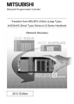
CHAPTER 1
1.1
FEATURES
CC-Link
CC-Link is a system where distributed modules, such as I/O modules and intelligent function modules, are connected
using dedicated cables, enabling a CPU module to control the modules.
Ethernet
Plant level (Information management)
CC-Link IE Controller Network
Among production lines (Production control)
CC-Link IE Field Network
Within a line (Equipment control)
CC-Link
Between a control panel and
equipment
(I/O control of equipment)
(1) High-speed communications
On/off information of I/O signals and values can be smoothly exchanged at high speed. This feature allows the
configuration of a variety of systems.
(2) System with reduced wiring
Because modules can be distributed in large equipment, such as conveyor lines and machines, a system with
reduced wiring can be achieved.
(3) Flexible system design
Various CC-Link devices manufactured by partner vendors are available. Therefore, a system can be flexibly
designed according to application.
(4) Configuration of a distributed system
By connecting multiple programmable controllers to a CC-Link system, a simple distributed system can be
configured. The multiple programmable controllers can perform data link with remote stations and intelligent
device stations and can control distributed devices in a CC-Link system.
16
CHAPTER 1 FEATURES
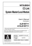
1.2
Master/Local Modules
1
By using master/local modules, MELSEC-Q series programmable controllers can be connected to a CC-Link system.
Remotely-located devices in a CC-Link system can be controlled as if they were on the same base unit as the
master/local module.
The module works as a master station or a local station in CC-Link.
(1) Data communications
(a) Periodic communications (cyclic transmission)
Master/local modules can periodically exchange data with other stations in a CC-Link system. (
Page 125,
Section 8.1.1)
For example, I/O signals of remotely-located stations in a CC-Link system can be used in the same way as
those of the master station.
Terminating
resistor
Master station
CPU module
Master
station
Remote
I/O station
Remote device
station, intelligent
device station
Remote
I/O station
Remote
device station
Terminating
resistor
Local station
Local station
CPU module
X
RX
RX
RX
RY
Y
Y
RY
RY
RY
RX
X
RWw
RWw
RWr
RWr
RWr
RWw
W
1.2 Master/Local Modules
Intelligent
device station
W
(b) Non-periodic communications (transient transmission)
Data can be communicated when a request is issued unlike cyclic transmission.
Direct access to buffer memory areas and devices in other stations can be performed in transient transmission.
(
Page 173, CHAPTER 9)
CPU module
Command
Master station
Local station
CPU module
Instruction
Device
1234H
Terminating
resistor
Write
request
Device
1234H
Terminating
resistor
17
(2) Parameter settings and diagnostics using a programming tool
(a) Parameter settings using a programming tool
Parameters of master/local modules can be set using a programming tool. Therefore, parameter setting
programs need not to be created; resulting in reduction in the program amount. (
Parameters of a master station can be also set using a program. (
Page 93, CHAPTER 7)
Page 205, Section 9.8)
When parameters are set using a program, parameter settings of the master station can be changed without
resetting the CPU module.
18
CHAPTER 1 FEATURES
(b) Diagnostics using a programming tool
The status of a CC-Link system can be checked using a programming tool. Error locations and error causes
are displayed in a programming tool, enabling the user to quickly troubleshoot the problem. (
1
Page 311,
Section 11.4)
Since the master/local module is a CC-Link Ver.2-compatible module, the number of points per system can be
increased up to 8192 for RX/RY and the number of words is up to 2048 for RWr/RWw. On a station basis, the
number of points can be increased up to 896 for RX/RY and the number of words is 128 for RWr/RWw.
A CC-Link Ver.2-compatible system can be larger than a CC-Link Ver.1-compatible system.
Ex. Maximum number of points of the remote input (RX) and remote output (RY)
8192 points
CC-Link Ver.2
CC-Link Ver.1
2048 points
19
1.2 Master/Local Modules
(3) CC-Link Ver.2-compatible module
(4) Prevention of a system failure
(a) Continuation of communications upon module error
• Since a bus topology is employed, communications among normal modules continue even if a module
goes down due to power-off or other causes.
• The equipped two-piece terminal block is removable, enabling module change during data link.*1
Note that if a cable is disconnected, data link fails among all stations.
*1
Power off the module to be replaced before removal. Check that settings of the module that replaces the currently
mounted module are the same as those of the mounted module.
Master station
Error
Terminating
resistor
Terminating
resistor
Data link is continued.
Data link is continued.
(b) Automatic return when a disconnected station recovers
When the station disconnected from a network due to a data link error recovers, it automatically restarts data
link. The time between an error and a return can be shortened.
Master station
Error
Terminating
resistor
Terminating
resistor
Recovering
from the error
Master station
Terminating
resistor
Terminating
resistor
Returned
The master/local module can prevent a system failure by using the following functions as well. (
Page 128, Section 8.2
to Page 154, Section 8.3)
• Even if a master station fails, cyclic transmission can be continued by having the standby master station served as
a master station.
• When a module is replaced, error detection can be temporarily disabled.
20
CHAPTER 2 PART NAMES
CHAPTER 2
PART NAMES
2
This chapter describes the part names of the master/local modules.
No.
Name
RUN LED
Indicates the operating status.
ON
Operating normally
OFF
A hardware failure or a watchdog timer error has occurred.
L RUN LED
Indicates the data link status.
ON
Performing data link
OFF
Not performing data link
MST LED
1)
Application
Indicates whether the module is operating as a master station.
ON
Operating as a master station
OFF
Operating as a local station or a standby master station (in standby status)
S MST LED
ON
OFF
SD LED
Indicates whether the module is operating as a standby master station.
Operating as a standby master station (in standby status)
Operating as a master station or a local station
The LED also turns off when a standby master station switches to a master station.
Indicates whether the module is sending data.
ON
Sending data
OFF
Not sending data
RD LED
Indicates whether the module is receiving data.
ON
Receiving data
OFF
Not receiving data
21
No.
Name
Application
Indicates the error status of the master/local module.
ERR. LED
The details of errors can be checked by using the following.
• CC-Link diagnostics (
Page 311, Section 11.4)
• Detailed LED display status (SW0058) (
Page 351, Appendix 3.2)
Any of the following errors has occurred.
• The error on all the stations was detected.
• The value outside the range is set for the station number setting switches or transmission speed/mode
ON
setting switch of the master/local module.
• Two or more master stations are connected on the same line.
• Settings are incorrect.
• A cable is disconnected. Or a transmission path is affected by noise.
1)
Flashing
OFF
L ERR. LED
ON
Flashing at
regular
intervals
Flashing at
irregular
intervals
OFF
A data link faulty station was detected.
Or the station number set for a remote station is already in use.
Operating normally
Indicates the error status of a data link.
A data link error has occurred at the host station.
The settings of the switches 2) and 3) were changed when the power was on. (Note that the change of the
switch may not be detected at the time of error on all the stations.)
The communications are unstable due to the following reasons.
• A terminating resistor is not connected.
• The communications are affected by noise.
Operating normally
Sets the station number of the master/local module. (Default: 0)
Set the station numbers not used for other stations.
2)
Station number
setting switch
<Setting range>
• Master station: 0
• Local station: 1 to 64
• Standby master station: 1 to 64
If a number other than 0 to 64 is set, the ERR. LED turns on.
22
CHAPTER 2 PART NAMES
No.
Name
Application
Sets the transmission speed and mode of the master/local module. (Default: 0)
Set the same value of the transmission speed for all stations.
Mode
Online
Transmission
3)
speed/mode setting
switch
Line test (
Page 86, Section 6.5.1)
• When the station number setting switches
are set at 0
Line test 1
• When the station number setting switches
are set at 1 to 64
Line test 2
Hardware test (
Page 324, Section 11.5)
Transmission speed
setting
Transmission speed: 156kbps
0
Transmission speed: 625kbps
1
Transmission speed: 2.5Mbps
2
Transmission speed: 5Mbps
3
Transmission speed: 10Mbps
4
Transmission speed: 156kbps
5
Transmission speed: 625kbps
6
Transmission speed: 2.5Mbps
7
Transmission speed: 5Mbps
8
Transmission speed: 10Mbps
9
Transmission speed: 156kbps
A
Transmission speed: 625kbps
B
Transmission speed: 2.5Mbps
C
Transmission speed: 5Mbps
D
Transmission speed: 10Mbps
E
Setting not allowed
Used to connect a CC-Link dedicated cable. (
Switch number
F
Page 77, Section 6.2.2)
The SLD and FG terminals are connected inside the module.
4)
Terminal block
Because a two-piece terminal block is used, the module can be replaced without disconnecting the signal
line to the terminal block.
Before installing or removing the terminal block, power off the module.
5)
Serial number
display
Indicates the serial number on the rating plate.
The settings of the station number setting switches and the transmission speed/mode setting switch are enabled by resetting
the CPU module or powering off and on the system.
23
2
CHAPTER 3
SPECIFICATIONS
This chapter describes the specifications, functions, I/O signals, buffer memory, remote I/O (RX and RY) and remote
register (RWr and RWw) of the master/local module.
3.1
General Specifications
For the general specifications of the master/local module, refer to the following.
User's manual for the CPU module used (hardware design, maintenance and inspection)
3.2
Performance Specifications
Item
Specifications
Transmission speed
Selected from 156kbps, 625kbps, 2.5Mbps, 5Mbps, and 10Mbps.
Maximum number of connected modules
(master station)
Number of occupied stations (local
station)
64 (
Page 27, Section 3.2.1)
1 to 4 stations (The number of stations can be changed using a programming tool.)
• Remote I/O (RX, RY): 2048 points
• Remote register (RWw): 256 points (master station remote device station/local
CC-Link Ver.1
station/intelligent device station/standby master station)
• Remote register (RWr): 256 points (remote device station/local station/intelligent device
station/standby master station master station)
Maximum number of
link points per system
• Remote I/O (RX, RY): 8192 points
• Remote register (RWw): 2048 points (master station remote device station/local
CC-Link Ver.2
station/intelligent device station/standby master station)
• Remote register (RWr): 2048 points (remote device station/local station/intelligent device
station/standby master station master station)
• Remote I/O (RX, RY): 32 points (30 points for a local station)
• Remote register (RWw): 4 points (master station remote device station/local
CC-Link Ver.1
station/intelligent device station/standby master station)
• Remote register (RWr): 4 points (remote device station/local station/intelligent device
station/standby master station master station)
Number of link points
Item
per remote
station/local
station/intelligent
Remote I/O
device station/standby
master station*1
(RX, RY)
CC-Link Ver.2
Expanded Cyclic Setting
Single
Double
Quadruple
Octuple
32 points
32 points
64 points
128 points
(30 points for a
(30 points for a
(62 points for a
(126 points for a
local station)
local station)
local station)
local station)
4 points
8 points
16 points
32 points
4 points
8 points
16 points
32 points
Remote
register
(RWw)
Remote
register (RWr)
24
CHAPTER 3 SPECIFICATIONS
Item
Specifications
Communication method
Broadcast polling method
Synchronization method
Frame synchronization method
Encoding method
NRZI method
Network topology
Bus (RS-485)
Transmission format
HDLC compliant
Error control system
CRC (X16 + X12 + X5 + 1)
3
• Ver.1.10-compatible CC-Link dedicated cable
• CC-Link dedicated cable (Ver.1.00-compatible)
• CC-Link dedicated high-performance cable (Ver.1.00-compatible)
Connection cable
The cables above cannot be used at the same time. If used, normal data transmission is not
guaranteed. In addition, select a terminating resistor to be connected according to the cable
type. (
Page 76, Section 6.2.1 (3))
Maximum overall cable distance
Depends on the transmission speed and CC-Link version. (
(maximum transmission distance)
Page 30, Section 3.2.3)
Page 29, Section 3.2.2,
• Standby master function
• Automatic return function
RAS function
• Slave station cutoff function
• Error detection using link special relays (SBs) and link special registers (SWs)
Number of occupied I/O points
32 points (I/O assignment: intelli 32 points)
Internal current consumption (5VDC)
0.46A
Weight
0.12kg
*1
In CC-Link Ver.1, increasing the number of occupied stations can increase the number of link points per station.
In CC-Link Ver.2, increasing the number of occupied stations and setting the greater value in the expanded cyclic setting
can increase the number of link points per station.
For the points, refer to the following table.
Item
CC-Link Ver.1
Expanded Cyclic Setting
Single
Remote I/O
(RX, RY)
1 station
occupied
register
link points
register
by the
(RWr)
Remote I/O
(RX, RY)
stations
Octuple
32 points
32 points
32 points
64 points
128 points
(30 points for a
(30 points for a
(30 points for a
(62 points for a
(126 points for a
local station)
local station)
local station)
local station)
local station)
4 points
4 points
8 points
16 points
32 points
4 points
4 points
8 points
16 points
32 points
(RWw)
Remote
occupied
Quadruple
Remote
Number of
number of
Double
2
Remote
stations
register
occupied
(RWw)
64 points
64 points
96 points
192 points
384 points
(62 points for a
(62 points for a
(94 points for a
(190 points for a
(382 points for a
local station)
local station)
local station)
local station)
local station)
8 points
8 points
16 points
32 points
64 points
8 points
8 points
16 points
32 points
64 points
Remote
register
(RWr)
25
3.2 Performance Specifications
CC-Link Ver.2
CC-Link Ver.2
Item
CC-Link Ver.1
Expanded Cyclic Setting
Single
Remote I/O
(RX, RY)
3
Remote
stations
register
occupied
(RWw)
Number of
Remote
link points
register
by the
(RWr)
number of
Remote I/O
occupied
(RX, RY)
stations
4
Remote
stations
register
occupied
(RWw)
Double
Quadruple
Octuple
96 points
96 points
160 points
320 points
640 points
(94 points for a
(94 points for a
(158 points for a
(318 points for a
(638 points for a
local station)
local station)
local station)
local station)
local station)
12 points
12 points
24 points
48 points
96 points
12 points
12 points
24 points
48 points
96 points
128 points
128 points
224 points
448 points
896 points
(126 points for a
(126 points for a
(222 points for a
(446 points for a
(894 points for a
local station)
local station)
local station)
local station)
local station)
16 points
16 points
32 points
64 points
128 points
16 points
16 points
32 points
64 points
128 points
Remote
register
(RWr)
26
CHAPTER 3 SPECIFICATIONS
3.2.1
Maximum number of connected modules
A CC-Link system can be configured with the number of modules meeting the following conditions.
1 station in each system
Master station
Maximum of 26 modules
3
Intelligent device station
Local station
CC-Link dedicated cable
Maximum of 42 modules
Maximum of 64 modules
Remote device station
Remote I/O station
(1) Remote net Ver.1 mode
The table below lists the maximum number of connected modules of when a system is configured only with Ver.1compatible slave stations. For the modes, refer to Page 43, Section 3.6.2.
64 modules of a remote I/O station, remote device station, local station, standby master station, and intelligent
device station can be connected in total for one master station. Note, however, that the following conditions must
be satisfied.
Item
Condition 1
Condition 2
{(1 × a) + (2 × b) + (3 × c) + (4 × d)} 64
{(16 × A)+(54 × B)+(88 × C)} 2304
Number of modules
a:
Number of modules occupying one station
b:
Number of modules occupying two stations
c:
Number of modules occupying three stations
d:
Number of modules occupying four stations
A:
Number of remote I/O stations 64
B:
Number of remote device stations 42
C:
Number of local stations, standby master stations, and
intelligent device stations 26
27
3.2 Performance Specifications
3.2.1 Maximum number of connected modules
64 modules in total
(2) Remote net Ver.2 mode and remote net additional mode
The table below lists the maximum number of connected modules of when a system is configured only with Ver.2compatible slave stations. For the modes, refer to Page 43, Section 3.6.2.
64 modules of a remote I/O station, remote device station, local station, standby master station, and intelligent
device station can be connected in total for one master station. Note, however, that the following conditions must
be satisfied.
Item
Condition 1
{(a + a2 + a4+ a8) + (b+ b2 + b4+ b8) × 2 + (c+ c2 + c4 +
c8) × 3 + (d + d2 + d4 + d8) × 4} 64
[{(a × 32) + (a2 × 32) + a4 × 64) + (a8 × 128)} + {(b × 64) +
Condition 2
Number of modules
a:
b:
(b2 × 96) + (b4 × 192) + (b8 × 384)} + {(c × 96) + (c2 ×
160) + (c4 × 320) + (c8 × 640)} + {(d × 128) + (d2 × 224)
+ (d4 × 448) + (d8 × 896)}] 8192
c:
d:
Total number of Ver.1-compatible slave stations occupying one station
and Ver.2-compatible slave stations occupying one station with the
expanded cyclic setting of "Single"
Total number of Ver.1-compatible slave stations occupying two stations
and Ver.2-compatible slave stations occupying two stations with the
expanded cyclic setting of "Single"
Total number of Ver.1-compatible slave stations occupying three
stations and Ver.2-compatible slave stations occupying three stations
with the expanded cyclic setting of "Single"
Total number of Ver.1-compatible slave stations occupying four stations
and Ver.2-compatible slave stations occupying four stations with the
expanded cyclic setting of "Single"
a2: Number of Ver.2-compatible slave stations occupying one station with
the expanded cyclic setting of "Double"
b2: Number of Ver.2-compatible slave stations occupying two stations with
the expanded cyclic setting of "Double"
c2: Number of Ver.2-compatible slave stations occupying three stations
with the expanded cyclic setting of "Double"
d2: Number of Ver.2-compatible slave stations occupying four stations with
the expanded cyclic setting of "Double"
[{(a × 4) + (a2 × 8) + (a4 × 16) + (a8 × 32)} + {(b × 8) + (b2 ×
Condition 3
16) + (b4 × 32) + (b8 × 64)} + {(c × 12) + (c2 × 24) + (c4 × 48)
+ (c8 × 96)}+{(d × 16)+(d2 × 32)+(d4 × 64) + (d8 × 128)}]
2048
a4: Number of Ver.2-compatible slave stations occupying one station with
the expanded cyclic setting of "Quadruple"
b4: Number of Ver.2-compatible slave stations occupying two stations with
the expanded cyclic setting of "Quadruple"
c4: Number of Ver.2-compatible slave stations occupying three stations
with the expanded cyclic setting of "Quadruple"
d4: Number of Ver.2-compatible slave stations occupying four stations with
the expanded cyclic setting of "Quadruple"
a8: Number of Ver.2-compatible slave stations occupying one station with
the expanded cyclic setting of "Octuple"
b8: Number of Ver.2-compatible slave stations occupying two stations with
the expanded cyclic setting of "Octuple"
c8: Number of Ver.2-compatible slave stations occupying three stations
with the expanded cyclic setting of "Octuple"
d8: Number of Ver.2-compatible slave stations occupying four stations with
the expanded cyclic setting of "Octuple"
Condition 4
{(16 × A) + (54 × B) + (88 × C)} 2304
A:
Number of remote I/O stations 64
B:
Number of remote device stations 42
C:
Number of local stations, standby master stations, and intelligent
device stations 26
28
CHAPTER 3 SPECIFICATIONS
3.2.2
Maximum overall cable distance (CC-Link Ver.1.10)
This section describes how transmission speed and a cable length are related when a system is configured with
products of CC-Link Ver.1.10 or later and Ver.1.10-compatible CC-Link dedicated cables. Configure a CC-Link system
that satisfies the following conditions.
Master station
Remote I/O station
or remote
device station
Remote I/O station
or remote
device station
Local station or
intelligent device
station
3
Local station or
intelligent device
station
Station-to-station cable length
Maximum overall cable distance
• Ver.1.10-compatible CC-Link dedicated cable (a terminating resistor of 110 used)
Transmission speed
Station-to-station cable length
Maximum overall cable distance
156kbps
1200m
625kbps
900m
2.5Mbps
20cm or longer
400m
5Mbps
160m
10Mbps
100m
3.2 Performance Specifications
3.2.2 Maximum overall cable distance (CC-Link Ver.1.10)
29
3.2.3
Maximum overall cable distance (CC-Link Ver.1.00)
Configure a CC-Link system where the transmission speed and the cable length satisfy the following conditions.
(1) When a system is configured with a remote I/O station and remote device
station only
Master station
Remote I/O station
or remote
device station
*2
Remote I/O station
or remote
device station
*2
Remote I/O station
or remote
device station
*1
Remote I/O station
or remote
device station
*1
Maximum overall cable distance
• CC-Link dedicated cable (Ver.1.00-compatible) (a terminating resistor of 110 used)
Transmission speed
Station-to-station cable length
*1
*2
156kbps
625kbps
10Mbps
distance
1200m
30cm or longer
600m
2.5Mbps
5Mbps
Maximum overall cable
200m
Between 30cm and 59cm
*3
110m
1m or longer
60cm or longer
150m
Between 30cm and 59cm
*3
50m
Between 60cm and 99cm
*3
80m
1m or longer
100m
• CC-Link dedicated high-performance cable (Ver.1.00-compatible) (a terminating resistor of 130 used)
Transmission speed
Station-to-station cable length
*1
*2
Maximum overall cable
distance
156kbps
1200m
625kbps
900m
2.5Mbps
5Mbps
400m
30cm or longer
160m
Number of
connected stations:
100m
1 to 32
Number of
10Mbps
connected stations:
30
Between 30cm and
80m
40cm or longer
100m
Number of
Between 30cm and 39cm*3
20m
connected stations:
Between 40cm and 69cm*3
30m
70cm or longer
100m
33 to 48
49 to 64
*1
*2
*3
1m or longer
39cm*3
This is a station-to-station cable length between remote I/O stations or remote device stations.
This is a station-to-station cable length between a master station and a station one before/after the master station.
When this range is applied for one section, the maximum overall cable distance is the shortest station-to-station cable
length.
CHAPTER 3 SPECIFICATIONS
Ex. When 43 stations of remote I/O stations and remote device stations are connected using a CC-Link
dedicated high-performance cable (Ver.1.00-compatible)
(Transmission speed: 10Mbps)
Because the cable length between the second station and the third station is 35cm, the maximum overall
cable distance is 80m.
1st
remote I/O station
Master station
1m
50cm
2nd
remote I/O station
3rd
remote I/O station
35cm
4th
remote I/O station
43rd
remote I/O station
3
50cm
3.2 Performance Specifications
3.2.3 Maximum overall cable distance (CC-Link Ver.1.00)
31
(2) When a system is configured with remote I/O stations, remote device stations,
local stations, and intelligent devices stations
Local station
or intelligent
device station
Remote I/O station
or remote
device station
Master station
*2
*2
Remote I/O station
or remote
device station
*1
Local station
or intelligent
device station
*2
Local station
or intelligent
device station
*2
Maximum overall cable distance
• CC-Link dedicated cable (Ver.1.00-compatible) (a terminating resistor of 110 used)
Transmission speed
Station-to-station cable length
*1
*2
156kbps
625kbps
10Mbps
distance
1200m
30cm or longer
600m
2.5Mbps
5Mbps
Maximum overall cable
200m
Between 30cm and 59cm*3
60cm or longer
110m
2m or longer
150m
Between 30cm and 59cm*3
50m
Between 60cm and 99cm*3
80m
1m or longer
100m
• CC-Link dedicated high-performance cable (Ver.1.00-compatible) (a terminating resistor of 130 used)
Transmission speed
Station-to-station cable length
*1
*2
600m
30cm or longer
2.5Mbps
5Mbps
10Mbps
*1
*2
*3
32
distance
1200m
156kbps
625kbps
Maximum overall cable
200m
Between 30cm and 59cm*3
2m or longer
110m
60cm or longer
150m
Between 70cm and 99cm*3
50m
1m or longer
80m
This is a station-to-station cable length between remote I/O stations or remote device stations.
This is a station-to-station cable length between a master station and a station one before/after the master station, a
local station and a station one before/after the local station, or an intelligent device station and a station one before/after
the intelligent device station.
When this range is applied for one section, the maximum overall cable distance is the shortest station-to-station cable
length.
CHAPTER 3 SPECIFICATIONS
3.2.4
CC-Link dedicated cables
In a CC-Link system, use CC-Link dedicated cables. If cables other than CC-Link dedicated cables are used, the
performance of the CC-Link system is not guaranteed.
For the specifications of CC-Link dedicated cables and contact information, refer to the following.
3
Website of CC-Link Partner Association: www.cc-link.org
Remark
Refer to the CC-Link Cable Wiring Manual published by CC-Link Partner Association.
3.2 Performance Specifications
3.2.4 CC-Link dedicated cables
33
3.3
List of Functions
(1) Cyclic transmission
Function
Description
Reference
Communications can be performed with other stations using
remote I/O (RX, RY) and remote registers (RWr, RWw).
Communications with other stations
Access to remote slave stations can be performed in the same
way as access to a module mounted on the same base unit is
Page 41, Section 3.6.1
Page 125, Section 8.1.1
performed.
Remote net Ver.1 mode
The mode can be selected according to the CC-Link system
Page 46, Section 3.6.3
Remote net Ver.2 mode
configuration. There is a mode such as the one to add a Ver.2-
Page 48, Section 3.6.4
Remote net additional mode
compatible slave station to a system with a Ver.1-compatible
Page 51, Section 3.6.5
Remote I/O net mode
slave station.
Page 55, Section 3.6.6
Data can be automatically transferred between RX, RY, RWr,
RWw, SB, and SW in a master/local module and a device in a
Auto refresh
CPU module.
Accessing a device in a CPU module on a program enables
Page 97, Section 7.3.2
Page 115, Section 7.4.2
access to RX, RY, RWr, RWw, SB, and SW.
Whether to synchronize the link scan with the sequence scan of
a CPU module or not can be selected.
Scan synchronization
Selecting the asynchronous setting shortens input transmission
Page 163, Section 8.3.5
delay time. Selecting the synchronous setting shortens output
transmission delay time.
Cyclic data assurance
This function prevents read/write data from being separated
between new and old data.
-
This function prevents read/write data per station from being
separated between new and old data depending on the auto
Block data assurance per station
refresh timing. Because the setting is configured only on a
programming tool, a program to prevent data separation is not
Page 150, Section 8.2.6
(1)
required.
32-bit data integrity assurance
This function prevents read/write data in 32-bit increments from
being separated between new and old data.
Page 153, Section 8.2.6
(2)
Data link of the host station can be stopped or restarted using a
Data link stop/restart
programming tool or SB/SW. This function is used when data
Page 169, Section 8.3.8
link should be temporarily stopped for maintenance or other
Page 320, Section 11.4.5
reasons.
When the master station is in the remote net Ver.2 mode, the
refresh points with a remote I/O station can be selected from 8
Remote I/O station points setting
points, 16 points, and 32 points. Changing the number of points
can save the areas of the refresh device in a CPU module. (In
Page 170, Section 8.3.9
modes other than the remote net Ver.2 mode, only 32 points per
station can be selected.)
(2) Transient transmission
Function
Description
Reference
Communications can be performed with other stations at any
Communications using a dedicated
instruction
timing.
Unlike cyclic transmission, direct access to buffer memory areas
in other stations can be performed. This function is used to
access data that is updated infrequently.
34
Page 127, Section 8.1.2
Page 173, CHAPTER 9
CHAPTER 3 SPECIFICATIONS
(3) RAS function
Function
Description
Reference
Data link can be continued in a normal station by disconnecting
a slave station that cannot perform data link due to reasons
Slave station cutoff function
such as power-off. (No parameter setting is required.)
Page 128, Section 8.2.1
3
Using this function prevents the entire system from going down
when one station goes down.
When a slave station that has been disconnected from data link
Automatic return function
due to reasons such as power-off returns to the normal status,
data link is automatically restarted. The time between an error
Page 128, Section 8.2.1
and a return can be shortened.
Setting of the data link status upon an error
in the programmable controller CPU of the
master station
Setting of the status of the input data from a
data link faulty station
Slave station refresh/compulsory clear
setting in case of programmable controller
CPU STOP
Whether to stop or continue data link when a stop error occurs
in the CPU module of a master station can be selected.
Page 130, Section 8.2.2
Whether to clear or hold data input from a data link faulty station
can be selected. How data should be handled can be selected
Page 131, Section 8.2.3
according to the system used.
Whether to refresh or compulsorily clear remote output (RY)
when the switch on a CPU module is set to STOP can be
selected. How data should be handled can be selected
Page 133, Section 8.2.4
according to the system used.
If the master station goes down due to an error in a CPU
module, power supply, or others, switching the control to the
Standby master function
standby master station (a backup station for the master station)
Page 135, Section 8.2.5
continues data link. This function is used not to stop the entire
system even if the master station goes down.
function
Even if a master station duplication error has been detected, the
error can be cleared without resetting the CPU module or
Page 172, Section 8.3.10
powering off and on the system.
(4) Diagnostics function
Function
Line test
Description
Whether a CC-Link dedicated cable is properly connected and
data link can be performed with slave stations can be checked.
Reference
Page 86, Section 6.5.1
Whether the transmission speed setting of a slave station is the
same as that of the master station can be checked. The station
Transmission speed test
number of the slave station having a different transmission
Page 90, Section 6.5.2
speed setting can be also checked; therefore, corrective actions
upon a transmission error can be easily taken.
The status of a CC-Link system can be checked using a
programming tool. Unlike link special relays (SBs) and link
CC-Link diagnostics
special registers (SWs), the system status can be checked on a
Page 311, Section 11.4
graphical window; therefore, corrective actions can be easily
taken.
Hardware test
The hardware in the master/local module can be checked.
Page 324, Section 11.5
35
3.3 List of Functions
Master station duplication error canceling
(5) Other functions
Function
Description
Reference
The initial setting of a remote device station that was performed
Remote device station initialization
procedure registration function
on a program can be registered in advance using a
programmable controller and can be saved by turning on the
Page 154, Section 8.3.1
link special relay (SB). A program for the initial setting is not
required.
A request for the interrupt to a CPU module is issued when the
conditions that have been set using a programming tool are
Event issuance for the interrupt program
satisfied, and the interrupt program can be executed. This
Page 158, Section 8.3.2
function is used to stop the control and execute an interrupt
program upon an error or for other purposes.
Data link can be performed by powering on the master/local
Automatic CC-Link startup
module. This function is used to check the operation of when a
Page 159, Section 8.3.3
system is configured.
Slave stations that are not actually connected (but will be
connected in future) are not detected as "Data Link Faulty
Station" in the master station and local station.
By setting slave stations that will be connected in future as
Reserved station function
reserved stations, slave stations can be added without a
Page 162, Section 8.3.4
program change because the RX/RY/RWr/RWw assignment is
not changed. In addition, the number of points of a slave station
that has been set as a reserved station can be set as zero
points.
Even if a data link error occurs in a slave station, the station is
Error invalid station setting function
not detected as a faulty station in the master station and local
station. This function is used when a slave station is powered off
Page 167, Section 8.3.6
as a matter of the system configuration or for other purposes.
Even if a data link error occurs in a slave station, the station is
not detected as a faulty station in the master station and local
Temporary error invalid station setting
station. This setting can be configured even during data link,
function
unlike the error invalid station setting function.
Page 168, Section 8.3.7
This function is used to exchange slave stations during data link
for maintenance or for other purposes.
The time of setting parameters can be reduced by automatically
Automatic detection of connected devices
reading information of slave stations.
The model names of slave stations can be read.
Page 102, Section 7.3.2 (2)
iQ Sensor Solution
Reference Manual
The setting data of the slave station is backed up into the SD
Data backup/restoration
memory card of the CPU module on the master station.
The setting data backed up on the SD memory card of the CPU
module on the master station is restored into the slave module.
36
iQ Sensor Solution
Reference Manual
CHAPTER 3 SPECIFICATIONS
3.4
List of I/O signals
This section lists the I/O signals for a CPU module.
The device X is an input signal from a master/local module to a CPU module. The device Y is an output signal from a
CPU module to a master/local module.
"n" in the table below represents the start I/O number of the master/local module.
3
Ex. When the start I/O number of the master/local module is 0030:
Xn0 to X(n + 1)F X30 to X4F
Yn0 to Y(n + 1)F Y30 to Y4F
Signal direction: Master/local module CPU module
Signal direction: CPU module Master/local module
Input No.
Signal name
Output No.
Xn0
Module error
Yn0
Xn1
Host data link status
Yn1
Xn2
Use prohibited
Yn2
Xn3
Other station data link status
Yn3
Xn4
Yn4
Xn5
Yn5
Xn6
Yn6
Xn7
Yn7
Xn8
Yn8
Xn9
Use prohibited
XnA
Yn9
YnA
YnB
YnC
XnD
YnD
XnE
YnE
Module ready
YnF
X(n+1)0
Y(n+1)0
X(n+1)1
Y(n+1)1
X(n+1)2
Y(n+1)2
X(n+1)3
Y(n+1)3
X(n+1)4
Y(n+1)4
X(n+1)5
Y(n+1)5
X(n+1)6
Y(n+1)6
X(n+1)7
X(n+1)8
3.4 List of I/O signals
XnB
XnC
XnF
Signal name
Use prohibited
Use prohibited
Y(n+1)7
Y(n+1)8
X(n+1)9
Y(n+1)9
X(n+1)A
Y(n+1)A
X(n+1)B
Y(n+1)B
X(n+1)D
Y(n+1)D
X(n+1)D
Y(n+1)D
X(n+1)E
Y(n+1)E
X(n+1)F
Y(n+1)F
● Do not turn on the “Use prohibited” signals of the I/O signals for the CPU module.
Doing so may cause a malfunction in the programmable controller system.
37
3.5
List of Buffer Memory Areas
Buffer memory is memory to transmit data between a master/local module and a CPU module.
Data can be read from or written to buffer memory areas by setting the parameters of a programming tool or using
dedicated instructions.
Resetting the CPU module or powering off and on the system returns data in buffer memory areas to default.
When a standby master station is used, refer to the respective columns under "Availability" in the table as explained
below.
• When a standby master station is operating as a master station: "Master station" column
• When a standby master station is operating as a standby master station: "Local station" column
: Can be used, –: Cannot be used
Address
Hexadecimal
Availability
Name
Decimal
Description
Read/write
Master
Local
station
station
Reference
(Not available
Parameter
0 to DFH
0 to 223
information
Page 328,
when a
Stores parameter settings.
Read only
area
standby master
–
Appendix 2
(1)
station is
controlling the
system)
(Master station)
Stores the status of the data
E0H to 15FH
224 to
Remote input
351
(RX)*1
–
input from slave stations.
(Local station)
Page 331,
Read only
Stores the status of the data
Appendix 2
(2)
–
input from the master
station.
(Master station)
Stores the status of the data
Write only
–
output to slave stations.
(Local station)
160H to 1DFH
352 to
Remote output
479
(RY)*1
Page 331,
Stores the status of the data
Appendix 2
output to the master station.
Stores the status of the data
Read/
output to slave stations.
write
(2)
–
Data received from other
slave stations are also
stored.
Remote register
(Master station)
(RWw)*1
Stores the send data to
• Master
1E0H to 2DFH
38
480 to
735
Write only
–
slave stations.
station: For
(Local station)
Page 333,
data sending
Stores the send data to the
Appendix 2
• Local station:
master station and other
Read/
For data
salve stations. Data
write
sending/
received from other slave
receiving
stations are also stored.
–
(3)
CHAPTER 3 SPECIFICATIONS
Address
Hexadecimal
Decimal
Availability
Name
Remote register
(Master station)
(RWr)*1
Stores the data received
• Master
2E0H to 3DFH
736 to
991
Description
Read/write
Master
Local
station
station
-
from slave stations.
Page 333,
station: For
data
receiving
• Local station:
For data
Reference
(Local station)
Read only
Stores the data received
Appendix 2
(3)
-
3
from the master station.
receiving
3E0H to 5DFH
5E0H to 5FFH
992 to
1503
Slave station
Stores the offset and size of
offset, size
RX/RY/RWw/RWr in each
information
slave station.
1504 to
Link special
1535
relay (SB)
Page 335,
Read only
Appendix 2
(4)
Stores the data link status.
Read/
Page 338,
write
Appendix 2
(5)
(Data can be
written only
600H to 7FFH
1536 to
Link special
2047
register (SW)
Stores the data link status.
Page 339,
to areas with
Appendix 2
the first 32
(6)
addresses.)
800H to 9FFH
A00H to FFFH
2048 to
2559
System area
-
-
2560 to
Random access
Stores any data and is used
Read/
4095
buffer
for transient transmission.
write
-
-
Page 339,
Appendix 2
(7)
Stores sending/receiving
transient transmission
1000H to 1FFFH
4096 to
Communication
8191
buffer
(communications using a
communication buffer) is
performed with a local
Page 339,
Read/
Appendix 2
write
(8)
station, standby master
station, and intelligent
device station.
Stores data automatically
updated when transient
2000H to 2FFFH
8192 to
Automatic
12287
update buffer
transmission
(communications using the
automatic update buffer) is
Page 340,
Read/
-
write
Appendix 2
(9)
performed with an AJ65BTR2(N).
3000H to 3FFFH
12288 to
16383
System area
-
-
-
-
-
(Master station)
Ver.24000H to 41FFH
16384 to
compatible
16895
remote input
(RX)*2
Stores the status of the data
-
input from slave stations.
(Local station)
Stores the status of the data
input from the master
Page 341,
Read only
Appendix 2
-
(10)
station.
39
3.5 List of Buffer Memory Areas
data and control data when
Address
Hexadecimal
Availability
Decimal
Name
Description
Read/write
Master
Local
station
station
Reference
(Master station)
Stores the status of the data
Ver.24200H to 43FFH
16896 to
compatible
17407
remote output
(RY)*2
Write only
-
output to slave stations.
Page 341,
(Local station)
Appendix 2
Stores the status of the data
output to the master station.
Read/
Data received from other
write
(10)
-
slave stations are also
stored.
Ver.2-
(Master station)
compatible
Stores the send data to
remote register
slave stations.
Write only
-
(RWw)*2
4400H to
17408 to
4BFFH
19455
• Master
Page 342,
(Local station)
Appendix 2
station: For
Stores the send data to the
data sending
master station and other
Read/
salve stations. Data
write
• Local station:
For data
received from other slave
sending/
stations are also stored.
(11)
-
receiving
Ver.2-
(Master station)
compatible
Stores the data received
remote register
from slave stations.
-
(RWr)*2
4C00H to
19456 to
53FFH
21503
Page 342,
• Master
station: For
data
receiving
• Local station:
(Local station)
Read only
Stores the data received
Appendix 2
(11)
-
from the master station.
For data
receiving
5400H to 7FFFH
*1
*2
21504 to
32767
System area
-
-
-
-
This buffer memory area is used when the remote net Ver.1 mode and remote net additional mode are selected.
This buffer memory area is used when the remote net Ver.2 mode and remote net additional mode are selected.
Do not write data to "System area".
Doing so may cause malfunction in the programmable controller system.
40
-
CHAPTER 3 SPECIFICATIONS
3.6
Assignment and Modes
For a master/local module, the mode can be selected according to the system used. For example, there is a mode to
configure a new system or a mode to add a Ver.2-compatible slave station to a Ver.1-compatible slave station.
Depending on the mode, the addresses of buffer memory areas to store RX, RY, RWr, and RWw vary.
3.6.1
3
Assignment
In CC-Link, communications are performed between the master station and slave stations using RX, RY, RWr, and
RWw. Data in RX, RY, RWr, and RWw of the master/local module are stored in the buffer memory.
This section describes the assignment using an example of data input and output of the master station and local
station.
CPU
module
Master
station
Station No.0
Remote I/O station*1
Remote device station
Intelligent device station
Station No.1
Station No.2
Buffer
memory
Device
Local station
Station No.3
Buffer
memory
RX, RWr
Station
No.1
Range of the
station No.1
sending data
Device
RX, RWr
Station
No.2
RX, RWr
Station
No.1
Range of the
station No.2
sending data
Station
No.2
Station
No.3
3.6 Assignment and Modes
3.6.1 Assignment
RX, RWr
CPU
module
Station
No.3
RY, RWw
RY, RWw
Range of the
master station
sending data to
the station No.1
Station
No.1
RY, RWw
Range of the
master station
sending data to
the station No.2
RY, RWw
Station
No.1
Station
No.2
Station
No.2
Range of the
master station
sending data to
the station No.3
Range of the
station No.3
sending data
Data sent from the master station
Area where data is sent to other
stations
Data sent from slave stations
*1
RWr and RWw are not used for a remote I/O station. Note, however, that buffer memory areas are occupied depending
on the mode of the master/local module. (
Page 46, Section 3.6.3 to Page 55, Section 3.6.6)
● Buffer memory (RX, RY, RWr, and RWw) addresses differ depending on the mode of the master/local module.
(
Page 46, Section 3.6.3 to Page 55, Section 3.6.6)
● In a local station, data in RX and RWr of other slave stations are stored into RY and RWw, and data in RY and RWw of
other stations are stored into RX and RWr. (Areas where data is input and output are reversed.)
41
(1) Input and output of the master station
Data can be input to and output from all slave stations. Areas are assigned in the order of station number.
(a) Data input to the master station
Data in RX and RWr of all slave stations are stored into RX and RWr of the master station.
In a local station, however, data in RY and RWw of a local station are stored into RX and RWr of the master
station.
(b) Data output from the master station
Data stored in RY and RWw of the master station are output to RY and RWw of all slave stations.
In a local station, however, data are stored into RX and RWr.
(2) Input and output of a local station
Data can be input from all slave stations. Data can be output from a local station only to the master station.
Areas are assigned in the order of station number.
(a) Data input to a local station
Data in RY and RWw of other stations are stored into RX and RWr of a local station.
Data in RX and RWr of other slave stations are stored into RY and RWw of local stations.
(b) Data output from a local station
Data stored in RY and RWw (the area in the host station for data sending) are stored into RX and RWr of the
master station.
42
CHAPTER 3 SPECIFICATIONS
3.6.2
Modes
This section describes the modes of a master/local module.
(1) List of modes
Select the mode according to the system used.
Mode
Application
Remote net Ver.1
• To configure a new system (only with Ver.1-compatible slave
mode
stations)
• To configure a system including a Ver.2-compatible slave
Remote net Ver.2
station
mode
• More points are used compared to the remote net Ver.1 mode.
Remote net additional
mode
• To add a Ver.2-compatible slave station to an existing Ver.1
system (using the program of the Ver.1 system)
Remote I/O net mode*1
*1
• To configure a system only with remote I/O stations
3
Connectable
slave station
Ver.1-compatible
slave station
Ver.1-compatible
slave station and
Reference
Page 46, Section 3.6.3
Page 48, Section 3.6.4
Ver.2-compatible
slave station
Page 51, Section 3.6.5
Remote I/O station
Page 55, Section 3.6.6
This mode cannot be selected for a local station.
3.6 Assignment and Modes
3.6.2 Modes
43
(a) Combination of the modes of a master/local module
The table below lists the combination of the modes of the master station and local station in a master/local
module.
: Data link can be performed. ×: Data link cannot be performed.
Mode of a local station*1
Mode of the master station
Remote net Ver.1
Remote net Ver.2
Remote net additional
mode
mode
mode
Remote net Ver.1 mode
×
Remote net Ver.2 mode
*2
Remote net additional mode
*2
*1
*2
×
In a standby master station, data link can be performed only when the mode is the same as that of the master station.
Although a local station in the remote net Ver.1 mode cannot perform data link with a Ver.2-compatible slave station, the
status of the Ver.2-compatible slave station is stored in Other station data link status (SW0080 to SW0083) for the local
station as well as that for the master station. (When the master station is normally performing data link with the Ver.2compatible slave station, Other station data link status (SW0080 to SW0083) for the local station indicates "0: Normal".)
Note that cyclic data in the Ver.2-compatible slave station will become "0" in the local station in the remote net Ver.1
mode. Transient transmission cannot be performed due to an error such as a timeout error.
Master station
Ver.2 mode
Local station Ver.2 mode
(Station No.1, the number
of occupied stations: 1)
Local station Ver.1 mode
(Station No.2, the number
of occupied stations: 1)
Remote device station
Remote device station
Ver.2-compatible
Ver.1-compatible
(Station No.3, the number (Station No.4, the number
of occupied stations: 1)
of occupied stations: 1)
Ver.1-compatible
remote input (RX)
Station No.1
Station No.2
Station No.3
Station No.4
Ver.2-compatible
remote output (RY)
Ver.2-compatible
remote input (RX)
Station No.1
Station No.2
Station No.3
Station No.4
Station No.1
Station No.2
Station No.3
Station No.4
All 0
Remote output (RY)
Remote output (RY)
Data for the station numbers 1 and 3
in the Ver.2-compatible slave station is 0.
(b) Differences in functions between the modes of a master/local module
The following table lists differences in functions between the modes of a master/local module.
Mode of a master/local module
Item
Remote net Ver.1
mode, remote I/O
Remote net Ver.2
Remote net additional
mode
mode
net mode
Ver.1 compatible station:
Storage area for RX/RY/RWr/RWw
Ver.1 compatible area
Ver.2 compatible area
Ver.1-compatible area
Ver.2 compatible station:
Ver.2-compatible area
RWr/RWw of remote I/O stations
Zero points setting for a reserved
station
Remote I/O station points setting
*1
44
4 points per station*1
0 point (RWr and RWw
move over forward.)
4 points per station
Not available
Available
Not available
Not available
Available
Not available
RWr and RWw are not used for the remote I/O net mode.
CHAPTER 3 SPECIFICATIONS
(2) How to set the mode
Set the mode using the network parameter. (
Page 97, Section 7.3.2, Page 115, Section 7.4.2, Page 213,
Section 9.8.1)
3
3.6 Assignment and Modes
3.6.2 Modes
45
3.6.3
Remote net Ver.1 mode
This mode is selected when a new CC-Link system is configured. When the system includes a Ver.2-compatible slave
station, select the remote net Ver.2 mode. (
Master station
(Remote net Ver.1 mode)
Station No.0
Ver.1-compatible
area
Page 48, Section 3.6.4)
Remote device station
Intelligent device station
(Ver.1-compatible)
Station No.1
RX
RX
Station
No.1
Range of
the station
No.1
sending data
RY
Range of
the station
No.2
sending data
RY
Ver.1-compatible
area
Station
No.1
Station
No.2
RY
Station
No.1
Station
No.2
Station
No.2
Range of the
station No.3
sending data
RWr
RWr
Station
No.1
Range of
the station
No.1
sending data
*1
RWr
Station
No.1
Station
No.2
Station
No.2
Station
No.3
Station
No.3
RWw
*1
RY
Station
No.1
Range of the master
station sending data to
the station No.3
Range of the master
station sending data to
the station No.1
*2
Station No.3
Station
No.3
Range of the master
station sending data to
the station No.2
*2
RX
Station
No.3
Range of the master
station sending data to
the station No.1
*1
Station No.2
Local station
(Remote net Ver.1 mode)
RX
Station
No.2
*1
Remote I/O station
(Ver.1-compatible)
RWw
RWw
Station
No.1
Station
No.1
Station
No.2
Station
No.2
Range of the master
station sending data to
the station No.3
Range of the
station No.3
sending data
Data sent from the master station
*2
*2
Area where data is sent to
other stations
Data sent from slave stations
*1
*2
The last two bits in RX and RY cannot be used for communications between a master station and a local station.
A remote I/O station does not have RWr or RWw. However, areas in RWr and RWw of the master station and a local
station are occupied for the number of points of a remote I/O station. When areas in RWr and RWw should not be
occupied, use the remote net Ver.2 mode. (
46
Page 48, Section 3.6.4)
CHAPTER 3 SPECIFICATIONS
(1) Points per module and per system
For the points, refer to the table of the performance specifications. (
Page 24, Section 3.2)
In CC-Link, increasing the number of occupied stations can increase the number of points per module. The
number of occupied stations is set for each slave station. (
Page 102, Section 7.3.2 (2), Page 118, Section
7.4.2 (1))
Item
3
Description
The number of points is increased by increasing the station numbers
occupied per module.
Number of Occupied Stations
Note that the number of slave stations that can be connected to a CCLink system is decreased because one module occupies the station
numbers for multiple modules.
(2) Data transfer between RX, RY, RWr, and RWw and a device in a CPU module
(a) Automatic transfer by parameter settings using a programming tool
Setting a refresh device using the network parameter can automatically transfer data between RX, RY, RWr,
and RWw in a master/local module and a device in a CPU module. (
Page 97, Section 7.3.2, Page 115,
Section 7.4.2)
3.6 Assignment and Modes
3.6.3 Remote net Ver.1 mode
(b) Transfer using a program
Using an intelligent function module device (Un\G) and FROM/TO instructions transfers data between the
buffer memory areas in a master/local module and a device in a CPU module. Use this function to use a
different refresh device for each station or for other purposes.
Address
Hexadecimal
Item
Decimal
E0H to 15FH
224 to 351
Remote input (RX)
160H to 1DFH
352 to 479
Remote output (RY)
1E0H to 2DFH
480 to 735
Remote register (RWw)
2E0H to 3DFH
736 to 991
Remote register (RWr)
Reference
Page 331, Appendix 2 (2)
Page 333, Appendix 2 (3)
(3) Storage locations of RX, RY, RWr, and RWw
Areas are assigned by 32 points in the order of station number to the remote input (RX) and remote output (RY).
To the remote register (RWr and RWw), areas are assigned by four points in the order of station number.
(
Page 331, Appendix 2 (2), Page 333, Appendix 2 (3))
47
3.6.4
Remote net Ver.2 mode
This mode is selected when a new CC-Link system including a Ver.2-compatible slave station is configured.
More points can be used compared to the remote net Ver.1 mode. (
Master station
(Remote net Ver.2 mode)
Station No.0
Ver.2-compatible
area
Remote device station
Intelligent device station
Remote I/O station
(Ver.1- or Ver.2-compatible) (Ver.1-compatible)
Station No.1
RX
RX
Station
No.1
Range of
the station
No.1
sending data
RX
Range of
the station
No.2
sending data
Station
No.3
RY
Range of the master
station sending data to
the station No.1
RY
Station
No.1
Station
No.2
Station
No.1
RY
Station
No.1
Station
No.2
Station
No.2
Range of the
station No.3
sending data
RWr
RWr
RWr
Station
No.1
Range of
the station
No.1
sending data
Station
No.1
RWw
*1
*1
*2
Station
No.3
Station
No.3
Range of the master
station sending data to
the station No.1
Ver.1- or
Ver.2-compatible
*3
area
RY
Range of the master
station sending data to
the station No.3
*2
*2
Station No.3
Station
No.3
Range of the master
station sending data to
the station No.2
*1
Station No.2
Local station
(Remote net Ver.1 mode
or remote net Ver.2 mode)
RX
Station
No.2
*1
Page 24, Section 3.2)
RWw
RWw
Station
No.1
Station
No.1
Range of the
station No.3
sending data
Range of the master
station sending data to
the station No.3
Data sent from the master station
*2
Area where data is sent to
other stations
Data sent from slave stations
*1
*2
*3
48
The last two bits in RX and RY cannot be used for communications between a master station and a local station.
In the master station and a local station, 0 points are assigned to RWr and RWw in a remote I/O station. (Buffer memory
areas move over.)
Note that buffer memory areas for RWr and RWw in a local station do not move over when the local station is in the
remote net Ver.1 mode.
When a local station is in the remote net Ver.1 mode, data are stored in the Ver.1-compatible area. When a local station
is in the remote net Ver.2 mode, data are stored in the Ver.2-compatible area.
CHAPTER 3 SPECIFICATIONS
(1) Points per module and per system
For the points, refer to the table of the performance specifications. (
Page 24, Section 3.2)
In CC-Link, increasing the number of occupied stations and expanded cyclic setting can increase points per
module. Set the number of occupied stations and expanded cyclic setting for each slave station. (
Page 102,
Section 7.3.2 (2), Page 118, Section 7.4.2 (1))
Item
3
Description
The number of points is increased by increasing the station numbers
occupied per module.
Number of Occupied Stations
Note that the number of slave stations that can be connected to a CCLink system is decreased because one module occupies the station
numbers for multiple modules.
The station numbers occupied by one module are not changed, and only
the number of points is increased.
Expanded Cyclic Setting (CC-Link Ver.2 only)
Unlike "Number of Occupied Stations", the number of slave stations
connected to a CC-Link system is not decreased. Note, however, that
the transmission delay time is extended compared to that of when the
number of points is increased in "Number of Occupied Stations".
(2) Data transfer between RX, RY, RWr, and RWw and a device in a CPU module
(a) Automatic transfer by parameter settings using a programming tool
Setting a refresh device using the network parameter can automatically transfer data between RX, RY, RWr,
and RWw in a master/local module and a device in a CPU module. (
Page 97, Section 7.3.2, Page 115,
Section 7.4.2)
3.6 Assignment and Modes
3.6.4 Remote net Ver.2 mode
(b) Transfer using a program
Using an intelligent function module device (Un\G) and FROM/TO instructions transfers data between the
buffer memory areas in a master/local module and a device in a CPU module. Use this function to use a
different refresh device for each station or for other purposes.
Address
Hexadecimal
Decimal
Item
Reference
4000H to 41FFH
16384 to 16895
Ver.2-compatible remote input (RX)
Page 341, Appendix 2
4200H to 43FFH
16896 to 17407
Ver.2-compatible remote output (RY)
(10)
4400H to 4BFFH
17408 to 19455
Ver.2-compatible remote register (RWw)
Page 342, Appendix 2
4C00H to 53FFH
19456 to 21503
Ver.2-compatible remote register (RWr)
(11)
49
(3) Storage locations of RX, RY, RWr, and RWw
The storage locations change depending on the number of occupied stations and expanded cyclic setting in slave
stations. The storage locations for each station can be checked using Slave station offset, size information
(Un\G992 to Un\G1503). (
Page 335, Appendix 2 (4))
● Local station
Data stored in RX, RY, RWr, and RWw in the local station side are stored in a remote net Ver.1 mode area when the
master station is in the remote net Ver.2 mode and the local station is in the remote net Ver.1 mode. (
Page 47,
Section 3.6.3 (2))
Four points are occupied per station for RWr and RWr in a remote I/O station. (Buffer memory areas do not move over.)
(4) Precautions
(a) When changed from the remote net Ver.1 mode
In the remote net Ver.2 mode, zero points are assigned to RWr and RWw in a remote I/O station. (Buffer
memory areas move over.)
The assignment of the station numbers for stations after the remote I/O station changes; therefore, change the
program if required.
50
CHAPTER 3 SPECIFICATIONS
3.6.5
Remote net additional mode
This mode is selected when a Ver.2-compatible slave station is added to an existing Ver.1 system and cyclic points are
expanded. Unlike the remote net Ver.2 mode, RX, RY, RWr, and RWw in a Ver.1-compatible slave station are stored
into buffer memory for the Ver.1 (same buffer memory addresses); therefore, a program in the remote net Ver.1 mode
can be used.
Remote device station
Intelligent device station Remote I/O station
Master station
(Ver.1-compatible)
(Remote net additional mode)
(Ver.1-compatible)
Station No.0
Station No.1
Station No.2
RX
RX
RX
Station
No.1
Station
No.2
Range of
the station
No.1
sending data
Ver.1-compatible
area
RY
Range of the master
station sending data to
the station No.1
Range of the master
station sending data to
the station No.2
*1
RX Ver.1-compatible
area
Station
No.1
Range of
the station
No.2
sending data
Station
No.2
RY
RY
Station
No.1
Station
No.1
Station
No.2
RY
Station
No.2
RWr
Station
No.1
Station
No.2
Station
No.2
RWw
RWw
Station
No.1
Station
No.1
Station
No.2
Station No.2
RX
Station
No.3
Station
No.4
RY
Range of the master
station sending data to
the station No.3
Range of the master
station sending data to
the station No.4
RWr
Station
No.3
Station
No.4
RWw
Range of the master
station sending data to
the station No.3
Range of the master
station sending data to
the station No.4
RX
Range of
the station
No.3
sending data
RY
Station
No.3
Station
No.3
Range of the
station No.4
sending data
Range of
the station
No.3
sending data
*1
RX Ver.2-compatible
Station
No.3
Station
No.4
RY
RWr
*1
3.6 Assignment and Modes
3.6.5 Remote net additional mode
RWr
Range of
the station
No.1
sending data
Ver.2-compatible
area
*2
Station No.4
RWr
RWw
*2
Station No.3
3
Local station
(Remote net additional mode)
Station
No.1
Range of the master
station sending data to
the station No.1
*1
Remote device station
Intelligent device station
(Ver.2-compatible)
area
*2
*2
RWr
Station
No.3
Station
No.4
RWw
RWw
Station
No.3
Station
No.3
Range of
the station No.4
sending data
Data sent from the master station
Area where data is sent to
other stations
Data sent from slave stations
51
*1
Areas in RWr and RWw are occupied for the number of points of the remote I/O station in the master station and local
*2
station. When areas in RWr and RWw should not be occupied, use the remote net Ver.2 mode. (
Page 48, Section
3.6.4)
The last two bits in RX and RY cannot be used for communications between a master station and a local station.
● The assignment of RX, RY, RWr, and RWw in a Ver.1-compatible slave station is the same as that in the remote net Ver.1
mode; therefore, a program that has been used in the remote net Ver.1 mode can be used.
• Buffer memory addresses where RX, RY, RWr, and RWw are stored are Ver.1-compatible areas.
• A remote I/O station does not have RWr or RWw. However, areas in RWr and RWw of the master station and a
local station are occupied for the number of points of a remote I/O station.
● In the remote net additional mode, add a Ver.2-compatible slave station (including a local station in the remote net
additional mode) to a station number after a Ver.1-compatible slave station. When there is a possibility to add a Ver.1compatible slave station in future, set a reserved station at the end of the Ver.1-compatible slave station.
To add a station number of a Ver.2-compatible slave station between station numbers of a Ver.1-compatible slave station,
use the remote net Ver.2 mode.
● In a system where a standby master station is used, changing the mode to the remote net Ver.2 mode is recommended.
In the remote net additional mode, the storage locations of RX, RY, RWr, and RWw differ between a Ver.1-compatible
slave station and a Ver.2-compatible slave station; therefore, changing a program for a standby master station is
required.
(1) Points per module and per system
For the points, refer to the table of the performance specifications. (
Page 24, Section 3.2)
In CC-Link, increasing the number of occupied stations and setting the greater value in the expanded cyclic
setting can increase the number of points. Set the number of occupied stations and expanded cyclic setting for
each slave station. (
Page 102, Section 7.3.2 (2), Page 118, Section 7.4.2 (1))
Item
Description
The number of points is increased by increasing the station numbers
occupied per module.
Number of Occupied Stations
Note that the number of slave stations that can be connected to a CCLink system is decreased because one module occupies the station
numbers for multiple modules.
The station numbers occupied by one module are not changed, and only
the number of points is increased.
Expanded Cyclic Setting (CC-Link Ver.2 only)
Unlike "Number of Occupied Stations", the number of slave stations
connected to a CC-Link system is not decreased. Note, however, that
the transmission delay time is extended compared to that of when the
number of points is increased in "Number of Occupied Stations".
52
CHAPTER 3 SPECIFICATIONS
(2) Data transfer between RX, RY, RWr, and RWw and a device in a CPU module
In the remote net additional mode, data of a Ver.1-compatible slave station are stored into a Ver.1-compatible
area, and data of a Ver.2-compatible slave station are stored into a Ver.2-compatible area.
(a) Automatic transfer by parameter settings using a programming tool
Setting a refresh device using the network parameter can automatically transfer data between RX, RY, RWr,
and RWw in a master/local module and a device in a CPU module. (
Page 97, Section 7.3.2, Page 115,
3
Section 7.4.2)
(b) Transfer using a program
buffer memory areas in a master/local module and a device in a CPU module. Use this function to use a
different refresh device for each station or for other purposes.
• Ver.1-compatible area
Address
Hexadecimal
Item
Decimal
E0H to 15FH
224 to 351
Remote input (RX)
160H to 1DFH
352 to 479
Remote output (RY)
1E0H to 2DFH
480 to 735
Remote register (RWw)
2E0H to 3DFH
736 to 991
Remote register (RWr)
Reference
Page 331, Appendix 2 (2)
Page 333, Appendix 2 (3)
• Ver.2-compatible area
Address
Hexadecimal
Decimal
Item
Reference
4000H to 41FFH
16384 to 16895
Ver.2-compatible remote input (RX)
Page 341, Appendix 2
4200H to 43FFH
16896 to 17407
Ver.2-compatible remote output (RY)
(10)
4400H to 4BFFH
17408 to 19455
Ver.2-compatible remote register (RWw)
Page 342, Appendix 2
4C00H to 53FFH
19456 to 21503
Ver.2-compatible remote register (RWr)
(11)
53
3.6 Assignment and Modes
3.6.5 Remote net additional mode
Using an intelligent function module device (Un\G) and FROM/TO instructions transfers data between the
(3) Storage locations of RX, RY, RWr, and RWw
The storage locations change depending on the number of occupied stations and expanded cyclic setting in slave
stations. The storage locations for each station can be checked using Slave station offset, size information
(Un\G992 to Un\G1503). (
Page 335, Appendix 2 (4))
(4) Precautions
(a) To use the remote net additional mode for a local station
Set the master station to the remote net additional mode.
54
CHAPTER 3 SPECIFICATIONS
3.6.6
Remote I/O net mode
This mode is selected when slave stations are remote I/O stations only. Compared to other modes, transmission delay
time of cyclic transmission can be shortened. In addition, the master/local module can operate with less setting.
Master station
(Remote I/O net mode)
Remote I/O station
(Ver.1-compatible)
Station No.0
Ver.1-compatible
area
Station No.1
RX
RX
Station
No.1
Range of
the station
No.1
sending data
Station
No.2
RY
Remote I/O station
(Ver.1-compatible)
3
Station No.2
RX
Range of
the station
No.2
sending data
RY
Range of the master
station sending data to
the station No.1
Station
No.1
Range of the master
station sending data to
the station No.2
RY
Station
No.2
3.6 Assignment and Modes
3.6.6 Remote I/O net mode
Data sent from the master station
Area where data is sent to
other stations
Data sent from slave stations
The table below lists the differences of link scan time from other modes. (Rough indication)
(When transmission speed is 10Mbps)
Remote net Ver.1 mode
Number of stations
Remote I/O net mode
Remote net Ver.2 mode
Remote net additional mode
8
0.61ms
1.20ms
16
0.94ms
1.57ms
32
1.61ms
2.32ms
64
2.94ms
3.81ms
55
(1) Points per module and per system
For the points, refer to the table of the performance specifications. (
Page 24, Section 3.2)
(2) Data transfer between RX, RY, RWr, and RWw and a device in a CPU module
(a) Automatic transfer by parameter settings using a programming tool
Setting a refresh device using the network parameter can automatically transfer data between RX, RY, RWr,
and RWw in a master/local module and a device in a CPU module. (
Page 97, Section 7.3.2)
(b) Transfer using a program
Using an intelligent function module device (Un\G) and FROM/TO instructions transfers data between the
buffer memory areas in a master/local module and a device in a CPU module. Use this function to use a
different refresh device for each station or for other purposes.
Address
Hexadecimal
Item
Decimal
E0H to 15FH
224 to 351
Remote input (RX)
160H to 1DFH
352 to 479
Remote output (RY)
Reference
Page 331, Appendix 2 (2)
(3) Storage locations of RX, RY, RWr, and RWw
Areas are assigned by 32 points in the order of station number to the remote input (RX) and remote output (RY).
(
56
Page 331, Appendix 2 (2))
CHAPTER 4 PROCEDURE BEFORE THE OPERATION
CHAPTER 4
PROCEDURE BEFORE THE
OPERATION
This chapter describes the procedure to be taken before operating a master/local module.
Check column
System planning
Page 41, Section 3.6
4
Plan the system configuration and device assignment.
Mounting
Page 75, Section 6.1
Mount the master/local module on the base unit. Connect the slave station
to the control panel and machine.
Wiring
Connect the modules with a CC-Link dedicated cable. Connect terminating
resistors to the modules located at both ends.
Page 76, Section 6.2
Items to check before
powering on the module
Check the module installation status.
Check the input power supply voltage.
Check that the switch on the CPU module is set to STOP.
Check that the switch on the CPU module is not set to RESET.
Switch setting
Use the switches on the master/local module to set the station number,
transmission speed, and mode.
Set the station number and transmission speed for the slave station as well.
Page 21, CHAPTER 2
Page 82, Section 6.3
Page 85, Section 6.4
To the next page
57
Powering on the system
Power on the system.
Parameter setting
Page 93, CHAPTER 7
Set the parameters on the master/local module.*1
Write the parameter settings to the CPU module.
Reset the CPU module or power off and on the system.
Checking operation
with the LED display
When data link is performed normally, the L RUN LED is turned on,
and the ERR. LED is turned off.
Programming
Create a control program.
Write the program to the CPU module. Reset the CPU module or power
off and on the system.
*1
58
The parameters can be set using dedicated instructions. (
Page 205, Section 9.8)
Page 228, CHAPTER 10
CHAPTER 4 PROCEDURE BEFORE THE OPERATION
4.1
Operation Example
This section describes an example of the operation until starting up the system using the procedure described in Page
57, CHAPTER 4.
1.
Design a system configuration.
The following system is used for explanation purpose.
Master station
(Remote net Ver.1 mode)
Model name
Q20UDHCPU
Start I/O number
4
QJ61BT11N
QX10
QY10
X/Y00 to X/Y1F
X20 to X2F
Y30 to Y3F
Terminating resistor
Station No.1
AJ65BTB1-16DT combined module
Remote I/O station
(input 8 points, output 8 points)
4.1 Operation Example
AJ65BTB2-16T output module
Remote I/O station
(output 16 points)
Station No.2
Terminating resistor
59
2.
Plan the device assignment.
The status of a device assignment can be checked on GX Works2 by setting information of a slave station on the CC-Link
configuration window on GX Works2. (
[View]
Page 102, Section 7.3.2 (2) (a))
[Docking Window]
[Device Reference]
• Remote input (RX)
Plan the assignment using the assignment sheet on Page 407, Appendix 8.1 (1).
CPU module
Master station
Buffer memory address
Device
Hexadecimal
Decimal
X1000 to X100F
E0H
224
X1010 to X101F
E1H
225
E2H
226
E3H
227
X1020 to
X102F*1
X103 to X103F
*1
Device
X1000
Station
No.1
Master station
Module name
1
AJ65BTB2-16T
2
AJ65BTB1-16DT
Remote I/O (RX/RY)
to
to
RX0 to RXF*1
to
AJ65BTB2-16T
output module
Remote I/O station
(output 16 points)
Station No.1
AJ65BTB1-16DT
combined module
Remote I/O station
(input 8 points, output 8 points)
Station No.2
Buffer memory
(Remote input (RX))
E0H(224)
Station
No.1
E1H(225)
Remote input (RX)
X101F
X1020
E2H(226)
X1027
X1028
Station
No.2
X103F
Station number
In the AJ65BTB1-16DT, the first eight points are used for input, and the last eight points are used for output. RX0 to RX7
are used for input in the AJ65BTB1-16DT. In a CPU module, X1020 to X1027 are actually used.
CPU module
60
Slave station
Station
No.2
Station
No.2
RX0
RX7
E3H(227)
Device actually used by
the remote I/O station
CHAPTER 4 PROCEDURE BEFORE THE OPERATION
• Remote output (RY)
Plan the assignment using the assignment sheet on Page 407, Appendix 8.1 (1).
CPU module
Master station
Slave station
Buffer memory address
Device
Hexadecimal
Decimal
Y1000 to Y100F
160H
352
Y1010 to Y101F
161H
353
Y1020 to Y102F
162H
354
Y1030 to Y103F
163H
355
*1
Station No.
Module name
1
AJ65BTB2-16T
2
AJ65BTB1-16DT
Remote I/O (RX/RY)
RY0 to RYF
to
RY0 to RYF*1
to
In the AJ65BTB1-16DT, the first eight points are used for input, and the last eight points are used for output. RY8 to RYF
are used for output in the AJ65BTB1-16DT. In a CPU module, Y1028 to Y102F are actually used.
CPU module
AJ65BTB2-16T
output module
Remote I/O station
(output 16 points)
Station No.1
Master station
Buffer memory
(Remote output (RY))
160H(352)
Device
Y1000
4
AJ65BTB1-16DT
combined module
Remote I/O station
(input 8 points, output 8 points)
Station No.2
Remote output (RY)
RY0
Station No.1
Y100F
Station No.1
Station No.1
Y101F
Y1020
RYF
161H(353)
Remote output (RY)
162H(354)
Y1028
RY8
Station No.2
Y102F
Y1030
Station No.2
Station No.2
RYF
163H(355)
Device actually used by
the remote I/O stations
Y103F
Because an AJ65BTB2-16T and AJ65BTB1-16DT are remote I/O stations, the remote register (RWr) is
not used. Note, however, that four points (equivalent to the points for one station) are occupied in the
master/local module because the system is in the remote net Ver.1 mode.
CPU module
Device
W0
Station No.1
Master station
AJ65BTB1-16DT
combined module
Remote I/O station
(input 8 points, output 8 points)
Station No.2
Buffer memory
(Remote register (RWr))
2E0H(736)
Station No.1
W3
W4
2E3H(737)
2E4H(738)
Station No.2
W7
AJ65BTB2-16T
output module
Remote I/O station
(output 16 points)
Station No.1
Station No.2
2E7H(739)
Device actually used by the remote I/O stations
61
4.1 Operation Example
• Remote register (RWr)
• Remote register (RWw)
Because an AJ65BTB2-16T and AJ65BTB1-16DT are remote I/O stations, the remote register (RWw) is
not used. Note, however, that four points (equivalent to the points for one station) are occupied in the
master/local module because the system is in the remote net Ver.1 mode.
CPU module
Master station
AJ65BTB2-16T output module
Remote I/O station
(output 16 points)
Station No.1
Device
W100
Station No.1
Station No.2
Buffer memory
(Remote register (RWw))
1E0H(480)
Station No.1
W103
W104
1E3H(481)
1E4H(482)
Station No.2
W107
AJ65BTB1-16DT combined module
Remote I/O station
(input 8 points, output 8 points)
Station No.2
1E7H(483)
Device actually used by the remote I/O stations
Using the remote net Ver.2 mode can reduce the number of devices by assigning zero points to RWr and RWw in a remote
I/O station. (
3.
62
Page 48, Section 3.6.4)
Mount the master/local module on a base unit. (
Page 75, Section 6.1)
CHAPTER 4 PROCEDURE BEFORE THE OPERATION
4.
Connect a CC-Link dedicated cable to each module. Connect terminating resistors to the modules
at both ends. (
Page 76, Section 6.2)
Wiring diagram
Master station
Terminating
resistor *1
(110 , 1/2W)
AJ65BTB2-16T
AJ65BTB1-16DT
(Blue)
(Blue)
(White)
(White)
(Yellow)
(Yellow)
CC-Link
dedicated cable
Terminating
resistor *1
(110 , 1/2W)
CC-Link
dedicated cable
4
Actual wiring
Terminating resistor *1
(110 , 1/2W)
Terminating
resistor *1
(110 , 1/2W)
(Blue)
(White)
(Yellow)
*1
When a Ver.1.10-compatible CC-Link dedicated cable or CC-Link dedicated cable (Ver.1.00-compatible) is used,
connect 110 1/2W (Brown-Brown-Brown) terminating resistors.
When a CC-Link dedicated high-performance cable (Ver.1.00-compatible) is used, connect 130 1/2W (Brown-OrangeBrown) terminating resistors.
4.1 Operation Example
After connecting the terminating resistors, check the following:
•
•
•
•
If the modules are properly connected
Voltage of the input power supply
If the switch on the CPU module is set at STOP
If the switch on the CPU module is not set at RESET
Use terminating resistors supplied with the modules.
63
5.
Set the station number and transmission speed using the switches on the master/local module.
(
Page 21, CHAPTER 2)
The transmission speed should be 156kbps.
Station No.0
Transmission speed 156kbps
Online
6.
Set the station number and transmission speed using the switches on the AJ65BTB2-16T and
AJ65BTB1-16DT.
AJ65BTB2-16T
Transmission
speed 156kbps
Station No.1
Transmission
speed 156kbps
AJ65BTB1-16DT
Station No.2
● Set the station numbers not used for other modules. Pay extra attention when a module with the number of occupied
stations of two or more is connected. (
Page 82, Section 6.3)
● Set the same transmission speed on all the connected modules. (
64
Page 85, Section 6.4)
CHAPTER 4 PROCEDURE BEFORE THE OPERATION
7.
Power on the system.
8.
Set the parameters on the master station using a programming tool.
Create a project on a programming tool.
Select "QCPU (Q mode)" under "Series". Select "Q20UDH" under "Type".
[Project]
[New]
4
9.
Open the "Network Parameter" window and check the checkbox next to "Set the station
information in the CC-Link configuration window.". (On GX Works2 only)
Project window
[Parameter]
[Network Parameter]
[CC-Link]
Check the checkbox.
4.1 Operation Example
10.
Select 1 for "Number of Modules".
Set the field to 1.
65
11.
Configure the settings as follows.
When using GX Developer, refer to the section "When the checkbox next to 'Set the station information in
the CC-Link configuration window.' is not checked". (
Page 106, Section 7.3.2 (2) (b))
Drag and drop the text.
12. Write the set parameters to the CPU module. Then reset the CPU module or power off and on the
system.
Data link is started.
[Online]
[Write to PLC]
RESET
66
or power off
on
CHAPTER 4 PROCEDURE BEFORE THE OPERATION
13. Check that the LEDs are in the following status.
If the LEDs are not in the following status, follow the steps 1 to 11 again.
Master station
AJ65BTB2-16T, AJ65BTB1-16DT
: ON
: ON
: Flashing
*1
: OFF
*1
: Flashing *1
: OFF
The LED may look dimly lit or off depending on the communication status.
4
● If the LEDs on the CPU module are in the following states, refer to the manual for the CPU module used and follow the
troubleshooting instructions. (
User's manual for the CPU module used (hardware design, maintenance and
inspection))
• The MODE LED is off.
• The ERR. LED is on or flashing.
14. Check the connection status of each module on the CC-Link diagnostics. (
Page 311, Section
11.4)
When the window is as follows, the connection status is normal.
[Diagnostics]
[CC-Link Diagnostics]
4.1 Operation Example
The data link status of each module can be also checked using Other station data link status (SW0080 to SW0083).
67
15. Check whether data link is being performed normally.
Turning on Y1000 of the master station on "Device/Buffer Memory Batch" on the programming tool turns
on RY0 (Y0) of the AJ65BTB2-16T (station number 1).
Turning on X0 of the AJ65BTB1-16DT (station number 2) turns on X1020 of the master station.
[Online]
[Monitor]
[Device/Buffer Memory Batch]
Turn on Y1000 in the master station.
RY0 in the AJ65BTB2-16T is turned on.
: ON
: Flashing *1
This LED is turned on.
*1
: OFF
The LED may look dimly lit or off depending on the communication status.
● If the operation above does not turn on the output (Y) of the slave station or the input (X) of the master station, check the
RX, RY, RWr, and RWw assignment of the module using Slave station offset, size information (Un\G992 to Un\G1503).
● Before turning on or off the output using a device test, ensure the safety of the external device. Failure to do so may
break the external device or cause an accident.
16. When the connection status is normal, create a control program. (
Page 228, CHAPTER 10)
Write the program to the CPU module. Then reset the CPU module or power off and on the system.
68
CHAPTER 5 SYSTEM CONFIGURATION
CHAPTER 5
5.1
SYSTEM CONFIGURATION
CC-Link System Configuration
A CC-Link system is configured with a master station, remote I/O station, remote device station, intelligent device
station, and local station.
Master station
5
Remote I/O station
Terminating resistor
Remote device station
Local station
Intelligent device station
The CC-Link version and the number of slave stations that can be connected vary depending on the mode of the
master/local module. (
Page 27, Section 3.2.1, Page 43, Section 3.6.2)
Master/local modules of other series can be also used in a CC-Link system.
69
5.1 CC-Link System Configuration
Terminating resistor
5.2
Configuration of the System Where a Master/Local
Module is Mounted
This section describes the MELSEC-Q series system where a master/local module is mounted.
5.2.1
Connectable modules and the number of connectable
modules
(1) Connecting a master/local module to a CPU module
For the CPU modules, the number of modules, and base units applicable to the master/local module, refer to the
user's manual for the CPU module used.
Note the following when the master/local module is used with a CPU module.
• Some restrictions apply to the version of a CPU module depending on the functions of the master/local
module used. Check the version of the CPU module in the appendix of this manual. (
Page 397,
Appendix 6)
• Depending on the combination with other modules or the number of mounted modules, power supply
capacity may be insufficient. Pay attention to the power supply capacity before mounting modules, and if the
power supply capacity is insufficient, change the combination of the modules.
• Mount a module within the number of I/O points for the CPU module. If the number of slots is within the
available range, the module can be mounted on any slot.
Remark
When using a C Controller module, refer to the user's manual for the C Controller module.
(2) Connecting a master/local module in a MELSECNET/H remote I/O station
For the MELSECNET/H remote I/O station, the number of modules, and base units applicable to the master/local
module, refer to the following.
Q Corresponding MELSECNET/H Network System Reference Manual (Remote I/O network)
Note the following when the master/local module is used with the MELSECNET/H remote I/O station.
• Some restrictions apply to the version of a MELSECNET/H remote I/O station depending on the functions of
the master/local module used. Check the version of the MELSECNET/H remote I/O station in the appendix
of this manual. (
Page 397, Appendix 6)
(3) Using a multiple CPU system
Before using a master/local module in a multiple CPU system, refer to the following.
Manual for the CPU module used (multiple CPU system)
70
CHAPTER 5 SYSTEM CONFIGURATION
5.2.2
Applicable programming tools
The following two programming tools support a master/local module.
• GX Works2
• GX Developer
The version of a programming tool that can be used varies depending on the CPU module used. For the applicable
versions, refer to the following.
User's manual for the CPU module used (hardware design, maintenance and inspection)
Some restrictions apply to the version of a programming tool depending on the functions of the master/local module
used. Refer to "Upgrading the Functions of a Master/Local Module" in this manual. (
Page 397, Appendix 6)
5
5.2 Configuration of the System Where a Master/Local Module is Mounted
5.2.2 Applicable programming tools
71
5.3
Precautions for the System Configuration
(1) When using the remote station
This section describes notes to be paid attention upon system design to prevent an incorrect input from a remote
station.
(a) When turning on and off the power
Power on the remote station, then start data link. In addition, stop data link before turning off the remote station.
Failure to do so may cause an incorrect input.
Data link starts.
Master station
(data link status)
Data link stops.
During
execution
Remote station
(power supply status)
Stopped
ON
OFF
(b) Upon a momentary power failure of a remote station
If a momentary power failure occurs in the power supply (24VDC) of the remote station, an incorrect input may
occur.
•
Cause of an incorrect input due to a momentary power failure
The hardware of a remote station internally converts the power supply of a module (24VDC) into 5VDC. If
a momentary power failure occurs in a remote station, the time until the 5VDC power supply in the remote
station turns off becomes greater than the response time after an input module turns on and off; therefore,
refreshing data within the time as shown in 1. below causes an incorrect input.
1.
Remote station
(Module power supply and input external
power supply)
Remote station
(Internal 5VDC)
Input (Xn)
Turning off the input external power supply turns off an input (Xn)
after the response time between the input module turning on and
it turning off.
72
CHAPTER 5 SYSTEM CONFIGURATION
•
Countermeasure against an incorrect input
Supply power to the power supply module, stabilized power supply, and AC input external power supply
from the same power supply.
Power supply module
DC input
CPU
module
Master
station
Remote station
Module power supply
Stabilized
power supply
Input
external
power supply
24VDC
5
Power supply module
AC input
CPU
module
Master
station
Remote station
Module power supply
Stabilized
power supply
24VDC
Input
external
power supply
When supplying power to multiple remote stations from one power supply, select applicable cables and properly wire them to
prevent a voltage drop caused by the power supply. When a remote station has a receiving end voltage within the specified
range for the remote station used, it can be connected.
Stabilized
power supply
Remote station
Remote station
73
5.3 Precautions for the System Configuration
Remark
(2) Access to a station with the station number 64
(a) Access from other stations using a programming tool and GOT
Access to a local station with the station number 64 cannot be performed from other stations. Changing the
station number to the one other than 64 allows access from other stations.
(b) Access to other stations using a CC-Link system master/local interface board
Access to a local station and intelligent device station with the station number 64 cannot be performed from
other stations. Changing the station number to the one other than 64 allows access from other stations.
(3) When using a master/local module in a MELSECNET/H remote I/O station
In a MELSECNET/H remote I/O station, an event issuance for the interrupt program and dedicated instructions
cannot be used.
(4) When using a master/local module in a redundant system
For the precautions, refer to the following.
QnPRHCPU User's Manual (Redundant System)
74
CHAPTER 6 INSTALLATION AND WIRING
CHAPTER 6
6.1
INSTALLATION AND WIRING
Installing the Module
(1) How to install the module
The precautions when a master/local module is handled from the time it is unpacked until it is installed are
described on this page. For more details on the module installation, refer to the following.
User's manual for the CPU module used (hardware design, maintenance and inspection)
(2) Handling precautions
The following are the precautions for when a master/local module is handled.
• Do not drop or apply strong shock to the module case and terminal block since it is made from resin.
• Do not remove the printed-circuit board of each module from its case. Doing so may cause a failure in the
6
module.
• Prevent foreign matter such as dust or wire chips from entering the module. Such foreign matter can cause a
fire, failure, or malfunction.
• A protective film is attached to the top of the module to prevent foreign matter, such as wire chips, from
entering the module during wiring. Do not remove the film during wiring. Remove it for heat dissipation
before system operation.
cover the connecting sections of the solderless terminals with a marking tube or insulation tube.
• Before handling the module, touch a grounded metal object to discharge the static electricity from the human
body. Failure to do so may cause the module to fail or malfunction.
• To mount the module on the base unit, fully insert the module fixing latch into the fixing hole in the base unit
and press the module using the hole as a fulcrum. Incorrect mounting may cause malfunction, failure or drop
of the module.
• Tighten screws such as module fixing screws and terminal screws within the torque ranges listed below.
Screw type
Tightening torque range
Module fixing screw (M3 screw)*1
0.36 to 0.48 N•m
Terminal block screw (M3 screw)
0.42 to 0.58 N•m
Terminal block mounting screw (M3.5 screw)
0.66 to 0.89 N•m
*1
The module can be easily fixed on the base unit using the hook at the top of the module. Note, however, that it is
recommended to secure the module with module fixing screws under vibration.
• Before installing or removing the terminal block, power off the applicable station. If the terminal block is
installed or removed without turning off the power, normal data transmission is not guaranteed.
• Before removing the terminating resistors to change the CC-Link system, power off the system. If the
terminating resistors are removed or mounted without turning off the power, normal data transmission is not
guaranteed.
75
6.1 Installing the Module
• Solderless terminals with insulation sleeves cannot be used for the terminal block. It is recommended to
6.2
Wiring
This section describes how to connect a CC-Link dedicated cable to the master/local module.
6.2.1
Preparation before wiring
Before wiring, check the cables and terminating resistors to be used.
(1) Cables that can be used
The following cables can be used:
• Ver.1.10-compatible CC-Link dedicated cable
• CC-Link dedicated cable (Ver.1.00-compatible)
• CC-Link dedicated high-performance cable (Ver.1.00-compatible)
These cables cannot be used together. If used, normal data transmission is not guaranteed.
(2) The order of connecting the cables
The cables do not have to be connected in the order of station number.
(3) Terminating resistors to be used
Connect the terminating resistors included with the modules at both ends of the modules in the CC-Link system.
The terminating resistors to be used vary depending on the cable.
Cable type
Ver.1.10-compatible CC-Link dedicated cable
CC-Link dedicated cable (Ver.1.00-compatible)
CC-Link dedicated high-performance cable (Ver.1.00compatible)
Terminating resistor to be used
110 1/2W (Brown-Brown-Brown)
130 1/2W (Brown-Orange-Brown)
When the A(1S)J61BT11/A(1S)J61QBT11 is used as a master station in a T-branch system configuration, the
terminating resistors included with the master/local module cannot be used. (
76
Page 79, Section 6.2.3 (1))
CHAPTER 6 INSTALLATION AND WIRING
6.2.2
Wiring procedure
Connect a CC-Link dedicated cable to the terminal block of the master/local module.
(1) Wiring procedure
(a) Wiring diagram
Terminating
resistor
DA
DB
DG
SLD
(Blue)
(Blue)
(White)
(White)
(Yellow)
(Yellow)
CC-Link dedicated cable
DA
DB
DG
SLD
(Blue)
(Blue)
(White)
(White)
(Yellow)
(Yellow)
CC-Link dedicated cable
FG
FG
DA
DB
Terminating
resistor
DG
SLD
FG
6
(b) Actual wiring diagram
(Blue)
(White)
Terminating
resistor
(Yellow)
6.2 Wiring
6.2.2 Wiring procedure
● Connect the terminating resistors between the DA and DB terminals.
● Connect the shielded cables of a CC-Link dedicated cable to the SLD terminal through the FG terminal. Then ground the
cables at both ends with a ground resistance of 100 or less. The SLD and FG terminals are connected inside.
● No restrictions apply to the connection order of a master/local module. (The cables need not be connected in the order of
station number.)
● The star topology cannot be used. Note, however, that the T-branch connection can be used. (
6.2.3)
Page 79, Section
77
(2) Terminal block of the master/local module
(a) Solderless terminal
Use a solderless terminal and wire specified in the following table. Tighten a solderless terminal within the
specified torque range. Use a UL-listed solderless terminal and a tool recommended by the manufacturer of
the solderless terminal for processing.
Solderless terminals with sleeves cannot be used.
Solderless terminal
Model
name
Wire
Tightening torque range
Diameter
Type
Material
0.42 to 0.58N•m
22 to 16AWG
Stranded
Copper
1.25-3
Temperature
rating
60°C or higher
(b) Screws and tightening torque
The table below lists the screws of the terminal block and the tightening torque.
Screw type
Tightening torque range
Terminal block screw (M3 screw)
0.42 to 0.58N•m
Terminal block mounting screw (M3.5 screw)
0.66 to 0.89N•m
(3) Wiring check
Connect the master station with the slave station. Check whether the slave station is turned on and off by turning
on and off the device of the master station. (
78
Page 59, Section 4.1)
CHAPTER 6 INSTALLATION AND WIRING
6.2.3
T-branch connection
This section describes how to connect CC-Link dedicated cables in T-branch.
(1) T-branch system configuration
The following is a system configuration in T-branch.
T-branch
terminal block/connector
(Main line)
Remote I/O station/
Remote device station
Master
station
Terminating resistor
[between DA and DB]
(Branch line)
(Branch line)
(Branch
line)
(Branch
line)
Terminating resistor
[between DA and DB]
6
Remote I/O station/
Remote device station
Remote I/O station/
Remote device station
Local station/
Intelligent device
station
Remote I/O station/
Remote device station
Remote I/O station/
Remote device station
Local station/
Intelligent device
station
Remote I/O station/
Remote device station
Remote I/O station/
Remote device station
A maximum of six stations
can be connected.
Local station/
Intelligent device
station
Remote I/O station/
Remote device station
The number of branch lines is determined by the branch line length per branch line and
the overall branch line length.
(a) Precautions
When the following modules are the master stations, change the procedure of connecting terminating resistors.
• AJ61BT11: Hardware version C or earlier
• AJ61QBT11: Hardware version C or earlier
• A1SJ61BT11: Hardware version D or earlier
• A1SJ61QBT11: Hardware version D or earlier
Connect the terminating resistors between DA and DB and between DA and DG. Use the following terminating
resistors and do not use the terminating resistors included with the module.
110 ±5%, 1/2W × 4 pieces
110
110
DA
(Connection between DA and DG and between DB and DG):
DB
Connect a terminating resistor to each module at both ends
DG
of the main line.
SLD
FG
[Terminating resistor model name]
Ex. ERDS1TJ111: Manufactured by Panasonic Corporation
79
6.2 Wiring
6.2.3 T-branch connection
A maximum of six stations
can be connected.
(2) Communication specifications for a T-branch connection
The following table lists the communication specifications upon T-branch connection.
For those not listed below, refer to the performance specifications. (
Item
Transmission speed
Maximum length of the main
line
Specifications
Remark
625kbps
156kbps
100m
500m
10M, 5M, and 2.5Mbps cannot be used.
A cable length between terminating resistors.
The length (branch line length) of a T-branch cable is
not included.
Maximum length of the branch
8m
line
Overall branch line length
Page 24, Section 3.2)
50m
A total cable length for each branch
200m
Maximum number of
connected modules on the
6 modules per branch
branch line
A total length of all branch cables
The total number of connected modules depends on
the CC-Link specifications.
• Ver.1.10-compatible CC-Link dedicated cables
manufactured by different companies can be used
• Ver.1.10-compatible CC-Link dedicated cable
Connection cable
• CC-Link dedicated cable (Ver.1.00compatible)
together.
• CC-Link dedicated cables (Ver.1.00-compatible)
manufactured by different companies cannot be
used together.
• CC-Link dedicated high-performance cables
(Ver.1.00-compatible) cannot be used.
• Terminal block
A commercially available terminal block
• Connector
T-branch terminal
An FA connector conforming to NECA4202
Do not remove the jacket of the cables on the branch
block/connector
and IEC947-5-2 or equivalent product is
line, if possible.
recommended.
(NECA: Nippon Electric Control Equipment
Industries Association)
80
CHAPTER 6 INSTALLATION AND WIRING
Item
Specifications
Remark
Ver.1.10-compatible CC-Link dedicated cable, CC-Link dedicated cable (Ver.1.00-compatible)
(terminating resistors of 110 used)
Maximum
length of
the main
line
Transmission
speed
Maximum length of the main
line, distance between Tbranches, and station-tostation cable length
625kbps
100m
156kbps
500m
Distance
between
T-branches
No
restriction
Cable length
between remote
I/O stations or
remote device
Cable length between a master/local station
and the station one before/after the
master/local station or an intelligent device
station and the station before/after the
stations*3
intelligent device station*3
1m or longer*1/2m or longer*2
30cm or longer
*1
This applies to a system configured with a remote I/O station and remote device
station only.
*2
This applies to a system configuration including a local station and intelligent device
station.
*3,*4 Refer to the following figure.
Maximum length of the main line (not including the branch line length)
Distance between T branches
Terminating
resistor
*4
R
*4
*3
Master
station
*4
R
*4
*3
R
*4
R
*3
*4
(Branch line length: 8m or shorter)
L/I
L/I
*3
R
*3
R
*3
R
*3
R
R
(Branch line length: 8m or shorter)
R
L/I
: Represents a remote I/O station or a remote device station.
6.2 Wiring
6.2.3 T-branch connection
R
L/I
*4
R
R
L/I
6
R
*4
*3
Terminating
resistor
*4
: Represents a local station or an intelligent device station.
81
6.3
Station Number Setting
This section describes how to set the station numbers for CC-Link and a master/local module.
(1) Station number setting for CC-Link
For CC-Link, follow the rules below to set the station numbers.
• Set the station numbers not used for other stations. If a station number already in use is set, an error occurs.
• Set consecutive station numbers for stations in the same system.
To set empty station numbers for future use, set the stations as reserved stations. Setting the stations as
reserved stations prevents the stations from being detected as a faulty station. Set reserved stations in the
master station using the network parameter of a programming tool. (
Page 102, Section 7.3.2 (2), Page
162, Section 8.3.4)
• When the number of occupied stations in a module is two or more, set the start station number.
Ex. Station number setting in modules when the number of occupied stations is two or more
Master station
Slave station
Slave station
(Number of occupied stations: 3) (Number of occupied stations: 2)
Station No.0
Station No.1 Station No.2 Station No.3
Station No.4 Station No.5
: Station numbers set for the modules
Ex. Setting the station numbers 1 to 3 (number of occupied stations: 3) as reserved stations
Master station
<Reserved station>
Slave station
(Number of occupied stations: 3)
Station No.0
Station No.1 Station No.2 Station No.3
Slave station
(Number of occupied stations: 2)
Station No.4 Station No.5
: Station numbers set for the modules
● If an empty station number is set without setting a reserved station, the station is detected as a faulty station in Other
station data link status (SW0080 to SW0083).
● The station numbers need to be consecutive, but wiring does not need to be performed in the order of station number.
82
CHAPTER 6 INSTALLATION AND WIRING
(2) How to set the station number in the master/local module
1.
Set the station number using the station number setting switches on the master/local module.
(
Page 21, CHAPTER 2)
Set the tenth digit of the station
No. using this switch.
Set the unit digit of the station
No. using this switch.
2.
3.
Resetting the CPU module or powering off and on the system reflects the set station number.
If the ERR. LED is on or flashing, check if the station number is not used for other stations.
ERR. LED
6
Description
The station number 0 is already in use. Check the station number of the station
ON
connected again. Switch setting status (SB006A) turns on, and the error code is
stored in Switch setting status (SW006A).
One of the station numbers 1 to 64 is already in use. Check the station number of
the station connected again. Whether the station number is already in use can be
Flashing
checked in Loading status (SW0069) and Station number overlap status
(SW0098 to SW009B).
Even if the station number is in use, data link is performed with a normal station.
6.3 Station Number Setting
Correct the station number already in use. Resetting the CPU module or powering off and on the system clears error
information stored in a link special register (SW) or others.
83
(3) Precautions
(a) Detecting overlapped station numbers of the master/local module
An overlapped station number is detected in a master/local module if a station number other than a start
number is in use.
Station Station Station Station
Local station
No.2
No.3
No.4
(Station No.1, no. of occupied stations: 4) No.1
Same
station
No.
Remote device station
(Station No.4, no. of occupied stations: 2)
Station Station
No.4
No.5
If a start station number is in use, it is not detected. (The station number 0 of the master station is detected if it
is in use.)
Check whether the station number of the station where a data link error has occurred is not already used for
other stations using Other station data link status (SW0080 to SW0083).
Ex. A local station (station number 1 with the number of occupied stations of 4) and a remote device station
(station number 1 with the number of occupied stations of 2)
In the following case, the overlapped station number is not detected.
Correct station numbers of
the remote device station
Station Station Station Station Station Station
Local station
No.1
No.2
No.3
No.4
No.5
No.6
Same
station
No.
Remote device Station Station
station
No.1
No.2
Incorrect station numbers of
the remote device station
84
CHAPTER 6 INSTALLATION AND WIRING
6.4
Transmission Speed Setting
This section describes the transmission speed setting in CC-Link.
(1) Conditions for transmission speed
• Set the same transmission speed in all the stations in the CC-Link system. Data link cannot be performed
with a slave station where the different transmission speed from the master station is set.
• The transmission speed that can be set varies depending on the overall distance. (
Page 29, Section
3.2.2, Page 30, Section 3.2.3)
Whether the transmission speed of the slave station is the same as that of the master station can be checked by executing a
transmission speed test. (
Page 90, Section 6.5.2)
6
(2) How to set the transmission speed
1.
Set the transmission speed using the transmission speed/mode setting switch on the master/local
module.
Transmission speed
setting
Transmission speed: 156kbps
Online
Line test (
Page 86, Section 6.5.1)
• When the station number setting switch is set at 0
Line test 1
• When the station number setting switch is set at 1 to 64
Line test 2
Hardware test (
Setting not allowed
Page 324, Section 11.5)
Switch number
0
Transmission speed: 625kbps
1
Transmission speed: 2.5Mbps
2
Transmission speed: 5Mbps
3
Transmission speed: 10Mbps
4
Transmission speed: 156kbps
5
Transmission speed: 625kbps
6
Transmission speed: 2.5Mbps
7
Transmission speed: 5Mbps
8
Transmission speed: 10Mbps
9
Transmission speed: 156kbps
A
Transmission speed: 625kbps
B
Transmission speed: 2.5Mbps
C
Transmission speed: 5Mbps
D
Transmission speed: 10Mbps
E
F
85
6.4 Transmission Speed Setting
Mode
6.5
Test After Wiring
6.5.1
Line test
Whether a CC-Link dedicated cable is properly connected and data link can be performed with slave stations can be
checked.
A line test is executed in the master station.
(1) Using a programming tool
1.
Open the CC-Link diagnostics window on a
programming tool.
[Diagnostics]
2.
[CC-Link Diagnostics]
Double-click "Loop Test" on the bottom left corner
of the window.
If "Loop Test" is not displayed, click the
button on the bottom left corner of the window.
Double-click the icon.
The test result appears.
3.
4.
Select "Loop Test" under "Test Type".
Select the slave station where the line test is
executed under "Test Target".
• Selecting "All stations (Station 1-64)" executes a test
on all the connected stations.
• Selecting "Specified station" executes a test on a
specified station. Set the start station number when
the number of occupied stations is two or more.
5.
Clicking the
button executes the line
test.
• Do not write data to the buffer memory areas (buffer
memory addresses: 5E0H and 608H) during line test.
• Do not execute a line test using a program or other
peripherals at the same time. The line test may not be
normally executed.
After the line test is completed, the result is displayed on
the right side of the window.
86
CHAPTER 6 INSTALLATION AND WIRING
(2) Using the transmission speed/mode setting switch on the master/local module
There are two types of line tests: line test 1 and line test 2. First, a line test 1 is executed. If the line test 1 is
abnormally ended, a line test 2 is executed.
Item
Description
To check the status of communications with all the modules connected.
Line test 1
If the test is abnormally ended, the faulty station is identified in a line test 2.
Line test 2
To check the status of communications with a specific slave station
● A line test can be executed when a CC-Link dedicated cable is connected and the station number and transmission
speed are set in a slave station. No parameter setting is required in the master/local module.
However, to execute a line test 2 for a standby master station, the parameter setting is required in the standby master
station.
● When the data link start function is used, execute a line test using a programming tool. (
Page 86, Section 6.5.1 (1))
6
(a) Line test 1
Universal model
Example QCPU
High Performance model
1.
Example QCPU
Before the line test 1, check the following:
• If the switch on the CPU module is set at STOP
• If the switch on the CPU module is not set at RESET
• If all the stations are connected with CC-Link
dedicated cables
6.5 Test After Wiring
6.5.1 Line test
2.
Set the station number setting switches on the
master station to 0.
3.
Set the transmission speed/mode setting switch on
the master station from 5 to 9.
When setting the switch from 5 to 9, set the same
transmission speed as that of during system operation.
(
4.
Page 21, CHAPTER 2)
Reset the CPU module or power off and on the
system.
87
5.
The line test 1 is started. During the test, the MST
LED on the master station flashes.
: ON
: Flashing
: OFF
6.
After the line test 1 is completed, the L RUN LED or
MST LED on the master station turns on.
• When the test is completed
When the test is completed
L RUN LED: ON
: ON
MST LED: Flashing
: Flashing
The station number where data link was performed with
: OFF
the slave station is stored in Line test 1 result (SW00B4
to SW00B7).
• For a standby master station, use Standby master
When the test is not completed (error on all the stations)
station test result (SB00B4).
• When the test is not completed (error on all the
stations)
: ON
MST LED: ON
: Flashing
ERR. LED: Flashing
: OFF
The error code is stored into Line test result (SW00B8).
(
88
Page 293, Section 11.3.2)
CHAPTER 6 INSTALLATION AND WIRING
(b) Line test 2
Universal model
Example QCPU
High Performance model
1.
Example QCPU
Before the line test 2, check the following:
• If the switch on the CPU module is set at STOP
• If the switch on the CPU module is not set at RESET
• If all the stations are connected with CC-Link
dedicated cables
2.
Set the station number setting switches on the
master station to the station number of the slave
station where the test is executed.
Set the start station number when the number of
occupied stations is two or more.
6
3.
Set the transmission speed/mode setting switch on
the master station from 5 to 9.
When setting the switch from 5 to 9, set the same
transmission speed as that of during system operation.
(
Reset the CPU module or power off and on the
system.
5.
The line test 2 is started. During the test, the MST
LED on the master station flashes.
: ON
: Flashing
: OFF
6.
After the line test 2 is completed, the L RUN LED or
MST LED on the master station turns on.
• When the test is completed
When the test is completed
L RUN LED: ON
: ON
: Flashing
: OFF
MST LED: Flashing
• When the test is not completed
MST LED: ON
ERR. LED: Flashing
The error code is stored into Line test result (SW00B8).
When the test is not completed (error on all the stations)
(
Page 293, Section 11.3.2)
: ON
: Flashing
: OFF
89
6.5 Test After Wiring
6.5.1 Line test
4.
Page 21, CHAPTER 2)
6.5.2
Transmission speed test
Whether the transmission speed setting of a slave station is the same as that of the master station can be checked.
The station number of the slave station having a different transmission speed setting can be also checked; therefore,
corrective action upon a transmission error can be easily taken.
Before using this function, check the versions of the master/local module and programming tool. (
6 (2))
Page 399, Appendix
(1) Using a programming tool (GX Works2 only)
1.
Open the CC-Link diagnostics window on GX
Works2.
[Diagnostics]
2.
[CC-Link Diagnostics]
Double-click "Loop Test" on the bottom left corner
of the window.
If "Loop Test" is not displayed, click the
button on the bottom left corner of the window.
Double-click the icon.
3.
The transmission speed for
each station is indicated.
Select "Obtain transmission speed setting" under
"Test Type".
4.
Clicking the
button executes the
transmission speed test.
• Do not write data to the buffer memory areas (buffer
memory addresses: 5E0H, 5E4H, 5F8H, 641H, 645H,
and 783H to 787H).
• Do not obtain the transmission speed setting using GX
Works 2 and a program or other peripherals at the
same time. The transmission speed setting may not
be obtained normally.
• In addition, do not obtain the transmission speed
setting using GX Works 2 and the check sheet
creating wizard at the same time.
After the transmission speed test is completed, the
transmission speed of each station is displayed on the
right side of the window.
90
CHAPTER 6 INSTALLATION AND WIRING
(2) Using link special relays (SBs) and link special registers (SWs)
A transmission speed test is performed in the master station.
1.
Before the transmission speed test, check the following:
• If the switch on the CPU module is set at STOP
• If the switch on the CPU module is not set at RESET
• If all the stations are connected with CC-Link dedicated cables
Universal model
Example QCPU
2.
High Performance model
Example QCPU
Set the station number setting switches on the master station to 0.
6
3.
Set the transmission speed/mode setting switch on the master station from 0 to 4.
When setting the switch from 0 to 4, set the same transmission speed as that of during system operation.
4.
5.
6.
Page 21, CHAPTER 2)
6.5 Test After Wiring
6.5.2 Transmission speed test
(
Reset the CPU module or power off and on the system.
Turn on Data link stop (SB0002) to stop data link.
Turn on Transmission speed test request (SB000B) to start a transmission speed test.
When the transmission speed test is started, Transmission speed test accept status (SB0185) turns on.
The transmission speed test is completed in about 10 seconds.
7.
When the transmission speed test is completed, Transmission speed test completion status
(SB0186) turns on.
91
8.
The test result is stored in Transmission speed test result (SW0183).
0: Normally completed
Values other than 0: Error code
Whether the transmission speed setting of the slave station is the same as that of the master station can
be checked using the following link special relay (SB) and link special registers (SWs).
• For a slave station (excluding a standby master station)
Transmission speed test result for each station (SW0184 to SW0187)
• For a standby master station
Transmission speed test result for standby master station (SB0184)
9.
After checking the test result, turn off Transmission speed test request (SB000B).
(3) Timing chart of the link special relays (SBs) and link special registers (SWs)
used in a transmission speed test
Executed by the master/local module
Executed on the program
ON
Data link stop (SB0002)
OFF
ON
Transmission speed test request
(SB000B)
OFF
Transmission speed test accept status
(SB0185)
OFF
ON
Transmission speed test
ON
Transmission speed test completion
status (SB0186)
OFF
Transmission speed test result (SW0183)
Transmission speed test result for each station (SW0184 to SW0187)
Transmission speed test result for standby master station (SB0184)
92
Test result
CHAPTER 7 PARAMETER SETTINGS
CHAPTER 7
PARAMETER SETTINGS
For CC-Link, set parameters both for a master station and a slave station.
For a master station, set the information about a slave station to be connected to a CC-Link system.
For a slave station, set the station number of the slave station. (
Manual for the slave station used)
This chapter describes how to set the parameters for a master/local module.
7.1
Parameter Setting Method
Parameters for a master/local module can be set by using a programming tool or a dedicated instruction. Select the
setting method depending on the application.
Item
Application
Reference
Use a programming tool for the following cases.
Parameter settings by using a
• To set parameters on a window in a simply way, without creating program
Page 96, Section 7.3
programming tool
• To transfer data automatically from RX, RY, RWr, RWw, SB, and SW in a
Page 114, Section 7.4
master/local module to a device in a CPU module
Parameter settings by using
the dedicated instruction
(G(P).RLPASET instruction)
7
Use the dedicated instruction for the following cases.
• To connect nine or more master/local modules to one programmable
controller system
Page 205, Section 9.8
• To change the parameter settings while a CPU module is set to RUN
7.1 Parameter Setting Method
93
7.2
Parameter Setting List
This section lists the parameter setting items for a master/local module and whether the settings are required for each
station.
: The setting is required.
: The setting is required as the occasion demands. ×: The setting is not required.
Necessity of a setting
Item
Local station,
Master station
Remark
standby
master station
Number of Modules
–
Start I/O No.
–
Parameter Name
Data Link Faulty Station
–
Setting
Case of CPU STOP Setting
Operation
Setting
Set it only when "Remote Net(Ver.1 Mode)",
Auto Detect Setting of the
×
Connected Device
"Remote Net(Ver.2 Mode)", or "Remote
Net(Additional Mode)" is set to "Mode".
Number of Occupied Stations
×
Expanded Cyclic Setting
×
Set it only when "Remote Net(Ver.2 Mode)" or
"Remote Net(Additional Mode)" is set to "Mode".
Block Data Assurance per
–
Station
It is automatically input when "Station Type" is
Type
Master Station Data Link Type
set in the CC-Link configuration window.
×
×
–
It is automatically input when "Mode" is set in
Mode
the CC-Link configuration window.
It is automatically input when the station
Total Module Connected
×
information is set in the CC-Link configuration
window.
Remote Input(RX)
Remote Output(RY)
–
Remote Register(RWr)
Remote Register(RWw)
Ver.2 Remote Input(RX)
Ver.2 Remote Output(RY)
Set it only when "Remote Net(Additional Mode)"
Ver.2 Remote Register(RWr)
is set to "Mode".
Ver.2 Remote Register(RWw)
Special Relay(SB)
–
Special Register(SW)
Retry Count
×
The settings are not required when "Remote I/O
Automatic Reconnection Station Count
×
Net Mode" is set to "Mode".
94
CHAPTER 7 PARAMETER SETTINGS
Necessity of a setting
Item
Local station,
Master station
standby
Remark
master station
• It is automatically input when the standby
master station is set in the CC-Link
Standby Master Station No.
×
configuration window.
• The setting is not required when "Remote I/O
Net Mode" is set to "Mode".
PLC Down Select
×
Scan Mode Setting
×
Delay Time Setting
×
The settings are not required when "Remote I/O
Station Information Setting
×
Net Mode" is set to "Mode".
Set the station information in the CC-Link
configuration window.
Remote Device Station Initial Setting
Interrupt Settings
–
Select it when graphically configuring "Station
×
Information Setting" by referring to the network
map display area. (for GX Works2 only)
×
The setting is not required when "Remote I/O
Net Mode" is set to "Mode".
–
7
7.2 Parameter Setting List
95
7.3
Parameter Settings for a Master Station
This chapter describes the parameter settings when a master/local module is used as a master station.
7.3.1
Setting method
1.
Open the "Network Parameter" window from a programming tool.
Project window
2.
[Parameter]
[Network Parameter]
[CC-Link]
Check the checkbox next to "Set the station information in the CC-Link configuration window" at
the top of the window. (for GX Works2 only)
3.
4.
5.
Input settings to the "Network Parameter" window. (
Click the
button.
Write the settings to the CPU module using the programming tool.
[Online]
6.
Page 97, Section 7.3.2)
[Write to PLC]
The settings are reflected by resetting the CPU module or powering off and on the system. When
the reflection is completed, data link is automatically started at master/local modules.
● To change the settings for a master station or a slave station, stop data link at the master station. (
Section 11.4.5)
● When change the settings for a slave station, change the settings for the master station accordingly.
96
Page 320,
CHAPTER 7 PARAMETER SETTINGS
7.3.2
Setting details
7
Item
Description
Select the number of master/local modules (number of modules
to be mounted on one base unit) that are set using a
Number of Modules
programming tool.
Do not include the number of master/local modules that are set
Varies depending on a CPU module.
(
User's manual for the CPU module
used)
(Default: Blank)
• The station information is not set in the CCLink configuration window. (not checked)
Set the station
information in the
Select it when graphically configuring "Station Information
CC-Link
Setting" by referring to the network map display area. (for GX
configuration
Works2 only) (
Page 102, Section 7.3.2 (2) (a))
• The station information is set in the CC-Link
configuration window. (checked)
(Default: The station information is not set in
the CC-Link configuration window. (not
window
checked))
Start I/O No.
Set the start I/O number of a master/local module in units of 16
points.
Within the range of I/O points of the CPU
module
(Default: Blank)
Set the operations to be performed at an error or when the switch
Operation Setting
on a CPU module is set to STOP.
(
–
Page 101, Section 7.3.2 (1))
97
7.3 Parameter Settings for a Master Station
7.3.2 Setting details
using the dedicated instruction (G(P).RLPASET).
Setting range
Item
Description
Setting range
Select "Master Station".
To configure the system that switches the control to the standby
master station if the master station goes down, set as follows.
(
Page 135, Section 8.2.5)
Operation
Type
When a failed master station becomes
normal again, it does not return as a
standby master station.
• When a failed master station becomes
normal again, it returns as a standby
master station.
• When only the standby master station
is started up, it starts data link as a
master station.
Setting
• Master Station(Duplex Function)
Master Station
• Master station (Extension Base)*2
(Default: Master Station)
Master Station(Duplex
Function)
Master Station Data
"PLC Parameter Auto Start" is displayed. (The setting is not
Link Type
required.)
Select the mode of a master/local module. (
Page 43,
Section 3.6.2 to Page 55, Section 3.6.6)
Mode
• Master Station
If the mode is selected in the CC-Link configuration window for
the station information setting, the mode selected in the CC-Link
configuration window is automatically set.
• Remote Net(Ver.1 Mode)
• Remote Net(Ver.2 Mode)
• Remote Net(Additional Mode)
• Remote I/O Net Mode
• Offline
(Default: Remote Net(Ver.1 Mode))
Set the number of modules to be connected to a slave station.
Total Module
Connected
(including a reserved station)
If "Set the station information in the CC-Link configuration
window" is checked, the setting is automatically input by
configuring "Station Information Setting".
98
1 to 64 (Default: 64)
CHAPTER 7 PARAMETER SETTINGS
Item
Description
Setting range
Set the start device where RX, RY, RWr, and RWw are
transferred. By setting these items, RX, RY, RWr, and RWw can
be automatically transferred to a device in a CPU module without
using a program.
Remote Input(RX)
(1)
All points for the station number 1 to last station number are
Page 46, Section 3.6.3 to
Page 55, Section 3.6.6)
To use a different refresh device for each station, transfer
FROM/TO instructions).
Y, M, L, B, T, C, ST, D, W, R, or ZR
(M, B, D, and W for a MELSECNET/H remote
I/O station)
Page 335, Appendix 2 (4))
Buffer memory areas of the refresh sources (
Page
Mode)", or "Remote I/O Net Mode" is set to "Mode"
Data in Ver.1-compatible area are transferred to a CPU
module.
• When "Remote Net(Ver.2 Mode)" is set to "Mode"
Data in Ver.2-compatible area are transferred to a CPU
Register(RWr)
module.
• I/O numbers used for I/O modules and an intelligent
Register(RWw)
or MELSECNET/H remote I/O station
(Default: Blank)
Blank or the following range
• Device
M, L, B, D, W, R, or ZR (M, B, D, and W for a
MELSECNET/H remote I/O station)
or MELSECNET/H remote I/O station
(Default: Blank)
Blank or the following range
• Device
M, L, B, T, C, ST, D, W, R, or ZR
• Auto refresh using a multiple CPU shared memory
(M, B, D, and W for a MELSECNET/H remote
To set X or Y to a refresh device
modules and an intelligent function module.
I/O station)
• Device number
Within the device range of the CPU module
or MELSECNET/H remote I/O station
Refresh timing
Data are refreshed in the END process of a CPU module.
(Default: Blank)
When "Remote Net(Additional Mode)" is set to "Mode", set the
Ver.2 Remote
start device where RX, RY, RWr, and RWw (Ver.2-compatible
Input(RX)
area) of a master/local module are transferred.
(1)
Same as "Remote Input(RX)"
Number of refresh points
All points for the start station number to last station number
Ver.2 Remote
Output(RY)
of a Ver.2-compatible slave station are automatically
assigned. (
Same as "Remote Output(RY)"
Page 54, Section 3.6.5 (3))
To use a different refresh device for each station, transfer
Ver.2 Remote
Register(RWr)
the device individually using a program (Un\G or
FROM/TO instructions).
Same as "Remote Register(RWr)"
The points for each station can be checked using Slave
station offset, size information (Un\G992 to Un\G1503).
Ver.2 Remote
Register(RWw)
(
7
• Device number
• Auto refresh settings of an intelligent function module
Set a number later than the I/O numbers used for I/O
(5)
Within the device range of the CPU module
Page 335, Appendix 2 (4))
The other contents are same as those for "Remote Input(RX)"
Same as "Remote Register(RWw)"
described the above.
99
7.3 Parameter Settings for a Master Station
7.3.2 Setting details
function module
(4)
• Device number
Within the device range of the CPU module
Overlaps with other devices
Set the devices without overlaps with the following.
• Refresh parameters of modules on the network
Remote
or MELSECNET/H remote I/O station
(Default: Blank)
station offset, size information (Un\G992 to Un\G1503).
Section 3.6.6 (3))
• When "Remote Net(Ver.1 Mode)", "Remote Net(Additional
(3)
Within the device range of the CPU module
• Device*1
47, Section 3.6.3 (2),Page 50, Section 3.6.4 (3), Page 56,
Remote
• Device number
The points for each station can be checked using Slave
(
(2)
X, M, L, B, D, W, R, or ZR (M, B, D, and W for
Blank or the following range
the device individually using a program (Un\G or
Remote Output(RY)
• Device
a MELSECNET/H remote I/O station)
Number of refresh points
automatically assigned. (
Blank or the following range
Item
Description
Setting range
Blank or the following range
• Device
M, L, B, D, W, R, SB, or ZR
(M, B, D, W, and SB for a MELSECNET/H
remote I/O station)
Special Relay(SB)
• Device number
Within the device range of the CPU module
Set the start device where SB and SW are transferred. SB and
SW can be automatically transferred to a device in a CPU module
without using a program.
or MELSECNET/H remote I/O station
• (Default: Blank)
Blank or the following range
• Device
M, L, B, D, W, R, SW, or ZR
(M, B, D, W, and SW for a MELSECNET/H
Special
remote I/O station)
Register(SW)
• Device number
Within the device range of the CPU module
or MELSECNET/H remote I/O station
(Default: Blank)
Retry Count
Set the number of retries when a communication failure occurs.
1 to 7 (Default: 3)
Set the number of slave stations that return to the system
Automatic
operation by a single link scan after the stations are disconnected
Reconnection
due to a communication failure.
Station Count
Setting a larger number extends link scan time of when the
1 to 10 (Default: 1)
station returns.
Set the station number for the standby master station.
Standby Master
Set the number of the station that controls a CC-Link system
Station No.
instead of the master station if a master station goes down.
(
Page 135, Section 8.2.5)
Select whether to stop or continue data link if a stop error occurs
PLC Down Select
in a CPU module. (
Page 130, Section 8.2.2)
• Blank
• 1 to 64
(Default: Blank)
• Stop
• Continue
(Default: Stop)
Whether to synchronize the link scan with the sequence scan of a
CPU module or not can be selected. (
Page 163, Section
8.3.5)
• Asynchronous
A link scan does not synchronize with a sequence scan. Input
transmission delay time is shortened.
Scan Mode Setting
• Synchronous
A link scan synchronizes with a sequence scan. (The
• Asynchronous
• Synchronous
(Default: Asynchronous)
sequence scan and link scan start simultaneously.)
Output transmission delay time is shortened.
Because of the synchronization, extended sequence scan time
increases link scan time.
Delay Time Setting
Set 0.
Station Information
Set information about a slave station connected to the master
Setting
station. (
Station Initial Setting
100
Page 102, Section 7.3.2 (2))
–
Set the procedure for the initial settings when registering the
Remote Device
Interrupt Settings
0
initial settings of a remote device station using a programming
tool. (
–
Page 108, Section 7.3.2 (3))
Set the conditions used to issue a request for the interrupt to a
CPU module. (
Page 111, Section 7.3.2 (4))
–
*1
The operations when the switch on a CPU module is set to STOP vary depending on whether Y or the devices other
*2
than Y is set to "Remote Output(RY)". (
Page 133, Section 8.2.4)
The ranges can be set only for the Redundant CPU.
CHAPTER 7 PARAMETER SETTINGS
(1) Operation Setting
Project window
[Parameter]
[Network Parameter]
[CC-Link]
button
7
Item
Description
Setting range
Set the name of the setting if needed.
Parameter Name
This item is displayed when the setting details of the network
Eight characters
parameters are printed using a programming tool.
• Clear input data (not checked)
Select whether to clear or hold data input from a data link faulty
Setting
station. (
Page 121, Section 7.5, Page 131, Section 8.2.3)
• Hold input data (checked)
(Default: Clear input data (not
checked))
Case of CPU STOP
Setting
Select whether to refresh or clear compulsorily output (sending) data
to a slave station when the switch on a CPU module is set to STOP.
(
Page 121, Section 7.5, Page 133, Section 8.2.4)
Select whether or not to read the model name of slave stations with
Auto Detect Setting of
the Connected Device
the connected device autodetection function.
To read the model name of the slave stations with the connected
device auto-detection function, refer to the following.
•
iQ Sensor Solution Reference Manual
• Refresh (not checked)
• Clear compulsorily (checked)
(Default: Refresh (not checked))
• Do not to read the model name of the
slave stations (not checked)
• Read the model name of the slave
stations (checked)
(Default: Do not to read the model
name of the slave station (not checked)
Number of Occupied
stations
The settings are not required when a master/local module is used as a
Expanded Cyclic
master station.
–
Setting
Block Data Assurance
Select whether to assure the integrity of cyclic data for each slave
per Station
station. (
Page 150, Section 8.2.6 (1))
• Disable setting (not checked)
• Enable setting (checked)
(Default: Disable setting (not checked))
101
7.3 Parameter Settings for a Master Station
7.3.2 Setting details
Data Link Faulty Station
(2) Station Information Setting
(a) When the checkbox next to "Set the station information in the CC-Link configuration
window" is checked
There are two ways to set the parameters.
• Set the parameters by automatically detecting the system configuration; and
• Select modules in "Module List" and drag and drop them to "List of stations".
Remark
For how to operate the CC-Link configuration window, refer to the following:
GX Works2 Version 1 Operating Manual (Common)
[Set the parameters by automatically detecting of the system configuration]
The time of setting parameters can be reduced by automatically reading information of slave stations
connected to the master/local module.
The following lists how to set parameters by automatically detecting the system configuration.
1.
2.
3.
Check if the station number of slave stations is correctly set.
Turn on the slave stations first, and turn on a master station.
Open the CC-Link configuration window.
Project window
[Parameter]
[Network Parameter]
[CC-Link]
button.
4.
Information of the system configuration obtained from the master/local module is reflected to the
CC-Link configuration window.
[CC-Link Configuration]
102
[Online]
[Detect Now]
CHAPTER 7 PARAMETER SETTINGS
The following items are automatically reflected to the CC-Link Configuration window:
• Station No.
• Station Type*1
• Version
• # of STA Occupied Stations
• Expanded Cyclic Setting
*1
When slave stations are used as local stations, the stations are displayed as intelligent device stations. Change the
station type if necessary.
5.
When a standby master station exists in the system configuration, the standby master station is
set to the last station number. Change the number corresponding to the actual system
configuration.
6.
When the setting is completed, close the CC-Link configuration window.
[CC-Link Configuration]
[Close with Reflecting the Setting]
● When the station number is empty, the following items are displayed as:
• Station Type: Remote I/O Station
• Version: Ver.1
• Number of Occupied Stations: Occupied Station 1
• Expanded Cyclic Setting: Single
• Remote Station Points: 32Points
• Reserve/Invalid Station Select: Reserved
7
● The automatic detection of connected devices cannot be executed on the station that has switched from a standby
master station to a master station.
To execute the automatic detection of connected devices, follow the procedure below:
1. Turn off a master station and standby master station.
2. Turn on the standby master station, then turn on the master station.
3. Execute the automatic detection of connected devices.
103
7.3 Parameter Settings for a Master Station
7.3.2 Setting details
● To execute the automatic detection of connected devices after a system has been changed (for example, addition or
modification of stations), turn on the slave stations then the master station.
[Select modules in "Module List" and drag and drop them to "List of stations"]
1.
Open the CC-Link configuration window.
Project window
[Parameter]
[Network Parameter]
[CC-Link]
button
2.
Select modules in "Module List" and drag and drop them to "List of stations".
Slave stations are added to "List of stations". The added modules are displayed in the device map area as
well.
3.
When completing the setting, close the CC-Link configuration window.
[CC-Link Configuration]
[Close with Reflecting the Setting]
List of stations
Drag and drop the text.
Device map
area
Item
Description
Setting range
• Ver.1 Mode
Mode Setting
Select the mode of a master station. (
Page 43, Section 3.6.2 to
Page 55, Section 3.6.6)
• Ver.2 Mode
• Addition Mode
• Remote I/O Mode
(Default: Ver.1 Mode)
Select the transmission speed of a master station.
Note that this setting is used only to display "Link Scan Time
TX Speed
(Approx.)". For the transmission speed of a master/local module, set it
with a transmission speed/mode setting switch on the module. (
Page 21, CHAPTER 2)
Link Scan Time
(Approx.)
• 156kbps
• 625kbps
• 2.5Mbps
• 5Mbps
• 10Mbps
(Default: 156kbps)
The estimate value of link scan time is displayed.
–
• For a master station
0/0 is displayed.
Station No.
• For a slave station
–
The order of the slave station is displayed before the slash.
The start station number of the slave station is displayed after the
slash.
The model name of the module is displayed.
Model Name
If the module information cannot be found, "Module without profile" is
–
displayed.
Station Type
104
Select the station type. Set the station type of the slave station actually
Varies depending on the module that
connected.
was set.
CHAPTER 7 PARAMETER SETTINGS
Item
Description
Setting range
Select CC-Link version of the slave station.
Select the mode of the master/local module if the slave station is a
master/local module.(
Version
Page 43, Section 3.6.2, Page 51, Section
3.6.5)
Varies depending on the module that
was set.
Select the same CC-Link version as the version of the slave station
actually connected. If not, data link cannot be performed.
Varies depending on the module that
# of STA Occupied
Select the number of occupied stations of the slave station.
Expanded Cyclic
Select the expanded cyclic setting for the slave station. The setting
Varies depending on the module that
Setting
can be selected only when "Ver.2" or "Add" is set to "Version".
was set.
was set.
The number of points of remote I/O (RX, RY) occupied by the slave
station is displayed.
The number of points can be changed for a remote I/O station when
"Ver.2 Mode" is set to "Mode Setting". Changing the number of points
can save the areas of a refresh device in a CPU module.(
Page
170, Section 8.3.9)
• 0 Point (Reserved Station)
Remote Station Points
When setting eight points to the remote I/O stations, set them to even
• 8 Points
numbers of the stations consecutively. When setting eight points to
• 8 Points+8 Points(Reserved)
odd numbers of the remote I/O stations, set "8 Points+8
• 16 Points
Points(Reserved)" to the last of consecutive remote I/O stations.
7
• 32 Points
(Default: Varies depending on the
Master station
Remote output (RY)
Remote I/O station
(Station No.1, no. of
occupied stations: 1)
Station No.2 Station No.1
Empty
Remote I/O station
(Station No.2, no. of
occupied stations: 1)
Remote I/O station
(Station No.3, no. of
occupied stations: 1)
number of occupied stations)
Y07 to Y00
Station No.3
Reserved/Err Invalid
STA
Intelligent Buffer
Size(word)
Send
Receive
Y07 to Y00
8-point output
module
8-point output
module
8-point output
module
Select whether to set the slave station as a reserved station or an
error invalid station. (
Page 162, Section 8.3.4, Page 167,
Section 8.3.6)
• No Setting
• Reserved Station
• Error Invalid Station
(Default: No Setting)
Set the size of buffer memory used to perform transient transmission
with dedicated instructions. This setting can be configured only for a
–
local station, intelligent device station, and standby master station.
Set the size of send buffer to send data using the G(P).RIWT
0, 64 to 4096
instruction.
Note that the total buffer size of "Send"
Set the size of receive buffer to receive data using the G(P).RIRD
instruction.
and "Receive" for all slave stations must
be 4096 or less.
(Default: 64)
0, 128 to 4096
Auto
Set the size of automatic update buffer to communicate with an
Note that the total buffer size of "Auto"
intelligent device station using automatic update buffer.
for all slave stations must be 4096 or
Set the size required for each intelligent device station.
less.
(Default: 128)
Station-specific mode
setting
Set the station-specific mode for the slave station. This setting can be
configured only when the slave station supports the station-specific
mode.
Varies depending on the module that
was set.
105
7.3 Parameter Settings for a Master Station
7.3.2 Setting details
Y07 to Y00
"8 Points+
8 Points
(Reserved)"
Item
Description
Setting range
The list of slave stations is displayed. Information about slave stations
Module List
can be set to the master station by drag and drop of the items from
"Module List" to "List of stations".
Select CC-Link
The list of CC-Link modules is displayed. Select modules from
"General CC-Link Module" if they are not in the list.
Search modules by the station type or model name.
Find Module
–
The modules displayed in "Find Result" can be moved to "List of
stations" by drag and drop.
The modules registered in "My Favorites" are displayed. To register
modules in "My Favorites", perform any of the following.
My Favorites
• Right-click on the module listed in "Select CC-Link".
• Right-click on the module displayed in "Find Result" of "Find
Module".
Output
Error details are displayed if settings are not configured properly.
–
(b) When the checkbox next to "Set the station information in the CC-Link configuration
window" is not checked
1.
Set "Mode" and "Total Module Connected" in the "Network Parameter" window and open "CC-Link
Station Information" window.
Project window
[Parameter]
[Network Parameter]
[CC-Link]
button
2.
3.
Input setting values.
When completing the setting, close the "CC-Link Station Information" window.
button
Item
Description
Setting range
The order of the slave station is displayed before the slash.
Station No.
The start station number of the slave station is displayed after the
–
slash.
Select the station type of the slave station. Set the same type of the
Station Type
slave station actually connected.
Varies depending on the mode set to
Select "Intelligent Device Station" for a local station or standby master
"Mode".
station.
• Single
Expanded Cyclic
Setting
Select the expanded cyclic setting for the slave station. The setting
• Double
can be selected only when "Ver.2 Remote Device Station" or "Ver.2
• Quadruple
Intelligent Device Station" is set to "Station Type".
• Octuple
(Default: Single)
106
CHAPTER 7 PARAMETER SETTINGS
Item
Description
Setting range
• No Setting
• Occupied Station 1
Occupied Count
• Occupied Station 2
Select the number of occupied stations of the slave station.
• Occupied Station 3
• Occupied Station 4
(Default: Occupied Station 1)
The number of points of remote I/O (RX, RY) occupied by the slave
station is displayed.
The number of points can be changed for a remote I/O station when
"Remote Net(Ver.2 Mode)" is set to "Mode Setting". Changing the
number of points can save the areas of a refresh device in a CPU
module. (
Page 170, Section 8.3.9)
• 0 Points(Reserved Station)
When setting eight points to the remote I/O stations, set them to even
Remote Station Points
numbers of the stations consecutively. When setting eight points to
odd numbers of the remote I/O stations, set "8 Points+8
Points(Reserved) to the last of consecutive remote I/O stations.
Master station
Remote output (RY)
Remote I/O station
(Station No.1, no. of
occupied stations: 1)
Remote I/O station
(Station No.3, no. of
occupied stations: 1)
• 8 Points+8 Points(Reserved)
• 16 Points
• 32 Points
(Default: Varies depending on the
"Number of Occupied Stations".)
7
Y07 to Y00
Station No.2 Station No.1
Empty
Remote I/O station
(Station No.2, no. of
occupied stations: 1)
• 8 Points
Station No.3
Y07 to Y00
"8 Points+
8 Points
(Reserved)"
Reserve/Invalid Station
Intelligent Buffer
Select(Word)
Send
Receive
8-point output
module
8-point output
module
8-point output
module
Select whether to set the slave station as a reserved station or an
error invalid station. (
Page 162, Section 8.3.4, Page 167,
Section 8.3.6)
• No Setting
• Reserved Station
• Invalid Station
(Default: No Setting)
Set the size of buffer memory used to perform transient transmission
with dedicated instructions. This setting can be configured only for an
–
intelligent device station.
Set the size of send buffer to send data using the G(P).RIWT
0, 64 to 4096
instruction.
Note that the total buffer size of "Send"
Set the size of receive buffer to receive data using the G(P).RIRD
instruction.
and "Receive" for all slave stations must
be 4096 or less.
(Default: 64)
0, 128 to 4096
Automatic
Set the size of automatic update buffer to communicate with an
Note that the total buffer size of
intelligent device station using automatic update buffer.
"Automatic" for all slave stations must
Set the size required for each intelligent device station.
be 4096 or less.
(Default: 128)
107
7.3 Parameter Settings for a Master Station
7.3.2 Setting details
Select
Y07 to Y00
(3) Remote Device Station Initial Setting
Register the initial settings using a programming tool, and reflect them to a remote device station using Remote
device station initialization procedure registration instruction (SB000D).
Project window
[Parameter]
[Network Parameter]
[CC-Link]
button
1.
To "Target Station No.", set the station number of the remote device station where the initial
settings are configured.
Set the start station number instead if the number of occupied stations is two or more.
2.
3.
Click the
button.
Register the procedure for the initial settings in the "Remote Device Station Initial Setting
Procedure Registration" window.
4.
Click the
button and close the setting window.
• "Remote Device Station Initial Setting Target Station Number Setting" window
Item
Description
Target Station No.
Set the station number of the station where the initial settings are
configured.
No. of Registered
The number of the procedures registered using the
Procedures
button is displayed.
Setting range
1 to 64 (Default: Blank)
–
"Remote Device Station Initial Setting Procedure Registration" is
–
displayed by clicking it.
• "Remote Device Station Initial Setting Procedure Registration" window
Item
Description
Setting range
• DEC
Input Format
Select the input format of "Write Data".
• HEX
(Default: DEC)
108
CHAPTER 7 PARAMETER SETTINGS
Item
Description
Setting range
Select whether to actually execute the registered procedure or not.
Click it to change the setting.
Execute Flag
Set "Only Set" to use the setting only as a reference when inputting
similar setting items.
Operational Condition
Executional Condition
Select whether to newly set the condition for the initial settings or use
the same condition as the above line.
• Execute
• Only Set
(Default: Execute)
• Set New
• Same as Prev. Set
(Default: Set New)
Set the condition to execute the initial settings.
• RX
Condition Device
Select the device to execute the initial settings.
• SB
(Default: Blank)
Set the device number of the device set to "Condition Device". Set 0 to
the first device number for each station.
Ex. For instance, 0 to 1F can be set to the device number for the
station number 4 as shown below.
Device No.
Master station
Remote device station
(Station No.1, no. of
occupied stations: 3)
Remote device station
(Station No.4, no. of
occupied stations: 1)
• For RX: 0 to 37FH
• For SB: 0 to FFH
(Default: Blank)
RX0
RX0
Station No.1
RX5F
RX60 Station No.4
RX7F
Execute Condition
RX0
RX1F
Select whether to execute the initial settings with ON of the condition
device or with OFF of the condition device.
• ON
• OFF
(Default: Blank)
When completing the initial settings, write the settings to the CPU module using a programming
tool.
[Online]
6.
7.
[Write to PLC]
The settings are reflected by resetting the CPU module or powering off and on the system.
Start the initial settings by turning on Remote device station initialization procedure registration
instruction (SB000D).
While the initial settings are being executed, Execution status of remote device station initialization
procedure (SB005E) is on.
Also the execution procedure number and the target station number for the procedure registration are
stored in Remote device station initialization procedure registration execution individual information
(SW0110 to SW011F).
8.
When the initial settings are completed for all the set stations, Completion status of remote device
station initialization procedure (SB005F) is turned on.
Also the execution results are stored in Remote device station initialization procedure registration
instruction result (SW005F).
The data stored in Remote device station initialization procedure registration execution individual
information (SW0110 to SW011F) become FF**H. ("**" indicates the target station number for the initial
settings.)
9.
Turn off Remote device station initialization procedure registration instruction (SB000D).
Remote device station initialization procedure registration instruction result (SW005F) and Remote device
station initialization procedure registration execution individual information (SW0110 to SW011F) are
cleared.
109
7.3 Parameter Settings for a Master Station
7.3.2 Setting details
5.
7
RX5F
The following figure shows the operations of a link special relay (SB) and link special register (SW) when the
remote device station initialization procedure registration is performed.
Executed by the master/local module
Executed on the program
Specification of remote device SW0014
to
station to be initialized
SW0017
Remote device station initialization
procedure registration instruction SB000D OFF
ON
ON
Execution status of remote device
station initialization procedure SB005E OFF
Completion status of remote device
station initialization procedure SB005F OFF
Remote device station initialization SW0110
procedure registration execution
to
individual information SW011F
110
ON
CHAPTER 7 PARAMETER SETTINGS
(4) Interrupt Settings
Project window
[Parameter]
[Network Parameter]
[CC-Link]
button
1.
In "Interrupt Settings" window, set the conditions on which a master/local module issues the
interrupt to a CPU module.
2.
Click the
button and close the setting window.
7
Item
Description
Setting range
• DEC
Input Format
Select the input format of "Word Device Setting Value".
• HEX
Device Code
Set the device for the interrupt condition.
Device No.
Detection Method
Select the timing of the interrupt detection for the device set to "Device
Interrupt Condition
Code" and "Device No.".
Word Device Setting
Set the word device value for the interrupt condition if RWr or SW is
Value
set to "Device Code".
Channel
No./Connection No.
The setting is not required for a master/local module.
Refer to the following table.
Set the interrupt (SI) No. used for the interrupt pointer setting of the
PLC parameter.
Interrupt (SI) No.
The interrupt (SI) No. is the control number on the master/local
module side to issue a request for the interrupt from a master/local
module to a CPU module. (This is not the device used for an actual
program.)
Only one interrupt condition can be set for one interrupt program.
111
7.3 Parameter Settings for a Master Station
7.3.2 Setting details
(Default: DEC)
(Setting range)
If the interrupt condition is established upon the completion of a link scan, the interrupt is issued. If "Scan Completed"
is set to "Device Code", the interrupt is issued without condition upon the completion of a link scan.
Word
Device
Device
Code
No.
Detection Method
Interrupt Condition
RX
0 to 1FFFH
SB
0 to 01FFH
RY
0 to 1FFFH
Level Detect + OFF: Interrupt at OFF
RWr
0 to 07FFH
Edge Detect + Equal: Interrupt when the value is matched (first
No./
Interrupt
Connection
(SI) No.
Value
No.
Edge Detect + OFF: Interrupt at fall
–
Level Detect + ON: Interrupt at ON
Edge Detect + Unequal: Interrupt when the value is not matched
0 to 01FFH
Device
Setting
Edge Detect + ON: Interrupt at rise
time only)
SW
Channel
0 to 65535
(first time only)
–
0 to 15
(0H to
FFFFH)
Level Detect + Equal: Interrupt when the value is matched
Level Detect + Unequal: Interrupt when the value is not matched
Scan
–
Completed
3.
When completing the interrupt settings, open the "Intelligent Function Module Interrupt Pointer
Setting" window of the PLC parameter.
Relate "Interrupt (SI) No." of a master/local module set in the "Interrupt Settings" window to the interrupt
pointer of a CPU module.
Project window
4.
5.
[PLC Parameter]
"PLC System" tab
button
Input settings to the "Intelligent Function Module Interrupt Pointer Setting" window.
Click the
Item
Interrupt Pointer
PLC Side
[Parameter]
Start No.
button and close the setting window.
Description
Set the start number (I) of the interrupt pointer.
Interrupt Pointer
Set the number of the interrupt conditions set in the "Interrupt
Count
Settings" window of Network Parameter.
Start I/O No.
Set the start I/O number of the master/local module.
Setting range
50 to 255 (Default: Blank)
1 to 16 (Default: Blank)
Within the range of I/O points of
Intelligent
Side
112
the CPU module
(Default: Blank)
Module
Start SI No.
Set the start number of the SI No. set to "Interrupt (SI) No." in the
"Interrupt Settings" window of Network Parameter.
0 to 15 (Default: Blank)
CHAPTER 7 PARAMETER SETTINGS
(a) Precautions
• When interrupt conditions are always established with "Level Detect" being set to "Detection Method"
Because the interrupt process is performed for each link scan, if the sequence scan time is much longer
than the link scan time, a watchdog timer error may occur in the CPU module due to the prolonged
sequence scan. To avoid this, check the conditions using program and do not use the interrupt settings.
• Before executing an interrupt program
Execute the EI instruction in the main routine program and enable the interrupt. (
User's manual for
the CPU module used (function explanation, program fundamentals))
EI
Enable interrupt.
Main routine
program
FEND
I0 interrupt
program
I0
7
IRET
Interrupt pointer
• When multiple interrupts occur simultaneously
The operation may delay.
The interrupt to the CPU module can be performed when a master/local module is in online mode. The
interrupt cannot be performed when a master/local module is in test mode or offline mode.
• Executing an interrupt program at rise or fall of the specified device
Do not execute an interrupt program by using the rise (using the PLS instruction) or fall (using the PLF
instruction) of the specified device because the device change may not be recognized.
Ex. A request for the interrupt is issued by turning on RX10.
U0\
PLS G225.0
Since change of RX10 may not be read,
this cannot be specified as interrupt condition.
• When the interrupt cannot be performed
If the changing time of the device used for the interrupt condition is shorter than the transmission delay
time, the device change cannot be detected.
• When using data for an interrupt program
When an interrupt program is being executed, RX/RY/RWr/RWw are not auto refreshed to the device of a
CPU module. Therefore, directly access to the buffer memory of a master/local module by using Intelligent
function module device (Un\G).
• When data link is faulty, a request for the interrupt to a CPU module is not issued.
113
7.3 Parameter Settings for a Master Station
7.3.2 Setting details
• When a master/local module is in test mode or offline mode
7.4
Parameter Settings for a Local Station and Standby
Master Station
This section describes the parameter settings when a master/local module is used as a local station or standby master
station.
7.4.1
Setting method
1.
Open the "Network Parameter" window from a programming tool.
Project window
[Parameter]
[Network Parameter]
2.
Input settings to the "Network Parameter" window. (
3.
4.
Click the
Page 115, Section 7.4.2)
button.
Write the settings to the CPU module using the programming tool.
[Online]
5.
[CC-Link]
[Write to PLC]
The settings are reflected by resetting the CPU module or powering off and on the system. When
the reflection is completed, data link is automatically started at master/local modules.
● When change the settings for a local station or standby master station, change the settings for the master station
accordingly.
114
CHAPTER 7 PARAMETER SETTINGS
7.4.2
Setting details
7
Item
Number of Modules
Description
Setting range
Select the number of master/local modules (number of modules to be
Varies depending on a CPU module.
mounted on one base unit).
(
Do not include the number of master/local modules that are set using
module used)
the dedicated instruction (G(P).RLPASET).
(Default: Blank)
User's manual for the CPU
information in the CC-
Checking this item is not necessary for a local station or standby
Link configuration
master station.
–
window.
Within the range of I/O points of the
Start I/O No.
Set the start I/O number of a master/local module in units of 16 points.
CPU module
(Default: Blank)
Set the operations to be performed at an error or when the switch on a
Operation Setting
CPU module is set to STOP.
(
–
Page 118, Section 7.4.2 (1))
Select "Local Station" to use a master/local module as a local station.
Select any of the following to use a master/local module as a standby
master station. (
Page 135, Section 8.2.5))
Operation
Type
When only the standby master station is
started up, it starts data link as a master
station.
Other than the above
*1
Setting
• Local Station
Master Station(Duplex
• Standby Master Station
• Master Station(Duplex Function)
Function)*1
Standby Master Station
(Default: Master Station)
When select "Master Station(Duplex Function)", set the same
settings as the master station for other items. (
Page 97,
Section 7.3.2)
Master Station Data
The setting is not required when a master/local module is used as a
Link Type
local station or standby master station.
–
115
7.4 Parameter Settings for a Local Station and Standby Master Station
7.4.2 Setting details
Set the station
Item
Description
Set the mode for a master/local module. (
Mode
Setting range
Page 43, Section
3.6.2 to Page 51, Section 3.6.5)
Set the same mode as a master station to use a master/local module
as a standby master station.
Total Module
Connected
• Remote Net(Ver.1 Mode)
• Remote Net(Ver.2 Mode)
• Remote Net(Additional Mode)
• Offline
(Default: Remote Net(Ver.1 Mode))
The setting is not required when a master/local module is used as a
local station or standby master station. (Except when "Master
–
Station(Duplex Function)" is selected for "Type")
Blank or the following range
• Device
Remote Input(RX)
Set the start device where RX, RY, RWr, and RWw are transferred. By
X, M, L, B, D, W, R, or ZR
setting these items, RX, RY, RWr, and RWw can be automatically
(M, B, D, and W for a MELSECNET/H
transferred to a device in a CPU module without using a program.
(1)
Number of refresh points
All points for the station number 1 to last station number are
Within the device range of the CPU
automatically assigned. (
module or MELSECNET/H remote
Page 46, Section 3.6.3 to Page
55, Section 3.6.6)
To use a different refresh device for each station, transfer the
device individually using a program (Un\G or FROM/TO
Y, M, L, B, T, C, ST, D, W, R, or ZR
offset, size information (Un\G992 to Un\G1503). (
(M, B, D, and W for a MELSECNET/H
Page
remote I/O station)
Buffer memory areas of the refresh sources (
Page 47,
Section 3.6.3 (2), Page 50, Section 3.6.4 (3), Page 56, Section
3.6.6 (3))
• When "Remote Net(Ver.1 Mode)" or "Remote Net(Additional
Mode)" is set to "Mode"
Data in Ver.1-compatible area are transferred to a CPU
module.
• When "Remote Net(Ver.2 Mode)" is set to "Mode"
Data in Ver.2-compatible area are transferred to a CPU
module.
Remote Register(RWr)
(3)
Overlaps with other devices
Set the devices without overlaps with the following.
• Refresh parameters of modules on the network
• I/O numbers used for I/O modules and an intelligent function
module
• Auto refresh settings of an intelligent function module
• Auto refresh using a multiple CPU shared memory
(4)
To set X or Y to a refresh device
Set a number later than the I/O numbers used for I/O modules
Remote Register(RWw)
and an intelligent function module.
(5)
Blank or the following range
The points for each station can be checked using Slave station
335, Appendix 2 (4))
(2)
I/O station
(Default: Blank)
• Device*1
instructions).
Remote Output(RY)
remote I/O station)
• Device No.
• Device No.
Within the device range of the CPU
module or MELSECNET/H remote
I/O station
(Default: Blank)
Blank or the following range
• Device
M, L, B, D, W, R, or ZR
(M, B, D, and W for a MELSECNET/H
remote I/O station)
• Device No.
Within the device range of the CPU
module or MELSECNET/H remote
I/O station
(Default: Blank)
Blank or the following range
• Device
M, L, B, T, C, ST, D, W, R, or ZR
(M, B, D, and W for a MELSECNET/H
remote I/O station)
• Device No.
Refresh timing
Within the device range of the CPU
Data are refreshed in the END process of a CPU module.
module or MELSECNET/H remote
I/O station
(Default: Blank)
116
CHAPTER 7 PARAMETER SETTINGS
Item
Description
Setting range
When "Remote Net(Additional Mode)" is set to "Mode", set the start
Ver.2 Remote Input(RX)
device where RX, RY, RWr, and RWw (Ver.2-compatible area) of a
Same as "Remote Input(RX)"
master/local module are transferred.
(1)
Number of refresh points
All points for the start station number to last station number of a
Ver.2 Remote
Ver.2-compatible slave station are automatically assigned.
Output(RY)
(
Same as "Remote Output(RY)"
Page 51, Section 3.6.5)
To use a different refresh device for each station, transfer the
Ver.2 Remote
device individually using a program (Un\G or FROM/TO
Register(RWr)
instructions).
Same as "Remote Register(RWr)"
The points for each station can be checked using Slave station
offset, size information (Un\G992 to Un\G1503). (
Ver.2 Remote
Page
335, Appendix 2 (4))
Register(RWw)
Same as "Remote Register(RWw)"
The other contents are same as those for "Remote Input(RX)"
described the above.
Blank or the following range
• Device
M, L, B, D, W, R, SB, or ZR
(M, B, D, W, and SB for a
MELSECNET/H remote I/O station)
Special Relay(SB)
• Device No.
Within the device range of the CPU
7
module or MELSECNET/H remote
Set the start device where SB and SW are transferred. By setting
these items, SB and SW can be automatically transferred to a device
in a CPU module without using a program.
I/O station
(Default: Blank)
Blank or the following range
• Device
M, L, B, D, W, R, SW, or ZR
MELSECNET/H remote I/O station)
Special Register(SW)
• Device No.
Within the device range of the CPU
module or MELSECNET/H remote
I/O station
(Default: Blank)
Retry Count
Automatic
Reconnection Station
Count
Standby Master Station
No.
The settings are not required when a master/local module is used as a
PLC Down Select
local station or standby master station. (Except when "Master
Scan Mode Setting
Station(Duplex Function)" is selected for "Type")
–
Delay Time Setting
Station Information
Setting
Remote Device Station
Initial Setting
Interrupt Settings
*1
Set the conditions used to issue a request for the interrupt to a CPU
module. (
Page 119, Section 7.4.2 (2))
–
The operations when the switch on a CPU module is set to STOP vary depending on whether Y or the devices other
than Y is set to "Remote Output(RY)". (
Page 133, Section 8.2.4)
117
7.4 Parameter Settings for a Local Station and Standby Master Station
7.4.2 Setting details
(M, B, D, W, and SW for a
(1) Operation setting
Project window
[Parameter]
[Network Parameter]
[CC-Link]
button
Item
Description
Set the name of the setting if needed.
Parameter Name
This item is displayed when the setting details of the network
parameters are printed using a programming tool.
Setting range
Eight characters
(Default: Blank)
• Clear input data (not checked)
Data Link Faulty Station
Select whether to clear or hold data input from a data link faulty
Setting
station. (
Page 121, Section 7.5, Page 131, Section 8.2.3)
• Hold input data (checked)
(Default: Clear input data (not
checked))
Case of CPU STOP
Setting
Select whether to refresh or clear compulsorily output (sending) data
to a master station when the switch on a CPU module is set to STOP.
(
Page 121, Section 7.5, Page 133, Section 8.2.4)
• Refresh (not checked)
• Clear compulsorily (checked)
(Default: Refresh (not checked))
The settings are not required when the master/local module is used as
–
a local station or standby master station.
• Occupied Station 1
Number of Occupied
Stations
Select the number of occupied stations for a master/local module.
• Occupied Station 2
Select it only when "Local Station" or "Standby Master Station" is set to
• Occupied Station 3
"Type".
• Occupied Station 4
(Default: Occupied Station 1)
Expanded Cyclic
Setting
Select the expanded cyclic setting for a master/local module.
• Single
Select the setting only for the following cases.
• Double
• When "Remote Net(Ver.2 Mode)" or "Remote Net(Additional Mode)"
is set to "Mode"
• When "Local Station" or "Standby Master Station" is set to "Type"
Block Data Assurance
Select whether to assure the integrity of cyclic data for each slave
per Station
station. (
118
Page 150, Section 8.2.6 (1))
• Quadruple
• Octuple
(Default: Single)
• Disable setting (not checked)
• Enable setting (checked) (Default:
Disable setting (not checked))
CHAPTER 7 PARAMETER SETTINGS
(2) Interrupt Settings
Project window
[Parameter]
[Network Parameter]
[CC-Link]
button
1.
In "Interrupt Settings" window, set the conditions on which a master/local module issues the
interrupt to a CPU module.
2.
Click the
button and close the setting window.
7
Item
Description
Setting range
Select the input format of "Word Device Setting Value".
• HEX
(Default: DEC)
Device Code
Set the device for the interrupt condition.
Device No.
Detection Method
Select the timing of the interrupt detection for the device set to "Device
Interrupt Condition
Code" and "Device No.".
Word Device Setting
Set the word device value for the interrupt condition if RWr or SW is
Value
set to "Device Code".
Channel
No./Connection No.
The setting is not required for a master/local module.
Refer to the following table.
Set the interrupt (SI) No. used for the interrupt pointer setting of the
PLC parameter.
Interrupt (SI) No.
The interrupt (SI) No. is the control number on the master/local
module side to issue a request for the interrupt from a master/local
module to a CPU module. (This is not the device used for an actual
program.)
Only one interrupt condition can be set for one interrupt program.
119
7.4 Parameter Settings for a Local Station and Standby Master Station
7.4.2 Setting details
• DEC
Input Format
(Setting range)
If the interrupt condition is established upon the completion of a link scan, the interrupt is issued. If "Scan Completed"
is set to "Device Code", the interrupt is issued without condition upon the completion of a link scan.
Word
Device
Device
Code
No.
RX
0 to 1FFFH
SB
0 to 01FFH
RY
0 to 1FFFH
RWr
0 to 07FFH
0 to 01FFH
SW
Detection Method
Interrupt Condition
Edge Detect + ON: Interrupt at rise
Edge Detect + OFF: Interrupt at fall
Level Detect + ON: Interrupt at ON
Level Detect + OFF: Interrupt at OFF
Channel
Device
No./
Interrupt
Setting
Connection
(SI) No.
Value
No.
–
Edge Detect + Equal: Interrupt when the value is matched (first time only)
Edge Detect + Unequal: Interrupt when the value is not matched (first time only)
Level Detect + Equal: Interrupt when the value is matched
Level Detect + Unequal: Interrupt when the value is not matched
Scan
0 to 65535
–
0 to 15
(0H to
FFFFH)
–
Completed
3.
When completing the interrupt settings, open the "Intelligent Function Module Interrupt Pointer
Setting" window of the PLC parameter.
Relate "Interrupt (SI) No." of a master/local module set in the "Interrupt Settings" window to the interrupt
pointer of a CPU module.
Project window
[PLC Parameter]
"PLC System" tab
button
4.
Input settings to the "Intelligent Function Module Interrupt Pointer Setting" window.
5.
Click the
Item
Interrupt Pointer
PLC Side
[Parameter]
Start No.
button and close the setting window.
Description
Set the start number (I) of the interrupt pointer.
Interrupt Pointer
Set the number of the interrupt conditions set in the "Interrupt
Count
Settings" window of Network Parameter.
Start I/O No.
Set the start I/O number of the master/local module.
Setting range
50 to 255 (Default: Blank)
1 to 16 (Default: Blank)
Within the range of I/O points of the
Intelligent
Side
CPU module
(Default: Blank)
Module
Start SI No.
Set the start number of the SI No. set to "Interrupt (SI) No." in
the "Interrupt Settings" window of Network Parameter.
0 to 15 (Default: Blank)
(a) Precautions
The precautions are same as those for the parameter settings for a master station. (
7.3.2 (4) (a))
120
Page 113, Section
CHAPTER 7 PARAMETER SETTINGS
7.5
Status Difference Between a Master Station and a Slave
Station at an Error
The station status at an error varies depending on the combination of "PLC Down Select" of Network Parameter, "Data
Link Faulty Station Setting" and "Case of CPU STOP Setting" in the "Operation Setting" window. When configuring the
settings, consider the station status at errors listed below.
(1) Status of a master station, standby master station (when operating as a master
station), and remote I/O station
Master station, standby master station (operating as a
master station)
Data link status
Remote
Remote
Remote
output
register
register
(RY)
(RWw)
(RWr)
Continue
*1
Continue
*2
Continue
Remote input
(RX)
When the programmable controller CPU of the
master station is set to STOP at an error (data link
continued)
When the programmable controller CPU of the
local station is set to STOP at an error (data link
continued)
When data link
for the entire
system is
stopped
When a
communication
failure (such as
power off) occurs
in a remote
device station
Clear
Clear
Hold
Hold
Clear
Clears the receive
area from the
remote I/O station
having a
communication
failure.
"Data Link Faulty
Station Setting" of
a programming
tool (for master
station setting)
Hold
Holds the receive
area from the
remote I/O station
having a
communication
failure.
Clear
Clears the receive
area from the
remote device
station having a
communication
failure.
Hold
Holds the receive
area from the
remote device
station having a
communication
failure.
"Data Link Faulty
Station Setting" of
a programming
tool (for master
station setting)
Input
Output
Hold
Continue
*1
Continue
Continue
Continue
Continue
Indefinite
Indefinite
Hold
By external
signals
All points off
Continue
Continues
operation of
areas other
than the
remote I/O
station.
Continues
operation of
areas other
than the remote
I/O station.
By external
signals
All points off
Continue
Holds the
receive area
from the
remote device
station having a
communication
failure.
Continue
(Not affected
by the
communication
status of the
remote device
station.)
Continue
Continue
(Not affected
by the
communication
status of the
remote device
station.)
121
7
7.5 Status Difference Between a Master Station and a Slave Station at an Error
When a
communication
failure (such as
power off) occurs
in a remote I/O
station
"Data Link Faulty
Station Setting" of
a programming
tool (for master
station setting)
Remote I/O station
Master station, standby master station (operating as a
master station)
Data link status
Remote input
(RX)
When a
communication
failure (such as
power off) occurs
in a local station
*1
*2
122
Clear
Clears the receive
area from the
local station
having a
communication
failure.
Hold
Holds the receive
area from the
local station
having a
communication
failure.
"Data Link Faulty
Station Setting" of
a programming
tool (for master
station setting)
Remote
Remote
Remote
output
register
register
(RY)
(RWw)
(RWr)
Continue
Holds the
receive area
from the local
station having a
communication
failure.
Continue
Remote I/O station
Input
Output
Continue
(Not affected
by the
communication
status of the
local station.)
Continue
(Not affected
by the
communication
status of the
local station.)
If parameter settings have been configured using dedicated instructions, the data is held.
If parameter settings have been configured using a programming tool, the data is cleared when Y is set to the refresh
device of the remote output (RY). The data is held or cleared according to the parameter settings when the device other
than Y is set.
When Y is set to the refresh device of the remote output (RY) in the local station that has stopped, only the receive area from
the stopped local station is cleared. The data is held or cleared according to the parameter settings when the device other
than Y is set.
The operations continue for the receive areas from other stations.
CHAPTER 7 PARAMETER SETTINGS
(2) Status of a remote device station, intelligent device station, local station, and
standby master station (when operating as a local station)
Remote device station, intelligent device
Local station, standby master station (operating
station
Data link status
as a local station)
Remote
Remote
Remote
Remote
Remote
input
output
register
register
input
(RX)
(RY)
(RWw)
(RWr)
(RX)
When the programmable controller CPU
of the master station is set to STOP at
an error (data link continued)
Continue
*1
Continue
Continue
Clear
When the programmable controller CPU
of the local station is set to STOP at an
error (data link continued)
Continue
Continue
Continue
Continue
Continue
When data link
for the entire
system is
stopped
When a
communication
failure (such as
power off)
occurs in a
remote device
station
When a
communication
failure (such as
power off)
occurs in a
local station
"Data Link
Faulty
Station
Setting" of a
programming
tool (for local
station
setting)
"Data Link
Faulty
Station
Setting" of a
programming
tool (for local
station
setting)
"Data Link
Faulty
Station
Setting" of a
programming
tool (for local
station
setting)
Clear
Indefinite
All points
off
Indefinite
Continue
Continue
Continue
(RWr)
Continue
Continue
Continue
*2
Continue
Continue
Clears the
receive areas
from other
stations.
Hold
Holds the
receive areas
from other
stations.
Clear
Continue
register
(RWw)
output (RY)
Clear
Indefinite
Hold
Remote
register
Continue
Clears the
receive area
from the
remote I/O
station having a
communication
failure.
Hold
Holds the
receive area
from the
remote I/O
station having a
communication
failure.
Clear
Clears the
receive area
from the
remote device
station having a
communication
failure.
Indefinite
Indefinite
Indefinite
Indefinite
Continue
Hold
Holds the
receive area
from the
remote device
station having a
communication
failure.
Clear
Clears the
receive area
from the local
station having a
communication
failure.
Continue
Hold
Continue
Continue
Continue
Continue
Holds the
receive area
from the local
station having a
communication
failure.
Holds the
receive areas
from other
stations.
Hold
7
Continue
Continue
Holds the
receive area
from the
remote device
station having a
communication
failure.
Continue
Holds the
receive area
from the local
station having a
communication
failure.
Continue
123
7.5 Status Difference Between a Master Station and a Slave Station at an Error
When a
communication
failure (such as
power off)
occurs in a
remote I/O
station
"Data Link
Faulty
Station
Setting" of a
programming
tool (for local
station
setting)
Remote
Remote
*1
*2
124
If parameter settings have been configured using dedicated instructions, the data is held.
If parameter settings have been configured using a programming tool, the data is cleared when Y is set to the refresh
device of the remote output (RY). The data is held or cleared according to the parameter settings when the device other
than Y is set.
When Y is set to the refresh device of the remote output (RY) in the local station that has stopped, only the remote
output (RY) in the stopped local station is cleared. The data is held or cleared according to the parameter settings when the
device other than Y is set.
Data link is continued for the other local stations.
CHAPTER 8 FUNCTIONS
CHAPTER 8
8.1
FUNCTIONS
Basic Applications of the Functions
8.1.1
Periodic communications (cyclic transmission)
A master/local module communicates with other stations periodically using RX, RY, RWr, and RWw. For example,
controlling the input and output in the CPU module of a master station controls the input and output in a slave station.
(1) Overview of communications
In CC-Link, communications are performed between the master station and slave stations using RX, RY, RWr,
and RWw. Data in RX, RY, RWr, and RWw of the master/local module are stored in the buffer memory.
For assignment and a flow of input/output data, refer to Page 41, Section 3.6.
8
CPU
module
Remote I/O station *1
Remote device station
Intelligent device station
Master
station
Station No.1
Station No.2
Buffer
memory
Device
RX, RWr
4.
Station
No.1
Station
No.2
Station
No.3
RY, RWw
1.
Range of the
master station
sending data to
the station No.1
Range of the
master station
sending data to
the station No.2
Range of the
master station
sending data to
the station No.3
Station No.3
Buffer
memory
3.
RX, RWr
Range of the
station No.1
sending data
3.
Device
RX, RWr
RX, RWr
Station
No.1
Range of the
station No.2
sending data
Station
No.2
3.
2.
CPU
module
8.1 Basic Applications of the Functions
8.1.1 Periodic communications (cyclic transmission)
Station No.0
Local station
Station
No.3
RY, RWw
Station
No.1
2.
RY, RWw
RY, RWw
Station
No.1
Station
No.2
Station
No.2
2.
Range of the
station No.3
sending data
Data sent from the master station
Area where data is sent to
other stations
Data sent from slave stations
*1
RWr and RWw are not used for a remote I/O station. Note, however, that buffer memory areas are occupied depending
on the mode of the master/local module. (
Page 46, Section 3.6.3, Page 55, Section 3.6.6)
125
(2) How to start communications
Power on the slave station, then master station to start data link.
When the parameter settings are reflected, the master/local module starts data link automatically.
• When the settings are configured using a programming tool, resetting the CPU module or powering off and
on the system reflects the settings.
• When the settings are configured using dedicated instructions, executing the dedicated instructions reflects
the settings.
Note that the master station sends data only to a station where data link has been started. The master station
does not send data to a station where data link is not being performed.
126
CHAPTER 8 FUNCTIONS
8.1.2
Non-periodic communications (transient transmission)
In transient transmission, data can be communicated when a request is issued unlike periodic communications (cyclic
transmission). Direct access to the buffer memory and device in other stations can be performed in transient
transmission.
CPU module
Command
Master station
Local station
CPU module
Instruction
Device
1234H
Write
request
Device
1234H
(1) Communication method
The dedicated instructions of the master/local module are used for communications. (
Page 173, CHAPTER
8
9)
8.1 Basic Applications of the Functions
8.1.2 Non-periodic communications (transient transmission)
127
8.2
Improving the System Reliability
This section describes how to improve the CC-Link system reliability using the functions.
8.2.1
Slave station cut-off and automatic return
The slave-station cut-off function disconnects a slave station that cannot perform data link due to reasons such as
power-off to continue the data link in a normal station.
The automatic return function allows data link to be automatically performed again when the slave station that has
been disconnected from data link returns to the normal state.
Using these functions prevents the entire system from going down when one station goes down. Because no process
is required for a return, time between an error and a return can be shortened.
Continues data link
excluding faulty stations.
Master station
Error
Recovering
from the error
Master station
Returned
If a cable is disconnected, data link cannot be performed because the terminating resistors are also disconnected. (The
ERR. LED turns on.)
Master station
Local station
Remote station
Remote station
Disconnection
128
Local station
CHAPTER 8 FUNCTIONS
(1) Setting method
(a) Setting the slave station cut-off function
No setting is required in the master/local module.
(b) Setting the automatic return function
Set the number of slave stations that can be returned per link scan in "Automatic Reconnection Station Count"
of the network parameter. (
Page 97, Section 7.3.2)
8
8.2 Improving the System Reliability
8.2.1 Slave station cut-off and automatic return
129
8.2.2
Setting of the data link status upon an error in the
programmable controller CPU of the master station
If a stop error occurs in the CPU module of the master station, whether to stop or continue data link can be selected.
(
Page 121, Section 7.5)
When a standby master station is set, the standby master station starts to take in control without data link of the master
station continued even if the setting of the data link status is set to "Continue". (Use of the standby master function is
prioritized.)
(1) Setting method
Select whether to stop or continue data link in "PLC Down Select" of the network parameter. (
Section 7.3.2)
130
Page 97,
CHAPTER 8 FUNCTIONS
8.2.3
Setting of the status of the input data from a data link faulty
station
Whether to clear or hold data input from a data link faulty station can be selected. How the input data should be
handled can be selected according to the system used. (
Page 121, Section 7.5)
(1) Applicable input (receiving) data
Bit input data from other stations are cleared or held according to the setting.
• Remote input (RX) of the master station
• Remote input (RX) of local stations
• Remote output (RY) of local stations
Word input data from other stations are held regardless of setting.
• Remote register (RWr) of the master station
• Remote register (RWr) of local stations
• Remote register (RWw) of local stations
Master station
Remote I/O station
(station number 1)
Remote device station
(station number 2)
Remote input (RX)
Station number 1
Station number 2
Station number 3
Station number 4
Input
Remote input (RX)
Station number 1
Station number 2
Station number 3
Station number 4
Output
Remote output (RY)
Remote register
(RWr)
Station number 1
Station number 2
Station number 3
Station number 4
Remote register
(RWr)
Remote register
(RWw)
Station number 1
Station number 2
Station number 3
Station number 4
Remote register
(RWw)
Local station
(station number 4)
Remote input (RX)
Remote input (RX)
Station number 1
Station number 2
Station number 3
Station number 4
Station number 1
Station number 2
Station number 3
Station number 4
Remote output (RY)
Remote output (RY)
Station number 1
Station number 2
Station number 3
Station number 4
Station number 1
Station number 2
Station number 3
Station number 4
Remote register
(RWr)
Remote register
(RWr)
Station number 1
Station number 2
Station number 3
Station number 4
Station number 1
Station number 2
Station number 3
Station number 4
Remote register
(RWw)
Remote register
(RWw)
Station number 1
Station number 2
Station number 3
Station number 4
Station number 1
Station number 2
Station number 3
Station number 4
8
8.2 Improving the System Reliability
8.2.3 Setting of the status of the input data from a data link faulty station
Remote output (RY)
Local station
(station number 3)
Target areas for clear/hold
Areas held regardless of the setting
If a data link error occurs in a station set as an error invalid station, input data (remote input (RX)) from that station is held
regardless of the setting.
131
(2) Setting method
Select whether to clear or hold input data in "Data Link Faulty Station Setting" under "Operation Setting" of the
network parameter.
(
132
Page 101, Section 7.3.2 (1) , Page 118, Section 7.4.2 (1))
CHAPTER 8 FUNCTIONS
8.2.4
Refreshing/compulsorily clearing a slave station when the
switch on a programmable controller CPU is set to STOP
Whether to refresh or compulsorily clear remote output (RY) when the switch on a CPU module is set to STOP can be
selected. How the remote output (RY) should be handled can be selected according to the system used. (
Page
121, Section 7.5)
(1) Applicable output (sending) data
The following figure shows applicable data.
Master station
Remote I/O station
(station number 1)
Remote device station
(station number 2)
Remote input (RX)
Station number 1
Station number 2
Station number 3
Station number 4
Input
Remote input (RX)
Remote output (RY)
Station number 1
Station number 2
Station number 3
Station number 4
Output
Remote output (RY)
Remote register
(RWr)
Remote register
(RWr)
Remote register
(RWw)
Station number 1
Station number 2
Station number 3
Station number 4
Remote register
(RWw)
Local station
(station number 4)
Remote input (RX)
Remote input (RX)
Station number 1
Station number 2
Station number 3
Station number 4
Station number 1
Station number 2
Station number 3
Station number 4
Remote output (RY)
Remote output (RY)
Station number 1
Station number 2
Station number 3
Station number 4
Station number 1
Station number 2
Station number 3
Station number 4
Remote register
(RWr)
Remote register
(RWr)
Station number 1
Station number 2
Station number 3
Station number 4
Station number 1
Station number 2
Station number 3
Station number 4
Remote register
(RWw)
Remote register
(RWw)
Station number 1
Station number 2
Station number 3
Station number 4
Station number 1
Station number 2
Station number 3
Station number 4
8
Areas where the setting is configured for whether
data are refreshed or compulsorily cleared
Areas refreshed regardless of the setting
Only remote output (RY) is refreshed or compulsorily cleared according to the setting.
Remote input (RX) and remote register (RWr/RWw) are refreshed even if the switches on the CPU modules in the
master station and local stations are set to STOP, regardless of the setting.
● If the switch on a CPU module is set to STOP with "Clears Compulsorily" set, a compulsory output to a slave station
cannot be performed on a programming tool (by using a device test or other methods).
● The setting is enabled even if RY is refreshed using an intelligent function module device (Un\G) or TO instructions.
133
8.2 Improving the System Reliability
8.2.4 Refreshing/compulsorily clearing a slave station when the switch on a programmable controller
CPU is set to STOP
Station number 1
Station number 2
Station number 3
Station number 4
Local station
(station number 3)
(2) Device to be set in the refresh device setting
Whether remote output (RY) is refreshed or compulsorily cleared varies in the refresh device setting of the
network parameter as described below:
• When Y is set, remote output (RY) is compulsorily cleared regardless of the parameter setting.
• When a device other than Y, such as M and L, is selected, remote output (RY) is refreshed or compulsorily
cleared according to the setting.
When Y is selected, remote output (RY) is
compulsorily cleared regardless of parameter
setting.
(3) Setting method
Select whether to refresh or clear output (sending) data to a slave station in "Case of CPU STOP Setting" under
"Operation Setting" of the network parameter. (
134
Page 101, Section 7.3.2 (1), Page 118, Section 7.4.2 (1))
CHAPTER 8 FUNCTIONS
8.2.5
Standby master function
If the master station goes down due to an error in a CPU module, power supply, or others, switching the control to the
standby master station (a backup station for the master station) continues data link. This function is used not to stop
the entire system even if the master station goes down.
(1) Types of the standby master function
The standby master function can be categorized into three types as listed below.
: Enabled, ×: Disabled
Function
When the master station goes
When a failed master station
down, the standby master
becomes normal again, it
station operates as a master
return as a standby master
station to continue data link.
station.
Master station switching function
When only a standby master
station is started up, it starts
data link as a master station.
×*1
×
×*1
Master station duplex function
Data link start function using a
standby master station*2*3
*1
*2
A standby master station does not start data link until the master station starts up.
Configure the same system for the master station and standby master station (same modules connected, parameters,
and program).
*3
Before using this function, check the version of the master/local module. (
Page 399, Appendix 6 (2))
8
(2) Operation of the standby master function
The following are the operations of the master station and standby master station of when the master station goes
master station starts to operate as a master station and data link is continued.
Controlling: Controlling the data link of the CC-Link system
Standby status: Standing by in case the station controlling the data link of the CC-Link system becomes faulty.
Data link control by the master station
Master station
Controlling
Intelligent device station
Remote device station
Station number 4
Station number 2
The number of occupied stations: 1
The number of occupied stations: 2
Cyclic transmission
Master station
Cyclic transmission
Cyclic transmission
Intelligent device station
Remote device station
Station number 4
Station number 2
The number of occupied stations: 1
The number of occupied stations: 2
Cyclic transmission
Cyclic transmission
Standby master station
Station number 1
The number of occupied stations: 1
Standby status
Standby master station
Station number 1 0 1
Controlling
Cyclic transmission
To the next page
*1
When the master station goes down and the standby master station starts to take in control of data link, the station
number of the standby master station becomes 0.
135
8.2 Improving the System Reliability
8.2.5 Standby master function
down. The following figure shows the operation until a failed master station goes back to normal after the standby
Continued from the previous page
The master station in the normal state returns to the system operation.
Master station 2
Station number 0 1
The number of occupied stations: 1
Standby status
Intelligent device station
Remote device station
Station number 4
Station number 2
The number of occupied stations: 1
The number of occupied stations: 2
Cyclic transmission
Cyclic transmission
An error has occurred in the standby master station.
Master station
Station number 1
Controlling
0
The master station is on standby in case of the standby
master station failure.
Data link is controlled by the master station.
Cyclic transmission
The standby master station in the normal state returns to the system operation.
Remote device station
Station number 2
The number of occupied stations: 2
Cyclic transmission
*2
136
Cyclic transmission
Intelligent device station
Remote device station
Station number 4
Station number 2
The number of occupied stations: 1
The number of occupied stations: 2
Cyclic transmission
Master station
Controlling
Standby master station
Station number 0
Controlling
Cyclic transmission
The standby master station is on standby in case of
the master station failure.
Intelligent device station
Station number 4
The number of occupied stations: 1
Cyclic transmission
Standby master station
Standby master station
Station number 1
The number of occupied stations: 1
Standby status
Cyclic transmission
When the master station returns as a standby master station, the station number of the master station becomes the
number set in "Standby Master Station No." of the network parameter.
CHAPTER 8 FUNCTIONS
(3) Overview of data transmission of when the standby master function is used
The following is an overview of data transmission of when the standby master function is used.
(a) When data link is controlled by the master station
• Output from the master station
Standby master station (standby status)
Station number 1
Master station (controlling)
Occupies 1 station
Remote
input (RX)
Remote
output (RY)
Remote
input (RX)
Remote
output (RY)
RX00 to RX0F
RY00 to RY0F
RX00 to RX0F
RY00 to RY0F
RX10 to RX1F
RY10 to RY1F
RX10 to RX1F
RY10 to RY1F
RX20 to RX2F
RY20 to RY2F
RX20 to RX2F
RY20 to RY2F
X00 to X0F
Y00 to Y0F
RX30 to RX3F
RY30 to RY3F
RX30 to RX3F
RY30 to RY3F
X10 to X1F
Y10 to Y1F
RX40 to RX4F
RY40 to RY4F
RX40 to RX4F
RY40 to RY4F
X00 to X0F
Y00 to Y0F
RX50 to RX5F
RY50 to RY5F
RX50 to RX5F
RY50 to RY5F
X10 to X1F
Y10 to Y1F
Remote I/O station
Station number 2
Occupies 1 station
Remote I/O station
Station number 3
Occupies 1 station
Outputs (RY/RWw) from the master station are stored in inputs (RX/RWr) of the standby master station
(shaded areas in the figure above).
• Input of the master station
8
Standby master station (standby status)
Station number 1
The number of occupied stations: 1
Master station (controlling)
Remote
output (RY)
Remote
input (RX)
Remote
output (RY)
RX00 to RX0F
RY00 to RY0F
RX00 to RX0F
RY00 to RY0F
RX10 to RX1F
RY10 to RY1F
RX10 to RX1F
RY10 to RY1F
RX20 to RX2F
RY20 to RY2F
RX20 to RX2F
RY20 to RY2F
X00 to X0F
Y00 to Y0F
RX30 to RX3F
RY30 to RY3F
RX30 to RX3F
RY30 to RY3F
X10 to X1F
Y10 to Y1F
RX40 to RX4F
RY40 to RY4F
RX40 to RX4F
RY40 to RY4F
X00 to X0F
Y00 to Y0F
RY50 to RY5F
X10 to X1F
Y10 to Y1F
RX50 to RX5F
RY50 to RY5F
RX50 to RX5F
Remote I/O station
Station number 2
The number of occupied stations: 1
Remote I/O station
Station number 3
The number of occupied stations: 1
Inputs (RX/RWr) from slave stations to the master station are stored in outputs (RY/RWw) of the standby
master station (shaded areas in the figure above).
137
8.2 Improving the System Reliability
8.2.5 Standby master function
Remote
input (RX)
(b) Operation between the master station going down and the standby master station
controlling data link
If the master station goes down, the standby master station takes over the control of data link.
• Output from the standby master station
Master station
Standby master station
(controlling)
Station number 1 0
Remote
input (RX)
Remote
output (RY)
Remote
input (RX)
Remote
output (RY)
RX00 to RX0F
RY00 to RY0F
RX00 to RX0F
RY00 to RY0F
RX10 to RX1F
RY10 to RY1F
RX10 to RX1F
RY10 to RY1F
RX20 to RX2F
RY20 to RY2F
RX20 to RX2F
RY20 to RY2F
X00 to X0F
Y00 to Y0F
RX30 to RX3F
RY30 to RY3F
RX30 to RX3F
RY30 to RY3F
X10 to X1F
Y10 to Y1F
RX40 to RX4F
RY40 to RY4F
RX40 to RX4F
RY40 to RY4F
X00 to X0F
Y00 to Y0F
RX50 to RX5F
RY50 to RY5F
RX50 to RX5F
RY50 to RY5F
X10 to X1F
Y10 to Y1F
Remote I/O station
Station number 2
Occupies 1 station
Remote I/O station
Station number 3
Occupies 1 station
Outputs (RY/RWw) of the master station are stored in inputs (RX/RWr) of the standby master station. By
transferring the inputs (RX/RWr) of the standby master station to the outputs (RY/RWw), outputs to the
slave stations are continued (shaded areas in the figure above). (
Page 147, Section 8.2.5 (7))
• Input of the standby master station
Master station
Standby master station
(controlling)
Station number 1 0
Remote
input (RX)
Remote
output (RY)
Remote
input (RX)
Remote
output (RY)
RX00 to RX0F
RY00 to RY0F
RX00 to RX0F
RY00 to RY0F
RX10 to RX1F
RY10 to RY1F
RX10 to RX1F
RY10 to RY1F
RX20 to RX2F
RY20 to RY2F
RX20 to RX2F
RY20 to RY2F
X00 to X0F
Y00 to Y0F
RX30 to RX3F
RY30 to RY3F
RX30 to RX3F
RY30 to RY3F
X10 to X1F
Y10 to Y1F
RX40 to RX4F
RY40 to RY4F
RX40 to RX4F
RY40 to RY4F
X00 to X0F
Y00 to Y0F
RY50 to RY5F
X10 to X1F
Y10 to Y1F
RX50 to RX5F
RY50 to RY5F
RX50 to RX5F
Remote I/O station
Station number 2
Occupies 1 station
Remote I/O station
Station number 3
Occupies 1 station
Inputs (RX/RWr) of the master station are stored in outputs (RY/RWw) of the standby master station.
By transferring the outputs (RY/RWw) of the standby master station to the inputs (RX/RWr), inputs from
the slave stations are continued (shaded areas in the figure above). (
138
Page 147, Section 8.2.5 (7))
CHAPTER 8 FUNCTIONS
(c) Operation between the master station returning and the standby master station
controlling data link
• Output from the standby master station
Master station (standby status)
Station number 0 1
Occupies 1 station
Standby master station
(controlling)
Station number 0
Remote
input (RX)
Remote
output (RY)
Remote
input (RX)
Remote
output (RY)
RX00 to RX0F
RY00 to RY0F
RX00 to RX0F
RY00 to RY0F
RX10 to RX1F
RY10 to RY1F
RX10 to RX1F
RY10 to RY1F
Remote I/O station
Station number 2
Occupies 1 station
Y00 to Y0F
Y10 to Y1F
Remote I/O station
Station number 3
Occupies 1 station
RX20 to RX2F
RY20 to RY2F
RX20 to RX2F
RY20 to RY2F
X00 to X0F
RX30 to RX3F
RY30 to RY3F
RX30 to RX3F
RY30 to RY3F
X10 to X1F
RX40 to RX4F
RY40 to RY4F
RX40 to RX4F
RY40 to RY4F
X00 to X0F
Y00 to Y0F
RX50 to RX5F
RY50 to RY5F
RX50 to RX5F
RY50 to RY5F
X10 to X1F
Y10 to Y1F
Outputs (RY/RWw) from the standby master station are stored in inputs (RX/RWr) of the master station
(shaded areas in the figure above).
• Input of the standby master station
Master station (standby status)
Station number 0 1
The number of occupied stations: 1
Standby master station
(controlling)
Station number 0
Remote
output (RY)
Remote
input (RX)
Remote
output (RY)
RX00 to RX0F
RY00 to RY0F
RX00 to RX0F
RY00 to RY0F
RX10 to RX1F
RY10 to RY1F
RX10 to RX1F
RY10 to RY1F
Remote I/O station
Station number 2
The number of occupied stations: 1
Y00 to Y0F
Y10 to Y1F
Remote I/O station
Station number 3
The number of occupied stations:
RX20 to RX2F
RY20 to RY2F
RX20 to RX2F
RY20 to RY2F
X00 to X0F
RX30 to RX3F
RY30 to RY3F
RX30 to RX3F
RY30 to RY3F
X10 to X1F
RX40 to RX4F
RY40 to RY4F
RX40 to RX4F
RY40 to RY4F
X00 to X0F
Y00 to Y0F
RX50 to RX5F
RY50 to RY5F
RX50 to RX5F
RY50 to RY5F
X10 to X1F
Y10 to Y1F
Inputs (RX/RWr) from slave stations to the standby master station are stored in outputs (RY/RWw) of the
master station (shaded areas in the figure above).
139
8.2 Improving the System Reliability
8.2.5 Standby master function
Remote
input (RX)
8
(d) Operation between the standby master station going down and the master station
controlling data link
If the standby master station goes down, the master station takes over the control of data link.
• Output from the master station
Master station (controlling)
Station number 1 0
Standby master station
Remote
input (RX)
Remote
output (RY)
Remote
input (RX)
Remote
output (RY)
RX00 to RX0F
RY00 to RY0F
RX00 to RX0F
RY00 to RY0F
RX10 to RX1F
RY10 to RY1F
RX10 to RX1F
RY10 to RY1F
RX20 to RX2F
RY20 to RY2F
RX20 to RX2F
RY20 to RY2F
X00 to X0F
Y00 to Y0F
RX30 to RX3F
RY30 to RY3F
RX30 to RX3F
RY30 to RY3F
X10 to X1F
Y10 to Y1F
RX40 to RX4F
RY40 to RY4F
RX40 to RX4F
RY40 to RY4F
X00 to X0F
Y00 to Y0F
RX50 to RX5F
RY50 to RY5F
RX50 to RX5F
RY50 to RY5F
X10 to X1F
Y10 to Y1F
Remote I/O station
Station number 2
Occupies 1 station
Remote I/O station
Station number 3
Occupies 1 station
Outputs (RY/RWw) of the standby master station are stored in inputs (RX/RWr) of the master station. By
transferring the inputs (RX/RWr) of the master station to the outputs (RY/RWw), outputs to the slave
stations are continued (shaded areas in the figure above). (
Page 147, Section 8.2.5 (7))
• Input of the master station
Master station (controlling)
Station number 1 0
Standby master station
Remote
input (RX)
Remote
output (RY)
Remote
input (RX)
Remote
output (RY)
RX00 to RX0F
RY00 to RY0F
RX00 to RX0F
RY00 to RY0F
RX10 to RX1F
RY10 to RY1F
RX10 to RX1F
RY10 to RY1F
Remote I/O station
Station number 2
Occupies 1 station
Y00 to Y0F
Y10 to Y1F
Remote I/O station
Station number 3
Occupies 1 station
RX20 to RX2F
RY20 to RY2F
RX20 to RX2F
RY20 to RY2F
X00 to X0F
RX30 to RX3F
RY30 to RY3F
RX30 to RX3F
RY30 to RY3F
X10 to X1F
RX40 to RX4F
RY40 to RY4F
RX40 to RX4F
RY40 to RY4F
X00 to X0F
Y00 to Y0F
RX50 to RX5F
RY50 to RY5F
RX50 to RX5F
RY50 to RY5F
X10 to X1F
Y10 to Y1F
Inputs (RX/RWr) of the standby master station are stored in the outputs (RY/RWw) of the master station.
By transferring the outputs (RY/RWw) of the master station to the inputs (RX/RWr), inputs from the slave
stations are continued (shaded areas in the figure above). (
140
Page 147, Section 8.2.5 (7))
CHAPTER 8 FUNCTIONS
.
(4) Setting method
Set the function in the network parameters of a programming tool.
Project window
[Parameter]
[Network Parameter]
[CC-Link]
(a) Settings for a master station
Configure the settings in "Type" and "Standby Master Station No." of the network parameter as follows. For
other settings, refer to Page 97, Section 7.3.2.
1.
Set the station number to 0 using the station number setting switch on the master/local module.
2.
Open the "Network Parameter" window to configure the setting in "Type" as follows.
Project window
[Parameter]
[Network Parameter]
[CC-Link]
: Enabled, ×: Disabled
Operation
When the master station
goes down, the standby
Function
as a master station to
continue data link.
Master station switching
function
When only a standby
master station is started
again, it returns as a
up, it starts data link as a
standby master station.
master station.
×
×
Master station duplex
function
Data link start function using
a standby master station
3.
×
Setting in "Type"
Master Station
Master Station
(Duplex Function)
Master Station
(Duplex Function)
Set "Standby Master Station No." from 1 to 64.
Ex. When "Master Station (Duplex Function)" is selected in "Type"
141
8.2 Improving the System Reliability
8.2.5 Standby master function
master station operates
When a failed master
station becomes normal
8
(b) Settings for a standby master station
Configure the settings in "Type" and "Mode" of the network parameter as follows. For other settings, refer to
Page 115, Section 7.4.2.
1.
Set the station number from 1 to 64 using the station number setting switches on the master/local
module.
Set the same number as that of "Standby Master Station No." that was set for the master station.
2.
Open the "Network Parameter" window to configure the setting in "Type" as follows.
Project window
[Parameter]
[Network Parameter]
[CC-Link]
: Enabled, ×: Disabled
Operation
When the master station
goes down, the standby
Function
master station operates
as a master station to
continue data link.
Master station switching
function
When a failed master
When only a standby
station becomes normal
master station is started
again, it returns as a
up, it starts data link as a
standby master station.
master station.
×
×
Master station duplex
function
Data link start function using
a standby master station
3.
4.
Standby Master
Station
Standby Master
Station
Master Station
(Duplex Function)
Set the same mode as that of the master station in "Mode".
When "Master Station (Duplex Function)" has been selected in "Type", set the same settings as
those of the master station in items other than "Type" and "Mode".
Ex. When "Standby Master Station" is selected in "Type"
142
×
Setting in "Type"
CHAPTER 8 FUNCTIONS
(5) Precautions
(a) The number of standby master stations
One standby master station can be connected in one system.
(b) Right of controlling data link of a standby master station
When a master station goes down, the right of controlling data link is automatically transferred to a standby
master station. Note that an instruction to refresh cyclic data is not issued. Use a link special relay (SB) and link
special register (SW) to issue a refresh instruction. (
Page 145, Section 8.2.5 (6))
After the instruction is issued, information before a master station error is detected is output to each station.
(c) Change in the parameter settings of the master station
While data link is performed by a standby master station, the parameter settings of the master station cannot
be changed.
(d) Station number setting for a standby master station
If the station number setting of the station number setting switch on a standby mater station differs from that set
in "Standby Master Station No." of the network parameter for the master station, an error (error code: B39A)
occurs in the standby master station.
If an error has occurred, reset the CPU module of the standby master station after changing the parameter
settings of the master station or changing the station number set using the station number setting switch of the
standby master station.
8
(e) If the terminal block of a master station is removed while the master station is
controlling data link
If the terminal block of a master station is removed without powering off the master station and reconnected,
controlling data link is transferred to the standby master station; therefore, communications cannot be normally
performed. By powering off the master station and reconnecting the terminal block and powering on the master
station, the master station is reconnected as standby master station operation; therefore, communications can
be normally performed.
(f) The status of an LED when the right of controlling data link is transferred to a
standby master station
When the master station goes down and the standby master station starts to take in control of data link, the
ERR. LED on the standby master station flashes. The station number of the standby master station is changed
from the one set in the parameters to the station number 0, and the standby master station is regarded that it is
not connected. Data link is normally performed.
To prevent this situation, set the standby master station as an error invalid station.
(g) Number of points and range of devices to back up data using a program
The number of points and range of devices where data from a master station (station operating as a master
station) to a standby master station (station operating as a standby master station) are backed up using a
program vary depending on the system.
(h) If an error is detected in the master station in the initial status (before data link is
started)
The operation is not switched from the standby master station to the master station, and data link is not started.
(This applies only to the master station switching function and master station duplex function.)
143
8.2 Improving the System Reliability
8.2.5 Standby master function
both of the master station and standby master station will perform master operation because the right of
(i) Data link start function using a standby master station
• Parameters and program set in the master station and standby master station
Set the same parameters and program in the master station and standby master station. If not, the
operation is not guaranteed.
• Line test
When the data link start function by a standby master station is used, a line test cannot be executed using
the switch on the master/local module. Use a programming tool to execute a line test.
(
Page 86, Section 6.5.1 (1))
(j) Processing that sets the link devices saved at master switching and Refresh
instruction at standby master switching
After saving the link devices, wait a fixed number of scans and execute the processing that sets the link
devices saved at master switching and Refresh instruction at standby master switching (SB0001). Number of
scans for waiting after saving the link devices differs depending on the mode setting. Use the following values.
Mode setting
Remote net Ver.1 mode
Remote I/O net mode
Number of scans for waiting
Remark
Fixed to 0
• For link scan time, use the maximum value after
master switching (after system switching when the
Remote net Ver.2 mode
Remote net additional mode
(Link scan time / Sequence scan
time) (Rounded up to the nearest
integer) × 4
Redundant CPU is used (when only one of the
two systems is down)).
• For sequence scan time, use the minimum value
after master switching (after system switching
when the Redundant CPU is used (when only one
of the two systems is down)).
144
CHAPTER 8 FUNCTIONS
(6) Link special relays (SBs) and link special registers (SWs) related to the
standby master function
Link special relays (SBs) and link special registers (SWs) related to the standby master function are listed below.
(a) Link special relays (SBs)
Link special relays (SBs) related to the standby master function are listed below.
Values in parentheses are buffer memory addresses and bit numbers.
• Refresh instruction at standby master switching (SB0001) (5E0H, b1)
• Forced master switching (SB000C) (5E0H, b12)
• Refresh instruction acknowledgement status at standby master switching (SB0042) (5E4H, b2)
• Refresh instruction complete status at standby master switching (SB0043) (5E4H, b3)
• Forced master switching executable status (SB0046) (5E4H, b6)
• Master switching request acknowledgement (SB005A) (5E5H, b10)
• Master switching request complete (SB005B) (5E5H, b11)
• Forced master switching request acknowledgement (SB005C) (5E5H, b12)
• Forced master switching request complete (SB005D) (5E5H, b13)
• Host standby master station setting information (SB0062) (5E6H, b2)
• Master station information (SB0070) (5E7H, b0)
• Standby master station information (SB0071) (5E7H, b1)
• Master station return specification information (SB0079) (5E7H, b9)
8
• Host master/standby master operation status (SB007B) (5E7H, b11)
(b) Link special registers (SWs)
8.2 Improving the System Reliability
8.2.5 Standby master function
Link special registers (SWs) related to the standby master function are listed below.
Values in parentheses are buffer memory addresses.
• Refresh instruction at standby master switching result (SW0043) (643H)
• Forced master switching instruction result (SW005D) (65DH)
• Standby master station number (SW0073) (673H)
145
(c) ON/OFF timing of link special relays (SBs) related to the standby master function
The following figure shows the ON/OFF timing of link special relays (SBs) related to the standby master
function.
ON
Master station information
(SB0070)
OFF
ON
Host master/standby master operation status
(SB007B)
ON
Master switching request acknowledgement
(SB005A)
OFF
Master switching request complete
(SB005B)
OFF
Refresh instruction at standby master switching
(Program operation)
(SB0001)
Refresh instruction acknowledgement status
at standby master switching
(SB0042)
Refresh instruction complete status
at standby master switching
(SB0043)
*1
146
OFF
*1
ON
ON
OFF
ON
OFF
ON
OFF
When turning on Master switching request acknowledgement (SB005A), save data stored in RX, RY, RWr, and RWw to
the devices and back up data stored in RX to RY, data stored in RY to RX, data stored in RWr to RWw, and data stored
in RWw to RWr using a program. In addition, turn on Refresh instruction at standby master switching (SB0001).
After saving data stored in RX, RY, RWr, and RWw to the devices, wait a fixed number of scans and execute the
processing that backs up data stored in RX to RY, data stored in RY to RX, data stored in RWr to RWw, and data stored
in RWw to RWr using a program and the processing that turns on the Refresh instruction at standby master switching
(SB0001).
For details, refer to Page 143, Section 8.2.5 (5).
CHAPTER 8 FUNCTIONS
(7) Example of communications when the master station duplex function is used
The following system configuration is used to explain an example of communications.
For example of communications when the Redundant CPU is used, refer to the following.
QnPRHCPU User's Manual (Redundant System)
(a) System configuration
Master station
Standby master station
Intelligent device station
Station number 1
Remote device station
Station number 4
The number of occupied stations: 1
Station number 2
The number of occupied stations: 1
The number of occupied stations: 2
(b) Parameter settings for a master station
8
8.2 Improving the System Reliability
8.2.5 Standby master function
(c) Parameter settings for a standby master station
147
(d) Program example
• Control start relay when the master station is operating: M10
• Control start relay when the standby master station is operating: M11
Control start relay when the
master station is operating
Initial device
set
Control start relay when the
station master station is (local
station) is operating
Set scan waiting completion to
OFF (scan waiting incomplete)
after saving the link devices at
master switching.
Clear the number of scans after
saving the link devices at master
switching.
After saving the link devices
at master switching, wait a
fixed number of scans.
*1
Save RX, RY, RWr, RWw
data to W device
Control ladder
when the
master station
is operating
Set the saved data to RY,
RX, RWw, RWr
Refresh change instruction
request ON
Set scan waiting completion to
OFF (scan waiting incomplete)
after saving the link devices at
master switching.
Refresh change instruction
request OFF
Control ladder
when the
standby master
station is
operating
(Local station
operating)
148
Control program when the master station is operating
Ò
Control program when the standby master operation is operating
(local station operation)
Ó
CHAPTER 8 FUNCTIONS
*1
After saving the link devices, wait a fixed number of scans and execute the processing that sets the link devices saved at
master switching and Refresh instruction at standby master switching (SB0001).
For details, refer to Page 143, Section 8.2.5 (5).
(e) When the right of controlling data link is compulsorily transferred from the standby
master station to the master station
In the program example in Page 148, Section 8.2.5 (7) (d), change the sections in the dotted lines
and
2
1
as follows.
• Program
1
Control program when the master station is operating
Control
start relay
when the
master
station is
operating
Forced
master
switching
request
• Program
Forced
master
switching
executable
status
Forced
master
switching
2
8
Control program when the standby master station is operating
(as a local station)
Forced
master
switching
request
complete
8.2 Improving the System Reliability
8.2.5 Standby master function
Control
start relay
when the
standby
master
station is
operating
Forced
master
switching
149
8.2.6
Cyclic data assurance
This function prevents read/write data from being separated between new and old data.
Before using this function, check the versions of the master/local module and programming tool. (
6 (2))
Page 399, Appendix
(1) Block data assurance per station
Cyclic data may be separated between new and old data depending on the timing of the automatic refresh. This
function prevents read/write data per slave station from being separated between new and old data. Because the
setting is configured only on a programming tool, a program to prevent data separation is not required.
(a) Data to be assured
This function is applicable to data automatically transferred to a CPU module (automatic refresh) by setting the
refresh device of the network parameter.
Data in RX, RY, RWr, and RWw are assured per slave station.
(b) Operation of a data assurance
Identity of data per slave station is assured as follows.
Ex. To assure data of the remote stations with the number of occupied stations of 3 and 1
Data
guaranteed
Data
guaranteed
150
CPU module
device
Master/local module
Remote station
(Station No.1,
the number of
occupied stations: 3)
Station No.1
to the
station No.3
Station No.1
to the
station No.3
Station No.1
to the
station No.3
Station No.4
Auto refresh
Station No.4
Remote station
(Station No.4,
the number of
occupied stations: 1)
Station No.4
CHAPTER 8 FUNCTIONS
(c) Setting method
Configure the setting in the master station, local station, and standby master station where data needs to be
assured.
1.
Open the "Operation Setting" window.
Project window
[Parameter]
[Network Parameter]
[CC-Link]
button
2.
Check the checkbox in "Block Data Assurance per Station".
8
8.2 Improving the System Reliability
8.2.6 Cyclic data assurance
When configuring the setting in the block data assurance per station, set the refresh devices as well.
151
(d) Precautions when using the block data assurance per station function
• Refresh device setting
When using this function, set the refresh devices in the network parameter. If the refresh devices are not
set, the remote input (RX), remote output (RY), and remote register (RWr, RWw) of the buffer memory may
not be refreshed.
• Assurance of 32-bit data
Integrity of 32-bit data in remote register (RWr/RWw) is assured even if "Block Data Assurance per
Station" is not set. (
Page 153, Section 8.2.6 (2))
• Transmission delay time and link refresh time
When this function is used, transmission delay time and link refresh time become longer than those of
when this function is not used. When designing a system based on an existing system, check the
transmission delay time and link refresh time at startup of the system. (
Page 389, Appendix 4.4)
152
Page 371, Appendix 4.2,
CHAPTER 8 FUNCTIONS
(2) 32-bit data integrity assurance
This function prevents read/write data in 32-bit increments from being separated between new and old data.
(a) Data to be assured
The data in the remote register (RWr/RWw) between a CPU module, master station, and local station are
assured.
(b) Method of a data assurance
The following two conditions are required for assurance.
• The first address of the remote register (RWr/RWw) has an even number.
• When accessing the remote register (RWr/RWw) using a program, access them with an even number of
devices.
CPU module
Device
W000
W001
W002
W003
W004
DMOV
Master station
instruction
Remote register
DFRO
RWr00
instruction
RWr01
RWr02
RWr03
RWr04
CPU module
Device
W000
W001
W002
W003
W004
Master station
DMOV
Remote register
instruction
RWr00
DFRO
RWr01
instruction
RWr02
RWr03
RWr04
8
Device
W000
W001
W002
W003
8.2 Improving the System Reliability
8.2.6 Cyclic data assurance
CPU module
Master station
FROM
Remote register
instruction
RWr00
RWr01
RWr02
RWr03
153
8.3
Useful Applications of the Functions
This section describes the useful functions of a master/local module.
8.3.1
Remote device station initialization procedure registration
function
The initial setting of a remote device station, which is performed on a program, can be registered in advance using a
programmable tool and can be saved by turning on the link special relay (SB). A program for the initial setting is not
required.
For example, in an AJ65BT-64AD, settings such as "A/D conversion enable/prohibit specification" and "Averaging
process specification" can be easily configured.
For a setting example using a programming tool, refer to Page 232, Section 10.2.
(1) Number of initial settings registered
(a) Number of remote device stations
The initial settings of up to 16 remote device stations can be registered in one master/local module. Use a
program to register the initial settings of stations after the 17th station.
(b) Number of initial settings registered per remote device station
Up to 16 items of the initial settings can be registered per remote device station. Use a program to register 17
items or more. A programming tool and program cannot be used together for the initial setting in one remote
device station. If they are used together, a remote device station may malfunction.
(2) If the process has stopped
Information about an initial setting in progress is stored in Remote device station initialization procedure
registration execution individual information (SW0110 to SW011F) of a master/local module. If the process has
stopped halfway, information such as the number of the procedure that has stopped and the number of the station
where the procedure has stopped can be checked.
(3) How to configure the initial setting
Configure the setting in "Remote Device Station Initial Setting" of the network parameter in the master station.
Then use Remote device station initialization procedure registration instruction (SB000D) to reflect the initial
setting to the remote device station. (
154
Page 108, Section 7.3.2 (3), Page 232, Section 10.2)
CHAPTER 8 FUNCTIONS
(4) How to perform the initial process only in a specified station (specification of
remote device station to be initialized)
When a remote device station in operation was replaced due to failure, the initial process used to be performed in
all the stations. Now, the initial process can be performed only in a specified remote device station that has been
replaced. Remote device stations other than a specified station continue to operate. (This applies to a
master/local module with a serial number (first five digits) of 08032 or later.)
Ex. To specify the remote device station (station number 3)
2.
1.
Remote device station
(station number 1)
3.
Station number 3
Initial process using Specification
of remote device station to be
initialized
Initial procedure
registered station
numbers 1, 3, 5, 7
Programming
tool
Replace
Remote device station
(station number 3)
Master station
Remote device station
(station number 5)
Remote device station
(station number 7)
1.
2.
Replace the failed remote device station (station number 3).
Use Specification of remote device station to be initialized (SW0014 to SW0017) to specify the
station number 3.
Turn on the applicable bit (only the bit of the start station number) in SW0014 to SW0017.
14
13
12
b9
b8
b7
b6
b5
b4
b3
b2
b1
b0
10
9
8
7
6
5
4
3
2
1
27
26
25
24
23
22
21
20
19
18
17
43
42
41
40
39
38
37
36
35
34
33
58
57
56
55
54
53
52
51
50
49
15
11
SW0015 32
31
30
29
28
SW0016 48
47
46
45
44
SW0017 64
63
62
61
60
59
Numbers 1 to 64 in the above table indicate the station numbers.
When all bits are off, an initial process is performed in all the stations set in the remote device station initial setting of the
network parameter.
3.
Configure the initial setting by turning on Remote device station initialization procedure
registration instruction (SB000D).
During the initial process in the station number 3, other stations (station numbers 1, 5, and 7) continue the
control.
155
8.3 Useful Applications of the Functions
8.3.1 Remote device station initialization procedure registration function
b15 b14 b13 b12 b11 b10
SW0014 16
8
(5) Precautions
(a) Processing time
Because one step is executed per link scan, more setting items extend the processing time further than that of
when a program is used.
(b) While Remote device station initialization procedure registration instruction
(SB000D) is on
Data in the remote I/O (RX, RY) and remote register (RWr, RWw) stops to be refreshed.
(c) Handling of signals that are required to be always on (such as CH. Conversion
enable flag of an AJ65BT-64RD3/4)
Turning off Remote device station initialization procedure registration instruction (SB000D) after the initial
process is completed turns off all the RY signals that have turned on while the initial procedure registration is
performed. To prevent this, use a program to turn on signals that are required to be always on.
(d) Turning on Completion status of remote device station initialization procedure
(SB005F)
When Specification of remote device station to be initialized (SW0014 to SW0017) is selected, Completion
status of remote device station initialization procedure (SB005F) does not turn on until the procedure
registration is normally completed in all the stations. If a faulty station exists, turn off Remote device station
initialization procedure registration instruction (SB000D) depending on the completion status of other stations.
(e) Initialization procedure registration for a standby master station
The initial setting cannot be configured in a standby master station. When replacing a remote device station
while a standby master station is operating as a master station, configure the initial setting on a program.
(f) When the instruction is not required
The initialization procedure registration instruction may not be required under some situations, such as when
the remote input (RX) is set as a condition device.
156
CHAPTER 8 FUNCTIONS
(6) Link special relays (SBs) and link special registers (SWs) related to the remote
device station initialization procedure registration
(a) Link special relays (SBs)
Link special relays (SBs) related to the remote device station initialization procedure registration are listed
below.
Values in parentheses are buffer memory addresses and bit numbers.
• Remote device station initialization procedure registration instruction (SB000D) (5E0H, b13)
• Execution status of remote device station initialization procedure (SB005E) (5E5H, b14)
• Completion status of remote device station initialization procedure (SB005F) (5E5H, b15)
(b) Link special registers (SWs)
Link special registers (SWs) related to the remote device station initialization procedure registration are listed
below.
Values in parentheses are buffer memory addresses.
• Specification of remote device station to be initialized (SW0014 to SW0017) (614H to 617H)
• Remote device station initialization procedure registration instruction result (SW005F) (65FH)
• Remote device station initialization procedure registration execution individual information (target 1)
(SW0110) (710H) to Remote device station initialization procedure registration execution individual
information (target 16) (SW011F) (71FH)
8
(7) Replacement of a master/local module in failure
When replacing a master/local module in failure with a new master/local module, do not use a module with a
serial number (first five digits) of 08031 or earlier.
remote device station to be initialized is performed, each station operates as listed below.
Master station/remote device
Operation
station
The setting of Specification of remote device station to be initialized (SW0014 to SW0017) is
Master station
ignored, and the initial process is performed in all the remote device stations set in the network
parameter.
• In a remote device station where a module has been replaced due to failure, the initial process is
completed.
Remote device station
• The initial process may not be completed in a remote device station that is normally operating. If
the initial process is not completed, check Remote device station initialization procedure
registration execution individual information (SW0110 to SW011F).
157
8.3 Useful Applications of the Functions
8.3.1 Remote device station initialization procedure registration function
If a module with a serial number (first five digits) of 08031 or earlier is used by mistake, and the specification of
8.3.2
Event issuance for the interrupt program
A request for the interrupt to a CPU module is issued when the conditions that have been set using a programming tool
are satisfied, and the interrupt program can be executed. This function is used to stop the control and execute an
interrupt program upon an error or for other purposes.
Because the conditions are set using a programming tool, the number of steps in a program is reduced, shortening the
scan time.
An event can be issued to all stations.
(1) Conditions for event issuance
Up to 16 conditions for event issuance can be set.
The following conditions can be set for interruption.
• When RX, RY, or SB is turned on or off
• Match/mismatch of data in RWr and SW
• When a link scan is completed
(2) How to configure the interrupt settings
Configure the settings in "Interrupt Settings" of the network parameter and in "Intelligent Function Module
Interrupt Pointer Setting" of the PLC parameter. (
158
Page 111, Section 7.3.2 (4), Page 119, Section 7.4.2 (2))
CHAPTER 8 FUNCTIONS
8.3.3
Automatic CC-Link startup
Data link can be performed with the default settings by powering on the master/local module. This function is used to
check the operation of when a system is configured.
This function can be also used in a system containing a remote I/O station as well as a remote device station and
intelligent device station.
Master station
Remote I/O station
Remote device station
Intelligent
device station
(1) Default parameter settings when CC-Link is automatically started up with a
master/local module operating as a master station
When a master/local module is started up with the station number 0, it is started up as a master station.
The table below lists the parameter settings of when CC-Link is automatically started up by a master/local module
operating as a master station.
Item
Setting details
Operation Setting
Refer to Page 159, Section 8.3.3 (1) (a).
Mode
Remote Net (Ver.1 Mode)
64
Refresh devices
Refer to Page 160, Section 8.3.3 (1) (b).
Retry Count
3
Automatic Reconnection Station Count
1
Standby Master Station No.
No setting
Stop (When an error occurs in the CPU module of a master station, data link
PLC Down Select
stops.)
Scan Mode Setting
Asynchronous
Delay Time Setting
0
Station Information Setting
Refer to Page 160, Section 8.3.3 (1) (c).
(a) Operation Setting
Item
Setting details
Data Link Faulty Station Setting
Clear the input data.
Case of CPU STOP Setting
Refresh.
Block Data Assurance per Station
Disable the setting.
159
8.3 Useful Applications of the Functions
8.3.3 Automatic CC-Link startup
Total Module Connected
8
(b) Refresh device setting
• QCPU (excluding a Basic model QCPU)
CPU module side
Direction
Master station/local station side
X1000 to X17FF
RX0 to RX7FF
Y1000 to Y17FF
RY0 to RY7FF
W1E00 to W1EFF
RWr0 to RWrFF
W1F00 to W1FFF
RWw0 to RWwFF
SB0600 to SB07FF
↔
SB0000 to SB01FF
SW0600 to SW07FF
↔
SW0000 to SW01FF
Basic model QCPU side
Direction
Master station/local station side
X400 to X7FF
RX0 to RX3FF
Y400 to Y7FF
RY0 to RY3FF
W600 to W67F
RWr0 to RWr7F
• Basic model QCPU
W70 to W77F
RWw0 to RWw7F
SB0200 to SB03FF
↔
SB0000 to SB01FF
SW0200 to SW03FF
↔
SW0000 to SW01FF
(c) Specification of a buffer memory size for an intelligent device station in the station
information setting
Item
Setting details
Send buffer
64 words
Receive buffer
64 words
Automatic update buffer
128 words
(2) Default parameter settings when CC-Link is automatically started up with a
master/local module operating as a local station
When a master/local module is started up with the station numbers 1 to 64, it is started up as a local station.
The table below lists the parameter settings of when CC-Link is automatically started up by a master/local module
operating as a local station.
Item
Setting details
Operation Setting
Refer to Page 160, Section 8.3.3 (2) (a).
Mode
Remote Net (Ver.1 Mode)
Refresh devices
Refer to Page 160, Section 8.3.3 (1) (b).
(a) Operation Setting
Item
160
Setting details
Data Link Faulty Station Setting
Clear the input data.
Case of CPU STOP Setting
Refresh.
Number of Occupied Stations
Occupied Station 1
Block Data Assurance per Station
Disable the setting.
CHAPTER 8 FUNCTIONS
(3) Number of modules connected
(a) When two or more master/local modules are connected in one programmable
controller system
The automatic CC-Link startup function applies to a module with the smallest start I/O number only.
In a multiple CPU system, the function applies to a master/local module with the smallest start I/O number
among master/local modules controlled by each CPU module.
(b) Number of connectable network modules
When the automatic CC-Link startup is performed, the number of network modules that can be connected to
the CPU module of a master station is as follows.
The number of CC-Link IE Controller Network modules + the number of CC-Link IE Field Network master/local
modules + the number of MELSECNET/H modules 3
(4) Precautions
(a) When a system is changed during data link upon automatic CC-Link startup
When changing a system, such as a module replacement, during data link, execute a line test in all the
stations. If a station with a start station number used by another station returns, a station where data link is
already being performed (only a station with a station number used) may also go down.
(b) Use of a temporary error invalid station
8
When the automatic CC-Link startup is executed, a temporary error invalid station cannot be used.
(c) When using a Basic model QCPU
automatic refresh is not performed in stations with a station number 33 or later. Read or write data from/to
those stations using an intelligent function module device (Un\G) or FROM/TO instructions.
161
8.3 Useful Applications of the Functions
8.3.3 Automatic CC-Link startup
In a Basic model QCPU, the automatic refresh is performed only in stations with station numbers 1 to 32. The
8.3.4
Reserved station function
Slaved stations that are not actually connected (but will be connected in future) are not detected as "Data Link Faulty
Station" in the master station and local station.
By setting slave stations that will be connected in future as reserved stations, slave stations can be added without a
program change because the RX/RY/RWr/RWw assignment is not changed. In addition, the number of points of a
slave station that has been set as a reserved station can be set to zero points.
Stations that will be connected in the future
Master station
Remote station
(the number of
occupied
stations: 2)
Station number 1
Remote station
(the number of
occupied
stations: 1)
Station number 3
Local station
(the number of
occupied stations: 4)
(Reserved station)
Station number 4
Remote station
Remote station
(the number of
(the number of
occupied
occupied
stations: 1)
stations: 2)
(Reserved station)
Station number 8 Station number 10
Data link cannot be performed with a station set as a reserved station.
(1) How to set the number of points of a reserved station to zero points
When a master station is in the remote net Ver.2 mode, the number of points of a reserved station can be set to
zero points. Use a programming tool to configure the setting.
The setting cannot be configured using a dedicated instruction. However, the setting can be configured by not
reading or writing data from/to a reserved station when cyclic data is refreshed using an intelligent function
module device (Un\G) or FROM/TO instructions.
(2) Setting method
Set a reserved station in "Station Information Setting" of the network parameter. (
(2))
162
Page 102, Section 7.3.2
CHAPTER 8 FUNCTIONS
8.3.5
Scan synchronization specification
Whether to synchronize the link scan with the sequence scan of a CPU module or not can be selected.
Selecting the asynchronous mode shortens input transmission delay time. Selecting the synchronous mode shortens
output transmission delay time.
(1) Difference between the asynchronous and synchronous modes
Item
Description
A link scan is performed asynchronously with the sequence scan of a CPU module. Select this
Asynchronous mode
mode to shorten input transmission delay time when a sequence scan takes much longer than a
link scan. Note, however, that the output transmission delay time is shortened.
Data link is performed with a scan synchronizing a program. (The sequence scan and link scan
start simultaneously.)
Select this mode to shorten output transmission delay time. Note, however, that the input
Synchronous mode
transmission delay time becomes longer if a sequence scan takes much longer than a link scan.
Because a link scan synchronizes a sequence scan, extended sequence scan time increases link
scan time.
When a module is operated in the synchronous mode, the L RUN LED may turn on dimly.
8
(2) Precautions
Do not exceed the following time. If the time exceeds the one listed below, a timeout error occurs in each
station.
Transmission speed
Sequence scan time
10Mbps
50ms
5Mbps
50ms
2.5Mbps
100ms
625kbps
400ms
156kbps
800ms
(b) When an A(1S)J61BT11/A(1S)J61QBT11 is connected as a local station in the
synchronous mode
Pay attention to the following notes when an A(1S)J61BT11/A(1S)J61QBT11 is connected as a local station in
a system with a QJ61BT11N as a master station.
• When an A(1S)J61BT11/A(1S)J61QBT11 is connected as a local station, adjust the sequence scan time
of the local station side so that the sequence scan time of the CPU module in the local station becomes
longer than ST. For ST, refer to Page 366, Appendix 4.1.
• When an A(1S)J61BT11 is connected as a local station, use XnC as an interlock of the FROM/TO
instructions on the local station side.
When an A(1S)J61BT11/A(1S)J61QBT11 is connected as a local station in a system with a QJ61BT11N as a master station,
using the asynchronous mode is recommended. To use the synchronous mode, pay attention to the notes described above.
163
8.3 Useful Applications of the Functions
8.3.5 Scan synchronization specification
(a) Sequence scan time when the synchronous mode is used
(3) Setting method
Select the asynchronous mode or synchronous mode in "Scan Mode Setting" of the network parameter. (
Page 96, Section 7.3.1)
(4) Data flows in the asynchronous mode and synchronous mode
Data flows in the asynchronous mode and synchronous mode are explained below using examples of
communications between a master station and remote I/O station.
Even if latched device (listed in "CPU side device" in the table below) data are cleared to 0 using a program at reset of the
CPU module or at power off and on, the latched data may be output depending on the timing of a link scan and link refresh.
For how to prevent output of latched device data, perform actions listed in "How to disable the setting" in the table below.
CPU side device
How to disable the setting
Latch relay (L)
Clear the value of the device to 0 using the initial device
File register (R, ZR)
value.*1
Extended data register (D) (Universal model QCPU only)
Extended link register (W) (Universal model QCPU only)
Delete all latch range settings.
Device in the latch range
*1
For how to set an initial device value, refer to the manual for the CPU module used (function explanation, program
fundamentals).
(a) Data flow in the asynchronous mode
CPU module
(Sequence scan)
Master station buffer memory
(Remote input (RX))
Link scan
Response time of the first station
Response time of the corresponding station
Response time of the final station
Responses from remote
I/O stations
Input 1)
I
Input 2)
II
Input 3)
III
IV
Transmission delay time
I: Delay time due to response delay of the remote I/O station
II: Delay time of transmission from the remote I/O station to the master station
III: Delay time between the master station receiving data and the data being stored into the buffer memory
IV: Delay time until information of the master station is refreshed in the CPU module
164
CHAPTER 8 FUNCTIONS
(b) Data flow in the synchronous mode
• Sequence scan link scan
CPU module
(Sequence scan)
Master station buffer memory
(Remote input (RX))
Link scan
Response time of the first station
Response time of the corresponding station
Response time of the final station
Responses from remote
I/O stations
Input 1)
I
Input 2)
II
III
IV
Transmission delay time
8
I: Delay time due to response delay of the remote I/O station
II: Delay time of transmission from the remote I/O station to the master station
III: Delay time between the master station receiving data and the data being stored into the buffer memory
8.3 Useful Applications of the Functions
8.3.5 Scan synchronization specification
IV: Delay time until information of the master station is refreshed in the CPU module
165
• Sequence scan < Link scan
CPU module
(Sequence scan)
Master station buffer memory
(Remote input (RX))
Link scan
Response time of the first station
Response time of the corresponding station
Response time of the final station
Responses from remote
I/O stations
Input 1)
I
Input 2)
II
III
IV
Transmission delay time
I: Delay time due to response delay of the remote I/O station
II: Delay time of transmission from the remote I/O station to the master station
III: Delay time between the master station receiving data and the data being stored into the buffer memory
IV: Delay time until information of the master station is refreshed in the CPU module
166
CHAPTER 8 FUNCTIONS
8.3.6
Error invalid station setting function
Even if a data link error occurs in a slave station, the station is not detected as a faulty station in the master station and
local station. This function is used when a slave station is powered off as a matter of the system configuration or for
other purposes.
Note, however, that an error is not detected in an error invalid station. Because the error invalid station setting is
configured in the network parameter, the setting cannot be changed during data link. To change the setting during data
link, use the temporary error invalid station setting function. (
Page 168, Section 8.3.7)
Stations set as error invalid stations
Master station
Remote station
(the number of
occupied
stations: 2)
Station number 1
Remote station
(the number of
occupied
stations: 1)
Station number 3
Local station
(the number of
Remote station
occupied stations: 1) (the number of
Station number 4
occupied
stations: 2)
Station number 5
Local station
(the number of
occupied stations: 4)
Station number 7
Remote station
(the number of
occupied
stations: 1)
Station number 3
Local station
(the number of
Remote station
occupied stations: 1) (the number of
Station number 4
occupied
stations: 2)
Station number 5
Local station
(the number of
occupied stations: 4)
Station number 7
The station does not become a data link
faulty station.
Master station
Remote station
(the number of
occupied
stations: 2)
Station number 1
● If an error occurs in all the slave stations set as an error invalid station, the ERR. LED turns on.
(1) Setting method
Set an error invalid station in "Station Information Setting" of the network parameter. (
Page 102, Section
7.3.2 (2) )
167
8.3 Useful Applications of the Functions
8.3.6 Error invalid station setting function
● When a slave station that has been set as an error invalid station is specified as a reserved station, reserved station
selection is prioritized.
8
8.3.7
Temporary error invalid station setting function
Even if a data link error occurs in a slave station, the station is not detected as a faulty station in the master station and
local station. This setting can be configured even during data link, unlike the error invalid station setting function.
This function is used to exchange slave stations for maintenance or for other purposes during data link.
● If an error occurs in all the slave stations set as a temporary error invalid station, the ERR. LED turns on.
(1) Input and output status of a temporary error invalid station
Cyclic transmission data in a station set as a temporary error invalid station are all refreshed.
If an error occurs in a station set as a temporary error invalid station, the input is held, and the output is turned off.
(2) Setting method
Configure the setting using one of the following methods.
• CC-Link diagnostics (
Page 321, Section 11.4.6)
• Link special relays (SBs) or link special registers (SWs)
Values in parentheses are buffer memory addresses and bit numbers.
Item
Link special relay (SB) and link special register (SW) to be used
• Temporary error invalid request (SB0004) (5E0H, b4)
• Temporary error invalid acceptance status (SB0048) (5E4H, b8)
• Temporary error invalid complete status (SB0049) (5E4H, b9)
Temporary error invalid station
• Temporary error invalid station setting information (SB0076) (5E7H, b6)
specification
• Multiple temporary error invalid station specification (SW0003) (603H)
• Temporary error invalid station specification (SW0004 to SW0007) (604H to 607H)
• Temporary error invalid station specification result (SW0049) (649H)
• Temporary error invalid status (SW007C to SW007F) (67CH to 67FH)
• Temporary error invalid canceling request (SB0005) (5E0H, b5)
• Temporary error invalid canceling acknowledgement status (SB004A) (5E4H, b10)
• Temporary error invalid canceling complete status (SB004B) (5E4H, b11)
Temporary error invalid station
• Temporary error invalid station setting information (SB0076) (5E7H, b6)
specification canceling
• Multiple temporary error invalid station specification (SW0003) (603H)
• Temporary error invalid station specification (SW0004 to SW0007) (604H to 607H)
• Temporary error invalid station specification cancel result (SW004B) (64BH)
• Temporary error invalid status (SW007C to SW007F) (67CH to 67FH)
168
CHAPTER 8 FUNCTIONS
8.3.8
Data link stop/restart
Data link of the host station can be stopped or restarted using a programming tool or SB/SW. This function is used to
temporarily stop data link for maintenance or other purposes.
If data link of a master station is stopped, data link is stopped in the entire system.
(1) Operation method
Data link can be stopped or restarted using one of the following methods.
• CC-Link diagnostics (
Page 320, Section 11.4.5)
• Link special relays (SBs) or link special registers (SWs)
Values in parentheses are buffer memory addresses and bit numbers.
Item
Link special relay (SB) and link special register (SW) to be used
• Data link stop (SB0002) (5E0H, b2)
Data link stop
• Data link stop acceptance (SB0044) (5E4H, b4)
• Data link stop complete (SB0045) (5E4H, b5)
• Data link stop result (SW0045) (645H)
• Data link restart (SB0000) (5E0H, b0)
Data link restart
• Data link restart acceptance (SB0040) (5E4H, b0)
• Data link restart complete (SB0041) (5E4H, b1)
• Data link restart result (SW0041) (641H)
8
8.3 Useful Applications of the Functions
8.3.8 Data link stop/restart
169
8.3.9
Remote I/O station points setting (remote net Ver.2 mode only)
When the master station is in the remote net Ver.2 mode, the number of refresh points with a remote I/O station can be
selected from 8 points, 16 points, and 32 points. Changing the number of points can save the areas of the refresh
devices in a CPU module. (In modes other than the remote net Ver.2 mode, only 32 points per station can be selected.)
The remote I/O station points setting is
configured.
CPU module
Master station
Remote I/O station
(Station No.1, the
number of occupied
stations: 1)
Remote I/O station
(Station No.2, the
number of occupied
stations: 1)
Remote I/O station
(Station No.3, the
number of occupied
stations: 1)
Remote I/O station
(Station No.4, the
number of occupied
stations: 1)
Remote output (RY)
Station
Station
number 2 number 1
Y
Y07 to Y00
Station number 3
Station
number 4
Y07 to Y00
Y0F to Y00
to
The remote I/O station points setting is not
configured.
CPU module
Master station
Y0F to Y00
Y1F to Y10
8-point output module
8-point output module
16-point output module
32-point output module
Remote I/O station
(Station No.1, the
number of occupied
stations: 1)
Remote I/O station
(Station No.2, the
number of occupied
stations: 1)
Remote I/O station
(Station No.3, the
number of occupied
stations: 1)
Remote I/O station
(Station No.4, the
number of occupied
stations: 1)
Remote output (RY)
Y
Station
number 1
Station
number 2
Y07 to Y00
Y07 to Y00
Y0F to Y00
Station
number 3
Y0F to Y00
Y1F to Y10
Station
number 4
8-point output module
170
8-point output module
16-point output module
32-point output module
CHAPTER 8 FUNCTIONS
(1) Setting method
Set the number of points of a remote I/O station in "Remote Station Points" under "Station Information Setting" of
the network parameter. (
Page 102, Section 7.3.2 (2))
● When setting eight-point remote I/O stations, set an even number of stations consecutively. When setting an odd number
of eight-point remote I/O stations, set "8 Points + 8 Points (Reserved)" to the last of consecutive remote I/O stations.
Ex. When three output modules with eight points are connected
Master station
Remote I/O station
(Station No.1, the
number of occupied
stations: 1)
Remote I/O station
(Station No.2, the
number of occupied
stations: 1)
Remote I/O station
(Station No.3, the
number of occupied
stations: 1)
Remote I/O station
(Station No.4, the
number of occupied
stations: 1)
Remote output (RY)
Station
Station
number 2 number 1
Station
Reserved number 3
Y07 to Y00
Station
number 4
Y07 to Y00
Y07 to Y00
Y0F to Y00
Y1F to Y10
8-point output
module
8-point output
module
8-point output
module
32-point output
module
8 points + 8 points (reserved)
When the number of remote I/O stations is odd, eight points cannot be set in the remote station points.
Master station
Remote I/O station
(Station No.1, the
number of occupied
stations: 1)
Remote I/O station
(Station No.2, the
number of occupied
stations: 1)
Remote I/O station
(Station No.3, the
number of occupied
stations: 1)
8
Remote I/O station
(Station No.4, the
number of occupied
stations: 1)
Remote output (RY)
Y07 to Y00
Y07 to Y00
Y07 to Y00
Y0F to Y00
Y1F to Y10
8-point output
module
8-point output
module
8-point output
module
32-point output
module
Cannot be set
The parameter cannot be set using dedicated instructions. Therefore, read or write data from/to the device in a CPU
module according to the number of I/O points of each station using a program. Consequently, the areas in refresh devices
can be saved.
• Reading/writing data using an intelligent function module device (Un\G)
• Reading/writing data using the FROM/TO instructions
(2) Precautions when configuring the number of remote I/O station points
Set the number of points greater than the I/O points of a remote I/O station connected. If the smaller number of
points is set in a station, data cannot be normally input to or output from stations after that.
171
8.3 Useful Applications of the Functions
8.3.9 Remote I/O station points setting (remote net Ver.2 mode only)
Station
Station
number 2 number 1
Station
number 3
Station
number 4
8.3.10
Master station duplication error canceling function
Even if a master station duplication error has been detected, the error can be cleared without resetting the CPU
module or powering off and on the system.
Before using this function, check the version of the master/local module. (
Page 399, Appendix 6 (2))
(1) How to cancel the error
1.
Remove the cause of a master station duplication error.
Another master station may exist on the same line, or the line may be being influenced by noise.
2.
Turn on Master station duplication error canceling request (SB0007).
(2) Link special relays (SBs) and a link special register (SW) related to the master
station duplication error canceling function
Link special relays (SBs) and a link special register (SW) related to the master station duplication error canceling
function are listed below.
Values in parentheses are buffer memory addresses and bit numbers.
• Master station duplication error canceling request (SB0007) (5E0H, b7)
• Master station duplication error canceling acknowledgement (SB0057) (5E5H, b7)
• Master station duplication error canceling complete (SB0058) (5E5H, b8)
• Master station duplication error canceling result (SW0057) (657H)
(3) Timing chart of the link special relays (SBs) and link special register (SW)
Executed by the master/local module
Executed on the program
ON
Master station duplication error
canceling request (SB0007)
Master station duplication error
canceling acknowledgement (SB0057)
OFF
ON
OFF
Line check
ON
Master station duplication error
canceling complete (SB0058)
Master station duplication error
canceling result (SW0057)
172
OFF
Result
CHAPTER 9 DEDICATED INSTRUCTIONS
CHAPTER 9
DEDICATED INSTRUCTIONS
9
Dedicated instructions facilitate programming for using intelligent function modules.
A master/local module can perform the following operations by using dedicated instructions.
• Transient transmission to a master station, local station, and intelligent device station
• Network parameter settings for a master station
• Message transmission to remote device stations
9.1
List of Dedicated Instructions, Applicable Devices, and
Precautions
(1) List of dedicated instructions
The dedicated instructions that can be used for a master/local module are listed below.
Target station
Master station,
local station
Instruction
G(P).RIRD
G(P).RIWT
Description
Reads data from the buffer memory areas of the target station or the
Reference
Page 175,
device in the CPU module of the target station.
Section 9.2
Writes data to the buffer memory areas of the target station or the
Page 181,
device in the CPU module of the target station.
Section 9.3
G(P).RIRD
Reads data from the buffer memory areas of the target station.
G(P).RIWT
Writes data to the buffer memory areas of the target station
Page 175,
Section 9.2
Page 181,
Section 9.3
G(P).RIRCV
reads data from the buffer memory areas of the target station.
Page 187,
The instruction is available for modules that have interlock signals
Section 9.4
for the handshake (e.g. AJ65BT-R2(N)).
Intelligent device
station
Automatically performs handshaking with the target station and
G(P).RISEND
writes data to the buffer memory areas of the target station.
Page 192,
The instruction is available for modules that have interlock signals
Section 9.5
for the handshake (e.g. AJ65BT-R2(N)).
Reads data from the automatic update buffer of the target station.
G(P).RIFR
The instruction is available for modules that have the automatic
update buffer (e.g. AJ65BT-R2(N)).
Writes data to the automatic update buffer of the target station.
G(P).RITO
The instruction is available for modules that have the automatic
update buffer (e.g. AJ65BT-R2(N)).
Master station
Remote device
station
G(P).RLPASET
Section 9.6
Page 201,
Section 9.7
Sets the network parameters to the master station and starts up the
Page 205,
data link.
Section 9.8
Performs a message transmission to a remote device station.
G(P).RDMSG
Page 197,
Available for remote device stations that support the message
transmission function.
Page 221,
Section 9.9
Execute the dedicated instructions while the data link is being performed.
If any of the dedicated instructions is executed offline, no error will occur, but the execution of the dedicated instruction will
not be completed.
173
9.1 List of Dedicated Instructions, Applicable Devices, and Precautions
Automatically performs handshaking with the target station and
(2) Applicable devices
The following devices are available for the dedicated instructions:
Internal device
*1
Bit*1
Word
X,Y,M,L,F,V,B
T,ST,C,D,W
File register
Constant
R,ZR
K,H
Bit specification of word device can be performed as bit data. Bit specification of word device can be performed by
specifying "Word device" . "Bit No.". (Bit No. must be specified in hexadecimal.)
For example, bit 10 of D0 is specified as "D0.A".
Note that the bit specification cannot be performed for timers (T), retentive timers (ST), and counters (C).
(3) Precautions
(a) Use of Monitoring time setting (SW0009) and Dedicated instruction retry count
setting (SW000B)
If dedicated instructions are abnormally ended due to noise, increase the monitoring time and retry count to
avoid it. Configure the settings using Monitoring time setting (SW0009) and Dedicated instruction retry count
setting (SW000B).
• Availability of Dedicated instruction retry count setting (SW000B) (
Page 351, Appendix 3.2)
Dedicated instruction retry count setting (SW000B) is applicable to the following dedicated instructions.
: Applicable, ×: Not applicable
Instruction
Station where dedicated instructions are executed
Master station
Local station
G(P).RIRD
G(P).RIWT
G(P).RISEND
×
G(P).RIRCV
×
G(P).RIFR
×
×
G(P).RITO
×
×
G(P).RLPASET
×
×
G(P).RDMSG
×
×
No retry is performed if the target station is disconnected at the execution of the dedicated instruction.
• Timing of the settings
Set Monitoring time setting (SW0009) and Dedicated instruction retry count setting (SW000B) before
executing dedicated instructions.
• Version of a master/local module
Before using the retry count setting, check the version of the master/local module. (
Appendix 6 (2))
174
Page 399,
CHAPTER 9 DEDICATED INSTRUCTIONS
9.2
G(P).RIRD
9
The G(P).RIRD instruction reads the specified points of data from the buffer memory or the device in the CPU module
of the target station.
[Instruction
symbol]
[Execution
condition]
Command
G.RIRD
G.RIRD
Un
(S)
(D1)
(D2)
GP.RIRD
Un
(S)
(D1)
(D2)
Command
GP.RIRD
Applicable device
Setting
Internal device
data
(System, user)
Bit
Word
Link direct
Intelligent
File
device
function module
Index
register
J\
device
register Z
Bit
Word
U\G
Constant
K, H
$
Others
(S)
(D1)
(D2)
(1) Setting data
Description
Start I/O number of the module (First two digits of I/O number written
Un
with three digits)
(S)
Start number of the device in which control data is stored
(D1)
Start number of the device to which read data is stored
Device that turns on for one scan upon completion of reading.
(D2)
(D2) + 1 also turns on at an abnormal end.
*1
Setting range
Data type
0 to FEH
16-bit binary
Within the range of the
specified device
Within the range of the
Device name
specified device
Within the range of the
specified device
Bit
The local device and the file register of each program cannot be used as a device for setting data.
175
9.2 G(P).RIRD
Device*1
(a) Control data
Device
Item
(S) + 0
Completion status
Setting
Setting data
range
Set by
Stores the status when the instruction is complete.
0: No error (normal completion)
System
0 to 64
User
Value other than 0: Error code
(S) + 1
Specify the station numbers of the master station, local station,
Station number
and intelligent device station.
Specify the type of the device to be accessed or the type of the
Access code
(S) + 2
buffer memory.
Attribute code
b15
Refer to
to
b8 b7
Access code
(S) + 3
Buffer memory address
or device number
(S) + 4
Number of read points
*1
*2
*3
to
(b) and (C).
b0
User
Attribute code
Specify the start address of the buffer memory or the start number
*1
of the device.
1 to 480*2
Specify the number of read data (in word units).
1 to 32*3
User
User
For details, refer to the manual for the local station or the intelligent device station from which data are read.
When specifying the random access buffer, specify the start address of the random access buffer as 0.
The value indicates the maximum number of read data.
Specify the value within the buffer memory capacity of the local station or the intelligent device station, or within the
receive buffer area setting range set by a parameter.
To read device data from the CPU module of the target station other than the QCPU (Q mode), QCPU (A mode), LCPU,
QnACPU or AnUCPU, the setting range must be 1 to 32 words.
(b) Access code and attribute code (When accessing to the buffer memory in the CCLink)
Buffer memory contents
176
Attribute
code
00H
Buffer in the intelligent device station
Buffers in a master station and a local station
Access code
Random access buffer
20H
Remote input
21H
Remote output
22H
Remote register
24H
Link special relay
63H
Link special register
64H
04H
CHAPTER 9 DEDICATED INSTRUCTIONS
(c) Access code and attribute code (When accessing to the device in a CPU module)
Device contents
Name
Device type
Bit
Word
Unit
Access code
X
Hexadecimal
01H
Output relay
Y
Hexadecimal
02H
Internal relay
M
Decimal
03H
Latch relay
L
Decimal
83H
Link relay
B
Hexadecimal
23H
Timer (contact)
T
Decimal
09H
Timer (coil)
T
Decimal
0AH
Timer (present value)
T
Decimal
0CH
Retentive timer (contact)
ST
Decimal
89H
Retentive timer (coil)
ST
Decimal
8AH
Retentive timer (present value)
ST
Decimal
8CH
Counter (contact)
C
Decimal
11H
Counter (coil)
C
Decimal
12H
Counter (present value)
C
Decimal
14H
Data register
D
Decimal
04H
Link register
W
Hexadecimal
24H
File register
R
Decimal
84H
Link special relay
SB
Hexadecimal
63H
Link special register
SW
Hexadecimal
64H
Special relay
SM
Decimal
43H
Special register
SD
Decimal
44H
Attribute
code
05H
9.2 G(P).RIRD
Input relay
9
• Devices other than above cannot be accessed.
• When accessing a bit device, specify it as 0 or multiples of 16.
• The extended data register of address D65536 or later, and the extended link register of address W10000
or later cannot be specified.
177
(2) Functions
(a) Operation chart of the G(P).RIRD instruction
Target station
Master station
Master station
CPU module
Local station
CPU module
1.
Command
G(P).RIRD
1.
Buffer memory
2.
Device
Device
3.
1.
Receive buffer
2.
The buffer memory specified by (S) + 2 and (S) + 3 of the station specified by (S) + 1, or the device
in a CPU module is accessed.
2.
3.
The data that has been read is stored in the receive buffer of the master station.
The data that has been read after the device specified by (D1) is stored, and the device specified
by (D2) turns on.
(b) Simultaneous execution of the G(P).RIRD instruction
The G(P).RIRD instruction can be simultaneously executed to multiple local stations or intelligent device
stations.
But concurrent execution of the instruction is not allowed to the same station.(including other dedicated
instructions)
If the dedicated instruction is executed before the completion of the former dedicated instruction, the latter
instruction is ignored.
Because several scans are required to complete the process of the dedicated instruction, create a program so
that the next dedicated instruction is executed after Completion device (D2) turns on.
178
CHAPTER 9 DEDICATED INSTRUCTIONS
(c) Check of the completion status
There are two types of interlock signals for the G(P).RIRD instruction: Completion device (D2) and Status
9
display device at completion (D2) + 1.
• Completion device
Turns on in the END process of the scan where the G(P).RIRD instruction is completed, and turns off in
the next END process.
• Status display device at completion
Turns on and off depending on the completion status of the G(P).RIRD instruction.
Normal completion: Remains off and does not change.
Abnormal end:
Turns on in the END process of the scan where the G(P).RIRD instruction is
completed, and turns off in the next END process.
End process End process
End process
End process
Program
Execution completion of
the G(P).RIRD instruction
ON
G(P).RIRD instruction
OFF
ON
Completion device
OFF
Abnormal end
Status display device
at completion
Normal completion
OFF
1 scan
(d) Basic number of steps
The basic number of steps of the G(P).RIRD instruction is eight.
(e) Assignment of the receive buffer
programming tool. (
Page 102, Section 7.3.2 (2))
(3) Operation error
For the following cases, an operation error occurs; Error flag (SM0) turns on and the error code is stored in SD0.
Error code
2112
Condition that an operation error occurs
When the module specified by Un is not an intelligent function module
When the module specified by Un is not a special function module
4002
When attempting to execute an unsupported instruction
4003
When the number of devices for the instruction is incorrect
4004
When the device that cannot be used for the instruction is specified
4100
When the data that cannot be used for the instruction is contained
When the number of data used for the instruction is set beyond the allowable range.
4101
Or when the storage data or constants of the device specified with the instruction exceeds the
allowable range
179
9.2 G(P).RIRD
The assignment of the receive buffer is performed in "Station Information Setting" of the network parameter of a
9.2.1
Program example
This section shows an example of the program to read 10-word data from the area starting from D1000 in the local
station (station number 1) to the area starting from D0 in the master station when X0 is turned on in the following
system configuration.
• Assume that the I/O number of the master station is X/Y40 to X/Y5F.
• Assume that SW0 is set to the refresh device of the link special register (SW).
• M12 is the G(P).RIRD instruction executing flag.
CPU module
RIRD request
source
(Host station)
Master station
Local station
Station No.0
Station No.1
RIRD request
target
(Target station)
D0
to
D9
Receive
buffer
CPU module
D1000
to
D1009
Control data setting
Dedicated instruction execution
Set G(P).RIRD instruction
executing flag to ON.
Perform process for receive
completion.
Process upon completion of
reception
Perform process for normal
completion.
Process upon normal completion
of dedicated instruction
Perform process for abnormal
end.
Process upon abnormal end of
dedicated instruction
Set G(P).RIRD instruction
executing flag to OFF.
180
CHAPTER 9 DEDICATED INSTRUCTIONS
9.3
G(P).RIWT
9
The G(P).RIWT instruction writes the specified points of data to the buffer memory areas of the target station or the
device in the CPU module of the target station.
[Instruction
symbol]
[Execution
condition]
Command
G.RIWT
G.RIWT
Un
(S1)
(S2)
(D)
GP.RIWT
Un
(S1)
(S2)
(D)
Command
GP.RIWT
Applicable device
Setting
Internal device
data
(System, user)
Bit
Word
Link direct
Intelligent
File
device
function module
Index
register
J\
device
register Z
Bit
Word
U\G
Constant
K, H
$
Others
(S1)
(S2)
(D)
(1) Setting data
Description
Start I/O number of the module (First two digits of I/O number written
Un
with three digits)
(S1)
Start number of the device in which control data is stored
(S2)
Start number of the device to which data to be written is stored
Device that turns on for one scan upon completion of writing.
(D)
(D) + 1 also turns on at an abnormal end.
*1
Setting range
Data type
0 to FEH
16-bit binary
Within the range of the
specified device
Within the range of the
Device name
specified device
Within the range of the
specified device
Bit
The local device and the file register of each program cannot be used as a device for setting data.
181
9.3 G(P).RIWT
Device*1
(a) Control data
Device
Item
(S1) + 0
Completion status
Setting
Setting data
range
Set by
Stores the status when the instruction is complete.
0: No error (normal completion)
System
0 to 64
User
Value other than 0: Error code
(S1) + 1
Specify the station numbers of the master station, local station and
Station number
intelligent device station.
Specify the type of the device to be accessed or the type of the
Access code
(S1) + 2
buffer memory.
Attribute code
b15
Refer to
to
b8 b7
Access code
(S1) + 3
(S1) + 4
Buffer memory address
or device number
Number of write points
*1
*2
*3
to
(b) and (C).
b0
User
Attribute code
Specify the start address of the buffer memory or the start number
*1
of the device.
Specify the number of write data (in word units).
1 to 480*2
1 to 10*3
User
User
For details, refer to the manual for the local station or the intelligent device station to which data are written.
When specifying the random access buffer, specify the start address of the random access buffer as 0.
The value indicates the maximum number of write data.
Specify the value within the buffer memory capacity of the local station or the intelligent device station, or within the send
buffer area setting range set by a parameter.
To write device data to the CPU module of the target station other than the QCPU (Q mode), QCPU (A mode), LCPU,
QnACPU or AnUCPU, the setting range must be 1 to 10 words.
(b) Access code and attribute code (When accessing to the buffer memory in the CCLink)
Buffer memory contents
182
Attribute
code
00H
Buffer in the intelligent device station
Buffers in a master station and a local station
Access code
Random access buffer
20H
Remote input
21H
Remote output
22H
Remote register
24H
Link special relay
63H
Link special register
64H
04H
CHAPTER 9 DEDICATED INSTRUCTIONS
(c) Access code and attribute code (When accessing to the device in a CPU module)
Device contents
Name
Device type
Bit
Word
Unit
Access code
X
Hexadecimal
01H
Output relay
Y
Hexadecimal
02H
Internal relay
M
Decimal
03H
Latch relay
L
Decimal
83H
Link relay
B
Hexadecimal
23H
Timer (contact)
T
Decimal
09H
Timer (coil)
T
Decimal
0AH
Timer (present value)
T
Decimal
0CH
Retentive timer (contact)
ST
Decimal
89H
Retentive timer (coil)
ST
Decimal
8AH
Retentive timer (present value)
ST
Decimal
8CH
Counter (contact)
C
Decimal
11H
Counter (coil)
C
Decimal
12H
Counter (present value)
C
Decimal
14H
Data register
D
Decimal
04H
Link register
W
Hexadecimal
24H
File register
R
Decimal
84H
Link special relay
SB
Hexadecimal
63H
Link special register
SW
Hexadecimal
64H
Special relay
SM
Decimal
43H
Special register
SD
Decimal
44H
Attribute
code
05H
9.3 G(P).RIWT
Input relay
9
• Devices other than above cannot be accessed.
• When accessing a bit device, specify it as 0 or multiples of 16.
• The extended data register of address D65536 or later, and the extended link register of address W10000
or later cannot be specified.
183
(2) Functions
(a) Operation chart of the G(P).RIWT instruction
Master station
Target station
Master station
CPU module
Local station
CPU module
2.
Command
G(P).RIWT
1.
Send buffer
2.
Buffer memory
3.
Device
Device
3.
4.
1.
2.
The data to be written to the target station is stored in the send buffer of the master station.
The data specified by (S2) is written to the buffer memory specified by (S1) + 2 and (S1) + 3 of the
station specified by (S1) + 1, or written to the device in a CPU module.
3.
4.
The target station sends the response of write completion to the master station.
The device specified by (D) turns on.
(b) Simultaneous execution of the G(P).RIWT instruction
The G(P).RIWT instruction can be simultaneously executed to multiple local stations or intelligent device
stations.
But concurrent execution of the instruction is not allowed to the same station.(including other dedicated
instructions)
If the dedicated instruction is executed before the completion of the former dedicated instruction, the latter
instruction is ignored.
Because several scans are required to complete the process of the dedicated instruction, create a program so
that the next dedicated instruction is executed after Completion device (D) turns on.
184
CHAPTER 9 DEDICATED INSTRUCTIONS
(c) Check of the completion status
There are two types of interlock signals for the G(P).RIWT instruction: Completion device (D) and Status
9
display device at completion (D) + 1.
• Completion device
Turns on in the END process of the scan where the G(P).RIWT instruction is completed, and turns off in
the next END process.
• Status display device at completion
Turns on and off depending on the completion status of the G(P).RIWT instruction.
Normal completion: Remains off and does not change.
Abnormal end:
Turns on in the END process of the scan where the G(P).RIWT instruction is
completed, and turns off in the next END process.
End process
End process
End process
End process
Program
ON
G(P).RIWT instruction
Execution completion of
the G(P).RIWT instruction
OFF
ON
Completion device
OFF
Abnormal end
Status display device
at completion
Normal completion
OFF
1 scan
(d) Basic number of steps
The basic number of steps of the G(P).RIWT instruction is eight.
(e) Assignment of the send buffer
programming tool. (
Page 102, Section 7.3.2 (2))
(3) Operation error
For the following cases, an operation error occurs; Error flag (SM0) turns on and the error code is stored in SD0.
Error code
2112
Condition that an operation error occurs
When the module specified by Un is not an intelligent function module
When the module specified by Un is not a special function module
4002
When attempting to execute an unsupported instruction
4003
When the number of devices for the instruction is incorrect
4004
When the device that cannot be used for the instruction is specified
4100
When the data that cannot be used for the instruction is contained
When the number of data used for the instruction is set beyond the allowable range.
4101
Or when the storage data or constants of the device specified with the instruction exceeds the
allowable range
185
9.3 G(P).RIWT
The assignment of the send buffer is performed in "Station Information Setting" of the network parameter of a
9.3.1
Program example
This section shows an example of the program to write 10-word data from the area starting from D0 in the master
station to the area starting from D1000 in the local station (station number 1) when X0 is turned on in the following
system configuration.
• Assume that the I/O number of the master station is X/Y40 to X/Y5F.
• Assume that SW0 is set to the refresh device of the link special register (SW).
• M13 is the G(P).RIWT instruction executing flag.
CPU module
RIWT request
source
(Host station)
Master station
Local station
Station No.0
Station No.1
RIWT request
target
(Target station)
D0
to
D9
Send
buffer
CPU module
D1000
to
D1009
Control data setting
Dedicated instruction execution
Set G(P).RIWT instruction
executing flag to ON.
Perform process for receive
completion.
Process upon completion of
reception
Perform process for normal
completion.
Process upon normal completion
of dedicated instruction
Perform process for abnormal
end.
Process upon abnormal end of
dedicated instruction
Set G(P).RIWT instruction
executing flag to OFF.
186
CHAPTER 9 DEDICATED INSTRUCTIONS
9.4
G(P).RIRCV
9
The G(P).RIRCV instruction automatically performs handshaking with the intelligent device station and reads data
from the buffer memory areas of the specified intelligent device station.
The instruction is available for modules that have a handshake signal (e.g. AJ65BT-R2(N)).
[Instruction
symbol]
[Execution
condition]
Command
G.RIRCV
G.RIRCV
Un
(S1)
(D1)
(S2)
(D2)
GP.RIRCV
Un
(S1)
(D1)
(S2)
(D2)
Command
GP.RIRCV
Applicable device
Setting
Internal device
data
(System, user)
Bit
Word
Link direct
Intelligent
File
device
function module
Index
register
J\
device
register Z
Bit
Word
U\G
Constant
K, H
$
Others
(S1)
(D1)
(S2)
(D2)
Device*1
Description
Start I/O number of the module (First two digits of I/O number written
Un
with three digits)
(S1)
Start number of the device in which control data is stored
(D1)
Start number of the device to which read data is stored
(S2)
Start number of the device in which an interlock signal is stored
Device that turns on for one scan upon completion of reading.
(D2)
(D2) + 1 also turns on at an abnormal end.
*1
Setting range
Data type
0 to FEH
16-bit binary
Within the range of the
specified device
Within the range of the
specified device
Device name
Within the range of the
specified device
Within the range of the
specified device
Bit
The local device and the file register of each program cannot be used as a device for setting data.
187
9.4 G(P).RIRCV
(1) Setting data
(a) Control data
Device
Item
Setting data
(S1) + 0
Completion status
Setting
range
Set by
Stores the status when the instruction is complete.
System
Specify the station number of the intelligent device station.
0 to 64
User
Set "0004H".
0004H
User
0: No error (normal completion)
Value other than 0: Error code
(S1) + 1
Station number
Access code
(S1) + 2
Attribute code
(S1) + 3
Buffer memory address
Specify the start address of the buffer memory.
*1
User
(S1) + 4
Number of read points
Specify the number of read data (in word units).
1 to 480*2
User
*1
*2
For details, refer to the manual for the intelligent device station from which data are read.
The value indicates the maximum number of read data.
Specify the value within the buffer memory capacity of the intelligent device station, or within the receive buffer area
setting range set by a parameter.
(b) Interlock signal storage device
Device
Item
Setting data
RY: Request device
b15
(S2) + 0
to
b8 b7
0
to
(S2) + 1
to
RY
RWr
b8 b7
*1
to
Set 0 to the upper eight bits.
b0
RWr:
RX
Error code storage device
If the error code storage device does not exist, set
FFH.
b15
(S2) + 2
to
Completion mode
range
Set by
0 to 127
User
0
User
0 to 127
User
b0
RX: Completion device
b15
Setting
0:
The host station completes the process by checking
1:
The host station completes the process by checking
0 to 15,
FFH
User
the contents of one device (RXn).
b0
0/1
User
the contents of two devices (RXn and RXn + 1).
(RXn + 1 turns on at an abnormal end.)
*1
188
The same error code as that for Completion status of the control data is stored in the error code storage device.
CHAPTER 9 DEDICATED INSTRUCTIONS
9
(2) Functions
(a) Operation chart of the G(P).RIRCV instruction
Master station
Target station
CPU module
Master station
Intelligent device station
1.
Command
G(P).RIRCV
RX
RY
2.
RX
4.
RY
Buffer memory
Receive buffer
Device
3.
1.
Reading of data from the buffer memory specified by (S1) + 2 and (S1) + 3 of the station specified
by (S1) + 1 is commanded.
2.
3.
The master station monitors the remote input (RX) specified by (S2) + 1.
When the remote input (RX) specified by (S2) + 1 turns on, the master station reads data from the
buffer memory of the target station.
The read data is stored in the receive buffer of the master station.
4.
The master station turns on the remote output (RY) specified by (S2) + 0.
When the remote input (RX) specified by (S2) + 1 turns off, the remote output (RY) specified by (S2)
+ 0 is turned off.
5.
The data read from the target station are stored in the device specified by (D1) and subsequent
devices, and the device specified by (D2) turns on.
(b) Simultaneous execution of the G(P).RIRCV instruction
The G(P).RIRCV instruction can be simultaneously executed to multiple intelligent device stations.
But concurrent execution of the instruction is not allowed to the same station. (including other dedicated
instructions)
If the dedicated instruction is executed before the completion of the former dedicated instruction, the latter
instruction is ignored.
Because several scans are required to complete the process of the dedicated instruction, create a program so
that the next dedicated instruction is executed after Completion device (D2) turns on.
189
9.4 G(P).RIRCV
5.
(c) Check of the completion status
There are two types of interlock signals for the G(P).RIRCV instruction: Completion device (D2) and Status
display device at completion (D2) + 1.
• Completion device
Turns on in the END process of the scan where the G(P).RIRCV instruction is completed, and turns off in
the next END process.
• Status display device at completion
Turns on and off depending on the completion status of the G(P).RIRCV instruction.
Normal completion: Remains off and does not change.
Abnormal end:
Turns on in the END process of the scan where the G(P).RIRCV instruction is
completed, and turns off in the next END process.
End
process
End
process
End
process
End
process
Program
ON
G(P).RIRCV instruction
OFF
ON
OFF
Completion device
Abnormal end
Status display
device at completion
Normal
completion
OFF
1 scan
Receive completion
Request device
(RYn)
OFF
Completion device
(RXn)
OFF
Other end station send ready
(d) Basic number of steps
The basic number of steps of the G(P).RIRCV instruction is ten.
(e) Assignment of the receive buffer
The assignment of the receive buffer is performed in "Station Information Setting" of the network parameter of a
programming tool. (
Page 102, Section 7.3.2 (2))
(3) Operation error
For the following cases, an operation error occurs; Error flag (SM0) turns on and the error code is stored in SD0.
Error code
2112
Condition that an operation error occurs
When the module specified by Un is not an intelligent function module
When the module specified by Un is not a special function module
4002
When attempt to execute an unsupported instruction
4003
When the number of devices for the instruction is incorrect
4004
When the device that cannot be used for the instruction is specified
4100
When the data that cannot be used for the instruction is contained
When the number of data used for the instruction is set beyond the allowable range.
4101
Or when the storage data or constants of the device specified with the instruction exceeds the
allowable range
190
CHAPTER 9 DEDICATED INSTRUCTIONS
9.4.1
Program example
9
This section shows an example of the program to read 11-word data from the buffer memory address 400H or later in
the AJ65BT-R2(N) (station number 63) to the area starting from D40 in the master station when M1 is turned on in the
following system configuration.
• Assume that the I/O number of the master station is X/Y00 to X/Y1F.
• Assume that SW0 is set to the refresh device of the link special register (SW).
• M10 is the G(P).RIRCV instruction executing flag.
• Assume that the settings of the interlock signal storage device are Request device: RY2, Completion device:
RX2, Error code storage device: RWr2, and Completion mode: 1.
CPU module
RIRCV request
source
(Host station)
Station No.63
RIRCV request
target
(Target station)
D40
to
AJ65BT-R2(N)
Master station
Station No.0
Receive
buffer
400H
to
40AH
D50
Control data setting
9.4 G(P).RIRCV
9.4.1 Program example
Interlock signal storage
device setting
Dedicated instruction execution
Perform process for normal
completion.
Set G(P).RIRCV instruction
executing flag to ON.
Process upon normal completion
of dedicated instruction
Perform process for abnormal
end.
Process upon abnormal end of
dedicated instruction
Set read request to OFF.
Set G(P).RIRCV instruction
executing flag to OFF.
191
9.5
G(P).RISEND
The G(P).RISEND instruction automatically performs handshaking with the intelligent device station and writes data to
the buffer memory areas of the specified intelligent device station.
The instruction is available for modules that have a handshake signal (e.g. AJ65BT-R2(N)).
[Instruction
symbol]
[Execution
condition]
Command
G.RISEND
G.RISEND
Un
(S1)
(S2)
(S3)
(D)
GP.RISEND
Un
(S1)
(S2)
(S3)
(D)
Command
GP.RISEND
Applicable device
Setting
Internal device
data
(System, user)
Bit
Word
Link direct
Intelligent
File
device
function module
Index
register
J\
device
register Z
Bit
Word
U\G
Constant
K, H
$
Others
(S1)
(S2)
(S3)
(D)
(1) Setting data
Device*1
Description
Start I/O number of the module (First two digits of I/O number written
Un
with three digits)
(S1)
Start number of the device in which control data is stored
(S2)
Start number of the device to which data to be written is stored
(S3)
Start number of the device in which an interlock signal is stored
Device that turns ON for one scan upon completion of writing.
(D)
(D) + 1 also turns ON at an abnormal end.
*1
192
Setting range
Data type
0 to FEH
16-bit binary
Within the range of the
specified device
Within the range of the
specified device
Device name
Within the range of the
specified device
Within the range of the
specified device
The local device and the file register of each program cannot be used as a device for setting data.
Bit
CHAPTER 9 DEDICATED INSTRUCTIONS
(a) Control data
9
Device
Item
Setting data
(S1) + 0
Completion status
Setting
range
Set by
Stores the status when the instruction is complete.
System
Specify the station number of the intelligent device station.
0 to 64
User
Set "0004H".
0004H
User
0: No error (normal completion)
Value other than 0: Error code
(S1) + 1
Station number
Access code
(S1) + 2
Attribute code
(S1) + 3
Buffer memory address
Specify the start address of the buffer memory.
*1
User
(S1) + 4
Number of write points
Specify the number of write data (in word units).
1 to 480*2
User
*1
*2
For details, refer to the manual for the intelligent device station to which data are written.
The value indicates the maximum number of write data.
Specify the value within the buffer memory capacity of the intelligent device station, or within the receive buffer area
setting range set by a parameter.
(b) Interlock signal storage device
Device
Item
Setting data
RY: Request device
(S3) + 0
b15
to
b8 b7
0
to
RY
RWr
b8 b7
*1
to
Set 0 to the upper eight bits.
b0
RWr:
RX
Error code storage device
If the error code storage device does not exist, set
FFH.
b15
(S3) + 2
to
completion mode
Set by
0 to 127
User
0
User
0 to 127
User
0:
The host station completes the process by checking
1:
The host station completes the process by checking
0 to 15,
FFH
User
the contents of one device (RXn).
b0
0/1
User
the contents of two devices (RXn and RXn + 1).
(RXn + 1 turns on at an abnormal end.)
*1
The same error code as that for Completion status of the control data is stored in the error code storage device.
193
9.5 G(P).RISEND
(S3) + 1
to
range
b0
RX: Completion device
b15
Setting
(2) Functions
(a) Operation chart of the G(P).RISEND instruction
Master station
Target station
CPU module
Master station
Intelligent device station
1.
Command
G(P).RISEND
RX
RY
6.
4.
3.
Device
2.
RX
5. Executes
request
process.
RY
Buffer memory
Send buffer
7.
1.
Writing of data to the buffer memory specified by (S1) + 2 and (S1) + 3 of the station specified by
(S1) + 1 is commanded.
2.
3.
The data to be written to the target station is stored in the send buffer of the master station.
Data are written to the buffer memory specified by (S1) + 2 and (S1) + 3 of the station specified by
(S1) + 1.
4.
5.
6.
The master station turns on the remote output (RY) specified by (S3) + 0.
The station specified by (S1) + 1 performs the process for the remote output (RY).
Upon completion of the process for the remote output (RY), the station specified by (S1) + 1 turns
on the remote input (RX) specified by (S3) + 1, and the remote output (RY) specified by (S3) + 0 is
turned off.
Also, the response indicating write completion to the master station is returned.
7.
The device specified by (D) turns on.
(b) Simultaneous execution of the G(P).RISEND instruction
The G(P).RISEND instruction can be simultaneously executed to multiple intelligent device stations.
But concurrent execution of the instruction is not allowed to the same station. (including other dedicated
instructions)
If the dedicated instruction is executed before the completion of the former dedicated instruction, the latter
instruction is ignored. Because several scans are required to complete the process of the dedicated instruction,
create a program so that the next dedicated instruction is executed after Completion device (D) turns on.
194
CHAPTER 9 DEDICATED INSTRUCTIONS
(c) Check of the completion status
There are two types of interlock signals for the G(P).RISEND instruction: Completion device (D) and Status
9
display device at completion (D) + 1.
• Completion device
Turns on in the END process of the scan where the G(P).RISEND instruction is completed, and turns off in
the next END process.
• Status display device at completion
Turns on and off depending on the completion status of the G(P).RISEND instruction.
Normal completion: Remains off and does not change.
Abnormal end:
Turns on in the END process of the scan where the G(P).RISEND instruction is
completed, and turns off in the next END process.
End
process
End
process
End
process
End
process
Program
ON
G(P).RISEND
instruction
OFF
Execution completion of
the G(P).RISEND
instruction
ON
OFF
Completion device
Abnormal end
Status display
device at completion
Normal
completion
OFF
1 scan
Send completion
OFF
Completion device
(RXn)
OFF
9.5 G(P).RISEND
Request device
(RYn)
Receive completion
(d) Basic number of steps
The basic number of steps of the G(P).RISEND instruction is ten.
(e) Assignment of the send buffer
The assignment of the send buffer is performed in "Station Information Setting" of the network parameter of a
programming tool. (
Page 102, Section 7.3.2 (2))
(3) Operation error
For the following cases, an operation error occurs; Error flag (SM0) turns on and the error code is stored in SD0.
Error code
2112
Condition that an operation error occurs
When the module specified by Un is not an intelligent function module
When the module specified by Un is not a special function module
4002
When attempt to execute an unsupported instruction
4003
When the number of devices for the instruction is incorrect
4004
When the device that cannot be used for the instruction is specified
4100
When the data that cannot be used for the instruction is contained
When the number of data used for the instruction is set beyond the allowable range.
4101
Or when the storage data or constants of the device specified with the instruction exceeds the
allowable range
195
9.5.1
Program example
This section shows an example of the program to write 1-word data from D10 in the master station to the buffer
memory address 111H in the AJ65BT-R2(N) (station number 63) when M6 is turned on in the following system
configuration.
• Assume that the I/O number of the master station is X/Y00 to X/Y1F.
• Assume that SW0 is set to the refresh device of the link special register (SW).
• M11 is the G(P).RISEND instruction executing flag.
• Assume that the settings of the interlock signal storage device are Request device: RY4, Completion device:
RX4, Error code storage device: RWr1, and Completion mode: 1.
CPU module
Master station
AJ65BT-R2(N)
Station No.0
Station No.63
RISEND request
source
(Host station)
RISEND request
target
(Target station)
D10
Send
buffer
111H
Control data setting
Interlock signal storage
device setting
Sets data to be written to
intelligent device station
Dedicated instruction execution
Set G(P).RISEND instruction
executing flag to ON.
Perform process for normal
completion.
Process upon normal completion
of dedicated instruction
Perform process for abnormal
end.
Process upon abnormal
completion of dedicated instruction
Set write request to OFF.
Set G(P).RISEND instruction
executing flag to OFF.
196
CHAPTER 9 DEDICATED INSTRUCTIONS
9.6
G(P).RIFR
9
The G(P).RIFR instruction reads data from the automatic update buffer of the target station.
The instruction is available for modules that have the automatic update buffer (e.g. AJ65BT-R2(N)).
[Instruction
symbol]
[Execution
condition]
Command
G.RIFR
G.RIFR
Un
n1
n2
(D)
n3
GP.RIFR
Un
n1
n2
(D)
n3
Command
GP.RIFR
Applicable device
Setting
Internal device
data
(System, user)
Bit
Link direct
Intelligent
File
device
function module
Index
register
J\
device
register Z
Word
Bit
Word
U\G
Constant
K, H
Others
$
n1
n2
(D)
n3
Device
Un
n1
Description
Start I/O number of the module (First two digits of I/O number written with
three digits)
The station number of the intelligent device station
Random access buffer specification
The offset value of the automatic update buffer of the intelligent device
n2
station specified by the master station, or the offset value of the random
access buffer
(D)
Start number of the device to which read data is stored
n3
Number of read points
*1
*2
Setting range
Data type
0 to FEH
1 to 64
FFH
16-bit binary
Between 0 and parameter
setting value*1
Within the range of the
specified device
0 to 4096*2
Device
16-bit binary
The value that was set in the station information setting of the network parameter of a programming tool
No process is performed when "0" is set.
197
9.6 G(P).RIFR
(1) Setting data
(2) Functions
(a) Operation chart of the G(P).RIFR instruction
Master station
Target station
Master station
CPU module
Intelligent device station
Command
G(P).RIFR
Communication
starts when
conditions are
met.
1.
Buffer memory
Automatic update
buffer memory
Automatic
update buffer
Device
2.
1.
The automatic update buffer specified by n1 and n2 of the master station specified by Un is
accessed.
2.
The data read after the device specified by (D) is stored.
(b) Timing of reading data
The G(P).RIFR instruction reads data while it is being executed.
But the concurrent execution of the instruction from two or more locations is not allowed for the same intelligent
device station.
(c) The number of allowable read points
The maximum number of points that can be read by the G(P).RIFR instruction is 4096.
(d) Basic number of steps
The basic number of steps of the G(P).RIFR instruction is nine.
(e) Assignment of the automatic update buffer
The assignment of the automatic update buffer is performed in "Station Information Setting" of the network
parameter of a programming tool. (
198
Page 102, Section 7.3.2 (2))
CHAPTER 9 DEDICATED INSTRUCTIONS
9
(3) Operation error
For the following cases, an operation error occurs; Error flag (SM0) turns on and the error code is stored in SD0.
Error code
2112
Condition that an operation error occurs
When the module specified by Un is not an intelligent function module
When the module specified by Un is not a special function module
4002
When attempt to execute an unsupported instruction
4003
When the number of devices for the instruction is incorrect
4004
When the device that cannot be used for the instruction is specified
4100
When the number of read points (n3) is set beyond the setting range
When the station number specified by n1 does not exist
9.6 G(P).RIFR
199
9.6.1
Program example
This section shows an example of the program to read 10-word data from the offset value 100H of automatic update
buffer in the master station (400H in the intelligent device station) to the area starting from D0 when X0 is turned on in
the following system configuration.
• Assume that the I/O number of the master station is X/Y40 to X/Y5F.
• Assume that SW0 is set to the refresh device of the link special register (SW).
CPU module
RIFR request
source
(Host station)
Master station
AJ65BT-R2(N)
Station No.0
Station No.1
Offset
value
D0
to
D9
300H
400H
100H
Automatic
update buffer
to
Automatic
update buffer
memory
5FFH
Dedicated instruction
execution
200
CHAPTER 9 DEDICATED INSTRUCTIONS
9.7
G(P).RITO
9
The G(P).RITO instruction writes data to the automatic update buffer of the target station.
The instruction is available for modules that have the automatic update buffer (e.g. AJ65BT-R2(N)).
[Instruction
symbol]
[Execution
condition]
Command
G.RITO
G.RITO
Un
n1
n2
(D)
n3
GP.RITO
Un
n1
n2
(D)
n3
Command
GP.RITO
Applicable device
Setting
Internal device
data
(System, user)
Bit
Link direct
Intelligent
File
device
function module
Index
register
J\
device
register Z
Word
Bit
Word
U\G
Constant
K, H
Others
$
n1
n2
(D)
n3
Device
Un
n1
Description
Start I/O number of the module (First two digits of I/O number written
with three digits)
The station number of the intelligent device station
Random access buffer specification
The offset value of the automatic update buffer of the intelligent device
n2
station specified by the master station, or the offset value of the random
access buffer
(D)
Start number of the device to which data to be written is stored
n3
Number of write points
*1
*2
Setting range
Data type
0 to FEH
1 to 64
FFH
16-bit binary
Between 0 and parameter
setting value*1
Within the range of the
specified device
0 to 4096*2
Device
16-bit binary
The value that was set in the station information setting of the network parameter of a programming tool
No process is performed when "0" is set.
201
9.7 G(P).RITO
(1) Setting data
(2) Functions
(a) Operation chart of the G(P).RITO instruction
Master station
Target station
Master station
CPU module
Intelligent device station
Command
Communication
starts when
conditions are
met.
G(P).RITO
Buffer memory
Automatic update
buffer memory
1.
Automatic
update buffer
Device
2.
1.
2.
The device after the device specified by (D) of the master station specified by Un is accessed.
Data are written to the automatic update buffer specified by n1 and n2.
(b) Timing of writing data
The G(P).RITO instruction writes data while it is being executed.
But the concurrent execution of the instruction from two or more locations is not allowed for the same intelligent
device station.
(c) The number of allowable write points
The maximum number of points that can be written by the G(P).RITO instruction is 4096.
(d) Basic number of steps
The basic number of steps of the G(P).RITO instruction is nine.
(e) Assignment of the automatic update buffer
The assignment of the automatic update buffer is performed in "Station Information Setting" of the network
parameter of a programming tool. (
202
Page 102, Section 7.3.2 (2))
CHAPTER 9 DEDICATED INSTRUCTIONS
9
(3) Operation error
For the following cases, an operation error occurs; Error flag (SM0) turns on and the error code is stored in SD0.
Error code
2112
Condition that an operation error occurs
When the module specified by Un is not an intelligent function module
When the module specified by Un is not a special function module
4002
When attempt to execute an unsupported instruction
4003
When the number of devices for the instruction is incorrect
4004
When the device that cannot be used for the instruction is specified
4100
When the number of write points (n3) is set beyond the setting range
When the station number specified by n1 does not exist
9.7 G(P).RITO
203
9.7.1
Program example
This section shows an example of the program to write 10-word data from the area starting from D0 in the master
station to the offset value 100H of automatic update buffer or later (400H or later in the intelligent device station) when
X0 is turned on in the following system configuration.
• Assume that the I/O number of the master station is X/Y40 to X/Y5F.
• Assume that SW0 is set to the refresh device of the link special register (SW).
CPU module
RITO request
source
(Host station)
Master station
AJ65BT-R2(N)
Station No.0
Station No.1
Offset
value
D0
to
D9
300H
400H
100H
Automatic
update buffer
to
Automatic
update buffer
memory
5FFH
Dedicated instruction
execution
204
CHAPTER 9 DEDICATED INSTRUCTIONS
9.8
G(P).RLPASET
9
The G(P).RLPASET instruction sets the network parameters to the master station and starts up the data link.
[Instruction
symbol]
[Execution
condition]
Command
G.RLPASET
Un
(S1)
(S2)
(S3)
(S4)
(S5)
(D)
GP.RLPASET
Un
(S1)
(S2)
(S3)
(S4)
(S5)
(D)
G.RLPASET
Command
GP.RLPASET
Applicable device
Setting
Internal device
data
(System, user)
Bit
Word
Link direct
Intelligent
File
device
function module
Index
register
J\
device
register Z
Bit
Word
U\G
Constant
K, H
$
Others
(S1)
(S2)
(S3)
(S4)
(S5)
(D)
Device*1
Description
Start I/O number of the module (First two digits of I/O number written
Un
with three digits)
(S1)
Start number of the device in which control data is stored
(S2)*2
Start number of the device in which slave station setting data is stored
Start number of the device in which reserved station specification data
(S3)*2
is stored
Start number of the device in which error invalid station specification
(S4)*2
data is stored
Start number of the device in which communication and automatic
(S5)*2
update buffer assignment data is stored.
Device that turns on for one scan upon completion of setting.
(D)
(D) + 1 also turns on at an abnormal end.
*1
*2
Setting range
Data type
0 to FEH
16-bit binary
Within the range of the
specified device
Within the range of the
specified device
Within the range of the
specified device
Device name
Within the range of the
specified device
Within the range of the
specified device
Within the range of the
specified device
Bit
The local device and the file register of each program cannot be used as a device for setting data.
When (S2) to (S5) are not to be set, specify a dummy device.
205
9.8 G(P).RLPASET
(1) Master station setting data
(a) Control data
Device
Item
(S1) + 0
Completion status
Setting
Setting data
range*2
Set by
Stores the status when the instruction is complete.
0: No error (normal completion)
System
Value other than 0: Error code
Specify whether the individual setting data for (S2) to (S5) is valid or invalid.
0: Invalid*1
1: Valid
b15 b14 b13
b4 b3 b2 b1 b0
0 to 0
Slave station setting data (S2)
(S1) + 1
Setting flag
Reserved station specification data (S3)
Error invalid station specification data (S4)
Communication and automatic update buffer
assignment data (S5)
Mode
00: Remote Net(Ver.1 Mode)
01: Remote Net(Additional Mode)
10: Remote Net(Ver.2 Mode)
11: Cannot be used
Total module
(S1) + 2
connected
(S1) + 3
Retry count
Set the number of connected slave stations.
1 to 64
Set the number of retries to a faulty station.
1 to 7
Set the number of slave stations that can return per one link scan.
1 to 10
User
Automatic
(S1) + 4
reconnection station
count
Operation
(S1) + 5
specification when
CPU is down
Specify the data link status when a master station programmable controller
CPU error occurs.
0, 1
0: Stop
1: Continue
Select whether to synchronize the link scan with the sequence scan or not.
Selecting Asynchronous shortens input transmission delay time. Selecting
(S1) + 6
Scan mode setting
Synchronous shortens output transmission delay time.
0, 1
0: Asynchronous
1: Synchronous
(S1) + 7
Delay time setting
*1
*2
206
Set 0.
For the setting data specified as Invalid, default value will be applied. (
Section 9.8 (1) (e))
Setting a value outside the setting range results in abnormal end.
0
Page 207, Section 9.8 (1) (b) to Page 209,
CHAPTER 9 DEDICATED INSTRUCTIONS
(b) Slave station setting data
Device
9
Item
Setting
Setting data
range
Set by
Set the station type, number of occupied stations, and station number as follows:
b15 to b12 b11 to
b8 b7
to
b0
Station number
Number of occupied stations
Station type
The default values are "0101H to 0140H" (station number: 1 to 64, number of
occupied stations: 1, station type: Ver.1-compatible remote I/O station).
(1)
Station number setting
1 to 40H
1 to 64 (BIN setting)
(2)
Number of occupied stations setting
Number of occupied stations
Setting
1
1H
2
2H
(S2) + 0
Setting for 1
3
3H
to
to 64
4
4H
(S2) + 63
stations*1
(3)
User
Station type setting*2*3
Station type
Setting
Ver.1-compatible remote I/O station
0H
Ver.1-compatible remote device station
1H
Ver.1-compatible intelligent device station
2H
Ver.2-compatible remote device station (single)
5H
Ver.2-compatible intelligent device station (single)
6H
Ver.2-compatible remote device station (double)
8H
Ver.2-compatible intelligent device station (double)
9H
Ver.2-compatible remote device station (quadruple)
BH
Ver.2-compatible intelligent device station (quadruple)
CH
Ver.2-compatible remote device station (octuple)
EH
Ver.2-compatible intelligent device station (octuple)
FH
9.8 G(P).RLPASET
*1
*2
*3
1 to 4H
0 to FH
Configure settings as many number as the one set for the total module connected of the control data.
Select the intelligent device station for a local station or standby master station.
Setting a value outside the setting range results in abnormal end.
207
(c) Reserved station specification data
Device
Item
Setting
Setting data
range
Set by
Specify reserved stations.*2
0: Not specified
1: Specified
1 to 64
(S3)+0
b15
16
b14
15
b13
14
b12
13
to
to
b3
4
b2
3
b1
2
b0
1
stations*1
(S3)+1
32
31
30
29
to
20
19
18
17
(S3)+2
48
47
46
45
to
36
35
34
33
(S3)+3
64
63
62
61
to
52
51
50
49
Specification of
(S3) + 0
to
(S3) + 3
User
1 to 64 in the table indicate station numbers.
Default value is "0: Not specified" for all stations.
*1
*2
Configure settings for station numbers up to the largest one set for the slave station setting data.
Set the start station number of the module only for a slave station that occupies two or more stations.
(d) Error invalid station specification data
Device
Item
Setting
Setting data
range
Set by
Specify error invalid stations.*2
0: Not specified
1: Specified
Specification of
(S4) + 0
1 to 64
to
(S4) + 3
stations
*1
(S4)+0
b15
16
b14
15
b13
14
b12
13
to
to
b3
4
b2
3
b1
2
b0
1
(S4)+1
32
31
30
29
to
20
19
18
17
(S4)+2
48
47
46
45
to
36
35
34
33
(S4)+3
64
63
62
61
to
52
51
50
49
1 to 64 in the table indicate station numbers.
Default value is "0: Not specified" for all stations.
*1
*2
208
Configure settings for station numbers up to the largest one set for the slave station setting data.
Set only the start station number of the module for a slave station that occupies two or more stations.
If both an error invalid station and a reserved station are specified for the same station, the reserved station is
preferentially specified.
User
CHAPTER 9 DEDICATED INSTRUCTIONS
(e) Communication and automatic update buffer assignment data
Device
Item
Setting data
Setting range
9
Set by
Specify assignments of buffer memory size at transient
transmission to local stations and intelligent device
stations.
(S5) + 0
(S5)+0
Send buffer size
(S5)+1
Receive buffer size
(S5)+2
Automatic update
buffer size
Communication buffers*2
Settings for the
first station
:
40H to 1000H
0 (word) (no setting)
Specification
to
of 1 to 26
(S5) + 77
stations*1
0H (no setting),
64 to 4096 (words)
Automatic update buffer*3
to
:
(S5)+75
(S5)+77
Automatic update
buffer size
0H (no setting),
80H to 1000H
Send buffer size
(S5)+76 Receive buffer size
User
Settings for the
26th station
0 (word) (no setting)
128 to 4096 (words)
The default values are send buffer size: 40H, receive buffer
size: 40H, and automatic update buffer size: 80H.
*1
*2
Configure settings for stations specified as local stations or intelligent device stations in the slave station setting data,
starting from the smallest station number.
The total size of the communication buffers must be within 1000H (4096 (word)).
*3
Specify the size of data to be communicated plus seven words for the communication buffers sizes.
Setting a value outside the setting range results in abnormal end.
The total size of the automatic update buffer must be within 1000H (4096 (word)).
Specify the necessary size for each intelligent device station as the automatic update buffer size.
Setting a value outside the setting range results in abnormal end.
9.8 G(P).RLPASET
209
(2) Functions
(a) Operation chart of the G(P).RLPASET instruction
CPU module
Master station
Command
G(P).RLPASET
1.
Network
parameter
Device
4.
Execution result
2.
3. Data link start
1.
2.
3.
4.
The network parameters set in (S1) to (S5) are transferred to the master station specified by Un.
The master station analyzes the settings of the network parameters.
If the network parameter settings are correct, the data link is started.
The device specified by (D) turns on.
(b) Simultaneous execution of the G(P).RLPASET instruction
Two or more G(P).RLPASET instructions cannot be executed simultaneously.
(c) Check of the completion status
There are two types of interlock signals for the G(P).RLPASET instruction: Completion device (D) and Status
display device at completion (D) + 1.
• Completion device
Turns on in the END process of the scan where the G(P).RLPASET instruction is completed, and turns off
in the next END process.
• Status display device at completion
Turns on and off depending on the completion status of the G(P).RLPASET instruction.
Normal completion: Remains off and does not change.
Abnormal end:
210
Turns on in the END process of the scan where the G(P).RLPASET instruction is
completed, and turns off in the next END process.
CHAPTER 9 DEDICATED INSTRUCTIONS
(d) Process after the completion of the G(P).RLPASET instruction
After the completion of the G(P).RLPASET instruction, turn on Refresh instruction when changing parameters
9
by the dedicated instruction (SB0003) and refresh cyclic data.
[When all the stations are normal]
End
process
End
process
End
process
End
process
End
process
End
process
End
process
Program
Refresh start
Refresh stop
Data link stop
Data link start
G(P).RLPASET
instruction
completion
Host data link status
(X01)
Refresh instruction when
changing parameters
by the dedicated instruction
(SB0003)
Data link stop
(SB0002)
Data link stop complete
(SB0045)
G(P).RLPASET instruction
direction device
ON
Complete device
ON
Abnormal end
Status display device
at completion
1 scan
[When all the stations are faulty]
End
process
Program
End
process
End
process
End
process
End
process
End
process
Host data link status
(X01)
Refresh instruction when
changing parameters
by the dedicated instruction
(SB0003)
Data link stop
(SB0002)
Return to system process
Data link start
G(P).RLPASET
instruction completion
Data link stop complete
(SB0045)
G(P).RLPASET instruction
direction device
Complete device
Status display device
at completion
ON
ON
Abnormal
end
1 scan
Return to system
211
9.8 G(P).RLPASET
Refresh start
Refresh stop
Data link stop
End
process
(3) Operation error
For the following cases, an operation error occurs; Error flag (SM0) turns on and the error code is stored in SD0.
Error code
Condition that an operation error occurs
2112
When the module specified by Un is not an intelligent function module
4002
When attempt to execute an unsupported instruction
4003
When the number of devices for the instruction is incorrect
4004
When the device that cannot be used for the instruction is specified
4100
When the data that cannot be used for the instruction is contained
When the number of data used for the instruction is set beyond the allowable range.
Or when the storage data or constants of the device specified with the instruction exceeds the allowable
range (including a dummy device).
The number of points required for each data is described below.
• Control data: 8 points
4101
• Slave station setting data: 64 points
• Reserved station specification data: 4 points
• Error invalid station specification data: 4 points
• Communication and automatic update buffer assignment data: 78 points
Ex.
If D12284 is set as the start device number of the slave station setting data (S2) on the condition
that D0 to D12287 is set to the device in the CPU module, the slave station setting data (S2)
becomes D12284 to D12347 (64 points) and an error occurs due to values out of the range.
212
CHAPTER 9 DEDICATED INSTRUCTIONS
9.8.1
Program example (parameter setting example)
9
This section shows an example of configuring settings for a master/local module in the following system configuration.
Master station
Model name
Start I/O number
Q20UDHCPU
QJ61BT11N
X/Y100 to X/Y11F
Terminating resistor
Terminating
resistor
Station number 1
Local station
(occupies 1 station)
1.
9.8 G(P).RLPASET
9.8.1 Program example (parameter setting example)
Station number 2
Remote I/O station
(Error invalid station)
(occupies 1 station)
Station number 3
Remote I/O station
(Reserved station)
(occupies 1 station)
Create a project on a programming tool.
Select "QCPU (Q mode)" under "Series". Select "Q20UDH" under "Type".
[Project]
[New]
213
2.
Open the "I/O Assignment" tab of "PLC Parameter", and configure the settings as follows.
Project window
3.
[Parameter]
[PLC Parameter]
"I/O Assignment" tab
Open the "Switch Setting for I/O and Intelligent Function Module" window by clicking the
button and configure the settings as follows.
Click the
button.
Switch
Description
Switch1
Blank
Switch2
Blank
Set the mode for a master/local module. (Mode setting)
Switch3
• Remote net Ver.1 mode: 0000H
• Remote net Ver.2 mode: 0200H
• Remote net additional mode: 0100H
Set the "Case of CPU STOP Setting"*1 and "Auto Detect Setting of the Connected Device"*2 for a
master/local module.
• When "Auto Detect Setting of the Connected Device" is 0 and "Case of CPU STOP Setting" is 0: 0100H
• When "Auto Detect Setting of the Connected Device" is 0 and "Case of CPU STOP Setting" is 1: 0300H
• When "Auto Detect Setting of the Connected Device" is 1 and "Case of CPU STOP Setting" is 0: 2100H
• When "Auto Detect Setting of the Connected Device" is 1 and "Case of CPU STOP Setting" is 1: 2300H
Switch4
b15b14 b13b12
0 0
b10 b9 b8 b7
0 to 0
b0
1 0 to 0
Case of CPU STOP Setting
0: Refresh
1: Clear compulsorily.
Auto Detect Setting of the Connected Device
0: Not read the model name of the slave stations
1: Read the model name of the slave stations
Switch5
*1
*2
214
Blank
It can be set for the master/local module with a serial number (first five digits) of 09112 or later.
It can be set for the master/local module with a serial number (first five digits) of 17012 or later.
CHAPTER 9 DEDICATED INSTRUCTIONS
● Set the switch 3 and switch 4 within the range listed in the above table. If a value outside the range is set or no value is
set, the G(P).RLPASET instruction ends abnormally. Note that CC-Link is automatically started up for the master/local
module with the smallest start I/O number instead. (
9
Page 159, Section 8.3.3)
● Keep the switches 1, 2, and 5 blank. If any values are set, the normal operation is not guaranteed.
4.
5.
Click the
button to terminate the setting.
Create the following program.
Refresh of SB/SW
Data in SB0020 to SB01FF are read
to SB0020 to SB01FF.
Data in SW0020 to SW01FF are
read to SW0020 to SW01FF.
Parameter setting
Instruct to set parameters
G(P).RLPASET instruction
Control data
Clear completion status.
All setting data: Valid
Total module connected: 3
Retry count: 3 times
Automatic reconnection station
count: 1
Operation specification when CPU is
down: Stop
Scan mode setting:
Slave station setting data
Local station, occupies
1 station, station
number 1 *1
Second: Remote I/O station,
occupies 1 station,
station number 2
Third: Remote I/O station,
occupies 1 station,
station number 3
First:
Reserved station specification data
Reserved station specification:
station number 3
Error invalid station specification data
Error invalid station specification:
station number 2
Communication and automatic update buffer assignment data
First (station number 1) local station
Send buffer: 100 word
First (station number 1) local station
Receive buffer: 100 word
First (station number 1) local station
Automatic update buffer: 0 word
*1 Set the station number in hexadecimal. (Example) Set 14H for station No. 20.
(To the next page)
215
9.8 G(P).RLPASET
9.8.1 Program example (parameter setting example)
Delay time setting: 0
Parameter registration (data link startup)
Dedicated instruction
(G(P).RLPASET)
Process at completion of the G(P).RLPASET instruction
Turn the parameter setting
instruction off.
Instruct to refresh at normal
completion of the G(P).RLPASET
instruction.
Instruct to start the control
program at normal completion
of the G(P).RLPASET instruction.
Perform abnormal completion process.
Parameter setting change
Parameter
change instruction
Instruct to stop data link
Turn the data link stop
instruction off
Instruct to stop refreshing
Instruct to change parameters
G(P).RLPASET instruction
Control data
Clear completion status.
Slave station setting data/
communication and automatic
update buffer assignment data:
Valid
Total module connected: 3
Retry count: 3 times
Automatic reconnection station
count: 1
Operation specification when
CPU is down: Stop
Scan mode setting:
Asynchronous
Delay time setting: 0
Slave station setting data
First:
Local station, occupies
1 station, station
number 1 *1
Second: Remote I/O station,
occupies 1 station,
station number 2
Third:
Remote I/O station,
occupies 1 station,
station number 3
*1 Set the station number in hexadecimal. (Example) Set 14H for station No. 20.
(To the next page)
216
CHAPTER 9 DEDICATED INSTRUCTIONS
9
Communication and automatic update buffer assignment data
First (station number 1) local station
Send buffer: 100 word
First (station number 1) local station
Receive buffer: 100 word
First (station number 1) local station
Automatic update buffer: 0 word
Parameter registration (data link startup)
Dedicated instruction
(G(P).RLPASET) *2
Process at completion of the G(P).RLPASET instruction
Turn the parameter setting
instruction off.
Instruct to refresh at normal
completion of the
G(P).RLPASET instruction.
Instruct to start the control program
at normal completion of the
G(P).RLPASET instruction
Perform abnormal end process.
Start of the control program
Refresh of RX
Data in RX00 to RX5F are read to
X1000 to X105F.
Refresh of RWr
Data in RWr0 to RWr3 are read to
D1000 to D1003.
Station number 1 control program
Station number 1 control program
Station number 2 control program
Station number 3 control program
Station number 3 control program
Refresh of RWw
Data in RWw0 to RWw3 are written
into D2000 to D2003.
Refresh of RY
Data in RY00 to RY5F are written
into Y1000 to Y105F.
Refresh of SB/SW
Data in SB0000 to SB001F are
refreshed.
Data in SW0000 to SW001F are
refreshed.
*2 D150 and D160 are dummy devices.
217
9.8 G(P).RLPASET
9.8.1 Program example (parameter setting example)
Station number 2 control program
6.
Write the PLC parameters and program to the CPU module. Then reset the CPU module or power
off and on the system.
RESET
7.
or power off
on
Set the switch on the CPU module in the master station to RUN to execute the program.
The G(P).RLPASET instruction is executed by executing the program, and the network parameters are
reflected to the master/local module.
• The network parameters are changed by turning on M500. (The error invalid station with station
number 2 and the reserved station with station number 3 are canceled.)
RUN
218
CHAPTER 9 DEDICATED INSTRUCTIONS
(1) Precautions when setting parameters using the G(P).RLPASET instruction
9
(a) The differences from the parameter settings using a programming tool
The items that can be set are different between the parameter settings using the dedicated instruction and the
ones using a programming tool.
Parameter settings
Item
Parameter settings
using the dedicated
using a programming
instruction
tool
(G(P).RLPASET
instruction)
Program for parameter settings
Operation Setting
Not necessary
Necessary
Data Link Faulty Station Setting
Can be set
Cannot be set
Case of CPU STOP Setting
Can be set
Can be set
Block Data Assurance per Station
Can be set
Cannot be set
Master Station
Can be set
Can be set
Can be set
Cannot be set
Can be set
Can be set
Can be set
Cannot be set
Can be set
Cannot be set
• Master Station(Duplex Function)
Type
• Master station (Extension Base)
• Local Station
• Standby Master Station
• Remote Net(Ver.1 Mode)
Mode
Network
• Remote Net(Ver.2 Mode)
• Remote Net(Additional Mode)
Remote I/O Net Mode
parameter
Refresh device (auto refresh)
settings
Can be set
Can be set
Can be set
Can be set
Standby Master Station No.
Can be set
Cannot be set
PLC Down Select
Can be set
Can be set
Scan Mode Setting
Can be set
Can be set
Delay Time Setting
Can be set
Can be set
Station Information
Remote Station Points
Can be set
Cannot be set
Setting
Other than the above
Can be set
Can be set
Remote Device Station Initial Setting
Can be set
Cannot be set
Interrupt Settings
Can be set
Cannot be set
*1
*1
Cannot be changed
Can be changed
Number of modules that can be set
Parameter change while a CPU module is set to RUN
*1
For the number of modules that can be set, refer to the user's manual for the CPU module used.
219
9.8 G(P).RLPASET
9.8.1 Program example (parameter setting example)
Retry Count
Automatic Reconnection Station Count
(b) Network parameter of a programming tool
• Do not use a programming tool to set network parameters for the modules where settings are configured
using the G(P).RLPASET instructions. Also do not use the G(P).RLPASET instructions to configure
settings for the modules where network parameters have been set using a programming tool. Doing so
causes abnormal end of the instruction and the settings are not reflected.
• When set "Number of Modules" of the network parameter of a programming tool, do not include the
number of modules that are set using the G(P).RLPASET instruction.
(c) Network parameter change during data link
Network parameters cannot be changed during data link. Therefore, stop the data link using Data link stop
(SB0002) and execute the G(P).RLPASET instruction.
(d) Setting of a status input from a data link faulty station
The setting of a status input from a data link faulty station is not allowed. The input from a data link faulty station
is cleared.
(e) Standby master function
The standby master station cannot be connected. To connect the standby master station, configure settings
using a programming tool.
(f) Output when a CPU module is switched from RUN to STOP
The outputs from the remote output (RY) in the master station to a remote station, local station, intelligent
device station, and standby master station are held. (For the master/local module with a serial number (first five
digits) of 09111 or earlier)
220
CHAPTER 9 DEDICATED INSTRUCTIONS
9.9
G(P).RDMSG
9
With this instruction, a message is sent to a remote device station. (The first five digits of serial No. must be 10032 or
later.)
This instruction is available for remote device stations that support the message transmission function.
[Instruction
symbol]
[Execution
condition]
Command
G.RDMSG
G.RDMSG
Un
(S1)
(S2)
(D1)
(D2)
GP.RDMSG
Un
(S1)
(S2)
(D1)
(D2)
Command
GP.RDMSG
Applicable device
Setting
Internal device
data
(System, user)
Bit
Word
Link direct
Intelligent
File
device
function module
Index
register
J\
device
register Z
Bit
Word
U\G
Constant
K, H
$
Others
(S1)
(S2)
(D1)
(D2)
Device*1
Description
Start I/O number of the module (First two digits of I/O number written
Un
with three digits)
(S1)
Start number of the device in which control data is stored
(S2)*2
Start number of the device that stores data to be sent
(D1)*2
Start number of the device that stores received data
Device that turns on for one scan upon completion of reading.
(D2)
(D2) + 1 also turns on at an abnormal end.
*1
*2
Setting range
Data type
0 to FEH
16-bit binary
Within the range of the
specified device
Within the range of the
specified device
Device name
Within the range of the
specified device
Within the range of the
specified device
Bit
The local device and the file register of each program cannot be used as a device for setting data.
For details of the send data and receive data, refer to the manual for the remote device station that supports the
message transmission function.
221
9.9 G(P).RDMSG
(1) Setting data
(2) Control data
Device
Item
(S1) + 0
Completion status
Setting data
Setting range
Set by
System
Stores the status when the instruction is complete.
0: No error (normal completion)
Value other than 0: Error code
(S1) + 1
Station number
Specify the station number of the remote device station.
1 to 64
1 to 255
(S1) + 2
Send data size
(
Specify a send data size (in bytes).
Page 222,
Section 9.9 (2)
(a))
User
0 to 255
(S1) + 3
Receivable data size
Specify the maximum size of the device that stores received data (in
(
bytes).
Page 223,
Section 9.9 (2)
(b))
0 to 255
(S1) + 4
Receive data size
The size of received data (in bytes) is stored.
(
Page 223,
Section 9.9 (2)
System
(b))
(a) Send data size
Programmable controller CPU
Size
specified
in (S1)+2
Device
memory
Master station
Send
data
Remote device station
Request
When the send data size ((S1)+2) is an odd number of bytes, the low byte of the last data is sent as the last
byte.
Programmable controller CPU
Device
memory
The low byte
of the last data
is sent.
222
Master station
Send
data
Remote device station
Request
CHAPTER 9 DEDICATED INSTRUCTIONS
(b) Receivable data size and receive data size
9
Set a receivable data size ((S1)+3) so that it will satisfy the following conditional expression:
Receivable data size ((S1)+3) Receive data size ((S1)+4)
Programmable controller CPU
Device
memory
Master station
Received
data
Size
stored
in (S1)+4
Remote device station
Response
Size
specified
in (S1)+3
If the receivable data size ((S1)+3) is smaller than the receive data size ((S1)+4), data sent from a remote
device station cannot be received.
The G(P).RDMSG instruction will fail (error code: B418H).
The following explains the operations when the receivable data size ((S1)+3) is not equal to the receive data
size ((S1)+4).
• Receivable data size ((S1)+3) > Receive data size ((S1)+4)
Programmable controller CPU
Received
data
Remote device station
9.9 G(P).RDMSG
Device
memory
Master station
Response
Data are
not updated.
223
• When the receivable data size ((S1)+3) is an odd number of bytes
Programmable controller CPU
In the high
byte of the
last data,
0 is stored.
Device
memory
Master station
Received
data
Remote device station
Response
0
• When the receive data size ((S1)+4) is an odd number of bytes (when data received from a remote device
station is an odd number of bytes in length)
Programmable controller CPU
In the high
byte of the
last data,
0 is stored.
Device
memory
0
224
Master station
Received
data
Remote device station
Response
CHAPTER 9 DEDICATED INSTRUCTIONS
9
(3) Functions
(a) Operation chart of the G(P).RDMSG instruction
Master station
Target station
Remote device station
Programmable controller CPU
Master station
Command
G(P).RDMSG
1)
Send data
2)
Request
9.9 G(P).RDMSG
3)
Device memory
5)
1.
2.
3.
4.
5.
Received data
4)
Response
The send data (S2) in the size specified in (S1)+2 are stored into the master station.
The send data are sent to the station specified in (S1)+1.
Processing for the send data is executed at the station specified in (S1)+1.
A processing result is received from the station specified in (S1)+1.
The received data are stored in the area from the device specified in (D1), and the device specified
in (D2) is set to ON.
(b) Simultaneous execution of the G(P).RDMSG instruction
The G(P).RDMSG instruction can be simultaneously executed to multiple remote device stations (up to four
stations). To the same remote device station, however, simultaneous execution of multiple instructions
including other dedicated instruction(s) is not allowed. Because several scans are required to complete the
process of the dedicated instruction, create a program so that the next dedicated instruction is executed after
Completion device (D2) turns on.
225
(c) Check of the completion status
There are two types of interlock signals for the G(P).RDMSG instruction: Completion device (D2) and Status
display device at completion (D2) + 1.
• Completion device
Turns on in the END process of the scan where the G(P).RDMSG instruction is completed, and turns off in
the next END process.
• Status display device at completion
Turns on and off depending on the completion status of the G(P).RDMSG instruction.
Normal completion: Remains off and does not change.
Turns on in the END process of the scan where the G(P).RDMSG instruction is
Abnormal end:
completed, and turns off in the next END process.
End
process
End
process
End
process
End
process
Sequence program
ON
G(P).RDMSG instruction
Execution completion of
the G(P).RDMSG instruction
OFF
ON
OFF
Completion device
Abnormal end
Status display device
at completion
Normal completion
OFF
1 scan
(d) Basic number of steps
The basic number of steps of the G(P).RDMSG instruction is ten.
(4) Operation error
For the following cases, an operation error occurs; Error flag (SM0) turns on and the error code is stored in SD0.
Error code
2112
Condition that an operation error occurs
When the module specified by Un is not an intelligent function module
When the module specified by Un is not a special function module
4002
When attempting to execute an unsupported instruction
4003
When the number of devices for the instruction is incorrect
4004
When the device that cannot be used for the instruction is specified
4100
When the data that cannot be used for the instruction is contained
When the number of data used for the instruction is set beyond the allowable range.
4101
Or when the storage data or constants of the device specified with the instruction exceeds the
allowable range
226
CHAPTER 9 DEDICATED INSTRUCTIONS
9.9.1
Program example
9
For program examples, refer to the manual for the remote device station that supports the message transmission
function.
9.9 G(P).RDMSG
9.9.1 Program example
227
CHAPTER 10 PROGRAMMING
This chapter describes precautions for programming, communication examples, and sample programs when data are
communicated at master/local modules.
The examples of communications shown in this chapter are the one between a master station and a remote device
station, or the one between a master station and a local station.
For the other communication examples, refer to the following.
• Communications between a master station and a remote I/O station:
Page 59, Section 4.1
• Communications between a master station and an intelligent device station:
Manual for the intelligent device station used
• Transient transmission example:
10.1
Page 180, Section 9.2.1 to Page 213, Section 9.8.1
Precautions for Programming
This section describes precautions when creating a program for a master/local module.
(1) Interlock program
When creating a program to perform cyclic transmission, create the program that can detect data link status in a
slave station and interlock with the station. Use Other station data link status (SW0080 to SW0083) to detect data
link status in a slave station. (
Page 351, Appendix 3.2)
Also create an error-handing program.
Ex. Interlock method
Assume that the start I/O number of the master/local module is 0000 and a refresh device is set as
follows.
Refresh device
228
CHAPTER 10 PROGRAMMING
Devices used for the program example
Device
X0
Description
Module error
X1
Host data link status
XF
Module ready
Device
Description
Other station data link status (station
SW0080.0
number 1)
Other station data link status (station
SW0080.1
10
number 2)
-
Communication program with the station No.1
Communication program with the station No.2
(2) Refresh devices to be set
Set the refresh devices without overlaps with the following.
• Refresh parameters of modules on the network
• I/O numbers used for an I/O module and an intelligent function module
• Auto refresh settings of an intelligent function module
10.1 Precautions for Programming
• Auto refresh using a multiple CPU shared memory
Refresh device
229
(3) Remote device station initial settings using a programming tool
(a) Reflection of the settings
The initial settings registered using a programming tool are reflected to a remote device station by writing the
settings to a CPU module and turning on Remote device station initialization procedure registration instruction
(SB000D).
(b) Signals that are required to be always on even after the initial process is completed
Turning off Remote device station initialization procedure registration instruction (SB000D) after the initial
process is completed turns off all the remote output (RY)s that turned on during the initial procedure
registration. For signals that are required to be always on (such as a conversion enable signal), turn them on
using a program.
(c) When a faulty station exists in the station to which the initial settings are to be
executed
Completion status of remote device station initialization procedure (SB005F) does not turn on unless the
execution is completed to all the stations that are registered in the remote device station initial setting of a
programming tool.
If a faulty station exists, create the program so that Remote device station initialization procedure registration
instruction (SB000D) is turned off depending on the completion status of other stations.
(4) A program when the module is connected to a Redundant CPU
For precautions for programming and a program example, refer to the manual for the Redundant CPU used.
QnPRHCPU User's Manual (Redundant System)
230
CHAPTER 10 PROGRAMMING
(5) For the configuration where a remote I/O station is connected in the remote net
Ver.2 mode
Different from the remote net Ver.1 mode, RWr/RWw slide over by the number of points of remote I/O stations in
a master station and a local station.
10
RX/RY also slide over if the points are changed in "Remote Station Points" of "Station Information Setting".
Consider it when assign them.
Ex. Assignment example when RWr/RWw slide over
represents the station numbers that slide over by the number of points of remote I/O stations.
Master station
(Remote net Ver.2 mode)
Station No.0
Remote I/O station
Station No.1
RX
RX
Station No.1
Range of the
station No.1
sending data
00
Remote device station Remote device station
Station No.2
RX
Range of the
station No.2
sending data
Station No.2
RY
Station No.1
RY
Station No.2
RY
Range of the master
station sending data to
the station No.3
Station No.3
RWr
RWr
Station No.2
Range of the
station No.2
sending data
00
RWw
RWw
Range of the master
station sending data to
the station No.2
Station No.2
Range of the master
station sending data to
the station No.3
RWr
Range of the
station No.3
sending data
Station No.3
00
10.1 Precautions for Programming
RY
Range of the master
station sending data to
the station No.1
Range of the master
station sending data to
the station No.2
RX
Range of the
station No.3
sending data
Station No.3
00
Station No.3
RWw
Station No.3
The storage locations for each station can be checked using Slave station offset, size information (Un\G992 to Un\G1503).
(
Page 335, Appendix 2 (4))
231
10.2
Example of Communications Between a Master Station
and a Remote Device Station
This section describes an example of how to configure the initial settings for the remote device station and perform an
analog input and digital output.
If an error occurs, the error code of the remote device station is stored in the device of a CPU module.
10.2.1
System configuration
(1) System configuration
The following system is used for explanation purpose.
Master station
(Remote net Ver.1 mode)
Module name
Start I/O No.
Q20UDHCPU
QJ61BT11N
QX10
QY10
X/Y00 to X/Y1F
X20 to X2F
Y30 to Y3F
Terminating resistor
Terminating resistor
AJ65VBTCU-68DAVN
AJ65VBTCU-68ADVN
Ver.1 compatible remote device station Ver.1 compatible remote device station
(station number 1)
(station number 4)
Occupies
3 stations
232
Occupies
3 stations
CHAPTER 10 PROGRAMMING
(2) Assignment of the remote I/O (RX, RY) and remote register (RWr, RWw)
In the program example, the following assignment is used to perform data link.
10
The status of a device assignment can be checked on GX Works2 by setting information of a slave station on the CC-Link
configuration window on GX Works2. (
[View]
[Docking Window]
Page 102, Section 7.3.2 (2) (a))
[Device Reference]
Remark
● When a master station is in the remote net Ver.2 mode or remote net additional mode
In the system configuration of the program example, the assignment is the same as that in the remote net Ver.1 mode,
except for buffer memory addresses of data storage locations. (
Page 48, Section 3.6.4, Page 51, Section 3.6.5)
Manual for the remote station used
(a) Remote input (RX)
Plan the assignment using the assignment sheet on Page 407, Appendix 8.1 (1).
CPU module
Device
Master station
Buffer memory address
Hexadecimal
Decimal
X1000 to X100F
E0H
224
X1010 to X101F
E1H
225
X1020 to X102F
E2H
226
X1030 to X103F
E3H
227
X1040 to X104F
E4H
228
X1050 to X105F
E5H
229
X1060 to X106F
E6H
230
X1070 to X107F
E7H
231
X1080 to X108F
E8H
232
X1090 to X109F
E9H
233
X10A0 to X10AF
EAH
234
X10B0 to X10BF
EBH
235
Slave station
Station number
Module name
1
AJ65VBTCU-68ADVN
2
AJ65VBTCU-68ADVN
3
AJ65VBTCU-68ADVN
4
AJ65VBTCU-68DAVN
5
AJ65VBTCU-68DAVN
6
AJ65VBTCU-68DAVN
Remote I/O (RX/RY)
RX0 to RXF
RX10 to RX1F
RX20 to RX2F
RX30 to RX3F
RX40 to RX4F
RX50 to RX5F
RX0 to RXF
RX10 to RX1F
RX20 to RX2F
RX30 to RX3F
RX40 to RX4F
RX50 to RX5F
233
10.2 Example of Communications Between a Master Station and a Remote Device Station
10.2.1 System configuration
● The remote I/O (RX/RY) and remote register (RWr/RWw) of the AJ65VBTCU-68ADVN and AJ65VBTCU-68DAVN
For details on the signals, refer to the following.
The assignment by each signal of the AJ65VBTCU-68ADVN and AJ65VBTCU-68DAVN are shown below.
CPU module
Master station
X1000
Buffer memory
(Remote input (RX))
E0H(224)
X101F
E1H(225)
X1020
E2H(226)
Device
AJ65VBTCU-68ADVN
(Station No.1)
No. of occupied
stations: 3
Remote input (RX)
RX00
RX1F
RX20
Station
No.1
E3H(227)
Station
No.1
RX3F
E4H(228)
RX40
X105F
E5H(229)
RX5F
X1060
E6H(230)
X107F
E7H(231)
X1080
Station E8H(232)
X103F
X1040
Station
No.1
Station
No.4
Remote input (RX)
RX00
RX1F
RX20
E9H(233)
Station
No.4
RX3F
X10A0
EAH(234)
RX40
X10BF
EBH(235)
RX5F
X109F
No.4
CPU module
Device
Remote station
Module name
X1000
Remote input (RX)
RX00
Signal name
CH.1 A/D conversion completion flag
X1001
RX01
CH.2 A/D conversion completion flag
X1002
RX02
CH.3 A/D conversion completion flag
X1003
RX03
CH.4 A/D conversion completion flag
X1004
RX04
CH.5 A/D conversion completion flag
X1005
RX05
CH.6 A/D conversion completion flag
X1006
RX06
CH.7 A/D conversion completion flag
X1007
RX07
CH.8 A/D conversion completion flag
X1008
RX08
to
to
X100B
RX0B
X100C
X100D
234
AJ65VBTCU-68DAVN
(Station No.4)
No. of occupied
stations: 3
AJ65VBTCU-68ADVN
RX0C
Reserved
E2PROM write error flag
RX0D
to
to
X1017
RX17
Reserved
X1018
RX18
Initial data processing request flag
X1019
RX19
Initial data setting completion flag
X101A
RX1A
Error status flag
X101B
RX1B
Remote READY
X101C
RX1C
to
to
X105F
RX5F
Reserved
CHAPTER 10 PROGRAMMING
CPU module
Device
Remote station
Module name
X1060
Remote input (RX)
to
to
X106B
RX0B
X106C
RX0C
X106D
RX0D
to
to
X1077
RX17
X1078
Signal name
RX00
AJ65VBTCU-68DAVN
RX18
Reserved
10
E2PROM write error flag
Reserved
Initial data processing request flag
X1079
RX19
Initial data setting complete flag
X107A
RX1A
Error status flag
X107B
RX1B
Remote READY
X107C
RX1C
to
to
X10BF
RX5F
Reserved
10.2 Example of Communications Between a Master Station and a Remote Device Station
10.2.1 System configuration
235
(b) Remote output (RY)
Plan the assignment using the assignment sheet on Page 407, Appendix 8.1 (1).
CPU module
Master station
Slave station
Buffer memory address
Device
Hexadecimal
Decimal
Y1000 to Y100F
160H
352
Y1010 to Y101F
161H
353
Y1020 to Y102F
162H
354
Y1030 to Y103F
163H
355
Y1040 to Y104F
164H
356
Y1050 to Y105F
165H
357
Y1060 to Y106F
166H
358
Y1070 to Y107F
167H
359
Y1080 to Y108F
168H
360
Y1090 to Y109F
169H
361
Y10A0 to Y10AF
16AH
362
Y10B0 to Y10BF
16BH
363
Station number
Module name
1
AJ65VBTCU-68ADVN
2
AJ65VBTCU-68ADVN
3
AJ65VBTCU-68ADVN
4
AJ65VBTCU-68DAVN
5
AJ65VBTCU-68DAVN
6
AJ65VBTCU-68DAVN
Remote I/O (RX/RY)
RY0 to RYF
RY10 to RY1F
RY20 to RY2F
RY30 to RY3F
RY40 to RY4F
RY50 to RY5F
RY0 to RYF
RY10 to RY1F
RY20 to RY2F
RY30 to RY3F
RY40 to RY4F
RY50 to RY5F
The assignment by each signal of the AJ65VBTCU-68ADVN and AJ65VBTCU-68DAVN are shown below.
CPU module
AJ65VBTCU-68ADVN
(Station No.1)
No. of occupied
stations: 3
Master station
Y1000
Buffer memory
(Remote output (RY))
160H(352)
Y101F
161H(353)
Y1020
162H(354)
Device
Remote output (RY)
RY00
RY1F
RY20
Station
No.1
163H(355)
Station
No.1
RY3F
164H(356)
RY40
Y105F
165H(357)
RY5F
Y1060
166H(358)
Y107F
167H(359)
Y1080
168H(360)
Y103F
Y1040
Y109F
Station
No.1
Station
No.4
Station
No.4
Remote output (RY)
RY00
Station
No.4
169H(361)
RY1F
RY20
RY3F
Y10A0
16AH(362)
RY40
Y10BF
16BH(363)
RY5F
CPU module
Device
Remote station
Module name
Y1000
Remote output
Signal name
(RY)
RY00
to
to
Y1017
RY17
Y1018
236
AJ65VBTCU-68DAVN
(Station No.4)
No. of occupied
stations: 3
AJ65VBTCU-68ADVN
Reserved
RY18
Initial data processing completion flag
Y1019
RY19
Initial data setting request flag
Y101A
RY1A
Error reset request flag
CHAPTER 10 PROGRAMMING
CPU module
Device
Remote station
Module name
Y101B
to
Remote output
Signal name
(RY)
RY1B
AJ65VBTCU-68ADVN
to
Y105F
RY5F
Y1060
RY00
Reserved
CH.1 analog output enable/disable flag
Y1061
RY01
CH.2 analog output enable/disable flag
Y1062
RY02
CH.3 analog output enable/disable flag
Y1063
RY03
CH.4 analog output enable/disable flag
Y1064
RY04
CH.5 analog output enable/disable flag
Y1065
RY05
CH.6 analog output enable/disable flag
Y1066
RY06
CH.7 analog output enable/disable flag
Y1067
RY07
CH.8 analog output enable/disable flag
Y1068
AJ65VBTCU-68DAVN
10
RY08
to
to
Y1077
RY17
Reserved
Y1078
RY18
Initial data processing complete flag
Y1079
RY19
Initial data setting request flag
Y107A
RY1A
Error reset request flag
Y107B
RY1B
to
to
Y10BF
RY5F
Reserved
10.2 Example of Communications Between a Master Station and a Remote Device Station
10.2.1 System configuration
237
(c) Remote register (RWr)
Plan the assignment using the assignment sheet on Page 408, Appendix 8.1 (2).
CPU module
Device
238
Master station
Buffer memory address
Slave station
Station number
Module name
Remote register
(RWr/RWw)
Hexadecimal
Decimal
W0
2E0H
736
W1
2E1H
737
W2
2E2H
738
W3
2E3H
739
RWr3
W4
2E4H
740
RWr4
W5
2E5H
741
W6
2E6H
742
W7
2E7H
743
RWr7
W8
2E8H
744
RWr8
W9
2E9H
745
WA
2EAH
746
WB
2EBH
747
RWrB
RWr0
RWr0
1
2
3
AJ65VBTCU-68ADVN
AJ65VBTCU-68ADVN
AJ65VBTCU-68ADVN
RWr1
RWr2
RWr5
RWr6
RWr9
RWrA
WC
2ECH
748
WD
2EDH
749
WE
2EEH
750
WF
2EFH
751
RWr3
W10
2F0H
752
RWr4
W11
2F1H
753
W12
2F2H
754
W13
2F3H
755
RWr7
W14
2F4H
756
RWr8
W15
2F5H
757
W16
2F6H
758
W17
2F7H
759
4
5
6
AJ65VBTCU-68DAVN
AJ65VBTCU-68DAVN
AJ65VBTCU-68DAVN
RWr1
RWr2
RWr5
RWr6
RWr9
RWrA
RWrB
CHAPTER 10 PROGRAMMING
The assignment by each data of the AJ65VBTCU-68ADVN and AJ65VBTCU-68DAVN are shown below.
CPU module
AJ65VBTCU-68ADVN
(Station No.1)
No. of occupied
stations: 3
Master station
W0
Buffer memory
(Remote register (RWr))
2E0H(736)
W3
2E3H(739)
W4 Station
2E4H(740)
Device
W7
W8
No.1
Station
No.1
WB
2EBH(747)
2ECH(748)
WF
2EFH(751)
W10
Station 2F0H(752)
W13
Station
No.4
No.4
Station
No.1
RWr3
RWr4
RWr7
RWr8
RWrB
Remote register (RWr)
RWr0
Station
No.4
2F3H(755)
RWr3
RWr4
RWr7
W14
2F4H(756)
RWr8
W17
2F7H(759)
RWrB
CPU module
Device
Remote station
Module name
Remote register
Data name
(RWr)
RWr0
CH.1 digital output value
W1
RWr1
CH.2 digital output value
W2
RWr2
CH.3 digital output value
W3
RWr3
CH.4 digital output value
W4
RWr4
CH.5 digital output value
W5
RWr5
CH.6 digital output value
RWr6
CH.7 digital output value
AJ65VBTCU-68ADVN
W7
RWr7
CH.8 digital output value
W8
RWr8
Error code
W9
RWr9
to
to
WB
RWrB
Reserved
WC
RWr0
CH. 1 check code
WD
RWr1
CH. 2 check code
WE
RWr2
CH. 3 check code
WF
RWr3
CH. 4 check code
W10
RWr4
CH. 5 check code
RWr5
CH. 6 check code
RWr6
CH. 7 check code
W13
RWr7
CH. 8 check code
W14
RWr8
Error code
W15
RWr9
to
to
W17
RWrB
W11
W12
AJ65VBTCU-68DAVN
10.2 Example of Communications Between a Master Station and a Remote Device Station
10.2.1 System configuration
W0
W6
10
Remote register (RWr)
RWr0
2E7H(743)
2E8H(744)
WC
AJ65VBTCU-68DAVN
(Station No.4)
No. of occupied
stations: 3
Reserved
239
(d) Remote register (RWw)
Plan the assignment using the assignment sheet on Page 408, Appendix 8.1 (2).
CPU module
Device
240
Master station
Buffer memory address
Slave station
Station number
Module name
Remote register
(RWr/RWw)
Hexadecimal
Decimal
W100
1E0H
480
W101
1E1H
481
W102
1E2H
482
W103
1E3H
483
RWw3
W104
1E4H
484
RWw4
W105
1E5H
485
W106
1E6H
486
W107
1E7H
487
RWw7
W108
1E8H
488
RWw8
W109
1E9H
489
W10A
1EAH
490
W10B
1EBH
491
W10C
1ECH
492
RWw0
W10D
1EDH
493
RWw1
W10E
1EEH
494
W10F
1EFH
495
W110
1F0H
496
RWw4
W111
1F1H
497
RWw5
W112
1F2H
498
W113
1F3H
499
RWw7
W114
1F4H
500
RWw8
W115
1F5H
501
W116
1F6H
502
W117
1F7H
503
RWw0
1
2
3
AJ65VBTCU-68ADVN
AJ65VBTCU-68ADVN
AJ65VBTCU-68ADVN
RWw1
RWw2
RWw5
RWw6
RWw9
RWwA
RWwB
4
AJ65VBTCU-68DAVN
RWw2
RWw3
5
6
AJ65VBTCU-68DAVN
AJ65VBTCU-68DAVN
RWw6
RWw9
RWwA
RWwB
CHAPTER 10 PROGRAMMING
The assignment by each data of the AJ65VBTCU-68ADVN and AJ65VBTCU-68DAVN are shown below.
Master station
AJ65VBTCU-68ADVN
(Station No.1)
No. of occupied
stations: 3
W100
Buffer memory
(Remote register (RWw))
1E0H(480)
Remote register (RWw)
RWw0
W103
1E3H(483)
W104
Station 1E4H(484)
CPU module
Device
W107
W108
Station
No.1
No.1
1E7H(487)
1E8H(488)
W10B
1EBH(491)
W10C
1ECH(492)
W10F
1EFH(495)
W110
1F0H(496)
Station
W113 No.4
Station
No.4
Station
No.1
AJ65VBTCU-68DAVN
(Station No.4)
No. of occupied
stations: 3
RWw3
RWw4
RWw7
RWw8
RWwB
Remote register (RWw)
RWw0
Station
No.4
1F3H(499)
RWw3
RWw4
RWw7
W114
1F4H(500)
RWw8
W117
1F7H(503)
RWwB
CPU module
Device
Remote station
Module name
Remote register
Data name
(RWw)
RWw0
A/D conversion enable/prohibit specification
W101
RWw1
CH.1 to 4 input range setting
W102
RWw2
CH.5 to 8 input range setting
W103
RWw3
Average processing specification
W104
RWw4
CH.1 average time, number of times setting
W105
RWw5
CH.2 average time, number of times setting
AJ65VBTCU-68ADVN
RWw6
CH.3 average time, number of times setting
W107
RWw7
CH.4 average time, number of times setting
W108
RWw8
CH.5 average time, number of times setting
W109
RWw9
CH.6 average time, number of times setting
W10A
RWwA
CH.7 average time, number of times setting
W10B
RWwB
CH.8 average time, number of times setting
W10C
RWw0
CH. 1 digital value setting
W10D
RWw1
CH. 2 digital value setting
W10E
RWw2
CH. 3 digital value setting
W10F
RWw3
CH. 4 digital value setting
W110
RWw4
CH. 5 digital value setting
RWw5
CH. 6 digital value setting
RWw6
CH. 7 digital value setting
W113
RWw7
CH. 8 digital value setting
W114
RWw8
Analog output enable/disable setting
W115
RWw9
CH. 1 to 4 output range setting
W111
W112
AJ65VBTCU-68DAVN
W116
RWwA
CH. 5 to 8 output range setting
W117
RWwB
HOLD/CLEAR setting
10.2 Example of Communications Between a Master Station and a Remote Device Station
10.2.1 System configuration
W100
W106
10
241
10.2.2
Settings for a master station
(1) Settings for a master/local module
Set the station number and transmission speed of the master/local module. (
Page 21, CHAPTER 2)
Station No.0
Transmission speed 156kbps
Online
(2) Parameter settings by using a programming tool
Connect a CPU module to a programming tool to set the parameters of the master/local module. (
Section 7.3)
1.
Create a project on a programming tool.
Select "QCPU (Q mode)" under "Series". Select "Q20UDH" under "Type".
[Project]
242
[New]
Page 96,
CHAPTER 10 PROGRAMMING
2.
Open the "Network Parameter" window to configure the setting as follows.
Project window
[Parameter]
[Network Parameter]
[CC-Link]
10
10.2 Example of Communications Between a Master Station and a Remote Device Station
10.2.2 Settings for a master station
Drag and drop the text.
243
3.
Open the "Remote Device Station Initial Setting" window to configure the setting as follows.
Project window
[Parameter]
[Network Parameter]
[CC-Link]
button
Initial setting for the AJ65VBTCU-68ADVN
Initial setting for the AJ65VBTCU-68DAVN
4.
Click the
button to open the "Remote Device Station Initial Setting Procedure
Registration" window.
5.
Select "HEX" in "Input Format" and enter information in other columns.
• Initial setting for an AJ65VBTCU-68ADVN (station number 1)
Select "HEX".
Configuring the initial setting executes the following processes from the first condition.
Condition
1st
Description
The channels 1 and 2 are set to the A/D conversion enable.
An input range is set.
2nd
• Channel 1: 0 to 5V
• Channel 2: User range setting 1 (-10 to 10V)
Whether a sampling process or averaging process is executed is set.
3rd
• Channel 1: Sampling process
• Channel 2: Averaging process (count average)
244
4th
The average count of the channel 2 is set to 16.
5th
Initial data processing completion flag is turned on.
6th
Initial data setting request flag is turned on.
7th
Initial data processing completion flag is turned off.
8th
Initial data setting request flag is turned off.
CHAPTER 10 PROGRAMMING
• Initial setting for an AJ65VBTCU-68DAVN (station number 4)
10
Select "HEX".
Configuring the initial setting executes the following processes from the first condition.
Condition
Description
1st
The channels 1 and 2 are set to the analog output enable.
An output range is set.
2nd
• Channel 1: 0 to 5V
• Channel 2: User range setting 1 (-10 to 10V)
The HOLD/CLEAR setting is configured.
• Channel 1: CLEAR
• Channel 2: CLEAR
4th
Initial data processing completion flag is turned on.
5th
Initial data setting request flag is turned on.
6th
Initial data processing completion flag is turned off.
7th
Initial data setting request flag is turned off.
Remark
The initial setting of a remote device station can be also configured on a program. (
6.
7.
Click the
Page 252, Section 10.2.6)
button to terminate the setting.
Write the set parameters to the CPU module. Then reset the CPU module or power off and on the
system.
Data link is started.
[Online]
[Write to PLC]
RESET
or power off
on
245
10.2 Example of Communications Between a Master Station and a Remote Device Station
10.2.2 Settings for a master station
3rd
10.2.3
Settings for a remote device station
Set the station number, transmission speed, and mode using the switches on the remote device station.
(1) Switch setting on an AJ65VBTCU-68ADVN
Station number setting
switch, transmission
speed setting switch
STATION NO.
1 place
10 place
40 OFF
20 OFF
10 OFF
8 OFF
Station
number 1
4 OFF
2 OFF
1
ON
B RATE
4 OFF
2 OFF
156kbps
1 OFF
Mode selection switch
0 (Normal mode)
(2) Switch setting on an AJ65VBTCU-68DAVN
Station number setting
switch, transmission
speed setting switch
STATION NO.
1 place
10 place
40 OFF
20 OFF
10 OFF
8 OFF
Station
No.4
4 ON
2 OFF
1 OFF
B RATE
4 OFF
2 OFF
156kbps
1 OFF
Mode selection switch
0 (Normal mode)
246
CHAPTER 10 PROGRAMMING
10.2.4
Checking the status of data link
Power on the remote station, then master station to start data link.
10
When the LEDs are in the following states, data link is being performed normally.
(1) LEDs on the master station
: ON
: Flashing *1
: OFF
*1
The LEDs may look dimly lit or off depending on the communication status.
(2) LEDs on the AJ65VBTCU-68ADVN and AJ65VBTCU-68DAVN
: ON
: OFF
10.2 Example of Communications Between a Master Station and a Remote Device Station
10.2.4 Checking the status of data link
247
10.2.5
Program example
This section provides a program example. Write a program to the CPU module in a master station.
(1) Devices to be used
The following table lists the devices to be used in the program example.
Device
Description
X0
Module error
X1
Host data link status
XF
SB000D
SB005F
Module ready
Remote device station initialization procedure registration
instruction
QJ61BT11N
Completion status of remote device station initialization
procedure
SW0080.0
Other station data link status (station number 1)
SW0080.3
Other station data link status (station number 4)
X20
Initial setting change of the AJ65VBTCU-68ADVN
X21
Initial setting change of the AJ65VBTCU-68DAVN
X22
Digital value setting of the AJ65VBTCU-68DAVN
X23
Analog output enable of the AJ65VBTCU-68DAVN
X25
Error reset of the AJ65VBTCU-68ADVN
X26
Error reset of the AJ65VBTCU-68DAVN
Y30
Data link error flag (station number 1)
Y31
Data link error flag (station number 4)
M100
Communication condition established flag
X1000 to X105F
Remote input (RX0 to RX5F)
Y1000 to Y105F
Remote output (RY0 to RY5F)
W0 to WB
Remote register (RWr0 to RWrB)
W100 to W10B
Remote register (RWw0 to RWwB)
D500 to D501
CH.1 digital output value, CH.2 digital output value
D508
Error code
X1060 to X10BF
Remote input (RX0 to RX5F)
Y1060 to Y10BF
Remote output (RY0 to RY5F)
WC to W17
Remote register (RWr0 to RWrB)
W10C to W117
Remote register (RWw0 to RWwB)
D510 to D511
CH.1 check code, CH.2 check code
D518
Error code
248
Module
QX10
QY10
–
AJ65VBTCU-68ADVN
(
Page 233, Section 10.2.1 (2))
(
Page 233, Section 10.2.1 (2))
AJ65VBTCU-68DAVN
CHAPTER 10 PROGRAMMING
(2) Program example
1.
Create the following program on a programming tool.
10
Confirmation of the data link status
Data link is normal.
(AJ65VBTCU-68ADVN,
AJ65VBTCU-68DAVN)
Data link error
(AJ65VBTCU-68ADVN)
Data link error
(AJ65VBTCU-68DAVN)
Initialization procedure registration
Turn off the initialization
procedure registration instruction.
Turn on the initialization
procedure registration instruction.
2
AJ65VBTCU-68ADVN: Initial setting change
A/D conversion enable/prohibit
specification (RWw0)
CH.1 to 4 input range setting
(RWw1)
Averaging process specification
(RWw3)
CH.2 average time, number of
times setting (RWw5)
Turn off Initial data setting
request flag (RY19).
AJ65VBTCU-68ADVN: Digital output value reading
Read CH.1 digital output value
(RWr0).
Read CH.2 digital output value
(RWr1).
AJ65VBTCU-68ADVN: Process at error occurrence
Read Error code (RWr8).
Turn on Error reset request flag
(RY1A).
Turn off Error reset request flag
(RY1A).
(To the next page)
249
10.2 Example of Communications Between a Master Station and a Remote Device Station
10.2.5 Program example
Turn on Initial data setting
request flag (RY19).
2
AJ65VBTCU-68DAVN: Initial setting change
Analog output enable/disable
setting (RWw8)
CH.1 to 4 output range setting
(RWw9)
Turn on Initial data setting
request flag (RY19).
Turn off Initial data setting
request flag (RY19).
AJ65VBTCU-68DAVN: Digital value setting
Set CH.1 digital value setting
(RWw0).
Set CH.2 digital value setting
(RWw1).
AJ65VBTCU-68DAVN: Analog output enable/disable setting
Turn on CH.1 analog output
enable/disable flag (RY00).
Turn on CH.2 analog output
enable/disable flag (RY01).
AJ65VBTCU-68DAVN: Process at error occurrence
Read CH.1 check code (RWr0)
and CH.2 check code (RWr1).
Read Error code (RWr8).
Turn on Error reset request
flag (RY1A).
Turn off Error reset request
flag (RY1A).
When creating the program
1
, refer to the manual for the remote device station used and change the program
as needed.
The program
2.
2
is needed only for the initial setting change.
Write the program to the CPU module in the master station. Then reset the CPU module or power
off and on the system.
[Online]
[Write to PLC]
or power off
250
on
CHAPTER 10 PROGRAMMING
3.
Set the switch on the CPU module in the master station to RUN to execute the program.
Executing the program turns on Remote device station initialization procedure registration instruction
(SB000D). Then the initial setting is executed.
10
RUN
When the initial setting is completed, the input value of the AJ65VBTCU-68ADVN is converted into a
digital value. CH.1 digital output value is stored into D500, and CH.2 digital output value is stored into
D501.
If an error occurs in the AJ65VBTCU-68ADVN, an error code is stored into D508. After the cause of the
error is removed and X25 is turned on, the error is reset.
4.
5.
Turning on X22 sets the digital value of the AJ65VBTCU-68DAVN.
Turning on X23 outputs the analog value from the AJ65VBTCU-68DAVN.
If an error occurs in the AJ65VBTCU-68DAVN, an error code is stored into D518. After the cause of the
error is removed and X26 is turned on, the error is reset.
10.2 Example of Communications Between a Master Station and a Remote Device Station
10.2.5 Program example
251
10.2.6
Program example (when the initial setting is configured only
on a program)
This section provides an example of when the initial setting is configured only on a program, not on a
programming tool.
(1) Devices to be used
Devices are the same as those when the initial setting is configured on a programming tool. (
Page 248,
Section 10.2.5 (1))
(2) Program example
1.
Create the following program on a programming tool.
Confirmation of the data link status
Data link is normal.
(AJ65VBTCU-68ADVN,
AJ65VBTCU-68DAVN)
Data link error
(AJ65VBTCU-68ADVN)
Data link error
(AJ65VBTCU-68DAVN)
AJ65VBTCU-68ADVN: Initial setting
A/D conversion enable/prohibit
specification (RWw0)
CH.1 to 4 input range setting
(RWw1)
Averaging process specification
(RWw3)
CH.2 average time, number of
times setting (RWw5)
Turn on Initial data processing
completion flag (RY18).
Turn on Initial data setting
request flag (RY19).
AJ65VBTCU-68ADVN: Initial setting change
A/D conversion enable/prohibit
specification (RWw0)
CH.1 to 4 input range setting
(RWw1)
Averaging process specification
(RWw3)
CH.2 average time, number of
times setting (RWw5)
Turn on Initial data setting
request flag (RY19).
AJ65VBTCU-68ADVN: Process of completing the initial setting
Turn off Initial data processing
completion flag (RY18).
Turn off Initial data setting
request flag (RY19).
AJ65VBTCU-68DAVN: Initial setting
Analog output enable/disable
setting (RWw8)
CH.1 to 4 output range setting
(RWw9)
HOLD/CLEAR setting (RWwB)
Turn on Initial data processing
complete flag (RY18).
Turn on Initial data setting
request flag (RY19).
(To the next page)
252
CHAPTER 10 PROGRAMMING
AJ65VBTCU-68DAVN: Initial setting change
Analog output enable/disable
setting (RWw8)
CH.1 to 4 output range setting
(RWw9)
10
Turn on Initial data setting
request flag (RY19).
AJ65VBTCU-68DAVN: Process of completing the initial setting
Turn off Initial data processing
complete flag (RY18).
Turn off Initial data setting
request flag (RY19).
AJ65VBTCU-68ADVN: Digital output value reading
Read CH.1 digital output value
(RWr0).
Read CH.2 digital output value
(RWr1).
AJ65VBTCU-68ADVN: Process at error occurrence
Read Error code (RWr8).
Turn on Error reset request
flag (RY1A).
Turn off Error reset request
flag (RY1A).
AJ65VBTCU-68DAVN: Digital value setting
Set CH.1 digital value setting
(RWw0).
Set CH.2 digital value setting
(RWw1).
AJ65VBTCU-68DAVN: Analog output enable/disable setting
Turn on CH.1 analog output
enable/disable flag (RY00).
AJ65VBTCU-68DAVN: Process at error occurrence
Read CH.1 check code (RWr0)
and CH.2 check code (RWr1).
Read Error code (RWr8).
Turn on Error reset request
flag (RY1A).
Turn off Error reset request
flag (RY1A).
The program
2.
1
is needed only for the initial setting change.
Write the program to the CPU module in the master station. Then reset the CPU module or power
off and on the system.
[Online]
[Write to PLC]
or power off
on
253
10.2 Example of Communications Between a Master Station and a Remote Device Station
10.2.6 Program example (when the initial setting is configured only on a program)
Turn on CH.2 analog output
enable/disable flag (RY01).
3.
Set the switch on the CPU module in the master station to RUN to execute the program.
Executing the program turns on Initial data processing request flag (RX18) of the AJ65VBTCU-68ADVN
and AJ65VBTCU-68DAVN. Then the initial setting is executed.
RUN
When the initial setting is completed, the input value of the AJ65VBTCU-68ADVN is converted into a
digital value. CH.1 digital output value is stored into D500, and CH.2 digital output value is stored into
D501.
If an error occurs in the AJ65VBTCU-68ADVN, an error code is stored into D508. After the cause of the
error is removed and X25 is turned on, the error is reset.
4.
5.
Turning on X22 sets the digital value of the AJ65VBTCU-68DAVN.
Turning on X23 outputs the analog value from the AJ65VBTCU-68DAVN.
If an error occurs in the AJ65VBTCU-68DAVN, an error code is stored into D518. After the cause of the
error is removed and X26 is turned on, the error is reset.
254
CHAPTER 10 PROGRAMMING
10.3
Example of Communications Between a Master Station
and a Local Station
10
This section provides an example of data link between a master station and a local station.
10.3.1
System configuration
(1) System configuration
The following system is used for explanation purpose. The same system is used for the master station and local
station.
Master station
(Remote net Ver.1 mode)
Module name
Q20UDHCPU
Start I/O number
QJ61BT11N
QX10
QY10
X/Y00 to X/Y1F
X20 to X2F
Y30 to Y3F
Local station (station No.1)
(Remote net Ver.1 mode)
10.3 Example of Communications Between a Master Station and a Local Station
10.3.1 System configuration
Terminating resistor
Terminating resistor
The number of occupied stations: 1
255
(2) Assignment of the remote I/O (RX, RY) and remote register (RWr, RWw)
In the program example, the following assignment is used to perform data link.
The status of a device assignment can be checked on GX Works2 by setting information of a slave station on the CC-Link
configuration window on GX Works2. (
[View]
Page 102, Section 7.3.2 (2) (a))
[Docking Window]
[Device Reference]
Remark
● When a master/local module is in the remote net Ver.2 mode or remote net additional mode
In the system configuration of the program example, the assignment is the same as that in the remote net Ver.1 mode,
except for buffer memory addresses of data storage locations. (
Page 48, Section 3.6.4, Page 51, Section 3.6.5)
(a) Remote I/O (RX/RY)
Plan the assignment using the assignment sheet on Page 407, Appendix 8.1 (1).
CPU module
Device
Master station
Buffer memory address
Hexadecimal
Decimal
X1000 to X100F
E0H
224
X1010 to X101D
E1H
225
CPU module
Device
Station number
Module name
1
QJ61BT11N
Master station
Buffer memory address
Hexadecimal
Decimal
Y1000 to Y100F
160H
352
Y1010 to Y101D
161H
353
256
Slave station
Remote I/O
(RX/RY)
RY0 to RYF
RY10 to RY1D
Slave station
Station number
Module name
1
QJ61BT11N
Remote I/O
(RX/RY)
RX0 to RXF
RX10 to RX1D
CHAPTER 10 PROGRAMMING
CPU module
X1000
X101D
Master station
Device
Buffer memory
(Remote input (RX))
Station
No.1
Station E0H
No.1
E1H
(Remote output (RY))
Y1000
Y101D
Station 160H
Station
No.1
No.1
CPU module
Local station
Buffer memory
(Remote input (RX))
Device
Station E0H
No.1
X1000
X101D
E1H
10
Station
No.1
(Remote output (RY))
Y1000
Station 160H
No.1
161H
Y101D
161H
Station
No.1
The last two bits in RX and RY cannot be used for communications between a master station and a local station.
(b) Remote register (RWr/RWw)
Plan the assignment using the assignment sheet on Page 408, Appendix 8.1 (2).
CPU module
Master station
Buffer memory address
Device
Decimal
W0
2E0H
736
W1
2E1H
737
W2
2E2H
738
W3
2E3H
739
CPU module
Station number
Module name
Buffer memory address
Hexadecimal
Decimal
W100
1E0H
480
W101
1E1H
481
W102
1E2H
482
W103
1E3H
483
CPU module
Device
W0
W3
Station
No.1
Buffer memory
(Remote register (RWr))
2E0H(736)
Station
No.1
2E3H(739)
(Remote register (RWw))
1E0H(480)
W100
W103
Master station
Station
No.1
Station
No.1
1E3H(483)
(RWr/RWw)
RWw0
1
RWw1
QJ61BT11N
RWw2
RWw3
Master station
Device
Remote register
Slave station
Station number
Module name
Remote register
(RWr/RWw)
RWr0
1
RWr1
QJ61BT11N
RWr2
RWr3
Local station
Buffer memory
(Remote register (RWr))
2E0H(736)
Station
No.1
CPU module
Device
W0
2E3H(739)
W3
(Remote register (RWw))
1E0H(480)
W100
Station
No.1
1E3H(483)
W103
Station
No.1
Station
No.1
257
10.3 Example of Communications Between a Master Station and a Local Station
10.3.1 System configuration
Hexadecimal
Slave station
10.3.2
Settings for a master station
(1) Settings for a master/local module
Set the station number and transmission speed of the master/local module. (
Page 21, CHAPTER 2)
Station No.0
Transmission speed 156kbps
Online
(2) Parameter settings by using a programming tool
Connect a CPU module to a programming tool to set the parameters of the master/local module. (
Section 7.3)
1.
Create a project on a programming tool.
Select "QCPU (Q mode)" under "Series". Select "Q20UDH" under "Type".
[Project]
258
[New]
Page 96,
CHAPTER 10 PROGRAMMING
2.
Open the "Network Parameter" window to configure the setting as follows.
Project window
[Parameter]
[Network Parameter]
[CC-Link]
10
3.
4.
Click the
button to terminate the setting.
Write the set parameters to the CPU module. Then reset the CPU module or power off and on the
system.
Data link is started.
[Online]
[Write to PLC]
RESET
or power off
on
259
10.3 Example of Communications Between a Master Station and a Local Station
10.3.2 Settings for a master station
Drag and drop the text.
10.3.3
Settings for a local station
(1) Settings for a master/local module
Set the station number and transmission speed of the master/local module. (
Page 21, CHAPTER 2)
Station No.1
Transmission speed 156kbps
Online
(2) Parameter settings by using a programming tool
Connect a CPU module to a programming tool to set the parameters of the master/local module. (
Section 7.3)
1.
Create a project on a programming tool.
Select "QCPU (Q mode)" under "Series". Select "Q20UDH" under "Type".
[Project]
260
[New]
Page 96,
CHAPTER 10 PROGRAMMING
2.
Open the "Network Parameter" window to configure the setting as follows.
Project window
[Parameter]
[Network Parameter]
[CC-Link]
10
3.
4.
Click the
button to terminate the setting.
Write the parameters to the CPU module. Then reset the CPU module or power off and on the
system.
Data link is started.
[Online]
[Write to PLC]
or power off
10.3 Example of Communications Between a Master Station and a Local Station
10.3.3 Settings for a local station
RESET
on
261
10.3.4
Checking the status of data link
Power on the local station, then master station to start data link.
When the LEDs are in the following states, data link is being performed normally.
(1) LEDs on the master station
: ON
: Flashing *1
: OFF
*1
The LEDs may look dimly lit or off depending on the communication status.
(2) LEDs on the local station
: ON
: Flashing *1
: OFF
*1
262
The LEDs may look dimly lit or off depending on the communication status.
CHAPTER 10 PROGRAMMING
10.3.5
Program example
This section provides a program example.
10
(1) Devices to be used
The following table lists the devices to be used in the program example.
(a) Devices in the master station
Device
Description
X0
Module error
X1
Host data link status
XF
Module ready
SW0080.0
Other station data link status (station number 1)
X20
Data send to the local station flag
Y31
Output from RY1 in the local station
Y3F
Data link error flag (station number 1)
M100
Communication condition established flag
Module
QJ61BT11N (master station)
X1000 to X101D
Remote input (RX0 to RX1D)
Y1000 to Y101D
Remote output (RY0 to RY1D)
W0 to W3
Remote register (RWr0 to RWr3)
W100 to W103
Remote register (RWw0 to RWw3)
QX10
QY10
–
QJ61BT11N (local station)
(
Page 256, Section 10.3.1 (2))
(b) Devices in the local station
Description
Module
X0
Module error
X1
Host data link status
XF
Module ready
X21
Data send to the master station flag
QX10
Y30
Output from RY0 in the master station
QY10
M100
Communication condition established flag
X1000 to X101D
Remote input (RX0 to RX1D)
Y1000 to Y101D
Remote output (RY0 to RY1D)
W0 to W3
Remote register (RWr0 to RWr3)
W100 to W103
Remote register (RWw0 to RWw3)
QJ61BT11N (local station)
–
QJ61BT11N (master station)
(
Page 256, Section 10.3.1 (2))
263
10.3 Example of Communications Between a Master Station and a Local Station
10.3.5 Program example
Device
(2) Program example
1.
Create the following program on a programming tool.
• Program for the master station
Confirmation of the data link status
Data link is normal.
Data link error
Control program
Control program using data
received from a local station
Program of creating data
sent to a local station
• Program for the local station
Confirmation of the data link status
The host station is performing
data link.
Control program
2.
Control program using data
received from the master
station
Program of creating data sent
to the master station
Write the program to the CPU module. Then reset the CPU module or power off and on the system.
Write the program created for the master station to the CPU module in the master station.
Write the program created for the local station to the CPU module in the local station.
[Online]
[Write to PLC]
or power off
3.
on
Set the switches on the CPU modules in the master station and local station to RUN to execute the
programs.
4.
Turning on X20 in the master station turns on X1000 in the local station.
When X1000 in the local station turns on, Y30 in the local station turns on.
5.
Turning on X21 in the local station turns on X1001 in the master station.
When X1001 in the master station turns on, Y31 in the master station turns on.
264
CHAPTER 10 PROGRAMMING
10.3.6
Program example (to assure the integrity of cyclic data in
each slave station)
10
One of the following actions assures the integrity of cyclic data in each slave station.
Note that data integrity is not assured across slave stations.
(1) Using a programming tool
On the "Operation Setting" window, check the checkbox in "Block Data Assurance per Station".
Project window
[Parameter]
[Network Parameter]
[CC-Link]
button
Check the checkbox.
10.3 Example of Communications Between a Master Station and a Local Station
10.3.6 Program example (to assure the integrity of cyclic data in each slave station)
265
(2) Using a program
Set an interlock in the remote I/O (RX/RY).
Master station
1
2
3
7
Local station (Station No.1)
1
4
5
6
8
CPU
module
Send
request
Send data (W)
SET Y1000
Master
station
Local
station
CPU
module
Y1000
RY0
RY0
Y1000
X1000
RX0
RX0
X1000
W1000
RWw0
RWw0
W1000
X1000
Receive data (W)
Cyclic transmission
W0
RWr0
W0
Auto refresh
1
Turn on Send request (M0) in the master station. Turn on Receive request (M0) in the local station.
2
Information in D0 to D3 is transferred to W100 to W103 (RWw0 to RWw3).
3
After the information is stored in W100 to W103, turn on Y1000 for a handshake in the master station.*1
4
Data in RWw is sent before data in RY is sent by cyclic transmission. Then X1000 in the local station turns on.
5
Information in W0 to W3 is stored into D100 to D103.
6
After the information is stored in D100 to D103, turn on Y1000 for a handshake in the local station.*1
7
Turning on Y1000 in the local station turns off Y1000 in the master station.
8
Turning off Y1000 in the master station turns off Y1000 in the local station.
*1
266
RWr0
If a handshake is performed in one bit of the remote I/O (RX/RY) in a station with the number of occupied stations of two
or more, the integrity of cyclic data is assured per slave station. An interlock for the number of occupied stations (in units
of four words) is not required.
CHAPTER 11 TROUBLESHOOTING
CHAPTER 11
TROUBLESHOOTING
This chapter describes details on errors that might occur when the master/local module is used and the
troubleshooting.
11
267
11.1
Troubleshooting Flowcharts
11.1.1
Troubleshooting using LEDs
Start
Master station
RUN on
No
Troubleshoot the problem with reference
to "Troubleshooting when the RUN LED
on the master station is off".
Page 269, Section 11.1.1 (1)
Yes
Master station
L RUN on
When a CC-Link system is
newly configured or the existing
CC-Link system is changed
No
When the CC-Link system
has operated
Yes
Master station
SD on, RD on
Yes
A1-1, A1-3
No
A1-7*1
Master station
ERR. on
Yes
No
Master station
L ERR. flashing
Yes
No
Master station
ERR. flashing
Yes
No
Slave station
RD flashing
No
A1-1, A1-5, A1-8,
A3-1, A3-4
B1-3, B1-4
A1-1, A1-2, A1-3, A1-4*1,
A1-7*1, A1-9, A3-2*1,
A3-3, A3-5, A3-6
B1-1*1, B1-2, B1-5
A2-5, A2-6, A2-10,
A4-1, A4-2
B2-1, B2-2, B2-4
Yes
Slave station
L ERR. on
Yes
A2-1, A2-2
No
Slave station
L ERR. flashing
Yes
A2-5, A2-7, A4-3
B2-2, B2-3
A2-3, A2-4*1, A2-9,
A2-10, A4-4, A4-5
B2-4
No
Slave station
SD flashing
All slave stations
L RUN on
No
Yes
No
A2-1, A2-2, A2-4*1
Yes
Troubleshoot using a
programming tool.
Page 271, Section 11.1.2
*1
268
To check error details, a programming tool is required.
The numbers above correspond to those listed in the
"Check item" column in Section 11.2.1 "Problems due to
disconnection of a slave station".
Take corrective action with reference to the corresponding item.
CHAPTER 11 TROUBLESHOOTING
(1) Troubleshooting when the RUN LED on the master station is off
Start
A
RUN LED on
Yes
No
Is power being
supplied to the power
supply module?
No
Supply power to the
power supply module.
Yes
11
Is the LED
on the power supply
module on?
Yes
No
Is the CPU module
being reset?
The hardware of the power
supply module is faulty.
Replace the hardware.
The overcurrent protection
circuit has been activated.
Check the current
consumption of the
mounted modules.
Yes
No
Are the modules
properly mounted?
Yes
No
Cancel the reset operation.
Remove the modules and
mount them again.
Troubleshoot the problem
with reference to
"Troubleshooting common
to modules".
Page 270,
Section 11.1.1 (2)
A
End
11.1 Troubleshooting Flowcharts
11.1.1 Troubleshooting using LEDs
269
(2) Troubleshooting common to modules
Start
Perform the hardware test.
Page 324, Section 11.5
Was the hardware
test performed?
No
Yes
Is the hardware test
completed normally?
No
Yes
Replace the target module.
If a master/local module-related error
was not detected, troubleshoot the
CPU module with reference to the
following.
Manual for the CPU module used
(hardware design, maintenance and
inspection)
End
270
CHAPTER 11 TROUBLESHOOTING
11.1.2
Troubleshooting using a programming tool
(1) Troubleshooting by the CC-Link diagnostics
Connect a programming tool to the master station and execute the CC-Link diagnostics.
Start
The
diagnostics window
has been started without
error.
No
11
Troubleshoot the problem with
reference to "Troubleshooting when
the RUN LED on the master station
is off".
Page 269, Section 11.1.1 (1)
When a CC-Link system is
newly configured or the existing
CC-Link system is changed
Yes
The connected station is
A station other than the master station
When the CC-Link system
has operated
A2-10, A4-6
Master station
Host station
data link status
A1-1, A1-2, A1-4,
A1-7,A1-9, A3-5,
A2-10, A4-6
Initial process
During data link
4
Data link stop
A3-6
Line test in execution
Parameter test
in execution
Automatic return in
process
B1-6
A1-3
1
11.1 Troubleshooting Flowcharts
11.1.2 Troubleshooting using a programming tool
Disconnected
Host station
data link status
Transmission path
error detection
Parameter error detection
CRC error detection
Timeout error detection
Abort error detection
Setting error detection
Other error detections
2
A1-4
A1-5, A1-8, A3-1,
A3-3, A3-4
A1-5, A1-8, A1-9,
A3-1, A3-2, A3-4, A3-5
A1-5, A1-8, A1-9,
A3-1, A3-4, A3-5
B1-2, B1-3, B1-4
B1-3,B1-4, B1-5
B1-3, B1-4,B1-5
A1-2, A1-3
A1-5, A1-7, A1-8
B1-1, B1-3, B1-4
The numbers above correspond to those listed in the
"Check item" column in Section 11.2.1 "Problems due to
disconnection of a slave station".
Take corrective action with reference to the corresponding item.
(To the next page)
271
1
Selected station
information
Check if the
parameter status matches
with the status of the
connected
modules.
1) Reservation setting mismatch
2) Error invalid setting mismatch
When a CC-Link system is
newly configured or the existing
CC-Link system is changed
3) Station type mismatch
4) Number of occupied stations
mismatch
5) Expanded cyclic setting
mismatch
When the CC-Link system
has operated
A2-4
No error
Status
Temporary error invalid
Link error
A2-4
3
Watchdog timer error
Fuse blown error
A2-9, A4-5
B2-4
A2-9, A4-5
B2-4
No error
Error
Transient error
5
The numbers above correspond to those listed in the
"Check item" column in Section 11.2.1 "Problems due to
disconnection of a slave station".
Take corrective action with reference to the corresponding item.
No error
4
*1
To check error details, a programming tool is required.
(To the next page)
272
CHAPTER 11 TROUBLESHOOTING
2
When a CC-Link system is
newly configured or the existing
CC-Link system is changed
L RUN LED on
No
When the CC-Link system
has operated
A1-7
Yes
Master station
L ERR. flashing
Yes
No
11
A1-1, A1-5, A1-8,
A3-1, A3-4
B1-3, B1-4
A1-1, A1-7, A1-9,
A3-2, A3-5
B1-1, B1-5
3
Slave station
RD flashing
No
A2-5, A2-6, A2-9,
A4-1, A4-2, A4-5
B2-1, B2-2, B2-4
Yes
Slave station
L ERR. on
Yes
A2-1, A2-2
No
Slave station
L ERR. flashing
A2-5, A2-7,
A4-1, A4-3
B2-2, B2-3
Yes
A2-3, A2-4*1, A2-8, A2-9,
A2-10, A4-4, A4-6
B2-4
No
Slave station
RD on SD flashing
No
A2-4
The numbers above correspond to those listed in the
"Check item" column in Section 11.2.1 "Problems due to
disconnection of a slave station".
Take corrective action with reference to the corresponding item.
*1
To check error details, a programming tool is required.
(To the next page)
273
11.1 Troubleshooting Flowcharts
11.1.2 Troubleshooting using a programming tool
Yes
4
Do multiple
stations repeatedly
fail and recover?
No
Yes
Faulty station type
Remote I/O station
Remote I/O station
cyclic data failure
Troubleshoot the problem with reference to
"Troubleshooting by the status logging".
Page 275, Section 11.1.2 (2)
Are all RY outputs
disabled?
Yes
C2-1
No
End
C1-1, C1-2
Remote device station
Remote device station
cyclic data failure
Does the
ready signal of the
remote device station
remain off?
Yes
D5-1
No
Is the read/write
of word data disabled?
Yes
D2-1
No
Are data
failed to be read/written by
the number of occupied
stations?
Yes
D3-1
No
Are all RY outputs
disabled?
Yes
No
D1-1, D1-2
Intelligent device station
(local station)
Is the read/write
of word data disabled?
D4-1
Intelligent device station
cyclic data failure
Yes
The numbers listed to the left
correspond to those listed in the
"Check item" column in
Section 11.2.2 "Problems due to
cyclic data error".
Take corrective action with
reference to the corresponding
item.
E2-1
No
Are data
failed to be read/written by
the number of occupied
stations?
Yes
E3-1
No
Are all RY outputs
disabled?
Yes
E4-1
No
Is the read/write
of cyclic data disabled?
Yes
E1-1, E1-2
No
5
Does the error
Yes
code return to the response
status?
No
Intelligent device station
transient data failure
F1-3
F1-1, F1-2, F1-4
Master station
Master station operation error
Is the link stop/
restart disabled?
Yes
G1-1, G1-2
No
Is the detection of
faulty stations disabled,
or does it take time?
No
274
Yes
G2-1
G3-1, G4-1
The numbers listed to the left
correspond to those listed in the
"Check item" column in
Section 11.2.3 "Problems due to
transient data error".
Take corrective action with
reference to the corresponding
item.
The numbers listed to the left
correspond to those listed in the
"Check item" column in
Section 11.2.4 "Problems due to
operation error in the master
station".
Take corrective action with
reference to the corresponding
item.
CHAPTER 11 TROUBLESHOOTING
(2) Troubleshooting by the status logging
Start
No
Register
the logs to the
flash ROM?
11
Yes
Delete the
flash ROM data and
execute logging?
No
Yes
Is the system
in data link?
No
Yes
Stop data link.
Select "RAM + Flash ROM".
Select "RAM + Flash ROM".
Clear the logs.
Clear the logs.
Restart data link.
Select "RAM + Flash ROM".
11.1 Troubleshooting Flowcharts
11.1.2 Troubleshooting using a programming tool
Select "RAM".
Start the logging.
Stop the logging.
No
There is a faulty station.
Yes
Check the cables and noise
around the faulty station.
Check items B2-2 and B2-3 in
Page 282, Section 11.2.1 (2)
End
275
11.2
Lists of Problems
11.2.1
Problems due to disconnection of a slave station
(1) Problems due to disconnection of a slave station when a CC-Link system is
newly configured or the existing CC-Link system is changed
Problem
Check item
A1-1
Station number
Description
Is the station number correctly
set for the faulty station?
Check method
Check the station number setting.
Corrective action
Correct the setting.
Are the transmission speed
A1-2
Transmission
values set within the range
Check the transmission speed
speed
and same between the master
values of all stations.
Correct the value.
station and slave stations?
A1-3
Mode
Is the online mode set to the
Check the mode of the master
master station?
station.
Set the online mode.
Check the network parameters of
• Are the network parameters
for CC-Link, such as the
station using the programming
number of stations and
tool.
Correct the network
station information,
Check Host station number
parameter.
correctly set?
(SW0061) and Mode setting
Format the CPU
status (SW0060).
module memory then
Check SW0068, SW0069,
write the network
SW0070, SW0071, SW0072,
parameters.
• Does the master station
A1-4
Parameter
setting
Data link
the CPU module on the master
have no error?
• Are the network parameters
for a network other than
SW0074 to SW0077, SW0098 to
CC-Link correctly set?
SW009B, SW009C to SW009F,
and SW0144 to SW0147.
cannot be
performed in
the entire
Are the settings correct?
system.
(Automatic CC-Link startup)
Check if values are not set in the
intelligent function module switch
setting.
Disable the intelligent
function module switch
setting of the
programming tool.
Are there no disconnection,
short circuit, incorrect wiring,
poor connection, and
coexistence of different
cables?
Do a transmission distance,
station-to-station distance,
Check if cables between the
master station and slave stations
Correct the wiring.
are not disconnected.
transmission cable, and FG
A1-5
Cable or other
terminal grounding meet the
parts
specifications?
Check if a station with built-in
terminating resistor is connected
other than at both ends in the CC-
Connect terminating
Are terminating resistors
Link system.
resistors to the both
connected?
Check if a station with built-in
ends in the CC-Link
terminating resistor is connected
system.
other than at both ends in the CCLink system.
(To the next page)
276
CHAPTER 11 TROUBLESHOOTING
Problem
Check item
Description
Is the CPU module set to
status other than RESET
when network parameters are
A1-6
Link start
set?
Was the system started by the
automatic CC-Link startup?
Check method
Check if the switch on the CPU
module is not at the RESET
position.
Check if values are not set in the
intelligent function module switch
setting.
Corrective action
Cancel the RESET
status.
Disable the intelligent
function module switch
setting of the
11
programming tool.
Remove the error.
User's manual
Check the error code of the CPU
for the CPU module
module.
used (hardware
design, maintenance
and inspection)
Take corrective action
Does the CPU module on the
so that the CPU
master station have no error?
module may identify
the master/local
Check if the module has been
A1-7
CPU module
identified.
module.
User's manual
for the CPU module
used (hardware
Data link
design, maintenance
cannot be
and inspection)
performed in
Check if the sequence scan time
the entire
is within the allowable range.
system.
10Mbps: 50ms
Set the asynchronous
long in the synchronous
5Mbps: 50ms
mode or reduce the
mode?
2.5Mbps: 100ms
transmission speed.
625kbps: 400ms
156kbps: 800ms
Keep the transmission
cable away from the
Check if the transmission cable is
power cable. (Keep a
away from the power cable.
distance of 100mm or
more is
recommended.)
A1-8
Noise
Is the transmission cable free
Check if the FG terminal is
from noise?
grounded separately from the
Ground the terminals
GND terminal of the power
separately.
system.
Reduce the transmission speed
and check if the frequency of
occurrence of noise is reduced.
A1-9
Failure of the
Do modules on the master
Replace the modules and check if
master station
station normally operate?
the station normally operates.
Take noise reduction
measures.
Reduce the
transmission speed.
Repair or replace the
module on the master
station.
(To the next page)
277
11.2 Lists of Problems
11.2.1 Problems due to disconnection of a slave station
Isn't the sequence scan time
Problem
Check item
A2-1
A2-2
A2-3
Station number
Transmission
speed
Description
Is the station number correctly
set for the faulty station?
Check method
Check the station number setting.
Is the transmission speed
value correctly set for the
Is the CC-Link interface of the
(slave station)
faulty station online?
• Are the network parameters
Correct the setting.
Set the value same as
Check the transmission speed.
faulty station?
Online status
Corrective action
that set for other
stations.
Check the faulty station.
Set it online.
Check the network parameters of
for CC-Link, such as the
the CPU module on the master
A station
number of stations and
station using the programming
Correct the network
cannot perform
station information,
tool.
parameter.
data link.
correctly set?
• Does the master station
A2-4
Parameter
setting
have no error?
• Are the network parameters
for a network other than
CC-Link correctly set?
Are the settings correct?
(Automatic CC-Link startup)
Check SW0068, SW0069,
SW0070, SW0071, SW0072,
SW0074 to SW0077, SW0098 to
SW009B, SW009C to SW009F,
Format the CPU
module memory then
write the network
parameters.
and SW0144 to SW0147.
Check if values are not set in the
intelligent function module switch
setting.
Disable the intelligent
function module switch
setting of the
programming tool.
(To the next page)
278
CHAPTER 11 TROUBLESHOOTING
Problem
Check item
Description
Check method
Are there no disconnection,
Check if the SD LED and RD LED
short circuit, incorrect wiring,
on the faulty station are flashing.
Corrective action
Correct the wiring.
poor connection, and
coexistence of different
cables?
Do a transmission distance,
station-to-station distance,
A2-5
Cable or other
parts
transmission cable, and FG
terminal grounding meet the
When faulty stations occur
sequentially to one end on the
transmission path, check cables
Correct the wiring.
connected to faulty stations close
11
to the master station.
specifications?
Check if terminating resistors are
connected to the both ends in the
Are terminating resistors
connected?
CC-Link system.
Check if a station with built-in
terminating resistor is connected
other than at both ends in the CC-
Connect terminating
resistors to the both
ends in the CC-Link
system.
Link system.
Are modules on the faulty station
A2-6
Power supply (for
communications)
A station
Is the power on and is the
applied voltage within the
specified range?
on?
Is the applied voltage within the
specified range?
cannot perform
Power on the module.
Apply the voltage
within the specified
range.
Keep the transmission
data link.
cable away from the
Check if the transmission cable is
power cable. (Keep a
away from the power cable.
distance of 100mm or
more is
A2-7
Noise
Is the transmission cable free
Check if the FG terminal is
from noise?
grounded separately from the
Ground the terminals
GND terminal of the power
separately.
system.
Reduce the transmission speed
and check if the frequency of
occurrence of noise is reduced.
A2-9
Failure of a slave
Do slave stations normally
Replace modules on the faulty
station
operate?
station and check for operation.
Check if the standby master
A2-10
Standby master
station
Isn't the standby master
station is not set as a station
station controlling the data
controlling the data link by the
link?
CC-Link diagnostics of the master
station.
Take noise reduction
measures.
Reduce the
transmission speed.
Repair or replace the
module on the faulty
station.
Reboot the system so
that the master station
will control the data
link.
(To the next page)
279
11.2 Lists of Problems
11.2.1 Problems due to disconnection of a slave station
recommended.)
Problem
Check item
A3-1
Cable or other
parts
Description
Are cables and connectors
securely connected and do
they meet specifications?
Check method
Check cables between the master
station and slave stations.
Corrective action
Correct the wiring.
Check if the sequence scan time
is within the allowable range.
A3-2
Parameter
setting
Isn't the sequence scan time
10Mbps: 50ms
Set the asynchronous
long in the synchronous
5Mbps: 50ms
mode or reduce the
mode?
2.5Mbps: 100ms
transmission speed.
625kbps: 400ms
156kbps: 800ms
A3-3
Power supply (for
communications)
Is the power on and is the
Check power supplied to the
Apply the voltage
applied voltage within the
master station and all slave
within the specified
specified range?
stations.
range.
Keep the transmission
cable away from the
Data link
cannot be
Check if the transmission cable is
power cable.
away from the power cable.
(Keep a distance of
100mm or more is
performed in
recommended.)
the entire
system
A3-4
Noise
occasionally.
Is the transmission cable free
Check if the FG terminal is
from noise?
grounded separately from the
Ground the terminals
GND terminal of the power
separately.
system.
Reduce the transmission speed
and check if the frequency of
occurrence of noise is reduced.
A3-5
Failure of the
Do modules on the master
Replace the modules and check if
master station
station normally operate?
the station normally operates.
Take noise reduction
measures.
Reduce the
transmission speed.
Repair or replace the
module on the master
station.
Do not turn on Data
link stop (SB0002).
A3-6
Link stop
Is Data link stop instruction
Check if Data link stop (SB0002)
correctly executed?
is off.
Do not write data to the
refresh source device
of Data link stop
(SB0002) from multiple
locations.
(To the next page)
280
CHAPTER 11 TROUBLESHOOTING
Problem
Check item
Description
Check method
Are there no disconnection,
Check cables connected to the
short circuit, incorrect wiring,
faulty station.
Corrective action
poor connection, and
coexistence of different
cables?
Do a transmission distance,
station-to-station distance,
A4-1
Cable or other
parts
transmission cable, and FG
terminal grounding meet the
When faulty stations occur
sequentially to one end on the
Correct the wiring.
11
transmission path, check cables
connected to faulty stations close
to the master station.
specifications?
Check if terminating resistors are
connected to the both ends in the
Are terminating resistors
connected?
CC-Link system.
Check if a station with built-in
terminating resistor is connected
other than at both ends in the CC-
Connect terminating
resistors to the both
ends in the CC-Link
system.
Link system.
A4-2
Data link
Power supply (for
communications)
Is the power on and is the
applied voltage within the
specified range?
Check power supplied to the
faulty station.
cannot be
performed in
Check if the transmission cable is
the entire
away from the power cable.
system
Apply the voltage
within the specified
range.
Keep the transmission
cable away from the
power cable.
Check if the FG terminal is
occasionally.
A4-3
Noise
Is the transmission cable free
from noise?
grounded separately from the
Ground the terminals
GND terminal of the power
separately.
system.
and check if the frequency of
occurrence of noise is reduced.
A4-4
A4-5
Startup
Has the faulty station started
in the correct procedure?
Check if the faulty station
normally starts in a different
procedure.
Failure of a slave
Do slave stations normally
Replace modules on the faulty
station
operate?
station and check for operation.
Check if the standby master
A4-6
Standby master
station
Isn't the standby master
station is not set as a station
station controlling the data
controlling the data link by the
link?
CC-Link diagnostics of the master
station.
Take noise reduction
measures.
Reduce the
transmission speed.
Start the faulty station
in the procedure
described in the
manual for the station.
Repair or replace the
module on the faulty
station.
Reboot the system so
that the master station
will control the data
link.
281
11.2 Lists of Problems
11.2.1 Problems due to disconnection of a slave station
Reduce the transmission speed
(2) Problems due to disconnection of a slave station when the CC-Link system
has already operated
Problem
Check item
Description
Check method
Corrective action
Remove the error.
User's manual
Check the error code of the CPU
for the CPU module
module.
used (hardware
design, maintenance
and inspection)
Take corrective action
B1-1
CPU module
Does the CPU module on the
so that the CPU
master station have no error?
module may identify
the master/local
Check if the module has been
identified.
module.
User's manual
for the CPU module
used (hardware
design, maintenance
and inspection)
B1-2
Data link
B1-3
Power supply (for
communications)
Cable or other
parts
cannot be
Isn't a voltage low?
Check power supplied to the
Apply the voltage
master station and all slave
within the specified
stations.
range.
Are there no disconnection,
Check if cables between the
short-circuit, and poor
master station and slave stations
connection?
are not disconnected.
Correct the wiring.
Keep the transmission
performed in
cable away from the
the entire
system.
Check if the transmission cable is
power cable. (Keep a
away from the power cable.
distance of 100mm or
more is
recommended.)
B1-4
Noise
Is the transmission cable free
Check if the FG terminal is
from noise?
grounded separately from the
Ground the terminals
GND terminal of the power
separately.
system.
Reduce the transmission speed
and check if the frequency of
occurrence of noise is reduced.
B1-5
Failure of the
Do modules on the master
Replace the modules and check if
master station
station normally operate?
the station normally operates.
Take noise reduction
measures.
Reduce the
transmission speed.
Repair or replace the
module on the master
station.
Do not turn on Data
link stop (SB0002).
B1-6
Link stop
Is Data link stop instruction
Check if Data link stop (SB0002)
correctly executed?
is off.
Do not write data to the
refresh source device
of Data link stop
(SB0002) from multiple
locations.
(To the next page)
282
CHAPTER 11 TROUBLESHOOTING
Problem
Check item
B2-1
Power supply (for
communications)
Description
Isn't a voltage low?
Check method
Check power supplied to the
faulty station.
Corrective action
Apply the voltage
within the specified
range.
Check cables connected to the
faulty station.
B2-2
Cable or other
parts
Are cables and connectors
When faulty stations occur
securely connected and do
sequentially to one end on the
they meet specifications?
transmission path, check cables
Correct the wiring.
11
connected to faulty stations close
to the master station.
Keep the transmission
Data link
cable away from the
cannot be
performed in
the entire
Check if the transmission cable is
power cable.
away from the power cable.
(Keep a distance of
100mm or more is
system
recommended.)
occasionally.
B2-3
Noise
Is the transmission cable free
Check if the FG terminal is
from noise?
grounded separately from the
Ground the terminals
GND terminal of the power
separately.
system.
Reduce the transmission speed
and check if the frequency of
occurrence of noise is reduced.
B2-4
Failure of a slave
Do slave stations normally
Replace modules on the faulty
station
operate?
station and check for operation.
Take noise reduction
measures.
Reduce the
transmission speed.
Repair or replace the
module on the faulty
station.
11.2 Lists of Problems
11.2.1 Problems due to disconnection of a slave station
283
11.2.2
Problems due to cyclic data error
(1) Problems due to cyclic data error in a remote I/O station
Problem
Check item
Description
Check method
Check if the devices have
been set within the range.
Corrective action
Correct the device setting.
Check if no device overlaps
with ones used in programs
Have refresh devices (RX,
or in other networks.
RY, SB, and SW) been
Note that the number of
Set the devices so that they
correctly set in the network
points of 8-point or 16-point
do not overlap with ones
parameter?
I/O modules per station is 32
used in programs and in
points (fixed) (except the
other networks.
case when the remote I/O
station points setting is
configured).
C1-1
Refresh data
area
Cyclic data
Are the auto refresh to
refresh devices using the
network parameter and the
refresh process using a
cannot be
program (Un\G or
read/written.
FROM/TO instructions)
Check the program.
Check the refresh devices
Execute either of the refresh
set in the network
processes.
parameter.
executed at the same time?
Check the program.
Note that the number of
Is the correct buffer memory
area read/written (RX, RY,
SB, and SW)?
points of 8-point or 16-point
I/O modules per station is 32
points (fixed) (except the
case when the remote I/O
station points setting is
configured).
Isn't a station to which
C1-2
Parameter
reading/writing cannot be
setting
performed specified as a
reserved station?
Data cannot be
output from
RY.
284
C2-1
Access the correct buffer
memory area in the
corresponding station.
Set the devices so that they
do not overlap with ones
used in programs and in
other networks.
Check if the bit
corresponding to the faulty
station is not "1" in Reserved
station specified status
Cancel the reserved station
setting.
(SW0074 to SW0077).
Is Refresh instruction when
Check if Refresh instruction
Turn on Refresh instruction
Refresh
changing parameters by the
when changing parameters
when changing parameters
instruction
dedicated instruction
by the dedicated instruction
by the dedicated instruction
(SB0003) on?
(SB0003) is on.
(SB0003).
CHAPTER 11 TROUBLESHOOTING
(2) Problems due to cyclic data error in a remote device station
Problem
Check item
D1-1
Description
Check method
Has the auto refresh been
Check if no device overlaps
correctly set (RX, RY, RWw,
with ones used in programs
RWr, SB, and SW)?
or in other networks.
Refresh data
area
Corrective action
Set the devices so that they
do not overlap with ones
used in programs and in
other networks.
Access the correct buffer
Is the accessed buffer
Cyclic data
memory area correct (RX,
cannot be
RY, RWw, RWr, SB, and
read/written.
SW)?
Check if no device overlaps
with ones used in programs
or in other networks.
11
memory area in the
corresponding station.
Set the devices so that they
do not overlap with ones
used in programs.
Isn't a station to which
D1-2
Parameter
reading/writing cannot be
setting
performed specified as a
reserved station?
Word data
cannot be
D2-1
read/written.
cannot be
D3-1
output from
D4-1
station specified status
Cancel the reserved station
setting.
(SW0074 to SW0077).
Check if a remote I/O station
Match the model set by the
is not connected to the
parameter with that of the
connected modules?
corresponding station.
connected module.
Check if a module with the
Match the number of
small number of occupied
occupied stations set by the
stations is not connected to
parameter with that of the
the corresponding station.
connected module.
Is Refresh instruction when
Check if Refresh instruction
Turn on Refresh instruction
Refresh
changing parameters by the
when changing parameters
when changing parameters
instruction
dedicated instruction
by the dedicated instruction
by the dedicated instruction
(SB0003) on?
(SB0003) is on.
(SB0003).
setting
Parameter
setting
Do the parameter settings
match with the status of the
connected modules?
Were Initial data processing
Has the initial setting
completion flag (RYn18) and
Perform the initial data
completed?
Initial data setting request
process.
flag (RYn19) turned off?
Check if Remote device
station initialization
A remote
device station
does not
become ready
(RXn1B
remains off).
D5-1
Has the remote device
procedure registration
station initialization
instruction (SB000D) is off.
procedure registration
Check Remote device
completed?
station initialization
Change the registration.
procedure registration
Initial setting
instruction result (SW005F).
Is the initial setting for the
Check the parameter.
Correctly configure the initial
Check the program.
setting for the station.
Check if Remote device
Turn on Remote device
station initialization
station initialization
Has the initial setting been
procedure registration
procedure registration
enabled?
instruction (SB000D) has
instruction (SB000D), and
been turned on using a
check that the initial setting
program.
is enabled.
remote device station
correct?
285
11.2 Lists of Problems
11.2.2 Problems due to cyclic data error
RY.
station is not "1" in Reserved
match with the status of the
read/written.
Data cannot be
corresponding to the faulty
Do the parameter settings
Parameter
Cyclic data
(lower area)
Check if the bit
(3) Problems due to cyclic data error in an intelligent device station (local station)
Problem
Check item
Description
Check method
Has the auto refresh been
Check if no device overlaps
correctly set (RX, RY, RWw,
with ones used in programs
RWr, SB, and SW)?
or in other networks.
Corrective action
Set the devices so that they
do not overlap with ones
used in programs and in
other networks.
Access the correct buffer
E1-1
Refresh data
area
Is the accessed buffer
Cyclic data
memory area correct (RX,
cannot be
RY, RWw, RWr, SB, and
read/written.
SW)?
Check if no device in the
memory area in the master
master station overlaps with
station.
ones used in programs or in
Set the devices so that they
other networks.
do not overlap with ones
used in programs.
Access the correct buffer
Check if no device in the
memory area in the local
local station overlaps with
station.
ones used in programs or in
Set the devices so that they
other networks.
do not overlap with ones
used in programs.
Isn't a station to which
E1-2
Parameter
reading/writing cannot be
setting
performed specified as a
reserved station?
Word data
cannot be
E2-1
read/written.
Parameter
setting
Cyclic data
(lower area)
cannot be
E3-1
Parameter
setting
read/written.
Data cannot be
output from
RY.
286
E4-1
Check if the bit
corresponding to the faulty
station is not "1" in Reserved
station specified status
Cancel the reserved station
setting.
(SW0074 to SW0077).
Do the parameter settings
Check if a remote I/O station
Match the model set by the
match with the status of the
is not connected to the
parameter with that of the
connected modules?
corresponding station.
connected module.
Check if a module with the
Match the number of
small number of occupied
occupied stations set by the
stations is not connected to
parameter with that of the
the corresponding station.
connected module.
Do the parameter settings
match with the status of the
connected modules?
Is Refresh instruction when
Check if Refresh instruction
Turn on Refresh instruction
Refresh
changing parameters by the
when changing parameters
when changing parameters
instruction
dedicated instruction
by the dedicated instruction
by the dedicated instruction
(SB0003) on?
(SB0003) is on.
(SB0003).
CHAPTER 11 TROUBLESHOOTING
11.2.3
Problems due to transient data error
(1) Problems due to transient data error in an intelligent device station (local
station)
Problem
Check item
F1-1
F1-2
Refresh data
area
Parameter
setting
Description
Is the transient transmission
Check method
Check if the correct
Access the correct area in
destination is accessed.
the corresponding station.
Do the parameter settings
Check if a remote I/O station
Match the model set by the
match with the status of the
or remote device station is
parameter with that of the
connected modules?
not connected.
connected module.
(dedicated instruction)
correctly performed?
Check if a response is
Error code B404 (response
received from the request
timeout)
destination station within the
monitoring time.
Is the transient transmission
(dedicated instruction)
Transient error
F1-3
Response status
Corrective action
correctly performed?
11
Increase the monitoring time
value.
If the error persists, check
the modules and cables at
the destination.
Check the error code stored
in Completion status when
Take corrective action
the dedicated instruction
according to the error code.
was executed.
Check the error code of the
CPU module.
Do the master station and
the intelligent device station
have no error?
Check the error code of the
master station.
Take corrective action
Check the operating status
according to the error code.
of the master station and the
station.
Check if transient
F1-4
Target station
Is the target station number
number
correct?
transmission is not being
executed for the same
station number at the same
time.
Correct the station number
setting. If executing for the
same station number, shift
the execution timing.
287
11.2 Lists of Problems
11.2.3 Problems due to transient data error
target intelligent device
11.2.4
Problems due to operation error in the master station
(1) Problems due to operation error in the master station
Problem
Check item
G1-1
Data link stop
Description
Check the program.
Correctly set the link special
Check the refresh devices
relay (SB).
on?
set in the network
Turn on Data link stop
parameter.
(SB0002).
Check Data link stop result
Take a corrective action
(SW0045).
according to the error code.
Check the program.
Correctly set the link special
Is Data link restart
Check the refresh devices
relay (SB).
(SB0000) on?
set in the network
Turn on Data link restart
parameter.
(SB0000).
Check Data link restart
Take a corrective action
result (SW0041).
according to the error code.
cannot be
stopped/
Does no error occur?
restarted.
G1-2
Corrective action
Is Data link stop (SB0002)
Does no error occur?
Data link
Check method
Check cables visually or by
Data link restart
the line test using a
programming tool.
Correct the cables and
Isn't the corresponding
Check the parameter.
settings of the
station disconnected?
Check the operating status
corresponding station and
of the CPU module on the
start the system.
corresponding station (for
local station).
Check Error invalid station
specified status (SW0078 to
A faulty station
cannot be
G2-1
Error invalid station
Isn't the station set as an
SW007B).
setting
error invalid station?
Check Temporary error
invalid status (SW007C to
detected.
SW007F).
Are station numbers
Are station numbers
Check the station number
unique?
unique?
setting.
properly wired.
Can a faulty station be
Check if the cables are
identified using Other
grounded by the shielded
becomes faulty
link status (SW0080
station data link status
part.
to SW0083)?
(SW0080 to SW0083)?
Are terminating resistors
transmission
Do communications
Do communications normal
connected to the both ends
speed.
normal at a slower
at a slower transmission
in a CC-Link system?
transmission speed
speed (e.g. 156kbps)?
Check if a station with builtin terminating resistor is
connected other than at
both ends in the CC-Link
system.
288
Correct the station number.
same as the master station.
Other station data
(e.g. 156kbps)?
invalid station setting.
Set the transmission speed
be identified using
G3-1
Cancel the temporary error
of the faulty station.
A station
at a certain
station setting.
Check transmission speed
Check if the cables are
Can a faulty station
Cancel the error invalid
Correct the wiring.
Ground the shielded part.
Connect terminating
resistors to the both ends in
the CC-Link system.
CHAPTER 11 TROUBLESHOOTING
Problem
Check item
Description
Check method
Corrective action
When multiple
remote stations
are
Increase the transmission
simultaneously
powered off at
a speed of
156kbps, the
G4-1
Number of retries
setting
Number of retries setting
Check the number of
speed.
retries.
Reduce the number of
retries.
11
"L RUN" LED
turns off
temporarily.
11.2 Lists of Problems
11.2.4 Problems due to operation error in the master station
289
11.3
Error Codes
If an error such as a data link error occurs, the error cause can be identified by checking an error code.
11.3.1
How to check error codes
Error codes can be checked using a programming tool as well as link special registers (SWs). (
Page 351,
Appendix 3.2)
(1) Checking in the "Module's Detailed Information" window
This window displays error codes, error details, and corrective action.
[Diagnostics]
[System Monitor]
button
Displays the latest error code.
Displays error history.
Displays the description of the error code
selected under "Error History" and the
corrective action for the error.
290
CHAPTER 11 TROUBLESHOOTING
(2) Checking in the "Error History" window
This window lists errors including those that have occurred in other modules, and the error logs can be output in a
CSV file.
Even after the CPU module is reset or the system is powered off and on, error codes and date and time of errors
can be displayed.
[Diagnostics]
[System Monitor]
11
button
1)
2)
3)
Description
Displays error logs of modules.
For an error ( Ex. Station number setting error) that has occurred during the initial process in
Error History List
the CPU module, the date and time of the error will be displayed as "0000/00/00 00:00:00";
therefore; error logs are not displayed in reverse chronological order.
Error and Solution
Displays the details and the corrective action of an error selected under "Error History List".
Displays the status of a master/local module when an error selected under "Error History List"
Intelligent Module Information
has occurred.*1
Outputs module error logs in a CSV file.
button
*1
If an error that occurs simultaneously with a CC-Link system error is selected, the status immediately before the error
occurrence may be displayed under "Intelligent Module Information". For a master/local module, the following
information is displayed.
Item
Description
Host station operation status
Displays the operating status of the host station.
Host data link status
Displays the data link status of the host station.
Other station data link status (SW0080 to
SW0083)
Line status (SW0090)
Displays data link status of each station.
0: Normal
1: Data link error
Displays line status.
Master station information (SB0070)
Displays data link status.
Standby master station information (SB0071)
Displays whether a standby master station exists.
Scan mode setting information (SB0072)
Displays the setting status of the scan mode.
291
11.3 Error Codes
11.3.1 How to check error codes
Item
Item
Description
Operation specification when CPU is down
Displays the operating status if a CPU module goes down set by the
status (SB0073)
parameter.
Reserved station specified status (SB0074)
Error invalid station specified status (SB0075)
Temporary error invalid station setting
information (SB0076)
Parameter receive status (SB0077)
Host station switch change detection (SB0078)
Displays the status of the reserved station setting configured by the
parameter.
Displays the status of the error invalid station setting configured by the
parameter.
Displays the status of the temporary error invalid station setting.
Displays whether parameters have been received from the master
station.
Displays detected setting changes in the setting switches on the host
station during data link.
Master station return specification information
Displays which of "Master Station" or "Master Station (Duplex Function)"
(SB0079)
has been set in "Type" in the network parameter window.
Host master/standby master operation status
Displays whether the host station is operating as a master station or a
(SB007B)
standby master station.
Slave station refresh/compulsory clear setting
Displays the status of the slave station refresh/compulsory clear setting
status in case of programmable controller CPU
in case of programmable controller CPU STOP configured by the
STOP (SB007C)
parameter.
Dedicated instruction where an error has
occurred
Displays a dedicated instruction where an error has occurred.
Displays a station number where transient transmission is to be
Station number where an error has occurred
performed.
When the error is not a transient transmission error, "No Information" is
displayed.
● Before opening the "Error History" window, check the versions of the master/local module and programming tool.
(
Page 399, Appendix 6 (2))
● If errors frequently occur in the master/local module, "*HST.LOSS*" may be displayed instead of an error code under
"Error Code".
In such case, increase the number of collected module errors per scan in the "PLC RAS" tab of the PLC parameter
window. For the setting, refer to the following.
User's manual for the CPU module used (function explanation, program fundamentals)
● If errors with the same error code consecutively occur, only the information on the first error is displayed in the "Error
History" window.
292
CHAPTER 11 TROUBLESHOOTING
11.3.2
Error code list
The following table lists error codes.
When a standby master station is used, refer to the respective columns under "Delectability" in the table as explained
below.
• When a standby master station is operating as a master station: "Master station" column
11
• When a standby master station is operating as a standby master station: "Local station" column
Delectability
Error code
Description
(hexadecimal)
4000 to 4FFF
7000 to 7FFF
Error cause (details)
Corrective action
B103 to B106
(
QCPU User's Manual (Hardware Design, Maintenance and Inspection))
Error detected in a serial communication module
(
Serial Communication Module User's Manual and other relevant manuals)
×
System error
Please consult your local
Mitsubishi representative.
×
B109
B10A
Data link error in target
stations
A data link error occurred on
target stations during a message
transmission.
The message transmission
B10C
Message transmission
function was executed for the
function unsupported
remote device station that does
B111
B112
B113
Transient data
receiving disabled
Transient data
receiving order error
Transient data length
error
Transient data
identification error
Check the operation of the target
remote device station.
×
Check the station No. of the target
station.
Or, check if the target station
×
supports the message
11.3 Error Codes
11.3.2 Error code list
not support the function.
B110
Local
station
Error detected in a CPU module
B002
B101 and B102
Master
station
transmission function.
A line error has occurred.
Modify the line.
A line error has occurred.
Modify the line.
A line error has occurred.
Modify the line.
A line error has occurred, or a
Modify the line, or check the
momentary power failure has
power supply module and power
occurred in the sending station.
supplied to the sending station.
B115
Link error
A line error has occurred.
Modify the line.
B116
Packet error
A line error has occurred.
Modify the line.
With the remote device station
B120
Forced termination of
initialization procedure
the remote device
registration function, the remote
station initialization
device station initialization
procedure registration
procedure registration instruction
function
was turned off before all
Complete all the procedures then
turn off the remote device station
initialization procedure
×
registration instruction.
procedures are completed.
B122
B123
System error
Please consult your local
Mitsubishi representative.
×
293
Error code
(hexadecimal)
Delectability
Description
Setting error of the
station where the
B124
remote device station
initialization procedure
registration function is
to be performed
Error cause (details)
Corrective action
Master
Local
station
station
The remote device station
initialization procedure
registration instruction was
turned on in a station other than
Turn on the instruction in the
master station (station number 0).
×
the master station.
The remote device station
B125
initialization procedure
Set the remote device station
registration instruction was
initialization procedure
turned on without setting the
registration then turn on the
remote device station
remote device station initialization
initialization procedure
procedure registration instruction.
Remote device station
registration.
initialization procedure
A bit other than the one
registration function
corresponding to the start station
parameter not set
number was turned on in
Turn on only the bit corresponding
Specification of remote device
to the start station number in
station to be initialized (SW0014
Specification of remote device
to SW0017) to instruct the
station to be initialized (SW0014
remote device station
to SW0017).
×
initialization procedure
registration.
B201
B202 and B203
B204
B205
B301
Corresponding station
error during sending
A data link error has occurred in
the corresponding station during
transient transmission.
System error
Transient request
overload error
Transient target station
error
Too many transient requests
were sent to the corresponding
station.
Check the communication status
of other stations, if a temporary
error invalid station is set, or if the
corresponding station is stopped.
Please consult your local
Mitsubishi representative.
Wait for a while and send the
request again.
A transient request was issued to
a station other than an intelligent
Change the target station.
device station.
Process request error
A line test request was issued
Execute a line test while data link
during link stop
during link stop.
is being performed.
The destination station number of
the temporary error invalid
B302
Specified station
request or temporary error invalid
number setting error
canceling request has exceeded
the maximum station number that
Specify a station number smaller
than or equal to the maximum
×
station number.
can communicate.
Although the temporary error
B303
No station number
setting error
invalid request or temporary error
invalid canceling request was
issued, the target station number
Set the station number.
(SW0003, SW0004 to SW0007)
×
has not been set.
B304
294
Line test faulty station
detected
When a line test was executed,
Check if the remote station,
an error has been detected in a
intelligent device station, and
remote station, intelligent device
standby master station have been
station, or standby master
started, and the cables are not
station.
disconnected.
×
CHAPTER 11 TROUBLESHOOTING
Error code
(hexadecimal)
B305
Delectability
Description
Error cause (details)
System error
Corrective action
Please consult your local
Mitsubishi representative.
Master
Local
station
station
×
A station number other than the
B306
Specified station
number setting error
start station number has been
specified in the temporary error
Specify the start station number.
×
invalid request or temporary error
11
invalid canceling request.
When one of the following
B307
Data link error in all
stations
requests is issued, a data link
Make sure that the data link
error has occurred in all stations.
returns to normal then issue the
• Data link restart (SB0000)
request again.
• Data link stop (SB0002)
Station number setting
B308
error (installation
status)
A slave station number is outside
of 1 to 64.
Set the number within 1 to 64.
×
The station number of the
connected module is already in
B309
Station number
use (including the station
Check the station number of the
already in use error
numbers of occupied stations
corresponding modules.
×
and excluding the start station
number).
The station type differs between
the mounted modules and
parameter settings.
Ex.
B30A
connected module
status and parameter
setting
Correct the parameter.
×
The mode setting is invalid in the
master station, local station, or
Set the parameter of the master
standby master station.
station, local station, or standby
• The mode of the master station
differs from that of the standby
master station again, and reset
the CPU module.
master station.
Mismatch between the
B30B
connected module
status and parameter
setting
B30C
Standby master station
specification error
The network parameter setting
does not match with the
Match them.
×
connected module status.
The master station switching was
instructed to a station other than
the standby master station.
Set the standby master station
number.
A request, such as the temporary
error invalid station specification,
B30D
Initial status
line test request, or data link
stop/restart request, was issued
Start the data link then issue the
request.
before data link is started.
295
11.3 Error Codes
11.3.2 Error code list
Mismatch between the
Connected Parameter
setting
module
Remote
Remote I/O
device
Remote I/O
Intelligent
Remote
device
device
Error code
(hexadecimal)
Delectability
Description
Error cause (details)
Corrective action
Master
Local
station
station
A function that is started using
B30E
Unsupported service
SB/SW and executable on the
Perform the function from the
error
master station only was tried to
master station.
×
be performed on a local station.
Temporary error invalid
B30F
station specification
error
A temporary error invalid station
was specified while data link was
being performed upon automatic
CC-Link startup.
Data link restart (SB0000) was
B310
Data link restart error
executed to the station that was
performing data link.
Data link stop (SB0002) was
B311
Data link stop error
executed to the station where
data link had been stopped.
Forced master switching
B312
Standby master station
absence error
(SB000C) was executed in a
system where no standby master
station existed or the standby
master station was down.
B313
Error in all stations
Specify a temporary error invalid
station while data link is being
performed with parameters set
×
using a programming tool or
dedicated instructions.
Execute Data link restart
(SB0000) to the station where
data link has been stopped using
Data link stop (SB0002).
Execute Data link stop (SB0002)
to the station performing data link.
Start the data link of the standby
master station then execute
×
Forced master switching
(SB000C).
Forced master switching
Start the data link of the standby
(SB000C) was executed in a
master station then execute
system where all stations were
Forced master switching
faulty.
(SB000C).
×
Forced master switching
B314
Switching target error
(SB000C) was executed to a
Execute Forced master switching
station other than the master
(SB000C) to the master station.
×
station.
While the master station was
B315
Forced master station
switching error
being switched to the standby
master station, Forced master
switching (SB000C) was
Correct the Forced master
switching (SB000C) setting.
×
executed again.
B316
System error
Please consult your local
Mitsubishi representative.
×
The G(P).RLPASET instruction
was executed to a module where
parameters had been set using a
B317
Network startup setting
mode error
programming tool.
The parameter setting was
changed without powering off
and on the programmable
controller system or resetting the
Clear network parameter settings
for the target module using a
programming tool then set the
network parameters using the
×
G(P).RLPASET instruction.
(
Page 213, Section 9.8.1)
CPU module.
The master station duplication
B31A
Data link in progress
error canceling instruction was
Do not execute the instruction
executed while data link had
during data link.
×
already been started.
B31B
296
Transmission speed
The transmission speed test was
test execution error
executed during data link.
Turn on Data link stop (SB0002)
then Transmission speed test
request (SB000B).
×
CHAPTER 11 TROUBLESHOOTING
Error code
(hexadecimal)
B31C and B31D
B31E
B31F
B320
B321
B322
Delectability
Description
Error cause (details)
System error
Corrective action
Logging was started while logs
were being deleted.
Status logging clear
Logs were deleted during
Stop the logging then delete the
error
logging.
logs.
Logging was executed or logs
Set the remote net mode then
were deleted in the remote I/O
start the logging or delete the
net mode.
logs.
System error
Status logging flash
ROM deletion invalid
The logs were deleted during
data link with "RAM + Flash
ROM" selected.
station
station
Mitsubishi representative.
error
invalid
Local
Please consult your local
Status logging start
Status logging mode
Master
Delete the logs then start logging.
11
Please consult your local
Mitsubishi representative.
Stop the data link then delete the
logs.
Although the logs had been set to
B323
Status logging flash
ROM deletion failed
be deleted with "RAM + Flash
ROM" selected, logging was
started while the logs have not
Delete the logs again with "RAM +
Flash ROM" selected.
yet been deleted.
B324
B325
Status logging flash
ROM storage error
Logs were tried to be stored on
the flash ROM although the flash
ROM was not ready for storage.
Delete the logs with "RAM + Flash
ROM" selected then start logging,
or start logging with "RAM"
selected.
Start logging with "RAM" selected.
Status logging flash
that logs are stored on the flash
To execute logging with "RAM +
ROM error
ROM has exceeded 100,000
Flash ROM" selected, replace the
times.
module.
In the station information
B384
Station number setting
error (parameter)
parameter, a number other than
1H to 40H is set for the station
Set the number within 1H to 40H.
×
Set the value to 64 or less.
×
Set the values within 1 to 4.
×
Set "0" for the delay time.
×
number (including the station
numbers of occupied stations).
Total number of
B385
stations error
(parameter)
B386
B387
The total number of occupied
stations set in the station
information parameter has
exceeded 64.
Number of occupied
In the station information
stations setting error
parameter, all the number of
(parameter)
occupied stations are set to 0.
Delay time setting
error (parameter)
The delay time setting in the
network parameter of the master
station is outside the range.
A value set for the station type in
B388
Station type setting
the station information parameter
Set a value within 0 to 2 in the
error (parameter)
is outside the range in the remote
remote net Ver.1 mode.
×
net Ver.1 mode.
B38A
B38B
System error
Remote device station
More than 42 remote device
setting error
stations are set in the station
(parameter)
information parameter.
Please consult your local
Mitsubishi representative.
Set the value to 42 or less.
×
×
297
11.3 Error Codes
11.3.2 Error code list
The cumulative number of times
Error code
(hexadecimal)
Delectability
Description
Intelligent device
B38C
station setting error
(parameter)
Error cause (details)
Corrective action
Master
Local
station
station
More than 26 intelligent device
stations (including local stations)
are set in the station information
Set the value to 26 or less.
×
parameter.
In the invalid station specification
parameter, a station number
other than the start station
number of the module or a station
number not set in the parameter
Invalid station
B38D
specification error
(parameter)
is set.
Set the start station number of the
<Example of when a station
module.
number other than the start
Do not set a station number not
station number is set>
set in the parameter.
×
For a module that occupies 4
stations (station numbers 5 to 8),
a bit corresponding to a station
number other than the station
number 5 is on.
Communication buffer
B38E
assignment error
(parameter)
Automatic update
B38F
buffer assignment
error (parameter)
B390
B393
B394
B395
B396
298
station information parameter
update buffer set in the station
information parameter has
in the standby master station
specification parameter.
A value other than 1 to 7 is set in
the number of retries parameter.
Operation specification
A value other than 0 and 1 is set
when CPU is down
in the operation specification
error (parameter)
when CPU is down parameter.
error (parameter)
Set the total size within 4k words.
×
Set the value within 1 to 64.
×
Set the value within 1 to 7.
×
Set 0 or 1.
×
Set 0 or 1.
×
Set the value within 1 to 10.
×
exceeded 4k words.
(parameter)
Scan mode setting
×
The total size of the automatic
A value other than 1 to 64 is set
setting error
Set the total size within 4k words.
has exceeded 4k words.
specification error
(parameter)
B392
communication buffer set in the
Standby master station
Number of retries
B391
The total size of the
A value other than 0 and 1 is set
in the scan mode setting
parameter.
Number of automatic
A value other than 1 to 10 is set
return stations setting
in the number of automatic return
error (parameter)
stations parameter.
System error
Station number
The station number is already in
already in use error
use in the station information
(parameter)
parameter.
Please consult your local
Mitsubishi representative.
Set a unique number.
×
×
CHAPTER 11 TROUBLESHOOTING
Error code
(hexadecimal)
Delectability
Description
Error cause (details)
Corrective action
Master
Local
station
station
The station information
parameter setting does not meet
the following condition:
(16 × A) + (54 × B) + (88 × C)
Station information
B397
setting error
(parameter)
2304
A:
B:
The number of remote I/O
Set parameters meeting the
stations
condition described to the left.
×
11
The number of remote
device stations
C:
The number of intelligent
device stations (including
local stations)
Number of occupied
B398
stations setting error
(parameter)
B399
A value other than 1 to 4 is set as
the number of occupied stations
in the station information
Set the value within 1 to 4.
×
Set the value within 1 to 64.
×
parameter.
Number of connected
A value other than 1 to 64 is set
modules setting error
in the number of connected
(parameter)
modules parameter.
The station number set using the
Standby master station
B39A
specification error
(installation status)
Change the parameter setting of
of the standby master station
the master station or change the
differs from that set in "Standby
station number using the station
Master Station No." of the
number setting switches of the
network parameter for the master
local station or standby master
station, or the station set in
station then reset the CPU
"Standby Master Station No." of
module on the local station or
the network parameter for the
standby master station.
×
master station is a local station.
B39B
Reserved station
All stations are set as a reserved
Correct the reserved station
specification error
station.
specification.
×
A station other than an intelligent
device station is set as the station
type of the station set in "Standby
B39C
Standby master station
setting error
Master Station No." of the
network parameter for the master
station.
The mode setting of the master
station differs from that of the
Specify the standby master
station as an intelligent device
station.
Set the same mode for the master
×
station and the standby master
station.
standby master station.
Zero points are set for a reserved
B39D
0-point setting error
(reserved station)
station in the remote net
Set the remote net Ver.2 mode.
additional mode.
×
Zero points are set for a station
Set zero points for a reserved
other than a reserved station.
station.
299
11.3 Error Codes
11.3.2 Error code list
station number setting switches
Error code
(hexadecimal)
Delectability
Description
Error cause (details)
Corrective action
Master
Local
station
station
The remote I/O station points
setting is set to 8 points or 16
points in the remote net
B39E
8-point/16-point setting
additional mode.
error (remote I/O
8 points or 16 points are set for a
station)
station other than a remote I/O
station.
B39F
Set the remote net Ver.2 mode.
×
Set 8 points or 16 points for a
remote I/O station.
8 points and 16 points are set for
Set either 8 points or 16 points for
the same remote I/O station.
the station.
In the remote net additional
In the remote net additional mode,
mode, the maximum station
set the network parameter so that
Remote net additional
number of Ver.1-compatible slave
the maximum station number of
mode station number
station is set greater than the
Ver.1-compatible slave station
invalid
minimum station number of
may be less than the minimum
Ver.2-compatible slave station in
station number of Ver.2-
the network parameter.
compatible slave station.
×
The mode setting is invalid in the
master station, local station, or
standby master station.
• The mode of the master station
differs from that of the standby
Invalid mode
(among the master
B3A0
station, local station,
and standby master
station)
master station.
• A local station is set to the
Correct the mode setting in the
remote net additional mode,
master station, local station, or
and the master station is set to
standby master station then reset
the mode other than the
the CPU module.
×
remote net additional mode.
• A local station is in the remote
net Ver.2 mode or the remote
net additional mode, and the
master station is in the remote
net Ver.1 mode.
An invalid value is set for the
B3A1
Standby master setting
switch 5 of the intelligent function
Set a correct value to the switch
invalid
module switch setting parameter
5.
×
using a dedicated instruction.
In the remote I/O net mode, a
B3A2
Invalid station type in
remote I/O net mode
station other than a remote I/O
station is set in the station type
parameter using a dedicated
Set all stations as a remote I/O
station.
×
instruction.
In the remote net Ver.2 mode or
remote net additional mode, the
total number of remote station
B3A3
Assignment error
points set in the station
information parameter has
exceeded 8192, the maximum
number of points.
300
Change the number of remote
station points.
×
CHAPTER 11 TROUBLESHOOTING
Error code
(hexadecimal)
Delectability
Description
Error cause (details)
Corrective action
Master
Local
station
station
While the standby master station
was operating as a master
B3A4
Parameter mismatch
station by the master station
Undo the network parameter
duplex function, the network
setting of the master station.
×
parameter setting of the faulty
11
master station was changed.
The mode set in the control data
B3A5
Invalid mode
(parameter)
of the G(P).RLPASET instruction
differs from that set using the
switch 3 of the intelligent function
Correct the control data or the
×
switch 3 setting.
module switch setting.
B3F1 to B3F3
B401
System error
Parameter setting
change error
Please consult your local
×
Mitsubishi representative.
The parameter setting was
Change the parameter after all
changed during transient
transient requests are completed
request.
or before the request is issued.
Increase the monitoring time
B404
Response error
A response is not received from
value.
the request destination station
If the error persists, check the
within the monitoring time.
modules and cables at the
destination.
A transient request was issued to
a remote I/O station or a remote
B405
Transient request error
device station.
Or too many transient requests
were sent to the corresponding
B407
B409
B410
System error
Receive buffer size
error
device station as the target
station. Or wait for a while and
send the request again (overload
due to many transient requests).
11.3 Error Codes
11.3.2 Error code list
station.
Set a local station or an intelligent
Please consult your local
Mitsubishi representative.
×
The receive buffer size of the
dedicated instruction is smaller
Change the receive buffer size.
than the response data size.
The number of read/write points
B411
Data length outside the
in the control data of the
Change the number of points
range
dedicated instruction is outside
within the range.
the range.
B412
Station number outside
the range
The station number stored in the
control data of the dedicated
instruction is outside the range.
Change the station number within
the range.
Multiple dedicated instructions
B413
Request error
were executed to the same
Modify the program.
station.
The value set to the interlock
B414
Interlock signal data
signal storage device of the
Set the device value within the
outside the range
G(P).RIRCV or G(P).RISEND
range.
×
instruction is outside the range.
The dedicated instruction only for
B415
Execution station type
the master station was executed
Check if the host station type is a
error
on a station other than the master
master station.
×
station.
B416 to B418
System error
Please consult your local
Mitsubishi representative.
×
301
Error code
(hexadecimal)
Delectability
Description
B419 to B41A
System error
B601
Request type error
B602 and B603
B604
Transient request
overload error
Line test in progress
Transient storage
B605
buffer data failed to be
obtained
B606
B607
B608
B60C
B700
Error cause (details)
Corrective action
Check the request data and the
target station number.
station.
request again.
Wait for a while and send the
performed during a line test.
request again.
The transient storage buffer data
Wait for a while and send the
was failed to be obtained.
request again.
Target station CPU
The CPU module on the target
error
station is in error.
Transient transmission
Transient transmission was
target station mode
performed to the AJ61BT11 or
setting error
A1SJ61BT11 in the I/O mode.
System error
Please consult your local
Mitsubishi representative.
Check the CPU module.
Set the intelligent mode for the
target station.
Please consult your local
Mitsubishi representative.
• Reduce the load placed on the
transient transmission and
B701 to B704
Transient transmission
failure
perform the transmission again.
Transient transmission failed.
• If the same error persists after
taking the above action, please
consult your local Mitsubishi
representative.
B705 and B706
B771
B772 and B773
System error
Transient request
overload error
B774
Transient request error
B775 to B777
Transient type error
Response timeout
Wait for a while and send the
request again (overload due to
station.
many transient requests).
Please consult your local
Mitsubishi representative.
The target station was not an
Check if the target station is an
intelligent device station.
intelligent device station.
Unsupported transient data was
Check the application of the
received.
request source.
received from the request
destination.
B779
Mitsubishi representative.
were sent to the corresponding
A response has not been
B778
Please consult your local
Too many transient requests
System error
System error
Check modules and cables at the
request destination.
Please consult your local
Mitsubishi representative.
Transient transmission was
B780
Module mode setting
performed although the I/O mode
Set the intelligent mode for the
error
had been set for the target
target station.
station.
B781
302
System error
station
Wait for a while and send the
Transient transmission was
System error
station
Mitsubishi representative.
received.
were sent to the corresponding
Local
Please consult your local
An unsupported request was
Too many transient requests
Master
Please consult your local
Mitsubishi representative.
×
CHAPTER 11 TROUBLESHOOTING
Error code
(hexadecimal)
Delectability
Description
Error cause (details)
Corrective action
Master
Local
station
station
When connection to another
B782
Station number
specification error
station has been set, the sending
Check the station number of the
destination station and the
destination or change the setting
sending source station are the
to connection to the host station.
same.
11
When data larger than 1k was
B783
Transient storage
buffer error
being sent in transient
transmission, an error has
occurred in the transient storage
Wait for a while and send the
request again.
buffer.
B801
B802
B803
B804
B805
B80A
A non-existing access code or
Set the correct access code or
error
attribute is set.
attribute.
Access code error
A non-existing access code was
used.
Number of data points
The number of data points is
Set the number of data points
error
outside the range.
within 1 to 960 bytes.
Attribute definition
The attribute definition is invalid.
error
Or transient transmission was
Transient transmission
performed although the target
unsupported station
station did not support transient
specification error
transmission.
Number of data points
The number of data points is
error
outside the range.
Device number error
B814
setting.
Or check the function version of
the target local station and
Set a value within 1 to 100 for
writing or within 1 to 160 for
reading.
Set the start device number within
outside the range. Or the address
the range. Or set the address in
was not multiples of 16 when the
multiples of 16 when the bit
bit device was accessed.
device is accessed.
address and the number of points
has exceeded the processable
range.
B80F to B812
Change the target station number
The start device number is
System error
Setting range error
Change the definition.
software version.
The set combination of the
B80D
Use the correct access code.
System error
File register capacity
The file register capacity is not
setting error
set.
11.3 Error Codes
11.3.2 Error code list
B807
Access code setting
Please consult your local
Mitsubishi representative.
Set the number of points to be
processed within the device
range.
Please consult your local
Mitsubishi representative.
Set the capacity.
Transient transmission was
B815
Module mode setting
performed although the I/O mode
Set the intelligent mode for the
error
had been set for the target
target station.
station.
B817
B821 and B822
B823
B824
B826
System error
Remote control mode
The mode setting of the remote
error
control is incorrect.
System error
Please consult your local
Mitsubishi representative.
Check the setting.
Please consult your local
Mitsubishi representative.
303
Error code
(hexadecimal)
Delectability
Description
Error cause (details)
A transient request was issued to
B903
Transient request error
a station that had not secured a
communication buffer.
Corrective action
Master
Local
station
station
Secure a communication buffer
area using the parameter.
When a dedicated instruction
B904
Communication buffer
size setting error
was executed, the
communication buffer size of the
corresponding station was
Set the communication buffer size
within the range.
outside the range.
When the dedicated instruction
B905
Transient data length
error
was executed, the transient data
length was greater than the
communication buffer size of the
corresponding station.
Increase the communication
buffer size so that it may be
greater than the transient data
length.
B981 and B982
×
B983
B984
System error
Please consult your local
Mitsubishi representative.
×
B985 to B987
B9FF
BA01
BA02
BA05
BA06 to BA13
Error (hardware test)
A hardware error has been
Please consult your local
detected.
Mitsubishi representative.
System error
Error (hardware test)
Please consult your local
Mitsubishi representative.
A hardware error has been
Please consult your local
detected.
Mitsubishi representative.
• Check if the terminating resistor
provided with the master/local
module is connected between
the DA and DB terminals, and
BA14
Error (hardware test)
A hardware (communication
circuit) error has been detected.
execute the hardware test
again.
• If the same error persists after
taking the above action, please
consult your local Mitsubishi
representative.
BA15
Error (hardware test)
A hardware error has been
Please consult your local
detected.
Mitsubishi representative.
• Check if the terminating resistor
provided with the master/local
module is connected between
the DA and DB terminals, and
BA16 and BA17
Error (hardware test)
A hardware (communication
circuit) error has been detected.
execute the hardware test
again.
• If the same error persists after
taking the above action, please
consult your local Mitsubishi
representative.
BA19
Corresponding station
The target station of the line test
Check the cables and the target
error
cannot be communicated.
station.
×
A communication failure has
BA1B
Error in all stations
occurred in all stations during
execution of the line test 1.
304
Check the cables.
×
CHAPTER 11 TROUBLESHOOTING
Error code
(hexadecimal)
BA1E to BA21
Delectability
Description
Error cause (details)
System error
Corrective action
Master
Local
station
station
Please consult your local
Mitsubishi representative.
The following requests (including
the same request) were tried to
be executed to the same station
11
at the same time.
• Message transmission function
Concurrent execution
BB01
error
• Remote device station
initialization procedure
Perform the processes one by
one.
registration function
• G(P).RISEND or G(P).RIRCV
instruction
• Access from a peripheral to a
remote device station
BBC1
Mode setting error
The remote I/O net mode is set
When setting the remote I/O net
for a station other than the station
mode, set the station number
number 0.
setting switches to 0.
×
A station number is set to a
number other than 0 to 64 using
BBC2
Station number setting
the station number setting
error
switches on the module, or the
last station number has
Check the station number and the
number of occupied stations of
the module.
exceeded 64.
BBC3
System error
Please consult your local
Mitsubishi representative.
Reduce the number of master
BBC5
Multiple master
the same line.
stations error
Or noise has been detected on
the line at power-on.
stations on the same line to one.
Or when the data link starts by
turning on Master station
×
duplication error canceling
request (SB0007), check the line
status.*1
BBC7 and BBC8
*1
System error
Please consult your local
Mitsubishi representative.
The master/local module with the serial number (first five digits) of 09112 or later supports this function.
When using the master/local module with the serial number (first five digits) of 09111 or earlier, reset the CPU module.
305
11.3 Error Codes
11.3.2 Error code list
Multiple master stations exist on
Error code
(hexadecimal)
Delectability
Description
Error cause (details)
Corrective action
Master
Local
station
station
Reduce the number of standby
BBCA
Multiple standby
Multiple standby master stations
master stations on the same line
master stations error
exist on the same line.
to one.
×
Or check the line status.
BBD1
System error
BBD3
System error
BC01
BC02
All stations data link
error
A data link error has occurred on
all stations during a message
transmission.
System error
Please consult your local
Mitsubishi representative.
Please consult your local
Mitsubishi representative.
Issue the request after data link
×
has started.
Please consult your local
×
Mitsubishi representative.
The target station specified for
the message transmission
function is in any of the following
status.
• No network parameter is set.
BC03
Message transmission
target station failure
• The specified station No. is not
the head station number.
Check network parameters or
×
target stations’ operations.
• The station has been set as a
reserved station.
• A data link error (including All
stations data link error) has
occurred.
The message transmission was
BC04
Message transmission
performed to a station other than
target station error
remote device stations and
Check the target station.
×
Check the specified station No.
×
intelligent device stations.
Station No. out of
BC05
range (Message
transmission function)
Message transmission
BC06
function executing
station invalid
BC07
Send data size out of
range
The station No. specified for the
message transmission function is
outside of the range between "1
to 64".
Execution of the message
transmission function was
attempted from a station other
than the master station.
The send data size was out of the
range when message
transmission was executed.
Execute the message
transmission function on the
×
master station.
Change the send data size within
×
the range.
BC08 to BC09
BC30
BC33 to BC34
BC35 to BC39
BC3A
306
×
System error
Please consult your local
Mitsubishi representative.
×
CHAPTER 11 TROUBLESHOOTING
Error code
(hexadecimal)
Delectability
Description
Error cause (details)
Corrective action
Master
Local
station
station
Check the program to see if any
prohibited remote output (RY) has
With the message transmission
BC50
function, abnormal data were
received.
not been accessed.
If the same error persists after
checking the above, the master
×
11
module or remote device station
may be faulty. Please consult your
local Mitsubishi representative.
During execution of message
Message transmission
handshake failure
transmission, a data link error
Check the operation of the target
has occurred on the
remote device station.
corresponding station.
During execution of message
transmission, some parameters
were changed.
BC51
Stop the data link, and then
change parameters.
Check the program to see if any
×
prohibited remote output (RY) has
With the message transmission
function, abnormal data were
received.
not been accessed.
If the same error persists after
checking the above, the master
module or remote device station
may be faulty. Please consult your
local Mitsubishi representative.
BC53
Message transmission
handshake timeout
Message transmission
handshake timeout
Increase the value for Monitoring
time setting (SW0009). If the error
occurs again, check the request
destination module and cables.
Data link stop (SB0002) was
executed during the message
transmission.
Stop data link after completion of
message transmission.
In the message transmission
function, a stop error in the CPU
module has been detected.
Set "Continue" in "PLC Down
Select" to execute the message
transmission while the stop error
has occurred in the CPU module.
With the message transmission
function, a communication
timeout has occurred.
Increase the value for Monitoring
time setting (SW0009). If the error
occurs again, check the request
destination module and cables.
Data link stop (SB0002) was
executed during the message
transmission.
Stop data link after completion of
message transmission.
In the message transmission
function, a stop error in the CPU
module has been detected.
Set "Continue" in "PLC Down
Select" to execute the message
transmission while the stop error
has occurred in the CPU module.
×
×
Execute the message
transmission function again.
BC54
Message transmission
handshake failure
BC55
With the message transmission
If the same error persists, the
function, abnormal data were
master module or remote device
received.
station may be faulty. Please
×
consult your local Mitsubishi
representative.
307
11.3 Error Codes
11.3.2 Error code list
BC52
With the message transmission
function, a communication
timeout has occurred.
Error code
(hexadecimal)
Delectability
Description
Error cause (details)
Corrective action
Master
Local
station
station
Multiple peripherals tried to
BC57
Multiple requests error
access the same message
Perform the processes one by
transmission or remote device
one.
×
station at the same time.
Execute the message
transmission function again.
BC58
Message transmission
handshake failure
With the message transmission
If the same error persists, the
function, abnormal data were
master module or remote device
received.
station may be faulty. Please
BC59
×
consult your local Mitsubishi
representative.
BC5A
BC5B
System error
Abnormal response
received
With the message transmission
function, an abnormal response
was received.
Please consult your local
×
Mitsubishi representative.
Check the operation of the target
×
remote device station.
Execute the message
transmission function again.
BC5C to BC5F
Message transmission
handshake failure
With the message transmission
If the same error persists, the
function, abnormal data were
master module or remote device
received.
station may be faulty. Please
×
consult your local Mitsubishi
representative.
• The message transmission
function was executed
Invalid number of
BC60
messages that were
simultaneously
transmitted
simultaneously for five or more
remote device stations.
• The message transmission
Execute four requests or less at
×
the same time.
function was executed
simultaneously for five or more
intelligent device stations.
BC70
Number of concurrent
The peripherals sent requests to
execution error
the remote device station
Execute four requests or less at
(remote device station
exceeding the number of
the same time.
access)
concurrent execution.
Unsupported function
BC71
error (remote device
station access)
×
The remote device station access
function was attempted to be
Perform the function from the
performed to a station other than
master station.
×
the master station.
The remote device station to be
accessed from the peripherals is
any of the following.
• The station is not set in the
Target station error
BC72
(remote device station
access)
network parameter.
• The station is not the station
with the start station number.
• The station has been reserved.
• A data link error (including an
error in all stations) has
occurred.
308
Check the parameters or
operations of the target station.
×
CHAPTER 11 TROUBLESHOOTING
Error code
(hexadecimal)
Delectability
Description
Target station
BC73
specification error
(remote device station
access)
Device number error
BC74
(remote device station
access)
Data link error in all
BC75
stations (remote
device station access)
Time check over
BC76
(remote device station
access)
BC81
BC90
Error cause (details)
Corrective action
The remote device station to be
Check the station number and
accessed from the peripherals is
station type of the specified target
a remote I/O station.
station.
Master
Local
station
station
×
The specified device (RX, RY,
RWw, or RWr) number is outside
Check the parameters and the
the device range for the
device range of the target station.
×
11
connected target station.
A data link error has occurred in
all stations during access from
Start the data link then issue the
the peripherals to the remote
request.
×
device station.
Time check over has occurred
Increase the time check time in
during access from the
the application of the request
peripherals to the remote device
source, or check operations of the
station.
target slave station.
System error
×
Please consult your local
Mitsubishi representative.
Message transmission
The message transmission result
Correct the station number of the
result read target
read request was received from
target station at the request
module station number
the station with an unacceptable
source, and execute the function
error
target station number.
again.
Message transmission
Timeout occurred in receiving
setting (SW0009) and execute the
response receive
message transmission response
function again. If the same error
timeout error
data.
occurs again, check the target
Set a longer Monitoring time
BC91
×
11.3 Error Codes
11.3.2 Error code list
station and cables.
BD83 to BD84
BD85
System error
Please consult your local
Mitsubishi representative.
Hardware error
A hardware error has been
Please consult your local
detection
detected.
Mitsubishi representative.
BD86 and BD87
BF11 to BF1C
BF20
System error
Please consult your local
Mitsubishi representative.
BF30 to BF37
Execution result read
BF38
error (remote device
station access)
An error has been detected in
reading the execution result in
access from the peripherals to
the remote device station.
• Check the application of the
request source.
• Check if another peripheral is
not accessing the remote
device station.
• Check the application of the
request source.
Request procedure
BF39
error (remote device
station access)
An error has been detected in the
request procedure in access from
the peripherals to the remote
• Check if multiple peripherals
are not accessing the remote
device station.
• Check if a value is not written in
device station.
the system area in the buffer
memory.
BF40 to BF42
System error
Please consult your local
Mitsubishi representative.
309
Delectability
Error code
Description
(hexadecimal)
Error cause (details)
Corrective action
Master
Local
station
station
The station type of a target
BF43
Message transmission
station for the message
Correct the station type of a target
target module station
transmission is not either a
station, and execute the function
type error
remote device station or
again.
intelligent device station.
BF44
BFFA
BFFB
BFFE
System error
Please consult your local
Mitsubishi representative.
Invalid number of
The message transmission
messages that were
function was executed
Execute four requests or less at
simultaneously
simultaneously for five or more
the same time.
transmitted
intelligent device stations.
Transient request
overload error
Too many transient requests
were sent from the programming
tool or GOT.
Wait for a while and send the
request again.
CPU monitoring timer
The CPU monitoring timer timed
Check operations of the target
timeout
out.
station.
Error detected in a Ethernet interface module
C000 to CFFF
(
Ethernet Interface Module User's Manual
QnUCPU User's Manual (Communication via Built-in Ethernet Port))
D000 to DFFF
E000 to EFFF
F000 to FFFF
310
Error detected in a CC-Link IE Field Network
(
CC-Link IE Field Network User’s Manual)
Error detected in a CC-Link IE Controller Network
(
CC-Link IE Controller Network Reference Manual)
Error detected in a MELSECNET/H or MELSECNET/10 network system
(
MELSECNET/H or MELSECNET/10 Network System Reference Manual)
×
CHAPTER 11 TROUBLESHOOTING
11.4
CC-Link Diagnostics Using GX Works2
The status of a CC-Link system can be checked using a programming tool. Unlike link special relays (SBs) and link
special registers (SWs), the system status can be checked on a graphical window; therefore, corrective action can be
easily taken.
This section describes the CC-Link diagnostics using GX Works2.
11
Remark
For the CC-Link diagnostics using GX Developer, refer to Page 402, Appendix 7.3.
11.4.1
Monitoring the host station/other stations
Data link status of the host station (station to which a programming tool is connected) and other stations (stations other
than the host station) can be monitored.
1.
Open the "CC-Link Diagnostics" window.
[Diagnostics]
2.
[CC-Link Diagnostics]
Refer to the subsequent descriptions for operation.
11.4 CC-Link Diagnostics Using GX Works2
11.4.1 Monitoring the host station/other stations
Module list/
diagnostics
target selection
area
Station list
311
(1) Display contents of the "CC-Link Diagnostics" window
Item
Diagnostics Result
Module
list/diagnostics
target selection
area
Description
Displays the number of errors and warnings that occur in the master/local module.
Lists master/local modules. The number of errors and warnings is also displayed.
The diagnostics target can be changed by clicking a module icon.
: Updates the list.
: Switches the displayed modules in units of eight modules.
Lists the icons of stations that configure a CC-Link system.
In the "Detail Display" mode, the 24th or later stations are displayed by clicking the
button.
The display status can be switched by clicking the
and
buttons. In the "Display
All" mode, information on all stations can be viewed in one window.
The icons can be freely located by drag and drop.
Station list
To display the icons in the order of station number, click the
button.
Move the icon by
drag and drop.
Connecting Station
Information
Displays the station number of the connected station (host station).
Displays the information, such as a station number, of the station selected in the station list area
(another station).
Selected Station
Information
Displays error information of the station selected in the station list area.
Selected Station
Error Information
Displays or hides the related function icons.
For details on the related functions, refer to the following.
• "Loop Test" (
Page 86, Section 6.5.1 (1), Page 90, Section 6.5.2 (1))
• "Status Logging" (
• "Create Check Sheet" (
Page 315, Section 11.4.3)
Page 318, Section 11.4.4)
• "Start Data Link"/"Stop Data Link" (
312
Page 320, Section 11.4.5)
CHAPTER 11 TROUBLESHOOTING
Item
Description
Displays the explanation of icons on the diagnostics window.
11
● Update of the number of errors/warnings in "Diagnostics Result"
Only the number of errors/warnings that occur in the system of the module selected in the module list/diagnostics target
selection area is updated during monitoring.
To view the latest number of errors/warnings of other modules, click the
button to update the module list.
11.4 CC-Link Diagnostics Using GX Works2
11.4.1 Monitoring the host station/other stations
313
11.4.2
Executing the line test/obtaining the transmission speed
setting
For how to execute the line test and obtain the transmission speed setting, refer to the following.
• Line test (
Page 86, Section 6.5.1)
• Obtaining the transmission speed setting (
314
Page 90, Section 6.5.2)
CHAPTER 11 TROUBLESHOOTING
11.4.3
Status logging
Data link status of all stations is logged. If multiple stations repeatedly fail and recover or stations following a specific
station do so, the location of the error cause, such as poor cable connection and noise, can be easily identified.
With "RAM + Flash ROM" selected, the first 45 logs after logging start are stored on the flash ROM. Logs stored on the
flash ROM can be checked even after the system is powered off and on or the CPU module is reset.
11
(1) Operating procedure
(a) Starting the status logging
1.
Open the "CC-Link Diagnostics" window.
[Diagnostics]
2.
[CC-Link Diagnostics]
Double-click "Status Logging" on the bottom of the window.
If "Status Logging" is not displayed on the bottom of the window, click the
button on the
bottom left corner of the window.
Double-click the icon.
The "Status Logging" window appears.
11.4 CC-Link Diagnostics Using GX Works2
11.4.3 Status logging
3.
Log display part
315
4.
Set "Time of Logging Acquisition".
Enter the period during which logging is executed.
When 0 seconds is set, logging will be continued until the
button is clicked or the number of
logs reaches to 5000.
5.
Select either "RAM" or "RAM + Flash ROM" in "Log Storage Area in CC-Link Module".
• When GX Works is not connected at all times
Select "RAM + Flash ROM". To check the logs stored on the flash ROM (maximum: 45 logs), connect GX
Works2.
• When GX Works2 is always connected
Up to 5000 logs can be stored regardless of the selected option ("RAM" or "RAM + Flash ROM").
6.
Click the
button.
Logging will be executed for the specified period.
However, if the
button is clicked, or the number of logs reaches to 5000, the logging will
stop.
7.
When an item is selected under "Log List", the status of the selected item is displayed in the log
display part.
Displays the status of the selected item.
Select an item.
316
CHAPTER 11 TROUBLESHOOTING
(b) Saving logs in a CSV file and reading the saved logs
To save the information displayed under "Log List" in a CSV file, click the
button.
To read the saved CSV log file and display the contents under "Log List", click the
button.
(c) Deleting logs
1.
To delete logs in a master/local module, click the
If the
button.
11
button is clicked with "RAM + Flash ROM" selected, the logs stored on the flash ROM
will also be deleted. While the logs on the flash ROM are being deleted, do not power off the master/local
module.
(2) Precautions
(a) Starting logging
Logging will not start in the following cases:
• Logs stored on the flash ROM have not yet been fully deleted (error code: B323).
• "RAM + Flash ROM" has been selected and 45 logs have already been stored on the flash ROM (error
code: B324).
• The cumulative number of times that logs are stored on the flash ROM has exceeded 100,000 times (error
code: B325).
(b) Log storage areas and the number of storable logs
The following log storage areas are available:
• RAM area (equipped in the module): Up to 95 logs
• Flash ROM area (equipped in the module): Up to 45 logs
To store 96 or more logs (maximum 5000 logs), keep GX Works2 connected even after logging is started. If the
number of logs stored in the RAM area has exceeded 95 with GX Works disconnected, the stored log will be
overwritten from the oldest one.
317
11.4 CC-Link Diagnostics Using GX Works2
11.4.3 Status logging
• Hard disk on GX Works2 (personal computer): Up to 5000 logs
11.4.4
Creating a check sheet
A check sheet, which is useful for performing troubleshooting, is created through a wizard and with reference to the
Open Field Network CC-Link Troubleshooting Guide.
(1) Operating procedure
1.
Open the "CC-Link Diagnostics" window.
[Diagnostics]
2.
[CC-Link Diagnostics]
Double-click "Create Check Sheet" on the bottom of the window.
If "Create Check Sheet" is not displayed on the bottom of the window, click the
button on
the bottom left corner of the window.
Double-click the icon.
3.
The "Check Sheet Creation Wizard" window appears.
4.
Configure settings with answering a series of questions displayed on the windows.
The created check sheet is saved in Excel.
5.
Perform troubleshooting with reference to the Open Field Network CC-Link Troubleshooting
Guide.
● Precautions when a transmission speed is checked
Do not obtain (check) the transmission speed setting using GX Works 2 and a program or other peripherals at the same
time. Doing so may fail the acquisition of the transmission speed setting.
● Check sheet
When Microsoft® Excel 2000 or later has been installed on the personal computer, the system configuration figure is
output.
318
CHAPTER 11 TROUBLESHOOTING
(2) Example of a check sheet
The following is an example of a check sheet when it is created on the personal computer where Microsoft® Excel
2000 or later has been installed.
11
11.4 CC-Link Diagnostics Using GX Works2
11.4.4 Creating a check sheet
319
11.4.5
Stopping and restarting data link
How to stop and restart data link of a master/local module is described below.
During a debugging session, the master/local module does not receive data from other stations and does not send
data of the host station.
1.
Open the "CC-Link Diagnostics" window.
[Diagnostics]
2.
[CC-Link/Diagnostics]
Select a master/local module where data link is to be stopped and restarted on the top of the
window.
Select the applicable module.
3.
Double-click "Stop Data Link" on the bottom of the window.
The data link of the master/local module stops.
If "Stop Data Link" is not displayed on the bottom of the window, click the
button on the
bottom left corner of the window.
Double-click the icon.
4.
When the step 3. is performed while the data link of the selected module has been stopped, the
data link will restart.
When stopping or restarting data link, do not write data to the buffer memory area (buffer memory address: 5E0H).
320
CHAPTER 11 TROUBLESHOOTING
11.4.6
Setting and canceling a temporary error invalid station
Even if a data link error occurs in a slave station, the station is not detected as a faulty station in the master station and
local station. This setting can be configured even during data link, unlike the error invalid station setting function.
This function is used to exchange slave stations during data link for maintenance or for other purposes.
1.
[Diagnostics]
2.
11
Open the "CC-Link Diagnostics" window.
[CC-Link Diagnostics]
Right-click the target slave station icon of the temporary error invalid station setting and select
"Set/Cancel Temporary Error Invalid Station".
The selected station will be a temporary error invalid station.
3.
When the step 2. is performed while the selected station has been set as a temporary error invalid
When configuring the temporary error invalid station setting, do not write data to the buffer memory areas (buffer memory
addresses: 5E0H and 603H to 607H).
321
11.4 CC-Link Diagnostics Using GX Works2
11.4.6 Setting and canceling a temporary error invalid station
station, the temporary error invalid station setting is canceled.
11.4.7
Hardware information
The operating status and setting status of the master/local module are displayed.
(1) Operating procedure
1.
Open the "System Monitor" window.
[Diagnostics]
2.
3.
[System Monitor]
Select a master/local module in the "System Monitor" window.
Click the
button.
(2) Display contents
(a) Product Information
The function version and serial number of the module are displayed as shown below.
100320000000000-B
Function version B
Serial No. (First 5 digits)
322
CHAPTER 11 TROUBLESHOOTING
(b) H/W LED Information
The following table lists data link status displayed under "H/W LED Information".
Item
Description
1: Operating normally
RUN
0: A hardware failure or a watchdog timer error has occurred.
1: A communication failure has occurred in all stations.
ERR.
11
Changes between 0 and 1: A communication failure has occurred in a station.
MST
1: The master/local module is operating as a master station.
S MST
1: The master/local module is operating as a standby master station (in standby status).
LOCAL
1: The master/local module is operating as a local station.
SW(ERR.)
1: Switch setting error
M/S(ERR.)
1: A master station has already existed in the same line.
PRM(ERR.)
1: Parameter data error
TIME(ERR.)
1: The data link monitoring timer has timed out.
LINE(ERR.)
1: A cable is disconnected or the transmission path has been affected by noise.
156K
1: The transmission speed is 156kbps.
625K
1: The transmission speed is 625kbps.
2.5M
1: The transmission speed is 2.5Mbps.
5M
1: The transmission speed is 5Mbps.
10M
1: The transmission speed is 10Mbps.
TEST
1: The offline test is being executed.
S0
Not used
S1
Not used
S2
Not used
The following table lists information displayed under "H/W SW Information".
Item
Description
STNo. × 10
The value set using the station number setting switch (× 10)
STNo. × 1
The value set using the station number setting switch (× 1)
MODE
The value set using the transmission speed/mode setting switch
STNo.
The station number of the module
S_STNo.
The standby master station number set in the parameter (0: no standby master station
specified)
B RATE
Transmission speed setting
MODE
Mode setting status
CONFIG
Module operating status (SW0062)
323
11.4 CC-Link Diagnostics Using GX Works2
11.4.7 Hardware information
(3) H/W SW Information
11.5
Hardware Test
A master/local module is individually tested to check whether it normally operates.
(1) Performing the hardware test
1.
Connect the terminating resistor provided with the
master/local module between the DA and DB
terminals on the terminal block of the master/local
module.
DA
Terminating
resistor
DB
Example
Universal
model QCPU
Example
High Performance
model QCPU
2.
Before power-on, check the following.
• Module mounting status
• Input power supply voltage
• The CPU module is set to STOP.
• The CPU module is not set to RESET.
3.
Set the transmission speed/mode setting switch on
the master/local module to any of A to E.
When setting the switch from A to E, set the same
transmission speed as that of during system operation.
(
4.
Page 21, CHAPTER 2)
Reset the CPU module or power off and on the
system.
(To the next page)
324
CHAPTER 11 TROUBLESHOOTING
5.
The hardware test starts. During the test, the MST
LED on the master/local module is flashing.
The test is completed in about 30 seconds.
: ON
: Flashing
: OFF
6.
11
on the master/local module turns off or on.
• When the test is completed
When the test is completed
CPU module
When the hardware test is completed, the MST LED
Master/local module
MST LED on the master/local module: OFF
ERR. LED on the CPU module: Flashing (for
MODE
RUN
ERR.
USER
BAT.
BOOT
: ON
: Flashing
: OFF
operation check of the watchdog timer function)
• When the test is not completed
MST LED on the master/local module: ON
ERR. LED on the master/local module: Flashing
When the test is not completed
CPU module
If the test fails, check if the terminating resistor
Master/local module
provided with the master/local module is connected
between the DA and DB terminals.
MODE
RUN
ERR.
USER
BAT.
BOOT
: ON
If the terminating resistor is connected, the possible
: Flashing
cause is a hardware failure. Replace the master/local
: OFF
module.
(2) Precautions
Perform a hardware test to a master/local module alone with cables disconnected. Failure to do so may result
in a failure of the test.
(b) CPU module switch
Before performing a hardware test, check that the CPU module is set to STOP.
For operation check of the watchdog timer function, when the hardware test is performed, an error (SP.UNIT
DOWN) occurs and the CPU module stops.
325
11.5 Hardware Test
(a) Cable connection
APPENDICES
Appendix 1
Description of I/O Signals
This appendix describes on/off timing and conditions of I/O signals.
(1) Module error: Xn0
This signal indicates whether the module is normal or faulty.
OFF: Module normal
ON: Module error
Module error
(Xn0)
Module ready
(XnF)
(2) Host data link status: Xn1
This signal indicates the data link status of the host station.
Host station operation status (SB006E) has the same functionality. Use either of Xn1 or SB006E for
programming.
Note that the on/off conditions of Xn1 are the opposite to those of SB006E. The conditions of Xn1 are as follows:
OFF: Data link stopped
ON: During data link
(3) Other station data link status: Xn3
This signal indicates the data link status of other stations (remote station, local station, intelligent device station,
and standby master station).
Other station data link status (SB0080) has the same functionality. Use either of Xn3 or SB0080 for programming.
OFF: All stations normal
ON: A faulty station exists. (The status of the faulty station is stored in SW0080 to SW0083.)
It takes maximum of six seconds for Other station data link status (Xn3) to turn on after a slave station connected to the
master station or local station becomes faulty.
The time until this signal turns on differs depending on the system configuration and error status.
326
APPENDICES
(4) Module ready: XnF
This signal indicates whether the module is ready for operation. When the module becomes ready, this signal
turns on.
This signal turns off under either condition.
• An error has been detected in the switch setting of the module.
• Module error (Xn0) turns on.
Power-on
A
Module ready
(XnF)
Module error
(Xn0)
Appendix 1 Description of I/O Signals
327
Appendix 2
Buffer Memory Areas
This appendix describes buffer memory areas.
(1) Parameter information area
This area stores parameter settings.
Do not write data in this area. Doing so may cause an error.
Address
Hexadecimal
Decimal
0H
0
Item
Description
(Use prohibited)
The number of slave stations (including a reserved station) connected to the master
1H
1
Total number of
station is stored.
connected stations
Default: 64 (stations)
Range: 1 to 64 (station)
The number of retries to a station where a communication failure has occurred is
2H
2
Number of retries
stored.
Default: 3 (times)
Range: 1 to 7 (time)
The number of slave stations that return to system operation by one link scan is
3H
3
Number of automatic
stored.
return stations
Default: 1 (station)
Range: 1 to 10 (station)
4H
5H
4
5
Standby master
station specification
The standby master station number is stored.
Default: 0 (0: no standby master station specified)
Range: 0 to 64 (0: no standby master station specified)
(Use prohibited)
The specified data link status if a programmable controller CPU error occurs in the
6H
6
Operation
mater station is stored.
specification when
Default: 0 (Stop)
CPU is down
Range: 0 (Stop)
1 (Continued)
Whether to synchronize a link scan with a sequence scan is stored.
7H
7
Scan mode setting
Default: 0 (Asynchronous)
Range: 0 (Asynchronous)
1 (Synchronous)
8H
8
10H to 13H
16 to 19
14H to 17H
328
20 to 23
Delay time setting
Reserved station
specification
Error invalid station
specification
Delay time is stored. (Set 0.)
Reserved station specification status is stored.
Default: 0 (Not set)
Range: The bit corresponding to the station number turns on.
Error invalid station specification status is stored.
Default: 0 (Not set)
Range: The bit corresponding to the station number turns on.
APPENDICES
Address
Hexadecimal
Decimal
18H to 1FH
24 to 31
Item
Description
(Use
prohibited)
The setting status of the station type, the number of occupied
stations, and expanded cyclic setting of the connected slave
stations is stored.
Default:
0101H (Ver.1-compatible remote I/O station, one station
occupied, and station number 1) to 0140H (Ver.1-compatible
remote I/O station, one station occupied, and station number
A
64)
Range: Refer to the following.
b15 to
32 (First station)
to
to
5FH (64th station)
95 (64th station)
60H to 7FH
96 to 127
Station
information
to
b8b7
Number of
occupied stations
to
b0
Station No.
1 to 64
(01H to 40H)
1H: Number of occupied stations: 1
2H: Number of occupied stations: 2
3H: Number of occupied stations: 3
4H: Number of occupied stations: 4
0H: Ver.1-compatible remote I/O station
1H: Ver.1-compatible remote device station
2H: Ver.1-compatible intelligent device station
5H: Ver.2-compatible remote device station (single)
6H: Ver.2-compatible intelligent device station (single)
8H: Ver.2-compatible remote device station (double)
9H: Ver.2-compatible intelligent device station (double)
BH: Ver.2-compatible remote device station (quadruple)
CH: Ver.2-compatible intelligent device station (quadruple)
EH: Ver.2-compatible remote device station (octuple)
FH: Ver.2-compatible intelligent device station (octuple)
(Use
prohibited)
The 26th
intelligent device
203 (Send buffer)
204 (Receive buffer)
205 (Automatic update
buffer)
The 26th
intelligent device
to
to
CBH (Send buffer)
CCH (Receive buffer)
CDH (Automatic update
buffer)
128 (Send buffer)
129 (Receive buffer)
130 (Automatic update
buffer)
The first
intelligent device
The first
intelligent device
The buffer memory sizes assigned for a local station,
80H (Send buffer)
81H (Receive buffer)
82H (Automatic update
buffer)
intelligent device station, and standby master station during
transient transmission are stored.
Default
Assignment
of
communica
tion buffer
and
automatic
update
buffer
Send buffer size: 40H (64) (word)
Receive buffer size: 40H (64) (word)
Automatic update buffer size: 80H (128) (word)
Range
• Communication buffer:
0H (0) (word) (not set) or 40H (64) (word) to 1000H (4096) (word)
Note that the total size of the communication buffer must be within
1000H (4096) (word).
• Automatic update buffer:
0H (0) (word) (not set) or 80H (128) (word) to 1000H (4096) (word)
Note that the total size of the automatic update buffer must be within
1000H (4096) (word).
CEH, CFH
206, 207
(Use
8-point
D0H to D3H
208 to 211
prohibited)
remote I/O
station
setting
The station number of the remote I/O station where eight
points have been set in the remote I/O station points setting is
stored.*1 *2
Default: 0 (Not set)
Range: The bit corresponding to the station number turns on.
329
Appendix 2 Buffer Memory Areas
20H (First station)
b12b11
Station type
Address
Hexadecimal
Decimal
Item
16-point
D4H to D7H
212 to 215
remote I/O
station
setting
D8H to DBH
DCH to DFH
*1
*2
330
216 to 219
220 to 223
Description
The station number of the remote I/O station where 16 points
have been set in the remote I/O station points setting is
stored.*1 *2
Default: 0 (Not set)
Range: The bit corresponding to the station number turns on.
0-point
The station number of the reserved station where 0 points
reserved
have been set is stored.*1
station
Default: 0 (Not set)
setting
Range: The bit corresponding to the station number turns on.
(Use
prohibited)
This buffer memory area is used in the remote net Ver.2 mode.
When "8 Points+8 Points(Reserved)" has been set, the station number is stored in both eight-point remote I/O station
setting and 16-point remote I/O station setting.
APPENDICES
(2) Remote input (RX) and remote output (RY)
This area is used when the remote net Ver.1 mode, remote net additional mode, or remote I/O net mode is
selected.
• In the remote net Ver.1 mode, data are stored in the remote input (RX) and remote output (RY).
(
Page 47, Section 3.6.3 (3))
• In the remote net additional mode, data are stored in the remote input (RX) and remote output (RY) in the
Ver.1-compatible slave station. (
Page 54, Section 3.6.5 (3))
• In the remote I/O net mode, data are stored in the remote input (RX) and remote output (RY).
(
Page 56, Section 3.6.6 (3))
A
(a) Remote input (RX)
Station
number
1
2
3
4
5
6
8
9
10
11
12
13
address
E0H and E1H
(224 and 225)
E2H and E3H
(226 and 227)
E4H and E5H
(228 and 229)
E6H and E7H
(230 and 231)
E8H and E9H
(232 and 233)
EAH and EBH
(234 and 235)
ECH and EDH
(236 and 237)
EEH and EFH
(238 and 239)
F0H and F1H
(240 and 241)
F2H and F3H
(242 and 243)
F4H and F5H
(244 and 245)
F6H and F7H
(246 and 247)
F8H and F9H
(248 and 249)
Station
number
14
15
16
17
18
19
20
21
22
23
24
25
26
Buffer
memory
address
FAH and FBH
(250 and 251)
FCH and FDH
(252 and 253)
FEH and FFH
(254 and 255)
100H and 101H
(256 and 257)
102H and 103H
(258 and 259)
104H and 105H
(260 and 261)
106H and 107H
(262 and 263)
108H and 109H
(264 and 265)
10AH and 10BH
(266 and 267)
10CH and 10DH
(268 and 269)
10EH and 10FH
(270 and 271)
110H and 111H
(272 and 273)
112H and 113H
(274 and 275)
Station
number
27
28
29
30
31
32
33
34
35
36
37
38
39
Buffer
memory
address
114H and 115H
(276 and 277)
116H and 117H
(278 and 279)
118H and 119H
(280 and 281)
11AH and 11BH
(282 and 283)
11CH and 11DH
(284 and 285)
11EH and 11FH
(286 and 287)
120H and 121H
(288 and 289)
122H and 123H
(290 and 291)
124H and 125H
(292 and 293)
126H and 127H
(294 and 295)
128H and 129H
(296 and 297)
12AH and 12BH
(298 and 299)
12CH and 12DH
(300 and 301)
Station
number
40
41
42
43
44
45
46
47
48
49
50
51
52
Buffer
memory
address
12EH and 12FH
(302 and 303)
130H and 131H
(304 and 305)
132H and 133H
(306 and 307)
134H and 135H
(308 and 309)
136H and 137H
(310 and 311)
138H and 139H
(312 and 313)
13AH and 13BH
(314 and 315)
13CH and 13DH
(316 and 317)
13EH and 13FH
(318 and 319)
140H and 141H
(320 and 321)
142H and 143H
(322 and 323)
144H and 145H
(324 and 325)
146H and 147H
(326 and 327)
Station
number
53
54
55
56
57
58
59
60
61
62
63
64
Buffer
memory
address
148 H and 149H
(328 and 329)
14AH and 14BH
(330 and 331)
14CH and 14DH
(332 and 333)
14EH and 14FH
(334 and 335)
150 H and 151H
(336 and 337)
152 H and 153H
(338 and 339)
154H and 155H
(340 and 341)
156 H and 157H
(342 and 343)
158 H and 159H
(344 and 345)
15AH and 15BH
(346 and 347)
15CH and 15DH
(348 and 349)
15EH and 15FH
(350 and 351)
331
Appendix 2 Buffer Memory Areas
7
Buffer
memory
(b) Remote output (RY)
Station
number
1
2
3
4
5
6
7
8
9
10
11
12
13
332
Buffer
memory
address
160H and 161H
(352 and 353)
162H and 163H
(354 and 355)
164H and 165H
(356 and 357)
166H and 167H
(358 and 359)
168H and 169H
(360 and 361)
16AH and 16BH
(362 and 363)
16CH and 16DH
(364 and 365)
16EH and 16FH
(366 and 367)
170H and 171H
(368 and 369)
172H and 173H
(370 and 371)
174H and 175H
(372 and 373)
176H and 177H
(374 and 375)
178H and 179H
(376 and 377)
Station
number
14
15
16
17
18
19
20
21
22
23
24
25
26
Buffer
memory
address
17AH and 17BH
(378 and 379)
17CH and 17DH
(380 and 381)
17EH and 17FH
(382 and 383)
180H and 181H
(384 and 385)
182H and 183H
(386 and 387)
184H and 185H
(388 and 389)
186H and 187H
(390 and 391)
188H and 189H
(392 and 393)
18AH and 18BH
(394 and 395)
18CH and 18DH
(396 and 397)
18EH and 18FH
(398 and 399)
190H and 191H
(400 and 401)
192H and 193H
(402 and 403)
Station
number
27
28
29
30
31
32
33
34
35
36
37
38
39
Buffer
memory
address
194H and 195H
(404 and 405)
196H and 197H
(406 and 407)
198H and 199H
(408 and 409)
19AH and 19BH
(410 and 411)
19CH and 19DH
(412 and 413)
19EH and 19FH
(414 and 415)
1A0H and 1A1H
(416 and 417)
1A2H and 1A3H
(418 and 419)
1A4H and 1A5H
(420 and 421)
1A6H and 1A7H
(422 and 423)
1A8H and 1A9H
(424 and 425)
1AAH and 1ABH
(426 and 427)
1ACH and 1ADH
(428 and 429)
Station
number
40
41
42
43
44
45
46
47
48
49
50
51
52
Buffer
memory
address
1AEH and 1AFH
(430 and 431)
1B0H and 1B1H
(432 and 433)
1B2H and 1B3H
(434 and 435)
1B4H and 1B5H
(436 and 437)
1B6H and 1B7H
(438 and 439)
1B8H and 1B9H
(440 and 441)
1BAH and 1BBH
(442 and 443)
1BCH and 1BDH
(444 and 445)
1BEH and 1BFH
(446 and 447)
1C0H and 1C1H
(448 and 449)
1C2H and 1C3H
(450 and 451)
1C4H and 1C5H
(452 and 453)
1C6H and 1C7H
(454 and 455)
Station
number
53
54
55
56
57
58
59
60
61
62
63
64
Buffer
memory
address
1C8H and 1C9H
(456 and 457)
1CAH and 1CBH
(458 and 459)
1CCH and 1CDH
(460 and 461)
1CEH and 1CFH
(462 and 463)
1D0H and 1D1H
(464 and 465)
1D2H and 1D3H
(466 and 467)
1D4H and 1D5H
(468 and 469)
1D6H and 1D7H
(470 and 471)
1D8H and 1D9H
(472 and 473)
1DAH and 1DBH
(474 and 475)
1DCH and 1DDH
(476 and 477)
1DEH and 1DFH
(478 and 479)
APPENDICES
(3) Remote register (RWw) and remote register (RWr)
This area is used when the remote net Ver.1 mode or remote net additional mode is selected.
• In the remote net Ver.1 mode, data are stored in the remote register (RWr/RWw). (
Page 47, Section
3.6.3 (3))
• In the remote net additional mode, data are stored in the remote register (RWr/RWw) in a Ver.1-compatible
slave station. (
Page 54, Section 3.6.5 (3))
(a) Remote register (RWr)
Station
number
1
2
3
4
5
6
7
9
10
11
12
13
address
2E0H to 2E3H
(736 to 739)
2E4H to 2E7H
(740 to 743)
2E8H to 2EBH
(744 to 747)
2ECH to 2EFH
(748 to 751)
2F0H to 2F3H
(752 to 755)
2F4H to 2F7H
(756 to 759)
2F8H to 2FBH
(760 to 763)
2FCH to 2FFH
(764 to 767)
300 H to 303H
(768 to 771)
304 H to 307H
(772 to 775)
308H to 30BH
(776 to 779)
30CH to 30FH
(780 to 783)
310 H to 313H
(784 to 787)
Station
number
14
15
16
17
18
19
20
21
22
23
24
25
26
Buffer
memory
address
314H to 317H
(788 to 791)
318H to 31BH
(792 to 795)
31CH to 31FH
(796 to 799)
320H to 323H
(800 to 803)
324H to 327H
(804 to 807)
328H to 32BH
(808 to 811)
32CH to 32FH
(812 to 815)
330H to 333H
(816 to 819)
334H to 337H
(820 to 823)
338H to 33BH
(824 to 827)
33CH to 33FH
(828 to 831)
340H to 343H
(832 to 835)
344H to 347H
(836 to 839)
Station
number
27
28
29
30
31
32
33
34
35
36
37
38
39
Buffer
memory
address
348H to 34BH
(840 to 843)
34CH to 34FH
(844 to 847)
350H to 353H
(848 to 851)
354H to 357H
(852 to 855)
358H to 35BH
(856 to 859)
35CH to 35FH
(860 to 863)
360H to 363H
(864 to 867)
364H to 367H
(868 to 871)
368H to 36BH
(872 to 875)
36CH to 36FH
(876 to 879)
370H to 373H
(880 to 883)
374H to 377H
(884 to 887)
378H to 37BH
(888 to 891)
Station
number
40
41
42
43
44
45
46
47
48
49
50
51
52
Buffer
memory
address
37CH to 37FH
(892 to 895)
380H to 383H
(896 to 899)
384H to 387H
(900 to 903)
388H to 38BH
(904 to 907)
38CH to 38FH
(908 to 911)
390H to 393H
(912 to 915)
394H to 397H
(916 to 919)
398H to 39BH
(920 to 923)
39CH to 39FH
(924 to 927)
3A0H to 3A3H
(928 to 931)
3A4H to 3A7H
(932 to 935)
3A8H to 3ABH
(936 to 939)
3ACH to 3AFH
(940 to 943)
Station
number
53
54
55
56
57
58
59
60
61
62
63
64
Buffer
memory
A
address
3B0H to 3B3H
(944 to 947)
3B4H to 3B7H
(948 to 951)
3B8H to 3BBH
(952 to 955)
3BCH to 3BFH
(956 to 959)
3C0H to 3C3H
(960 to 963)
3C4H to 3C7H
(964 to 967)
3C8H to 3CBH
(968 to 971)
3CCH to 3CFH
(972 to 975)
3D0H to 3D3H
(976 to 979)
3D4H to 3D7H
(980 to 983)
3D8H to 3DBH
(984 to 987)
3DCH to 3DFH
(988 to 991)
333
Appendix 2 Buffer Memory Areas
8
Buffer
memory
(b) Remote register (RWw)
Station
number
1
2
3
4
5
6
7
8
9
10
11
12
13
334
Buffer
memory
address
1E0H to 1E3H
(480 to 483)
1E4H to 1E7H
(484 to 487)
1E8H to 1EBH
(488 to 491)
1ECH to 1EFH
(492 to 495)
1F0H to 1F3H
(496 to 499)
1F4H to 1F7H
(500 to 503)
1F8H to 1FBH
(504 to 507)
1FCH to 1FFH
(508 to 511)
200H to 203H
(512 to 515)
204H to 207H
(516 to 519)
208H to 20BH
(520 to 523)
20CH to 20FH
(524 to 527)
210H to 213H
(528 to 531)
Station
number
14
15
16
17
18
19
20
21
22
23
24
25
26
Buffer
memory
address
214H to 217H
(532 to 535)
218 H to 21BH
(536 to 539)
21CH to 21FH
(540 to 543)
220H to 223H
(544 to 547)
224H to 227H
(548 to 551)
228 H to 22BH
(552 to 555)
22CH to 22FH
(556 to 559)
230H to 233H
(560 to 563)
234H to 237H
(564 to 567)
238 H to 23BH
(568 to 571)
23CH to 23FH
(572 to 575)
240H to 243H
(576 to 579)
244H to 247H
(580 to 583)
Station
number
27
28
29
30
31
32
33
34
35
36
37
38
39
Buffer
memory
address
248H to 24BH
(584 to 587)
24CH to 24FH
(588 to 591)
250 H to 253H
(592 to 595)
254 H to 257H
(596 to 599)
258H to 25BH
(600 to 603)
25CH to 25FH
(604 to 607)
260 H to 263H
(608 to 611)
264 H to 267H
(612 to 615)
268H to 26BH
(616 to 619)
26CH to 26FH
(620 to 623)
270 H to 273H
(624 to 627)
274 H to 277H
(628 to 631)
278H to 27BH
(632 to 635)
Station
number
40
41
42
43
44
45
46
47
48
49
50
51
52
Buffer
memory
address
27CH to 27FH
(636 to 639)
280H to 283H
(640 to 643)
284H to 287H
(644 to 647)
288H to 28BH
(648 to 651)
28CH to 28FH
(652 to 655)
290H to 293H
(656 to 659)
294H to 297H
(660 to 663)
298H to 29BH
(664 to 667)
29CH to 29FH
(668 to 671)
2A0H to 2A3H
(672 to 675)
2A4H to 2A7H
(676 to 679)
2A8H to 2ABH
(680 to 683)
2ACH to 2AFH
(684 to 687)
Station
number
53
54
55
56
57
58
59
60
61
62
63
64
Buffer
memory
address
2B0H to 2B3H
(688 to 691)
2B4H to 2B7H
(692 to 695)
2B8H to 2BBH
(696 to 699)
2BCH to 2BFH
(700 to 703)
2C0H to 2C3H
(704 to 707)
2C4H to 2C7H
(708 to 711)
2C8H to 2CBH
(712 to 715)
2CCH to 2CFH
(716 to 719)
2D0H to 2D3H
(720 to 723)
2D4H to 2D7H
(724 to 727)
2D8H to 2DBH
(728 to 731)
2DCH to 2DFH
(732 to 735)
APPENDICES
(4) Slave station offset, size information
In the remote net Ver.2 mode and remote net additional mode, the assignment of RX/RY/RWw/RWr for each
station differs depending on the expanded cyclic setting and the remote I/O station points setting.
(a) Offset
This area stores the start buffer memory addresses of RX/RY/RWw/RWr assigned for each station.
When two or more stations are occupied, a value is stored only in the start buffer memory address of the first
station.
For example, when the station number 1 occupies two stations, values are stored only in the RX/RY/RWw/RWr
A
offset, size information of the station number 1 and those for the station number 2 remain the default.
(b) Size
This area stores the sizes of RX/RY/RWw/RWr assigned for each station (unit: word).
When the size is less than one word, the storage value is rounded up; therefore, 1 is stored.
When eight points are set in the remote I/O station points setting, 1 is stored. For the remote I/O station points
setting, refer to Page 170, Section 8.3.9.
If the target station is a reserved station, 0000H is stored.
The following table lists the relationship between RX/RY/RWw/RWr offset, size information and buffer memory
addresses for each station.
Buffer memory address
Default (hexadecimal)
992
Station No.1 RX offset
0000H
3E1H
993
Station No.1 RX size
0000H
to
to
to
45EH
1118
Station No.64 RX offset
0000H
45FH
1119
Station No.64 RX size
0000H
460H
1120
Station No.1 RY offset
0000H
461H
1121
Station No.1 RY size
0000H
Decimal
3E0H
to
to
to
4DEH
1246
Station No.64 RY offset
0000H
4DFH
1247
Station No.64 RY size
0000H
4E0H
1248
Station No.1 RWw offset
0000H
4E1H
1249
Station No.1 RWw size
0000v
to
to
to
55EH
1374
Station No.64 RWw offset
0000H
55FH
1375
Station No.64 RWw size
0000H
560H
1376
Station No.1 RWr offset
0000H
561H
1377
Station No.1 RWr size
0000H
to
to
to
5DEH
1502
Station No.64 RWr offset
0000H
5DFH
1503
Station No.64 RWr size
0000H
Appendix 2 Buffer Memory Areas
Item
Hexadecimal
335
Ex. When connecting the local station with the expanded cyclic setting and remote I/O stations with the
remote I/O station points setting
Local station
(station No.1, the number of
occupied stations: 2, expanded cyclic
setting: octuple)
Master station
Remote I/O station
(station No.3, the number of
occupied stations: 1, remote I/O
station points setting: 8 points)
Buffer memory area
Value
Remote I/O station
(station No.4, the number of
occupied stations: 1, remote I/O
station points setting: 8 points)
Description
Station No.1 RX offset
4000H
Start buffer memory address of RX in the station number 1
Station No.1 RX size
24 (18H)
384 (number of points of RX) 16 = 24 words
Station No.2 RX offset
4000H
Because the station occupies two stations, check the area in the station number 1.
Station No.2 RX size
0 (Default)
Because the station occupies two stations, check the area in the station number 1.
Station No.3 RX offset
4018H
Start buffer memory address of RX in the station number 3
Station No.3 RX size
1 (1H)
The lower eight bits of the area (buffer memory address: 4018H) are the
corresponding size of RX in the station number 3; however, 1 is stored, because a
value less than one word is rounded up.
Station No.4 RX offset
4018H
Station No.4 RX size
1 (1H)
Start buffer memory address of RX in the station number 4
The upper eight bits of the area (buffer memory address: 4018H) are the
corresponding size of RX in the station number 4; however, 1 is stored, because a
value less than one word is rounded up.
Station No.1 RY offset
4200H
Start buffer memory address of RY in the station number 1
Station No.1 RY size
24 (18H)
384 (number of points of RY) 16 = 24 words
Station No.2 RY offset
4200H
Because the station occupies two stations, check the area in the station number 1.
Station No.2 RY size
0 (Default)
Because the station occupies two stations, check the area in the station number 1.
Station No.3 RY offset
4218H
Start buffer memory address of RY in the station number 3
The lower eight bits of the area (buffer memory address: 4018H) are the
Station No.3 RY size
1 (1H)
Station No.4 RY offset
4218H
Station No.4 RY size
1 (18H)
Station No.1 RWw offset
4400H
Start buffer memory address of RWw in the station number 1
Station No.1 RWw size
64 (40H)
2 (number of occupied stations) × 32 (expanded cyclic setting) = 64
Station No.2 RWw offset
4400H
Because the station occupies two stations, check the area in the station number 1.
Station No.2 RWw size
0 (Default)
Because the station occupies two stations, check the area in the station number 1.
Station No.3 RWw offset
4440H
Start buffer memory address of RWw in the station number 3
Station No.3 RWw size
0 (Default)
Buffer memory area size of RWw in the station number 3
Station No.4 RWw offset
4440H
Start buffer memory address of RWw in the station number 4
Station No.4 RWw size
0 (Default)
Buffer memory area size of RWw in the station number 4
Station No.1 RWr offset
4C00H
Start buffer memory address of RWr in the station number 1
corresponding size of RY in the station number 3; however, 1 is stored, because a
value less than one word is rounded up.
Start buffer memory address of RY in the station number 4
The upper eight bits of the area (buffer memory address: 4018H) are the
corresponding size of RY in the station number 4; however, 1 is stored, because a
value less than one word is rounded up.
336
APPENDICES
Buffer memory area
Value
Description
Station No.1 RWr size
64 (40H)
2 (number of occupied stations) × 32 (expanded cyclic setting) = 64
Station No.2 RWr offset
4C00H
Because the station occupies two stations, check the area in the station number 1.
Station No.2 RWr size
0 (Default)
Because the station occupies two stations, check the area in the station number 1.
Station No.3 RWr offset
4C40H
Start buffer memory address of RWr in the station number 3
Station No.3 RWr size
0 (Default)
Buffer memory area size of RWr in the station number 3
Station No.4 RWr offset
4C40H
Start buffer memory address of RWr in the station number 4
Station No.4 RWr size
0 (Default)
Buffer memory area size of RWr in the station number 4
A
Appendix 2 Buffer Memory Areas
337
(5) Link special relay (SB)
This area stores bit (on/off) data indicating the data link status.
Buffer memory addresses 5E0H to 5FFH correspond to link special relays SB0000 to SB01FF. (
Page 343,
Appendix 3.1)
The following table lists the relationship between buffer memory addresses 5E0H to 5FFH and link special relays
SB0000 to SB01FF.
Address
b15
b14
b13
b12
b11
b10
b9
b8
b7
b6
b5
b4
b3
b2
b1
b0
5E0H (1504)
F
E
D
C
B
A
9
8
7
6
5
4
3
2
1
0
5E1H (1505)
1F
1E
1D
1C
1B
1A
19
18
17
16
15
14
13
12
11
10
5E2H (1506)
2F
2E
2D
2C
2B
2A
29
28
27
26
25
24
23
22
21
20
5E3H (1507)
3F
3E
3D
3C
3B
3A
39
38
37
36
35
34
33
32
31
30
5E4H (1508)
4F
4E
4D
4C
4B
4A
49
48
47
46
45
44
43
42
41
40
5E5H (1509)
5F
5E
5D
5C
5B
5A
59
58
57
56
55
54
53
52
51
50
5E6H (1510)
6F
6E
6D
6C
6B
6A
69
68
67
66
65
64
63
62
61
60
5E7H (1511)
7F
7E
7D
7C
7B
7A
79
78
77
76
75
74
73
72
71
70
5E8H (1512)
8F
8E
8D
8C
8B
8A
89
88
87
86
85
84
83
82
81
80
5E9H (1513)
9F
9E
9D
9C
9B
9A
99
98
97
96
95
94
93
92
91
90
5EAH (1514)
AF
AE
AD
AC
AB
AA
A9
A8
A7
A6
A5
A4
A3
A2
A1
A0
5EBH (1515)
BF
BE
BD
BC
BB
BA
B9
B8
B7
B6
B5
B4
B3
B2
B1
B0
5ECH (1516)
CF
CE
CD
CC
CB
CA
C9
C8
C7
C6
C5
C4
C3
C2
C1
C0
5EDH (1517)
DF
DE
DD
DC
DB
DA
D9
D8
D7
D6
D5
D4
D3
D2
D1
D0
5EEH (1518)
EF
EE
ED
EC
EB
EA
E9
E8
E7
E6
E5
E4
E3
E2
E1
E0
5EFH (1519)
FF
FE
FD
FC
FB
FA
F9
F8
F7
F6
F5
F4
F3
F2
F1
F0
5F0H (1520)
10F
10E
10D
10C
10B
10A
109
108
107
106
105
104
103
102
101
100
5F1H (1521)
11F
11E
11D
11C
11B
11A
119
118
117
116
115
114
113
112
111
110
5F2H (1522)
12F
12E
12D
12C
12B
12A
129
128
127
126
125
124
123
122
121
120
5F3H (1523)
13F
13E
13D
13C
13B
13A
139
138
137
136
135
134
133
132
131
130
5F4H (1524)
14F
14E
14D
14C
14B
14A
149
148
147
146
145
144
143
142
141
140
5F5H (1525)
15F
15E
15D
15C
15B
15A
159
158
157
156
155
154
153
152
151
150
5F6H (1526)
16F
16E
16D
16C
16B
16A
169
168
167
166
165
164
163
162
161
160
5F7H (1527)
17F
17E
17D
17C
17B
17A
179
178
177
176
175
174
173
172
171
170
5F8H (1528)
18F
18E
18D
18C
18B
18A
189
188
187
186
185
184
183
182
181
180
5F9H (1529)
19F
19E
19D
19C
19B
19A
199
198
197
196
195
194
193
192
191
190
5FAH (1530)
1AF
1AE
1AD
1AC
1AB
1AA
1A9
1A8
1A7
1A6
1A5
1A4
1A3
1A2
1A1
1A0
5FBH (1531)
1BF
1BE
1BD
1BC
1BB
1BA
1B9
1B8
1B7
1B6
1B5
1B4
1B3
1B2
1B1
1B0
5FCH (1532)
1CF
1CE
1CD
1CC
1CB
1CA
1C9
1C8
1C7
1C6
1C5
1C4
1C3
1C2
1C1
1C0
5FDH (1533)
1DF
1DE
1DD
1DC
1DB
1DA
1D9
1D8
1D7
1D6
1D5
1D4
1D3
1D2
1D1
1D0
5FEH (1534)
1EF
1EE
1ED
1EC
1EB
1EA
1E9
1E8
1E7
1E6
1E5
1E4
1E3
1E2
1E1
1E0
5FFH (1535)
1FF
1FE
1FD
1FC
1FB
1FA
1F9
1F8
1F7
1F6
1F5
1F4
1F3
1F2
1F1
1F0
338
APPENDICES
(6) Link special register (SW)
This area stores word data indicating the data link status.
Buffer memory addresses 600H to 7FFH correspond to link special registers SW0000 to SW01FF. (
Page
351, Appendix 3.2)
(7) Random access buffer
This area stores data to be sent to other stations. The data are read and written by transient transmission.
A
(8) Communication buffer
This area stores sending/receiving data when transient transmission (communications using a communication
buffer) is performed with a local station, standby master station, and intelligent device station.
The communication buffer sizes of these stations are set using the network parameter. (
Page 102, Section
7.3.2 (2))
Ex. Communications using the communication buffer
Local station (first station)
Master station
CPU module
CPU module
Buffer memory
1.
Device
G(P).RIRD
1.
1.
2.
2.
2.
The buffer memory in the local station or the device in the CPU module is accessed.
The data specified in the control data is stored in the receive buffer for the first station.
Local station (first station)
Master station
CPU module
CPU module
Buffer memory
4.
3.
G(P).RIWT
3.
Appendix 2 Buffer Memory Areas
Receive
buffer for the
first station
Send buffer
for the first
station
Device
4.
The data to be written to the buffer memory in the local station or to the device in the CPU module
is stored in the send buffer for the first station.
4.
The buffer memory in the local station or the device in the CPU module is accessed.
339
(9) Automatic update buffer
This area stores data automatically updated when transient transmission (communications using the automatic
update buffer) is performed with an AJ65BT-R2(N). The automatic update buffer size of the AJ65BT-R2(N) is set
using the network parameter. (
Page 102, Section 7.3.2 (2))
Ex. Communications using the automatic update buffer
Master station
AJ65BT-R2(N) (first station)
CPU module
Buffer memory
G(P).RIFR
1.
2.
D
1.
2.
*1
340
Automatic
update buffer
for the first
station
Automatic update*1
Automatic
update
buffer
memory
The automatic update buffer for the first station is accessed.
The data specified in the control data is stored in the device of the CPU module.
For timing of the automatic update, refer to the manual for the AJ65BT-R2(N). (
Module User's Manual (Nonprocedural Protocol Mode))
CC-Link System RS-232 Interface
APPENDICES
(10)Ver.2-compatible remote input (RX) and Ver.2-compatible remote output (RY)
These areas are used when the remote net Ver.2 mode or remote net additional mode is selected.
• In the remote net Ver.2 mode, data are stored in the remote input (RX) and remote output (RY) in all slave
stations (including Ver.1-compatible slave stations). (
Page 50, Section 3.6.4 (3))
• In the remote net additional mode, data are stored in the remote input (RX) and remote output (RY) in the
Ver.2-compatible slave station. (
Page 54, Section 3.6.5 (3))
(a) Storage location for each station
The storage locations change depending on the number of occupied stations and expanded cyclic setting in
slave stations. The storage locations for each station can be checked using Slave station offset, size
information (Un\G992 to Un\G1503). (
A
Page 335, Appendix 2 (4))
The last two bits of RX/RY cannot be used for communications between the master station and a local station.
(In the example below, RYEE and RYEF cannot be used.)
Master station
Address
Station
No.1
Station
No.2
Station
No.7
Remote I/O station
(Station No.2, the number
of occupied stations: 1,
remote I/O station points
setting: 32 points)
Remote input (RX)
RX F to RX 0
4001H
RX 1F to RX 10
X1F
to
4002H
RX 2F to RX 20
X2F
to
4003H
RX 3F to RX 30
to
RX 4F to RX 40
to
Local station
(Station No.3, the number of
occupied stations: 4,
expanded cyclic setting: double)
Remote output (RY)
4000H
4004H
Station
No.3
Remote I/O station
(Station No.1, the number
of occupied stations: 1,
remote I/O station points
setting: 16 points)
X0F
to
Address
RY F to RY 0
4200H
X10
RY 1F to RY 10
4201H
X20
RY 2F to RY 20
4202H
RY 3F to RY 30
4203H
RY 4F to RY 40
4204H
X00
to
to
Station
No.1
Station
No.2
Station
No.3
Local station
(Station No.7, the number of
occupied stations: 4,
expanded cyclic setting: double)
Remote output (RY) Address
RY F to RY 0
4200H
RY 1F to RY 10
4201H
RY 2F to RY 20
4202H
RY 3F to RY 30
4203H
RY 4F to RY 40
4204H
to
to
400FH
RX FF to RX F0
RY FF to RY F0
420FH
RY FF to RY F0
420FH
4010H
RX 10D to RX 100
RY 10D to RY 100
4210H
RY 10D to RY 100
4210H
4011H
RX 11F to RX 110
RY 11F to RY 110
4211H
RY 11F to RY 110
4211H
4012H
RX 12F to RX 120
RY 12F to RY 120
4212H
RY 12F to RY 120
4212H
to
to
to
to
400DH
RX 1DF to RX 1D0
RY 1DF to RY 1D0 421DH
RY 1DF to RY 1D0 421DH
400EH
RX 1EF to RX 1E0
RY 1EF to RY 1E0 421EH
RY 1EF to RY 1E0 421EH
to
to
to
to
to
RY1FCF to RY1FC0 43FCH
to
Station
No.3
Station
No.7
to
Appendix 2 Buffer Memory Areas
41FCH RX1FCF to RX1FC0
to
Station
No.7
Station
No.1
Station
No.2
RY1FCF to RY1FC0 43FCH
41FDH RX1FDF to RX1FD0
RY1FDF to RY1FD0 43FDH
RY1FDF to RY1FD0 43FDH
41FEH RX1FEF to RX1FE0
RY1FEF to RY1FE0 43FEH
RY1FEF to RY1FE0 43FEH
41FFH RX1FFF to RX1FF0
RY1FFF to RY1FF0 43FFH
RY1FFF to RY1FF0 43FFH
341
(11)Ver.2-compatible remote register (RWw) and Ver.2-compatible remote register
(RWr)
These areas are used when the remote net Ver.2 mode or remote net additional mode is selected.
• In the remote net Ver.2 mode, data are stored in the remote register (RWr/RWw) of all slave stations
(including a Ver.1-compatible slave station). (
Page 50, Section 3.6.4 (3))
• In the remote net additional mode, data are stored in the remote register (RWr/RWw) in a Ver.2-compatible
slave station. (
Page 54, Section 3.6.5 (3))
(a) Storage location for each station
The storage locations change depending on the number of occupied stations and expanded cyclic setting in
slave stations. The storage locations for each station can be checked using Slave station offset, size
information (Un\G992 to Un\G1503). (
Page 335, Appendix 2 (4))
Ex.
Master station
Address
For station
No.1
For station
No.2
4400H
4401H
4402H
4403H
4404H
4405H
4406H
4407H
4408H
4409H
440AH
440BH
440CH
440DH
440EH
440FH
4410H
4411H
4412H
4413H
to
4BFCH
4BFDH
4BFEH
4BFFH
342
Remote register (RWw)
RWw 0
RWw 1
RWw 2
RWw 3
RWw 4
RWw 5
RWw 6
RWw 7
RWw 8
RWw 9
RWw A
RWw B
RWw C
RWw D
RWw E
RWw F
RWw 10
RWw 11
RWw 12
RWw 13
to
RWw 7FC
RWw 7FD
RWw 7FE
RWw 7FF
Remote device station
(Station No.1, the number of
occupied stations: 1, expanded
cyclic setting: single)
Remote register (RWw)
RWw
RWw
RWw
RWw
0
1
2
3
Local station
(Station No.2, the number of
occupied stations: 1, expanded
cyclic setting: quadruple)
Remote register (RWr)
RWr 0
RWr 1
RWr 2
RWr 3
RWr 4
RWr 5
RWr 6
RWr 7
RWr 8
RWr 9
RWr A
RWr B
RWr C
RWr D
RWr E
RWr F
RWr 10
RWr 11
RWr 12
RWr 13
to
RWr 7FC
RWr 7FD
RWr 7FE
RWr 7FF
Address
4C00H
4C01H
4C02H
4C03H
4C04H
4C05H
4C06H
4C07H
4C08H
4C09H
4C0AH
4C0BH
4C0CH
4C0DH
4C0EH
4C0FH
4C10H
4C11H
4C12H
4C13H
to
53FCH
53FDH
53FEH
53FFH
For station
No.1
For station
No.2
APPENDICES
Appendix 3
Link Special Relays (SBs) and Link Special
Registers (SWs)
Data link status is indicated by bit data (link special relays (SBs)) and word data (link special registers (SWs)).
The link special relays (SBs) and link special registers (SWs) represent information stored in the buffer memory areas
of a master/local module for smooth operation. They are read to devices set as refresh devices in the network
parameter for use.
• Link special relays (SBs) ••• Buffer memory addresses: 5E0H to 5FFH
• Link special registers (SWs) ••• Buffer memory addresses: 600H to 7FFH
Appendix 3.1
A
Link special relays (SBs)
SB0000 to SB001F are turned on/off using a program, whereas SB0020 to SB01FF are automatically turned on/off.
Values in parentheses are buffer memory addresses. (
Page 338, Appendix 2 (5))
When a standby master station is used, refer to the respective columns under "Availability" in the table as explained
below.
• When a standby master station is operating as a master station: "Master station" column
• When a standby master station is operating as a standby master station: "Local station" column
Availability
(
Number
SB0001
(5E0H, b1)
Description
Online
Master
Local
station
station
Offline
Restart the data link that has been stopped by SB0002.
Data link restart
OFF: Not instructed
×
ON: Instructed
Refresh instruction at
standby master
switching
Refresh cyclic data after data link control is transferred to
the standby master station.
OFF: Not instructed
×
×
ON: Instructed
Stop the data link of the host station.
SB0002
(5E0H, b2)
Note that if this relay is instructed to the master station,
Data link stop
the entire system will stop.
×
OFF: Not instructed
ON: Instructed
SB0003
(5E0H, b3)
Refresh instruction
Refresh cyclic data after parameter setting is changed by
when changing
the G(P).RLPASET instruction.
parameters by the
OFF: Not instructed (refresh stopped)
dedicated instruction
ON: Instructed (refresh started/continued)
×
Determine the stations specified by SW0003 to SW0007
SB0004
(5E0H, b4)
Temporary error
as a temporary error invalid station.
invalid request
OFF: Not requested
×
×
×
×
ON: Requested
Cancel the temporary error invalid station setting
SB0005
(5E0H, b5)
Temporary error
configured for the stations specified by SW0003 to
invalid canceling
SW0007.
request
OFF: Not requested
ON: Requested
343
Appendix 3 Link Special Relays (SBs) and Link Special Registers (SWs)
Appendix 3.1 Link special relays (SBs)
SB0000
(5E0H, b0)
Name
: Yes, ×: No)
Availability
(
Number
SB0007
(5E0H, b7)
SB0008
(5E0H, b8)
SB000B
(5E0H, b11)
Name
Description
Master station
Clear a master station duplication error.
duplication error
OFF: Not instructed
canceling request
ON: Instructed
: Yes, ×: No)
Online
Master
Local
station
station
Offline
×
×
×
×
×
×
×
×
×
×
Execute a line test to the station specified by SW0008.
Line test request
OFF: Not requested
ON: Requested
Transmission speed
test request
Execute a transmission speed test.
OFF: Not requested
ON: Requested
Forcibly transfer data link control from the standby master
SB000C
(5E0H, b12)
Forced master
switching
station during data link control to the master station that
stands by for system down of the standby master station.
OFF: Not requested
ON: Requested
(Standby
master
station only)
Perform an initial process using the information registered
Remote device station
SB000D
(5E0H, b13)
initialization
procedure registration
instruction
by the initialization procedure registration using a
programming tool.
While SB000D is on, the remote I/O and remote registers
are stopped to be refreshed.
OFF: Not instructed
ON: Instructed
The status of communications between the master/local
SB0020
(5E2H, b0)
Module status
module and CPU module is stored.
OFF: Normal
ON: Error
Whether the data link restart instruction has been
SB0040
(5E4H, b0)
Data link restart
accepted is stored.
acceptance
OFF: Not accepted
×
ON: Accepted
Whether the data link restart instruction has been
SB0041
(5E4H, b1)
Data link restart
completed is stored.
complete
OFF: Not completed
×
ON: Started
Refresh instruction
Whether the refresh instruction at standby master
SB0042
acknowledgement
switching has been accepted is stored.
(5E4H, b2)
status at standby
OFF: Not executed
master switching
ON: Accepted
Refresh instruction
Whether the refresh instruction at standby master
complete status at
switching has been completed is stored.
standby master
OFF: Not executed
switching
ON: Switched
SB0043
(5E4H, b3)
×
×
×
×
Whether the data link stop instruction has been accepted
SB0044
(5E4H, b4)
Data link stop
is stored.
acceptance
OFF: Not accepted
×
ON: Accepted
Whether the data link stop instruction has been completed
SB0045
(5E4H, b5)
Data link stop
is stored.
complete
OFF: Not completed
ON: Stopped
344
×
APPENDICES
Availability
(
Number
SB0046
(5E4H, b6)
SB0048
(5E4H, b8)
Name
Forced master
switching executable
status
Temporary error
invalid acceptance
status
Description
: Yes, ×: No)
Online
Master
Local
station
station
Offline
Whether Forced master switching (SB000C) can be
executed is stored.
OFF: Cannot be executed
ON: Can be executed
(Standby
master
×
×
×
×
×
×
×
×
×
×
×
×
×
×
station only)
Whether the temporary error invalid instruction has been
accepted is stored.
OFF: Not executed
A
ON: Accepted
Whether the temporary error invalid instruction has been
SB0049
(5E4H, b9)
Temporary error
completed is stored.
invalid complete
OFF: Not executed
status
ON: A temporary error invalid station
determined/specified station number invalid
SB004A
(5E4H, b10)
SB004B
(5E4H, b11)
SB004C
SB004D
(5E4H, b13)
SB0050
(5E5H, b0)
SB0057
(5E5H, b7)
SB0058
(5E5H, b8)
Whether the temporary error invalid cancel instruction has
invalid canceling
been accepted is stored.
acknowledgement
OFF: Not executed
status
ON: Accepted
Temporary error
invalid canceling
complete status
Line test acceptance
status
Line test complete
status
Whether the temporary error invalid canceling instruction
has been completed is stored.
OFF: Not executed
ON: Temporary error invalid station setting canceled
Whether a line test request has been accepted is stored.
OFF: Not executed
ON: Accepted
Whether a line test has been completed is stored.
OFF: Not executed
ON: Completed
Whether an offline test is being executed is stored.
Offline test status
OFF: Not executed
×
×
ON: In process
Master station
Whether a master station duplication error canceling
duplication error
request has been accepted is stored.
canceling
OFF: Not accepted
acknowledgement
ON: Accepted
Master station
duplication error
canceling complete
×
×
×
×
Whether a master station duplication error canceling
request has been completed is stored.
OFF: Not completed
ON: Completed
Whether the standby master station has detected the
SB005A
(5E5H, b10)
Master switching
request
acknowledgement
system down of the master station and has accepted a
request of switching from standby master operation to
master operation is stored.
(Standby
×
only)
ON: Accepted
Whether the standby master station has been switched as
Master switching
a master station is stored.
(5E5H, b11)
request complete
OFF: Not completed
ON: Completed
×
station
OFF: Not accepted
SB005B
master
(Standby
×
master
×
station
only)
345
Appendix 3 Link Special Relays (SBs) and Link Special Registers (SWs)
Appendix 3.1 Link special relays (SBs)
(5E4H, b12)
Temporary error
Availability
(
Number
SB005C
(5E5H, b12)
SB005D
(5E5H, b13)
SB005E
(5E5H, b14)
SB005F
(5E5H, b15)
Name
Forced master
switching request
acknowledgement
Forced master
switching request
complete
Description
: Yes, ×: No)
Online
Master
Local
station
station
Offline
Whether a forced master switching request has been
accepted is stored.
(Standby
OFF: Not accepted
master
ON: Accepted
×
×
station only)
Whether a forced master switching request has been
completed is stored.
(Standby
OFF: Not completed
master
ON: Completed
station only)
Execution status of
Whether the initialization procedure is being performed is
remote device station
stored.
initialization
OFF: Not performed
procedure
ON: In process
Completion status of
Whether the initialization procedure has been completed
remote device station
is stored.
initialization
OFF: Not completed
procedure
ON: Completed
(Standby
master
×
station
only)
×
×
×
×
The setting status of the transmission speed/mode setting
SB0060
(5E6H, b0)
Host mode
switch on the host station is stored.
OFF: Online
ON: Mode other than online
SB0061
(5E6H, b1)
SB0062
(5E6H, b2)
SB0065
(5E6H, b5)
The station type of the host station is stored.
Host type
OFF: Master station (station number: 0)
×
ON: Local station (station number: 1 to 64)
Host standby master
station setting
information
Input data status of
host data link faulty
station
Whether the host station has been set as a standby
master station is stored.
OFF: Not set
ON: Set
The status of the data link faulty station setting configured
for the host station is stored.
×
OFF: Clear
ON: Hold
The number of occupied stations of the host station is
SB0066
stored.
(5E6H, b6)
Number of
Number of host
occupied stations
SB0067
(5E6H, b7)
occupied
SB0066
SB0067
stations
×
1
OFF
OFF
2
OFF
ON
3
ON
ON
4
ON
OFF
Whether the switch has been correctly set is stored.
SB006A
(5E6H, b10)
Switch setting status
OFF: Correct
ON: Setting incorrect (An error code is stored in
SW006A.)
346
×
APPENDICES
Availability
(
Number
Name
Description
Whether the parameters have been correctly set is stored.
SB006D
(5E6H, b13)
Parameter setting
OFF: Correct
status
ON: Setting incorrect (An error code is stored in
SW0068.)
: Yes, ×: No)
Online
Master
Local
station
station
Offline
(For the
station
×
×
number 0
only)
A
Whether data link with other stations is being performed is
SB006E
(5E6H, b14)
Host station operating
stored.
status
OFF: In process
×
ON: Not performed
SB006F
(5E6H, b15)
SB0070
(5E7H, b0)
SB0071
Setting status of block
guarantee of cyclic
data per station
Master station
information
Standby master
(5E7H, b1)
station information
SB0072
Scan mode setting
(5E7H, b2)
(5E7H, b3)
Operation
specification when
CPU is down status
been set to the host station is stored.
×
OFF: Not set
ON: Set
Data link status is stored.
OFF: Data link control by the master station
×
ON: Data link control by the standby master station
Whether a standby master station exists is stored.
OFF: Absence
×
ON: Present
The setting status of the scan mode is stored.
OFF: Asynchronous mode
×
×
ON: Synchronous mode
The parameter setting status of the operation specification
when CPU is down is stored.
OFF: Stopped
×
ON: Continued
Whether a reserved station has been specified by the
parameter is stored.
OFF: Not specified
ON: Specified (The set station number is stored in
SB0074
(5E7H, b4)
Reserved station
SW0074 to SW0077.)
specified status
×
Depending on the link refresh timing, SB0074 may be
updated with the time difference of one sequence scan
from the update of Reserved station specified status
(SW0074 to SW0077).
Whether an error invalid station has been specified using
the parameter is stored.
OFF: Not specified
ON: Specified (The set station number is stored in
SB0075
(5E7H, b5)
Error invalid station
SW0078 to SW007B.)
specified status
×
Depending on the link refresh timing, SB0075 may be
updated with the time difference of one sequence scan
from the update of Error invalid station specified status
(SW0078 to SW007B).
347
Appendix 3 Link Special Relays (SBs) and Link Special Registers (SWs)
Appendix 3.1 Link special relays (SBs)
SB0073
information
Whether the block guarantee of cyclic data per station has
Availability
(
Number
Name
Description
: Yes, ×: No)
Online
Master
Local
station
station
Offline
Whether a temporary error invalid station has been set is
stored.
OFF: Not set
SB0076
(5E7H, b6)
Temporary error
invalid station setting
information
ON: Set (The set station number is stored in SW007C to
SW007F.)
×
Depending on the link refresh timing, SB0076 may be
updated with the time difference of one sequence scan
from the update of Temporary error invalid status
(SW007C to SW007F).
Whether parameters have been received from the master
SB0077
(5E7H, b7)
Parameter receive
station is stored.
status
OFF: Received
×
×
ON: Not received
Whether the setting of setting switches of the host station
SB0078
(5E7H, b8)
Host station switch
during data link has been changed is detected.
change detection
OFF: No change
×
ON: Changed
Whether "Master Station" or "Master Station (Duplex
SB0079
(5E7H, b9)
Master station return
Function)" has been set in "Type" in the network
specification
parameter window is stored.
information
OFF: Master station
×
×
×
×
ON: Master station (duplex function)
SB007A
(5E7H, b10)
Host standby master
station operation
history
Whether the host station has operated as a standby
master station is indicated.
OFF: Not operated as a standby master station
ON: Operated as a standby master station
Whether the host station is operating as a master station
SB007B
(5E7H, b11)
Host master/standby
master operation
status
or standby master station is stored.
OFF: The host station is operating as a master station
×
(during data link control).
ON: The host station is operating as a standby master
station (standby status).
Slave station
refresh/compulsory
SB007C
(5E7H, b12)
clear setting status in
case of
programmable
controller CPU STOP
The parameter setting status of the slave station
refresh/compulsory clear setting in case of programmable
controller CPU STOP is stored.
×
OFF: Refreshed
ON: Forcibly cleared
The setting status of the automatic detection of connected
SB007D
(5E7H, b13)
Automatic detection of
devices is stored.
connected devices
OFF: Do not read the model name of the slave stations
ON: Read the model name of the slave stations
348
×
×
APPENDICES
Availability
(
Number
Name
Description
: Yes, ×: No)
Online
Master
Local
station
station
Offline
Whether communications are being normally performed
with a remote station, local station, intelligent device
station, and standby master station is stored.
OFF: All stations normal
SB0080
(5E8H, b0)
Other station data link
status
ON: A faulty station exists. (The faulty station number is
×
stored in SW0080 to SW0083.)
A
It takes maximum of six seconds for Other station data link
status (SB0080) to turn on after a slave station connected
to the master station or local station becomes faulty.
Whether a watchdog timer error has occurred in other
stations is stored.
OFF: No error
SB0081
(5E8H, b1)
Other station
ON: Error
×
watchdog timer error
status
Depending on the link refresh timing, SB0081 may be
updated with the time difference of one sequence scan
from the update of Other station watchdog timer error
occurrence status (SW0084 to SW0087).
Whether a fuse blown error has occurred in other stations
is stored (SW0088 to SW008B).
OFF: No error
SB0082
blown status
ON: Error
×
Depending on the link refresh timing, SB0082 may be
updated with the time difference of one sequence scan
from the update of Other station fuse blown status
(SW0088 to SW008B).
Whether the setting of setting switches of other stations
during data link has been changed is detected.
OFF: No change
SB0083
(5E8H, b3)
Other station switch
change status
ON: Changed
×
Depending on the link refresh timing, SB0083 may be
updated with the time difference of one sequence scan
from the update of Other station switch change status
(SW008C to SW008F).
Whether the line to the host station is normally operating
SB0090
(5E9H, b0)
Host line status
is stored.
OFF: Normal
×
×
ON: Error (disconnected)
349
Appendix 3 Link Special Relays (SBs) and Link Special Registers (SWs)
Appendix 3.1 Link special relays (SBs)
(5E8H, b2)
Other station fuse
Availability
(
Number
Name
Description
: Yes, ×: No)
Online
Master
Local
station
station
Offline
Whether a transient transmission error has occurred in
other stations is stored.
OFF: No error
ON: Error (SW0094 to SW0097)
SB0094
(5E9H, b4)
Other stations
Even when the transient transmission is retried using a
transient transmission
dedicated instruction, the error will be detected.
×
status
Depending on the link refresh timing, SB0094 may be
updated with the time difference of one sequence scan
from the update of Other stations transient transmission
status (SW0094 to SW0097).
SB0095
(5E9H, b5)
SB00B4
(5EBH, b4)
Master station
transient transmission
status
Standby master
station test result
Whether the master station is normally performing
transient transmission is stored.
OFF: Normal
×
×
ON: Error
The result of the line test 1 or line test 2 is stored.
OFF: Normal
×
ON: Error
The use prohibited status of the remote register is stored.
OFF: Usable
ON: Use prohibited (The status information is stored in
SB0160
(5F6H, b0)
Remote register use
prohibited status
SW0160 to SW0163.)
×
×
×
×
×
×
×
×
Depending on the link refresh timing, SB0160 may be
updated with the time difference of one sequence scan
from the update of Remote register use prohibited status
(SW0160 to SW0163).
The result of the transmission speed test to the standby
SB0184
(5F8H, b4)
Transmission speed
test result for standby
master station
master station is stored.
OFF: Normal (same transmission speed as the master
station) or no response from the module
ON: Error (different transmission speed from the master
station)
Whether Transmission speed test request (SB000B) has
SB0185
(5F8H, b5)
Transmission speed
been accepted is stored.
test accept status
OFF: Not accepted
ON: Accepted
Whether a transmission speed test has been completed is
SB0186
(5F8H, b6)
Transmission speed
stored.
test completion status
OFF: Not completed
ON: Completed
350
APPENDICES
Appendix 3.2
Link special registers (SWs)
Data are stored in SW0000 to SW001F using a program, whereas data are automatically stored in SW0020 to
SW01FF.
Values in parentheses are buffer memory addresses.
When a standby master station is used, refer to the respective columns under "Availability" in the table as explained
below.
• When a standby master station is operating as a master station: "Master station" column
• When a standby master station is operating as a standby master station: "Local station" column
A
Availability
(
Number
Name
Description
: Yes, ×: No)
Online
Master
Local
station
station
Offline
Select whether to specify multiple temporary error invalid stations.
SW0003
(603H)
Multiple
00: Multiple stations set in SW0004 to SW0007 specified
temporary error
01 to 64:
invalid station
A single station specified from 1 to 64
specification
(The number represents the station number to be set as a
×
×
×
×
×
×
temporary error invalid station.)
Specify a temporary error invalid station.
0: Temporary error invalid station not specified
SW0004
1: Temporary error invalid station specified
(604H)
b15
16
b14
15
b13
14
b12
13
to
to
b3
4
b2
3
b1
2
b0
1
(605H)
invalid station
SW0005
32
31
30
29
to
20
19
18
17
specification
SW0006
48
47
46
45
to
36
35
34
SW0006
33
SW0007
64
63
62
61
to
52
51
50
49
Temporary error
(606H)
1 to 64 in the table indicate station numbers.
SW0007
The stations need not be set by the number of occupied stations.
(607H)
Error invalid stations, reserved stations, station with the last station
number, and stations later than that are excepted.
Set a station number where the line test is executed.
SW0008
(608H)
Line test station
0: Entire system (executed to all stations)
setting
01 to 64: Target station number
Default: 0
Set monitoring time when dedicated instructions are used.
Default: 10 (seconds)
Range: 0 to 360 (second)
SW0009
(609H)
Monitoring time
setting
If a value outside the range is set, the monitoring time will be 360
seconds.
×
When SW000B is set, the time until a dedicated instruction fails is as
follows:
(Number or retries + 1) × monitoring time
Set monitoring time between a dedicated instruction executed to the
CPU module and the CPU module responding to it.
SW000A
(60AH)
CPU monitoring
Default: 90 (seconds)
time setting
Range: 0 to 3600 (second)
×
If a value outside the range is set, the monitoring time will be 3600
seconds.
351
Appendix 3 Link Special Relays (SBs) and Link Special Registers (SWs)
Appendix 3.2 Link special registers (SWs)
SW0004
SW0005
Availability
( : Yes, ×: No)
Number
SW000B
(60BH)
Name
Dedicated
instruction retry
count setting
Description
Online
Master
Local
station
station
Offline
Set the number of retries of when dedicated instructions are used.
Default: 0 (No retry)
×
Range: 0 to 7 (time)
If a value outside the range is set, the number of times will be 7.
Specify a station where an initial process is performed using the
information registered by the initialization procedure registration using a
programming tool.
SW0014
0: Initial process not performed
(614H)
SW0015
(615H)
SW0016
(616H)
1: Initial process performed
Specification of
remote device
SW0014
b15
16
b14
15
b13
14
b12
13
to
to
b3
4
b2
3
b1
2
b0
1
station to be
SW0015
32
31
30
29
to
20
19
18
17
initialized
SW0016
48
47
46
45
to
36
35
34
33
SW0017
64
63
62
61
to
52
51
50
49
SW0017
×
×
1 to 64 in the table indicate station numbers.
(617H)
The stations need not be set by the number of occupied stations.
Error invalid stations, reserved stations, station with the last station
number, and stations later than that are excepted.
The status of communications between the master/local module and
SW0020
(620H)
CPU module is stored.
Module status
0: Normal completion
Values other than 0: Error code of the CPU module (
User's
manual for the CPU module used)
Whether the data link restart instruction using SB0000 has been normally
SW0041
(641H)
Data link restart
completed is stored.
result
0: Normal completion
Values other than 0: Error code (
SW0043
(643H)
×
Page 293, Section 11.3.2)
Refresh
Whether the refresh instruction at standby master switching has been
instruction at
normally completed is stored.
standby master
0: Normal completion
switching result
Values other than 0: Error code (
×
×
Page 293, Section 11.3.2)
Whether the data link stop instruction using SB0002 has been normally
SW0045
(645H)
Data link stop
completed is stored.
result
0: Normal completion
Values other than 0: Error code (
×
Page 293, Section 11.3.2)
Temporary error
Whether the temporary error invalid station specification has been
SW0049
invalid station
normally completed is stored.
(649H)
specification
0: Normal completion
result
Values other than 0: Error code (
Temporary error
Whether the temporary error invalid station setting has been normally
invalid station
canceled is stored.
(64BH)
specification
0: Normal completion
cancel result
Values other than 0: Error code (
(64DH)
352
×
×
×
×
×
Page 293, Section 11.3.2)
SW004B
SW004D
×
Page 293, Section 11.3.2)
The result of a line test is stored.
Line test result
0: Normal
Values other than 0: Error code (
Page 293, Section 11.3.2)
APPENDICES
Availability
(
Number
Name
Description
: Yes, ×: No)
Online
Master
Local
station
station
Offline
The result of system configuration check when a station has been added
SW0052
(652H)
Automatic CC-
to a system and the system has started using the automatic CC-Link
Link startup
startup is stored.
execution result
0: Normal
Values other than 0: Error code (
SW0057
(657H)
Master station
duplication error
canceling result
×
×
×
×
×
×
×
×
Page 293, Section 11.3.2)
A
Whether a master station duplication error canceling request has been
normally completed is stored.
0: Normal completion
Values other than 0: Error code (
Page 293, Section 11.3.2)
The details of the LED display status are stored.
0: OFF
1: ON
b15b14b13b12b11b10 b9 b8 b7 b6 b5 b4 b3 b2 b1 b0
0
0
0
0
0
0
LINE(ERROR) : A cable is disconnected or the transmission
path has been affected by noise.
SW0058
Detailed LED
(658H)
display status
TIME(ERROR) : Responses cannot be received from any station
due to the cable being disconnected or the
transmission path being affected by noise.
PRM(ERROR) : Invalid parameter value
M/S(ERROR) : Multiple master stations exist on the same line.
SW(ERROR) : Error in switch settings
: The station is operating as a local station.
S MST
MST
: The station is operating as a standby master
station.
: The station is operating as a master station.
ERR.
: Error
RUN
: The module is operating normally.
Transmission speed setting status is stored.
0: Cleared
1: Set
b15
SW0059
Transmission
(659H)
speed setting
0
b8 b7 b6 b5 b4 b3 b2 b1 b0
to
0
0
0
0
10Mbps
5Mbps
2.5Mbps
625kbps
156kbps
Forced master
Whether the forced master switching instruction using SB000C has been
SW005D
switching
normally completed is stored.
(65DH)
instruction
0: Normal completion
result
Values other than 0: Error code (
(Standby
master
Page 293, Section 11.3.2)
station
only)
Remote device
station
SW005F
(65FH)
initialization
procedure
registration
instruction
Whether the initialization procedure registration instruction using
SB000D has been normally completed is stored.
0: Normal completion
Values other than 0: Error code (
Page 293, Section 11.3.2)
result
353
Appendix 3 Link Special Relays (SBs) and Link Special Registers (SWs)
Appendix 3.2 Link special registers (SWs)
LOCAL
Availability
( : Yes, ×: No)
Number
Name
Description
Online
Master
Local
station
station
Offline
Mode setting status is stored.
0: Online (remote net mode)
SW0060
(660H)
Mode setting
status
1: Online (remote I/O net mode)
2: Offline
3: Line test 1
4: Line test 2
6: Hardware test
SW0061
(661H)
Host station
number
The current host station number is stored.
0: Master station
1 to 64: Local station
The operation setting configured using the parameter is stored.
b15 b14 b13 b12 b11b10 b9 b8 b7 b6 b5 b4 b3 b2 b1 b0
0 0
0 0
SW0062
(662H)
0
Module
Station type
0: Master station/local station
1: Standby master station (Valid only when b1 is 0)
Master station duplex function
0: Master station duplex function disabled
1: Master station duplex function enabled
Status of input data from a data link faulty station
0: Clear
1: Hold
Number of occupied stations
00: Number of occupied stations: 1
10: Number of occupied stations: 2
11: Number of occupied stations: 3
01: Number of occupied stations: 4
operating status
Master station/local station start by dedicated instruction
0: Start by CPU parameter
1: Start by dedicated instruction
Slave station refresh/compulsory clear setting in
case of programmable controller CPU STOP
0: Refresh
1: Clears compulsorily
Expanded cyclic setting
00: Single
01: Double
10: Quadruple
11: Octuple
Block guarantee of cyclic data per station
0: Not set
1: Set
Automatic detection of connected devices
0: Not read the model name of the slave stations
1: Read the model name of the slave stations
SW0064
(664H)
SW0065
(665H)
No. of retries
The set number of retries upon an error response is stored.
information
1 to 7 (time)
No. of
automatic return
stations
SW0066
Delay timer
(666H)
information
The set number of automatic return stations in one link scan is stored.
1 to 10 (station)
The set delay time is stored.
×
×
×
×
×
×
The parameter setting used is stored.
SW0067
Parameter
(667H)
information
0H: Parameter written to the CPU module
3H: Parameter setting and data link start using the dedicated instruction
×
(G(P).RLPASET)
DH: Default parameter (automatic CC-Link startup)
SW0068
(668H)
354
Host parameter
status
Whether the parameters have been correctly set is stored.
0: Correct
Values other than 0: Error code (
×
Page 293, Section 11.3.2)
×
APPENDICES
Availability
(
Number
Name
Description
: Yes, ×: No)
Online
Master
Local
station
station
Offline
Whether unique station numbers have been assigned for modules and
whether parameter settings match with connected module status are
stored.
0: Normal
SW0069
(669H)
Loading status
Values other than 0:
Error code (
×
Page 293, Section 11.3.2)
×
Error details are stored in SW0098 to SW009B and SW009C to
A
SW009F.
This item is checked, and the result is stored only upon link start.
SW006A
(66AH)
SW006D
(66DH)
SW006E
(66EH)
SW006F
(66FH)
SW0070
(670H)
(671H)
SW0072
(672H)
status
Max. link scan
time
Current link
scan time
Min. link scan
time
Whether the switch has been correctly set is stored.
0: Correct
Values other than 0: Error code (
Page 293, Section 11.3.2)
The maximum link scan time is stored (unit: 1ms).
×
The current link scan time is stored (unit: 1ms).
×
The minimum link scan time is stored (unit: 1ms).
×
Total number of
The last station number set using the parameter is stored.
stations
1 to 64 (station)
Max.
communication
station number
Number of
connected
modules
×
×
×
×
×
×
The maximum station number during data link (station number set using
the station number switches) is stored.
1 to 64 (station)
Reserved stations are excepted.
The number of modules performing data link is stored.
Reserved stations are excepted.
SW0073
Standby master
The standby master station number is stored.
(673H)
station number
1 to 64 (station)
×
Whether a station has been set as a reserved station is stored.
0: A station other than a reserved station
SW0074
1: Reserved station
(674H)
SW0074
b15
16
b14
15
b13
14
b12
13
to
to
b3
4
b2
3
b1
2
b0
1
station specified
SW0075
32
31
30
29
to
20
19
18
17
status
SW0076
48
47
46
45
to
36
35
34
33
SW0077
64
63
62
61
to
52
51
50
49
SW0075
(675H)
SW0076
(676H)
Reserved
×
1 to 64 in the table indicate station numbers.
SW0077
(677H)
Only the bit corresponding to the start station number turns on.
The station with the last station number and stations later than that are
excepted.
355
Appendix 3 Link Special Relays (SBs) and Link Special Registers (SWs)
Appendix 3.2 Link special registers (SWs)
SW0071
Switch setting
Availability
( : Yes, ×: No)
Number
Name
Description
Online
Master
Local
station
station
Offline
Whether a station has been set as an error invalid station is stored.
0: A station other than an error invalid station
SW0078
1: Error invalid station
(678H)
SW0078
b15
16
b14
15
b13
14
b12
13
to
to
b3
4
b2
3
b1
2
b0
1
station specified
SW0079
32
31
30
29
to
20
19
18
17
status
SW007A
48
47
46
45
to
36
35
34
33
SW007B
64
63
62
61
to
52
51
50
49
SW0079
(679H)
SW007A
Error invalid
(67AH)
×
1 to 64 in the table indicate station numbers.
SW007B
Only the bit corresponding to the start station number turns on.
(67BH)
Reserved stations, station with the last station number, and stations later
than that are excepted.
Whether a station is in the temporary error invalid status is stored.
0: Normal
SW007C
1: Temporary error invalid status
(67CH)
SW007C
b15
16
b14
15
b13
14
b12
13
to
to
b3
4
b2
3
b1
2
b0
1
Temporary error
SW007D
32
31
30
29
to
20
19
18
17
invalid status
SW007E
48
47
46
45
to
36
35
34
33
SW007F
64
63
62
61
to
52
51
50
49
SW007D
(67DH)
SW007E
(67EH)
×
1 to 64 in the table indicate station numbers.
SW007F
The bits turn on by the number of occupied stations.
(67FH)
Error invalid stations, reserved stations, station with the last station
number, and stations later than that are excepted.
Data link status of each station is stored.
0: Normal
1: Data link error
SW0080
(680H)
SW0081
(681H)
SW0082
(682H)
Other station
SW0080
b15
16
b14
15
b13
14
b12
13
to
to
b3
4
b2
3
b1
2
b0
1
SW0081
32
31
30
29
to
20
19
18
17
SW0082
48
47
46
45
to
36
35
34
33
SW0083
64
63
62
61
to
52
51
50
49
data link status
1 to 64 in the table indicate station numbers.
• The bits turn on by the number of occupied stations.
• It takes maximum of six seconds for this register to turn on after a
SW0083
(683H)
slave station connected to the master station or local station becomes
faulty. The time until this register turns on differs depending on the
system configuration and error status.
• Temporary error invalid stations, error invalid stations, reserved
stations, station with the last station number, and stations later than
that are excepted.
356
×
APPENDICES
Availability
(
Number
Name
Description
: Yes, ×: No)
Online
Master
Local
station
station
Offline
Whether a watchdog timer error has occurred is stored.
0: No watchdog timer error
SW0084
1: Watchdog timer error
(684H)
SW0085
(685H)
SW0086
(686H)
SW0084
b15
16
b14
15
b13
14
b12
13
to
to
b3
4
b2
3
b1
2
b0
1
error
SW0085
32
31
30
29
to
20
19
18
17
occurrence
SW0086
48
47
46
45
to
36
35
34
33
status
SW0087
64
63
62
61
to
52
51
50
49
Other station
watchdog timer
×
A
1 to 64 in the table indicate station numbers.
SW0087
Only the bit corresponding to the start station number turns on.
(687H)
Reserved stations, station with the last station number, and stations later
than that are excepted.
Whether a fuse blown error has occurred is stored.
0: Normal
SW0088
1: Error
(688H)
SW0088
b15
16
b14
15
b13
14
b12
13
to
to
b3
4
b2
3
b1
2
b0
1
fuse blown
SW0089
32
31
30
29
to
20
19
18
17
status
SW008A
48
47
46
45
to
36
35
34
33
SW008B
64
63
62
61
to
52
51
50
49
SW0089
(689H)
SW008A
Other station
(68AH)
×
×
SW008B
The bits turn on by the number of occupied stations.
(68BH)
Reserved stations, station with the last station number, and stations later
than that are excepted.
Whether the setting of switches of other stations during data link has
been changed is stored.
SW008C
0: No change
(68CH)
1: Changed
SW008D
(68DH)
SW008E
Other station
SW008C
b15
16
b14
15
b13
14
b12
13
to
to
b3
4
b2
3
b1
2
b0
1
switch change
SW008D
32
31
30
29
to
20
19
18
17
status
SW008E
48
47
46
45
to
36
35
34
33
SW008F
64
63
62
61
to
52
51
50
49
(68EH)
×
1 to 64 in the table indicate station numbers.
SW008F
Only the bit corresponding to the start station number turns on.
(68FH)
Reserved stations, station with the last station number, and stations later
than that are excepted.
SW0090
(690H)
Line status is stored.
Line status
0: Normal
×
×
1: Data link disabled (disconnected)
357
Appendix 3 Link Special Relays (SBs) and Link Special Registers (SWs)
Appendix 3.2 Link special registers (SWs)
1 to 64 in the table indicate station numbers.
Availability
( : Yes, ×: No)
Number
Name
Description
Online
Master
Local
station
station
Offline
Whether a transient transmission error has occurred in other stations is
stored.
0: No transient transmission error
SW0094
1: Transient transmission error
(694H)
SW0095
(695H)
SW0096
(696H)
SW0094
b15
16
b14
15
b13
14
b12
13
to
to
b3
4
b2
3
b1
2
b0
1
transient
SW0095
32
31
30
29
to
20
19
18
17
transmission
SW0096
48
47
46
45
to
36
35
34
33
status
SW0097
64
63
62
61
to
52
51
50
49
Other stations
×
1 to 64 in the table indicate station numbers.
Only the bit corresponding to the start station number turns on.
SW0097
Reserved stations, station with the last station number, and stations later
(697H)
than that are excepted.
Even when the transient transmission is retried using a dedicated
instruction, the error will be detected.
Whether station numbers are unique when the start station numbers of
modules are different is stored.
0: Normal
1: Station number in use (start station number only)
SW0098
b15
16
b14
15
b13
14
b12
13
to
to
b3
4
b2
3
b1
2
b0
1
SW0099
32
31
30
29
to
20
19
18
17
SW0099
SW009A
48
47
46
45
to
36
35
34
33
(699H)
SW009B
64
63
62
61
to
52
51
50
49
SW0098
(698H)
SW009A
(69AH)
SW009B
(69BH)
Station number
1 to 64 in the table indicate station numbers.
overlap status
• Reserved stations, station with the last station number, and stations
later than that are excepted.
• Only the bit corresponding to the start station number turns on. This
item is checked, and the result is stored only upon data link start and
the update of a parameter.
• For a slave station with the transmission speed auto-tracking setting,
whether the station number is already used for other stations may not
be detected.
• When the station number of a station is the same as that of the
standby master station, the status cannot be detected.
358
×
×
APPENDICES
Availability
(
Number
Name
Description
: Yes, ×: No)
Online
Master
Local
station
station
Offline
Whether the connected module status matches with parameter settings
is stored.
A mismatch error will occur in the following cases.
1) The station types do not match.*1
2) The number of occupied stations do not match.
3) The expanded cyclic settings do not match.*1
A
4) The CC-Link compatible versions do not match.
*1
SW009C
(69CH)
0: Normal
1: Mismatch error
SW009D
(69DH)
Loading/param
Example of a mismatch error
eter consistency
SW009E
When the number of connected modules is smaller
than or equal to the number of modules set using
the parameter, a mismatch error will not occur.
(When a remote device station is actually
connected and an intelligent device station has
been set using the parameter, for example, a
mismatch error will not occur.)
Installation
Parameter
Remote device station
Remote I/O station
status
(69EH)
Intelligent device station
SW009F
×
×
Remote I/O station
Remote device station
(69FH)
b15
16
b14
15
b13
14
b12
13
to
to
b3
4
b2
3
b1
2
b0
1
SW009D
32
31
30
29
to
20
19
18
17
SW009E
48
47
46
45
to
36
35
34
33
SW009F
64
63
62
61
to
52
51
50
49
Appendix 3 Link Special Relays (SBs) and Link Special Registers (SWs)
Appendix 3.2 Link special registers (SWs)
SW009C
1 to 64 in the table indicate station numbers.
• Reserved stations, station with the last station number, and stations
later than that are excepted.
• Only the bit corresponding to the start station number turns on. This
item is checked, and the result is stored only upon data link start and
the update of a parameter.
The result of the line test 1 is stored.
SW00B4
0: Normal
(6B4H)
1: Error
SW00B5
(6B5H)
SW00B6
Line test 1
SW00B4
b15
16
b14
15
b13
14
b12
13
to
to
b3
4
b2
3
b1
2
b0
1
result
SW00B5
32
31
30
29
to
20
19
18
17
SW00B6
48
47
46
45
to
36
35
34
33
SW00B7
64
63
62
61
to
52
51
50
49
(6B6H)
SW00B7
1 to 64 in the table indicate station numbers.
(6B7H)
SW00B8
(6B8H)
×
The bits turn on by the number of occupied stations.
The result of the line test 1 or line test 2 is stored.
Line test result
0: Normal
Values other than 0: Error code (
×
×
Page 293, Section 11.3.2)
359
Availability
( : Yes, ×: No)
Number
Name
Description
Online
Master
Local
station
station
Offline
Remote device
station
initialization
SW0110
(710H)
procedure
registration
execution
individual
information
(target 1)
Remote device
station
initialization
SW0111
(711H)
procedure
registration
execution
individual
information
(target 2)
Remote device
station
SW0112
(712H)
initialization
The execution progress of the initialization procedure registration is
procedure
stored.
registration
Upper bit: Next execution procedure number (Upon completion, FFH is
execution
stored.)
individual
Lower bit: Target station number
information
(target 3)
Remote device
station
initialization
SW0113
(713H)
procedure
registration
execution
individual
information
(target 4)
Remote device
station
initialization
SW0114
(714H)
procedure
registration
execution
individual
information
(target 5)
360
×
×
APPENDICES
Availability
(
Number
Name
Description
: Yes, ×: No)
Online
Master
Local
station
station
Offline
Remote device
station
initialization
SW0115
(715H)
procedure
registration
execution
A
individual
information
(target 6)
Remote device
station
initialization
SW0116
(716H)
procedure
registration
execution
individual
information
(target 7)
Remote device
station
SW0117
(717H)
The execution progress of the initialization procedure registration is
procedure
stored.
registration
Upper bit: Next execution procedure number (Upon completion, FFH is
execution
stored.)
individual
Lower bit: Target station number
×
×
Appendix 3 Link Special Relays (SBs) and Link Special Registers (SWs)
Appendix 3.2 Link special registers (SWs)
initialization
information
(target 8)
Remote device
station
initialization
SW0118
(718H)
procedure
registration
execution
individual
information
(target 9)
Remote device
station
initialization
SW0119
(719H)
procedure
registration
execution
individual
information
(target 10)
361
Availability
( : Yes, ×: No)
Number
Name
Description
Online
Master
Local
station
station
Offline
Remote device
station
initialization
SW011A
(71AH)
procedure
registration
execution
individual
information
(target 11)
Remote device
station
initialization
SW011B
(71BH)
procedure
registration
execution
individual
information
(target 12)
Remote device
station
SW011C
(71CH)
initialization
The execution progress of the initialization procedure registration is
procedure
stored.
registration
Upper bit: Next execution procedure number (Upon completion, FFH is
execution
stored.)
individual
Lower bit: Target station number
information
(target 13)
Remote device
station
initialization
SW011D
(71DH)
procedure
registration
execution
individual
information
(target 14)
Remote device
station
initialization
SW011E
(71EH)
procedure
registration
execution
individual
information
(target 15)
362
×
×
APPENDICES
Availability
(
Number
Name
Description
: Yes, ×: No)
Online
Master
Local
station
station
Offline
Remote device
station
SW011F
(71FH)
initialization
The execution progress of the initialization procedure registration is
procedure
stored.
registration
Upper bit: Next execution procedure number (Upon completion, FFH is
execution
stored.)
individual
Lower bit: Target station number
×
×
A
information
(target 16)
A slave station that supports the CC-Link Ver.2 mode is stored.
SW0140
0: Ver.1-compatible slave station
(740H)
1: Ver.2-compatible slave station
SW0140
b15
16
b14
15
b13
14
b12
13
to
to
b3
4
b2
3
b1
2
b0
1
Link ver.
SW0141
32
31
30
29
to
20
19
18
17
information
SW0142
48
47
46
45
to
36
35
34
33
SW0143
64
63
62
61
to
52
51
50
49
SW0141
(741H)
SW0142
Compatible CC-
(742H)
×
×
×
×
1 to 64 in the table indicate station numbers.
SW0143
The bits turn on by the number of occupied stations.
(743H)
Reserved stations, station with the last station number, and stations later
than that are excepted.
Whether a CC-Link version matches between the parameter settings and
0: Normal
1: Mismatch error
Example of a mismatch error
SW0144
(744H)
SW0145
(745H)
SW0146
(746H)
Installation
Parameter
Ver.2-compatible remote device station Ver.1-compatible remote device station
CC-Link ver.
Ver.1-compatible remote device station Ver.2-compatible remote device station
installation/para
meter matching
status
SW0144
b15
16
b14
15
b13
14
b12
13
to
to
b3
4
b2
3
b1
2
b0
1
SW0145
32
31
30
29
to
20
19
18
17
SW0147
SW0146
48
47
46
45
to
36
35
34
33
(747H)
SW0147
64
63
62
61
to
52
51
50
49
1 to 64 in the table indicate station numbers.
The bits turn on by the number of occupied stations.
Reserved stations, station with the last station number, and stations later
than that are excepted.
The mode set to a system is stored.
SW0148
(748H)
Parameter
0: Remote net Ver.1 mode
mode
1: Remote net additional mode
×
2: Remote net Ver.2 mode
The mode set to the host station is stored.
SW0149
(749H)
Host parameter
0: Remote net Ver.1 mode
mode
1: Remote net additional mode
2: Remote net Ver.2 mode
363
Appendix 3 Link Special Relays (SBs) and Link Special Registers (SWs)
Appendix 3.2 Link special registers (SWs)
the modules on slave stations is stored.
Availability
( : Yes, ×: No)
Number
Name
Description
(760H)
SW0161
SW0162
Master
Local
station
station
Offline
The use prohibited status of the remote register is stored.
0: Usable
1: Use prohibited
SW0160
(761H)
Online
Remote register
use prohibited
status
(762H)
SW0160
b15
16
b14
15
b13
14
b12
13
to
to
b3
4
b2
3
b1
2
b0
1
SW0161
32
31
30
29
to
20
19
18
17
SW0162
48
47
46
45
to
36
35
34
33
SW0163
64
63
62
61
to
52
51
50
49
×
×
1 to 64 in the table indicate station numbers.
SW0163
Only the bit for the first station number is turned on.
Reserved stations and final station number onwards are not targeted.
(763H)
SW0183
(783H)
Transmission
The result of a transmission speed test is stored.
speed test
0: Normal
result
Values other than 0: Error code (
The result of the transmission speed test for each station is stored.
SW0184
0: Normal (same transmission speed as the master station) or no
(784H)
response from the module
1: Error (different transmission speed from the master station)
SW0185
(785H)
SW0186
(786H)
SW0187
(787H)
×
Page 293, Section 11.3.2)
Transmission
speed test
result for each
station
SW0184
b15
16
b14
15
b13
14
b12
13
to
to
b3
4
b2
3
b1
2
b0
1
SW0185
32
31
30
29
to
20
19
18
17
SW0186
48
47
46
45
to
36
35
34
33
SW0187
64
63
62
61
to
52
51
50
49
1 to 64 in the table indicate station numbers.
Only the bit corresponding to the start station number turns on.
364
×
×
APPENDICES
The timing of when data in link special registers (SWs) are updated differs depending on the link special register
number.
The following table lists the update timing.
Link special
register
Data update timing
SW0041
SW0045
Link special
register
SW0071
Updated regardless of the SB status
SW0072
Data update timing
Updated regardless of the SB status
(Updated after each station becomes
stable.)
SW0060
When the SB0060 status is changed
SW0074 to SW0077
When the SB0074 status is changed
SW0061
When the SB0061 status is changed
SW0078 to SW007B
When the SB0075 status is changed
SW0062
SW0080 to SW0083
When the SB0080 status is changed
SW0067
SW0088 to SW008B
Updated regardless of the SB status
SW0068
SW0090
When the SB0090 status is changed
SW0069
SW006A
SW0098 to SW009B
Updated regardless of the SB status
SW009C to SW009F
SW006D
SW00B4 to SW00B7
SW006E
SW00B8
SW006F
SW0070
A
Updated regardless of the SB status
Appendix 3 Link Special Relays (SBs) and Link Special Registers (SWs)
Appendix 3.2 Link special registers (SWs)
365
Appendix 4
Data Link Processing Time
This appendix describes data link processing time such as link scan time and transmission delay time.
When all the stations in a CC-Link system are normally performing data link, the retry processing time (RT) and return
processing time (F) that are included in the formulas are not required to be added.
Appendix 4.1
Link scan time
This section describes the scan time of a CC-Link system. How to calculate the link scan time of when a master/local
module is in the remote net mode and remote I/O net mode is explained.
(1) In the remote net mode
LS = BT{27 + (NI × 4.8) + (NW × 9.6) + (N × 30) + (ni × 4.8) + (nw × 9.6) + TR} + ST + EX +
RT + F [µs]
BT: Constant (transmission speed)
Transmission
speed
BT
NI:
156kbps
625kbps
2.5Mbps
5Mbps
10Mbps
51.2
12.8
3.2
1.6
0.8
Last station number in A, B, and C (The number of occupied stations is included, but a reserved station
is excluded. The value should be multiples of 8.)
A:
B:
Last station number in a remote I/O station
Last station number in a remote device station (The number of occupied stations is included.)
C:
Last station number in local stations, standby master stations, and intelligent device stations (The
number of occupied stations is included.)
NW:
Last station number in B and C (The number of occupied stations is included, but a reserved station is
excluded. The value should be multiples of 8.)
Last
station No.
NI, NW
N:
ni:
1 to 8
9 to 16
17 to 24
25 to 32
33 to 40
41 to 48
49 to 56
57 to 64
8
16
24
32
40
48
56
64
Number of connected modules (A reserved station is excluded.)
a + b + c (A reserved station is excluded.)
a:
b:
Total number of stations occupied by a remote I/O station
Total number of stations occupied by a remote device station
c:
Total number of stations occupied by local stations, standby master stations, and intelligent device
stations
nw:
b + c (A reserved station is excluded.)
TR:
Transient processing time (only when a transient request is issued)
• When a master station issues a transient request
180
• When a local station issues a transient request
40.8 × number of stations that issued a transient request
366
APPENDICES
ST:
Constant
(The largest value in the results of 1) to 3) below. When B is 0, the result of 2) is ignored. When C is 0,
the result of 3) is ignored.
1)
2)
800 + (A × 15)
900 + (B × 50)
3)
C 26: 1200 + (C × 100)
C > 26: 3700 + {(C - 26) × 25}
EX:
Constant (only when a master/local module is used in the remote net Ver.2 mode and remote net
additional mode)
50 + total numbers found as listed in the table below
Cyclic Setting
Occupied Station 1
Occupied Station 2
Occupied Station 3
Single
0
0
0
Double
70 × number of stations
Quadruple
90 × number of stations
Octuple
RT:
A
Number of Occupied Stations
Expanded
Occupied Station 4
0
100 × number of
80 × number of stations
90 × number of stations
110 × number of
130 × number of
150 × number of
stations
stations
stations
110 × number of
160 × number of
210 × number of
260 × number of
stations
stations
stations
stations
stations
Retry processing time (Only the link scan with a faulty slave station where data link is being performed is
added.)
+ × (number of detected faulty stations -1)
:
Retry processing time of the first station
BT × {(200 + R) × retry count setting value + 178.5}
• With a transient request
Appendix 4 Data Link Processing Time
Appendix 4.1 Link scan time
R: 13.2 + (NI × 4.8) + (NW × 9.6) + 180
• Without a transient request
R: 13.2 + (NI × 4.8) + (NW × 9.6)
:
Retry processing time of the second and subsequent stations
BT × {(200 + P) × retry count setting value + 178.5}
P: 10.8
F:
Return processing time (added only when there is a faulty station)
BT × {243.1 + 210.8 × (number of automatic return modules -1)} + ST
367
Ex. When the transmission speed is 10Mbps in the following system configuration (It is assumed that there is
no faulty station, transient transmission, and retry in this example.)
Station number 8 *3
Local station
Master station
Station number 1 *1
Remote I/O station
Station number 2 *2
Remote device station
*1: The number of
occupied stations: 1
BT = 0.8
NI = 12 16
Station number 4 *3
Intelligent device station
*2: The number of
occupied stations: 2,
expanded cyclic
setting: Quadruple
Station number 12 *1
Remote I/O station
*3: The number of
occupied stations: 4,
expanded cyclic
setting: Single
ST = 2300
1) 800 + (12 × 15) = 980
NW = 11 16
N=5
2) 900 + (3 × 50) = 1050
3) 1200 + (11 × 100) = 2300
ni = 12
nw = 10
A = 12, B = 3, C = 11
EX = 50 + 110 × 1 = 160
LS = 0.8{27 + (16 × 4.8) + (16 × 9.6) + (5 × 30) + (12 × 4.8) + (10 × 9.6)} + 2300 + 160
= 2908.8µs
= 2.91ms
368
APPENDICES
(2) In the remote I/O net mode
LS = BT{27 + (NI × 4.8) + (N × 30) + (ni × 4.8)} + ST + RT + F [µs]
BT: Constant (transmission speed)
Transmission
speed
BT
156kbps
625kbps
2.5Mbps
5Mbps
10Mbps
51.2
12.8
3.2
1.6
0.8
A
NI: Last station number (The value should be multiples of 8.)
Last
station No.
NI
1 to 8
9 to 16
17 to 24
25 to 32
33 to 40
41 to 48
49 to 56
57 to 64
8
16
24
32
40
48
56
64
N:
ni:
Number of connected modules
Total number of occupied stations
ST:
Constant
RT:
Retry processing time (Only the link scan with a faulty slave station where data link is being performed is
250 + (ni × 10)
added.)
+ × (number of detected faulty stations -1)
:
Retry processing time of the first station
BT × (778.5 + R × 3)
Appendix 4 Data Link Processing Time
Appendix 4.1 Link scan time
:
R: 13.2 + (NI × 4.8)
Retry processing time of the second and subsequent stations
BT × (778.5 + P × 3)
F:
P: 10.8
Return processing time (added only when there is a faulty station)
BT × 243.1 + ST
369
Ex. When the transmission speed is 10Mbps in the following system configuration (It is assumed that there is
no faulty station and retry in this example.)
Master station
Station number 1 *1
Remote I/O station
Station number 2 *1
Remote I/O station
*1: The number of occupied stations: 1
BT = 0.8
NI = 3 8
N=3
ni = 3
ST = 250 + (ni × 10)
250 + (3 × 10)
280
nw = 10
LS = 0.8{27 + (8 × 4.8) + (3 × 30) + (3 × 4.8)} + 280
= 415.84µs
= 0.42ms
370
Station number 3 *1
Remote I/O station
APPENDICES
Appendix 4.2
Transmission delay time
This section describes transmission delay time (time until data is transmitted).
(1) Master station ↔ remote I/O station
(a) Master station (RX) remote I/O station (input)
This is the time between a signal input to a remote I/O station and the device of a CPU module turning on (off).
[Formula]
A
The letters in the table mean as follows.
Calculation
value
SM:
LS:
Master station sequence scan time
Link scan time
n:
Rio:
LS SM (The decimal point is rounded up.)
Remote I/O response time
With block guarantee of cyclic data per station
Asynchronous mode
Synchronous mode
Without block guarantee of cyclic data per station
Asynchronous mode
Synchronous mode
Normal value
(SM × n) + (LS × 1) + Rio
{(SM × n) × 1} + Rio
SM + (LS × 1) + Rio
{(SM × n) × 1} + Rio
Max. value
(SM × n) + (LS × 2) + Rio
{(SM × n) × 2} + Rio
SM + (LS × 2) + Rio
{(SM × n) × 2} + Rio
Ex. When master station sequence scan time is 20ms, link scan time is 3ms, and remote I/O response time is
1.5ms
Calculation
Normal value
Max. value
With block guarantee of cyclic data per station
Asynchronous mode
Synchronous mode
Without block guarantee of cyclic data per station
Asynchronous mode
Synchronous mode
(20 × 1) + (3 × 1) + 1.5
{(20 × 1) × 1} + 1.5
20 + (3 × 1) + 1.5
{(20 × 1) × 1} + 1.5
= 24.5ms
= 21.5ms
= 24.5ms
= 21.5ms
(20 × 1) + (3 × 2) + 1.5
{(20 × 1) × 2} + 1.5
20 + (3 × 2) + 1.5
{(20 × 1) × 2} + 1.5
= 27.5ms
= 41.5ms
= 27.5ms
= 41.5ms
371
Appendix 4 Data Link Processing Time
Appendix 4.2 Transmission delay time
value
(b) Master station (RY) remote I/O station (output)
This is the time between the device of a CPU module turning on (off) and the output of a remote I/O station
turning on (off).
[Formula]
The letters in the table mean as follows.
Calculation
value
SM:
LS:
Master station sequence scan time
Link scan time
n:
Rio:
LS SM (The decimal point is rounded up.)
Remote I/O response time
With block guarantee of cyclic data per station
Asynchronous mode
Synchronous mode
Without block guarantee of cyclic data per station
Asynchronous mode
Synchronous mode
Normal value
(SM × n) + (LS × 1) + Rio
(SM × n) + (LS × 1) + Rio
SM + (LS × 1) + Rio
(SM × n) + (LS × 1) + Rio
Max. value
(SM × n) + (LS × 2) + Rio
(SM × n) + (LS × 2) + Rio
SM + (LS × 2) + Rio
(SM × n) + (LS × 2) + Rio
Ex. When master station sequence scan time is 20ms, link scan time is 3ms, and remote I/O response time is
1.5ms
Calculation
value
Normal value
Max. value
372
With block guarantee of cyclic data per station
Asynchronous mode
Synchronous mode
Without block guarantee of cyclic data per station
Asynchronous mode
Synchronous mode
(20 × 1) + (3 × 1) + 1.5
(20 × 1) + (3 × 1) + 1.5
20 + (3 × 1) + 1.5
(20 × 1) + (3 × 1) + 1.5
= 24.5ms
= 24.5ms
= 24.5ms
= 24.5ms
(20 × 1) + (3 × 2) + 1.5
(20 × 1) + (3 × 2) + 1.5
20 + (3 × 2) + 1.5
(20 × 1) + (3 × 2) + 1.5
= 27.5ms
= 27.5ms
= 27.5ms
= 27.5ms
APPENDICES
(2) Master station ↔ remote device station (Ver.1-compatible slave station)
(a) Master station (RX) remote device station (RX) (RWr)
This is the time between a signal input to a remote device station and the device of a CPU module turning on
(off) or the time until the data in the device of a CPU module is changed.
[Formula]
The letters in the table mean as follows.
Calculation
value
SM:
LS:
Master station sequence scan time
Link scan time
n:
Rd:
LS SM (The decimal point is rounded up.)
Remote device station processing time
With block guarantee of cyclic data per station
Asynchronous mode
Synchronous mode
A
Without block guarantee of cyclic data per station
Asynchronous mode
Synchronous mode
Normal value
(SM × n) + (LS × 1) + Rd
{(SM × n) × 1} + Rd
SM + (LS × 1) + Rd
{(SM × n) × 1} + Rd
Max. value
(SM × n) + (LS × 2) + Rd
{(SM × n) × 2} + Rd
SM + (LS × 2) + Rd
{(SM × n) × 2} + Rd
Ex. When master station sequence scan time is 20ms, link scan time is 3ms, and remote device station
processing time is 1.5ms
Calculation
value
Normal value
Asynchronous mode
Synchronous mode
Without block guarantee of cyclic data per station
Asynchronous mode
Synchronous mode
(20 × 1) + (3 × 1) + 1.5
{(20 × 1) × 1} + 1.5
20 + (3 × 1) + 1.5
{(20 × 1) × 1} + 1.5
= 24.5ms
= 21.5ms
= 24.5ms
= 21.5ms
(20 × 1) + (3 × 2) + 1.5
{(20 × 1) × 2} + 1.5
20 + (3 × 2) + 1.5
{(20 × 1) × 2} + 1.5
= 27.5ms
= 41.5ms
= 27.5ms
= 41.5ms
Appendix 4 Data Link Processing Time
Appendix 4.2 Transmission delay time
Max. value
With block guarantee of cyclic data per station
373
(b) Master station (RY) remote device station (RY) (RWr)
This is the time between the device of a CPU module turning on (off) and the output of a remote device station
turning on (off) or between data set in the device of a CPU module and the data in a remote device station
changed.
[Formula]
The letters in the table mean as follows.
Calculation
value
SM:
Master station sequence scan time
LS:
n:
Link scan time
LS SM (The decimal point is rounded up.)
Rd:
Remote device station processing time
With block guarantee of cyclic data per station
Asynchronous mode
Synchronous mode
Without block guarantee of cyclic data per station
Asynchronous mode
Synchronous mode
Normal value
(SM × n) + (LS × 1) + Rd
(SM × n) + (LS × 1) + Rd
SM + (LS × 1) + Rd
(SM × n) + (LS × 1) + Rd
Max. value
(SM × n) + (LS × 2) + Rd
(SM × n) + (LS × 2) + Rd
SM + (LS × 2) + Rd
(SM × n) + (LS × 2) + Rd
Ex. When master station sequence scan time is 20ms, link scan time is 3ms, and remote device station
processing time is 1.5ms
Calculation
value
Normal value
Max. value
374
With block guarantee of cyclic data per station
Asynchronous mode
Synchronous mode
Without block guarantee of cyclic data per station
Asynchronous mode
Synchronous mode
(20 × 1) + (3 × 1) + 1.5
(20 × 1) + (3 × 1) + 1.5
20 + (3 × 1) + 1.5
(20 × 1) + (3 × 1) + 1.5
= 24.5ms
= 24.5ms
= 24.5ms
= 24.5ms
(20 × 1) + (3 × 2) + 1.5
(20 × 1) + (3 × 2) + 1.5
20 + (3 × 2) + 1.5
(20 × 1) + (3 × 2) + 1.5
= 27.5ms
= 27.5ms
= 27.5ms
= 27.5ms
APPENDICES
(3) Master station ↔ remote device station (Ver.2-compatible slave station)
(a) Master station (RX) remote device station (RX) (RWr)
This is the time between a signal input to a remote device station and the device of a CPU module turning on
(off) or the time until the data in the device of a CPU module is changed.
[Formula]
The letters in the table mean as follows.
Calculation
value
Normal value
Max. value
SM:
LS:
Master station sequence scan time
Link scan time
n:
t:
LS SM (The decimal point is rounded up.)
LS × m SM (The decimal point is rounded up.)
Rd:
m:
Remote device station processing time
Constant according to the extended cyclic setting
A
Expanded Cyclic Setting
Single
Double
Quadruple
Octuple
m
1
3
7
15
With block guarantee of cyclic data per station
Asynchronous mode
(SM × n) + (LS × 1 × m) +
Rd
(SM × n) + (LS × 2 × m) +
Rd
Synchronous mode
Without block guarantee of cyclic data per station
Asynchronous mode
Synchronous mode
{(SM × t) × 1} + Rd
SM + (LS × 1 × m) + Rd
{(SM × t) × 1} + Rd
{(SM × t) × 2} + Rd
SM + (LS × 2 × m) + Rd
{(SM × t) × 2} + Rd
is "Double"
Calculation
value
Normal value
Max. value
With block guarantee of cyclic data per station
Asynchronous mode
Synchronous mode
Without block guarantee of cyclic data per station
Asynchronous mode
Synchronous mode
(20 × 1) + (3 × 1 × 3) + 1.5
{(20 × 1) × 1} + 1.5
20 + (3 × 1 × 3) + 1.5
{(20 × 1) × 1} + 1.5
= 30.5ms
= 21.5ms
= 30.5ms
= 21.5ms
(20 × 1) + (3 × 2 × 3) + 1.5
{(20 × 1) × 2} + 1.5
20 + (3 × 2 × 3) + 1.5
{(20 × 1) × 2} + 1.5
= 39.5ms
= 41.5ms
= 39.5ms
= 41.5ms
375
Appendix 4 Data Link Processing Time
Appendix 4.2 Transmission delay time
Ex. When master station sequence scan time is 20ms, link scan time is 3ms, and the expanded cyclic setting
(b) Master station (RY) remote device station (RY) (RWr)
This is the time between the device of a CPU module turning on (off) and the output of a remote device station
turning on (off) or between data set in the device of a CPU module and the data in a remote device station
changed.
[Formula]
The letters in the table mean as follows.
Calculation
value
Normal value
Max. value
SM:
Master station sequence scan time
LS:
n:
Link scan time
LS SM (The decimal point is rounded up.)
t:
Rd:
LS × m SM (The decimal point is rounded up.)
Remote device station processing time
m:
Constant according to the extended cyclic setting
Expanded Cyclic Setting
Single
Double
Quadruple
Octuple
m
1
3
7
15
With block guarantee of cyclic data per station
Asynchronous mode
(SM × n) + [LS × {(1 × m) + 1}]
+ Rd
(SM × n) + [LS × {(2 × m) + 1}]
+ Rd
Synchronous mode
(SM × t) + (LS × m) + Rd
(SM × t) + (LS × m) + Rd
Without block guarantee of cyclic data per station
Asynchronous mode
SM + [LS × {(1 × m) + 1}] +
Rd
SM + [LS × {(2 × m) + 1}] +
Rd
Synchronous mode
(SM × t) + (LS × m) + Rd
(SM × t) + (LS × m) + Rd
Ex. When master station sequence scan time is 20ms, link scan time is 3ms, and the expanded cyclic setting
is "Double"
Calculation
value
Normal value
Max. value
376
With block guarantee of cyclic data per station
Asynchronous mode
Synchronous mode
Without block guarantee of cyclic data per station
Asynchronous mode
Synchronous mode
(20 × 1) + [3 × {(1 × 3) + 1}] +
(20 × 1) + (3 × 3) + 1.5 =
20 + [3 × {(1 × 3) + 1}]
(20 × 1) + (3 × 3)
1.5 = 33.5ms
30.5ms
+ 1.5 = 33.5ms
+ 1.5 = 30.5ms
(20 × 1) + [3 × {(2 × 3)+ 1}] +
(20 × 1) + (3 × 3)
20 + [3 × {(2 × 3) + 1}]
(20 × 1) + (3 × 3)
1.5 = 42.5ms
+ 1.5 = 30.5ms
+ 1.5 = 42.5ms
+ 1.5 = 30.5ms
APPENDICES
(4) Master station ↔ local station (Ver.1-compatible slave station)
(a) Master station (RX) local station (RY), master station (RWr) local station (RWw)
This is the time between the device of the CPU module in a local station turning on (off) and the device of the
CPU module in a master station turning on (off).
This is also the time between data set in the device of the CPU module in a local station and the data stored
into the device of the CPU module in a master station.
[Formula]
The letters in the table mean as follows.
Calculation
value
Normal value
Max. value
SM:
Master station sequence scan time
LS:
SL:
Link scan time
Local station sequence scan time
n:
k:
LS SM (The decimal point is rounded up.)
LS SL (The decimal point is rounded up.)
With block guarantee of cyclic data per station
Asynchronous mode
Synchronous mode
(SM × n) + (LS × 2)
{(SM × n) × 2} + LS
+ {SL × (k + 1)}
+ {SL × (k + 1)}
(SM × n) + (LS × 3)
{(SM × n) × 3} + LS
+ {SL × (k + 1)}
+ {SL × (k + 1)}
A
Without block guarantee of cyclic data per station
Asynchronous mode
Synchronous mode
SM + (LS × 2) + SL
{(SM × n) × 2} + LS + SL
SM + (LS × 3) + SL
{(SM × n) × 3} + LS + SL
Ex. When master station sequence scan time is 20ms, link scan time is 3ms, and local station sequence scan
time is 10ms
value
Normal value
Max. value
With block guarantee of cyclic data per station
Asynchronous mode
Synchronous mode
Without block guarantee of cyclic data per station
Asynchronous mode
Synchronous mode
(20 × 1) + (3 × 2)
{(20 × 1) × 2} + 3
20 + (3 × 2) + 10
{(20 × 1) × 2} + 3 + 10
+ {10 × (1 + 1)} = 46ms
+ {10 × (1 + 1)} = 63ms
= 36ms
= 53ms
(20 × 1) + (3 × 3)
{(20 × 1) × 3} + 3
20 + (3 × 3) + 10
{(20 × 1) × 3} + 3 + 10
+ {10 × (1 + 1)} = 49ms
+ {10 × (1 + 1)} = 83ms
= 39ms
= 73ms
377
Appendix 4 Data Link Processing Time
Appendix 4.2 Transmission delay time
Calculation
(b) Master station (RY) local station (RX), master station (RWw) local station (RWr)
This is the time between the device of the CPU module in a master station turning on (off) and the device of the
CPU module in a local station turning on (off).
This is also the time between data set in the device of the CPU module in a master station and the data stored
into the device of the CPU module in a local station.
[Formula]
The letters in the table mean as follows.
Calculation
value
Normal value
Max. value
SM:
Master station sequence scan time
LS:
SL:
Link scan time
Local station sequence scan time
n:
k:
LS SM (The decimal point is rounded up.)
LS SL (The decimal point is rounded up.)
With block guarantee of cyclic data per station
Asynchronous mode
Synchronous mode
(SM × n) + (LS × 2)
(SM × n) + (LS × 2)
+ {SL × (k + 1)}
+ {SL × (k + 1)}
(SM × n) + (LS × 3)
(SM × n) + (LS × 2)
+ {SL × (k + 1)}
+ {SL × (k + 1)}
Without block guarantee of cyclic data per station
Asynchronous mode
Synchronous mode
SM + (LS × 2) + SL
(SM × n) + (LS × 2) + SL
SM + (LS × 3) + SL
(SM × n) + (LS × 2) + SL
Ex. When master station sequence scan time is 20ms, link scan time is 3ms, and local station sequence scan
time is 10ms
Calculation
value
Normal value
Max. value
378
With block guarantee of cyclic data per station
Asynchronous mode
Synchronous mode
(20 × 1) + (3 × 2)
(20 × 1) + (3 × 2)
+ {10 × (1 + 1)} = 46ms
+ {10 × (1 + 1)} = 46ms
(20 × 1) + (3 × 3)
(20 × 1) + (3 × 2)
+ {10 × (1 + 1)} = 49ms
+ {10 × (1 + 1)} = 46ms
Without block guarantee of cyclic data per station
Asynchronous mode
20 + (3 × 2) + 10 = 36ms
20 + (3 × 3) + 10 = 39ms
Synchronous mode
(20 × 1) + (3 × 2) + 10
= 36ms
(20 × 1) + (3 × 2) + 10
= 36ms
APPENDICES
(5) Master station ↔ local station (Ver.2-compatible slave station)
(a) Master station (RX) local station (RY), master station (RWr) local station (RWw)
This is the time between the device of the CPU module in a local station turning on (off) and the device of the
CPU module in a master station turning on (off).
This is also the time between data set in the device of the CPU module in a local station and the data stored
into the device of the CPU module in a master station.
[Formula]
The letters in the table mean as follows.
Calculation
value
Normal value
Master station sequence scan time
LS:
SL:
Link scan time
Local station sequence scan time
n:
t:
LS SM (The decimal point is rounded up.)
LS × m SM (The decimal point is rounded up.)
k:
m:
LS SL (The decimal point is rounded up.)
Constant according to the extended cyclic setting
Expanded Cyclic Setting
Single
Double
Quadruple
Octuple
m
1
3
7
15
With block guarantee of cyclic data per station
Asynchronous mode
Synchronous mode
Without block guarantee of cyclic data per station
Asynchronous mode
(SM × n) + [LS × {(1 × m) + 1}]
{(SM × t) × 2} + {SL ×
SM + [LS × {(1 × m) + 1}] +
+ {SL × (k + 1)}
(k + 1)}
SL
(SM × n) + [LS × {(2 × m) + 1}]
{(SM × t) × 3} + {SL ×
SM + [LS × {(2 × m) + 1}] +
+ {SL × (k + 1)}
(k + 1)}
SL
Synchronous mode
(SM × t) × 2
(SM × t) × 3
Ex. When master station sequence scan time is 20ms, link scan time is 3ms, the expanded cyclic setting is
"Double", and local station sequence scan time is 10ms
Calculation
value
With block guarantee of cyclic data per station
Asynchronous mode
(20 × 1) + [3 × {(1 × 3) + 1}] +
Normal value
{10 × (1 + 1)}
= 52ms
(20 × 1) + [3 × {(2 × 3) + 1}] +
Max. value
{10 × (1 + 1)}
= 61ms
Synchronous mode
Without block guarantee of cyclic data per station
Asynchronous mode
{(20 × 1) × 2} + {10 ×
20 + [3 × {(1 × 3) + 1}] + 10 =
(1 + 1)} = 60ms
42ms
{(20 × 1) × 3} + {10 ×
20 + [3 × {(2 × 3) + 1}] + 10 =
(1 + 1)} = 80ms
51ms
Synchronous mode
(20 × 1) × 2 = 40ms
(20 × 1) × 3 = 60ms
379
Appendix 4 Data Link Processing Time
Appendix 4.2 Transmission delay time
Max. value
A
SM:
(b) Master station (RY) local station (RX), master station (RWw) local station (RWr)
This is the time between the device of the CPU module in a master station turning on (off) and the device of the
CPU module in a local station turning on (off).
This is also the time between data set in the device of the CPU module in a master station and the data stored
into the device of the CPU module in a local station.
[Formula]
The letters in the table mean as follows.
Calculation
value
SM:
Master station sequence scan time
LS:
SL:
Link scan time
Local station sequence scan time
n:
t:
LS SM (The decimal point is rounded up.)
LS × m SM (The decimal point is rounded up.)
k:
m:
LS SL (The decimal point is rounded up.)
Constant according to the extended cyclic setting
Expanded Cyclic Setting
Single
Double
Quadruple
Octuple
m
1
3
7
15
With block guarantee of cyclic data per station
Asynchronous mode
Normal value
Max. value
Synchronous mode
Without block guarantee of cyclic data per station
Asynchronous mode
(SM × n) + [LS × {(1 × m) + 1}]
{(SM × t) × 1} + {SL ×
SM + [LS × {(1 × m) + 1}] +
+ {SL × (k + 1)}
(k + 1)}
SL
(SM × n) + [LS × {(2 × m) + 1}]
{(SM × t) × 2} + {SL×
SM + [LS × {(2 × m) + 1}] +
+ {SL × (k + 1)}
(k + 1)}
SL
Synchronous mode
{(SM × t) × 1} + SL
{(SM × t) × 2} + SL
Ex. When master station sequence scan time is 20ms, link scan time is 3ms, the expanded cyclic setting is
"Double", and local station sequence scan time is 10ms
Calculation
value
With block guarantee of cyclic data per station
Asynchronous mode
(20 × 1) + [3 × {(1 × 3) + 1}] +
Normal value
{10 × (1 + 1)}
= 52ms
(20 × 1) + [3 × {(2 × 3) + 1}] +
Max. value
{10 × (1 + 1)}
= 61ms
Synchronous mode
Without block guarantee of cyclic data per station
Asynchronous mode
Synchronous mode
{(20 × 1) × 1} + {10 ×
20 + [3 × {(1 × 3) + 1}] + 10 =
{(20 × 1) × 1} + 10
(1 + 1)} = 40ms
42ms
= 30ms
{(20 × 1) × 2} + {10 ×
20 + [3 × {(2 × 3) + 1}] + 10 =
{(20 × 1) × 2} + 10
(1 + 1)} = 60ms
51ms
= 50ms
(6) Master station ↔ intelligent device station
Transmission delay time between a master station and an intelligent device station varies depending on the
intelligent device station.
Refer to the user's manual for the intelligent device module used.
380
APPENDICES
Appendix 4.3
Processing time of dedicated instructions
This section describes the processing time of dedicated instructions (time between an instruction issued and a
response received).
(1) Master station ↔ local station
(a) Master station local station
The time between the master station issuing an instruction and it receiving a response from a local station is
A
calculated as follows.
[Formula]
<Maximum value>
• G(P).RIRD instruction
OT + LS × [BC + {(number of read points + 16) 16}*1 × 1.067] + SL
+ (WT × RT × 1000)*2 ms
OT:
Processing time of QCPU dedicated instructions
Basic model QCPU, Q02CPU: 1ms
QCPU (excluding a Basic model QCPU and Q02CPU): 0.5ms
LS:
BC:
Link scan time (
Constant
Transmission
speed
BC
Page 366, Appendix 4.1)
156kbps
625kbps
2.5Mbps
5Mbps
10Mbps
6
7
9
11
12
Local station sequence scan time (Apply "0" when buffer memory data in CC-Link is read.)
WT:
Monitoring time set in SW0009 (
RT:
Number of retries set in SW000B (
Page 351, Appendix 3.2)
Page 351, Appendix 3.2)
Ex. When the CPU module is a Q06HCPU, transmission speed is 10Mbps, link scan time is 5ms, the number
of read points is 20 words (buffer memory in CC-Link), monitoring time is 10 seconds, and the retry is not
set
OT + LS × [BC + {(number of read points + 16) 16}*1 × 1.067] + SL + (WT × RT × 1000)
= 0.5 + 5 × [12 + {(20 + 16) 16}*1 × 1.067] + 0 + (10 × 0 × 1000)
= 0.5 + 5 × [12 + {3 × 1.067}] + 0
= 76.505
= 76.5ms
*1
*2
The decimal point is rounded up.
Time that occurs when a dedicated instruction is retried
381
Appendix 4 Data Link Processing Time
Appendix 4.3 Processing time of dedicated instructions
SL:
• G(P).RIWT instruction
OT + LS × [BC + {(number of write points + 16) 72}*1 × 1.13] + SL
+ (WT × RT × 1000)*2 ms
OT:
Processing time of QCPU dedicated instructions
Basic model QCPU, Q02CPU: 1ms
QCPU (excluding a Basic model QCPU and Q02CPU): 0.5ms
LS:
BC:
Link scan time (
Constant
Transmission
speed
BC
Page 366, Appendix 4.1)
156kbps
625kbps
2.5Mbps
5Mbps
10Mbps
6
7
9
11
12
SL:
Local station sequence scan time (Apply "0" when data is written to buffer memory in CC-Link.)
WT:
Monitoring time set in SW0009 (
RT:
Number of retries set in SW000B (
Page 351, Appendix 3.2)
Page 351, Appendix 3.2)
Ex. When the CPU module is a Q06HCPU, transmission speed is 10Mbps, link scan time is 5ms, the number
of write points is 20 words (buffer memory in CC-Link), monitoring time is 10 seconds, and the retry is not
set
OT + LS × [BC + {(number of write points + 16) 72}*1 × 1.13] + SL + (WT × RT × 1000)
= 0.5 + 5 × [12 + {(20 + 16) 72}*1 × 1.13] + 0 + (10 × 0 × 1000)
= 0.5 + 5 × [12 + {1 × 1.13}] + 0
= 66.15
= 66.2ms
*1
*2
382
The decimal point is rounded up.
Time that occurs when a dedicated instruction is retried
APPENDICES
(b) Local station master station
The time between a local station issuing an instruction and it receiving a response from the master station is
calculated as follows.
[Formula]
<Maximum value>
• G(P).RIRD instruction
OT + LS × [BC + {(number of read points + 16) 72}*1 × 1.13] + SM
+ (WT × RT × 1000)*2 ms
OT:
Processing time of QCPU dedicated instructions
A
Basic model QCPU, Q02CPU: 1ms
QCPU (excluding a Basic model QCPU and Q02CPU): 0.5ms
LS:
Link scan time (
BC:
Constant
Transmission
speed
BC
Page 366, Appendix 4.1)
156kbps
625kbps
2.5Mbps
5Mbps
10Mbps
6
7
9
11
12
SM:
Master station sequence scan time (Apply "0" when buffer memory data in CC-Link is read.)
WT:
Monitoring time set in SW0009 (
RT:
Number of retries set in SW000B (
Page 351, Appendix 3.2)
Page 351, Appendix 3.2)
Ex. When the CPU module is a Q06HCPU, transmission speed is 10Mbps, link scan time is 5ms, the number
of read points is 20 words (buffer memory in CC-Link), monitoring time is 10 seconds, and the retry is not
set
Appendix 4 Data Link Processing Time
Appendix 4.3 Processing time of dedicated instructions
OT + LS × [BC + {(number of read points + 16) 72}*1 × 1.13] + SM + (WT × RT × 1000)
= 0.5 + 5 × [12 + {(20 + 16) 72}*1 × 1.13] + 0 + (10 × 0 × 1000)
= 0.5 + 5 × [12 + {1 × 1.13}] + 0
= 66.15
= 66.2ms
*1
*2
The decimal point is rounded up.
Time that occurs when a dedicated instruction is retried
383
• G(P).RIWT instruction
OT + LS × [BC + {(number of write points + 16) 16}*1 × 1.067] + SM
+ (WT × RT × 1000)*2 ms
OT:
Processing time of QCPU dedicated instructions
Basic model QCPU, Q02CPU: 1ms
QCPU (excluding a Basic model QCPU and Q02CPU): 0.5ms
LS:
BC:
Link scan time (
Constant
Transmission
speed
BC
Page 366, Appendix 4.1)
156kbps
625kbps
2.5Mbps
5Mbps
10Mbps
6
7
9
11
12
SM:
Master station sequence scan time (Apply "0" when data is written to buffer memory in CC-Link.)
WT:
Monitoring time set in SW0009 (
RT:
Number of retries set in SW000B (
Page 351, Appendix 3.2)
Page 351, Appendix 3.2)
Ex. When the CPU module is a Q06HCPU, transmission speed is 10Mbps, link scan time is 5ms, the number
of write points is 20 words (buffer memory in CC-Link), monitoring time is 10 seconds, and the retry is not
set
OT + LS × [BC + {(number of write points + 16) 16}*1 × 1.067] + SM + (WT × RT × 1000)
= 0.5 + 5 × [12 + {(20 + 16) 16}*1 × 1.067] + 0 + (10 × 0 × 1000)
= 0.5 + 5 × [12 + {3 × 1.067}] + 0
= 76.505
= 76.5ms
*1
*2
384
The decimal point is rounded up.
Time that occurs when a dedicated instruction is retried
APPENDICES
(2) Local station ↔ local station
(a) Local station local station
The time between a local station issuing an instruction and it receiving a response from another local station is
calculated as follows.
[Formula]
<Maximum value>
• G(P).RIRD instruction
OT + LS × [BC + {(number of read points + 16) 16}*1 × 1.067] + SL
A
+ (WT × RT × 1000)*2 ms
OT:
Processing time of QCPU dedicated instructions
Basic model QCPU, Q02CPU: 1ms
QCPU (excluding a Basic model QCPU and Q02CPU): 0.5ms
LS:
Link scan time (
BC:
Constant
Transmission
speed
BC
Page 366, Appendix 4.1)
156kbps
625kbps
2.5Mbps
5Mbps
10Mbps
6
7
9
11
12
SL:
Target station sequence scan time (Apply "0" when buffer memory data in CC-Link is read.)
WT:
Monitoring time set in SW0009 (
RT:
Number of retries set in SW000B (
Page 351, Appendix 3.2)
Page 351, Appendix 3.2)
of read points is 20 words (buffer memory in CC-Link), monitoring time is 10 seconds, and the retry is not
set
OT + LS × [BC + {(number of read points + 16) 16}*1 × 1.067] + SL + (WT × RT × 1000)
= 0.5 + 5 × [12 + {(20 + 16) 16}*1 × 1.067] + 0 + (10 × 0 × 1000)
= 0.5 + 5 × [12 + {3 × 1.067}] + 0
= 76.505
= 76.5ms
*1
*2
The decimal point is rounded up.
Time that occurs when a dedicated instruction is retried
385
Appendix 4 Data Link Processing Time
Appendix 4.3 Processing time of dedicated instructions
Ex. When the CPU module is a Q06HCPU, transmission speed is 10Mbps, link scan time is 5ms, the number
• G(P).RIWT instruction
OT + LS × [BC + {(number of write points + 16) 16}*1 × 1.067] + SL
+ (WT × RT × 1000)*2 ms
OT:
Processing time of QCPU dedicated instructions
Basic model QCPU, Q02CPU: 1ms
QCPU (excluding a Basic model QCPU and Q02CPU): 0.5ms
LS:
BC:
Link scan time (
Constant
Transmission
speed
BC
Page 366, Appendix 4.1)
156kbps
625kbps
2.5Mbps
5Mbps
10Mbps
6
7
9
11
12
SL:
Target station sequence scan time (Apply "0" when data is written to buffer memory in CC-Link.)
WT:
Monitoring time set in SW0009 (
RT:
Number of retries set in SW000B (
Page 351, Appendix 3.2)
Page 351, Appendix 3.2)
Ex. When the CPU module is the Q06HCPU, transmission speed is 10Mbps, link scan time is 5ms, the
number of write points is 20 words (buffer memory in CC-Link), monitoring time is 10 seconds, and the
retry is not set
OT + LS × [BC + {(number of write points + 16) 16}* 1 × 1.067] + SL + (WT × RT × 1000)
= 0.5 + 5 × [12 + {(20 + 16) 16}*1 × 1.067] + 0 + (10 × 0 × 1000)
= 0.5 + 5 × [12 + {3 × 1.067}] + 0
= 76.505
= 76.5ms
*1
*2
386
The decimal point is rounded up.
Time that occurs when a dedicated instruction is retried
APPENDICES
(3) Master station ↔ intelligent device station
(a) Master station intelligent device station
The time between the master station issuing an instruction and it receiving a response from an intelligent
device station is calculated as follows.
[Formula]
<Maximum value>
• G(P).RIRD instruction
OT + LS × [BC + {(number of read points + 16) 16}*1 × 1.067]
A
+ (WT × RT × 1000)*2 ms
OT:
Processing time of QCPU dedicated instructions
Basic model QCPU, Q02CPU: 1ms
QCPU (excluding a Basic model QCPU and Q02CPU): 0.5ms
LS:
Link scan time (
BC:
Constant
Transmission
speed
BC
Page 366, Appendix 4.1)
156kbps
625kbps
2.5Mbps
5Mbps
10Mbps
6
7
9
11
12
WT:
Monitoring time set in SW0009 (
RT:
Number of retries set in SW000B (
Page 351, Appendix 3.2)
Page 351, Appendix 3.2)
Ex. When the CPU module is a Q06HCPU, transmission speed is 10Mbps, link scan time is 5ms, the number
Appendix 4 Data Link Processing Time
Appendix 4.3 Processing time of dedicated instructions
of read points is 20 words, monitoring time is 10 seconds, and the retry is not set
OT + LS × [BC + {(number of read points + 16) 16}*1 × 1.067] + (WT × RT × 1000)
= 0.5 + 5 × [12 + {(20 + 16) 16}*1 × 1.067] + (10 × 0 × 1000)
= 0.5 + 5 × [12 + {3 × 1.067}] + 0
= 76.505
= 76.5ms
*1
*2
The decimal point is rounded up.
Time that occurs when a dedicated instruction is retried
387
• G(P).RIWT instruction
OT + LS × [BC + {(number of write points + 16) 72}*1 × 1.13]
+ (WT × RT × 1000)*2 ms
OT:
Processing time of QCPU dedicated instructions
Basic model QCPU, Q02CPU: 1ms
QCPU (excluding a Basic model QCPU and Q02CPU): 0.5ms
LS:
BC:
Link scan time (
Constant
Transmission
speed
BC
Page 366, Appendix 4.1)
156kbps
625kbps
2.5Mbps
5Mbps
10Mbps
6
7
9
11
12
WT:
Monitoring time set in SW0009 (
RT:
Number of retries set in SW000B (
Page 351, Appendix 3.2)
Page 351, Appendix 3.2)
Ex. When the CPU module is a Q06HCPU, transmission speed is 10Mbps, link scan time is 5ms, the number
of write points is 20 words, monitoring time is 10 seconds, and the retry is not set
OT + LS × [BC + {(number of write points + 16) 72}*1 × 1.13] + (WT × RT × 1000)
= 0.5 + 5 × [12 + {(20 + 16) 72}*1 × 1.13] + (10 × 0 × 1000)
= 0.5 + 5 × [12 + {1 × 1.13}] + 0
= 66.15
= 66.2ms
*1
*2
388
The decimal point is rounded up.
Time that occurs when a dedicated instruction is retried
APPENDICES
Appendix 4.4
Link refresh time
This section describes link refresh time (extended time of the END process in the CPU module).
(1) Master station/local station
The link refresh time of a master station and local station are calculated as follows.
(a) In the remote net Ver.1 mode and remote net Ver.2 mode
[Formula]
A
T= KM1+ KM2
E= KM3
(
+RWw+RWr+SW)
( RX+RY+SB
16
RX+RY+SB
+RWw+RWr+SW
16
E +(Number of CC-Link modules-1) KM4 [ms]
) [ms]
T:
RX:
Link refresh time
Total number of remote input (RX) points refreshed in the master station/local station
RY:
RWw:
Total number of remote output (RY) points refreshed in the master station/local station
Total number of remote register (RWw) points refreshed in the master station/local station
RWr:
SB:
Total number of remote register (RWr) points refreshed in the master station/local station
Total number of link special relay (SB) points refreshed in the master station/local station
SW:
E:
Total number of link special register (SW) points refreshed in the master station/local station
Time that file register (R, ZR) data on a memory card is transferred (only when used)
• KM1: Constant
(Master station)
: The block guarantee of cyclic data per station function is not supported.
Constant
KM1
With block guarantee of
Without block guarantee of
cyclic data per station
cyclic data per station
Q00JCPU
0.83
Q00CPU
0.68
Q01CPU
0.66
Q02CPU
0.58
0.51
0.24
0.22
0.22
Q00UJCPU, Q00UCPU, Q01UCPU
0.32
0.31
Q02UCPU
0.32
0.31
Universal model QCPU other than those listed above
0.14
0.12
CPU type
Q02HCPU, Q06HCPU, Q12HCPU, Q25HCPU, Q02PHCPU,
Q06PHCPU, Q12PHCPU, Q25PHCPU
Q12PRHCPU, Q25PRHCPU
389
Appendix 4 Data Link Processing Time
Appendix 4.4 Link refresh time
Add E only when refreshing the data to the memory card file register. Addition is not required when refreshing the data to
the standard RAM and extended SRAM cassette file registers.
(Local station)*1
: The block guarantee of cyclic data per station function is not supported.
Constant
CPU type
KM1
With block guarantee of
Without block guarantee of
cyclic data per station
cyclic data per station
Q00JCPU
1.05
Q00CPU
0.86
Q01CPU
0.79
Q02CPU
0.81
0.74
0.31
0.29
Q02HCPU, Q06HCPU, Q12HCPU, Q25HCPU, Q02PHCPU,
Q06PHCPU, Q12PHCPU, Q25PHCPU
Q00UJCPU, Q00UCPU, Q01UCPU
0.70
0.60
Q02UCPU
0.70
0.60
Universal model QCPU other than those listed above
0.15
0.13
*1
A Q12PRHCPU and Q25PRHCPU cannot be set as a local station.
• KM2, KM3, KM4: Constant
The value is the same regardless of execution of the block guarantee of cyclic data per station.
(When a master/local module is mounted on a main base unit)
KM3 (× 10-3)
Constant
KM2 (× 10-3)
CPU type
File registers
File registers
(R, ZR) on a
(R, ZR) on a
memory card
memory card
are used.
are not used.
KM4
Q00JCPU
0.91
Q00CPU
0.83
Q01CPU
0.79
Q02CPU
0.48
0.32
0.5
0.43
0.14
0.2
0.43
0.14
0.2
Q02HCPU, Q06HCPU, Q12HCPU, Q25HCPU, Q02PHCPU,
Q06PHCPU, Q12PHCPU, Q25PHCPU
Q12PRHCPU, Q25PRHCPU
Q00UJCPU, Q00UCPU, Q01UCPU
0.39
Q02UCPU
0.39
0.05
0.2
Universal model QCPU other than those listed above
0.36
0.03
0.14
390
0.2
APPENDICES
(When a master/local module is mounted on an extension base unit)
KM3 (× 10-3)
Constant
KM2 (× 10-3)
CPU type
File registers
File registers
(R, ZR) on a
(R, ZR) on a
memory card
memory card
are used.
are not used.
KM4
Q00JCPU
1.62
Q00CPU
1.57
Q01CPU
1.55
Q02CPU
1.02
0.08
0.5
0.98
0.06
0.2
Q12PRHCPU, Q25PRHCPU
0.98
0.06
0.2
Q00UJCPU, Q00UCPU, Q01UCPU
1.02
Q02UCPU
1.02
0.05
0.2
Universal model QCPU other than those listed above
0.90
0.03
0.14
Q02HCPU, Q06HCPU, Q12HCPU, Q25HCPU, Q02PHCPU,
Q06PHCPU, Q12PHCPU, Q25PHCPU
A
0.2
Ex. A calculation example under the following conditions is described.
Item
Condition
CPU module
Q06HCPU
Master/local module
The module is mounted on a main base unit and used as a master station.
Number of refresh points
data per station function
KM1+ KM2
SW: 512 points) are refreshed to areas other than a file register.
Not set
+RWw+RWr+SW)
( RX+RY+SB
16
=0.22+0.00043
( 2048+2048+512
16
Appendix 4 Data Link Processing Time
Appendix 4.4 Link refresh time
Block guarantee of cyclic
Data (RX: 2048 points, RY: 2048 points, RWw: 256 points, RWr: 256 points, SB: 512 points,
E +(Number of CC-Link modules-1) KM4
)
+256+256+512 +0+(1-1)
0.2
=0.78416
=0.79 ms
391
(b) Remote net additional mode
[Formula]
T= KM1+ KM2
+RWw+RWw2+RWr+RWr2+SW )
( RX+RX2+RY+RY2+SB
16
+ E + (Number of CC-Link modules-1)
E= KM3
KM4 [ms]
+RWw+RWw2+RWr+RWr2+SW) [ms]
( RX+RX2+RY+RY2+SB
16
T:
Link refresh time
RX:
RX2:
Number of remote input (RX) points refreshed in the master station/local station
Number of Ver.2 remote input (RX) points refreshed in the master station/local station
RY:
RY2:
Number of remote output (RY) points refreshed in the master station/local station
Number of Ver.2 remote output (RY) points refreshed in the master station/local station
RWw:
RWw2:
Number of remote register (RWw) points refreshed in the master station/local station
Number of Ver.2 remote register (RWw) points refreshed in the master station/local station
RWr:
RWr2:
Number of remote register (RWr) points refreshed in the master station/local station
Number of Ver.2 remote register (RWr) points refreshed in the master station/local station
SB:
SW:
Number of link special relay (SB) points refreshed in the master station/local station
Number of link special register (SW) points refreshed in the master station/local station
E:
Time that file register (R, ZR) data on a memory card is transferred (only when used)
Add E only when refreshing the data to the memory card file register. Addition is not required when refreshing the data to
the standard RAM and extended SRAM cassette file registers.
• KM1: Constant
(Master station)
: The block guarantee of cyclic data per station function is not supported.
Constant
KM1
With block guarantee of
Without block guarantee of
cyclic data per station
cyclic data per station
Q00JCPU
1.05
Q00CPU
0.86
Q01CPU
0.80
Q02CPU
0.75
0.68
0.30
0.28
CPU type
Q02HCPU, Q06HCPU, Q12HCPU, Q25HCPU, Q02PHCPU,
Q06PHCPU, Q12PHCPU, Q25PHCPU
0.28
Q00UJCPU, Q00UCPU, Q01UCPU
0.88
0.85
Q02UCPU
0.55
0.43
Universal model QCPU other than those listed above
0.18
0.16
Q12PRHCPU, Q25PRHCPU
392
APPENDICES
(Local station)*1
: The block guarantee of cyclic data per station function is not supported.
Constant
KM1
With block guarantee of
Without block guarantee of
cyclic data per station
cyclic data per station
Q00JCPU
1.27
Q00CPU
1.04
CPU type
Q01CPU
0.93
Q02CPU
0.94
0.87
0.40
0.38
Q00UJCPU, Q00UCPU, Q01UCPU
0.91
0.85
Q02UCPU
0.73
0.60
Universal model QCPU other than those listed above
0.19
0.17
Q02HCPU, Q06HCPU, Q12HCPU, Q25HCPU, Q02PHCPU,
Q06PHCPU, Q12PHCPU, Q25PHCPU
*1
A
A Q12PRHCPU and Q25PRHCPU cannot be set as a local station.
• KM2, KM3, KM4: Constant
The value is the same regardless of execution of the block guarantee of cyclic data per station.
(When a master/local module is mounted on a main base unit)
KM3 (× 10-3)
Constant
KM2 (× 10-3)
CPU type
File registers
File registers
(R, ZR) on a
(R, ZR) on a
memory card
memory card
are used.
are not used.
KM4
0.91
Q00CPU
0.83
Q01CPU
0.79
Q02CPU
0.48
0.32
0.5
0.43
0.14
0.2
0.14
0.2
Q02HCPU, Q06HCPU, Q12HCPU, Q25HCPU, Q02PHCPU,
Q06PHCPU, Q12PHCPU, Q25PHCPU
Q12PRHCPU, Q25PRHCPU
0.43
Q00UJCPU, Q00UCPU, Q01UCPU
0.33
Q02UCPU
0.33
0.05
0.2
Universal model QCPU other than those listed above
0.36
0.04
0.14
0.2
393
Appendix 4 Data Link Processing Time
Appendix 4.4 Link refresh time
Q00JCPU
(When a master/local module is mounted on an extension base unit)
KM3 (×10-3)
Constant
KM2 (×10-3)
CPU type
File registers
File registers
(R, ZR) on a
(R, ZR) on a
memory card
memory card
are used.
are not used.
KM4
Q00JCPU
1.62
Q00CPU
1.57
Q01CPU
1.55
Q02CPU
1.02
0.08
0.5
0.98
0.06
0.2
0.98
0.06
0.2
Q02HCPU, Q06HCPU, Q12HCPU, Q25HCPU, Q02PHCPU,
Q06PHCPU, Q12PHCPU, Q25PHCPU
Q12PRHCPU, Q25PRHCPU
Q00UJCPU, Q00UCPU, Q01UCPU
0.95
Q02UCPU
0.95
0.05
0.2
0.2
Universal model QCPU other than those listed above
0.90
0.04
0.14
Ex. A calculation example under the following conditions is described.
Item
Condition
CPU module
Q06HCPU
Master/local module
The module is mounted on a main base unit and used as a master station.
Data (RX: 1024 points, RX2: 896 points, RY: 1024 points, RY2: 896 points, RWw: 128
Number of refresh points
points, RWw2: 128 points, RWr: 128 points, RWr2: 128 points, SB: 512 points, SW: 512
points) are refreshed to areas other than a file register.
Block guarantee of cyclic data
per station function
Not set
+RWw+RWw2+RWr+RWr2+SW )
( RX+RX2+RY+RY2+SB
16
KM1+ KM2
+ E + (Number of CC-Link modules-1)
= 0.28+0.00043
+0+(1-1)
=0.83728
=0.84 ms
394
0.2
(
KM4 [ms]
1024+896+1024+896+512
16
+128+128+128+128+512
)
APPENDICES
Appendix 5
Difference from traditional modules
This appendix lists differences from traditional master/local modules.
Appendix 5.1
Precautions when replacing an
A(1S)J61BT11/A(1S)J61QBT11 with a QJ61BT11N
(1) Functions
A
The following table lists the differences between an A(1S)J61BT11/A(1S)J61QBT11 and QJ61BT11N.
Item
A(1S)J61BT11
A(1S)J61QBT11
QJ61BT11N
The parameters of the
Yn6, Yn8, and a
Starting up method
dedicated instruction are
used.
Yn6, Yn8, and the
CPU module of a master
parameters of the CPU
station (Yn6 and Yn8
module of a master
cannot be used) and a
station are used.
dedicated instruction are
used.
Yes
Yes
No
Parameter settings using the FROM/TO instructions
Yes
Yes
No
Parameter settings using dedicated instructions
Yes
No
Yes
Parameter settings using a programming tool
No
Yes
Yes
Standby master function
A failed master station
A failed master station
A failed master station
cannot return.
cannot return.
can return.
Parameter checking test
Yes
Yes
No
E2PROM
Yes
Yes
(Parameters of a CPU
No
module)
395
Appendix 5 Difference from traditional modules
Appendix 5.1 Precautions when replacing an A(1S)J61BT11/A(1S)J61QBT11 with a QJ61BT11N
Module reset function using a program
(2) Dedicated instructions
(a) A(1S)J61BT11
The following dedicated instructions of an A(1S)J61BT11 cannot be used in a master/local module.
Instruction
Description
RLPA
Set the network parameter.
RRPA
Set the auto refresh parameter.
(b) A(1S)J61QBT11
The following dedicated instructions of an A(1S)J61QBT11 cannot be used in a master/local module.
Instruction
Description
CCL,CCLEND
Register a mail box for dedicated instructions for an intelligent device and remote device.
SPCCLR
Issue an interrupt instruction to the dedicated instructions for an intelligent device.
SPCBUSY
Read the status of a remote station.
SEND
Send data (a message) to a specified station (QnACPU).
RECV
Read data (a message) sent using the SEND instruction.
READ,SREAD
Read word device data of a target station QnACPU into the host station.
WRITE,SWRITE
Write data from the host station to word device data of a target station QnACPU.
REQ
Send a transient request (such as remote RUN/STOP) to other stations for execution.
(3) Condition setting switch
A master/local module does not have a condition setting switch. Configure settings that used to be set using a
condition setting switch in the network parameter of a programming tool.
Appendix 5.2
Precautions when replacing a QJ61BT11 with a
QJ61BT11N
A QJ61BT11 can be replaced by a QJ61BT11N as is. For the mode names, refer to the following table.
396
Mode of a QJ61BT11
Mode of a QJ61BT11N
Remote net mode
Remote net Ver.1 mode
Remote I/O net mode
Remote I/O net mode
APPENDICES
Appendix 6
Upgrading the Functions of a Master/Local
Module
Before using the functions of a master/local module, check if the master/local module, CPU module, and programming
tool support the functions.
(1) Available functions of CPU modules
: Can be used, ×: Cannot be used
QCPU
Function
QJ72LP25-25/
(excluding a
Basic model
QJ72LP25G/
Basic model
QCPU
QJ72LP25GE/
QCPU)
A
QJ72BR15
Communications with a remote I/O station
Communications with a remote device station
Communications with a local station
Basic applications
Communications with an intelligent device station
Parameter settings using a programming tool
Parameter settings using dedicated instructions
×
Slave station cutoff function
Automatic return function
Setting of the data link status upon an error in the
Appendix 6 Upgrading the Functions of a Master/Local Module
programmable controller CPU of the master station
Setting of a status input from a data link faulty
Applications to
station
improve the system
Setting whether to refresh or compulsorily clear a
reliability
slave station when the switch on a programmable
controller CPU is set to STOP
Standby master function
×
Data link start function using a standby master
×
station
Block data assurance per station
*2
×
×
397
QCPU
Function
QJ72LP25-25/
(excluding a
Basic model
QJ72LP25G/
Basic model
QCPU
QJ72LP25GE/
QCPU)
QJ72BR15
Remote device station initialization procedure
registration function
*1
Event issuance for the interrupt program
Automatic CC-Link startup
×
*3
Remote net mode
*3
Remote I/O net mode
×
Reserved station function
Error invalid station setting function
Scan synchronization
Useful applications
Synchronous mode
×
Asynchronous mode
Temporary error invalid station setting function
Data link stop/restart
Station number overlap checking function
Supporting a multiple CPU system
*4
*4
×
Remote I/O station points setting
Remote net Ver.2 mode
Remote net additional mode
*2
Master station duplication error canceling function
Performing transient
transmission
*1
*2
*3
*4
398
Transient transmission
A module after a Basic model QCPU with the function Ver.B supports this function.
A Redundant CPU does not support this function.
This function cannot be used when a module is mounted on the main base unit of a Redundant CPU.
A Q00JCPU and Q00UJCPU do not support a multiple CPU system.
×
APPENDICES
(2) Availability of added functions of a CPU module, master/local module, and
programming tool depending on the version
×: Not supported, -: Not subject to the version
Added function
First 5 digits of the serial No.
of a master/local module
Remote net Ver.2 mode
Remote net additional mode
Applicable programming tool version
GX Works2
-
GX Developer
8.03D or later*4
-*1
Refreshing/compulsorily clearing a slave station when
the switch on a programmable controller CPU is set to
-
1.15R or later
8.03D or later
STOP
Remote I/O station points setting
-
8.03D or later
Number of connectable modules: 5 to 8
*2
8.32J or later*5
Redundant CPU
Mounting a module on the extension base unit of a
Redundant CPU
Standby master station (data link start function using a
standby master station)
Block data assurance per station
Specification of remote device station to be initialized
Retry count setting when dedicated instructions are
used
-
06052 or later
1.87R or later
8.18U or later
06052 or later
1.87R or later
8.45X or later
07112 or later
-
-
08032 or later*3
1.15R or later
8.32J or later
-
-
08032 or later
08102 or later
09112 or later
Transmission speed test (programming tool used)
10032 or later
1.15R or later
×
10032 or later
-
-
10032 or later
-
-
Status logging
10112 or later
1.15R or later
×
Status logging flash ROM storage
12032 or later
1.15R or later
×
1.15R or later
×
1.73B or later
×
and link special registers (SWs) used)
Message transmission function (G(P).RDMSG
instruction)
Module error history display
Station information setting on the CC-Link
configuration window
11042 or later
-
*6
Automatic detection of connected devices
iQ Sensor Solution Reference Manual
×
Data backup/restoration
iQ Sensor Solution Reference Manual
×
Appendix 6 Upgrading the Functions of a Master/Local Module
Master station duplication error canceling function
Transmission speed test (link special relays (SBs)
A
399
*1
Use a CPU module with the serial number listed below.
CPU module
Basic model QCPU
06112 or later
High Performance model QCPU
05032 or later
Process CPU (excluding a Q02PHCPU and Q06PHCPU)
07032 or later
*2
Use a CPU module with the serial number listed below.
CPU module
High Performance model QCPU
Process CPU
Redundant CPU
*3
*4
*5
*6
400
First 5 digits of the serial No.
First 5 digits of the serial No.
08032 or later
09102 or later
Use a CPU module with a serial number (first five digits) of 08032 or later.
A Process CPU with Version 8.24A or later supports this function.
A Redundant CPU with Version 8.58L or later supports this function.
Use a Universal model QCPU with a serial number (first five digits) of 11043 or later.
APPENDICES
Appendix 7
When using GX Developer
This appendix describes the operations of GX Developer, which are different from those of GX Works2. When GX
Developer is used, read this appendix before operation.
The operations that are not described in this appendix are the same as those of GX Works2.
Appendix 7.1
Parameter settings
A
GX Developer does not have the station information setting on the CC-Link configuration window. Set the station
information on the "CC-Link Station Information" window. (
Appendix 7.2
Page 106, Section 7.3.2 (2) (b))
Device test
Appendix 7 When using GX Developer
Appendix 7.1 Parameter settings
Execute a device test on the following menu.
[Online]
[Monitor]
[Device batch monitor]
401
Appendix 7.3
CC-Link diagnostics
The CC-Link diagnostics is operated in a different way from GX Works2. This appendix describes how to operate the
CC-Link diagnostics on GX Developer.
(1) Host station monitoring
How to monitor the status of a host station is described below.
1.
Open the "CC-Link/CC-Link/LT Diagnostics" window.
[Diagnostics]
2.
[CC-Link/CC-Link/LT Diagnostics]
In "Module Setting", select "CC-Link". Then select a master/local module to be monitored in
"Module No." or "I/O Address".
3.
4.
Click the
button.
Follow the subsequent instructions for monitoring.
Item
Description
Displays the station type and mode of the host station.
Host Station
Note that the mode is not displayed when the master/local module is in the remote net Ver.1
mode.
Line Monitor
(Host
station)
Data Link Status
Displays the data link status of the host station.
Action Status
Displays the operating status of the host station.
Switching Status
Displays whether the master station or standby master station is controlling data link.
Using Loop
Displays the line of the master/local module used.
CH.0 Line status
Displays the line status.
CH.1 Line status
Loop Type
Displays the line type of CC-Link.
Link Scan Time
Displays the maximum, minimum, and current value of the links can time.
button
Executes a line test. (
button
Monitors other stations. (
Page 404, Appendix 7 (3))
Page 403, Appendix 7 (2))
Specifies the master/local module to be monitored on the CC-Link diagnostics. In "Module
Module Setting
Setting", select "CC-Link". Then select the module number (what number module) or I/O
Address (start I/O number) of the module to be monitored.
Network Test
402
Stops and restarts data link. (
Page 405, Appendix 7 (6))
APPENDICES
(2) Other stations monitoring
How to monitor the status of a slave station is described below.
1.
Open the "CC-Link/CC-Link/LT Diagnostics" window.
[Diagnostics]
2.
[CC-Link/CC-Link/LT Diagnostics]
In "Module Setting", select "CC-Link". Then select a master/local module to be monitored in
"Module No." or "I/O Address".
3.
4.
Click the
Click the
button.
A
button to monitor the status of the slave station.
Appendix 7 When using GX Developer
Appendix 7.3 CC-Link diagnostics
403
(3) Line test
Whether a CC-Link dedicated cable is properly connected and data link can be performed with slave stations can
be checked.
1.
Open the "CC-Link/CC-Link/LT Diagnostics" window.
[Diagnostics]
2.
[CC-Link/CC-Link/LT Diagnostics]
In "Module Setting", select "CC-Link". Then select a master station to be monitored in "Module
No." or "I/O Address".
3.
4.
Click the
Click the
button.
button.
The "Loop test" window appears.
5.
Specify the station where a line test is executed in "Target station". Then click the
button.
To execute a test in all the stations: Select "All stations (1-64)".
To execute a test in a specified station: Select "Selected station" and enter the station number.
6.
The test result is displayed in "Operation state of all stations".
● If the
button cannot be clicked, check that the master station has been selected in "Module Setting".
● Do not write data to the buffer memory areas (buffer memory addresses: 5E0H and 608H) during line test.
● Do not execute a line test using a program and other peripherals at the same time. The line test may not be normally
executed.
(4) Transmission speed test
A transmission speed test cannot be executed on the CC-Link diagnostics of GX Developer. Execute a test using
link special relays (SBs) and link special registers (SWs). (
Page 91, Section 6.5.2 (2))
(5) Status logging
The status logging cannot be performed on the CC-Link diagnostics of GX Developer. Use GX Works2 to perform
it.
404
APPENDICES
(6) Data link stop/restart
How to stop and restart data link of a master/local module is described below.
During a debugging session, the master/local module does not receive data from other stations and does not
send data of the host station.
1.
Open the "CC-Link/CC-Link/LT Diagnostics" window.
[Diagnostics]
2.
[CC-Link/CC-Link/LT Diagnostics]
In "Module Setting", select "CC-Link". Then select a master/local module to be monitored in
"Module No." or "I/O Address".
3.
4.
Click the
button.
Click the
button or
A
button.
Appendix 7 When using GX Developer
Appendix 7.3 CC-Link diagnostics
When stopping or restarting data link, do not write data to the buffer memory area (buffer memory address: 5E0H).
405
(7) Setting and canceling a temporary error invalid station
Even if a data link error occurs in a slave station, the station is not detected as a faulty station in the master station
and local station. This setting can be configured even during data link, unlike the error invalid station setting
function.
This function is used to exchange slave stations during data link for maintenance or for other purposes.
1.
Open the "CC-Link/CC-Link/LT Diagnostics" window.
[Diagnostics]
2.
[CC-Link/CC-Link/LT Diagnostics]
In "Module Setting", select "CC-Link". Then select a master station to be monitored in "Module
No." or "I/O Address".
3.
4.
5.
Click the
button.
Click the
button.
Select the line of the station where the temporary error invalid station setting is configured or
canceled. Then click the
● If the
button.
button cannot be clicked, check that the master station has been selected in "Module Setting".
● While configuring the setting, do not write data to the buffer memory areas (buffer memory addresses: 5E0H, 5E4H, and
603H to 607H).
● Do not configure or cancel the temporary error invalid station setting using a program and other peripherals at the same
time. The temporary error invalid station setting may not be normally configured or cancelled.
406
APPENDICES
Appendix 8
Setting sheet
This appendix provides sheets to be used when the parameters of CC-Link are set. Copy the sheets for use.
Appendix 8.1
Assignment sheet
(1) Remote I/O (RX/RY) assignment sheet
For an example of using the assignment sheet, refer to Page 59, Section 4.1 or Page 228, CHAPTER 10.
CPU module
Device
Master station/local
Slave station
station
Buffer memory address
A
Station No.
Module name
Remote I/O (RX/RY)
to
to
to
to
to
to
to
to
to
to
to
to
to
to
to
to
to
to
to
to
to
to
to
to
to
to
to
to
to
to
to
to
to
to
to
to
to
to
to
to
to
to
to
to
to
to
to
to
to
to
to
to
to
to
to
to
to
to
to
Appendix 8 Setting sheet
Appendix 8.1 Assignment sheet
to
407
(2) Remote register (RWr/RWw) assignment sheet
For an example of using the assignment sheet, refer to Page 59, Section 4.1 or Page 228, CHAPTER 10.
CPU module
Device
408
Master station/local
Slave station
station
Buffer memory address
Station No.
Module name
Remote register
(RWr/RWw)
APPENDICES
Appendix 8.2
Network parameter setting sheet
Item
Start I/O No.
Setting range
Setting value
0000 to 0FE0
Data Link Faulty Station
Hold or clear the input data.
Setting
Default: Clear input data
Case of CPU STOP Setting
Refresh or clear compulsorily.
Default: Refresh
Operation
Block Data Assurance per
Disable or enable the setting.
Setting
Station
Default: Disable the setting
Number of Occupied
1 to 4 stations occupied
Stations
Default: Occupied Station 1
Expanded Cyclic Setting
Master station (Extension Base)
Local Station
Standby Master Station
Default: Master Station
Remote Net (Ver.1 Mode)
Remote Net (Ver.2 Mode)
Remote Net (Additional Mode)
Remote I/O Net Mode
Offline
Default: Remote Net (Ver.1 Mode)
Device name:
Select one from X, M, L, B, D, W, R, and ZR.
Select one from M, L, B, D, W, R, and ZR.
Select one from M, L, B, T, C, ST, D, W, R, and
ZR.
Device name:
refresh device
Select one from X, M, L, B, D, W, R, and ZR.
Device name:
Select one from Y, M, L, B, T, C, ST, D, W, R, and
ZR.
Ver.2 Remote Register (RWr)
Device name:
refresh device
Select one from M, L, B, D, W, R, and ZR.
Ver.2 Remote Register (RWw)
refresh device
Offline
Device name:
Ver.2 Remote Input (RX)
refresh device
Remote I/O Net Mode
ZR.
Device name:
Ver.2 Remote Output (RY)
Remote Net (Ver.2 Mode)
Remote Net (Additional Mode)
Select one from Y, M, L, B, T, C, ST, D, W, R, and
refresh device
refresh device
Remote Net (Ver.1 Mode)
Device name:
Remote Register (RWr)
Remote Register (RWw)
Local Station
Standby Master Station
Default: 64
refresh device
refresh device
Master station (Extension Base)
1 to 64
Remote Input (RX)
Remote Output (RY)
Master Station
Master Station (Duplex Function)
Appendix 8 Setting sheet
Appendix 8.2 Network parameter setting sheet
Total Module Connected
A
Disable/Enable
Default: Single
Master Station (Duplex Function)
Mode
Refresh/Clear compulsorily
Single, Double, Quadruple, Octuple
Master Station
Type
Hold/Clear
Device name:
Select one from M, L, B, T, C, ST, D, W, R, and
ZR.
Special Relay(SB)
Device name:
refresh device
Select one from M, L, B, D, W, R, SB, and ZR.
Special Register(SW)
Device name:
refresh device
Select one from M, L, B, D, W, R, SW, and ZR.
409
Item
Retry Count
Automatic Reconnection Station Count
Setting range
Setting value
1 to 7
Default: 3
1 to 10
Default: 1
Blank or 1 to 64
Standby Master Station No.
(Blank: no standby master station specified)
Default: Blank
PLC Down Select
Scan Mode Setting
Delay Time Setting
410
Stop/Continue
Default: Stop
Asynchronous/Synchronous
Default: Asynchronous
Enter 0.
Stop/Continue
Asynchronous/Synchronous
APPENDICES
Appendix 8.3
Station
Station
No.
Type
Station information setting sheet
Expanded
Number of
Remote
Cyclic
Occupied
Station
Setting
Stations
Points
Reserve/
Intelligent Buffer Select (Word)
Invalid
Station
Send
Receive
Automatic
Select
1
2
A
3
4
5
6
7
8
9
10
11
12
13
14
15
16
17
Appendix 8 Setting sheet
Appendix 8.3 Station information setting sheet
18
19
20
21
22
23
24
25
26
27
28
29
30
31
32
33
34
35
411
Station
Station
No.
Type
36
37
38
39
40
41
42
43
44
45
46
47
48
49
50
51
52
53
54
55
56
57
58
59
60
61
62
63
64
412
Expanded
Number of
Remote
Cyclic
Occupied
Station
Setting
Stations
Points
Reserve/
Intelligent Buffer Select (Word)
Invalid
Station
Select
Send
Receive
Automatic
APPENDICES
Appendix 9
Checking the Function Version and Serial
Number
The serial number and function version of a master/local module can be checked on the rating plate, the front of the
module, and the system monitor of a programming tool.
(1) Checking the function version and serial number of a master/local module
(a) On the rating plate
A
The rating plate is located on the side of a master/local module.
Serial No. (first 5 digits)
Function version
Relevant regulation standards
(b) On the front of a module
The serial number and function version on the rating plate are printed on the front (at the bottom) of the
module.
Appendix 9 Checking the Function Version and Serial Number
Function version
Serial No.
413
(c) On the system monitor (Product Information List)
In "System Monitor" of "Diagnostics" on a programming took, click the
button.
• Display of a production number
Because a master/local module does not support a production number display, a hyphen (-) is displayed.
The serial number on the rating plate and the front of the module may differ from that on the production information list
window of a programming tool.
• The serial number on the rating plate and the front of the module indicates the management information of the
product.
• The serial number on the production information list window of a programming tool indicates the functional
information of the product. The functional information of the product is updated when a new function is added.
414
APPENDICES
Appendix 10 CC-Link Versions
There are Ver.1 and Ver.2 for CC-Link versions.
(1) Ver.1.00 and Ver.1.10
Ver.1.10 is a standard where restrictions of station-to-station cable lengths in Ver.1.00 have been cleared and the
length of all station-to-station cables is 20cm or longer. Ver.1.00 is a traditional standard.
For the maximum overall cable distance of Ver.1.10, refer to Page 29, Section 3.2.2.
The following are conditions where all station-to-station cables have a length of 20cm or longer.
A
• All the modules in a CC-Link system are Ver.1.10-compatible.
• All the cables are Ver.1.10-compatible CC-Link dedicated cables.
(2) Ver.2
Ver.2-compatible module is a module that supports the cyclic points expansion.
The specifications of a cable are the same as those of Ver.1.10.
In a system where a Ver.1.00-compatible module is included, the maximum overall cable distance and station-to-station
cable length need to meet the specifications of Ver.1.00.
For the maximum overall cable distance and station-to-station cable length of Ver.1.00, refer to Page 30, Section 3.2.3.
(3) How to check the version
On a Ver.1.10-compatible module, the rating plate has a logo "CC-Link".
Appendix 10 CC-Link Versions
On a Ver.2-compatible module, the rating plate has a logo "V2".
Relevant regulation standards
415
Appendix 11 External Dimension Diagram
Unit: mm
416
INDEX
Symbols
D
# of STA Occupied . . . . . . . . . . . . . . . . . . . . . . . 105
Data link . . . . . . . . . . . . . . . . . . . . . . . . . . . . . . . 13
Data Link Faulty Station Setting . . . . . . . . . . . . . . 101
Data link processing time. . . . . . . . . . . . . . . . . . . 366
Data link start function using a standby master station
0 to 9
. . . . . . . . . . . . . . . . . . . . . . . . . . . . . . . . . . . . . 135
. . . . . 169
. . 14,173
. . . . . 100
. . . . . 326
. . . . . . 84
. . . . . . 13
. . . . . . 60
32-bit data integrity assurance . . . . . . . . . . . . . . . 153
Data link stop/restart . . . . . . . . . . . . . . . . .
Dedicated instruction. . . . . . . . . . . . . . . . .
Delay Time Setting . . . . . . . . . . . . . . . . . .
Description of I/O signals . . . . . . . . . . . . . .
Detecting overlapped station numbers . . . .
Device . . . . . . . . . . . . . . . . . . . . . . . . . . .
Device Reference . . . . . . . . . . . . . . . . . . .
Difference between the asynchronous and
synchronous modes . . . . . . . . . . . . . . . . .
Difference from traditional modules. . . . . . .
Disconnection . . . . . . . . . . . . . . . . . . . . .
A
ACPU . . . . . . . . . . . . . . . . . . . . . . . . . .
Added functions . . . . . . . . . . . . . . . . . . .
AJ65BT-R2(N) . . . . . . . . . . . . . . . . . . . .
AnUCPU . . . . . . . . . . . . . . . . . . . . . . . .
Assignment . . . . . . . . . . . . . . . . . . . . . .
Assignment sheet . . . . . . . . . . . . . . . . . .
Asynchronous mode . . . . . . . . . . . . . . . .
Automatic CC-Link startup . . . . . . . . . . . .
Automatic Reconnection Station Count . . .
Automatic return . . . . . . . . . . . . . . . . . . .
Automatic update buffer . . . . . . . . . . . . . .
Available functions of CPU modules . . . . .
. . . . . . . 13
. . . . . . 399
. . . . . . . 13
. . . . . . . 13
. . . . . . . 41
. . . . . . 407
. . . . . . 163
. . . . . . 159
. . . . . . 100
. . . . . . 128
. . . . . . 340
. . . . . . 397
. . . . . 163
. . . . . 395
. . . . . . 14
EMC and Low Voltage Directives . . . . . . . . . . . . . . . 6
ERR. LED . . . . . . . . . . . . . . . . . . . . . . . . . . . . . . 22
Error code list . . . . . . . . . . . . . . . . . . . . . . . . . . . 293
Error History. . . . . . . . . . . . . . . . . . . . . . . . . . . . 291
Error invalid station setting. . . . . . . . . . . . . . . . . . 167
Example . . . . . . . . . . . . . . . . . . . . . . . . . . . . . . . 59
Example of communications between a master
station and a local station . . . . . . . . . . . . . . . . . . 255
Example of communications between a master
station and a remote device station. . . . . . . . . . . . 232
Example of communications when the master
station duplex function is used . . . . . . . . . . . . . . . 147
Execute Flag . . . . . . . . . . . . . . . . . . . . . . . . . . . 109
Executional Condition . . . . . . . . . . . . . . . . . . . . . 109
Expanded Cyclic Setting . . . . . . . . . . . . 101,105,106
External dimension diagram . . . . . . . . . . . . . . . . . 416
. . . . . . . . . . . . . . 13
. . . . . . . . . 101,150
. . . . . . . . . . . . . . 13
. . . . . . . . . . . . . . 13
. . . . . . . . . . . . . 328
. . . . . . . . . . . . . . 13
C
C Controller module . . . . . . . . . . . . . . . . . . . . . . . 13
Cables . . . . . . . . . . . . . . . . . . . . . . . . . . . . . . . . . 76
Case of CPU STOP Setting . . . . . . . . . . . . . . . . . 101
CC-Link . . . . . . . . . . . . . . . . . . . . . . . . . . . . . . . . 16
CC-Link dedicated cable . . . . . . . . . . . . . . . . . 13,33
CC-Link dedicated cable (Ver.1.00-compatible) . . . . 76
CC-Link dedicated high-performance cable
(Ver.1.00-compatible) . . . . . . . . . . . . . . . . . . . . . . 76
CC-Link diagnostics using GX Works2 . . . . . . . . . 311
CC-Link system configuration . . . . . . . . . . . . . . . . . 69
CC-Link versions . . . . . . . . . . . . . . . . . . . . . . . . 415
Combination of the modes . . . . . . . . . . . . . . . . . . . 44
Communication buffer . . . . . . . . . . . . . . . . . . . . . 339
Communication specifications for a T-branch
connection . . . . . . . . . . . . . . . . . . . . . . . . . . . . . . 80
Conditions of use for the product . . . . . . . . . . . . . . . 5
Configuration of the system where a master/local
module is mounted . . . . . . . . . . . . . . . . . . . . . . . . 70
Connectable modules . . . . . . . . . . . . . . . . . . . . . . 70
Connection cable . . . . . . . . . . . . . . . . . . . . . . . . . 25
Countermeasure against an incorrect input . . . . . . . 73
Creating a check sheet . . . . . . . . . . . . . . . . . . . . 318
Cyclic data assurance . . . . . . . . . . . . . . . . . . . . . 150
Cyclic transmission . . . . . . . . . . . . . . . . . . . . 13,125
I
E
B
Basic model QCPU . . . . . . . . . .
Block data assurance per station
Buffer memory . . . . . . . . . . . . .
Buffer memory address . . . . . . .
Buffer memory areas . . . . . . . . .
Built-in Ethernet port QCPU . . . .
2
F
Function version . . . . . . . . . . . . . . . . . . . . . . . . . 413
G
G(P).RDMSG . . . . . . . . .
G(P).RIFR . . . . . . . . . . .
G(P).RIRCV . . . . . . . . . .
G(P).RIRD . . . . . . . . . . .
G(P).RISEND . . . . . . . . .
G(P).RITO . . . . . . . . . . .
G(P).RIWT . . . . . . . . . . .
G(P).RLPASET . . . . . . .
General specifications . . .
GX Developer . . . . . . . .
. . . . . . . . . . . . . . . . . . 221
. . . . . . . . . . . . . . . . . . 197
. . . . . . . . . . . . . . . . . . 187
. . . . . . . . . . . . . . . . . . 175
. . . . . . . . . . . . . . . . . . 192
. . . . . . . . . . . . . . . . . . 201
. . . . . . . . . . . . . . . . . . 181
. . . . . . . . . . . . . . . . . . 205
. . . . . . . . . . . . . . . . . . . 24
. . . . . . . . . . . . . . . . . . 401
H
H/W LED Information . . . . . . . . . . . . . . . . . . . . . 323
H/W SW Information . . . . . . . . . . . . . . . . . . . . . . 323
417
7
8
Handling precautions . . . . . . . . . . . . . . . .
Hardware information . . . . . . . . . . . . . . . .
Hardware test . . . . . . . . . . . . . . . . . . . . .
High Performance model QCPU . . . . . . . .
Host data link status: Xn1 . . . . . . . . . . . . .
How to check error codes . . . . . . . . . . . . .
How to perform the initial process only in a
specified station . . . . . . . . . . . . . . . . . . . .
How to set the station number . . . . . . . . . .
How to set the transmission speed . . . . . . .
. . . . . . 75
. . . . . 322
. . . . . 324
. . . . . . 13
. . . . . 326
. . . . . 290
MST LED . . . . . . . . . . . . . . . . . . . . . . . . . . . . . . 21
Multiple CPU system . . . . . . . . . . . . . . . . . . . . . . 70
N
Network parameter setting sheet . . . . . . . . . . . . . 409
No. of Registered Procedures . . . . . . . . . . . . . . . 108
Non-periodic communications (transient transmission)
. . . . . 155
. . . . . . 83
. . . . . . 85
. . . . . . . . . . . . . . . . . . . . . . . . . . . . . . . . . . . . . 17
. . . . . . 70
. . . . . 154
. . . . . . 97
. . . . . . 25
. . . . . 101
. . . . . . 24
Number of connectable modules . . . . . . . .
Number of initial settings registered . . . . . .
Number of Modules . . . . . . . . . . . . . . . . .
Number of occupied I/O points . . . . . . . . .
Number of Occupied stations . . . . . . . . . .
Number of occupied stations (local station).
I
Installation . . . . . . . . . . . . . . . . . . . . . . . . . . . . . . 75
Installing the module . . . . . . . . . . . . . . . . . . . . . . 75
Intelligent Buffer Select(Word) . . . . . . . . . . . . . . . 107
Intelligent Buffer Size(word) . . . . . . . . . . . . . . . . 105
Intelligent device station . . . . . . . . . . . . . . . . . . . . 13
Intelligent function module. . . . . . . . . . . . . . . . . . . 13
Internal current consumption (5VDC) . . . . . . . . . . . 25
Interrupt Settings . . . . . . . . . . . . . . . . . . . . . 100,111
O
Occupied Count. . . . . . . . . . . . . . . . . . . . .
Operation example . . . . . . . . . . . . . . . . . .
Operation of the standby master function . . .
Operation Setting. . . . . . . . . . . . . . . . . . . .
Operational Condition . . . . . . . . . . . . . . . .
Other station data link status: Xn3 . . . . . . . .
L
L ERR. LED . . . . . . . . . . . .
L RUN LED . . . . . . . . . . . . .
Line test . . . . . . . . . . . . . . .
Link refresh time . . . . . . . . .
Link scan time . . . . . . . . . . .
Link Scan Time (Approx.) . . .
Link special register (SW) . . .
Link special relay (SB) . . . . .
List of buffer memory areas . .
List of dedicated instructions .
List of functions . . . . . . . . . .
List of I/O signals . . . . . . . . .
List of modes . . . . . . . . . . . .
Lists of problems . . . . . . . . .
Local station . . . . . . . . . . . .
. . . . . . . . . . . . . . . . 22
. . . . . . . . . . . . . . . . 21
. . . . . . . . . . . . . . . . 86
. . . . . . . . . . . . . . . 389
. . . . . . . . . . . . . . . 366
. . . . . . . . . . . . . . . 104
. . . . . . . . . . . . 339,351
. . . . . . . . . . . . 338,343
. . . . . . . . . . . . . . . . 38
. . . . . . . . . . . . . . . 173
. . . . . . . . . . . . . . . . 34
. . . . . . . . . . . . . . . . 37
. . . . . . . . . . . . . . . . 43
. . . . . . . . . . . . . . . 276
. . . . . . . . . . . . . . . . 14
P
Packing list . . . . . . . . . . . . . . . . . . . . . . . . . . . . . 15
Parameter information area . . . . . . . . . . . . . . . . 328
Parameter Name . . . . . . . . . . . . . . . . . . . . . . . . 101
Parameter setting list . . . . . . . . . . . . . . . . . . . . . . 94
Parameter setting method. . . . . . . . . . . . . . . . . . . 93
Parameter settings . . . . . . . . . . . . . . . . . . . . . . . . 93
Parameter settings by using a programming tool . . . 93
Parameter settings by using the dedicated
instruction (G(P).RLPASET instruction) . . . . . . . . . 93
Parameter settings for a local station . . . . . . . . . . 114
Parameter settings for a master station . . . . . . . . . 96
Parameter settings for a standby master station . . 114
Part names . . . . . . . . . . . . . . . . . . . . . . . . . . . . . 21
Performance specifications . . . . . . . . . . . . . . . . . . 24
Periodic communications (cyclic transmission) . . . . 17
PLC Down Select . . . . . . . . . . . . . . . . . . . . . . . 100
Precautions for programming . . . . . . . . . . . . . . . 228
Preparation before wiring . . . . . . . . . . . . . . . . . . . 76
Problems due to cyclic data error . . . . . . . . . . . . 284
Problems due to disconnection of a slave station . 276
Problems due to operation error in the master station
M
Manual page organization . . . . . . . . . . . . . . . . . . . 12
Master station . . . . . . . . . . . . . . . . . . . . . . . . . . . 13
Master Station Data Link Type. . . . . . . . . . . . . . . . 98
Master station duplex function . . . . . . . . . . . . . . . 135
Master station duplication error canceling . . . . . . . 172
Master station switching function . . . . . . . . . . . . . 135
Master/local module . . . . . . . . . . . . . . . . . . . . . 13,17
Maximum number of connected modules . . . . . . . . 27
Maximum number of connected modules
(master station) . . . . . . . . . . . . . . . . . . . . . . . . . . 24
Maximum number of link points per system . . . . . . . 24
Maximum overall cable distance (CC-Link Ver.1.00) 30
Maximum overall cable distance (CC-Link Ver.1.10) 29
MELSECNET/H remote I/O station . . . . . . . . . . 70,74
Mode . . . . . . . . . . . . . . . . . . . . . . . . . . . . . . . 43,98
Mode Setting . . . . . . . . . . . . . . . . . . . . . . . . . . . 104
Model Name . . . . . . . . . . . . . . . . . . . . . . . . . . . 104
Module error logs . . . . . . . . . . . . . . . . . . . . . . . . 291
Module error: Xn0 . . . . . . . . . . . . . . . . . . . . . . . 326
Module List . . . . . . . . . . . . . . . . . . . . . . . . . . . . 106
Module ready: XnF . . . . . . . . . . . . . . . . . . . . . . . 327
Monitoring the host station/other stations . . . . . . . 311
418
. . . . 107
. . . . . 59
. . . . 135
. . 97,101
. . . . 109
. . . . 326
. . . . . . . . . . . . . . . . . . . . . . . . . . . . . . . . . . . . 288
. . . . 287
. . . . . 57
. . . . . 13
. . . . 381
. . . . 228
. . . 13,71
Problems due to transient data error . . . . . .
Procedure before the operation . . . . . . . . . .
Process CPU . . . . . . . . . . . . . . . . . . . . . .
Processing time of dedicated instructions . . .
Programming . . . . . . . . . . . . . . . . . . . . . .
Programming tool . . . . . . . . . . . . . . . . . . .
Q
QCPU . . . . . . . . . . . . . . . . . . . . . . . . . . . . . . . . 13
QnACPU . . . . . . . . . . . . . . . . . . . . . . . . . . . . . . 13
Solderless terminal . . . . . . . . . . . . . . . . . . . . . . . . 78
Special Register(SW) . . . . . . . . . . . . . . . . . . . . . 100
Special Relay(SB) . . . . . . . . . . . . . . . . . . . . . . . 100
Specification of remote device station to be initialized
R
RAS . . . . . . . . . . . . . . . . . . . . . . . . . . . . . . . . . . 13
RD LED . . . . . . . . . . . . . . . . . . . . . . . . . . . . . . . . 21
Redundant CPU . . . . . . . . . . . . . . . . . . . . . . . . . . 14
Redundant system . . . . . . . . . . . . . . . . . . . . . . . . 74
Refreshing/compulsorily clearing a slave station
when the switch on a programmable controller CPU
is set to STOP . . . . . . . . . . . . . . . . . . . . . . . . . . 133
Remote device station . . . . . . . . . . . . . . . . . . . . . . 14
Remote device station initial setting . . . . . . . 100,108
Remote device station initialization procedure
registration function . . . . . . . . . . . . . . . . . . . . . . . 154
Remote I/O net mode . . . . . . . . . . . . . . . . . 14,43,55
Remote I/O station . . . . . . . . . . . . . . . . . . . . . . . . 14
Remote I/O station points setting . . . . . . . . . . . . . 170
Remote input (RX) . . . . . . . . . . . . . . . . . . . . 99,331
Remote net additional mode . . . . . . . . . . . . . 14,43,51
Remote net mode . . . . . . . . . . . . . . . . . . . . . . . . . 14
Remote net Ver.1 mode . . . . . . . . . . . . . . . . 14,43,46
Remote net Ver.2 mode . . . . . . . . . . . . . . . . 14,43,48
Remote output (RY) . . . . . . . . . . . . . . . . . . . 99,332
Remote register (RWr). . . . . . . . . . . . . . . . . . 99,333
Remote register (RWw) . . . . . . . . . . . . . . . . . 99,334
Remote station . . . . . . . . . . . . . . . . . . . . . . . . . . . 14
Remote Station Points . . . . . . . . . . . . . . . . . 105,107
Replacing a QJ61BT11 with a QJ61BT11N . . . . . . 396
Replacing an A(1S)J61BT11/A(1S)J61QBT11 with
a QJ61BT11N. . . . . . . . . . . . . . . . . . . . . . . . . . . 395
Reserve/Invalid Station Select . . . . . . . . . . . . . . . 107
Reserved station . . . . . . . . . . . . . . . . . . . . . . . . . 162
Reserved/Err Invalid STA. . . . . . . . . . . . . . . . . . . 105
Retry Count . . . . . . . . . . . . . . . . . . . . . . . . . . . . 100
Return . . . . . . . . . . . . . . . . . . . . . . . . . . . . . . . . . 14
RUN LED . . . . . . . . . . . . . . . . . . . . . . . . . . . . . . . 21
RWr. . . . . . . . . . . . . . . . . . . . . . . . . . . . . . . . . . . 13
RWw . . . . . . . . . . . . . . . . . . . . . . . . . . . . . . . . . . 13
RX. . . . . . . . . . . . . . . . . . . . . . . . . . . . . . . . . . . . 13
RY. . . . . . . . . . . . . . . . . . . . . . . . . . . . . . . . . . . . 13
. . . . . . . . . . . . . . . . . . . . . . . . . . . . . . . . . . . . . 155
Specifications . . . . . . . . . . . . . . . . . . . . . . . . . . . . 24
Standby master function . . . . . . . . . . . . . . . . . . . 135
Standby master station . . . . . . . . . . . . . . . . . . . . . 14
Standby Master Station No. . . . . . . . . . . . . . . . . . 100
Start I/O No. . . . . . . . . . . . . . . . . . . . . . . . . . . . . . 97
Station Information Setting. . . . . . . . . . . . . . 100,102
Station information setting sheet . . . . . . . . . . . . . 411
Station No. . . . . . . . . . . . . . . . . . . . . . . . . . 104,106
Station number setting . . . . . . . . . . . . . . . . . . . . . 82
Station number setting switch . . . . . . . . . . . . . . . . 22
Station Type. . . . . . . . . . . . . . . . . . . . . . . . 104,106
Station-specific mode setting . . . . . . . . . . . . . . . . 105
Status difference between a master station and a
slave station at an error . . . . . . . . . . . . . . . . . . . . 121
Status logging . . . . . . . . . . . . . . . . . . . . . . . . . . 315
Stopping and restarting data link . . . . . . . . . . . . . 320
SW . . . . . . . . . . . . . . . . . . . . . . . . . . . . . . . 13,351
Synchronous mode . . . . . . . . . . . . . . . . . . . . . . . 163
System configuration. . . . . . . . . . . . . . . . . . . . . . . 69
T-branch connection . . . . . . . . . . . . . . . . . . . . . . . 79
T-branch system configuration . . . . . . . . . . . . . . . . 79
Temporary error invalid station setting . . . . . . . . . 168
Terminal block . . . . . . . . . . . . . . . . . . . . . . . . 23,78
Terminating resistors. . . . . . . . . . . . . . . . . . . . . . . 76
Test after wiring . . . . . . . . . . . . . . . . . . . . . . . . . . 86
The order of connecting the cables . . . . . . . . . . . . . 76
Tightening torque . . . . . . . . . . . . . . . . . . . . . . . . . 78
Total Module Connected . . . . . . . . . . . . . . . . . . . . 98
Transient transmission . . . . . . . . . . . . . . . . . 13,127
Transmission delay time . . . . . . . . . . . . . . . . . . . 371
Transmission speed . . . . . . . . . . . . . . . . . . . . . . . 24
Transmission speed setting . . . . . . . . . . . . . . . . . . 85
Transmission speed test . . . . . . . . . . . . . . . . . . . . 90
Transmission speed/mode setting switch . . . . . . . . 23
Troubleshooting by the CC-Link diagnostics . . . . . 271
Troubleshooting by the status logging . . . . . . . . . . 275
Troubleshooting common to modules . . . . . . . . . . 270
Troubleshooting flowcharts . . . . . . . . . . . . . . . . . 268
Troubleshooting using a programming tool . . . . . . 271
Troubleshooting using LEDs . . . . . . . . . . . . . . . . 268
Troubleshooting when the RUN LED on the
master station is off . . . . . . . . . . . . . . . . . . . . . . . 269
TX Speed . . . . . . . . . . . . . . . . . . . . . . . . . . . . . 104
Type . . . . . . . . . . . . . . . . . . . . . . . . . . . . . . . . . . 98
Types of the standby master function . . . . . . . . . . 135
S MST LED . . . . . . . . . . . . . . . . . . . . . . . . . . . . . 21
Safety precautions . . . . . . . . . . . . . . . . . . . . . . . . . 1
SB . . . . . . . . . . . . . . . . . . . . . . . . . . . . . . . . 13,343
Scan Mode Setting . . . . . . . . . . . . . . . . . . . . . . . 100
Scan synchronization . . . . . . . . . . . . . . . . . . . . . 163
Screws . . . . . . . . . . . . . . . . . . . . . . . . . . . . . . . . 78
SD LED . . . . . . . . . . . . . . . . . . . . . . . . . . . . . . . . 21
Serial number . . . . . . . . . . . . . . . . . . . . . . . . . . . 413
Serial number display . . . . . . . . . . . . . . . . . . . . . . 23
Set the station information in the CC-Link
configuration window . . . . . . . . . . . . . . . . 97,102,106
Setting and canceling a temporary error invalid station
. . . . . . . . . . . . . . . . . . . . . . . . . . . . . . . . . . . . . 321
Setting of the data link status upon an error in
the programmable controller CPU of the master
station . . . . . . . . . . . . . . . . . . . . . . . . . . . . . . . . 130
Setting of the status of the input data from a data
link faulty station . . . . . . . . . . . . . . . . . . . . . . . . . 131
Setting sheet . . . . . . . . . . . . . . . . . . . . . . . . . . . 407
Slave station. . . . . . . . . . . . . . . . . . . . . . . . . . . . . 14
Slave station cut-off . . . . . . . . . . . . . . . . . . . . . . . 128
Slave station offset, size information . . . . . . . . . . . 335
I
7
T
S
2
U
Universal model QCPU . . . . . . . . . . . . . . . . . . . . . 14
Upgrading the functions. . . . . . . . . . . . . . . . . . . . 397
Upon a momentary power failure of a remote station 72
V
Ver.1.10-compatible CC-Link dedicated cable . . . . . 76
Ver.1-compatible slave station . . . . . . . . . . . . . . . . 13
419
8
Ver.2 Remote Input(RX) . . . . . . . . . . . . . .
Ver.2 Remote Output(RY) . . . . . . . . . . . . .
Ver.2 Remote Register(RWr). . . . . . . . . . .
Ver.2 Remote Register(RWw) . . . . . . . . . .
Ver.2-compatible remote input (RX) . . . . . .
Ver.2-compatible remote output (RY) . . . . .
Ver.2-compatible remote register (RWr) . . .
Ver.2-compatible remote register (RWw) . .
Ver.2-compatible slave station . . . . . . . . . .
Version . . . . . . . . . . . . . . . . . . . . . . . . . .
. . . . . . 99
. . . . . . 99
. . . . . . 99
. . . . . . 99
. . . . . 341
. . . . . 341
. . . . . 342
. . . . . 342
. . . . . . 13
. . 105,399
W
Weight . . . . . . . . . .
Wiring . . . . . . . . . . .
Wiring diagram . . . .
Wiring procedure . . .
420
......................
......................
......................
......................
25
76
77
77
REVISIONS
*The manual number is given on the bottom left of the back cover.
Print date
*Manual number
May, 2003
SH (NA)-080394E-A
First edition
Revision
May, 2004
SH (NA)-080394E-B
Addition
Appendix 6
Partial correction
SAFETY PRECAUTIONS, Section 2.2.1, Section 2.2.3, Section 2.2.4, Chapter 4,
Section 4.1, Section 4.3.3, Section 4.4.14, Section 7.2.1, Section 8.2.2, Section 8.3.1,
Section 8.3.2, Section 8.4.1, Section 8.4.2, Section 13.1, Section 13.3, Appendix 3
Dec., 2004
SH (NA)-080394E-C
Partial correction
SAFETY PRECAUTIONS, Chapter 1, Section 2.2.1, Section 3.1, Section 4.4.1,
Section 4.4.2, Section 4.4.3, Section 4.4.14, Section 5.4.1, Section 7.3, Section 8.4.2,
Section 13.3, Appendix 2, Appendix 2.3, Appendix 2.4, Appendix 2.5, Appendix 2.6,
Appendix 2.7
Jul., 2005
SH (NA)-080394E-D
Addition
Section 11.1
Partial correction
SAFETY PRECAUTIONS, Section 2.2.1, Section 2.2.2, Section 4.4.3, Section 4.4.6,
Section 6.2, Section 6.3.1, Section 6.3.2, Section 6.4.1, Section 6.4.2, Section 6.5.1,
Section 6.5.2, Section 8.4.1, Section 8.4.2, Section 9.1.2, Section 10.1.2, Section 10.2.2,
Section 10.3.2, Section 11.1.2, Section 11.2.3, Section 11.2.4, Section 11.2.5,
Section 11.3.2, Section 11.3.3, Section 11.3.4, Section 11.3.5, Section 11.4.2,
Section 11.4.3, Section 11.4.4, Section 11.4.5, Section 13.3, Appendix 2.7, Appendix 7.1
Dec., 2005
SH (NA)-080394E-E
Addition
Section 4.3.7, Appendix 7
Partial correction
Section 1.3, Section 2.2.3, Section 4.1, Section 5.1, Section 7.8, Section 13.1
Apr., 2006
SH (NA)-080394E-F
Addition
Section 4.3.8, Appendix 2.1
Partial correction
Section 1.3, Section 2.2.1, Section 2.2.3, Section 2.2.4, Section 3.1, Section 4.1,
Section 5.2, Section 5.4, Section 6.2, Section 6.3.1, Section 6.3.3, Section 6.4.1,
Section 6.4.3, Section 6.5.1, Section 6.5.3, Section 6.6.1, Section 7.1, Section 7.5,
Section 8.3.2, Section 8.4.1, Section 8.4.2, Section 9.1.2, Section 10.1.2, Section 10.1.3,
Section 10.2.2, Section 10.2.3, Section 10.3.2, Section 10.3.3, Section 11.2.2,
Section 11.2.3, Section 11.3.2, Section 11.3.3, Section 11.4.2, Section 11.4.3,
Section 13.1, Section 13.3, Appendix 2, Appendix 2.2, Appendix 2.3, Appendix 2.4,
Appendix 2.5, Appendix 6, Appendix 7
Oct., 2006
SH (NA)-080394E-G
Partial correction
Section 2.2.2, Section 4.2.6, Section 4.4.1, Section 4.5.1, Section 5.3.1, Section 5.3.2,
Section 5.3.3, Section 6.2, Section 7.5.1, Section 8.4.1, Section 8.4.2, Section 10.3.2,
Section 11.2.3, Section 11.3.2, Section 11.3.3, Section 11.4.2, Section 11.4.3,
Appendix 2.1, Appendix 7, Appendix 8.1
421
Print date
*Manual number
Nov., 2007
SH (NA)-080394E-H
Revision
Partial correction
Section 1.3, Section 2.2.1, Section 4.1, Section 4.2.3, Section 4.2.6, Section 4.4.1,
Section 6.2, Section 6.3.2, Section 6.3.4, Section 6.4.2, Section 6.4.4, Section 6.5.2,
Section 6.5.4, Section 6.6.2, Section 6.7, Section 7.3, Section 8.4.1, Section 8.4.2,
Section 9.1.1, Section 10.1.1, Section 10.2.1, Section 10.3.1, Section 11.2.1,
Section 11.3.1, Section 11.4.1, Appendix 1, Appendix 2.1, Appendix 2.2, Appendix 2.3,
Appendix 2.4, Appendix 2.5, Appendix 2.6, Appendix 2.7, Appendix 2.8
Apr., 2008
SH (NA)-080394E-I
Change of a term
"PLC" was changed to "programmable controller".
Addition
Section 7.9, Appendix 2.9
Partial correction
About the Generic Terms and Abbreviations, Section 2.2.1, Section 4.3.6, Section 4.4.3,
Section 5.4.1, Section 7.2.1, Section 7.4, Section 7.7.2, Section 8.1, Section 8.4.1,
Section 8.4.2, Section 9.1.2, Section 13.2, Section 13.3, Section 13.4, Appendix 2,
Appendix 2.1 to 2.7, Appendix 6, Appendix 7
Jan., 2009
SH (NA)-080394E-J
Partial correction
SAFETY PRECAUTIONS, About the Generic Terms and Abbreviations, Section 2.2.1,
Section 2.2.3, Section 2.2.4, Section 3.1, Section 5.3.1 to 5.3.3, Section 5.4.1, Section 7.1,
Section 7.2, Section 7.2.1, Section 7.3 to 7.6, Section 7.8, Section 7.9, Section 8.2.2,
Section 13.3, Appendix 1, Appendix 2.2, Appendix 2.3, Appendix 2.5, Appendix 6
Aug., 2009
SH (NA)-080394E-K
Addition
Section 13.3.1
Partial correction
Section 2.2.1, 2.2.3, 5.2.3, 8.4.2, 11.4.4, 13.3.2, Appendix 7
Nov., 2010
SH (NA)-080394E-L
Addition
Section 4.4.15, CONDITIONS OF USE FOR THE PRODUCT
Partial correction
SAFETY PRECAUTIONS, Compliance with the EMC and Low Voltage Directives,
Section 2.2.1, Section 2.2.4, Section 4.1, Section 4.4.1, Section 4.4.2, Section 4.4.3,
Section 4.4.15, Section 5.1, Section 5.4.1, Section 6.3.2, Section 6.4.2, Section 6.7,
Section 7.3, Section 7.5, Section 8.4.1, Section 10.2.5, Section 10.1.3, Section 10.2.3,
Section 10.3.3, Section 10.3.5, Section 11.2.4, Section 11.3.4, Section 11.4.4,
Section 13.3.1, Section 13.3.2, Appendix 2.3, Appendix 2.5, Appendix 2.8, Appendix 6,
Appendix 7
Deletion
Section 7.2.2
May, 2012
SH (NA)-080394E-M
Complete revision (layout change)
Mar., 2015
SH (NA)-080394E-N
TERMS, PACKING LIST, Section 1.1, 1.2, Chapter 2, Section 3.2.2, 3.2.3, 3.2.4, 3.3,
3.6.2, 4.1, 5.2.1, 5.3, 6.2.3, 6.4, 7.2, 7.3.2, 7.4.2, 8.2.1, 8.2.5, 8.2.6, 8.3.1, 8.3.4, 8.3.6, 9.1,
9.2, 9.3, 9.4, 9.5, 9.6, 9.7, 9.8, 9.8.1, 10.2.1, 10.3.1, 11.1, 11.2, 11.5, Appendix 2, 3.1, 3.2,
4.1, 4.4, 6, 9, 11
Japanese Manual Version SH-080395-P
This manual confers no industrial property rights or any rights of any other kind, nor does it confer any patent licenses.
Mitsubishi Electric Corporation cannot be held responsible for any problems involving industrial property rights which may
occur as a result of using the contents noted in this manual.
© 2003 MITSUBISHI ELECTRIC CORPORATION
422
WARRANTY
Please confirm the following product warranty details before using this product.
1. Gratis Warranty Term and Gratis Warranty Range
If any faults or defects (hereinafter "Failure") found to be the responsibility of Mitsubishi occurs during use of the
product within the gratis warranty term, the product shall be repaired at no cost via the sales representative or
Mitsubishi Service Company.
However, if repairs are required onsite at domestic or overseas location, expenses to send an engineer will be
solely at the customer's discretion. Mitsubishi shall not be held responsible for any re-commissioning,
maintenance, or testing on-site that involves replacement of the failed module.
[Gratis Warranty Term]
The gratis warranty term of the product shall be for one year after the date of purchase or delivery to a designated
place.
Note that after manufacture and shipment from Mitsubishi, the maximum distribution period shall be six (6) months,
and the longest gratis warranty term after manufacturing shall be eighteen (18) months. The gratis warranty term of
repair parts shall not exceed the gratis warranty term before repairs.
[Gratis Warranty Range]
(1) The range shall be limited to normal use within the usage state, usage methods and usage environment, etc.,
which follow the conditions and precautions, etc., given in the instruction manual, user's manual and caution
labels on the product.
(2) Even within the gratis warranty term, repairs shall be charged for in the following cases.
1. Failure occurring from inappropriate storage or handling, carelessness or negligence by the user. Failure
caused by the user's hardware or software design.
2. Failure caused by unapproved modifications, etc., to the product by the user.
3. When the Mitsubishi product is assembled into a user's device, Failure that could have been avoided if
functions or structures, judged as necessary in the legal safety measures the user's device is subject to or
as necessary by industry standards, had been provided.
4. Failure that could have been avoided if consumable parts (battery, backlight, fuse, etc.) designated in the
instruction manual had been correctly serviced or replaced.
5. Failure caused by external irresistible forces such as fires or abnormal voltages, and Failure caused by
force majeure such as earthquakes, lightning, wind and water damage.
6. Failure caused by reasons unpredictable by scientific technology standards at time of shipment from
Mitsubishi.
7. Any other failure found not to be the responsibility of Mitsubishi or that admitted not to be so by the user.
2. Onerous repair term after discontinuation of production
(1) Mitsubishi shall accept onerous product repairs for seven (7) years after production of the product is
discontinued.
Discontinuation of production shall be notified with Mitsubishi Technical Bulletins, etc.
(2) Product supply (including repair parts) is not available after production is discontinued.
3. Overseas service
Overseas, repairs shall be accepted by Mitsubishi's local overseas FA Center. Note that the repair conditions at
each FA Center may differ.
4. Exclusion of loss in opportunity and secondary loss from warranty liability
Regardless of the gratis warranty term, Mitsubishi shall not be liable for compensation of damages caused by any
cause found not to be the responsibility of Mitsubishi, loss in opportunity, lost profits incurred to the user by Failures
of Mitsubishi products, special damages and secondary damages whether foreseeable or not, compensation for
accidents, and compensation for damages to products other than Mitsubishi products, replacement by the user,
maintenance of on-site equipment, start-up test run and other tasks.
5. Changes in product specifications
The specifications given in the catalogs, manuals or technical documents are subject to change without prior notice.
423
Microsoft, Windows, Windows Vista, Windows NT, Windows XP, Windows Server, Visio, Excel, PowerPoint, Visual Basic,
Visual C++, and Access are either registered trademarks or trademarks of Microsoft Corporation in the United States,
Japan, and other countries.
Intel, Pentium, and Celeron are either registered trademarks or trademarks of Intel Corporation in the United States and
other countries.
Ethernet is a trademark of Xerox Corp.
All other company names and product names used in this manual are either trademarks or registered trademarks of their
respective companies.
424
SH(NA)-080394E-N
SH(NA)-080394E-N(1503)MEE
MODEL:
QJ61BT11N-U-SY-E
MODEL CODE: 13JR64
HEAD OFFICE : TOKYO BUILDING, 2-7-3 MARUNOUCHI, CHIYODA-KU, TOKYO 100-8310, JAPAN
NAGOYA WORKS : 1-14 , YADA-MINAMI 5-CHOME , HIGASHI-KU, NAGOYA , JAPAN
When exported from Japan, this manual does not require application to the
Ministry of Economy, Trade and Industry for service transaction permission.
Specifications subject to change without notice.