1
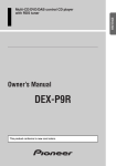
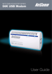
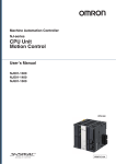
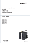
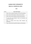
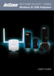
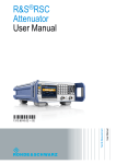
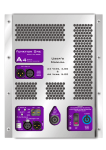
NetComm Velocity™ Series Wireless Network Link USER GUIDE Contents Introduction................................................................................................................................................................................................3 Your NetComm Velocity Series Wireless Network Link.......................................................................................................................................................4 Package Contents......................................................................................................................................................................................................4 Key Features...............................................................................................................................................................................................................4 Placement of your Wireless Network Link ...............................................................................................................................................5 1. AP Placement...............................................................................................................................................................................................................6 2. Avoid obstacles and interference...................................................................................................................................................................................6 3. Cordless Phones...........................................................................................................................................................................................................6 4. Choose the “Quietest” Channel for your Wireless Network............................................................................................................................................6 Product Layout...........................................................................................................................................................................................7 Connecting and Configuring your kit........................................................................................................................................................9 Network and System Requirements................................................................................................................................................................................10 Modem Requirements.....................................................................................................................................................................................................10 Connecting your AP........................................................................................................................................................................................................10 Configuring your CB........................................................................................................................................................................................................10 Configuring your NP121..................................................................................................................................................................................................10 AP Mode – Advanced Features...............................................................................................................................................................11 Login Procedure..............................................................................................................................................................................................................12 Status ............................................................................................................................................................................................................................13 LAN................................................................................................................................................................................................................................13 Log.................................................................................................................................................................................................................................14 Monitor...........................................................................................................................................................................................................................14 Wizard............................................................................................................................................................................................................................14 Wireless Settings.............................................................................................................................................................................................................15 Basic........................................................................................................................................................................................................................15 Advanced.................................................................................................................................................................................................................16 Security...........................................................................................................................................................................................................................17 Enable 802.1x Authentication...................................................................................................................................................................................17 WEP Encryption........................................................................................................................................................................................................18 WPA Pre-shared Key Encryption...............................................................................................................................................................................18 WPA Radius Encryption............................................................................................................................................................................................19 Mac Address Filtering...............................................................................................................................................................................................19 Wi-Fi Protected Setup (WPS)....................................................................................................................................................................................20 Client list...................................................................................................................................................................................................................20 Tools Settings..................................................................................................................................................................................................................21 Time.........................................................................................................................................................................................................................21 Diagnosis..................................................................................................................................................................................................................22 Firmware...................................................................................................................................................................................................................22 Back-up...................................................................................................................................................................................................................22 Reset........................................................................................................................................................................................................................22 Client Bridge Mode..................................................................................................................................................................................23 Wireless .........................................................................................................................................................................................................................24 Basic........................................................................................................................................................................................................................24 Advanced.................................................................................................................................................................................................................25 WPS.........................................................................................................................................................................................................................25 AP Profile..................................................................................................................................................................................................................25 Repeater Mode.........................................................................................................................................................................................27 Appendix: Legal and Regulatory Information.........................................................................................................................................29 Wireless Network Link User Guide YML121 www.netcomm.com.au Introduction Lets get to know each other Introduction Your NetComm Velocity Series Wireless Network Link Congratulations on your purchase of a NetComm Velocity Series Wireless Network Link. The Wireless Network Link provides you with a simple method for transporting an Internet connection from one point to another. Simply plug the Access Point (which is clearly labeled) into your existing broadband modem/router and plug the Client Bridge (also clearly labeled) into the device which you want to be able to access the Internet. The pre-configured kit will take care of the rest. It is just like running a cable directly from your modem. With speeds of up to 300Mbps* the NetComm Velocity Series Wireless Network Link uses advanced MIMO (Multi-Input, Multi-Output) technology to transmit multiple steams of data in a single wireless channel giving you seamless access to multimedia content. Robust RF signal travels farther, eliminates dead spots and extends network range. For data protection and privacy, the kit comes preconfigured with a unique wireless network name and security password. At any time you are able to push the WPS button which will reassign another unique name and password ensuring all of your data is safe and has a clear path to travel. Package Contents 1. 1 x Wireless Access Point 2. 1 x Wireless Client Bridge 3. 2 x RJ45 Ethernet networking cables 4. 2 x Power supplies 5.Resource CD with user manual 6. Printed Quick Start Guide 7. 2 x 2dBi 2.4GHz antennas Key Features - Two pre-paired wireless routers allow for the simplest possible setup of a wireless network connection - Wireless N for speeds of up to 300Mbps* -Increase your network speed, reliability and coverage - 4 Ethernet ports for wired connections at each end - No more Ethernet cables running across the floor - Plug and play simplicity * Maximum wireless signal rate and coverage values are derived from IEEE Standard 802.11g and 802.11n specifications. Actual wireless speed and coverage are dependent on network and environmental conditions included but not limited to volume of networking traffic, building materials and construction/layout Wireless Network Link User Guide YML121 www.netcomm.com.au Placement Three little words ... location, location, location Placement of your Wireless Network Link Your wireless connection will be stronger the closer the Access Point and Bridge are to each other. Your wireless connection and performance will degrade as the distance between your kit increases. This may or may not be noticeable. If you have concerns about your network’s performance that might be related to range or obstruction factors, try moving the computer to a position between three to five meters from the Access Point (AP) in order to see if distance is the problem. If difficulties persist even at close range, please contact NetComm Technical Support. Note: While some of the items listed below can affect network performance, they will not prohibit your wireless network from functioning; if you are concerned that your network is not operating at its maximum effectiveness, this checklist may help. 1. AP Placement Place your AP, as close as possible to your Client Bridge (CB). To achieve the best wireless network coverage for your CB. • Ensure that your antennas are parallel to each other, and are positioned vertically (toward the ceiling). • Try not to place the Router near a cordless 2.4GHz phone. 2. Avoid Obstacles and Interference Avoid placing your kit near devices that may emit radio “noise,” such as microwave ovens. Dense objects that can inhibit wireless communication include: • Refrigerators • Washers and/or dryers • Metal cabinets • Large aquariums • Metallic-based, UV-tinted windows If your wireless signal seems weak in some spots, make sure that objects such as these are not blocking the signal’s path (between your Access Point and Client Bridge). 3. Cordless Phones If the performance of your wireless network is impaired after attending to the above issues, and you have a cordless phone: • Try moving cordless phones away from your kit. • Unplug and remove the battery from any cordless phone that operates on the 2.4GHz band (check manufacturer’s information). If this fixes the problem, your phone may be interfering. • If your phone supports channel selection, change the channel on the phone to the farthest channel from your wireless network. For example, change the phone to channel 1 and move your kit to channel 11. See your phones user manual for detailed instructions. • If necessary, consider switching to a 900MHz or 5GHz cordless phone. 4. Choose the “Quietest” Channel for your Wireless Network In locations where homes or offices are close together, such as apartment buildings or office complexes, there may be wireless networks nearby that can conflict with yours. Use the Site Survey capabilities found in the Wireless Utility of your wireless adapter to locate any other wireless networks that are available (see your wireless adapter’s user manual), and move your kit to a channel as far away from other networks as possible. • Experiment with more than one of the available channels, in order to find the clearest connection and avoid interference from neighbouring cordless phones or other wireless devices. • For NetComm wireless networking products, use the detailed Site Survey and wireless channel information included with your wireless network card. See your network card’s user guide for more information. These guidelines should allow you to cover the maximum possible area with your kit. Wireless Network Link User Guide YML121 www.netcomm.com.au How to configure WEP/WPA-PSK/WPA2-PSK Product Layout Wireless Security Or ... “What do all these flashing lights mean?” Product Layout The Wireless Network Link has been designed to be placed on a desktop. All of the cables exit from the rear of the kit for better organization. The display is easily visible on the FRONT of the device to provide you with information about network activity and status. See below for explanation of each of the features. Front LEDS POWER 2 3 4 Lights up 1when powered ON. Blinks on TEST/RESET Reset WPS WWW NP802n - 802.11n wireless router with 4 Gigabit Ethernet ports 1 3 Reseton traffic Lights up 2when WLAN is4 enabled. Blinks WLAN WPS (Wireless LAN) PORT ACTIVITY WWW NP802n - 802.11n wireless router with 4 Gigabit Ethernet ports WPS LAN 1 2 4 Blinks on 3traffic for specific LANReset PORT WWW Final Panel Lights up when the AP and CB are successfully paired. Final Panel RearFinal Ports Panel NP802n - 802.11n wireless router with 4 Gigabit Ethernet ports (Cyan Is LED light shining through) Status (Cyan Is LED light shining through) (Cyan Is LED light shining through) Click this button for less than three seconds for WPS, or Press this button and hold for 10 seconds to reset to factory defaults. Reset Reset/WPS WPS LAN1 ~WPS 4 POWER WPS WWW NP802n - 802.11n wireless router with 4 Gigabit Ethernet ports Local Area Network (LAN) ports 1 to 4 Reset WWW Power connector, connects to DC 12V Power Adapter Printing Black Printing Black Printing Black NP802n - 802.11n wireless router with 4 Gigabit Ethernet ports Reset WWW NP802n - 802.11n wireless router with 4 Gigabit Ethernet ports 1 1 2 3 2 3 4 Printing White Printing White Printing White 1 2 3 4 4 (white above is transparent) (white above is transparent) (white above is transparent) Wireless Network Link User Guide YML121 www.netcomm.com.au Connecting andWEP/WPA-PSK/WPA2-PSK Configuring your Wireless Networking Kit How to configure Wireless Security The blue cable goes where now? Connecting and Configuring your Wireless Network Link Network + System Requirements To begin using the Velocity Series, make sure you meet the following as minimum requirements: • Internet enabled device that you want to connect with an Ethernet port (RJ-45) • External xDSL (ADSL) or Cable modem with an Ethernet port (RJ-45). Modem Requirements Your cable or DSL modem must be equipped with an RJ45 Ethernet port. Many modems have both an RJ45 Ethernet port and a USB connection. If you have a modem with both Ethernet and USB, and are using the USB connection at this time, you will be instructed to use the RJ45 Ethernet port during the installation procedure. If your modem has only a USB port, you can request a different type of modem from your ISP, or you can purchase a modem that has an RJ45 Ethernet port on it. Connecting your Access Point (AP) A Attach your antenna. Place your AP next to your modem. Unplug your modem’s power cord. B Find your new networking cable (included in the box with your Wireless Network Link) and connect it to the LAN port on the back of the Velocity Series AP. Connect the other end to your modem’s LAN Port. C Plug in your modem’s power cord. Wait 60 seconds for the modem to start up. Plug the Velocity Series AP’s power supply into the power socket on the back. Plug the other end into the wall outlet. Turn on the power outlet. D Wait 20 seconds for the AP to start up. Look at the display on the front of the AP. Make sure the “Power”, “LAN” icons are lit up in blue. If they are not, recheck your connections. Connecting your Client Bridge (CB) A Attach your antenna. Place your CB next to the device/s that you want to connect. B Find the other networking cable (included in the box with your Wireless Network Link) and connect it to the LAN port on the back of the Velocity Series CB. Connect the other end to the free LAN Port on your device/s. C Plug in the CB’s power supply into the power socket on the back of your device. Plug the other end into the wall outlet. Turn on the power outlet. D Wait 20 seconds for the CB to start up. Look at the display on the front of the CB. Make sure the “Power”, “LAN” and “STATUS” icons are lit up in blue. If they are not, recheck your connections. Configuring Your NP121 To get into the web user interface of your AP and CB configure your computer to static IP Address 192.168.20.x (where x cannot be 2 or 3) To do this: A Click Start > Run. Type ncpa.cpl and press enter. B In Network connections right click on Local Area Connection and choose Properties. C Highlight Internet protocol (TCP/IP) [V4 for vista or later] and click Properties. D Select Use the following IP address: IPaddress:192.168.20.50 Subnet mask: 255.255.255.0 Default gateway: BLANK E Select use the following DNS addresses: Primary DNS: BLANK Alternate DNS: BLANK F Click Ok and close the properties windows of the Local Area connection. G Open Internet Explorer and type in 192.168.20.2 on address bar of Web Browser. The login Username and Password are both "admin". Wireless Network Link User Guide 10 YML121 www.netcomm.com.au How to configure WEP/WPA-PSK/WPA2-PSK AP Mode Wireless Security Configuring your Access Point ... Waitaminute, I have an Access Point? AP Mode The Wireless Network Link uses a web-interface for configuration to be accessed through your web browser, such as Internet Explorer or Netscape Communicator. Login Procedure 1. Open your browser (e.g. Internet Explorer). 2. Type http://192.168.20.2 in address bar and hit [Enter] button on your keyboard. Type in the default:User name - admin Password - admin Then Click <OK> to navigate into the Wireless Network Link configuration home page. 3. You will see the home page of Wireless Network Link as follows. Wireless Network Link User Guide 12 YML121 www.netcomm.com.au NetComm Velocity™ Series Wireless Network Link Status You can see the UP time, hardware information, serial number as well as firmware version information. LAN This section displays the NP121 LAN port’s current information. It also shows whether the DHCP Server function is enabled / disabled. IP address: 192.168.20.2. It is the NP121 AP’s LAN IP address (Your LAN clients default gateway IP address). It can be changed based on your own choice. IP Subnet Mask: 255.255.255.0 Specify a Subnet Mask for your LAN segment. 802.1d Spanning Tree: This is disabled by default. If 802.1d Spanning Tree function is enabled, this router will use the spanning tree protocol to prevent network loops. DHCP Server: This will enable or disable the Dynamic Pool setting. Lease time: This is the lease time of each assigned IP address. Start IP: This will be the beginning of the pool of IP addresses available for client devices. End IP: This will be the end of the pool of IP addresses available for client devices. Domain name: The Domain Name for the existing or customized network. YML������������������������������������ 121��������������������������������� �������������������������������� Wireless Network Link User Guide www.netcomm.com.au 13 Log View operation event log. This page shows the current system log of the NP121. It displays any event occurred after system start up. At the bottom of the page, the system log can be saved <Save> to a local file for further processing or the system log can be cleared <Clear> or it can be refreshed <Refresh> to get the most updated information. When the system is powered down, the system log will disappear if not saved to a local file. Monitor Show histogram for network connection on LAN & WLAN. Auto refresh keeps information updated frequently. Wizard Click Wizard to configure the NP121. Setup wizard will now be displayed; check that the modem is connected and click <Next>. Wireless Network Link User Guide 14 YML121 www.netcomm.com.au NetComm Velocity™ Series Wireless Network Link Wireless Settings Basic In basic setting page, you can set wireless Radio, Mode, Band, SSID, and Channel. Radio: You can turn on/off the wireless radio. If the wireless Radio is off, you cannot associate with the AP through wireless. Mode: In this device, we support three operation modes which are AP router, Client Bridge and AP repeater. Band: You can select the wireless standards running on your network environment. • 2.4 GHz(B): If all your clients are 802.11b, select this one. • 2.4 GHz(N): If all your clients are 802.11n, select this one. • 2.4 GHz(B+G): Either an 802.11b or an 802.11g wireless devices are in your environment. • 2.4 GHz(G): If all your clients are 802.11g, select this one. • 2.4 GHz(B+G+N): Either 802.11b, 802.11g, or 802.11n wireless devices are in your environment. Enable SSID: This device supports up to 4 SSIDs. Select the number you would like to use in your network. SSID1~4: SSID is the name of your wireless network. Use a unique name to identify this wireless device in the Wireless LAN. It is case sensitive and up to 32 characters. You should change the default SSID for added security. Auto Channel: Device will search all valid channels, then decide a most clean channel and change to this channel if you enable this function. Depend on this function enable or not, you will see different item below Auto Channel. Channel: If Auto Channel is disabled, choose a static channel; AP will use this to communicate with other clients. Check Channel Time: If Auto Channel is enabled, you can choose a period from the drop-down menu. AP will change to a clean channel periodically YML������������������������������������ 121��������������������������������� �������������������������������� Wireless Network Link User Guide www.netcomm.com.au 15 Advanced This tab allows you to set the advanced wireless options. You should not change these parameters unless you know what effect the changes will have on the router. Fragment Threshold: This specifies the maximum size of a packet during the fragmentation of data to be transmitted. If you set this value too low, it will result in bad performance. RTS Threshold: When the packet size is smaller than the RTS threshold, the wireless router will not use the RTS/CTS mechanism to send this packet. Beacon Interval: Interval of time the wireless router broadcasts a beacon, used to synchronize the wireless network. DTIM Period: Enter a value between 1 and 255 for the Delivery Traffic Indication Message (DTIM). A DTIM is a countdown informing clients of the next window for listening to broadcast and multicast messages Data Rate: The “Data Rate” is the rate that this access point uses to transmit data packets. The access point will use the highest possible selected transmission rate to transmit the data packets. N Data Rate: The “Data Rate” is the rate that this access point uses to transmit data packets for N compliant wireless nodes. Channel Bandwidth: This is the range of frequencies that will be used. Preamble Type: The “Long Preamble” can provide better wireless LAN compatibility while the “Short Preamble” can provide better wireless LAN performance. CTS Protection: It is recommended to enable the protection mechanism. This mechanism can decrease the rate of data collision between 802.11b and 802.11g wireless stations. When the protection mode is enabled, the throughput of the AP will be a little lower due to a lot of frame-network that is transmitted. TX Power: This can be set to a bare minimum or maximum power Wireless Network Link User Guide 16 YML121 www.netcomm.com.au NetComm Velocity™ Series Wireless Network Link Security This Access Point provides complete wireless LAN security functions, included are WEP, IEEE 802.1x, IEEE 802.1x with WEP, WPA with pre-shared key and WPA with RADIUS. With these security functions, you can prevent your wireless LAN from illegal access. Please make sure your wireless stations use the same security function, and are setup with the same security key. SSID Selection: This NP121 support multiple SSID, you could select and set up the wanted SSID. Broadcast SSID: If you enabled “Broadcast SSID”, every wireless station located within the coverage of this access point can discover this access point easily. If you are building a public wireless network, enabling this feature is recommended. Disabling “Broadcast SSID” can provide better security. WMM: If enabled supports multimedia QoS for experiencing better audio, video and voice in applications. Encryption: When you choose to disable encryption, your network is unsecured. Enable 802.1x Authentication IEEE 802.1x is an authentication protocol. Every user must use a valid account to login to this Access Point before accessing the wireless LAN. The authentication is processed by a RADIUS server. This mode only authenticates users by IEEE 802.1x, but it does not encrypt the data during communication. YML������������������������������������ 121��������������������������������� �������������������������������� Wireless Network Link User Guide www.netcomm.com.au 17 WEP Encryption When you select 64-bit or 128-bit WEP key, you have to enter WEP keys to encrypt data. You can generate the key by yourself and enter it. You can enter four WEP keys and select one of them as a default key. Then the router can receive any packets encrypted by one of the four keys. Authentication Type: There are two authentication types: “Open System” and “Shared Key”. When you select “Open System”, wireless stations can associate with this wireless router without WEP encryption. When you select “Shared Key”, you should also setup a WEP key in the “Encryption” page. After this has been done, make sure the wireless clients that you want to connect to the device are also setup with the same encryption key. Key Length: You can select the WEP key length for encryption, 64-bit or 128-bit. The larger the key will be the higher level of security is used, but the throughput will be lower. Key Type: You may select ASCII Characters (alphanumeric format) or Hexadecimal Digits (in the “A-F”, “a-f” and “0-9” range) to be the WEP Key. Key1 - Key4: The WEP keys are used to encrypt data transmitted in the wireless network. Use the following rules to setup a WEP key on the device. 64-bit WEP: input 10-digits Hex values (in the “A-F”, “a-f” and “0-9” range) or 5-digit ASCII character as the encryption keys. 128-bit WEP: input 26-digit Hex values (in the “A-F”, “a-f” and “0-9” range) or 13-digit ASCII characters as the encryption keys. Click <Apply> at the bottom of the screen to save the above configurations. You can now configure other sections by choosing Continue, or choose Apply to apply the settings and reboot the device. WPA Pre-Shared Key Encryption Wi-Fi Protected Access (WPA) is an advanced security standard. You can use a pre-shared key to authenticate wireless stations and encrypt data during communication. It uses TKIP or CCMP (AES) to change the encryption key frequently. So the encryption key is not easy to be cracked by hackers. This is the best security available. Wireless Network Link User Guide 18 YML121 www.netcomm.com.au NetComm Velocity™ Series Wireless Network Link WPA-Radius Encryption Wi-Fi Protected Access (WPA) is an advanced security standard. You can use an external RADIUS server to authenticate wireless stations and provide the session key to encrypt data during communication. It uses TKIP or CCMP (AES) to change the encryption key frequently. Press <Apply> button when you are done. MAC Address Filtering This wireless router supports MAC Address Control, which prevents unauthorized clients from accessing your wireless network. Enable wireless access control: Enable the wireless access control function Adding an address into the list Enter the “MAC Address” and “Comment” of the wireless station to be added and then click <Add>. The wireless station will now be added into the “Current Access Control List” below. If you are having any difficulties filling in the fields, just click “Clear” and both “MAC Address” and “Comment” fields will be cleared. Remove an address from the list If you want to remove a MAC address from the “Current Access Control List “, select the MAC address that you want to remove in the list and then click “Delete Selected”. If you want to remove all the MAC addresses from the list, just click the <Delete All> button. Click <Reset> will clear your current selections. Click <Apply> at the bottom of the screen to save the above configurations. YML������������������������������������ 121��������������������������������� �������������������������������� Wireless Network Link User Guide www.netcomm.com.au 19 Wi-Fi Protected Setup (WPS) WPS is the simplest way to establish a connection between wireless clients and the wireless router. You don’t have to select the encryption mode and fill in a passphrase. You only need to press a button on both wireless client and wireless router, and the WPS will do the rest for you. The wireless router supports two types of WPS. WPS via Push Button – you have to push a specific button on the wireless client or in your wireless client utility to start the WPS mode, and switch the wireless router to WPS mode. You can simply click the ‘Start to Process’ button in the web configuration interface. WPS via PIN code – you have to know the PIN code of the wireless client and switch it to WPS mode, then input the wireless client PIN to the wireless router web interface. WPS: Check the box to enable WPS function and uncheck it to disable the WPS function. WPS Current Status: If the wireless security (encryption) function of this wireless router is properly set, you’ll see a ‘Configured’ message here. Otherwise, you’ll see ‘UnConfigured’. Self Pin Code: This is the WPS PIN code of the wireless router. You may need this information when connecting to other WPS-enabled wireless devices. SSID: This is the network broadcast name (SSID) of the router. Authentication Mode: It shows the active authentication mode for the wireless connection. Passphrase Key: It shows the passphrase key that is randomly generated by the wireless router during the WPS process. You may need this information when using a device which doesn’t support WPS. Interface: If the device is set to repeater mode, you can choose “Client” interface to connect with other AP by using WPS, otherwise you may choose “AP” interface to do WPS with other clients. WPS via Push Button: Press the button to start the WPS process. The router will wait for the WPS request from the wireless devices within 2 minutes. WPS via PIN: You can fill-in the PIN code of the wireless device and press the button to start the WPS process. The router will wait for the WPS request from the wireless device within 2 minutes. Client List This WLAN Client Table shows the Wireless clients associated to this Wireless Router. Wireless Network Link User Guide 20 YML121 www.netcomm.com.au NetComm Velocity™ Series Wireless Network Link Tools Settings You can change the password required to log into the NP121 system web-based management. By default, the password is admin. Passwords can contain 0 to 12 alphanumeric characters, and are case sensitive. Current Password: Fill in the current password to allow changing to a new password. New Password: Enter your new password. Repeat New Password for verification purposes Time The Time Zone allows your router to reference or base its time on the settings configured here, which will affect functions such as Log entries and Firewall settings. Time Zone: Select the time zone of the country you are currently in. The router will set its time based on your selection. NTP Time Server: The router can set up external NTP Time Server. Daylight Savings: The router can also take Daylight Savings into account. If you wish to use this function, you must select the Daylight Savings Time period and check/tick the enable box to enable your daylight saving configuration. Click <Apply> at the bottom of the screen to save the above configurations. YML������������������������������������ 121��������������������������������� �������������������������������� Wireless Network Link User Guide www.netcomm.com.au 21 Diagnosis This page describes your current network status. Firmware This page allows you to upgrade the router’s firmware. To upgrade the firmware of your NP121, you need to download the firmware file to your local hard disk, and enter that file name and path in the appropriate field on this page. You can also use the Browse button to find the firmware file on your PC. Once you’ve selected the new firmware file, click <Apply> at the bottom of the screen to start the upgrade process Back-up This page allows you to save the current router configurations. When you save the configurations, you also can re-load the saved configurations into the router through the Restore Settings. If extreme problems occur you can use the Restore to Factory Default: Sets all configurations to its original default settings. Backup Settings: This can save the NP121 current configuration to a file named “config.bin” on your PC. You can also use the <Upload> button to restore the saved configuration to the NP121. Alternatively, you can use the “Restore to Factory Defaults” tool to force the NP121 to perform a power reset and restore the original factory settings. Reset You can reset the NP121 if the system stops responding correctly or functions stop. Wireless Network Link User Guide 22 YML121 www.netcomm.com.au Client Bridge Mode Configure Your Client Bridge ... AKA How to calm a bridge over troubled waters Client Bridge Mode The NP121 CB is working in Client Bridge Mode as default. Click on the Status link under the System menu. This page will display the current wireless settings such as SSID, Channel, Security and BSSID (MAC address) Wireless Basic Mode: This drop-down list is fixed to Client as this is the Client Bridge operating mode. Band: Select the IEEE 802.11 mode from the drop-down list. For example, if you are sure that the wireless network will be using only IEEE 802.11g clients, then it is recommended to select 802.11g only instead of 2.4 GHz B+G which will reduce the performance of the wireless network. You may also select 802.11B+G+N. If all of the wireless devices you want to connect with this router can connect in the same transmission mode, you can improve performance slightly by choosing the appropriate “Only” mode. If you have some devices that use a different transmission mode, choose the appropriate “Mixed” mode. Site Survey: Click on the Site Survey button to view a list of Access Points in the area. The Site Survey page displays information about devices within the 802.11b/g/n frequency. Information such as channel, SSID, BSSID, encryption, authentication, signal strength, and operating mode are displayed. Select the desired device and then click on the Add to AP Profile button SSID: The SSID is a unique name that is shared amongst all the points of the wireless network. The SSID must be identical on all points of the wireless network and cannot exceed 32 characters. Status: Displays the current status of the device. Channel: The channels available are based on the country’s regulation. A wireless network uses specific channels in the wireless spectrum to handle communication between clients. Some channels in your area may have interference from other electronic devices. Click on the Add to AP Profile button to save the changes. Wireless Network Link User Guide 24 YML121 www.netcomm.com.au NetComm Velocity™ Series Wireless Network Link Advanced Fragment Threshold: Packets over the specified size will be fragmented in order to improve performance on noisy networks. Specify a value between 256 and 2346. The default value is 2346. RTS Threshold: Packets over the specified size will use the RTS/CTS mechanism to maintain performance in noisy networks and preventing hidden nodes from degrading the performance. Specify a value between 0 and 2347. The default value is 2347. TX Power: This can be set to a bare minimum or maximum power. Click on the Apply button to save the changes. WPS This interface allows you to activate client WPS and synchronize with other AP’s. Click [Start to Process] to initiate the WPS process. It serves the same purpose as the WPS button on the device. AP Profile Click on the AP Profile link under the Wireless drop-down menu. This page allows you to configure the profile of the Client Bridge including Security Setting exactly the same as the Access Point. YML������������������������������������ 121��������������������������������� �������������������������������� Wireless Network Link User Guide www.netcomm.com.au 25 Manage AP Profile 1. Press Add/Edit to add/modify the SSID(s) of your device. 2. Set Encryption type from the Encryption dropdown list. 3. Press Save to save your setting. 4. Check one of the SSID in the table to Move Up or Move Down the display order 5. Delete Selected to delete the SSID on check. 6. Delete All to delete all SSID from the table 7. Connect to configure your device using the SSID on check Wireless Network Link User Guide 26 YML121 www.netcomm.com.au Repeater Mode Operate as a repeater, Operate as a repeater, Operate as a repeater Repeater Mode Advanced Features Repeater mode has limited settings compared to the AP mode. Run the Wizard and choose “AP Repeater mode”, System restarts and connects to the IP address http://192.168.20.2 You will see the configuration homepage under “REPEATER” mode now. Wireless Network Link User Guide 28 YML121 www.netcomm.com.au Appendix Sure I had this removed? Legal & Regulatory Information This manual is copyright. Apart from any fair dealing for the purposes of private study, research, criticism or review, as permitted under the Copyright Act, no part may be reproduced, stored in a retrieval system or transmitted in any form, by any means, be it electronic, mechanical, recording or otherwise, without the prior written permission of NetComm Limited. NetComm Limited accepts no liability or responsibility, for consequences arising from the use of this product. NetComm Limited reserves the right to change the specifications and operating details of this product without notice. NetComm is a registered trademark of NetComm Limited. All other trademarks are acknowledged the property of their respective owners. Product Warranty The warranty is granted on the following conditions: 1. This warranty extends to the original purchaser (you) and is not transferable; 2. This warranty shall not apply to software programs, batteries, power supplies, cables or other accessories supplied in or with the product; 3. The customer complies with all of the terms of any relevant agreement with NetComm and any other reasonable requirements of NetComm including producing such evidence of purchase as NetComm may require; 4. The cost of transporting product to and from NetComm’s nominated premises is your responsibility; and, 5. NetComm does not have any liability or responsibility under this warranty where any cost, loss, injury or damage of any kind, whether direct, indirect, consequential, incidental or otherwise arises out of events beyond NetComm’s reasonable control. This includes but is not limited to: acts of God, war, riot, embargoes, acts of civil or military authorities, fire, floods, electricity outages, lightning, power surges, or shortages of materials or labour. 6.The customer is responsible for the security of their computer and network at all times. Security features may be disabled within the factory default settings. NetComm recommends that you enable these features to enhance your security. The warranty is automatically voided if: 1. You, or someone else, use the product, or attempts to use it, other than as specified by NetComm; 2. The fault or defect in your product is the result of a voltage surge subjected to the product either by the way of power supply or communication line, whether caused by thunderstorm activity or any other cause(s); 3. The fault is the result of accidental damage or damage in transit, including but not limited to liquid spillage; 4. Your product has been used for any purposes other than that for which it is sold, or in any way other than in strict accordance with the user manual supplied; 5. Your product has been repaired or modified or attempted to be repaired or modified, other than by a qualified person at a service centre authorised by NetComm; and, 6. The serial number has been defaced or altered in any way or if the serial number plate has been removed. Limitations of Warranty The Trade Practices Act 1974 and corresponding State and Territory Fair Trading Acts or legalisation of another Government (“the relevant acts”) in certain circumstances imply mandatory conditions and warranties which cannot be excluded. This warranty is in addition to and not in replacement for such conditions and warranties. To the extent permitted by the Relevant Acts, in relation to your product and any other materials provided with the product (“the Goods”) the liability of NetComm under the Relevant Acts is limited at the option of NetComm to: •Replacement of the Goods; or •Repair of the Goods; or • Payment of the cost of replacing the Goods; or • Payment of the cost of having the Goods repaired. All NetComm ACN 002 490 486 products have a standard 12 months warranty from date of purchase. However some products have an extended warranty option (refer to packaging). To be eligible for the extended warranty you must supply the requested warranty information to NetComm within 30 days of the original purchase by registering on-line via the NetComm web site at www.netcomm.com.au Wireless Network Link User Guide 30 YML121 www.netcomm.com.au NetComm Velocity™ Series Wireless Network Link NETCOMM LIMITED Head Office PO Box 1200, Lane Cove NSW 2066 Australia P: 02 9424 2070 F: 02 9424 2010 E: [email protected] W: www.netcommlimited.com. DYNALINK NZ 12C Tea Kea Place, Albany, Auckland, New Zealand P: 09 448 5548 F: 09 448 5549 E: [email protected] W: www.dynalink.co.nz Product Warranty NetComm products have a standard 12 months warranty from date of purchase. However some products have an extended warranty option, via registering your product online at the NetComm website www.netcommlimited.com. Technical Support If you have any technical difficulties with your product, please refer to the support section of our website. www.netcomm.com.au/support Note:NetComm Technical Support for this product only covers the basic installation and features outlined in the Quick Start Guide. For further information regarding the advanced features of this product, please refer to the configuring sections in the User Guide or contact a Network Specialist. Trademarks and registered trademarks are the property of NetComm Limited or their respective owners. Specifications are subject to change without notice. Images shown may vary slightly from the actual product. YML������������������������������������ 121��������������������������������� �������������������������������� Wireless Network Link User Guide www.netcomm.com.au 31