1
Chapter 15
Impedance Applications
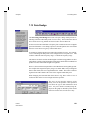
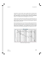
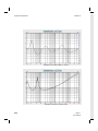
Since a voltage sweep will be taken and then used when divided by the current
sweep, the frequency response of the amplifier will be cancelled out. This dramatically reduces the demand of a perfectly flat response for the amplifier. This is very
helpful.
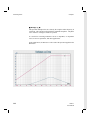
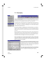
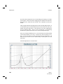
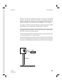
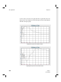
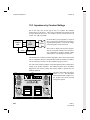
In this example, a 3 way enclosure will be measured. The impedance will be
determined at three different power levels: 0.1W, 1W, and 10W. Based on a
nominal Z of 8 Ohms.
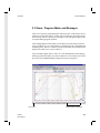
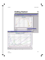
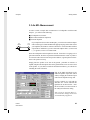
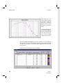
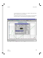
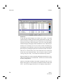
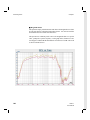
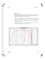
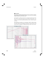
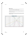
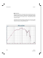
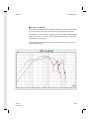
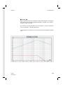
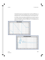
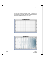
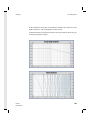
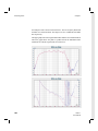
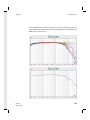
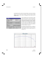
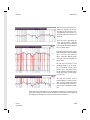
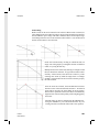
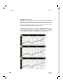
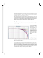
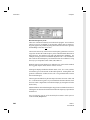
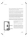
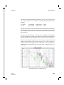
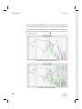
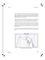
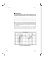
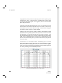
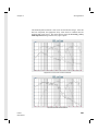
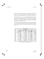
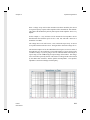
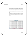
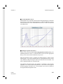
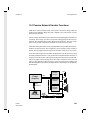
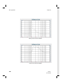
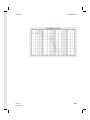
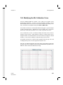
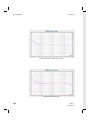
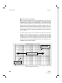
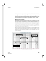
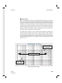
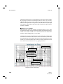
The voltage drive levels will be 0.9V, 2.83V, and 9Volts respectively. A current
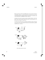
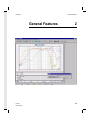
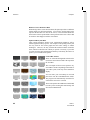
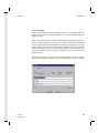
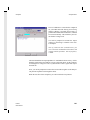
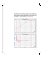
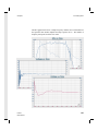
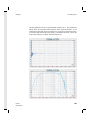
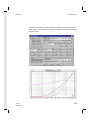
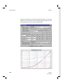
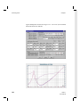
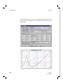
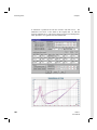
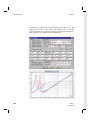
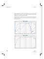
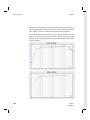
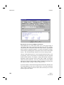
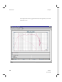
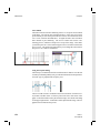
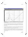
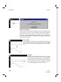
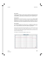
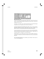
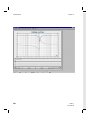
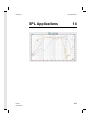
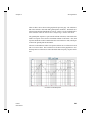
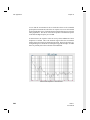
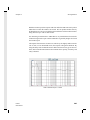
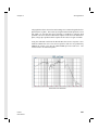
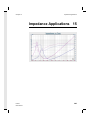
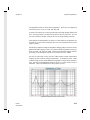
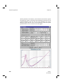
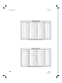
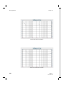
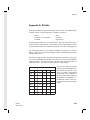
sweep will be taken at each drive level. The figure below shows the voltage curves.
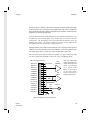
The maximum input level for the LMS balanced line input is 8 Vrms on either of
the signal pins 2/3. Be careful not to exceed this input level, power amps can far
exceed this voltage! If you are going to do a lot of measurements at the output of
a power amp, use the -40dB setting for output voltage on the VI-Box. The voltage
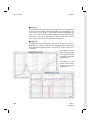
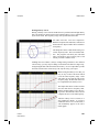
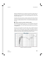
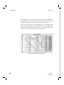
curves will not be a perfectly flat line. This is due to a voltage divider effect caused
by the shunt+cable resistance, and the speaker load impedance. The speaker's
impedance is not flat but changes with frequency.
LMS 4.1
User Manual
311