1
Introduction to the General Campaign Analysis
Model (GCAM) Version 3.3
James Caunce 1 , Greg Searle 2
1
Joint Operations Division
2
Midspar Systems Pty Ltd
Defence Science and Technology Organisation
DSTO–GD–0591
ABSTRACT
This document gives an introduction to the General Campaign and Analysis
Model (GCAM) Version 3.3. GCAM is a set of tools for developing agentbased, time-stepped models of operations. This document is intended to give
a general understanding of the way GCAM works, complimenting the existing documentation. Contained in this document are a brief description of the
concepts that GCAM employs, a tutorial guiding the reader through an introductory scenario, an indication of features not covered in this document and
references for further guidance.
APPROVED FOR PUBLIC RELEASE
DSTO–GD–0591
Published by
DSTO Defence Science and Technology Organisation
DSTO Fern Hill,
Department of Defence, Canberra 2600, ACT
Telephone:
Facsimile:
(02) 6256 6100
(03) 6256 6103
c Commonwealth of Australia 2009
AR No. AR 014–630
September, 2009
APPROVED FOR PUBLIC RELEASE
ii
DSTO–GD–0591
Introduction to the General Campaign Analysis Model
(GCAM) Version 3.3
Executive Summary
This document provides an introduction to the General Campaign Analysis Model
(GCAM). GCAM is a set of tools for developing time-stepped, agent-based models that are
best suited to modelling air and sea units in maritime environment operations. The tools
occupy the middle-ground between the flexibility of programming languages (like C++
and Java) and high-level models (like ITEM and JICM) that allow rapid development and
analysis.
GCAM models, or scenarios, are written in a custom language called COOML. GCAM
is made up of three tools: ObjectManager, GAME and Case Launcher. ObjectManager is
a model development environment for writing and checking COOML code. GAME is the
environment for running the scenarios, providing graphical displays and numerical data.
Case Launcher is a tool for running a scenario multiple times in batch-processing mode.
There are four main concepts that need to be understood when learning how to use
GCAM: maps; units; statistics, conditions and triggers; and phases. Maps form the main
visual presentation in GAME and are the backdrop onto which campaign actions are
overlaid. Every entity in GCAM is a unit, for example locations, military units or graphical
displays. Units are displayed as sprites on the map and have various properties and
orders given to them. Statistics, conditions and triggers provide the mechanism for logical
statements to be executed and are primarily used in defining the units’ behaviour. A
phase is a mode of operation that some of a unit’s properties can be set to go through, for
example to turn a unit’s radar on when needed. A change in phase is caused by a trigger.
This report contains a tutorial on creating a simple scenario to help the reader become
familiar with the general usage of GCAM. The tutorial covers: starting ObjectManager;
creating a master file and subsidiary files; defining maps, sprites, units and unit behaviour;
and running GAME. The tutorial scenario simulates a Blackhawk helicopter flying from
Cairns to Townsville, picking up troops there and transporting them back to to Cairns.
After completing the tutorial, a user should be in a position to start to build their own
simple scenarios with the help of the existing GCAM documentation.
There are many features of GCAM not covered in the tutorial, they are listed here to
bring them to the reader’s attention. Some features are available through the unit file,
including: 22 different types of movement that can be given to a unit (for example follow
and search); unit inventories (like fuel or ammunition); damage and repair of units; and
queues of data can be associated with units (maybe a list of targets). Other files provide
additional functions: the sensors file, where sensors such as radar are defined; unit class
files that allow units to inherit the properties of their class; the output control file for
defining output; the graph control file for plotting graphs; the display file to display text
or video in GAME; and the mapview overlay file to put text and shapes onto the maps.
There are several other resources that should be consulted in conjunction with this
report, including the GCAM documentation, and the presentations and example scenarios
that exist at DSTO. This document is only an introduction and the next step is for a user
to gain experience by developing their own scenario.
iii
DSTO–GD–0591
iv
DSTO–GD–0591
Contents
1
Introduction
1
2
GCAM basics
1
2.1
Maps . . . . . . . . . . . . . . . . . . . . . . . . . . . . . . . . . . . . . .
2
2.2
Units . . . . . . . . . . . . . . . . . . . . . . . . . . . . . . . . . . . . . .
2
2.3
Statistics, conditions and triggers . . . . . . . . . . . . . . . . . . . . . . .
4
2.3.1
Statistics . . . . . . . . . . . . . . . . . . . . . . . . . . . . . . . .
4
2.3.2
Conditions . . . . . . . . . . . . . . . . . . . . . . . . . . . . . . .
4
2.3.3
Triggers . . . . . . . . . . . . . . . . . . . . . . . . . . . . . . . .
4
Phases and phaselists . . . . . . . . . . . . . . . . . . . . . . . . . . . . .
5
2.4
3
4
Example scenario tutorial
6
3.1
Opening ObjectManager . . . . . . . . . . . . . . . . . . . . . . . . . . . .
6
3.2
Master file
. . . . . . . . . . . . . . . . . . . . . . . . . . . . . . . . . . .
6
3.3
Map . . . . . . . . . . . . . . . . . . . . . . . . . . . . . . . . . . . . . . .
7
3.4
Sprites . . . . . . . . . . . . . . . . . . . . . . . . . . . . . . . . . . . . . .
8
3.5
Units . . . . . . . . . . . . . . . . . . . . . . . . . . . . . . . . . . . . . .
9
3.6
Running in GAME . . . . . . . . . . . . . . . . . . . . . . . . . . . . . . . 11
3.7
Defining behaviour . . . . . . . . . . . . . . . . . . . . . . . . . . . . . . . 12
Other elements of GCAM
4.1
4.2
15
Unit file parameters . . . . . . . . . . . . . . . . . . . . . . . . . . . . . . 15
4.1.1
Movement specifications . . . . . . . . . . . . . . . . . . . . . . . 16
4.1.2
Inventories . . . . . . . . . . . . . . . . . . . . . . . . . . . . . . . 16
4.1.3
Damage/repair . . . . . . . . . . . . . . . . . . . . . . . . . . . . 16
4.1.4
Queues . . . . . . . . . . . . . . . . . . . . . . . . . . . . . . . . . 16
Other files . . . . . . . . . . . . . . . . . . . . . . . . . . . . . . . . . . . . 16
4.2.1
Sensor . . . . . . . . . . . . . . . . . . . . . . . . . . . . . . . . . 16
4.2.2
Unit class . . . . . . . . . . . . . . . . . . . . . . . . . . . . . . . 17
4.2.3
Output control . . . . . . . . . . . . . . . . . . . . . . . . . . . . 18
4.2.4
Graph control . . . . . . . . . . . . . . . . . . . . . . . . . . . . . 18
4.2.5
Display . . . . . . . . . . . . . . . . . . . . . . . . . . . . . . . . . 18
4.2.6
Mapview overlay . . . . . . . . . . . . . . . . . . . . . . . . . . . 19
v
DSTO–GD–0591
5
Further guidance
19
6
Summary
19
References
19
Appendices
A
vi
Tutorial code
21
A.1
Master file
. . . . . . . . . . . . . . . . . . . . . . . . . . . . . . . . . . . 21
A.2
Trigger file . . . . . . . . . . . . . . . . . . . . . . . . . . . . . . . . . . . 23
A.3
Unit file . . . . . . . . . . . . . . . . . . . . . . . . . . . . . . . . . . . . . 24
DSTO–GD–0591
1
Introduction
This document provides an introduction to the General Campaign Analysis Model
(GCAM) [1]. It is not intended to replace or substitute the existing documentation, but
rather provide a simple set of instructions to get someone started with the package. After
reading this document and consulting the referenced material an analyst should be in a
position to build their own, simple, GCAM model. It is assumed that the reader has some
basic programming experience.
GCAM is a set of tools for developing time-stepped, agent-based models and is not a
model in itself, as the name might suggest. Agent-based models simulate complex systems
as a collection of autonomous agents, each with their own set of behavioural rules. In
GCAM, the agents could be military units with some of the behavioural rules being orders
on what to do when they see an enemy. GCAM’s time-stepped engine divides time into
time-steps of predefined length and calculates the actions of the agents over each time-step.
As an agent-based model, GCAM is generally suited to higher level analysis.
GCAM was developed by Systems Planning and Analysis Inc (SPA), a Virginia-based
company, over many years for use in operational and theatre-level studies for the US Navy
and the US Joint Staff. It is particularly well suited for representing operations involving
air force and naval units in a maritime environment. The version of GCAM referred to
in this document is Version 3.3, issued in 2003. There are later versions which extend
the ability of GCAM to address land operations, but the later versions have not yet been
released to Australia. GCAM is still being developed and feedback to the developers may
influence the course of its development.
Often, a study to support a Defence decision-making process requires a conceptual
model (a simplified version) of a real world situation to make predictions about the outcome. The fidelity of the model will be determined by a trade-off between complexity and
development costs. Development costs could be in development time or financial costs,
and could be increased by the support of potentially a large amount of data or validating
detailed parts of the model. Once developed, the conceptual model may be implemented in
a variety of ways, using a variety of languages or development tools. Examples range from
programming languages, such as C++ and Java [2], to complex high-level models, such
as Integrated Theater Engagement Model (ITEM) [3] and Joint Integrated Contingency
Model (JICM) [4], to simple spreadsheets. GCAM is a language which trades some of the
flexibility of a language like C++ for faster development and enforced doctrinal processes
and structures such as command and control.
This document will explain the basics of GCAM, provide a step-by-step tutorial for
coding a scenario, introduce some more complex features and provide guidance for further
use of GCAM.
2
GCAM basics
GCAM is a set of tools for developing models, or scenarios. Scenarios are created
through a set of text files, written in a high-level programming language called COOML
(Conditional Object-Oriented Meta-Language). The COOML files begin with a master
1
DSTO–GD–0591
file, that sets the global parameters of the scenario and links to the other files. The most
common of the other files are unit, trigger and sensor files.
The GCAM tool suite is made up of three tools, they are:
• Object Manager
• GAME
• Case Launcher.
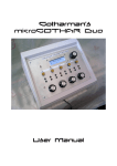
Object Manager (screenshot shown in Figure 1) is a model development environment
for writing COOML, which includes syntax checking and several other tools. GAME
(shown in Figure 2) is a program for running scenarios written in COOML. GCAM,
through GAME, provides a graphical display of maps and graphs, which can give visual
insights into an operation being studied. Results from GCAM can provide answers to
questions regarding, for example, consumption of resources, time delays and surveillance
of choke points. Case Launcher is a program for running a scenario multiple times in batchprocessing mode. Random number generators in GCAM allow examination of complex
probability distributions in a Monte Carlo fashion, particularly when using Case Launcher.
In defining a GCAM model, there are four main concepts that need to be understood:
maps; units; statistics, conditions and triggers; and phases.
2.1
Maps
GAME’s main visual presentation is a map of a geographic area on which the model
is displayed. The underlying map has no impact on the running of the model, except that
its associated x-y coordinate system defines where units are positioned on it. There can
be multiple maps defined for the model, Figure 2 shows a simulation with two maps, the
left one showing a macro view of the campaign and the right one showing a closer view of
the entities involved in the operation. Any 256-colour bitmap can be used as a map.
2.2
Units
Every entity defined in a GCAM scenario is a unit. Units might be: locations, like
cities or bases; military platforms, like ships or infantry units; or simple graphical displays,
like clocks or markers. They are shown on maps in GAME as icons (known as sprites) that
can be changed during a simulation, which could be used to indicate damage or readiness
for example. Units have properties associated with them that define things such as their
position, status, inventories and damage. For example, units can have a status of DEAF
(meaning they cannot hear or receive orders), BLIND (cannot see other units) or DEAD,
amongst others. Several of the properties are phase-controlled, meaning that they can be
changed during a simulation. Phases are discussed in Section 2.4. The most important of
these is the orders phaselist that tells the unit its status, how it is displayed and how it
will move.
2
DSTO–GD–0591
Figure 1: The ObjectManager environment.
Figure 2: The GAME environment, showing two maps with action overlaid on them and
a graph.
3
DSTO–GD–0591
2.3
Statistics, conditions and triggers
Statistics, conditions and triggers provide the mechanism to execute logical statements
in GCAM. They are used primarily in defining the behaviour of the units. There are
examples of their usage as part of the tutorial in Section 3.7. Statistics, conditions and
triggers are defined in a trigger file.
2.3.1
Statistics
A statistic is an expression that evaluates to a number. In COOML they are defined
in the Trigger file by commands of the form
statistic name = expression;
where statistic is the required keyword, name is the name of the statistic and expression
is the expression evaluating to a number. A statistic can be an integer, a real number
or a boolean, and may be scalar, vector or a table. Statistics may be the numerical
result of a mathematical expression or a property of the simulation evaluated through
an inbuilt function. Statistics are only evaluated for each time step that they are used
in a calculation1 ; if statistics are not required for a step they are left undefined. This
means statistics are not the same as variables in the usual programming sense because
they cannot store values between simulation time-steps2 .
2.3.2
Conditions
A condition is a Boolean or logical operation that compares two statistics over a specified number of turns, and evaluates to TRUE or FALSE. Like statistics, conditions are defined
in the trigger file by a command of the form
condition name = statistic1 operator statistic2;
where condition is the required keyword, name is the name of the condition, statistic1
and statistic2 are the two statistics being compared, and operator is the relational
operator between them (for example <, > or =).
2.3.3
Triggers
A trigger is a combination of conditions and other triggers, joined by logical operators
(for example & and |), that also evaluate to TRUE or FALSE. They are the basis for all
unit actions, such as phase transitions, inventory changes and damage events, as well as
simulation controls, such as event stops and the end of simulation. As with statistics and
conditions, triggers are defined in the trigger file by a command of the form
1
A statistic can be forced to be evaluated every turn by putting a modifier in front of the declaration
statement, but that is beyond the scope of this document.
2
Queues can be used for this, see Section 4.1.4.
4
DSTO–GD–0591
trigger name = operand1 operator operand2 operator ...;
where trigger is the required keyword, name is the name of the trigger, operand1 and
operand2 are the two conditions or triggers being compared, and operator is the logical
operator. There can be any number of operands separated by operators.
2.4
Phases and phaselists
A phase is a mode of operation that one of a unit’s phase-controlled properties assumes
until an associated trigger becomes TRUE, causing the phase to change. Each phase has
a name, attributes, and may have one or more phase change triggers. A phaselist links
multiple phases and defines an initial phase for each type of phase-controlled properties.
There are nine phase-controlled properties:
• orders – to define the movement, status and display image of a unit
• sensors – to turn sensors on and off
• sensor vulnerabilities – to define the sensor that can detect a unit
• command authority – to define the other units a unit has command over
• explicit orders to issue – to allow unit to give orders to the other units they have
command over
• altitude – to control the altitude display layer
• force membership – to define the force a unit is in, for example Red or Blue forces
• reporting chain – to define with which other units a unit shares its contacts
• posture – to define areas and shapes around a unit for display purposes.
The orders phaselist, for example, is defined using commands of the form
phase name { status string, sprite index, movement specification
? trigger - phase name2,... },
...,
~first phase;
where phase name is the name of the phase, status string defines the unit’s status,
sprite index defines which of the unit’s sprites to display for the phase, and movement
specification is a list of comma separated arguments that tell the unit how to move
in the phase. The ? and ~ are part of the COOML syntax used to indicate to GCAM
the parts of the command that follow them; a trigger follows a question mark and the
first phase follows a tilde. After the ?, trigger is the name of a trigger that, when TRUE,
will cause the phase to change to the phase called phase name2. There can be as many
trigger-phase name pairs as necessary. The phaselist may have any number of phases, with
the one to be used first defined by first phase and preceded by a ~. Examples of orders
phaselists can be seen in the tutorial in Section 3.7. Other phaselists are defined slightly
differently.
5
DSTO–GD–0591
3
Example scenario tutorial
To demonstrate the general usage of GCAM, this section provides a brief step-bystep tutorial. In this tutorial a scenario is created that simulates a Blackhawk helicopter
transporting infantry troops from Townsville to Cairns. Throughout this section there is
a series of numbered steps necessary to build the scenario. The final code of the tutorial
is contained in Appendix A.
3.1
Opening ObjectManager
ObjectManager is the scenario development environment, as discussed in Section 2.
1. The first step in creating a scenario is to open ObjectManager, which can be
done via the icon on the Windows start menu as shown in Figure 3.
Figure 3: The ObjectManager icon on the start menu.
2. To create a new scenario, at the initial dialog (shown in Figure 4) select the
option Create New File, select Master File from the drop down menu and click
OK. This will give you a new master file template to begin a scenario.
In ObjectManager, help on COOML or ObjectManager itself is available via the help
button on the tools toolbar (shown in figure 5), by pressing F1 or through the help menu.
3.2
Master file
The master file template contains code for every parameter that can be set, this is
much more than we need, so at this stage it is best to comment out the whole file and
uncomment lines as they are required later in the tutorial.
3. Comment out every line of the master file by inserting the comment markers
“//” at the beginning of each. Multiple lines can be commented by selecting
them and clicking the comment button on the edit toolbar, shown in Figure 6.
4. Save the new master file as tutorial.mst.
5. Uncomment the lines #MASTER and #END at the beginning and end of the file.
These lines define this as the master file and nothing will work without these.
6
DSTO–GD–0591
Figure 4: The initial dialog.
GAME
Help
Figure 5: GAME launcher and help icons on the tools toolbar.
6. Uncomment the line beginning with title and change it to
title = tutorial;
to give this scenario a title.
3.3
Map
The scenario needs a map to show units on, so at least one map needs to be registered
in the master file. This scenario requires a map of Australia, so the northern Australia
map that comes with GCAM will be used.
7. Uncomment the line in the master file beginning with maps and change it to
maps = Australia(C:\GCAM\SCENES\Ausmap.bmp,110,-23.5,155,-8);
A full explanation of the map parameter can be found in the COOML User’s Manual [6,
p. 3-3], but in this instance the command specifies:
7
DSTO–GD–0591
Comment
Syntax checker
Figure 6: The comment and syntax check buttons on the edit toolbar.
(155◦ E, 8◦ S)
(110◦ E, 23.5◦S)
Figure 7: The scenario map with the coordinates of the lower left and upper right corners
marked.
• Australia is the name of the map;
• Ausmap.bmp is the 256 colour bitmap of the map shown in Figure 7;
• and the numbers represent the lower left x-coordinate, lower left y-coordinate, upper
right x-coordinate and upper right y-coordinate respectively, which in this case are
latitude and longitude, but could be any system that can be represented in Cartesian
coordinates.
3.4
Sprites
A sprite is an icon used to display the location and state of a unit on the background
map. Sprites must be registered in the master file before they can be referenced in a unit
file by the units that use them. We will now create three sprites, for the Blackhawk, an
infantry division and key locations in the scenario.
8. Register the Blackhawk sprite in the master file, by uncommenting the line
beginning with sprite registrations and changing it to:
sprite registrations =
blackhawk(C:\GCAM\SPRITES\ah1.bmp,4,18,11,1,FALSE,TRUE);
As with the map registration parameter a full explanation of the command can be found
in the COOML User’s Manual [6, p. 3-6], but in this case the parameter specifies:
• blackhawk as the sprite’s name for later reference in using it for a unit;
• ah1.dib as the filename of the bitmap shown in Figure 8;
8
DSTO–GD–0591
Figure 8: The Blackhawk helicopter’s sprite with four views (from top to bottom: normal,
detected, killed, blank).
• 4 as the number of views that the sprite contains,
• (18,11) is the offset, that is the location of the hot spot of the image relative to the
top left corner of the image (this point defines where the sprite is placed on the map
and the point that sprite pivots on when it rotates);
• 1 is the initial zoom factor (how big the sprite appear on the map);
• FALSE tells GAME not to make the sprite larger as a user zooms in on the map;
• TRUE tells GAME to rotate the sprite with the heading of the unit.
9. Register the other two sprites, for infantry and key locations, by further changing
the line to
sprite registrations =
blackhawk(C:\GCAM\SPRITES\ah1.bmp,4,18,11,1,FALSE,TRUE),
infantry(C:\GCAM\SPRITES\infdv2.dib,4,18,11,1,FALSE,TRUE),
redspot(C:\GCAM\SPRITES\mine.dib,4,8,6,4,TRUE,FALSE);
A generic red spot is used to indicate the key locations.
3.5
Units
We will now create units for the Blackhawk, some infantry and two locations. Units
are defined in unit files, separate from the master file. A unit requires at least an identifier
(unique integer value), a sprite for visual representation, and an initial position.
10. Create a unit file by clicking on the UNT button on the templates toolbar (shown
in Figure 9). As with the master file, comment out all of the code and save it
as tutorial.unt.
11. To make this new file part of the scenario it needs to be referenced in the master
file by uncommenting the unit files line and changing it to
unit files = tutorial.unt;
9
DSTO–GD–0591
Trigger
Master
Unit class
Unit
Output
control
Sensor
Display
Graph
control
Map view
overlay
Figure 9: The templates toolbar with each of the buttons labelled.
12. To begin creating units, uncomment the #UNIT and #END lines in the unit file.
13. Every unit needs a unique integer identifier and a name, so uncomment the id
line and change it to
id = 101;
and uncomment and change the label line to
label = blackhawk;
14. For the unit to be displayed on the map, it needs a sprite. Uncomment the
display style and sprite lines and change them to
display style = SPRITE;
and
sprite = blackhawk;
this associates the unit with the Blackhawk sprite defined in the master file.
15. The sprite index0 line can be uncommented and changed to
sprite index0 = 0;
however this is the default index, so it is not required.
16. The unit also needs an initial position, so uncomment the x0 and y0 lines and
change them to
x0 = 145.77;
for longitude and
y0 = -16.92;
for latitude. The coordinates are in latitude and longitude in this case because
that was the system used when specifying the corners of the map in the master
file.
We will now create the other three units in this scenario by inserting similar code for each
one.
10
DSTO–GD–0591
17. Insert this code for the infantry
#UNIT
id=102;
label=squad;
display style = SPRITE;
sprite = infantry;
sprite index0 = 0;
sprite rotates = FALSE;
x0 = 147.82;
y0 = -19.26;
#END
18. Insert this code create a unit for Townsville
#UNIT
id = 001;
label = Townsville;
display style = SPRITE;
sprite = redspot;
sprite index0 = 1;
x0 = 147.82;
y0 = -19.26;
#END
19. Insert this code for Cairns
#UNIT
id = 002;
label = Cairns;
display style = SPRITE;
sprite = redspot;
sprite index0 = 1;
x0 = 145.77;
y0 = -16.92;
#END
3.6
Running in GAME
At this stage there is enough of the model defined for it to be able to run in GAME.
First, some checks should be made.
20. Make sure all of the scenario files are referenced in the master file and are
available. In particular, in a fresh GCAM installation the map and sprite images
in C:\GCAM\MAPS and C:\GCAM\SPRITES are contained in zip files and need to
be extracted to be used.
21. Use the syntax checker in ObjectManager to check for errors in newly entered
code, and fix errors as they arise. The syntax checker can be started via the
button on the edit toolbar, shown in Figure 6.
11
DSTO–GD–0591
22. Save all the code and switch to GAME using the GAME button in Object
Manager, shown in Figure 5, to see if the verified code will load and execute as
expected.
23. In GAME you will be presented with a blank window. To show the map, select
Views → Map View from the menu.
24. To make GAME always bring up the map when it is started, select Window →
Save Workspace from the menu in GAME, save the workspace as tutorial.wsp
and back in ObjectManager uncomment the initial workspace line in the
master file and changing it to
initial workspace = tutorial.wsp;
25. To run the scenario, left click on the map. This will set the timer at the bottom
of the window running. The speed of the run can be slowed down by selecting
Control → Timing from the menu and entering the minimum amount of time (in
milliseconds) that each timestep will last. The greater the number, the slower
the run. Alternatively, the scenario can be run one time step at a time by right
clicking on the map.
At this stage, GAME should show all four units in their initial positions. There is no
movement on the map at this stage as no behaviour has been defined for the units.
3.7
Defining behaviour
To define a unit’s behaviour, at least one phaselist or some independently triggered
actions, such as inventory control and damage recovery, are required. Unit control also
requires some statistics, conditions and triggers to be defined, these are written in a Trigger
file.
26. We need to create a trigger file from the template by clicking the TRG button
on the templates toolbar (shown on Figure 9). This template only contains a
#TRIGGERS and an #END statement. Save this file as tutorial.trg.
27. As with the unit file, to make the trigger file part of the scenario it needs to
be referenced in the master file by uncommenting the trigger files line and
changing it to
trigger files = tutorial.trg;
In GCAM, time is in units of turns, defined by time per turn in the master file, and
distance is in the units used in maps in the master file, which in this case is degrees. We
need statistics that turn these units into more useful ones for later use.
12
DSTO–GD–0591
28. To convert turns into seconds, minutes and hours add the lines
statistic second = 1/SECONDS PER TURN;
statistic minute = 60*second;
statistic hour = 60*minute;
and to convert from degrees to nautical miles add the line
statistic nm = 1/60;
We can also add knots as a unit for speed by inserting
statistic kt = nm/hour;
With the kt statistic, we can add statistics for the speed of the Blackhawk and
the infantry that will be required later
statistic blackhawk_speed = 100*kt;
statistic squad_speed = 10000000;
Some triggers will need to be created to cause actions to occur in the simulation. This is
also done in the trigger file. To begin with, two triggers will be defined.
29. Add the first trigger by inserting,
trigger Always = TRUE;
which is always true, and the second,
trigger blackhawk_at_townsville=[ATTACHED(blackhawk,Townsville)];
that uses the inbuilt function ATTACHED that is only true when the Blackhawk
is at Townsville.
Once some statistics, conditions and triggers have been defined, an orders phaselist can
be added to the Blackhawk unit definition in the unit file. The structure of the orders
phaselist is shown in Section 2.4.
30. To give the Blackhawk its first orders, uncomment the orders line and replace
it with
orders = init{CLEAR, 0, ATTACH, blackhawk_speed, Cairns
? Always - flytotownsville},
flytotownsville{no change, 0, ATTACH, blackhawk_speed,
Townsville},
~init;
This contains two orders phases. The first phase initialises the Blackhawk by setting its
status to CLEAR, its sprite to index 0 and its movement to ATTACH to Cairns at speed
blackhawk_speed. After the ?, the trigger Always is set, so after the first turn of the
simulation the orders phase will change to flytotownsville. The second phase does not
change the status or sprite, but makes the Blackhawk move from Cairns to Townsville at
blackhawk_speed and attach to it when it gets there. The ~init part simply defines the
init orders to be those used first. Running the simulation now should show the Blackhawk
starting at Cairns and moving to Townsville.
13
DSTO–GD–0591
31. Next, add an orders phase to make the Blackhawk wait for a period of time in
Townsville. Change the flytotownsville orders phase to
flytotownsville{no change, 0, ATTACH, blackhawk_speed,
Townsville ? blackhawk_at_townsville - wait},
which adds a trigger to the new wait phase, then insert the new wait phase,
wait{no change, 0, ATTACH, blackhawk_speed, Townsville
? waited - flytocairns},
between the last orders phase and ~init.
This tells the Blackhawk to attach to Townsville, but as the Blackhawk has already done
this in the previous phase no movement will occur. The trigger waited used in this phase
causes a number of turns to elapse before the next phase is started. This trigger has not
yet been defined, but is created in the next step.
32. In the trigger file insert
condition waiting = [ORDERS(blackhawk, wait)];
trigger waited = waiting & [TURNS IN PHASE(blackhawk,ORDERS)
>= 1*hour];
The first condition uses the inbuilt ORDERS function to determine whether the Blackhawk
is in the wait orders phase. The trigger is then true if the Blackhawk is in the wait phase
and has been in that phase for the number of turns in an hour. In other words, after the
Blackhawk has waited an hour it will move on to the next phase, flytocairns, which is
defined in the next step.
33. The final orders phase required for the Blackhawk is
flytocairns{no change, 0, ATTACH, blackhawk_speed, Cairns
? blackhawk_at_cairns - flytotownsville},
This is the same as the flytotownsville phase, except it causes the Blackhawk
to fly in the opposite direction. The trigger for this phase needs be defined in
the trigger file as,
trigger blackhawk_at_cairns = [ATTACHED(blackhawk,Cairns)];
which is the equivalent of blackhawk_at_townsville.
Running the scenario now will cause the Blackhawk to move backwards and forwards
between Cairns and Townsville, waiting for an hour at Townsville. The movement of the
units will probably be extremely fast on the screen when run at full speed and it may be
worth slowing the run down as described at the end of Section 3.6.
14
DSTO–GD–0591
34. The infantry start in Townsville, get on the Blackhawk when it arrives and get
off in Cairns. So, for the infantry, insert the orders phases
orders = init{CLEAR, 0, ATTACH, squad_speed, Townsville
? squad_to_blackhawk - onblackhawk},
onblackhawk{no change, 0, ATTACH, squad_speed, blackhawk
? blackhawk_at_cairns - offblackhawk},
offblackhawk{no change, 0, ATTACH, squad_speed, Cairns},
~init;
35. In the trigger file, define the trigger squad_to_blackhawk as
trigger squad_to_blackhawk = [ATTACHED(blackhawk,Townsville)]
& [ATTACHED(squad,Townsville)];
which is true when both the Blackhawk and the infantry are both attached to
Townsville.
To summarise the infantry’s orders phases, the first phase, init, initialises the unit with
a CLEAR status. The second phase of orders tells the infantry to attach to the Blackhawk.
So, when the infantry and the Blackhawk are both in Townsville, the infantry will get on
the Blackhawk. When the infantry are attached to the Blackhawk they will move with it,
so the Blackhawk moves back to Cairns the infantry go to Cairns as well. The third and
final orders phase, triggered by the Blackhawk attaching to Cairns, causes the infantry to
get off the Blackhawk and attach to Cairns.
Running the simulation now will show the Blackhawk starting at Cairns, moving to
Townsville, waiting there for an hour and then moving back to Cairns with the infantry.
The Blackhawk will then fly between Cairns and Townsville without the infantry. The
simple scenario is now complete.
4
Other elements of GCAM
GCAM has many other features not discussed so far. For example, there are several
movement specifications in addition to ATTACH. These functions are not covered in this
basic introduction, but can be explored through the user’s manuals and help files. An
overview of some of these features is given in this section to bring them to your attention
for further investigation.
4.1
Unit file parameters
Most GCAM functions are available through the unit files and some of the more important ones, movement specifications, inventories, damage/repair and queues, are outlined
here.
15
DSTO–GD–0591
4.1.1
Movement specifications
There are 22 different types of movement that are able to be given to units through the
orders phaselist. These are detailed on pages 10-7 to 10-19 of the COOML User’s Manual
[6]. Movement specifications are available to make units move along a path, search an area,
move randomly, and move relative to other units. One example is the ladder search, where
an area to be searched and some parameters are specified, and GCAM then calculates a
ladder pattern path for the unit to move along.
4.1.2
Inventories
Units can have inventories associated with them. Inventories are manipulated through
triggered events, including transfers to other units, production, consumption and changes
in capacity. For example, the Blackhawk in the tutorial could have a fuel inventory that
is consumed as the Blackhawk moves and replenished (or produced) when the Blackhawk
is at its base. Inventories are documented on page 10-28 of the COOML User’s Manual
[6].
4.1.3
Damage/repair
Damage can be inflicted and repair made to the units. Each of a unit’s systems, that
are defined through the systems parameter, have a health value ranging from 0 to 1.
Events can be triggered to increase or decrease the health through the system damage
events parameter. The obvious use for this is in simulating weapons. In that case an
attacking unit might have a system damage event that was triggered when it moved close
to an enemy unit that reduced the enemies health on all systems by some random factor.
Damage and repair is covered on page 10-33 of the COOML User’s Manual [6].
4.1.4
Queues
Queues provide the only mechanism in GCAM for storing data between simulation
turns. A queue is an ordered set of numbers associated with a unit. Queues are described
on page 10-33 of the COOML User’s Manual [6].
4.2
Other files
In addition the master, trigger and unit files, there are several other file types adding
functions to GCAM. These are sensor, unit class, output control, graph control, display
and mapview overlay files.
4.2.1
Sensor
Sensors are required by units in order for them to detect or see others. Sensors are
defined in sensor files (.sen). They also need to be specified in the unit files of the units
16
DSTO–GD–0591
that carry them and the units that are vulnerable to them. Sensors can be set with
custom detection areas and probabilities of correctly detecting certain units and their
characteristics, such as force membership. A full description of the sensor file is covered
in Section 6 of the COOML User’s Manual [6].
As an example, in the tutorial, the Blackhawk could have a sensor defined by
#SENSOR
id = 100;
label = blackhawk_radar;
range = [5*nm];
#END
This simplest way to define a sensor only specifying the id, label and range. In the
Blackhawk’s unit definition the line
sensors = on{blackhawk_radar};
needs to be added. If the Blackhawk can detect the infantry then the infantry’s unit
definition needs the line
sensor vulnerabilities = on{blackhawk_radar};
Both the sensor and sensor vulnerabilities parameters are phaselists, so they can be
set to change during a simulation, like the orders phaselist in the tutorial. To view the
area that the sensors can see in GAME, select MapView → MapView Properties. On the
window that appears, select the Overlay tab, check the Sensors box, then click Apply and
Done. The sensor area will then be shown on the map as a blue outline.
4.2.2
Unit class
Unit parent classes can be defined in unit class files (.ucl). This allows units of
similar type to be defined more efficiently by referencing a parent class. Units inherit
all the parameters defined in their parent class, but parameters defined in the unit file
supersede the parent definition. The exception to this is when += is used in phaselist
definitions, rather than =. In that case the phases are added to those already defined in
the parent class. Multiple levels of inheritance are allowed, so a parent class can itself
have a parent class. As an example, if there were several Blackhawks in the tutorial, a
parent class for all Blackhawks could be defined as
#UNITCLASS
class name = blackhawk;
display style = SPRITE;
sprite = blackhawk;
x0 = 147.2;
y0 = -6.6;
orders = init{CLEAR, 0, ATTACH, blackhawk_speed, Cairns
17
DSTO–GD–0591
? Always - flytotownsville},
flytotownsville{no change, 0, ATTACH, blackhawk_speed, Townsville
? blackhawk_at_townsville - wait},
wait{no change, 0, ATTACH, blackhawk_speed, Townsville
? waited - flytocairns},
flytocairns{no change, 0, ATTACH, blackhawk_speed, Cairns
? blackhawk_at_cairns - flytotownsville},
~init;
#END
with each Blackhawk then defined in the unit file as
#UNIT
id = 103;
name = blackhawk3;
parent class = blackhawk;
#END
#UNIT
id = 104;
name = blackhawk4;
parent class = blackhawk;
#END
The unit class files are covered in Section 11 of the COOML User’s Manual [6].
4.2.3
Output control
The output control file (.ctl) defines the statistics to be written to a nominated output
file. This is the primary method of extracting data from GCAM for further analysis. The
output is in tab separated variable format that is able to be read by Excel [5]. The output
control file is covered in Section 7 of the COOML User’s Manual [6].
4.2.4
Graph control
The graph control file (.grf) allows graphs of the values of statistics to plotted in
GAME. For example, a graph of the amount of fuel at a location against time is shown in
Figure 2. The graph control file is covered in Section 8 of the COOML User’s Manual [6].
4.2.5
Display
The display file (.dis) allows text or video to be displayed in the GAME window (not
on the maps). For example, the current simulation time could be shown. The display file
is covered in Section 9 of the COOML User’s Manual [6].
18
DSTO–GD–0591
4.2.6
Mapview overlay
Through the mapview overlay file (.mvo) text and shapes can be overlaid onto the
maps in GAME. For example, a label could be attached to a unit. The mapview overlay
file is covered in Section 12 of the COOML User’s Manual [6].
5
Further guidance
There are several resources that could be consulted in conjunction with this document
on the JOD Wiki (http://jodwiki.dsto.defence.gov.au/display/joa/GCAM). These
are:
• Training Material (August 1998) PowerPoint files:
– GCAM Introduction – History
– GCAM Introductory Education Course – Day 1
– GCAM Fundamentals of COOML
– GCAM Introductory Education Course – GAME Execution
• DOAS 2000 Presentation on GCAM (Version 2.5) by Glenn Moy and Greg Searle.
• The US Marine Corps document “Modeling and Simulation” that accompanies the
Non-combatant Evacuation Operation (NEO) GCAM scenario.
• Sample scenarios located in the samples directory of the GCAM installation
6
Summary
This document is intended as a basic introduction to GCAM. Once an analyst has completed some relatively simple scenarios, such as the one detailed in the tutorial, the scope
of work needed to address larger issues should become clearer. The value of constructing a
conceptual model of the operational missions to be studied and of planning before jumping
into coding is important to appreciate. After this introduction, the next step would be to
experiment in developing more complex scenarios by consulting the resources specified in
the introduction, especially the GCAM User’s Manual [6] and GCAM’s help files.
References
1. General Campaign Analysis Model (GCAM) [computer program]. Version 3.3. Washington, DC: Systems Planning and Analysis, Inc. (SPA); 2003.
2. Java Standard Edition 6 [computer program]. Version 1.6.0. Santa Clara, California:
Sun Microsystems, Inc.; 2006.
19
DSTO–GD–0591
3. Integrated Theater Engagement Model (ITEM) [computer program]. Version 8.3. San
Diego, California: Science Applications International Corporation (SAIC); 1999.
4. Joint Integrated Contingency Model (JICM) [computer program]. Version 3.5. Santa
Monica, California: RAND Corporation; 1999.
5. Microsoft Office Excel [computer program]. Version 11. Redmond, Washington: Microsoft Corp.; 2003.
6. Conditional Object Oriented Meta-Language (COOML) User’s Manual Version 3.3.
Washington, DC: Systems Planning and Analysis, Inc.; 2003.
20
DSTO–GD–0591
Appendix A
Tutorial code
This appendix contains the code generated by completing the tutorial in Section 3.
A.1
Master file
#MASTER
//
title = Tutorial;
//
////files
// include files = ;
trigger files = tutorial.trg;
// unit class files = ;
unit files = tutorial.unt;
// sensor files = ;
// output control files = ;
// graph control files = ;
// display files = ;
// mapview overlay files = ;
//
////coordinate system and map definition
time per turn = 1 SECONDS; // SECONDS, MINUTES, HOURS, DAYS
maps = Australia(C:\GCAM\SCENES\Ausmap.bmp,-23.5,110,-8,155);
//map name(map file, X LL, Y LL, X UR Y UR), ...
////sprite display control
sprite registrations =
blackhawk(C:\GCAM\SPRITES\ah1.bmp,4,18,11,1,FALSE,TRUE),
infantry(C:\GCAM\SPRITES\infdv2.dib,4,18,11,1,FALSE,TRUE),
redspot(C:\GCAM\SPRITES\mine.dib,4,8,6,4,TRUE,FALSE);
//name(path, number of images, x offset, y offset,
// initial zoom factor, zoom with background flag,
// sprite rotates), ...
// contact perception mapping = ; //MUR group(sprite name,
// STATUS QUERY - sprite image index, UNKNOWN -0), ...
// posture styles = ; //posture name(posture id, fill, color), ...
//
// automated event display control =
//
MOVEMENT(UNFILLED,BLACK),// paths and movement polygons
//
SENSORS(UNFILLED,BLUE),// sensor footprints
//
REPAIR(FILLED,GREEN),// repair agent (if any),
// connecting line (if required), receiver
//
INVENTORY(FILLED,MONEYGREEN),// source, connecting line, receiver
//
QUEUES(FILLED,SKYBLUE),// source, connecting line, receiver
//
CONTACT REPORTING(FILLED,CYAN),// source, connecting line, receiver
//
COMMANDS(FILLED,MEDIUMGRAY),// commander, connecting line, receiver
21
DSTO–GD–0591
//
//
//
CONTACT LISTS(FILLED,DARK YELLOW),// source, connecting line,
// receiver
DETECTIONS(FILLED,MAGENTA),// detecting unit, connecting line,
// detected unit
DAMAGE(FILLED,RED); // attacker (if any),
// connecting line (if required), receiver
//
////unit report display control
// unit classification hierarchy = ;
// force membership hierarchy = ;
// build event logs = FALSE; //TRUE or FALSE
// inventory report labels = ;
// display fixed digits = ;
// display zero threshold = ;
//
////GAME window display control
initial workspace = tutorial.wsp;
// workspace changes = ; //trigger name(workspace filename), ...
// disable mouse start stop = FALSE; //TRUE or FALSE
//
////simulation control
// seed = ;
// first turn number = ;
// end trigger = ;
// number of simulations = ;
// event stop triggers = ;
// evaluation order = EXPLICIT ORDERS GENERATION, FORCE MEMBERSHIP,
//
SENSOR MANAGEMENT, REPORTING CHAIN CHANGES,
//
CONTACT LIST GENERATION, MOTION, POSTURE, DAMAGE AND REPAIR,
//
INVENTORY MANIPULATIONS, QUEUE MANIPULATIONS;
// unit evaluation order control = DEFAULT;
//DEFAULT, FORWARD, REVERSE, RANDOM
// warnings = NORMAL; //ERRORS, IGNORE
// contact merging technique = AVERAGE INFORMATION; //or LEAST ERROR
//
////registered items
// registered inventory class names = ;
// class name (identifier, D or C), ...
// registered system names = ; //system name(numeric identifier), ...
// registered queue names = ; //queue name(numeric identifier), ...
// registered text style names = ;
//name (FONT(fontname, color, size, bold, italic),
// BKCOLOR(color) ), ...
// registered drawing style names = ;
//name (PEN(color, size, pen style),BRUSH(color, brush style),
// BKCOLOR(color) ), ...
//
22
DSTO–GD–0591
////output control
// output prefix = ; //Prefix
// output selections = ; //EVENTS, DAMAGE, or INVENTORY
// event log = ; //File name and path
// damage log = ; //File name and path
// inventory log = ; //File name and path
// output events after turn = ; //Turn number
// output damage after turn = ; //Turn number
// output inventory after turn = ; //Integer
// output final damage = ; //TRUE or FALSE
// output final inventory = ; //TRUE or FALSE
// damage output frequency = ; //Integer
// inventory output frequency = ; //Integer
//
//
#END
A.2
Trigger file
#TRIGGERS
trigger Always = TRUE;
statistic second = 1/SECONDS PER TURN;
statistic minute = 60*second;
statistic hour = 60*minute;
statistic nm = 1/60;
statistic kt = nm/hour;
statistic blackhawk_speed = 100*kt;
statistic squad_speed = 10000000;
trigger blackhawk_at_cairns = [ATTACHED(blackhawk,Cairns)];
trigger blackhawk_at_townsville = [ATTACHED(blackhawk,Townsville)];
trigger squad_to_blackhawk = [ATTACHED(blackhawk,Townsville)]
& [ATTACHED(squad,Townsville)];
condition waiting = [ORDERS(blackhawk, wait)];
trigger waited = waiting & [TURNS IN PHASE(blackhawk,ORDERS) >= 1*hour];
#END
23
DSTO–GD–0591
A.3
Unit file
#UNIT
id=102;
label=squad;
display style = SPRITE;
sprite = infantry;
sprite index0 = 0;
sprite rotates = FALSE;
x0 = 147.82;
y0 = -19.26;
orders = init{CLEAR, 0, ATTACH, squad_speed, Townsville
? squad_to_blackhawk - onblackhawk},
onblackhawk{no change, 0, ATTACH, squad_speed, blackhawk
? blackhawk_at_cairns - offblackhawk},
offblackhawk{no change, 0, ATTACH, squad_speed, Cairns},
~init;
#END
#UNIT
id = 001;
label = Townsville;
display style = SPRITE;
sprite = redspot;
sprite index0 = 1;
x0 = 147.82;
y0 = -19.26;
#END
#UNIT
id = 002;
label = Cairns;
display style = SPRITE;
sprite = redspot;
sprite index0 = 1;
x0 = 145.77;
y0 = -16.92;
#END
#UNIT
//
id = 101;
label = blackhawk;
//
// parent class = ;
//
24
DSTO–GD–0591
display style = SPRITE; //SPRITE or NEVER DISPLAY
sprite = blackhawk;
// sprite index0 = ;
// sprite text = ;
// sprite rotates = ; //TRUE or FALSE
x0 = 145.77;
y0 = -16.92;
// h0 = ;
// z0 = ;
//
// altitude = ;
//phase name{ altitude value ? trigger - phase name,... },
// ..., ~first phase;
//
// command authority = ;
//phase name{ units ? trigger - phase name,... },
// ..., ~first phase;
// command processing delay = ;
// explicit orders to issue = ;
//phase name{ phase names ? trigger - phase name,... },
// ..., ~first phase;
//
// force membership = ;
//phase name{ force membership ? trigger - phase name,... },
// ..., ~first phase;
// classification = ;
//
// sensors = ;
//phase name{ sensors : contact hold time
// ? trigger - phase name,... }, ..., ~first phase;
// sensor vulnerabilities = ;
//phase name{ sensors ? trigger - phase name,... }, ..., ~first phase;
// refresh contacts prevention trigger = ;
// refresh contacts trigger = ;
// reporting chain = ;
//phase name{ units ? trigger - phase name,... }, ..., ~first phase;
// contact report processing delay = ;
//
orders = init{CLEAR, 0, ATTACH, blackhawk_speed, Cairns
? Always - flytotownsville},
flytotownsville{no change, 0, ATTACH, blackhawk_speed, Townsville
? blackhawk_at_townsville - wait},
wait{no change, 0, ATTACH, blackhawk_speed, Townsville
? waited - flytocairns},
flytocairns{no change, 0, ATTACH, blackhawk_speed, Cairns
? blackhawk_at_cairns - flytotownsville},
~init;
25
DSTO–GD–0591
//phase name { status string, sprite index, movement specification
// ? trigger - phase name,... }, ..., ~first phase;
//
// posture = ;
//phase name{ posture style, polygon ? trigger - phase name,... },
// ..., ~first phase;
//
// systems = ;
//system name(initial operational capability, health threshold)
// dead trigger = ;
// damage control suppression = ;
// system damage events = ;
//trigger(damage style(damage calculation parameters), system id,
// unit id)
//
// inventories = ;
//name(initial inventory, inventory capacities,
// inventory minimum capacities, inventory counting method)
// inventory control suppression = ;
// inventory events = ;
// trigger (trading partner, inventory class to trade,
// inventory change, inventory capacity change), ...;
//
// queues = ; //queue name (queue initial values)
// queue control suppression = ;
// queue events = ;
// trigger action name (action parameters), unit ref), ...;
//
// output label = ;
// output selections = ; //EVENTS, DAMAGE, INVENTORY, QUEUES, or CONTACTS
// output events after turn = ;
// output contacts after turn = ;
//
// output damage after turn = ;
// output inventory after turn = ;
// output queues after turn = ;
// output final damage = ; //TRUE or FALSE
// output final inventory = ; //TRUE or FALSE
// output final queues = ; //TRUE or FALSE
// damage output frequency = ;
// inventory output frequency = ;
// queues output frequency = ;
// inventory report labels = ;
// queue display depth = ;
//
// automated event displays =
// MOVEMENT,
26
DSTO–GD–0591
//
//
//
//
//
//
//
//
//
//
//
SENSORS,
COMMANDS,
CONTACT REPORTING,
DETECTIONS,
CONTACT LISTS,
INVENTORY,//(ALL or list of classes)
QUEUES,//(ALL of list of queue names)
DAMAGE,//(ALL or list of systems)
REPAIR; //(ALL or list of systems)
evaluation order priority = ;
// constant, statistic, or embedded statistic.
// Larger values take on higher priority
//
//
#END
27
DISTRIBUTION LIST ∗
Introduction to the General Campaign Analysis Model (GCAM) Version 3.3
James Caunce, Greg Searle
AUSTRALIA
DEFENCE ORGANISATION
No. of Copies
Task Sponsor
Director General, Capability and Plans
1 Printed
S&T Program
Chief Defence Scientist
1
Chief, Projects and Requirements Division
1
Group Finance Officer
1
DG Science Strategy and Policy
1
Counsellor Defence Science, London
Doc Data Sheet
Counsellor Defence Science, Washington
Doc Data Sheet
Scientific Adviser to MRDC, Thailand
Doc Data Sheet
Scientific Adviser Intelligence and Information
1
Navy Scientific Adviser
1
Scientific Adviser - Army
1
Air Force Scientific Adviser
1
Scientific Adviser to the DMO
1
Deputy Chief Defence Scientist Platform and Human Systems
Task Leader, Capability Planning Analysis
Doc Data Sht &
Exec Summary
Doc Data Sht &
Dist List
Doc Data Sht &
Dist List
1
Discipline Head, Joint Modelling, Simulation & Experimentation
1
Science Team Leader (Anthony Ween)
1
Author(s): James Caunce, Greg Searle
4 Printed
Chief of Joint Operations Division
Research Leader, Future Operations
DSTO Library and Archives
Library Fishermans Bend
Doc Data Sheet
Library Edinburgh
1 Printed
Library, Sydney
Doc Data Sheet
Library, Stirling
Doc Data Sheet
Library Canberra
1 Printed
Capability Development Executive
Director General Maritime Development
Doc Data Sheet
Director NCW Development
Doc Data Sheet
Assistant Secretary Investment Analysis
Doc Data Sheet
Chief Information Officer Group
DICTF
Doc Data Sheet
Strategy Executive
Assistant Secretary Strategic Planning
Policy Officer, Counter–Terrorism and Domestic Security
Jon Longhurst, Deliberate Planning & Strategic Wargaming
Strategic Policy Division
Joint Logistics Command
Directorate of Ordnance Safety
Head Engineering Systems
Doc Data Sheet
Doc Data Sheet
Doc Data Sheet
1
Navy
Maritime Operational Analysis Centre, Building 89/90
Garden Island Sydney NSW
Deputy Director (Operations)
Deputy Director (Analysis)
Director General Navy Capability, Performance and Plans, Navy
Headquarters
Director General Navy Communications & Information Warfare
Doc Data Sheet
Director General Navy Health Services
Doc Data Sheet
Director General Navy Certification and Safety
Doc Data Sheet
Director General Navy People
Doc Data Sheet
Head Navy Engineering
Doc Data Sheet
Director General Maritime Operations
Doc Data Sheet
Commodore Training
Doc Data Sheet
Commander Surface Force
Doc Data Sheet
Commander Mine Warfare, Clearance Diving, Hydrographic,
Meteorological and Patrol Force
Commander Fleet Air Arm
Doc Data Sheet
Commander Submarine Force
Doc Data Sheet
Commodore Flotillas
Doc Data Sheet
Commodore Support
Doc Data Sheet
SO Science Fleet Headquarters
1
Doc Data Sht &
Dist List
Doc Data Sheet
Doc Data Sheet
Army
SO(Science) Forces Command
SO (Science) - Special Operations Command (SOCOMD)
Russell Offices Canberra
SO(Science) 1st Division
1
Doc Data Sht &
Exec Summary &
Dist List
Doc Data Sheet
Chief of Staff HQ 16Bde (Avn)
SO2 S&T FDG LWDC - (Staff Officer for Science and Technology,
Force Development Group)
SO(Science) 1Bde
Doc Data Sht &
Exec Summary &
Dist List
Doc Data Sheet
Doc Data Sheet
SO(Science) 3Bde
Doc Data Sheet
SO(Science) 17 CSS Bde
Doc Data Sheet
J86 (TCS GROUP), DJFHQ
Doc Data Sheet
Air Force
SO (Science) - Headquarters Air Combat Group, RAAF Base,
Williamtown NSW 2314
Staff Officer Science Surveillance and Response Group
SO (Science) Combat Support Group
Staff Officer Science HQ Air Lift Group
Doc Data Sht &
Exec Summary
Doc Data Sht &
Exec Summary
Doc Data Sht &
Exec Summary
Doc Data Sht &
Exec Summary &
Dist List
Joint Operations Command
Director Military Strategic Capability
Doc Data Sheet
SO Dev ADF Warfare Centre
Doc Data Sheet
Director General Strategic Logistics
Doc Data Sheet
Intelligence and Security Group
AS Transnational and Scientific Intelligence, DIO
Doc Data Sheet
Manager, Information Centre, Defence Intelligence Organisation
1
Director Advanced Capabilities, DIGO
Doc Data Sheet
Defence Materiel Organisation
CoS GM Systems
Doc Data Sheet
Program Manager Air Warfare Destroyer
Doc Data Sheet
Guided Weapon & Explosive Ordnance Branch (GWEO)
Doc Data Sheet
Director Engineering Operations; Land Engineering Agency
(Michael Yates)
CSIO
Doc Data Sheet
Deputy Director Joint Fuel & Lubricants Agency
Systems Engineering Manager
CBRNE Program Office, Land Systems Division
Doc Data Sheet
Doc Data Sheet
Doc Data Sheet
OTHER ORGANISATIONS
National Library of Australia
1
NASA (Canberra)
1
Library of New South Wales
1
UNIVERSITIES AND COLLEGES
Australian Defence Force Academy
Library
1
Head of Aerospace and Mechanical Engineering
1
Hargrave Library, Monash University
Doc Data Sheet
OUTSIDE AUSTRALIA
INTERNATIONAL DEFENCE INFORMATION CENTRES
US Defense Technical Information Center
1
UK Dstl Knowledge Services
1
Canada Defence Research Directorate R&D Knowledge & Information Management (DRDKIM)
NZ Defence Information Centre
1
1
ABSTRACTING AND INFORMATION ORGANISATIONS
Library, Chemical Abstracts Reference Service
1
Engineering Societies Library, US
1
Materials Information, Cambridge Scientific Abstracts, US
1
Documents Librarian, The Center for Research Libraries, US
1
International Technology and Science Center (ITSC) Library
1
INFORMATION EXCHANGE AGREEMENT PARTNERS
National Aerospace Laboratory, Japan
1
National Aerospace Laboratory, Netherlands
1
SPARES
4 Printed
Total number of copies: Printed: 11, PDF: 32
∗
In keeping with the DSTO Research Library’s Policy on Electronic distribution of official
series reports, unclassified, xxx–in confidence and restricted reports will be sent to recipients
via DRN email as per the distribution list. Authors, task sponsors, libraries and archives
will continue to receive hard copies.
Page classification: UNCLASSIFIED
DEFENCE SCIENCE AND TECHNOLOGY ORGANISATION
DOCUMENT CONTROL DATA
1. CAVEAT/PRIVACY MARKING
2. TITLE
3. SECURITY CLASSIFICATION
Introduction to the General Campaign Analysis
Model (GCAM) Version 3.3
Document
Title
Abstract
4. AUTHORS
5. CORPORATE AUTHOR
James Caunce, Greg Searle
Defence Science and Technology Organisation
DSTO Fern Hill,
Department of Defence, Canberra 2600, ACT
6a. DSTO NUMBER
6b. AR NUMBER
6c. TYPE OF REPORT
DSTO–GD–0591
AR 014–630
(U)
(U)
(U)
General Document
7. DOCUMENT DATE
September, 2009
8. FILE NUMBER
9. TASK NUMBER
10. SPONSOR
11. No OF PAGES
12. No OF REFS
2008/1074643/1
ADF 07/068
DGCP
28
6
13. URL OF ELECTRONIC VERSION
14. RELEASE AUTHORITY
http://www.dsto.defence.gov.au/corporate/
reports/DSTO–GD–0591.pdf
Chief, Joint Operations Division
15. SECONDARY RELEASE STATEMENT OF THIS DOCUMENT
Approved For Public Release
OVERSEAS ENQUIRIES OUTSIDE STATED LIMITATIONS SHOULD BE REFERRED THROUGH DOCUMENT EXCHANGE, PO BOX 1500,
EDINBURGH, SOUTH AUSTRALIA 5111
16. DELIBERATE ANNOUNCEMENT
No Limitations
17. CITATION IN OTHER DOCUMENTS
No Limitations
18. DSTO RESEARCH LIBRARY THESAURUS
Software
Combat models
Software agents
Documentation
Modelling
19. ABSTRACT
This document gives an introduction to the General Campaign and Analysis Model (GCAM) Version
3.3. GCAM is a set of tools for developing agent-based, time-stepped models of operations. This
document is intended to give a general understanding of the way GCAM works, complimenting the
existing documentation. Contained in this document are a brief description of the concepts that GCAM
employs, a tutorial guiding the reader through an introductory scenario, an indication of features not
covered in this document and references for further guidance.
Page classification: UNCLASSIFIED